Embed Size (px)
Citation preview

BMS series Precision Planetary Servo Gear Motor
PRODUCT


3
5
6
8
9
10
11
12
13
14
16
17
18
20
22
23
24
25
26
28
32
37
40
43
44
46
47
48
50
55
56
The highest level of precision, efficiency and energy optimization
Mechatronic Solutions for all Industrial Applications
Mechatronics - The Challenge to build your Success
Our expertise from start to finish!
One-Stop Shop for your mechatronic applications
Our services
A reliable partner for your business
Sharing the value of our work with you
Our products at a glance
Gear Motor Parameters
Application Parameters
Selecting the gear motor
Service life of bearings
BMS - Bonfiglioli Motion Solution
BMS features
BMS overspeed
BMS designation
BMS F 060
BMS F 070
BMS F 090
BMS F 130
BMS F 160
Motor data set
Feedback devices
Thermal protection
Electromechanical holding brake
Connections
Cables
Combinations BMS -> Inverter
Bonfiglioli worldwide presence
Table of contents


5
Committed to become your world class partner, Bonfiglioli is a leading name in power transmission since 1956.
Our best-in-class solutions are backed by nearly 60 years of engineering expertise as well as an in-depth
understanding of the industries we serve.
Our solutions include precision planetary gearboxes, servomotors, servo inverters and regenerative inverters. A
unique combination of mechatronic solutions plus a vast range of industrial products make Bonfiglioli a one-stop-
shop for applications in many different sectors.
Our two centres of excellence, one in Italy and one in Germany, drive success in mechatronics by developing
breakthrough innovations.
The highest level of precision, efficiency and energy optimization.
High innovative mechatronic tailored solutions from unique supplier to meet any kind of specific needs.
BGT SERIES
LCK SERIES
MP/TR SERIES
TQ SERIES
KR SERIES
TQF SERIES
LC SERIES
TQK SERIES
SL SERIES
BMS SERIES
1988
2010
2002
2013
2004
2014
2008
2015
2009
2017

6
INDUSTRY SECTOR EXPE
RTISE
OUR SERVICES
APPLICATION / ENGINEERINGResearch & Development focusing on
Mechanical and Mechatronic Customized solutions
Prototyping, testing and analysis
INSTALLATION / START-UPOn-site assistanceStart-up assistance
Commissioning
AFTER SALESMaintenance
Pre- and post-sale customer service
A CO
MPL
ETE
INTE
GRA
TED SOLUTION
CO-ENGINEERINGDEVELOPMENT
PROJECTCOMMISSIONING
MAINTENANCE &SERVICES
Bonfiglioli is a leading drive and automation specialist in mechatronic
applications. We develop electronically-orientated products as well
as mechatronic and vertically-integrated solutions. Utilizing its
mechanical, electrical, electronic and applications competences,
Bonfiglioli can assist you in designing cost-effective and energy-
efficient machines and installations, aligning their performance to
precisely meet your needs.
Mechatronic Solutions for all Industrial Applications

7
INDUSTRY SECTOR EXPE
RTISE
FREQUENCY INVERTERS
AC MOTORS
ENERGY REGENERATIVE INVERTERS
PM SYNCHR. MOTORS
PRECISION PLANETARY GEARBOXES
INDUSTRIAL GEARBOXES
SERVO INVERTERS
FOOD, BEVERAGE &
TOBACCO
PACKAGING
RUBBER AND PLASTICS
MATERIALS HANDLING
MINING
TEXTILES
WOOD PROCESSING
CRANES
OUR SERVICES
A CO
MPL
ETE
INTE
GRA
TED SOLUTION

8
TRAINING MECHANICAL &MECHATRONIC STUDIES
PRODUCTCUSTOMIZATION
REALIZATION OF PROTOTYPES, TESTS AND
ANALYSIS REPORTS
Faster, better and cheaper - this is the new challenge for machine designers!
Increasing demands regarding the productivity of complex system machines, and thus more flexible machines
which run at highest efficiency levels, now require new intelligent technical solutions that enhance future growth.
Bonfiglioli has implemented a precise and detailed strategy to precisely achieve this objective!
Bonfiglioli Mechatronic Drives & Solutions division is born with the mission to improve profitability by acting
as a riskless partner and a provider of energy-efficient solutions over the total life cycle in the field of industrial
automation.
Mechatronics - The Challenge to build your Success
• System integration• Expertise• Energy saving

9
Bonfiglioli is close to your needs internationally through its branches, which can directly follow the customers using streamlined international teams.
START-UPASSISTANCE COMMISSIONING MAINTENANCE CUSTOMER
SERVICEON-SITE
ACTIVITIES
Two Centres of Excellence drive MDS’innovation:
• Bonfiglioli Vectron in Germany, with strong technical, R&D and manufacturing capabilities with regard to
electronic components, and most notably inverters and servo drives;
• BMR (Bonfiglioli Mechatronic Research), situated in Rovereto (Trento, Italy) offering strong R&D capabilities and
providing innovative new solutions for your specific needs. BMR is a production facility where new mechatronic
solutions become reality.
The key to our MDS’success is the strongest technical support from our specialist DSC (Drive Service Centre
team). They accompany you throughout the entire installation’s life cycle, from the initial concept to design and
commissioning.
Our Expertise from start to finish!

10
Benefits
• Highest precision and dynamic
• Strong and compact
• Highest radial and axial load
capacities
• Highest tilting stiffness
• Quiet operation
Complete automation Servo Package from a single supplier!
Benefits
• High precision & dynamic
• Frequent reverse cycle
• Highest power density
Benefits
• Energy saving
• Simplified system solution
• Wide constant torque
• Accurate torque and speed
control
• Highest power density
As a competent technology partner, our engineering specialists are building together with you tailored and
forward-looking integrated solutions to meet the individual needs and to deliver mechatronic energy-
efficient for your application.
Bonfiglioli servopackage includes all the components required for a complete automation solution in one
coordinating product package:
• HMI – Bonfiglioli Human Machine Interface
• Programmable controller (ANG, ACU, AGL)
• Highly dynamic servomotors with various feedback devices - BMD series
• Precision planetary gearboxes (TQ, TQF, TQK, TR, MP, LC, LCK, SL)
• Precision bevel gearboxes (KR)
• “Ready-to-use” accessories (cables, chokes, filters, etc.)
One-Stop Shop foryour mechatronic applications

11
Focusing on the sizing serviceBonfiglioli is your partner assisting you in sizing, fine tuned optimization and selection of a drive train.
Our attention is focused in designing and manufacturing products for your motion requirements, but we also have
implemented servo tools that make your design process easier. We are able to optimize the servopackage avoiding
over sizing that increases the initial system cost as well as the ongoing operating cost of a servo system.
Bonfiglioli optimizes the efficiency of drive trains by analysing and assessing energy saving potential in detail.
CO-ENGINEERING DEVELOPMENT
PROJECT COMMISSIONING
MAINTENANCE & SERVICES
ENERGY SAVINGS
Application / Engineering
• Mechanical and mechatronic Research & Development
• Customized solutions
• Prototyping, testing and analysis
Installation / Start-up
• On-site assistance
• Start-up assistance
• Commissioning
After sales
• Maintenance
• Pre- and post-sale customer service
Our services

12
Bonfiglioli Riduttori brings decades of experience supporting customers across a broad spectrum of industry sectors.
Our industry expertise means we understand your applications: product and requirements must fit and form a
solution that matches your application.
Our tailored-solutions to always offer you a complete approach.
A reliable partner for your business
SOME OF THE INDUSTRIAL SECTORS WE SERVE:• Machine tools• Packaging & labelling• Food, beverage & tobacco• Glass working• Robotics• Automation storage• Ceramic• Electronics & electronic assembly• Woodworking
FOOD, BEVERAGE & TOBACCO
PACKAGING & LABELLING
WOODWORKING MACHINES
CERAMIC

13
SYSTEM CERTIFICATIONS:
Our team is fully dedicated to continuous improvement in the fields of quality, safety and the environment, across
the entire value chain, from the smallest supplier to the end customer.
Bonfiglioli management systems are certified to ISO 9001: 2008, ISO 14001 and OHSAS 18001, while our products
are covered by international certifications.
Product reliability, excellence and innovation make Bonfiglioli a preferred partner.
Sharing the value of our work with you

14
HIG
H P
OW
ER D
ENSI
TY
PRODUCT IN-LINE RIGHT ANGLE PRODUCT LINE-UP CONFIGURATIONS
INN
OV
ATI
VE
LIN
E
BMS Yes Compactness & dynamics • Output Flange
TQ Yes
• Highest Precision & Performance• High Speed Applications• Highest Axial & Radial Load Capacities• Quiet Operation• Modular Design for your Needs
• Solid Shaft
TQF Yes
• Strong & Compact• Highest Precision & Dynamic• Highest Axial & Radial Load Capacities• Highest Tilting Stiffness• Quiet Operation
• Output Flange
TQK Yes
• Highest Precision & Performance• High Speed Applications• Highest Axial & Radial Load Capacities• Quiet Operation• Modular Design for your Needs
• Solid Shaft
AD
VA
NC
ED L
INE TR Yes Yes
• High Performance• High Precision• Modular Design for your Needs
• Solid Shaft• Hollow Bore Shaft• Input Shaft
MP Yes Yes• High Performance• Medium Precision• Modular Design for your Needs
• Solid Shaft• Hollow Bore Shaft• Input Shaft
FLEX
IBLE
LIN
E
LC Yes• Flexible• Economic Precision• New High Torque Option Available
• Solid Shaft• Input Shaft
LCK Yes• Flexible• Economic Precision• New High Torque Option Available
• Solid Shaft• Input Shaft
SL Yes
• Dynamic Belt Application• Compactness• Economic Precision• New High Torque Option Available
• Solid Shaft
BA
SIC
LIN
E
KR YesPrecision, Dynamics & Compactness at an Unbeatable Price
• Solid Shaft• Flange• Shrink Disk
• STANDARD / •• STRONG / ••• BEST
Our products at a glance

15
MAX. NOM. TORQUEMAX. ACC. TORQUE
RATIO iTORQUEDENSITY
TORSIONAL STIFFNESS
BACKLASHRADIALFORCES
WIDE RANGEOF RATIO
[Nm] [-] [arcmin]
BMS 8001200
4-50 ••• ••• STANDARD ≤ 5-7LOW ≤ 3-5 ••• ••
TQ 8001200
3-100 ••• ••• STANDARD ≤ 4-6LOW ≤ 2-4 ••• ••
TQF 8001200
4-100 ••• ••• STANDARD ≤ 5-7LOW ≤ 3-5 ••• ••
TQK 8001200
6-200 ••• ••• STANDARD ≤ 5-7LOW ≤ 4-6 ••• ••
TR 10001200
3-1000 •• •• STANDARD ≤ 5-7LOW ≤ 3-5 •• •••
MP 10001200
3-1000 •• •• STANDARD ≤ 15-17LOW ≤ 10-12 •• •••
LC 450700
3-100 •• •• STANDARD ≤ 12-15LOW ≤ 6-8 •• ••
LCK 450700
6-100 •• •• STANDARD ≤ 6-8 •• ••
SL 155300
3-100 •• •• STANDARD ≤ 12LOW ≤ 6 ••• ••
KR 120170
1-5 • • STANDARD ≤ 8 • •

16
Gear Motor Parameters
Symbol U.m. Description
A2/3 max
[N] Admissible axial force on shaft
A2/3’max
[N] Axial force acting simultaneously with radial force
CB
[Nm] Constant for bearing’s lifetime calculation
Ct [Nm/arcmin] Torsional stiffness
f - Factor ratio between axial and radial force
fd
- Thermal derating factor
fn
[Hz] Rated frequency
fT
- Temperature adjusting factor
fz
- Cycle factor
i - Gearbox ratio
Ia
[A] Current at maximum acceleration torque (Ma2
)
Ib
[A] Brake current
In
[A] Current at rated torque (Mn2
)
Ip
[A] Current at emergency stop torque (Mp2
)
I0
[A] Current at stall torque (M02
)
Jb
[kg cm2] Brake moment of inertia
J1
[kg cm2] Moment of inertia at motor shaft
Ke
[mV/min-1] Back EMF constant
Kn
- Speed constant
Kp
- Gear motor parameter for calculating the thermal derating factor (fd)
Lpp
[mH] Stator phase-phase inductance
Lz [mm] Factor for bearing lifetime calculation
L10h
[h] Bearings basic rating life
Δmb
[kg] Mass increase with brake
Δmj
[kg] Mass increase with additional inertia
m [kg] Mass without brake/ flywheel
Ma2
[Nm] Maximum acceleration torque
Mb
[Nm] Brake torque
Mb2
[Nm] Brake torque on shaft
Mn2
[Nm] Rated torque
Mp2
[Nm] Emergency stop torque. 1000 times during service life of the gearbox
Mth2
[Nm] Equivalent thermal torque
MT2 max
[Nm] Maximum shaft tilting moment
M02
[Nm] Stall torque
M2
[Nm] Gear motor torque at equivalent speed (n2 EQU
)
na2
[min-1] Maximum permissible speed at maximum acceleration torque (Ma2
)
nn2
[min-1] Rated speed
p - Bearing lifetime exponent
Pb
[W] Brake electrical power at 20 °C
Pn
[kW] Rated power
Rpp
[Ohm] Stator phase-phase resistance
t1
[ms] Brake engaging time
t2
[ms] Brake release time
Vb
[VDC
] Brake DC voltage
Vn
[VAC
] Gear motor rated voltage
ϕR
[arcmin] Reduced backlash is calculated in static conditions and with the application of a torque equal to 2% of the gear unit rated torque
ϕs
[arcmin]Standard backlash is calculated in static conditions and with the application of a torque equal to 2% of the gear unit rated torque
2p - Number of poles

17
Application Parameters
Symbol U.m. Description
A2
[N] Axial force on shaft
A2 EQU
[N] Equivalent axial force applying on shaft
A2 MAX
[N] Maximum axial force applying on shaft
ED [s] Duration of the duty
ED% [%] Cyclic duration factor
L10h TARGET
[h] Bearings desired basic rating life
M2(1)
... M2(n)
[Nm] Torque at times t1... t
n
M2 EQU
[Nm] Equivalent torque
M2 MAX
[Nm] Maximum torque in case of emergency
M2 PEAK
[Nm] Maximum torque of the load diagram
MT2 EQU
[Nm] Equivalent shaft tilting moment
MT2 MAX
[Nm] Maximum permissible shaft tilting moment
nMAX
[min-1 ] Maximum speed of the speed diagram
n2(1)
... n2(n)
[Nm] Speed based on the times t1... t
n
n2 EQU
[min-1 ] Equivalent speed
R2
[N] Radial force on shaft
R2 EQU
[N] Equivalent radial force applying on shaft
R2 MAX
[N] Maximum radial force applying on shaft
T [ °C ] Ambient temperature
t1... t
n[s] Operating time
t∑
[s] Cycle duration including break pause
Z [1/h] Number of cycles per hour

18
Load diagram
M2: Output torque
Speed diagram
n2: Output speed
)
0
0
t1 t2 t3 t4[s]
[s]
ED
M2(1)
M2(2)
n2(2)
n2(1)
M2(3)
n2(1) = n2(3) = 0.5 • n2(2)
n2(3)
(a)Cyclic duration factor ED% [%] ED% = 100
tED
Duration of the duty ED [s] ED = tn...t2t1 +++
(b)Cycle factor (For Z>6000 please contact us!)
fz
-1
1.5
2
0 1000 2000 3000 4000 5000 6000 z [1/h]
f z
(c) Equivalent torque M2 EQU
[Nm] 3M2 EQU+ +...3M2(1)n2(1)
tn... ++t1n2(1) n2(n)
3M2(n)n2(n) tnt1=
(d) Equivalent speed n2 EQU
[min-1]t
n2 EQUn2(2) tn+ ... ++t2t1
=n2(1) n2(n)
(e)Gear motor torque at equivalent speed n
2 EQU
M2
[Nm] M2 = M
0 2 + (M
n2 - M
0 2) ∙ (n
2 EQU / n
n2)
(f) Thermal derating factor fd
- fd = 0.9 - K
p ∙ (n
2 EQU ∙ i / 40000)2
(g)Equivalent thermal torque of the gear motor
Mth 2
[Nm] Mth 2
= M2 ∙ f
d
(h) Temperature adjusting factor fT
-
0.7 0.75 0.8
0.85 0.9
0.95 1
1.05
20 25 30 35 40 45 50 55 60 65 T [°C]
f T
Selecting the gear motor

19
ED% < 60% and ED < 20 min
S5 duty cycle
ED% > 60% or ED > 20 min
S1 duty cycle
START
END
Calculate ED and ED%
Determine M2 PEAK
Calculate M2 EQU
Calculate fd
Calculate fz
Calculate M2
Determine nmax
Calculate fT
Select gear motor unit
Calculate n2 EQU
Calculate Mth 2
Determine M2 MAX
YES
YES
YES
YES
Select larger gear motor M2 PEAK
∙ fz < M
a 2
NO
Select larger gear motor Mth 2
> M2 EQU
NO
Select larger gear motor M2 MAX
< Mp 2
NO
Select smaller ratio nMAX
< na 2
NO
Select smaller ratio nEQU
∙ fT < n
n 2
NO
(a)
(b)
(c)
(d)
(e)
(f)
(g)
(h)
YES

20
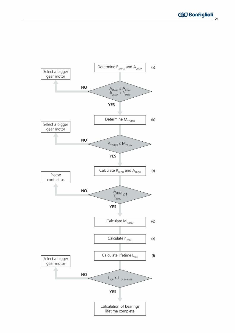
Service life of bearings
(a)Maximum radial force applied on output shaft R
2 MAX[N]
Please consider the specific conditions (e.g. belt drives under acceleration torque)
Maximum axial force applied on output shaft A2 MAX
[N]
(b) Maximum tilting moment applied on output shaftM
T 2
MAX
[Nm] MT 2 MAX = A2 MAX yR2 MAX ±(x + LZ)
1000
(c) Equivalent forces applied on output shaft
R2 EQU
[N] 3R2 EQU+ +
tnn2(n)...t1n2(1) ++
3 ...R2(1)t1n2(1)3R2(n)tnn2(n)
=
A2 EQU
[N] 3A2 EQU tnn2(n)...t1n2(1) +++ +3 ...A2(1)t1n2(1)
3A2(n)tnn2(n)=
(d) Equivalent tilting moment applied on output shaftM
T 2
EQU
[Nm] MT 2 EQU = A2 EQU yR2 EQU +(x + LZ)
1000
(e) Equivalent output speed n2 EQU
[min-1] n2 EQUtn...t2t1 +++
...t2n2(2)t1n2(1) n2(n) tn+++=
(f) Bearings basic rating life L10h
[h] =16666
L10h n2 EQU
CB p
MT 2 EQU
BMS 060 BMS 070 BMS 090 BMS 130 BMS 160
LZ
[mm] 48 72 78 100 128
MT 2 max
[Nm] 115 318 430 1200 3700
CB
[Nm] 490 1335 1815 5055 16200
p - 3.33 3.33 3.33 3.33 3.33
f 0.37
y
R2
x
R2
x
A2
y
A2
21
YES
Determine R2MAX
and A2MAX
NO
NO
YES
YES
NO
YES
NO
(a)
(b)
(c)
(d)
(e)
(f)
A2MAX
≤ A2max
R2MAX
≤ R2max
AT2MAX
≤ MT2max
Determine MT2MAX
Calculate R2EQU
and A2EQU
R2EQU
A2EQU ≤ f
Calculate MT2EQU
Calculate lifetime L10h
Calculation of bearingslifetime complete
Select a biggergear motor
Select a biggergear motor
Select a biggergear motor
Pleasecontact us
Calculate n2EQU
L10h
> L10h TARGET

22
Bonfiglioli Motion Solution (BMS) represents the edge of products integration. BMS is the result of the deep
knowledge Bonfiglioli has in precision planetary gearboxes and low inertia permanent magnet servomotor
technologies.
Compared to solutions based on separate units, interfaced BMS ensures several competitive advantages, such as:
• reduced outline dimensions
• maximized performances thanks to optimized gear motor selection
• longer lifetime
• higher stiffness
• top in class energy efficiency
Low-backlash planetary gearboxes of the BMS series feature a flanged output shaft and are perfectly suited for
high demanding applications in term of stiffness and radial load.
In combination with top class torque density and dynamics servomotors, BMS perfectly matches the performance
demand of every motion control application.
BMS series provides a straightforward selection of the compact unit using a unique selection method.
When dynamics and high precision are required, and compactness makes the difference, it is a relevant advantage
to have a mechatronic product easy to select, order and install.
BMSBonfiglioli Motion Solution

23
• Output torque: 8... 800 Nm
• Output speed: 43... 875 rpm
• Designed for continuous duty & intermittent duty
• Universal mounting position
• Power supply: 230 & 400 VAC
• Two classes of precision:
- 1-stage unit backlash: standard ϕS ≤ 5’- reduced ϕ
R ≤ 3’
- 2-stage unit backlash: standard ϕS ≤ 7’- reduced ϕ
R ≤ 5’
• IP65 degree of protection
• Ambient temperature -20 °C… +30 °C
• Lubrication optimized for S1 and S5 duty types
Distribution of nominal torque Mn2 [Nm]
[i] 4 5 7 10 16 20 25 28 35 40 50 70
BMS 060 30 30 25 20 30 30 30 30 30 - - -
BMS 070 70 70 60 40 70 70 70 70 70 70 70 60
BMS 090 200 180 160 110 200 180 180 200 180 200 180 -
BMS 130 400 400 360 280 400 400 400 400 400 400 400 360
BMS 160 - - - - 800 800 800 800 800 800 800 -
BMS features
Maximum Acceleration Torque
0 200 400 600 800 1000 1200
160 1200
090 300
130 600
070 100
060 45
Torque [Nm]
Gea
r M
oto
r si
ze
Duty BMS 060... BMS 160
S1 (continuous) Synthetic oil viscosity ISO VG 220
S5 (intermittent) NLGI grease consistency 00
Maximum Axial and Radial Load
Load [N]
Gea
r M
oto
r si
ze
0 5000 10000 15000 20000 25000 30000
160
090
130
070
060
4400
4300
5500
6800
12000
8500
29000
16000
2400
4300A
2 MAX
R2 MAX

24
BMS gear motor rating is defined by the torque-speed selected with the overspeed variant. The permissible operating range corresponds to the area in the torque-speed characteristics limited by the thermal, electrical and mechanical limit curves. The continuous operating zone is enclosed by torque curve for S1 duty up to the intersection with the voltage limit or the mechanical limit curve. Continuous duty above the S1 characteristic curve is not thermally permitted for the gear motor.The intermittent duty zone is the area between the short-term peak torque curve and the voltage limit or the mechanical limit curve.According to the application requirements, in terms of speed-torque and operation cycle, it is possible to select the suitable gear motor choosing between the BASE (B), MEDIUM (M) or HIGH (H) overspeed variants.
The following diagrams highlight the extension of the gear motor operating areas according to the selected overspeed (B, M, H). Applications that need high torque overloads at high speed require a MEDIUM or HIGH overspeed variant. On the other side, the selected overspeed affects the drive selection: the higher the maximum speed n
a2 the higher the required current I
a.
BMS overspeed
BMS
BASE OVERSPEED MEDIUM OVERSPEED HIGH OVERSPEED
Torq
ue [N
m]
Ma2
M02
Mn2
Continuous Duty
Intermittent Duty
Speed [min-1] nn2
na2
Torq
ue [N
m]
Ma2
M02
Mn2
Speed [min-1] nn2
na2
Continuous Duty
Intermittent Duty
Speed [min-1] nn2
na2
Continuous Duty
Intermittent Duty
Torq
ue [N
m]
Ma2
M02
Mn2
Torq
ue [N
m]
Torq
ue [N
m]
Ma2
M02
Mn2
Speed [min-1] Speed [min-1]na2
BASEOVERSPEED
MEDIUMOVERSPEED
HIGHOVERSPEED
na2
na2
Voltage limitMedium Overspeed
Voltage limitBase Overspeed
Peak limit
Mechanical limitHigh Overspeed
Continous duty limit Base Overspeed
Continous duty limitMedium & High Overspeed
Continuous Duty
Intermittent Duty
Intermittent Duty
HIGH OVERSPEED + +
MEDIUM OVERSPEED +
BASE OVERSPEED +
Continuous Duty
HIGH OVERSPEED +
MEDIUM OVERSPEED +
BASE OVERSPEED +

25
BMS designation
Gear motor seriesBMS
VersionF Flanged
Gearbox size060... 160
OverspeedB BaseM MediumH High
Gear ratio4... 70
Motor size065A... 170C
Supply AC voltage230 230 V400 400 V
BMS 5060 400F 065BB S1 F24PTCUH1 ANRES1STD
Thermal protectionPTC PTCKTY KTY84-130TC1 PT1000
DutyS1 Continuous dutyS5 Intermittent duty
Lubricant(blank) Standard (default)UH1 Food grade synthetic lubricant
Brake(blank) No brake or flywheel (default)F24 Brake 24 VdcF1 Additional flywheel / inertia
ConnectionsAN Angled turning receptaclesST Straight receptacles
Feedback deviceRES1(1) 2-pole resolver 8 kHzRES2 2-pole resolver 10 kHzENB1 Optical encoder EnDat Single TurnENB2 Optical encoder EnDat Multi TurnENB3 Optical encoder Hiperface Single TurnENB4 Optical encoder Hiperface Multi TurnENB5 Capacitive encoder Hiperface Single TurnENB6 Capacitive encoder Hiperface Multi Turn
Backlash
Gear ratio ≤10 Gear ratio >10
STD ϕs ≤ 5’ ϕ
s ≤ 7’
LOW ϕR ≤ 3’ ϕ
R ≤ 5’
(1) Not available for motor sizes 065A and 065B
26
VLLp
LLs
ø 4.5 x8M5 x8
LB
8
4
7
14
4
19.5
AF
AD
pA
C
AC
AD
s
ø 20
H7
x4
ø 40
h7
ø 64
h7
ø 50
R 0.5ø 31.5
ø 79
ø 86
45°
45°
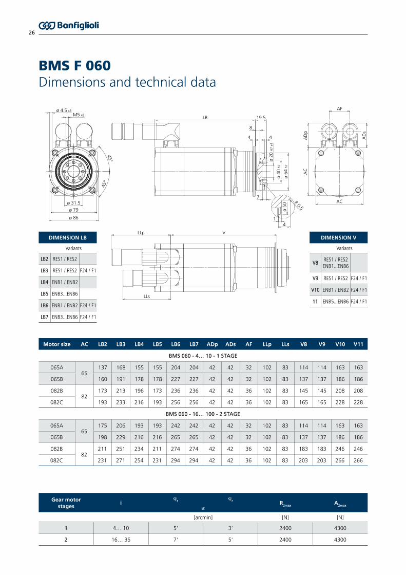
BMS F 060 Dimensions and technical data
Motor size AC LB2 LB3 LB4 LB5 LB6 LB7 ADp ADs AF LLp LLs V8 V9 V10 V11
BMS 060 - 4… 10 - 1 STAGE
065A65
137 168 155 155 204 204 42 42 32 102 83 114 114 163 163
065B 160 191 178 178 227 227 42 42 32 102 83 137 137 186 186
082B82
173 213 196 173 236 236 42 42 36 102 83 145 145 208 208
082C 193 233 216 193 256 256 42 42 36 102 83 165 165 228 228
BMS 060 - 16… 100 - 2 STAGE
065A65
175 206 193 193 242 242 42 42 32 102 83 114 114 163 163
065B 198 229 216 216 265 265 42 42 32 102 83 137 137 186 186
082B82
211 251 234 211 274 274 42 42 36 102 83 183 183 246 246
082C 231 271 254 231 294 294 42 42 36 102 83 203 203 266 266
Gear motorstages
iϕs ϕr R2max A2max≤
[arcmin] [N] [N]
1 4… 10 5' 3' 2400 4300
2 16… 35 7' 5' 2400 4300
DIMENSION LB
Variants
LB2 RES1 / RES2
LB3 RES1 / RES2 F24 / F1
LB4 ENB1 / ENB2
LB5 ENB3...ENB6
LB6 ENB1 / ENB2 F24 / F1
LB7 ENB3...ENB6 F24 / F1
DIMENSION V
Variants
V8RES1 / RES2ENB1...ENB6
V9 RES1 / RES2 F24 / F1
V10 ENB1 / ENB2 F24 / F1
11 ENB5...ENB6 F24 / F1

27
BMS F 060 Performance data • Base overspeed
Designation nn2 na2 Mn2 M02 Ma2 Mp2 In I0 Ia Ip Ct J1 m Kp
[min-1] [min-1] [Nm] [Nm] [Nm] [Nm] [A] [A] [A] [A] [Nm/arcmin] [kg cm2] [kg]
BMS F 060 B 35 065A400
86 106 28 30 45 800.72 0.76 1.23 2.18
12 0.28 3.9 7.4230 1.16 1.23 1.97 3.50
BMS F 060 B 28 065A400
107 125 22 24 45 710.72 0.76 1.53 2.43
12 0.28 3.9 8.3230 1.16 1.23 2.46 3.90
BMS F 060 B 25 065A400
120 124 20 21 45 640.72 0.76 1.72 2.43
12 0.31 3.9 8.8230 1.16 1.23 2.75 3.90
BMS F 060 B 20 065A400
150 130 16 17 45 510.72 0.76 2.14 2.43
12 0.33 3.9 10230 1.16 1.23 3.44 3.90
BMS F 060 B 16 065A400
188 156 13 14 41 410.72 0.76 2.43 2.43
12 0.34 3.9 11230 1.16 1.23 3.90 3.90
BMS F 060 B 16 065B400
188 194 26 27 45 781.33 1.35 2.64 4.60
12 0.54 4.5 20230 2.30 2.30 4.59 8.00
BMS F 060 B 10 065A400
300 250 8.0 9.0 26 260.72 0.76 2.43 2.43
12 0.27 2.9 17230 1.16 1.23 3.90 3.90
BMS F 060 B 10 065B400
300 300 16 17 30 491.33 1.35 2.82 4.60
12 0.47 3.5 32230 2.30 2.30 4.90 8.00
BMS F 060 B 7 065B400
429 286 11 12 34 341.33 1.35 4.56 4.56
12 0.49 3.5 46230 2.30 2.30 7.93 7.93
BMS F 060 B 7 082B400
429 443 21 22 38 592.50 2.60 5.68 8.83
12 1.49 5.1 28230 4.30 4.50 9.90 15.4
BMS F 060 B 5 065B400
600 400 8.0 9.0 25 251.33 1.35 4.60 4.60
13 0.53 3.5 65230 2.30 2.30 8.00 8.00
BMS F 060 B 5 082B400
600 440 15 16 43 432.50 2.60 8.90 8.90
13 1.53 5.1 39230 4.3 4.5 15.5 15.5
BMS F 060 B 5 082C400
600 560 19 22 45 582.90 3.30 7.75 9.90
13 1.83 6.2 49230 5.10 5.80 13.6 17.4
BMS F 060 B 4 082B400
750 550 12 13 34 342.50 2.60 8.90 8.90
13 1.58 5.1 47230 4.30 4.50 15.5 15.5
BMS F 060 B 4 082C400
750 575 15 18 45 462.90 3.30 9.68 9.90
13 1.88 6.2 59230 5.10 5.80 17.0 17.4

28
BMS F 060 Performance data • Medium overspeed
Designation nn2 na2 Mn2 M02 Ma2 Mp2 In I0 Ia Ip Ct J1 m Kp
[min-1] [min-1] [Nm] [Nm] [Nm] [Nm] [A] [A] [A] [A] [Nm/arcmin] [kg cm2] [kg]
BMS F 060 M 35 065A400
129 142 27 30 45 800.88 0.98 1.56 2.78
12 0.28 3.9 7.4230 1.74 1.90 3.13 5.56
BMS F 060 M 28 065A400
161 161 21 24 45 710.88 0.98 1.95 3.10
12 0.28 3.9 8.3230 1.74 1.90 3.91 6.20
BMS F 060 M 25 065A400
180 164 19 21 45 640.88 0.98 2.19 3.10
12 0.31 3.9 8.8230 1.74 1.90 4.38 6.20
BMS F 060 M 20 065A400
225 175 15 17 45 510.88 0.98 2.74 3.10
12 0.33 3.9 10230 1.74 1.90 5.47 6.20
BMS F 060 M 16 065A400
281 188 12 14 41 410.88 0.98 3.10 3.10
12 0.34 3.9 11230 1.74 1.90 6.20 6.20
BMS F 060 M 16 065B400
281 312 24 27 45 781.85 1.98 3.85 6.70
12 0.54 4.5 20230 3.20 3.40 6.60 11.5
BMS F 060 M 10 065A400
400 300 7.6 9.0 26 260.88 0.98 3.10 3.10
12 0.27 2.9 17230 1.74 1.90 6.20 6.20
BMS F 060 M 10 065B400
400 500 15 17 30 491.85 1.98 4.10 6.70
12 0.47 3.5 32230 3.20 3.40 7.04 11.5
BMS F 060 M 7 065B400
571 500 11 12 34 341.85 1.98 6.64 6.64
12 0.49 3.5 46230 3.20 3.40 11.4 11.4
BMS F 060 M 7 082B400
571 714 20 22 38 593.40 3.90 8.43 13.1
12 1.49 5.1 28230 5.30 6.00 13.2 20.4
BMS F 060 M 5 065B400
700 700 7.6 9.0 25 251.85 1.98 6.70 6.70
13 0.53 3.5 65230 3.20 3.40 11.5 11.5
BMS F 060 M 5 082B400
700 700 14 16 43 433.40 3.90 13.2 13.2
13 1.53 5.1 39230 5.30 6.00 20.6 20.6
BMS F 060 M 5 082C400
700 800 18 22 45 583.90 4.80 11.3 14.4
13 1.83 6.2 49230 6.80 8.40 19.6 25.1
BMS F 060 M 4 082B400
875 875 11 13 34 343.40 3.90 13.2 13.2
13 1.58 5.1 47230 5.30 6.00 20.6 20.6
BMS F 060 M 4 082C400
875 875 14 18 45 463.90 4.80 14.1 14.4
13 1.88 6.2 59230 6.80 8.40 24.6 25.1

29
BMS F 060 Performance data • High overspeed
Designation nn2 na2 Mn2 M02 Ma2 Mp2 In I0 Ia Ip Ct J1 m Kp
[min-1] [min-1] [Nm] [Nm] [Nm] [Nm] [A] [A] [A] [A] [Nm/arcmin] [kg cm2] [kg]
BMS F 060 H 35 065A400
129 171 27 30 45 801.21 1.38 2.22 3.94
12 0.28 3.9 7.4230 2.09 2.39 3.88 6.90
BMS F 060 H 28 065A400
161 214 21 24 45 711.21 1.38 2.77 4.40
12 0.28 3.9 8.3230 2.09 2.39 4.85 7.70
BMS F 060 H 25 065A400
180 240 19 21 45 641.21 1.38 3.11 4.40
12 0.31 3.9 8.8230 2.09 2.39 5.44 7.70
BMS F 060 H 20 065A400
225 250 15 17 45 511.21 1.38 3.88 4.40
12 0.33 3.9 10230 2.09 2.39 6.79 7.70
BMS F 060 H 16 065A400
281 281 12 14 41 411.21 1.38 4.40 4.40
12 0.34 3.9 11230 2.09 2.39 7.70 7.70
BMS F 060 H 16 065B400
281 375 24 27 45 782.43 2.68 5.22 9.10
12 0.54 4.5 20230 4.20 4.70 9.13 15.9
BMS F 060 H 10 065A400
400 450 7.6 9.0 26 261.21 1.38 4.40 4.40
12 0.27 2.9 17230 2.09 2.39 7.70 7.70
BMS F 060 H 10 065B400
400 600 15 17 30 492.43 2.68 5.57 9.10
12 0.47 3.5 32230 4.20 4.70 9.73 15.9
BMS F 060 H 7 065B400
571 714 11 12 34 342.43 2.68 9.02 9.02
12 0.49 3.5 46230 4.20 4.70 15.8 15.8
BMS F 060 H 7 082B400
571 857 20 22 38 594.30 5.20 11.3 17.6
12 1.49 5.1 28230 7.60 9.00 19.8 30.7
BMS F 060 H 5 065B400
700 1000 7.6 9.0 25 252.43 2.68 9.10 9.10
13 0.53 3.5 65230 4.20 4.70 15.9 15.9
BMS F 060 H 5 082B400
700 1000 14 16 43 434.30 5.20 17.7 17.7
13 1.53 5.1 39230 7.60 9.00 31.0 31.0
BMS F 060 H 5 082C400
700 1100 18 22 45 584.50 6.20 14.6 18.6
13 1.83 6.2 49230 7.60 10.6 25.0 32.0
BMS F 060 H 4 082B400
875 1250 11 13 34 344.30 5.20 17.7 17.7
13 1.58 5.1 47230 7.60 9.00 31.0 31.0
BMS F 060 H 4 082C400
875 1175 14 18 45 464.50 6.20 18.2 18.6
13 1.88 6.2 59230 7.60 10.6 31.3 32.0
30
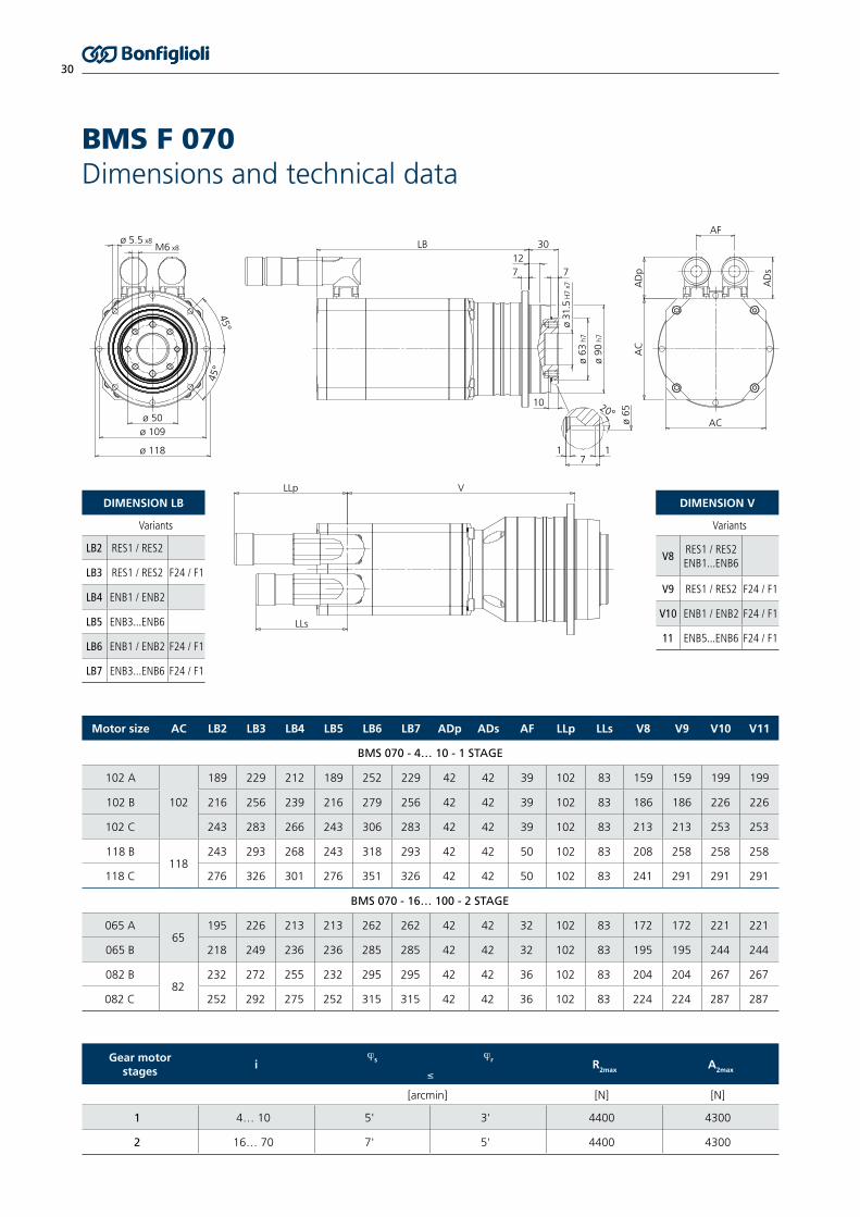
BMS F 070 Dimensions and technical data
Gear motorstages
iϕs ϕr R2max A2max≤
[arcmin] [N] [N]
1 4… 10 5' 3' 4400 4300
2 16… 70 7' 5' 4400 4300
Motor size AC LB2 LB3 LB4 LB5 LB6 LB7 ADp ADs AF LLp LLs V8 V9 V10 V11
BMS 070 - 4… 10 - 1 STAGE
102 A
102
189 229 212 189 252 229 42 42 39 102 83 159 159 199 199
102 B 216 256 239 216 279 256 42 42 39 102 83 186 186 226 226
102 C 243 283 266 243 306 283 42 42 39 102 83 213 213 253 253
118 B118
243 293 268 243 318 293 42 42 50 102 83 208 258 258 258
118 C 276 326 301 276 351 326 42 42 50 102 83 241 291 291 291
BMS 070 - 16… 100 - 2 STAGE
065 A65
195 226 213 213 262 262 42 42 32 102 83 172 172 221 221
065 B 218 249 236 236 285 285 42 42 32 102 83 195 195 244 244
082 B 82
232 272 255 232 295 295 42 42 36 102 83 204 204 267 267
082 C 252 292 275 252 315 315 42 42 36 102 83 224 224 287 287
45°
45°
ø 5.5 x8
ø 50
LB
LLp V
LLs
30AF
AD
pA
C
AC
AD
s
ø 31
.5 H
7 x7
ø 63
h7
ø 90
h7
ø 65
20°
127
71 1
10
7
ø 109
ø 118
M6 x8
DIMENSION LB
Variants
LB2 RES1 / RES2
LB3 RES1 / RES2 F24 / F1
LB4 ENB1 / ENB2
LB5 ENB3...ENB6
LB6 ENB1 / ENB2 F24 / F1
LB7 ENB3...ENB6 F24 / F1
DIMENSION V
Variants
V8RES1 / RES2ENB1...ENB6
V9 RES1 / RES2 F24 / F1
V10 ENB1 / ENB2 F24 / F1
11 ENB5...ENB6 F24 / F1
31
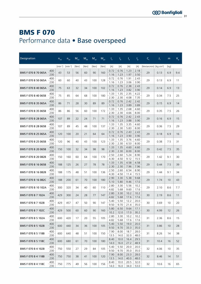
BMS F 070 Performance data • Base overspeed
Designation nn2 na2 Mn2 M02 Ma2 Mp2 In I0 Ia Ip Ct J1 m Kp
[min-1] [min-1] [Nm] [Nm] [Nm] [Nm] [A] [A] [A] [A] [Nm/arcmin] [kg cm2] [kg]
BMS F 070 B 70 065A400
43 53 56 60 90 1600.72 0.76 1.23 2.18
29 0.13 6.9 9.4230 1.16 1.23 1.97 3.50
BMS F 070 B 50 065A400
60 60 40 43 100 1280.72 0.76 1.91 2.43
29 0.13 6.9 11230 1.16 1.23 3.06 3.90
BMS F 070 B 40 065A400
75 63 32 34 100 1020.72 0.76 2.38 2.43
29 0.14 6.9 13230 1.16 1.23 3.82 3.90
BMS F 070 B 40 065B400
75 85 64 68 100 1801.33 1.35 2.35 4.22
29 0.34 7.5 25230 2.30 2.30 4.08 7.35
BMS F 070 B 35 065A400
86 71 28 30 89 890.72 0.76 2.42 2.42
29 0.15 6.9 14230 1.16 1.23 3.89 3.89
BMS F 070 B 35 065B400
86 86 56 60 100 1721.33 1.35 2.68 4.60
29 0.35 7.5 26230 2.30 2.30 4.66 8.00
BMS F 070 B 28 065A400
107 89 22 24 71 710.72 0.76 2.42 2.43
29 0.16 6.9 15230 1.16 1.23 3.88 3.90
BMS F 070 B 28 065B400
107 89 45 48 100 1371.33 1.35 3.35 4.60
29 0.36 7.5 29230 2.30 2.30 5.83 8.00
BMS F 070 B 25 065A400
120 100 20 21 64 640.72 0.76 2.43 2.43
29 0.18 6.9 16230 1.16 1.23 3.90 3.90
BMS F 070 B 25 065B400
120 96 40 43 100 1231.33 1.35 3.76 4.60
29 0.38 7.5 31230 2.30 2.30 6.53 8.00
BMS F 070 B 20 065B400
150 100 32 34 98 981.33 1.35 4.60 4.60
29 0.42 7.5 35230 2.30 2.30 8.00 8.00
BMS F 070 B 20 082B400
150 160 60 64 100 1702.50 2.60 5.24 8.90
29 1.42 9.1 30230 4.30 4.50 9.12 15.5
BMS F 070 B 16 065B400
188 125 26 27 78 781.33 1.35 4.58 4.58
29 0.44 7.5 39230 2.30 2.30 7.96 7.96
BMS F 070 B 16 082B400
188 175 48 51 100 1362.50 2.60 6.54 8.90
29 1.44 9.1 34230 4.30 4.50 11.4 15.5
BMS F 070 B 16 082C400
188 200 61 70 100 1802.90 3.30 5.38 9.68
29 1.74 10 43230 5.10 5.80 9.46 17.0
BMS F 070 B 10 102A400
300 320 34 40 60 1102.80 3.30 5.56 10.2
29 2.10 8.6 7.7230 4.82 5.68 9.60 17.6
BMS F 070 B 7 102A400
429 300 24 28 77 1472.80 3.30 10.2 10.2
30 2.19 8.6 11230 4.82 5.68 17.6 17.6
BMS F 070 B 7 102B400
429 457 47 50 90 1475.40 5.50 12.2 20.0
30 3.69 10 20230 9.50 9.70 21.4 35.0
BMS F 070 B 7 102C400
429 500 60 60 90 1605.80 6.50 9.64 17.1
30 4.99 12 26230 10.2 12.0 17.0 30.2
BMS F 070 B 5 102A400
600 420 17 20 55 1052.80 3.30 10.2 10.2
31 2.36 8.6 15230 4.82 5.68 17.6 17.6
BMS F 070 B 5 102B400
600 440 34 36 100 1055.40 5.50 19.0 20.0
31 3.86 10 28230 9.50 9.70 33.3 35.0
BMS F 070 B 5 118B400
600 640 48 51 100 1507.90 8.00 18.7 28.0
31 8.26 14 38230 13.5 14.0 32.0 48.0
BMS F 070 B 5 118C400
600 680 61 70 100 1808.40 10.0 16.4 29.5
31 10.4 16 52230 14.0 16.0 27.2 48.9
BMS F 070 B 4 102B400
750 550 27 29 84 1055.40 5.50 20.0 20.0
32 4.06 10 35230 9.50 9.70 35.0 35.0
BMS F 070 B 4 118B400
750 750 38 41 100 1207.90 8.00 23.3 28.0
32 8.46 14 51230 13.5 14.0 40.0 48.0
BMS F 070 B 4 118C400
750 775 49 56 100 1568.40 10.0 20.5 32.0
32 10.6 16 65230 14.0 16.0 34.0 53.0

32
BMS F 070 Performance data • Medium overspeed
Designation nn2 na2 Mn2 M02 Ma2 Mp2 In I0 Ia Ip Ct J1 m Kp
[min-1] [min-1] [Nm] [Nm] [Nm] [Nm] [A] [A] [A] [A] [Nm/arcmin] [kg cm2] [kg]
BMS F 070 M 70 065A400
57 71 55 60 90 1600.88 0.98 1.56 2.78
29 0.13 6.9 9.4230 1.74 1.90 3.13 5.56
BMS F 070 M 50 065A400
70 80 39 43 100 1280.88 0.98 2.43 3.10
29 0.13 6.9 11230 1.74 1.90 4.86 6.20
BMS F 070 M 40 065A400
88 75 31 34 100 1020.88 0.98 3.04 3.10
29 0.14 6.9 13230 1.74 1.90 6.08 6.20
BMS F 070 M 40 065B400
88 130 62 68 100 1801.85 1.98 3.42 6.15
29 0.34 7.5 25230 3.20 3.40 5.87 10.6
BMS F 070 M 35 065A400
100 86 27 30 89 890.88 0.98 3.09 3.09
29 0.15 6.9 14230 1.74 1.90 6.18 6.18
BMS F 070 M 35 065B400
100 143 55 60 100 1721.85 1.98 3.91 6.70
29 0.35 7.5 26230 3.20 3.40 6.71 11.5
BMS F 070 M 28 065A400
125 107 22 24 71 710.88 0.98 3.08 3.10
29 0.16 6.9 15230 1.74 1.90 6.17 6.20
BMS F 070 M 28 065B400
125 161 44 48 100 1371.85 1.98 4.88 6.70
29 0.36 7.5 29230 3.20 3.40 8.38 11.5
BMS F 070 M 25 065A400
140 120 20 21 64 640.88 0.98 3.10 3.10
29 0.18 6.9 16230 1.74 1.90 6.20 6.20
BMS F 070 M 25 065B400
140 160 39 43 100 1231.85 1.98 5.47 6.70
29 0.38 7.5 31230 3.20 3.40 9.39 11.5
BMS F 070 M 20 065B400
175 175 31 34 98 981.85 1.98 6.70 6.70
29 0.42 7.5 35230 3.20 3.40 11.5 11.5
BMS F 070 M 20 082B400
175 250 58 64 100 1703.40 3.90 7.76 13.2
29 1.42 9.1 30230 5.30 6.00 12.1 20.6
BMS F 070 M 16 065B400
219 219 25 27 78 781.85 1.98 6.67 6.67
29 0.44 7.5 39230 3.20 3.40 11.4 11.4
BMS F 070 M 16 082B400
219 281 46 51 100 1363.40 3.90 9.71 13.2
29 1.44 9.1 34230 5.30 6.00 15.1 20.6
BMS F 070 M 16 082C400
219 313 59 70 100 1803.90 4.80 7.83 14.1
29 1.74 10 43230 6.80 8.40 13.6 24.6
BMS F 070 M 10 102A400
350 510 33 40 60 1103.80 4.90 8.18 15.0
29 2.10 8.6 7.7230 6.88 8.82 14.9 27.3
BMS F 070 M 7 102A400
500 500 23 28 77 1473.80 4.90 15.0 15.0
30 2.19 8.6 11230 6.88 8.82 27.3 27.3
BMS F 070 M 7 102B400
500 714 45 50 90 1477.50 8.30 18.4 30.0
30 3.69 10 20230 12.6 14.0 31.2 51.0
BMS F 070 M 7 102C400
500 714 57 60 90 1607.80 9.70 14.2 25.3
30 4.99 12 26230 13.5 17.0 24.8 44.1
BMS F 070 M 5 102A400
600 700 17 20 55 1053.80 4.90 15.0 15.0
31 2.36 8.6 15230 6.88 8.82 27.3 27.3
BMS F 070 M 5 102B400
600 800 32 36 100 1057.50 8.30 28.6 30.0
31 3.86 10 28230 12.6 14.0 48.6 51.0
BMS F 070 M 5 118B400
600 1000 46 51 100 15010.2 12.0 26.7 40.0
31 8.26 14 38230 18.3 21.0 48.7 73.0
BMS F 070 M 5 118C400
600 1000 58 70 100 18010.9 14.0 24.1 43.4
31 10.4 16 52- - - - -
BMS F 070 M 4 102B400
750 760 26 29 84 1057.50 8.30 30.0 30.0
32 4.06 10 35230 12.6 14.0 51.0 51.0
BMS F 070 M 4 118B400
750 1125 36 41 100 12010.2 12.0 33.3 40.0
32 8.46 14 51230 18.3 21.0 60.8 73.0
BMS F 070 M 4 118C400
750 1125 46 56 100 15610.9 14.0 30.1 47.0
32 10.6 16 65- - - - -

33
BMS F 070 Performance data • High overspeed
Designation nn2 na2 Mn2 M02 Ma2 Mp2 In I0 Ia Ip Ct J1 m Kp
[min-1] [min-1] [Nm] [Nm] [Nm] [Nm] [A] [A] [A] [A] [Nm/arcmin] [kg cm2] [kg]
BMS F 070 H 70 065A400
57 86 55 60 90 1601.21 1.38 2.22 3.94
29 0.13 6.9 9.4230 2.09 2.39 3.88 6.90
BMS F 070 H 50 065A400
70 110 39 43 100 1281.21 1.38 3.45 4.40
29 0.13 6.9 11230 2.09 2.39 6.04 7.70
BMS F 070 H 40 065A400
88 105 31 34 100 1021.21 1.38 4.31 4.40
29 0.14 6.9 13230 2.09 2.39 7.55 7.70
BMS F 070 H 40 065B400
88 150 62 68 100 1802.43 2.68 4.64 8.36
29 0.34 7.5 25230 4.20 4.70 8.11 14.6
BMS F 070 H 35 065A400
100 120 27 30 89 891.21 1.38 4.39 4.39
29 0.15 6.9 14230 2.09 2.39 7.68 7.68
BMS F 070 H 35 065B400
100 171 55 60 100 1722.43 2.68 5.31 9.10
29 0.35 7.5 26230 4.20 4.70 9.27 15.9
BMS F 070 H 28 065A400
125 150 22 24 71 711.21 1.38 4.38 4.40
29 0.16 6.9 15230 2.09 2.39 7.66 7.70
BMS F 070 H 28 065B400
125 214 44 48 100 1372.43 2.7 6.63 9.10
29 0.36 7.5 29230 4.20 4.70 11.6 15.9
BMS F 070 H 25 065A400
140 168 20 21 64 641.21 1.38 4.40 4.40
29 0.18 6.9 16230 2.09 2.39 7.70 7.70
BMS F 070 H 25 065B400
140 232 39 43 100 1232.43 2.68 7.43 9.10
29 0.38 7.5 31230 4.20 4.70 13.0 15.9
BMS F 070 H 20 065B400
175 250 31 34 98 982.43 2.68 9.10 9.10
29 0.42 7.5 35230 4.20 4.70 15.9 15.9
BMS F 070 H 20 082B400
175 300 58 64 100 1704.30 5.20 10.4 17.7
29 1.42 9.1 30230 7.60 9.00 18.2 31.0
BMS F 070 H 16 065B400
219 313 25 27 78 782.43 2.68 9.05 9.05
29 0.44 7.5 39230 4.20 4.70 15.8 15.8
BMS F 070 H 16 082B400
219 375 46 51 100 1364.30 5.20 13.0 17.7
29 1.44 9.1 34230 7.60 9.00 22.8 31.0
BMS F 070 H 16 082C400
219 375 59 70 100 1804.50 6.20 10.1 18.2
29 1.74 10 43230 7.60 10.6 17.4 31.3
BMS F 070 H 10 102A400
350 600 33 40 60 1104.60 6.30 10.4 19.0
29 2.10 8.6 7.7230 8.29 11.4 19.1 35.1
BMS F 070 H 7 102A400
500 643 23 28 77 1474.60 6.30 19.0 19.0
30 2.19 8.6 11230 8.29 11.4 35.1 35.1
BMS F 070 H 7 102B400
500 857 45 50 90 1479.30 11.0 24.5 40.0
30 3.69 10 20230 15.40 18.2 40.4 66.0
BMS F 070 H 7 102C400
500 857 57 60 90 1608.40 12.4 18.4 32.7
30 4.99 12 26230 14.80 21.8 32.1 57.1
BMS F 070 H 5 102A400
600 900 17 20 55 1054.60 6.30 19.0 19.0
31 2.36 8.6 15230 8.29 11.4 35.1 35.1
BMS F 070 H 5 102B400
600 1080 32 36 100 1059.30 11.0 38.1 40.0
31 3.86 10 28230 15.40 18.2 62.9 66.0
BMS F 070 H 5 118B400
600 1200 46 51 100 15011.40 15.8 36.7 55.0
31 8.26 14 38- - - - -
BMS F 070 H 5 118C400
600 1200 58 70 100 18011.80 18.9 31.8 57.2
31 10.4 16 52- - - - -
BMS F 070 H 4 102B400
750 135 26 29 84 1059.30 11.0 40.0 40.0
32 4.06 10 35230 15.40 18.2 66.0 66.0
BMS F 070 H 4 118B400
750 1500 36 41 100 12011.40 15.8 45.8 55.0
32 8.46 14 51- - - - -
BMS F 070 H 4 118C400
750 1500 46 56 100 15611.80 18.9 39.7 62.0
32 10.6 16 65- - - - -

34
BMS F 090 Dimensions and technical data
Gear motorstages
iϕs ϕr R2max A2max≤
[arcmin] [N] [N]
1 4… 10 5' 3' 5500 6800
2 16… 50 7' 5' 5500 6800
Motor size AC LB2 LB3 LB4 LB5 LB6 LB7 ADp ADs AF LLp LLs V8 V9 V10 V11
BMS 090 - 4… 10 - 1 STAGE
118 A
118
218 268 243 218 293 268 42 42 50 102 83 183 233 233 233
118 B 249 299 274 249 324 299 42 42 50 102 83 214 264 264 264
118 C 282 332 307 282 357 332 42 42 50 102 83 247 297 297 297
145 B145
268 318 293 268 343 318 42 42 45 102 83 233 283 283 283
145 C 303 353 328 303 378 353 42 42 45 102 83 268 318 318 318
170 B170
294 369 332 294 407 369 62 42 90 129 83 267 342 342 342
170 C 348 423 386 348 461 423 62 42 90 129 83 321 396 396 396
BMS 090 - 16… 100 - 2 STAGE
102 A
102
237 277 260 237 300 277 42 42 39 102 83 207 207 247 247
102 B 264 304 287 264 327 304 42 42 39 102 83 234 234 274 274
102 C 291 331 314 291 354 331 42 42 39 102 83 261 261 301 301
118 B118
292 342 317 292 367 342 42 42 50 102 83 325 325 365 365
118 C 325 375 350 325 400 375 42 42 50 102 83 352 352 392 392
ø 5.5 x8
LB 29AF
AD
pA
C
AC
AD
s
ø 40
H7
x6
ø 11
0 h7
ø 80
h7
11
12
1
20°
7
8 7
ø 63ø 135ø 145
M6 x12
22.5°22.5°
45°
LLp V
LLs
DIMENSION LB
Variants
LB2 RES1 / RES2
LB3 RES1 / RES2 F24 / F1
LB4 ENB1 / ENB2
LB5 ENB3...ENB6
LB6 ENB1 / ENB2 F24 / F1
LB7 ENB3...ENB6 F24 / F1
DIMENSION V
Variants
V8RES1 / RES2ENB1...ENB6
V9 RES1 / RES2 F24 / F1
V10 ENB1 / ENB2 F24 / F1
11 ENB5...ENB6 F24 / F1

35
BMS F 090 Performance data • Base overspeed
Designation nn2 na2 Mn2 M02 Ma2 Mp2 In I0 Ia Ip Ct J1 m Kp
[min-1] [min-1] [Nm] [Nm] [Nm] [Nm] [A] [A] [A] [A] [Nm/arcmin] [kg cm2] [kg]
BMS F 090 B 50 102A400
60 70 170 200 280 5002.80 3.30 5.19 9.27
70 1.72 14 10230 4.82 5.68 8.96 16.0
BMS F 090 B 40 102A400
75 75 136 160 300 5002.80 3.30 6.95 10.2
70 1.73 14 11230 4.82 5.68 12.0 17.6
BMS F 090 B 35 102A400
86 80 119 140 280 5002.80 3.30 7.42 10.2
70 1.77 14 13230 4.82 5.68 12.8 17.6
BMS F 090 B 28 102A400
107 79 95 112 300 5002.80 3.30 9.94 10.2
70 1.78 14 15230 4.82 5.68 17.1 17.6
BMS F 090 B 28 102B400
107 125 188 200 300 5005.40 5.50 10.2 17.0
70 3.28 15 26230 9.50 9.70 17.9 29.8
BMS F 090 B 25 102A400
120 88 85 100 275 5002.80 3.30 10.2 10.2
70 1.86 14 15230 4.82 5.68 17.6 17.6
BMS F 090 B 25 102B400
120 140 168 180 280 5005.40 5.50 10.7 19.0
70 3.36 15 28230 9.50 9.70 18.7 33.3
BMS F 090 B 20 102B400
150 150 134 144 280 4205.40 5.50 13.3 20.0
70 3.46 15 31230 9.50 9.70 23.3 35.0
BMS F 090 B 20 102C400
150 160 170 180 280 5005.80 6.50 10.5 18.8
70 4.76 17 37230 10.2 12.0 18.5 33.0
BMS F 090 B 16 102B400
188 156 107 115 300 3365.40 5.50 17.9 20.0
70 3.49 15 41230 9.50 9.70 31.3 35.0
BMS F 090 B 16 118B400
188 219 152 163 300 4807.90 8.00 17.5 28.0
70 7.89 19 19230 13.5 14.0 30.0 48.0
BMS F 090 B 16 118C400
188 219 195 200 300 5008.40 10.0 15.4 25.6
70 10.0 21 26230 14.0 16.0 25.5 42.5
BMS F 090 B 10 118A400
300 250 51 56 150 1503.90 4.30 14.0 14.0
70 4.78 15 13230 6.64 7.30 23.9 23.9
BMS F 090 B 10 118B400
300 360 95 102 170 3007.90 8.00 15.9 28.0
70 8.18 17 26230 13.5 14.0 27.2 48.0
BMS F 090 B 7 118B400
429 386 67 71 210 2107.90 8.00 28.0 28.0
72 8.35 17 37230 13.5 14.0 48.0 48.0
BMS F 090 B 7 118C400
429 357 85 98 250 2738.40 10.0 29.3 32.0
72 10.5 19 46230 14.0 16.0 48.5 53.0
BMS F 090 B 7 145B400
429 400 112 118 250 32212.5 13.0 38.8 50.0
72 13.4 22 50230 21.9 23.0 68.3 88.0
BMS F 090 B 7 145C400
429 429 134 154 250 41314.2 16.0 32.7 54.0
72 18.2 25 58230 22.9 27.0 52.7 87.0
BMS F 090 B 5 118B400
500 540 48 51 150 1507.90 8.00 28.0 28.0
75 8.67 17 51230 13.5 14.0 48.0 48.0
BMS F 090 B 5 118C400
500 480 61 70 195 1958.40 10.0 32.0 32.0
75 10.8 19 65230 14.0 16.0 53.0 53.0
BMS F 090 B 5 145B400
500 480 80 84 230 23012.5 13.0 50.0 50.0
75 13.7 22 67230 21.9 23.0 88.0 88.0
BMS F 090 B 5 145C400
500 400 96 110 280 29514.2 16.0 51.3 54.0
75 18.5 25 81230 22.9 27.0 82.6 87.0
BMS F 090 B 5 170B400
500 640 138 170 280 45018.6 23.0 43.6 70.0
75 29.1 32 89230 32.2 40.0 75.3 121
BMS F 090 B 5 170C400
500 640 180 180 280 50024.9 31.0 43.0 76.8
75 48.4 37 116- - - - -
BMS F 090 B 4 145B400
625 600 64 67 184 18412.5 13.0 50.0 50.0
77 14.0 22 85230 21.9 23.0 88.0 88.0
BMS F 090 B 4 145C400
625 500 77 88 236 23614.2 16.0 54.0 54.0
77 18.8 25 101230 22.9 27.0 87.0 87.0
BMS F 090 B 4 170B400
625 625 110 136 300 36018.6 23.0 58.3 70.0
77 29.4 32 99230 32.2 40.0 101 121
BMS F 090 B 4 170C400
625 750 144 180 300 50024.9 31.0 57.6 96.0
77 48.7 37 127- - - - -

36
BMS F 090 Performance data • Medium overspeed
Designation nn2 na2 Mn2 M02 Ma2 Mp2 In I0 Ia Ip Ct J1 m Kp
[min-1] [min-1] [Nm] [Nm] [Nm] [Nm] [A] [A] [A] [A] [Nm/arcmin] [kg cm2] [kg]
BMS F 090 M 50 102A400
70 90 165 200 280 5003.80 4.90 7.64 13.6
70 1.72 14 10230 6.88 8.82 13.9 24.8
BMS F 090 M 40 102A400
75 113 136 160 300 5003.80 4.90 10.2 15.0
70 1.73 14 11230 6.88 8.82 18.6 27.3
BMS F 090 M 35 102A400
86 129 119 140 280 5003.80 4.90 10.9 15.0
70 1.77 14 13230 6.88 8.82 19.9 27.3
BMS F 090 M 28 102A400
107 125 95 112 300 5003.80 4.90 14.6 15.0
70 1.78 14 15230 6.88 8.82 26.6 27.3
BMS F 090 M 28 102B400
107 161 188 200 300 5007.50 8.30 15.3 25.5
70 3.28 15 26230 12.6 14.0 26.0 43.4
BMS F 090 M 25 102A400
120 140 85 100 275 5003.80 4.90 15.0 15.0
70 1.86 14 15230 6.88 8.82 27.3 27.3
BMS F 090 M 25 102B400
120 180 168 180 280 5007.50 8.30 16.0 28.6
70 3.36 15 28230 12.6 14.0 27.2 48.6
BMS F 090 M 20 102B400
150 225 134 144 280 4207.50 8.30 20.0 30.0
70 3.46 15 31230 12.6 14.0 34.0 51.0
BMS F 090 M 20 102C400
150 225 170 180 280 5007.80 9.70 15.5 27.7
70 4.76 17 37230 13.5 17.0 27.0 48.2
BMS F 090 M 16 102B400
188 250 107 115 300 3367.50 8.30 26.8 30.0
70 3.49 15 41230 12.6 14.0 45.5 51.0
BMS F 090 M 16 118B400
188 281 152 163 300 48010.2 12.0 25.0 40.0
70 7.89 19 19230 18.3 21.0 45.6 73.0
BMS F 090 M 16 118C400
188 281 195 200 300 50010.9 14.0 22.6 37.7
70 10.0 21 26- - - - -
BMS F 090 M 10 118A400
300 400 51 56 150 1505.20 6.40 21.0 21.0
70 4.78 15 13230 9.04 11.2 36.5 36.5
BMS F 090 M 10 118B400
300 450 95 102 170 30010.2 12.0 22.7 40.0
70 8.18 17 26230 18.3 21.0 41.4 73.0
BMS F 090 M 7 118B400
429 571 67 71 210 21010.2 12.0 40.0 40.0
72 8.35 17 37230 18.3 21.0 73.0 73.0
BMS F 090 M 7 118C400
429 571 85 98 250 27310.9 14.0 43.0 47.0
72 10.5 19 46- - - - -
BMS F 090 M 7 145B400
429 586 112 118 250 32216.4 19.0 56.7 73.0
72 13.4 22 50- - - - -
BMS F 090 M 7 145C400
429 643 134 154 250 41318.3 24.0 48.4 80.0
72 18.2 25 58- - - - -
BMS F 090 M 5 118B400
500 800 48 51 150 15010.2 12.0 40.0 40.0
75 8.67 17 51230 18.3 21.0 73.0 73.0
BMS F 090 M 5 118C400
500 760 61 70 195 19510.9 14.0 47.0 47.0
75 10.8 19 65- - - - -
BMS F 090 M 5 145B400
500 700 80 84 230 23016.4 19.0 73.0 73.0
75 13.7 22 67- - - - -
BMS F 090 M 5 145C400
500 640 96 110 280 29518.3 24.0 75.9 80.0
75 18.5 25 81- - - - -
BMS F 090 M 4 145B400
625 875 64 67 184 18416.4 19.0 73.0 73.0
77 14.0 22 85- - - - -
BMS F 090 M 4 145C400
625 800 77 88 236 23618.3 24.0 80.0 80.0
77 18.8 25 101- - - - -

37
BMS F 130 Dimensions and technical data
Gear motorstages
iϕs ϕr R2max A2max≤
[arcmin] [N] [N]
1 4… 10 5' 3' 12000 8500
2 16… 70 7' 5' 12000 8500
Motor size AC LB2 LB3 LB4 LB5 LB6 LB7 ADp ADs AF LLp LLs V8 V9 V10 V11
BMS 130 - 4… 10 - 1 STAGE
145 B145
277 327 302 277 352 327 42 42 45 102 83 242 292 292 292
145 C 312 362 337 312 387 362 42 42 45 102 83 277 327 327 327
170 B170
304 379 342 304 417 379 62 42 90 129 83 277 352 352 352
170 C 358 433 396 358 471 433 62 42 90 129 83 331 406 406 406
BMS 130 - 16… 100 - 2 STAGE
118 A
118
286 336 311 286 361 336 42 42 50 102 83 251 301 301 301
118 B 317 367 342 317 392 367 42 42 50 102 83 282 332 332 332
118 C 350 400 375 350 425 400 42 42 50 102 83 315 365 365 365
145 B145
336 386 361 336 411 386 42 42 45 102 83 301 351 351 351
145 C 371 421 396 371 446 421 42 42 45 102 83 336 386 386 386
ø 6.6 x12 LB 38
13.5
10
ø 50
H7
x6
ø 10
0 h7
ø 14
0 h7
15
1
7.5
ø 10
0
20°
1
7.5
AF
AC
AC
AD
p
AD
s
M8 x12
ø 168
ø 179
ø 80
30°
30°
30°
LLp
LLs
V
DIMENSION LB
Variants
LB2 RES1 / RES2
LB3 RES1 / RES2 F24 / F1
LB4 ENB1 / ENB2
LB5 ENB3...ENB6
LB6 ENB1 / ENB2 F24 / F1
LB7 ENB3...ENB6 F24 / F1
DIMENSION V
Variants
V8RES1 / RES2ENB1...ENB6
V9 RES1 / RES2 F24 / F1
V10 ENB1 / ENB2 F24 / F1
11 ENB5...ENB6 F24 / F1

38
BMS F 130 Performance data • Base overspeed
Designation nn2 na2 Mn2 M02 Ma2 Mp2 In I0 Ia Ip Ct J1 m Kp
[min-1] [min-1] [Nm] [Nm] [Nm] [Nm] [A] [A] [A] [A] [Nm/arcmin] [kg cm2] [kg]
BMS F 130 B 70 118A400
43 50 357 392 550 9503.90 4.30 7.33 12.7
180 3.72 26 5.5230 6.64 7.30 12.5 21.6
BMS F 130 B 50 118A400
60 60 255 280 600 7503.90 4.30 11.2 14.0
180 3.73 26 6.3230 6.64 7.30 19.1 23.9
BMS F 130 B 40 118A400
75 63 204 224 600 6003.90 4.30 14.0 14.0
180 3.75 26 7.5230 6.64 7.30 23.9 23.9
BMS F 130 B 40 118B400
75 95 380 400 600 10007.90 8.00 14.0 23.3
180 7.15 28 13230 13.5 14.0 24.0 40.0
BMS F 130 B 35 118A400
80 71 179 196 525 5253.90 4.30 14.0 14.0
180 3.87 26 8.3230 6.64 7.30 23.9 23.9
BMS F 130 B 35 118B400
80 103 333 357 600 10007.90 8.00 16.0 26.7
180 7.27 28 14230 13.5 14.0 27.4 45.7
BMS F 130 B 28 118B400
100 114 266 286 600 8407.90 8.00 20.0 28.0
180 7.31 28 15230 13.5 14.0 34.3 48.0
BMS F 130 B 28 118C400
100 121 342 392 600 10008.40 10.0 17.6 29.3
180 9.41 30 19230 14.0 16.0 29.1 48.5
BMS F 130 B 25 118B400
112 120 238 255 600 7507.90 8.00 22.4 28.0
180 7.53 28 15230 13.5 14.0 38.4 48.0
BMS F 130 B 25 118C400
112 124 305 350 600 9758.40 10.0 19.7 32.0
180 9.63 30 20230 14.0 16.0 32.6 53.0
BMS F 130 B 25 145B400
112 136 400 400 600 100012.5 13.0 26.1 43.5
180 12.5 34 21230 21.9 23.0 45.9 76.5
BMS F 130 B 20 118B400
140 135 190 204 600 6007.90 8.00 28.0 28.0
180 7.82 28 16230 13.5 14.0 48.0 48.0
BMS F 130 B 20 118C400
140 135 244 280 600 7808.40 10.0 24.6 32.0
180 9.92 30 22230 14.0 16.0 40.8 53.0
BMS F 130 B 20 145B400
140 155 320 336 600 92012.5 13.0 32.6 50.0
180 12.8 34 23230 21.9 23.0 57.4 88.0
BMS F 130 B 20 145C400
140 160 384 400 600 100014.2 16.0 27.5 45.8
180 17.6 37 30230 22.9 27.0 44.2 73.7
BMS F 130 B 16 118B400
175 169 152 163 480 4807.90 8.00 28.0 28.0
180 7.95 28 18230 13.5 14.0 48.0 48.0
BMS F 130 B 16 118C400
175 150 195 224 600 6248.40 10.0 30.8 32.0
180 10.1 30 24230 14.0 16.0 51.0 53.0
BMS F 130 B 16 145B400
175 175 256 269 600 73612.5 13.0 40.8 50.0
180 13.0 34 27230 21.9 23.0 71.7 88.0
BMS F 130 B 16 145C400
175 175 307 352 600 94414.2 16.0 34.3 54.0
180 17.8 37 34230 22.9 27.0 55.3 87.0
BMS F 130 B 10 145B400
250 250 160 168 420 46012.5 13.0 45.7 50.0
180 14.3 32 45230 21.9 23.0 80.3 88.0
BMS F 130 B 10 145C400
250 250 192 220 420 59014.2 16.0 38.4 54.0
180 19.1 32 54230 22.9 27.0 61.9 87.0
BMS F 130 B 10 170B400
250 350 280 280 420 90018.6 23.0 32.7 70.0
180 29.7 39 48230 32.2 40.0 56.5 121
BMS F 130 B 7 145B400
357 343 112 118 322 32212.5 13.0 50.0 50.0
185 15.3 29 65230 21.9 23.0 88.0 88.0
BMS F 130 B 7 145C400
357 286 134 154 413 41314.2 16.0 54.0 54.0
185 20.1 32 77230 22.9 27.0 87.0 87.0
BMS F 130 B 7 170B400
357 357 440 238 550 63018.6 23.0 61.1 70.0
185 30.7 39 69230 32.2 40.0 106 121
BMS F 130 B 7 170C400
357 429 252 315 550 87524.9 31.0 60.3 96.0
185 50.0 44 94- - - - -
BMS F 130 B 5 170B400
500 500 138 170 450 45018.6 23.0 70.0 70.0
193 32.4 39 97230 32.2 40.0 121 121
BMS F 130 B 5 170C400
500 480 180 225 600 62524.9 31.0 92.2 96.0
193 51.7 44 128- - - - -
BMS F 130 B 4 170B400
525 625 110 136 360 36018.6 23.0 70.0 70.0
198 34.4 39 121230 32.2 40.0 121 121
BMS F 130 B 4 170C400
525 600 144 180 500 50024.9 31.0 96.0 96.0
198 53.7 44 156- - - - -

39
BMS F 130 Performance data • Medium overspeed
Designation nn2 na2 Mn2 M02 Ma2 Mp2 In I0 Ia Ip Ct J1 m Kp
[min-1] [min-1] [Nm] [Nm] [Nm] [Nm] [A] [A] [A] [A] [Nm/arcmin] [kg cm2] [kg]
BMS F 130 M 70 118A400
50 57 357 392 550 9505.20 6.40 11.0 19.0
180 3.72 26 5.5230 9.04 11.2 19.1 33.0
BMS F 130 M 50 118A400
64 80 255 280 600 7505.20 6.40 16.8 21.0
180 3.73 26 6.3230 9.04 11.2 29.2 36.5
BMS F 130 M 40 118A400
80 100 204 224 600 6005.20 6.40 21.0 21.0
180 3.75 26 7.5230 9.04 11.2 36.5 36.5
BMS F 130 M 40 118B400
80 100 380 400 600 100010.2 12.0 20.0 33.3
180 7.15 28 13230 18.3 21.0 36.5 60.8
BMS F 130 M 35 118A400
80 114 179 196 525 5255.20 6.40 21.0 21.0
180 3.87 26 8.3230 9.04 11.2 36.5 36.5
BMS F 130 M 35 118B400
80 114 333 357 600 100010.2 12.0 22.9 38.1
180 7.27 28 14230 18.3 21.0 41.7 69.5
BMS F 130 M 28 118B400
100 143 266 286 600 84010.2 12.0 28.6 40.0
180 7.31 28 15230 18.3 21.0 52.1 73.0
BMS F 130 M 28 118C400
100 143 342 392 600 100010.9 14.0 25.8 43.0
180 9.41 30 19- - - - -
BMS F 130 M 25 118B400
112 160 238 255 600 75010.2 12.0 32.0 40.0
180 7.53 28 15230 18.3 21.0 58.4 73.0
BMS F 130 M 25 118C400
112 160 305 350 600 97510.9 14.0 28.9 47.0
180 9.63 30 20- - - - -
BMS F 130 M 25 145B400
112 160 400 400 600 100016.4 19.0 38.1 63.5
180 12.5 34 21- - - - -
BMS F 130 M 20 118B400
140 200 190 204 600 60010.2 12.0 40.0 40.0
180 7.82 28 16230 18.3 21.0 73.0 73.0
BMS F 130 M 20 118C400
140 200 244 280 600 78010.9 14.0 36.2 47.0
180 9.92 30 22- - - - -
BMS F 130 M 20 145B400
140 200 320 336 600 92016.4 19.0 47.6 73.0
180 12.8 34 13- - - - -
BMS F 130 M 20 145C400
140 200 384 400 600 100018.3 24.0 40.7 67.8
180 17.6 37 30- - - - -
BMS F 130 M 16 118B400
175 250 152 163 480 48010.2 12.0 40.0 40.0
180 7.95 28 18230 18.3 21.0 73.0 73.0
BMS F 130 M 16 118C400
175 238 195 224 600 62410.9 14.0 45.2 47.0
180 10.1 30 24- - - - -
BMS F 130 M 16 145B400
175 250 256 269 600 73616.4 19.0 59.5 73.0
180 13.0 34 27- - - - -
BMS F 130 M 16 145C400
175 250 307 352 600 94418.3 24.0 50.8 80.0
180 17.8 37 34- - - - -
BMS F 130 M 10 145B400
250 380 160 168 420 46016.4 19.0 66.7 73.0
180 14.3 32 45- - - - -
BMS F 130 M 10 145C400
250 400 192 220 420 59018.3 24.0 56.9 80.0
180 19.1 32 54- - - - -
BMS F 130 M 7 145B400
357 500 112 118 322 32216.4 19.0 73.0 73.0
185 15.3 29 65- - - - -
BMS F 130 M 7 145C400
357 457 134 154 413 41318.3 24.3 80.0 80.0
185 20.1 32 77- - - - -

40
BMS F 160 Dimensions and technical data
Gear motorstages
iϕs ϕr R2max A2max≤
[arcmin] [N] [N]
1 4… 10 - - - -
2 16… 100 7' 5' 29000 16000
Motor size AC LB2 LB3 LB4 LB5 LB6 LB7 ADp ADs AF LLp LLs V8 V9 V10 V11
BMS 160 - 4… 10 - 1 STAGE
145 B145
355 405 380 355 430 405 42 42 45 102 83 320 370 370 370
145 C 390 440 415 390 465 440 42 42 45 102 83 355 405 405 405
170 B170
382 457 420 382 495 457 62 42 90 129 83 355 430 430 430
170 C 436 511 474 436 549 511 62 42 90 129 83 409 484 484 484
LLp
LLs
V
ø 9 x12
LB 50AF
AD
pA
C
AC
AD
s
17.5
20
8.5
2
20°
8.5
ø 80
H7
x8
ø 16
0 h7
ø 20
0 h7
12
30°
30°
30°
M10 x12
ø 125
ø 233
ø 247
DIMENSION LB
Variants
LB2 RES1 / RES2
LB3 RES1 / RES2 F24 / F1
LB4 ENB1 / ENB2
LB5 ENB3...ENB6
LB6 ENB1 / ENB2 F24 / F1
LB7 ENB3...ENB6 F24 / F1
DIMENSION V
Variants
V8RES1 / RES2ENB1...ENB6
V9 RES1 / RES2 F24 / F1
V10 ENB1 / ENB2 F24 / F1
11 ENB5...ENB6 F24 / F1

41
BMS F 160 Performance data • Base overspeed
Designation nn2 na2 Mn2 M02 Ma2 Mp2 In I0 Ia Ip Ct J1 m Kp
[min-1] [min-1] [Nm] [Nm] [Nm] [Nm] [A] [A] [A] [A] [Nm/arcmin] [kg cm2] [kg]
BMS F 160 B 50 145B400
56 68 800 800 1200 200012.5 13.0 26.1 43.5
500 12 67 28230 21.9 23.0 46.2 76.5
BMS F 160 B 40 145B400
70 78 640 672 1200 184012.5 13.0 32.6 50.0
500 13 67 31230 21.9 23.0 57.7 88.0
BMS F 160 B 40 145C400
70 80 768 800 1200 200014.2 16.0 27.5 45.8
500 17 70 36230 22.9 27.0 44.1 73.7
BMS F 160 B 35 145B400
80 86 560 588 1200 161012.5 13.0 37.3 50.0
500 13 67 33230 21.9 23.0 65.9 88.0
BMS F 160 B 35 145C400
80 86 672 770 1200 200014.2 16.0 31.5 52.3
500 18 70 39230 22.9 27.0 50.4 84.3
BMS F 160 B 28 145B400
100 89 448 470 1200 128812.5 13.0 46.6 50.0
500 13 67 37230 21.9 23.0 82.4 88.0
BMS F 160 B 28 145C400
100 89 538 616 1200 165214.2 16.0 39.3 54.0
500 18 70 43230 22.9 27.0 63.0 87.0
BMS F 160 B 25 145B400
112 96 400 420 1150 115012.5 13.0 50.0 50.0
500 15 67 39230 21.9 23.0 88.5 88.0
BMS F 160 B 25 145C400
112 88 480 550 1200 147514.2 16.0 44.0 54.0
500 19 70 46230 22.9 27.0 70.6 87.0
BMS F 160 B 25 170B400
112 140 688 800 1200 200018.6 23.0 37.2 62.2
500 30 82 37230 32.2 40.0 64.9 108
BMS F 160 B 20 145B400
140 120 320 336 920 92012.5 13.0 50.0 50.0
500 16 67 43230 21.9 23.0 88.5 88.0
BMS F 160 B 20 145C400
140 100 384 440 1180 118014.2 16.0 54.1 54.0
500 21 70 51230 22.9 27.0 86.8 87.0
BMS F 160 B 20 170B400
140 160 550 680 1200 180018.6 23.0 46.5 70.0
500 31 77 41230 32.2 40.0 81.1 121
BMS F 160 B 20 170C400
140 160 720 800 1200 200024.9 31.0 46.2 76.8
500 51 82 55- - - - -
BMS F 160 B 16 145B400
175 150 256 269 736 73612.5 13.0 50.0 50.0
500 17 67 48230 21.9 23.0 88.5 88.0
BMS F 160 B 16 145C400
175 125 307 352 944 94414.2 16.0 54.1 54.0
500 21 70 57230 22.9 27.0 86.8 87.0
BMS F 160 B 16 170B400
175 175 440 544 1200 144018.6 23.0 58.1 70.0
500 32 77 49230 32.2 40.0 101 121
BMS F 160 B 16 170C400
175 188 576 720 1200 200024.9 31.0 57.7 96.0
500 51 82 63- - - - -

42
BMS F 160 Performance data • Medium overspeed
Designation nn2 na2 Mn2 M02 Ma2 Mp2 In I0 Ia Ip Ct J1 m Kp
[min-1] [min-1] [Nm] [Nm] [Nm] [Nm] [A] [A] [A] [A] [Nm/arcmin] [kg cm2] [kg]
BMS F 160 M 50 145B400
56 70 800 800 1200 200016.4 19.0 38.1 63.5
500 12 67 28- - - - -
BMS F 160 M 40 145B400
70 88 640 672 1200 184016.4 19.0 47.6 73.0
500 13 67 31- - - - -
BMS F 160 M 40 145C400
70 88 768 800 1200 200018.3 24.0 40.7 67.8
500 17 70 36- - - - -
BMS F 160 M 35 145B400
80 100 560 588 1200 161016.4 19.0 54.4 73.0
500 13 67 33- - - - -
BMS F 160 M 35 145C400
80 100 672 770 1200 200018.3 24.0 46.5 77.5
500 18 70 39- - - - -
BMS F 160 M 28 145B400
100 125 448 470 1200 128816.4 19.0 68.0 73.0
500 13 67 37- - - - -
BMS F 160 M 28 145C400
100 125 538 616 1200 165218.3 24.0 58.1 80.0
500 18 70 43- - - - -
BMS F 160 M 25 145B400
112 140 400 420 1150 115016.4 19.0 73.0 73.0
500 15 67 39- - - - -
BMS F 160 M 25 145C400
112 140 480 550 1200 147518.3 24.0 65.1 80.0
500 19 70 46- - - - -
BMS F 160 M 20 145B400
140 175 320 336 920 92016.4 19.0 73.0 73.0
500 16 67 43- - - - -
BMS F 160 M 20 145C400
140 175 384 440 1180 118018.3 24.0 80.0 80.0
500 21 70 51- - - - -
BMS F 160 M 16 145B400
175 219 256 269 736 73616.4 19.0 73.0 73.0
500 17 67 48- - - - -
BMS F 160 M 16 145C400
175 219 307 352 944 94418.3 24.0 80.0 80.0
500 21 70 57- - - - -
43
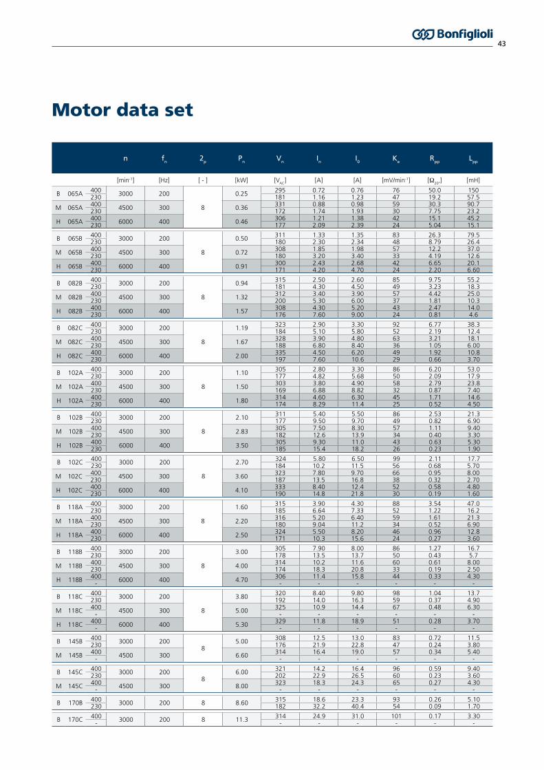
Motor data set
n fn 2p Pn Vn In I0 Ke Rpp Lpp
[min-1] [Hz] [ - ] [kW] [VAC
] [A] [A] [mV/min-1] [Ω20°
] [mH]
B 065A 400 3000 200
8
0.25 295 0.72 0.76 76 50.0 150230 181 1.16 1.23 47 19.2 57.5
M 065A 400 4500 300 0.36 331 0.88 0.98 59 30.3 90.7230 172 1.74 1.93 30 7.75 23.2
H 065A 400 6000 400 0.46 306 1.21 1.38 42 15.1 45.2230 177 2.09 2.39 24 5.04 15.1
B 065B 400 3000 200
8
0.50 311 1.33 1.35 83 26.3 79.5230 180 2.30 2.34 48 8.79 26.4
M 065B 400 4500 300 0.72 308 1.85 1.98 57 12.2 37.0230 180 3.20 3.40 33 4.19 12.6
H 065B 400 6000 400 0.91 300 2.43 2.68 42 6.65 20.1230 171 4.20 4.70 24 2.20 6.60
B 082B 400 3000 200
8
0.94 315 2.50 2.60 85 9.75 55.2230 181 4.30 4.50 49 3.23 18.3
M 082B 400 4500 300 1.32 312 3.40 3.90 57 4.42 25.0230 200 5.30 6.00 37 1.81 10.3
H 082B 400 6000 400 1.57 308 4.30 5.20 43 2.47 14.0230 176 7.60 9.00 24 0.81 4.6
B 082C 400 3000 200
8
1.19 323 2.90 3.30 92 6.77 38.3230 184 5.10 5.80 52 2.19 12.4
M 082C 400 4500 300 1.67 328 3.90 4.80 63 3.21 18.1230 188 6.80 8.40 36 1.05 6.00
H 082C 400 6000 400 2.00 335 4.50 6.20 49 1.92 10.8230 197 7.60 10.6 29 0.66 3.70
B 102A 400 3000 200
8
1.10 305 2.80 3.30 86 6.20 53.0230 177 4.82 5.68 50 2.09 17.9
M 102A 400 4500 300 1.50 303 3.80 4.90 58 2.79 23.8230 169 6.88 8.82 32 0.87 7.40
H 102A 400 6000 400 1.80 314 4.60 6.30 45 1.71 14.6230 174 8.29 11.4 25 0.52 4.50
B 102B 400 3000 200
8
2.10 311 5.40 5.50 86 2.53 21.3230 177 9.50 9.70 49 0.82 6.90
M 102B 400 4500 300 2.83 305 7.50 8.30 57 1.11 9.40230 182 12.6 13.9 34 0.40 3.30
H 102B 400 6000 400 3.50 305 9.30 11.0 43 0.63 5.30230 185 15.4 18.2 26 0.23 1.90
B 102C 400 3000 200
8
2.70 324 5.80 6.50 99 2.11 17.7230 184 10.2 11.5 56 0.68 5.70
M 102C 400 4500 300 3.60 323 7.80 9.70 66 0.95 8.00230 187 13.5 16.8 38 0.32 2.70
H 102C 400 6000 400 4.10 333 8.40 12.4 52 0.58 4.80230 190 14.8 21.8 30 0.19 1.60
B 118A 400 3000 200
8
1.60 315 3.90 4.30 88 3.54 47.0230 185 6.64 7.33 52 1.22 16.2
M 118A 400 4500 300 2.20 316 5.20 6.40 59 1.61 21.3230 180 9.04 11.2 34 0.52 6.90
H 118A 400 6000 400 2.50 324 5.50 8.20 46 0.96 12.8230 171 10.3 15.6 24 0.27 3.60
B 118B 400 3000 200
8
3.00 305 7.90 8.00 86 1.27 16.7230 178 13.5 13.7 50 0.43 5.7
M 118B 400 4500 300 4.00 314 10.2 11.6 60 0.61 8.00230 174 18.3 20.8 33 0.19 2.50
H 118B 400 6000 400 4.70 306 11.4 15.8 44 0.33 4.30- - - - - - -
B 118C 400 3000 200
8
3.80 320 8.40 9.80 98 1.04 13.7230 192 14.0 16.3 59 0.37 4.90
M 118C 400 4500 300 5.00 325 10.9 14.4 67 0.48 6.30- - - - - - -
H 118C 400 6000 400 5.30 329 11.8 18.9 51 0.28 3.70- - - - - - -
B 145B 400 3000 2008
5.00 308 12.5 13.0 83 0.72 11.5230 176 21.9 22.8 47 0.24 3.80
M 145B 400 4500 300 6.60 314 16.4 19.0 57 0.34 5.40- - - - - - -
B 145C 400 3000 2008
6.00 321 14.2 16.4 96 0.59 9.40230 202 22.9 26.5 60 0.23 3.60
M 145C 400 4500 300 8.00 323 18.3 24.3 65 0.27 4.30- - - - - - -
B 170B 400 3000 200 8 8.60 315 18.6 23.3 93 0.26 5.10230 182 32.2 40.4 54 0.09 1.70
B 170C 400 3000 200 8 11.3 314 24.9 31.0 101 0.17 3.30- - - - - - -

44
ItemMOTOR SIZE
065A... 065B 082B... 170C
RES2 RES1 RES2
Poles number 2 2 2
Transformation ratio 0.5 ±5% 0.5 +15%
-5% 0.5 ±5%
Input voltage [Vacrms
] 7 11 5.5
Input current [mA] 65 57 61
Input frequency [kHz] 10 8 10
Phase shift 0° -11° -12°
Input impedance Zro ( ) 70 + j100 75 + j185 43 + j79
Output impedance Zss (Ω) 175 +j275 135 + j265 62 + j112
Electrical error ±10’ ±10’ ±10’
Accuracy ripple 1’max 1’max 1’max
Operating temperature -55 °C... + 155 °C -55 °C... + 155 °C -55 °C... + 155 °C
Max Speed [min-1] 10000 20000 10000
Mass [kg] 0.065 0.28 0.28
Rotor Inertia [kgm2 x 10-6] 3.0 5.0 5.0
Bonfiglioli BMS Compact Servo Gearmotor series is available with different feedback devices. Available feedback devices are resolver and absolute single-turn and multi-turn encoders. All available feedback devices are supported by Bonfiglioli Vectron frequency inverter - Active Cube series.
The resolver is a passive wound device consisting of a stator and rotor elements excited from an external source. It produces two output signals that correspond to the sine and cosine angle of the motor shaft. This is a robust and accurate absolute device, capable of withstanding high temperatures and high levels of vibration. Positional information is absolute within one turn.Available absolute encoders use a high precision optical disc or a capacitive measuring principle to provide the absolute rotor position. The high resolution performed is based on a combination of absolute data, transmitted with a serial link, and incremental sine/cosine signals. The single-turn absolute encoder has an absolute positional information only within one turn while the multi turn absolute encoder is provided of extra gear wheels that account for several shaft revolution.
Feedback devices
Resolver data sheet

45
Encoder data sheet
ItemMOTOR SIZE
065A… 065B 082B… 170C
ENB1 ENB2 ENB1 ENB2
Manufacturer Dr. JOHANNES HEIDENHAIN GmbH
Data interface EnDat EnDat
Model ECN1113 EQN1125 ECN1313 EQN1325
Type Single turn Multi turn Single turn Multi turn
Measuring principle Optical Optical
Power supply 3.6 VDC... 14 VDC 3.6 VDC... 14 VDC
Current consumption 85 mA (5V) 105 mA (5V) 85 mA (5V) 105 mA (5V)
Periods per revolution 512 512 2048 2048
Position per revolution 8192 (13 bits) 8192 (13 bits) 8192 (13 bits) 8192 (13 bits)
Revolutions - 4096 (12 bits) - 4096 (12 bits)
Operating temperature -40 °C... +115 °C -40 °C... +115 °C
Max Speed [min-1] 12000 12000
Resistance to shocks 1000 m/s2 - 6 ms 2000 m/s2 - 6 ms
Resistance to vibrations 200 m/s2 - 55… 2000 Hz 300 m/s2 - 55… 2000 Hz
Mass [kg] 0.10 0.25
Rotor Inertia [kgm2 x 10-6] 0.40 2.60
ItemMOTOR SIZE
065A… 065B 082B… 170C 065A… 170C
ENB3 ENB4 ENB3 ENB4 ENB5 ENB6
Manufacturer SICK AG
Data interface Hiperface Hiperface Hiperface
Model SKS36 SKM36 SRS50 SRM50 SEK37 SEL37
Type Single turn Multi turn Single turn Multi turn Single turn Multi turn
Measuring principle Optical Optical Capacitive
Power supply 7 VDC... 12 VDC 7 VDC... 12 VDC 7 VDC... 12 VDC
Current consumption 60 mA 60 mA 80 mA 80 mA 50 mA 50 mA
Periods per revolution 128 128 1024 1024 16 16
Position per revolution 4096 (12 bits) 4096 (12 bits) 32768 (15 bit) 32768 (15 bit) 512 (9 bits) 512 (9 bits)
Revolutions - 4096 (12 bits) - 4096 (12 bits) - 4096 (12 bits)
Operating temperature -20 °C... +110 °C -30 °C... +115 °C -40 °C... +115 °C -20 °C... +115 °C
Max Speed [min-1] 10000 12000 120000
Resistance to shocks 100 g / 6 ms 100 g / 6 ms 100 g / 10 ms
Resistance to vibrations 50 g / 10… 2000 Hz 20 g / 10… 2000 Hz 50 g / 10… 2000 Hz
Mass [kg] 0.07 0.20 0.04
Rotor Inertia [kgm2 x 10-6] 0.45 1.00 0.10

46
BMS compact gear motors are equipped with a thermal protector to avoid windings temperature exceeding the limit of F insulation class (155 °C). The thermal protectors have a double insulation level. Available thermal protectors:
PTC variantA PTC thermistor rated 150˚C is placed into the motor winding. The PTC thermistor resistance curve is in accordance with DIN 44081-82.
KTY variantA KTY silicon semi-conductor resistance sensor (KTY84-130 type) is placed into the motor winding. The working temperature range is -40 °C... +260 °C.
TC1 variantA Platinum resistance temperature sensor (PT1000 type) is placed into the motor winding. The PT1000 characteristic is in accordance with IEC 60751: 2008, tolerance class B. The working temperature range is -40 °C... +250 °C.
Thermal protection

47
The BMS gear motor is available also with an electromagnetic holding brake. The brake is for use as an holding brake with motor shaft stationary. Do not use it as a dynamic brake, except for emergencies as main supply failure. The brake variant increases both length and weight of the gear motor. Please note that the brake variant is not available when the F1 flywheel/additional inertia variant is selected.
Data of the available brake for each gear motor size are summarized in the following table. The braking torque Mb refers to the motor shaft and has to be multiplied by the gearbox ratio i.
Mb 2 = Mb ∙ i
Electromechanical holding brake
Motor size Mb 20 °C Mb 100 °C Vb Ib Pb 20 °C Jb Δmb t1 t2
Nm Nm Vdc A W Kg cm2 kg ms ms
065A2.0 1.8
24
0.46 11 0.07 0.2 6 25065B
082A4.5 4.0 0.50 12 0.18 0.6 7 35
082B
102A
9.0 8.0 0.75 18 0.54 1.1 7 40102B
102C
118A
18 15 1.0 24 1.66 2.2 10 50118B
118C
145B18 15 1.0 24 1.66 2.6 10 50
145C
170B36 32 1.1 26 5.56 4.5 22 90
170C
Additional flywheel / inertiaBMS compact servo gear motor series is provided optionally with additional flywheel / inertia (F1 variant). The additional flywheel / inertia variant increases both length and weight of the gear motor.
Motor size JJ ΔmJ
Kg cm2 kg
065A0.5 0.4
065B
082B3.0 1.0
082C
102A
7.5 1.7102B
102C
118A
16 3.5118B
118C
145B36 5.0
145C
170B70 8.2
170C
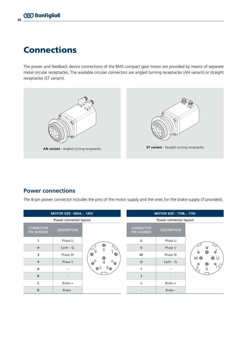
48
The power and feedback device connections of the BMS compact gear motor are provided by means of separate metal circular receptacles. The available circular connectors are angled turning receptacles (AN variant) or straight receptacles (ST variant).
Connections
MOTOR SIZE - 065A… 145C
Power connector layout
CONNECTORPIN NUMBER
DESCRIPTION
3
D
C B
4
1
A
1 Phase U
Earth - SL
3 Phase W
4 Phase V
A -
B -
C Brake +
D Brake -
MOTOR SIZE - 170B... 170C
Power connector layout
CONNECTORPIN NUMBER
DESCRIPTION
V
W U
- +
2 1
U Phase U
V Phase V
W Phase W
Earth - SL
1 -
2 -
+ Brake +
- Brake -
AN variant - Angled turning receptacles ST variant - Straight turning receptacles
Power connectionsThe 8-pin power connector includes the pins of the motor supply and the ones for the brake supply (if provided).

49
Signal connectionsThe signal connector gathers the feedback device signals and the thermal protection terminals. Each feedback device, resolver or encoder has a proper signal connector layout.
RESOLVER (RES1/RES2)Signal connector layout
CONNECTOR PIN NUMBER DESCRIPTION
87
12
611
53
4
102
91
1 Sin -2 Sin +3 n.c.4 Shield cable 5 n.c.6 n.c.7 Exct -8 PTC / KTY / PT1000 -9 PTC / KTY / PT1000 +10 Exct +11 Cos +12 Cos -
ENCODER WITH ENDAT INTERFACE (ENB1/ENB2)Signal connector layout
CONNECTOR PIN NUMBER DESCRIPTION
1
2
3
4
567
8
9
10
11
1213
141716
15
1 UP SENSOR2 n.c.3 n.c.4 0V SENSOR5 PTC / KTY / PT1000 -6 PTC / KTY / PT1000 +7 UP8 Clock +9 Clock -10 0V11 Shield cable 12 B +13 B -14 DATA +15 A +16 A -17 DATA -
ENCODER WITH HIPERFACE INTERFACE (ENB3/ENB4/ENB5/ENB6)Signal connector layout
CONNECTOR PIN NUMBER DESCRIPTION
1
2
3
4
567
8
9
10
11
1213
141716
15
1 Sin +2 Sin -3 RS485 +4 n.c.5 Shield cable 6 n.c.7 GND (0V)8 PTC / PT1000 -9 PTC / PT1000 +
10 + Vdc11 Cos +12 Cos -13 RS485 -14 n.c.15 n.c.16 n.c.17 n.c.

50
Cables for power supply and feedback device complete the offer of the BMS compact servo gear motor. Three standard cable lengths available (3m, 5m and 10 m). Custom lengths on request.
Cables
SERVO GEAR MOTOR INVERTER
SIGNAL cable (green)
POWER cable (orange)
Power cablesPower cables can be recognized by the orange colour according to Desina standard. The conductors cross-section depends on the motor nominal current.The power cable terminates on the inverter side with flying leads covered by ferrules for connections with screw terminals. On the motor side, the power cable is equipped with a metal circular plug with bayonet technology for an easy and sure connection.
The power cables fulfil the following technical requirements:
Technical Data
Properties Oil resistant shielded cable for dynamic laying
ConductorTinned Stranded Cu wire complying with IEC 60228 Cl 5 / 6
Outer SheathPUR or equivalent thermoplastic material Colour: orange RAL 2003
Inner Sheath PP or TPE
Tinned Cu braided Shield
Coverage overall screen > 80%
Electrical Data
Nom. Volt. Power cores U0/U 600/1000V
Nom. Volt. Control cores U0/U 300/500V
AC Test Volt. Power cores 4 kV
AC Test Volt. Control cores 1 kV
Insulation Resistance > 5 MOhm/km
Mechanical Data
Service Temperature -15 / +80 °C
Minimum Bending Radius 10 x Cable diameter
N° bending cycles ≥ 106
Max Speed ≥ 180 m/min
Max Acceleration ≥ 15 m/s2
Inverter side Motor side

51
The cable ordering code comprises five fields as follows:
Standard and Certifications
UL/CSA, RoHS, DESINA
Cable length03 3 m05 5 m10 10 m
Phase wire section015 1.5 mm2
025 2.5 mm2
040 4 mm2
100 10 mm2
Brake wiresNB Without brake wiresB With brake wires
Connector size and typeC3 8-pin connector, motor with feedback, sizes 65... 145C4 8-pin connector, motor with feedback, size 170
MPC C3153 NB
The following table shows the suggested combination of power cable designation and motor size according to the selected overspeed and nominal voltage supply. Field XX refers to the cable length (03, 05, 10), while field YY refers to the brake variant (NB, B): see previous page for fields description.
MOTOR SIZE 400V NOMINAL VOLTAGE OVERSPEED 230V NOMINAL VOLTAGE OVERSPEED
BASE MEDIUM HIGH BASE MEDIUM HIGH
065A
065B
082B
082C MPC XX 015 YY C3
102A MPC XX 015 YY C3
102B
102C MPC XX 025 YY C3 MPC XX 040 YY C3
118A
118B MPC XX 025 YY C3
118C MPC XX 025 YY C3MPC XX 040 YY C3
145BMPC XX 040 YY C3
145C MPC XX 040 YY C3
Not available170B MPC XX 040 YY C4Not available
MPC XX 100 YY C4
170C MPC XX 100 YY C4

52
Feedback deviceInverter side termination
Inverter feedback module
Cable length
3 m 5m 10 m
RES1 / RES2Flying leads
EM-RES-01/02EM-AUT-01/04
MSC 03 RES FW MSC 05 RES FW MSC 10 RES FW
SUB-D9 EM-RES-03 MSC 03 RES SC MSC 05 RES SC MSC 10 RES SC
ENB1 / ENB2HD SUB-D15
EM-ABS-01EM-AUT-01
MSC 03 EN1 SC MSC 05 EN1 SC MSC 10 EN1 SC
Flying leads - MSC 03 EN1 FW MSC 05 EN1 FW MSC 10 EN1 FW
ENB3 / ENB4 ENB5 / ENB6
SUB-D15EM-ABS-01EM-AUT-01
MSC 03 EN3 SC MSC 05 EN3 SC MSC 10 EN3 SC
Flying leads - MSC 03 EN3 FW MSC 05 EN3 FW MSC 10 EN3 FW
The ordering codes of the signal cables are described in the following table:
The signal cables fulfil the following technical requirements:
Technical Data
Properties Oil resistant shielded cable for dynamic laying
ConductorTinned Stranded Cu wire complying with IEC 60228 Cl 5 / 6
Outer SheathPUR or equivalent thermoplastic material Colour: green RAL 6018
Inner Sheath PP or TPE
Tinned Cu braided Shield
Coverage overall screen > 80%
Electrical Data
Nominal Voltage 30 V
AC Test Voltage 1500 V
Insulation Resistance > 10 MOhm/km
Capacitance strand/strand < 150 pF/m
Standard and Certifications
UL/CSA, RoHS, DESINA
Mechanical Data
Service Temperature -20 / +80 °C
Minimum Bending Radius 10 x Cable diameter
N° bending cycles ≥ 106
Max Speed ≥ 180 m/min
Max Acceleration ≥ 15 m/s2
Inverter side Motor side
Cables
Signal cablesSignal cables are recognizable by the green colour according to Desina standard. The conductors number, their cross-section and their terminal type depend on the transducer typology supported by the cable.Cables are available for connection for every feedback option. On the motor side, the power cable is equipped with a metal circular plug with bayonet technology for an easy and sure connection.On the inverter side, the cable end can be executed with two different terminations:• with SUB-D male connector for connection with corresponding SUB-D female of the module interface.• with ferrules for connection to screw terminals of the module interface.Connections layouts are dedicated to Bonfiglioli Vectron interface modules.
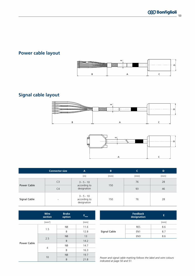
53
Power and signal cable marking follows the label and wire colours indicated at page 50 and 51.
E
D
AB C
E
E
DD
A
A
B C
C
Connector size A B C D
[m] [mm] [mm] [mm]
Power CableC3 3 - 5 - 10
according to designation
15076 28
C4 93 46
Signal Cable -3 - 5 - 10
according to designation
150 76 28
Wiresection
Brakeoption
Emax
[mm2] [mm]
Power Cable
1.5NB 11.6
B 12.8
2.5NB 13
B 14.2
4NB 14.7
B 16.3
10NB 19.7
B 21.8
Feedbackdesignation
E
[mm]
Signal Cable
RES 8.6
EN1 8.7
EN3 8.6
Power cable layout
Signal cable layout

54
Cables
Plugs
Cable designation Plug order code Description Manufacturer code
MPC XX 015 YY C3MPC XX 025 YY C3
712692074TE CONNECTIVITY 923 Series - M23 8-pin power connector Pin crimping range: 4 x (0.35-2.5 mm2) + 4 x (0.14-1 mm2)
B ST A 078 FR 48 48 0100 000
MPC XX 040 YY C3 712692081TE CONNECTIVITY 923 Series - M23 8-pin power connector Pin crimping range: 4 x (2.5-4 mm2) + 4 x (0.14-1 mm2)
B ST A 078 FR 45 59 0100 000
MPC XX 100 YY C4 712692080TE CONNECTIVITY 940 Series - M40 8-pin power connector Pin crimping range: 4 x (1.5-10 mm2) + 4 x (0.35-2.5 mm2)
C ST A 264 FR 48 45 0020 000
MSC XX RES YY 712692053TE CONNECTIVITY 623 Series - M23 12-pin signal connector Pin crimping range: 12 x (0.14-1 mm2)
A ST A 021 FR 11 41 0100 000
MSC XX EN1 YYMSC XX EN3 YY
712692063TE CONNECTIVITY 623 Series - M23 17-pin signal connector Pin crimping range: 17 x (0.14-1 mm2)
A ST A 035 FR 11 41 0100 000
See previous pages for descriptions of XX and YY fields. Plugs are provided with a complete set of pins.

55
Combinations BMS -> Inverter
Suggested combinations of BMS gear motor and Bonfiglioli Vectron Active Cube Inverter.
BMS Gear Motor Not Overload Applications Overload Applications
Variants Motor parameters
Selection Criteria
Motor Inverter Motor InverterI0
< In
I0
< In
andImax
< Ipk
Overspeed Motor sizeSupply AC
voltagePm Imax I0
Inverter Rated Current Bonfiglioli Vectron
ACU Inverter Size
Inverter Long-Term Overlo-ad Current (60s) Bonfiglioli Vectron
ACU Inverter SizeIn Ipk
[V] [kW] [A] [A] [A] [A]
B 065A400
0.252.43 0.76 1 ACU 410 01 3.2 ACU 410 03
230 3.9 1.23 1.6 ACU 210 01 5 ACU 210 03
M 065A400
0.363.1 0.98 1 ACU 410 01 3.2 ACU 410 03
230 6.2 1.93 2.5 ACU 210 03 7.3 ACU 210 09
H 065A400
0.464.4 1.38 1.6 ACU 410 03 4.8 ACU 410 09
230 7.7 2.39 2.5 ACU 210 03 10.5 ACU 210 11
B 065B400
0.54.6 1.35 1.6 ACU 410 03 4.8 ACU 410 09
230 8.0 2.34 2.5 ACU 210 03 10.5 ACU 210 11
M 065B400
0.726.7 1.98 2.4 ACU 410 07 8.7 ACU 410 13
230 11.5 3.4 4 ACU 210 07 14.3 ACU 210 13
H 065B400
0.919.1 2.68 3.2 ACU 410 09 11.7 ACU 410 15
230 15.9 4.7 5.5 ACU 210 09 16.2 ACU 210 15
B 082B400
0.948.9 2.6 3.2 ACU 410 09 11.7 ACU 410 15
230 15.5 4.5 5.5 ACU 210 09 16.2 ACU 210 15
M 082B400
1.3213.2 3.9 4.2 ACU 410 12 13.5 ACU 410 18
230 20.6 6.0 7 ACU 210 11 26.2 ACU 210 18
H 082B400
1.5717.7 5.2 5.8 ACU 410 13 21 ACU 410 19
230 31 9 9.5 ACU 210 13 44.5 ACU 210 21
B 082C400
1.199.9 3.3 3.8 ACU 410 11 11.7 ACU 410 15
230 17.4 5.8 7 ACU 210 11 26.2 ACU 210 18
M 082C400
1.6714.4 4.8 5.8 ACU 410 13 21 ACU 410 19
230 25.1 8.4 9.5 ACU 210 13 26.2 ACU 210 18
H 082C400
218.6 6.2 7.8 ACU 410 15 21 ACU 410 19
230 32 10.6 12.5 ACU 210 15 44.5 ACU 210 21
B 102A400
1.110.2 3.3 3.8 ACU 410 11 11.7 ACU 410 15
230 17.6 5.68 7 ACU 210 11 26.2 ACU 210 18
M 102A400
1.515 4.9 5.8 ACU 410 13 21 ACU 410 19
230 27.3 8.82 9.5 ACU 210 13 30.3 ACU 210 19
H 102A400
1.819 6.3 7.8 ACU 410 15 21 ACU 410 19
230 35.1 11.4 12.5 ACU 210 15 44.5 ACU 210 21
B 102B400
2.120 5.5 5.8 ACU 410 13 21 ACU 410 19
230 35 9.7 12.5 ACU 210 15 44.5 ACU 210 21
M 102B400
2.8330 8.3 9 ACU 410 18 30.3 ACU 410 22
230 51 13.9 18 ACU 210 18 51.5 ACU 210 22
H 102B400
3.540 11 14 ACU 410 19 44.5 ACU 410 25
230 66 18.2 22 ACU 210 19 -
B 102C400
2.721 6.5 7.8 ACU 410 15 21 ACU 410 19
230 37 11.5 12.5 ACU 210 15 44.5 ACU 210 21
M 102C400
3.631 9.7 14 ACU 410 19 37.5 ACU 410 23
230 54 16.8 18 ACU 210 18 -
H 102C400
4.140 12.4 14 ACU 410 19 44.5 ACU 410 25
230 70 21.8 22 ACU 210 19 -
B 118A400
1.614 4.3 5.8 ACU 410 13 21 ACU 410 19
230 23.9 7.33 9.5 ACU 210 13 26.2 ACU 210 18
M 118A400
2.221 6.4 7.8 ACU 410 15 21 ACU 410 19
230 36.5 11.2 12.5 ACU 210 15 44.5 ACU 210 21
H 118A400
2.527 8.2 9 ACU 410 18 30.3 ACU 410 22
230 50.8 15.62 18 ACU 210 18 51.5 ACU 210 22
B 118B400
328 8 9 ACU 410 18 30.3 ACU 410 22
230 48 13.7 18 ACU 210 18 51.5 ACU 210 22
M 118B400
440 11.6 14 ACU 410 19 44.5 ACU 410 25
230 73 20.8 22 ACU 210 19 -
H 118B400
4.755 15.8 18 ACU 410 21 60 ACU 410 27
- - - - -
B 118C400
3.832 9.8 14 ACU 410 19 37.5 ACU 410 23
230 53 16.3 18 ACU 210 18 -
M 118C400
547 14.4 18 ACU 410 21 60 ACU 410 27
- - - - -
H 118C400
5.362 18.9 22 ACU 410 22 67.5 ACU 410 29
- - - - -
B 145B400
550 13 14 ACU 410 19 60 ACU 410 27
230 88 22.8 32 ACU 210 21 -
M 145B400
6.673 19 22 ACU 410 22 90 ACU 410 31
- - - - -
B 145C400
654 16.4 18 ACU 410 21 60 ACU 410 27
230 87 26.5 32 ACU 210 21 -
M 145C400
880 24.3 25 ACU 410 23 90 ACU 410 31
- - - - -
B 170B400
8.670 23.3 25 ACU 410 23 90 ACU 410 31
230 121 40.4 - -
B 170C400
11.396 31 32 ACU 410 25 112.5 ACU 410 33
- - - - -

56
Bonfiglioli is located in regions and countries around the world that enable us to provide faster sales and service to customers.
We are around the world, and around the corner.
Bonfiglioli worldwide presence
ITALY
GERMANYFRANCE TURKEYUNITED KINGDOMSPAINBRAZIL USA SLOVAKIA CHINASINGAPORE
SOUTH AFRICA AUSTRALIAVIETNAM NEW ZEALANDINDIA
HEADQUARTERS
BRANCHES
PRODUCTION FACILITIES
BRAZIL SPAIN FRANCE
NEW ZEALANDAUSTRALIAVIETNAMINDIASOUTH AFRICAITALY
GERMANY SLOVAKIA TURKEY SINGAPORE CHINAUNITED KINGDOMUSA
21 BRANCH OFFICES IN 15 COUNTRIES
WORLDWIDEDISTRIBUTION
NETWORK
LOCAL SUPPORTSales, Customer Service, Warranty, Tech support,
Spare parts

57
Customer satisfaction has always been one of Bonfiglioli’s key values. It is pursued around the
world, and in a wide range of contexts, by a network of subsidiaries located in 17 countries
and on 5 continents.
Each subsidiary provides rapid and efficient pre-sales and after-sales service, and can guarantee prompt deliveries
from local assembly plant and warehouses.
In addition to our directly controlled subsidiaries, Bonfiglioli can also rely on an extensive network of authorised
dealers, selected for their ability to guarantee excellent pre-sales and after-sales assistance.
To give everybody the chance to purchase a Bonfiglioli product - anywhere.
This is the ambitious objective that drives the development of our added-value sales networks, off and on-line.
BEST (Bonfiglioli Excellence Service Team) is one of the most modern sales organisations in the field of power
transmission.
Our BEST partners can benefit from our local assembly plant and warehouses, our training courses and tools, and
our promotional activities.
For the first time ever, manufacturer and distributors are working together from the product assembly stage and
in the design of new applications, in a sharing process that sees one party transferring know-how and technology
and the other partly providing a thorough knowledge of the local market.
Bonfiglioli is your partner worldwide for power transmission and motion control
Bonfiglioli is located in regions and countries around the world that enable us to provide faster sales and service to customers.
We are around the world, and around the corner.
Bonfiglioli worldwide presence
ITALY
GERMANYFRANCE TURKEYUNITED KINGDOMSPAINBRAZIL USA SLOVAKIA CHINASINGAPORE
SOUTH AFRICA AUSTRALIAVIETNAM NEW ZEALANDINDIA
HEADQUARTERS
BRANCHES
PRODUCTION FACILITIES
BRAZIL SPAIN FRANCE
NEW ZEALANDAUSTRALIAVIETNAMINDIASOUTH AFRICAITALY
GERMANY SLOVAKIA TURKEY SINGAPORE CHINAUNITED KINGDOMUSA
21 BRANCH OFFICES IN 15 COUNTRIES
WORLDWIDEDISTRIBUTION
NETWORK
LOCAL SUPPORTSales, Customer Service, Warranty, Tech support,
Spare parts

58
BR_C
AT_
BMS_
STD
_EN
G_R
00_0
New Zealand www.bonfiglioli.co.nz 88 Hastie Avenue, Mangere Bridge, 2022 Auckland PO Box 11795, Ellerslie Tel. +64 09 634 6441
Singapore www.bonfiglioli.com 24 Pioneer Crescent #02-08 West Park Bizcentral - Singapore, 628557 Tel. +65 6268 9869
Slovakia www.bonfiglioli.com Robotnícka 2129 Považská Bystrica, 01701 Slovakia Tel. +421 42 430 75 64
South Africa www.bonfiglioli.co.za 55 Galaxy Avenue, Linbro Business Park - Sandton Tel. +27 11 608 2030
Spain www.tecnotrans.bonfiglioli.com Tecnotrans Bonfiglioli S.A. Pol. Ind. Zona Franca, Sector C, Calle F, nº 6 08040 Barcelona Tel. +34 93 447 84 00
Turkey www.bonfiglioli.com.tr Atatürk Organize Sanayi Bölgesi, 10007 Sk. No. 30 Atatürk Organize Sanayi Bölgesi, 35620 Çigli - Izmir Tel. +90 0 232 328 22 77
United Kingdom www.bonfiglioli.co.uk Industrial Unit 7, Colemeadow Road North Moons Moat - Redditch, Worcestershire B98 9PB Tel. +44 1527 65022 Mobile, Wind 3 - 7 Grosvenor Grange, Woolston Warrington - Cheshire WA1 4SF Tel. +44 1925 852667
USA www.bonfiglioliusa.com 3541 Hargrave Drive Hebron, Kentucky 41048 Tel. +1 859 334 3333
Vietnam www.bonfiglioli.vn Lot C-9D-CN My Phuoc Industrial Park 3 Ben Cat - Binh Duong Province Tel. +84 650 3577411
Australia www.bonfiglioli.com.au 2, Cox Place Glendenning NSW 2761 Locked Bag 1000 Plumpton NSW 2761 Tel. + 61 2 8811 8000
Brazil www.bonfigliolidobrasil.com.br Travessa Cláudio Armando 171 Bloco 3 - CEP 09861-730 - Bairro Assunção São Bernardo do Campo - São Paulo Tel. +55 11 4344 2322
China www.bonfiglioli.cn Bonfiglioli Drives (Shanghai) Co., Ltd. #68, Hui-Lian Road, QingPu District, 201707 Shanghai Tel. +86 21 6700 2000
France www.bonfiglioli.fr 14 Rue Eugène Pottier Zone Industrielle de Moimont II - 95670 Marly la Ville Tel. +33 1 34474510
Germany www.bonfiglioli.de Bonfiglioli Deutschland GmbH Sperberweg 12 - 41468 Neuss Tel. +49 0 2131 2988 0 Bonfiglioli Vectron MDS GmbH Europark Fichtenhain B6 - 47807 Krefeld Tel. +49 0 2151 8396 0 O&K Antriebstechnik Ruhrallee 8-12 - 45525 Hattingen Tel. +49 0 2324 2050 1
India www.bonfiglioli.in Mobile, Wind Bonfiglioli Transmissions Pvt. Ltd. Plot No. AC7-AC11, SIDCO Industrial Estate, Thirumudivakkam - 600 044 Chennai Tel. +91 44 2478 1035 Industrial Survey No. 528, Porambakkam High Road, Mannur Village, Sriperambudur Taluk - 602 105 Chennai Tel. +91 44 6710 3800 Plot No. A-95, Phase IV, MIDC Chakan, Village Nighoje Pune, Maharashtra - 410 501
Italy www.bonfiglioli.it Headquarters Bonfiglioli Riduttori S.p.A. Via Giovanni XXIII, 7/A Lippo di Calderara di Reno - 40012 Bologna Tel. +39 051 647 3111 Mobile, Wind Via Enrico Mattei, 12 Z.I. Villa Selva - 47100 Forlì Tel. +39 0543 789111 Industrial Via Bazzane, 33/A - 40012 Calderara di Reno Tel. +39 051 6473111 Via Trinità, 1 - 41058 Vignola Tel. +39 059 768511 Via Sandro Pertini lotto 7b - 20080 Carpiano Tel. +39 02 985081 Bonfiglioli Mechatronic Research Via F. Zeni 8 - 38068 Rovereto Tel. +39 0464 443435/36
Bonfiglioli worldwide locations


HEADQUARTERSBonfiglioli Riduttori S.p.A.Via Giovanni XXIII, 7/A40012 Lippo di Calderara di RenoBologna (Italy)tel: +39 051 647 3111fax: +39 051 647 [email protected]
We have a relentless commitment to excellence, innovation and sustainability. Our team creates, distributes and services world-class power transmission and drive solutions to keep the world in motion.