Embed Size (px)
Citation preview
Power system Protection Part – 5 Dr.Prof. Mohammed Tawfeeq
99
Power System Protection
Overcurrent Protective Relays
Dr.Professor Mohammed Tawfeeq Lazim Alzuhairi
Power system Protection Part – 5 Dr.Prof. Mohammed Tawfeeq
011
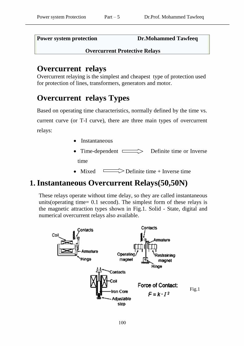
Power system protection Dr.Mohammed Tawfeeq
Overcurrent Protective Relays
Overcurrent relays Overcurrent relaying is the simplest and cheapest type of protection used
for protection of lines, transformers, generators and motor.
Overcurrent relays Types
Based on operating time characteristics, normally defined by the time vs.
current curve (or T-I curve), there are three main types of overcurrent
relays:
Instantaneous
Time-dependent Definite time or Inverse
time
Mixed Definite time + Inverse time
1. Instantaneous Overcurrent Relays(50,50N)
These relays operate without time delay, so they are called instantaneous
units(operating time= 0.1 second). The simplest form of these relays is
the magnetic attraction types shown in Fig.1. Solid - State, digital and
numerical overcurrent relays also available.
Fig.1
Power system Protection Part – 5 Dr.Prof. Mohammed Tawfeeq
010
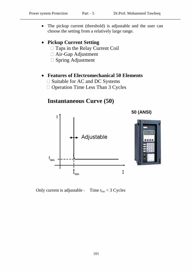
The pickup current (threshold) is adjustable and the user can
choose the setting from a relatively large range.
Pickup Current Setting
� Taps in the Relay Current Coil
� Air-Gap Adjustment
� Spring Adjustment
Features of Electromechanical 50 Elements
� Suitable for AC and DC Systems
� Operation Time Less Than 3 Cycles
Instantaneous Curve (50)
50 (ANSI)
Only current is adjustable - Time tins < 3 Cycles
Power system Protection Part – 5 Dr.Prof. Mohammed Tawfeeq
011
2. Time Overcurrent Relays Time overcurrent relays operate with a time delay. The time
delay is adjustable. The minimum current at which the relay
operates (pick up current) is also adjustable.
There are five different types of time over-current relays. Their
time-current characteristic curves are:
Definite time
Inverse-time:
Moderately inverse
Inverse (Normal)
Very inverse
Extremely inverse
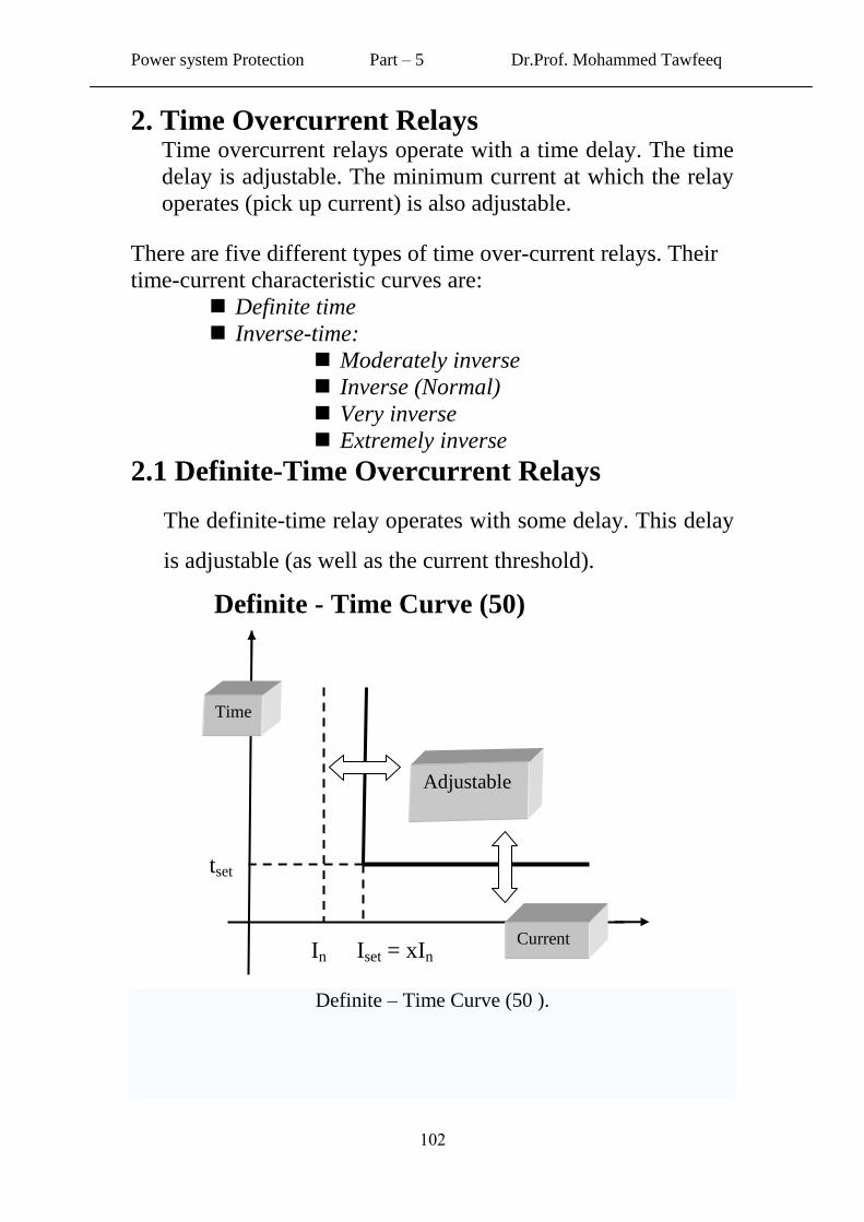
2.1 Definite-Time Overcurrent Relays
The definite-time relay operates with some delay. This delay
is adjustable (as well as the current threshold).
Definite - Time Curve (50)
Definite – Time Curve (50 ).
tset
Iset = xIn In
Time
Current
Adjustable
Power system Protection Part – 5 Dr.Prof. Mohammed Tawfeeq
011
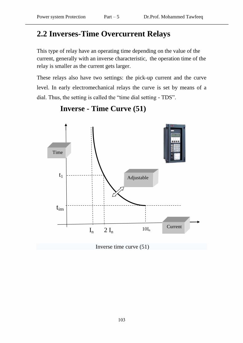
2.2 Inverses-Time Overcurrent Relays
This type of relay have an operating time depending on the value of the
current, generally with an inverse characteristic, the operation time of the
relay is smaller as the current gets larger.
These relays also have two settings: the pick-up current and the curve
level. In early electromechanical relays the curve is set by means of a
dial. Thus, the setting is called the “time dial setting - TDS”.
Inverse - Time Curve (51)
Inverse time curve (51)
In
2 In
10In
t1
tins
Time
Current
Adjustable
Power system Protection Part – 5 Dr.Prof. Mohammed Tawfeeq
011
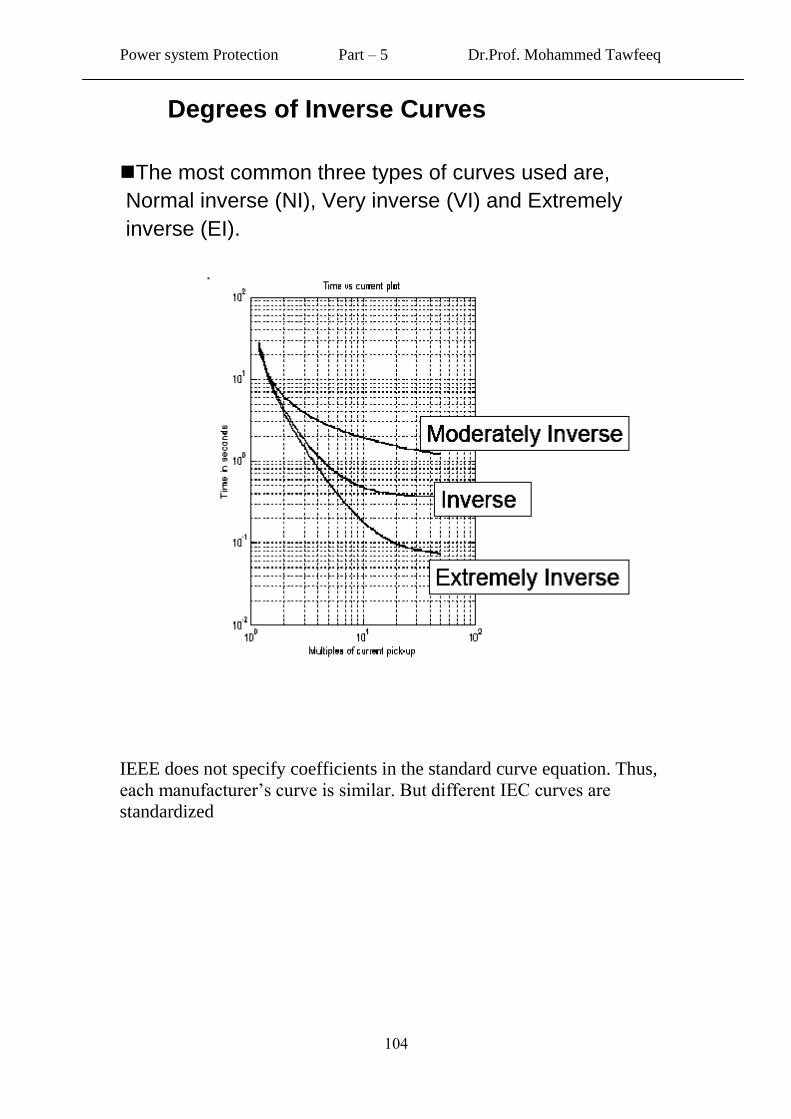
Degrees of Inverse Curves
The most common three types of curves used are,
Normal inverse (NI), Very inverse (VI) and Extremely
inverse (EI).
IEEE does not specify coefficients in the standard curve equation. Thus,
each manufacturer’s curve is similar. But different IEC curves are
standardized
Power system Protection Part – 5 Dr.Prof. Mohammed Tawfeeq
011
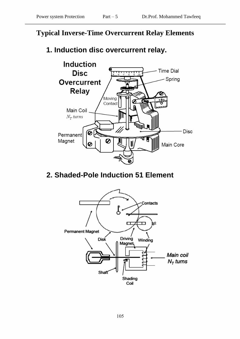
Typical Inverse-Time Overcurrent Relay Elements
1. Induction disc overcurrent relay.
2. Shaded-Pole Induction 51 Element
Power system Protection Part – 5 Dr.Prof. Mohammed Tawfeeq
011
Overcurrent Relay Setting
50 Elements: Pickup Setting
51 Elements Pickup setting
Time delay setting
definite time: time setting
inverse time: curve selection
Selecting an Overcurrent Relay Time Curve
According to American Standrd
Time-overcurrent relays (ANSI 51 relays) have two basic
settings:
the pickup current and the time delay settings.
The process for determining the time delay setting involves:
(1) Calculation of a time delay value in definite-time
overcurrent elements
(2) Selection in inverse-time overcurrent elements of a time-
current curve from a family of curves.
Note: Instantaneous over current (50) elements have only one
setting: the pickup current.
Power system Protection Part – 5 Dr.Prof. Mohammed Tawfeeq
011
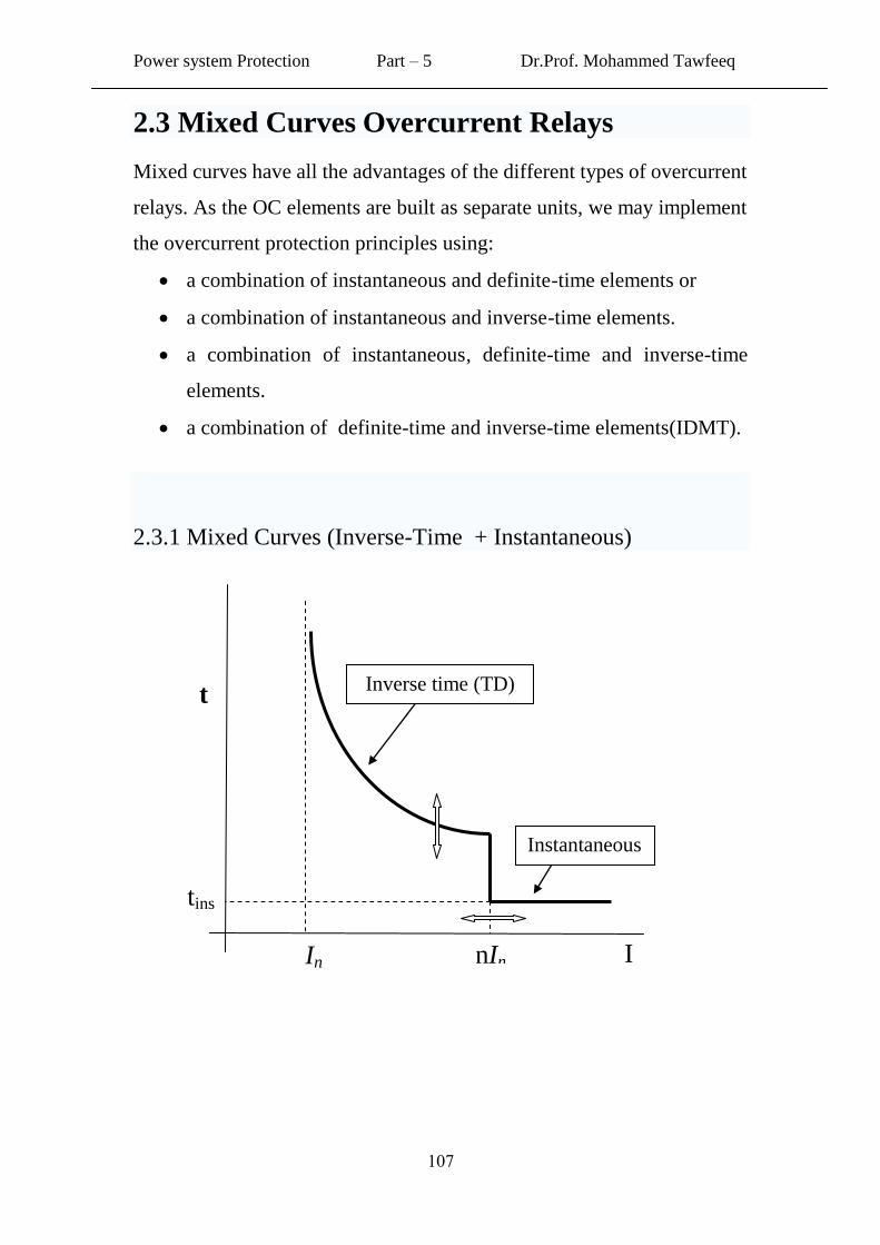
2.3 Mixed Curves Overcurrent Relays
Mixed curves have all the advantages of the different types of overcurrent
relays. As the OC elements are built as separate units, we may implement
the overcurrent protection principles using:
a combination of instantaneous and definite-time elements or
a combination of instantaneous and inverse-time elements.
a combination of instantaneous, definite-time and inverse-time
elements.
a combination of definite-time and inverse-time elements(IDMT).
2.3.1 Mixed Curves (Inverse-Time + Instantaneous)
Inverse time (TD)
Instantaneous
tins
In nIn I
t
Power system Protection Part – 5 Dr.Prof. Mohammed Tawfeeq
011
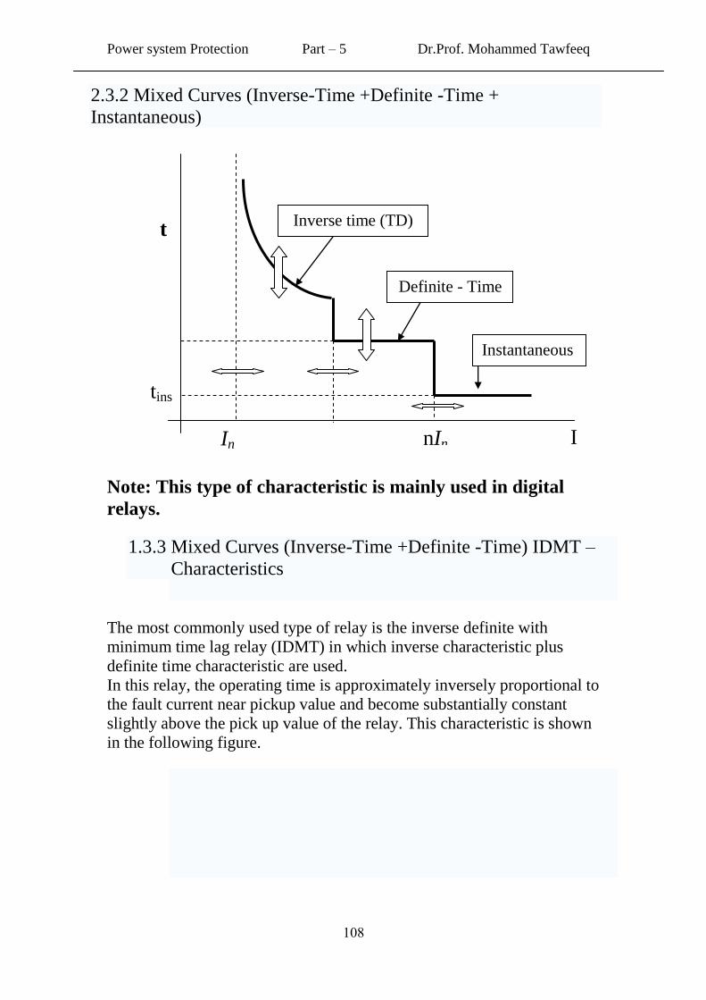
2.3.2 Mixed Curves (Inverse-Time +Definite -Time +
Instantaneous)
Note: This type of characteristic is mainly used in digital
relays.
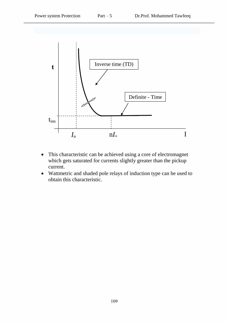
1.3.3 Mixed Curves (Inverse-Time +Definite -Time) IDMT –
Characteristics
The most commonly used type of relay is the inverse definite with
minimum time lag relay (IDMT) in which inverse characteristic plus
definite time characteristic are used.
In this relay, the operating time is approximately inversely proportional to
the fault current near pickup value and become substantially constant
slightly above the pick up value of the relay. This characteristic is shown
in the following figure.
Inverse time (TD)
Instantaneous
tins
In nIn I
t
Definite - Time
Power system Protection Part – 5 Dr.Prof. Mohammed Tawfeeq
019
This characteristic can be achieved using a core of electromagnet
which gets saturated for currents slightly greater than the pickup
current.
Wattmetric and shaded pole relays of induction type can be used to
obtain this characteristic.
Inverse time (TD)
tins
In nIn I
t
Definite - Time
Power system Protection Part – 5 Dr.Prof. Mohammed Tawfeeq
001
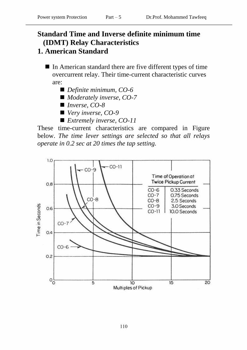
Standard Time and Inverse definite minimum time
(IDMT) Relay Characteristics
1. American Standard
In American standard there are five different types of time
overcurrent relay. Their time-current characteristic curves
are:
Definite minimum, CO-6
Moderately inverse, CO-7
Inverse, CO-8
Very inverse, CO-9
Extremely inverse, CO-11
These time-current characteristics are compared in Figure
below. The time lever settings are selected so that all relays
operate in 0.2 sec at 20 times the tap setting.
Typical time curves for CO-8 American overcurrent
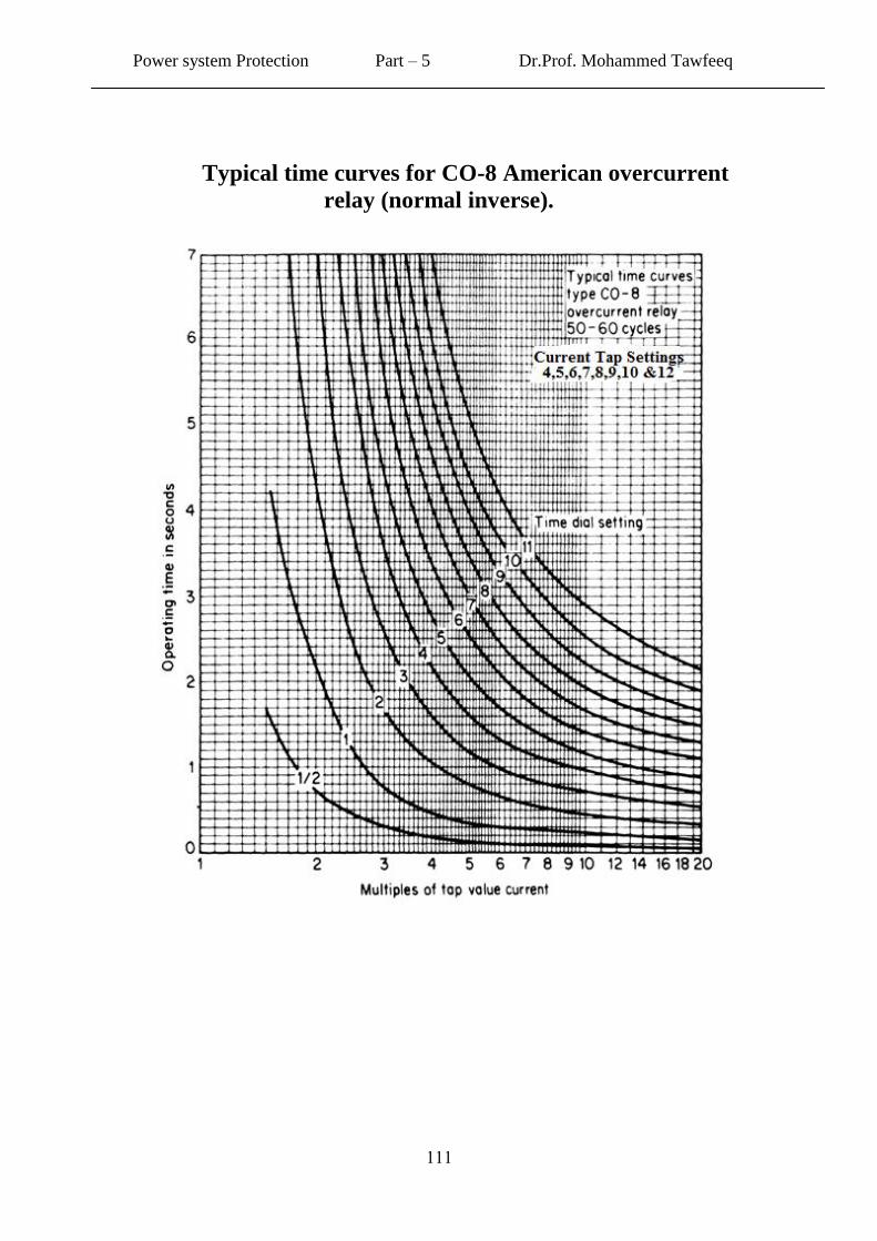
Power system Protection Part – 5 Dr.Prof. Mohammed Tawfeeq
000
Typical time curves for CO-8 American overcurrent
relay (normal inverse).
Power system Protection Part – 5 Dr.Prof. Mohammed Tawfeeq
001
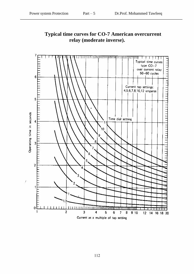
Typical time curves for CO-7 American overcurrent
relay (moderate inverse).
Power system Protection Part – 5 Dr.Prof. Mohammed Tawfeeq
001
2. IEC and British Standards
In IEC and BS Standards, we have three curves that one can
use:
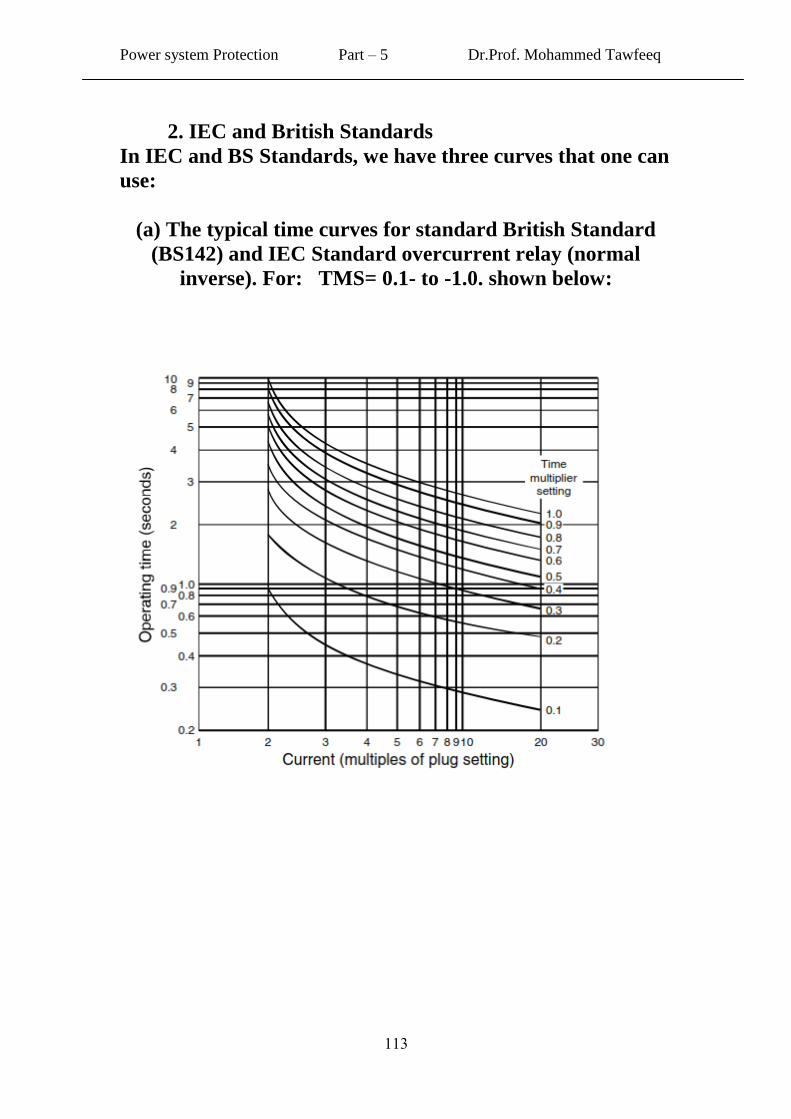
(a) The typical time curves for standard British Standard
(BS142) and IEC Standard overcurrent relay (normal
inverse). For: TMS= 0.1- to -1.0. shown below:
Power system Protection Part – 5 Dr.Prof. Mohammed Tawfeeq
001
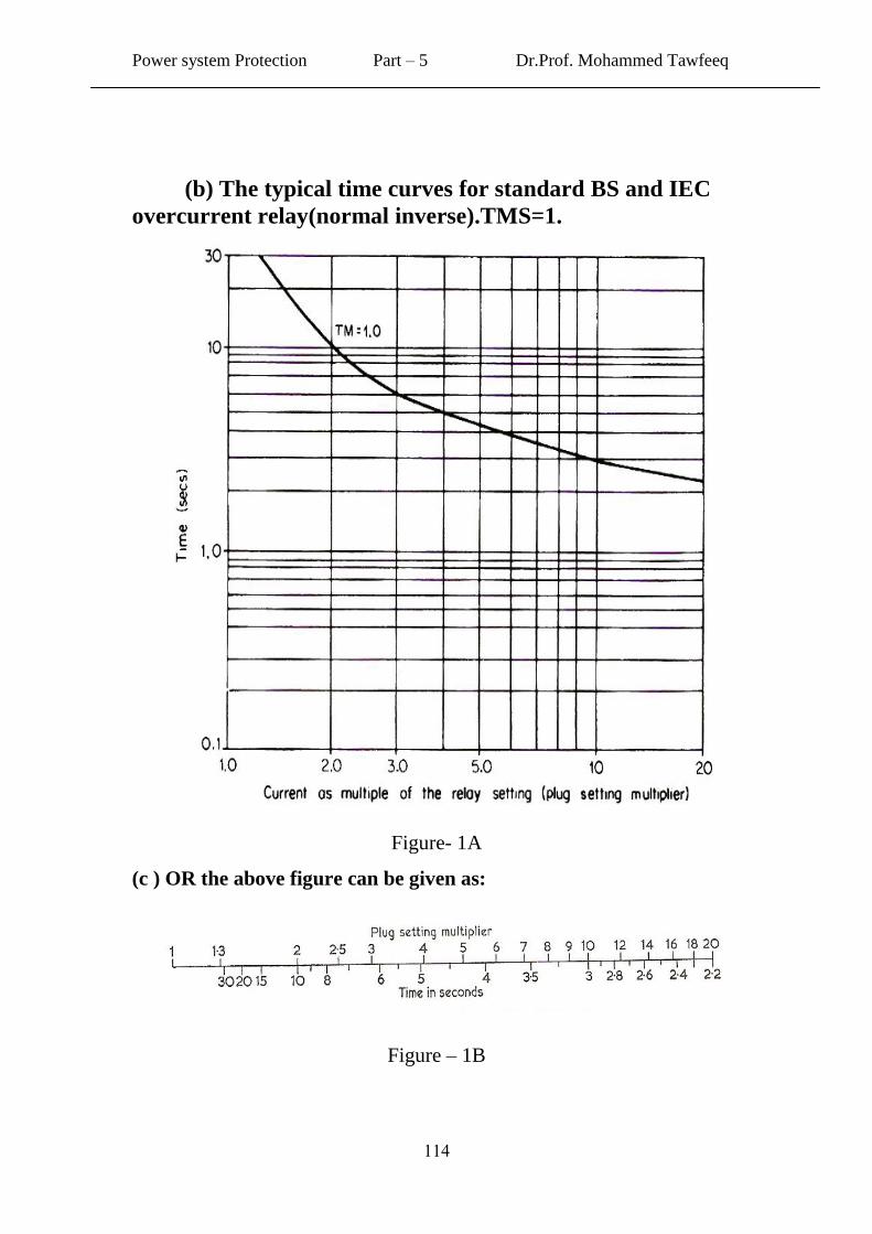
(b) The typical time curves for standard BS and IEC
overcurrent relay(normal inverse).TMS=1.
Figure- 1A
(c ) OR the above figure can be given as:
Figure – 1B
Power system Protection Part – 5 Dr.Prof. Mohammed Tawfeeq
001
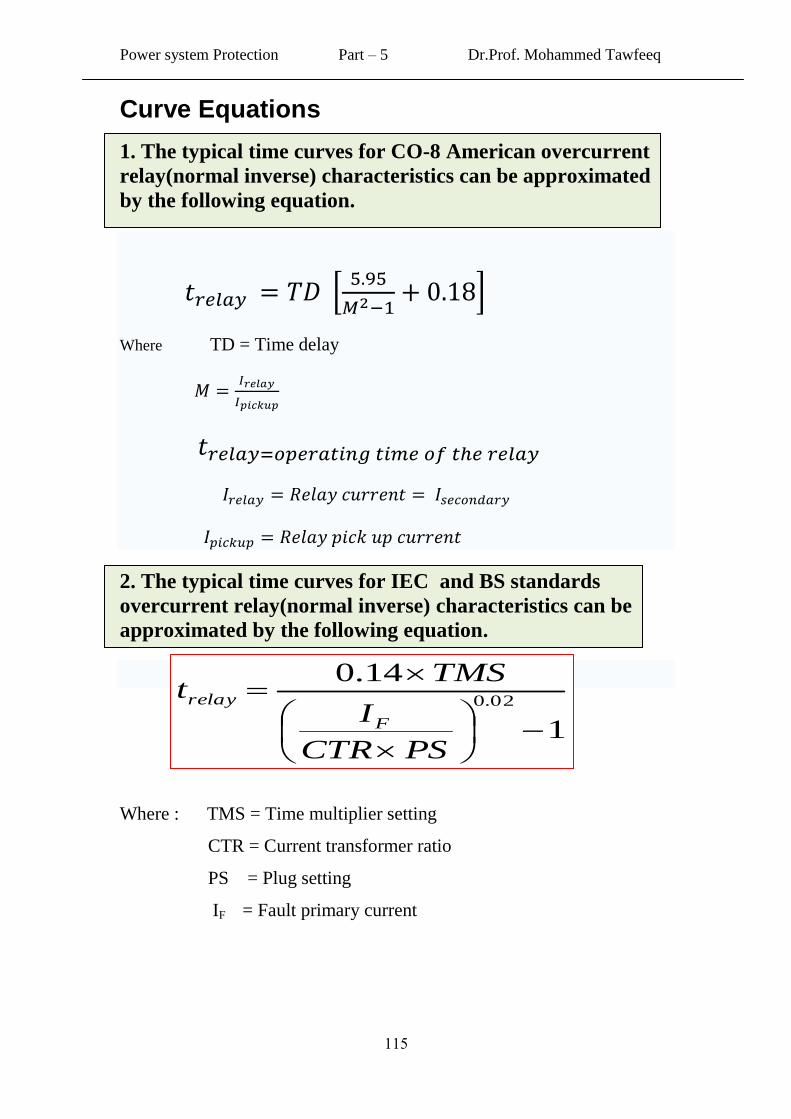
Curve Equations
1. The typical time curves for CO-8 American overcurrent
relay(normal inverse) characteristics can be approximated
by the following equation.
Where TD = Time delay
2. The typical time curves for IEC and BS standards
overcurrent relay(normal inverse) characteristics can be
approximated by the following equation.
Where : TMS = Time multiplier setting
CTR = Current transformer ratio
PS = Plug setting
IF = Fault primary current
1
14.002.0
PSCTR
I
TMSt
F
relay
Power system Protection Part – 5 Dr.Prof. Mohammed Tawfeeq
001
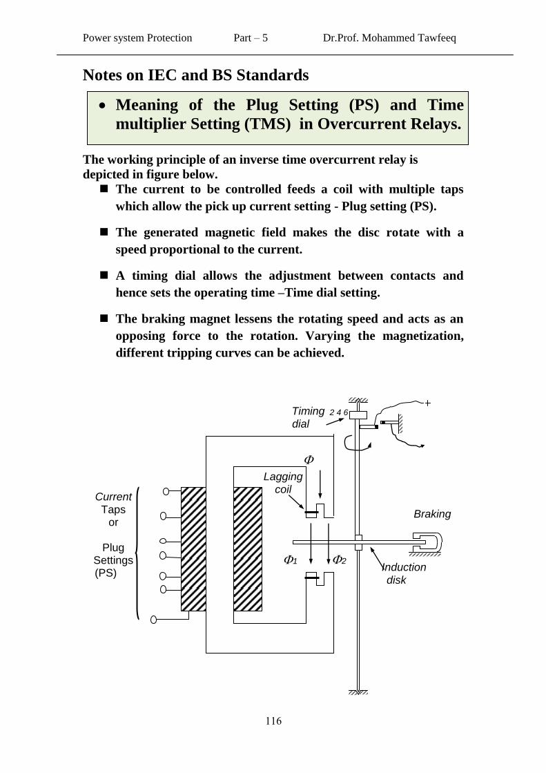
Notes on IEC and BS Standards
Meaning of the Plug Setting (PS) and Time
multiplier Setting (TMS) in Overcurrent Relays.
The working principle of an inverse time overcurrent relay is
depicted in figure below.
The current to be controlled feeds a coil with multiple taps
which allow the pick up current setting - Plug setting (PS).
The generated magnetic field makes the disc rotate with a
speed proportional to the current.
A timing dial allows the adjustment between contacts and
hence sets the operating time –Time dial setting.
The braking magnet lessens the rotating speed and acts as an
opposing force to the rotation. Varying the magnetization,
different tripping curves can be achieved.
Current Taps
or
Plug Settings (PS)
Induction disk
Lagging coil
Timing dial
Braking
2 4 6
1
2
Power system Protection Part – 5 Dr.Prof. Mohammed Tawfeeq
001
The following Table gives the equivalent names for overcurrent
relay setting in both IEC and American Standards
IEC & BS standard American Standard
Plug Setting (PS) Current Tap Setting (CTS)
Time Multiplier Setting (TMS) Time Dial Setting (TDS)
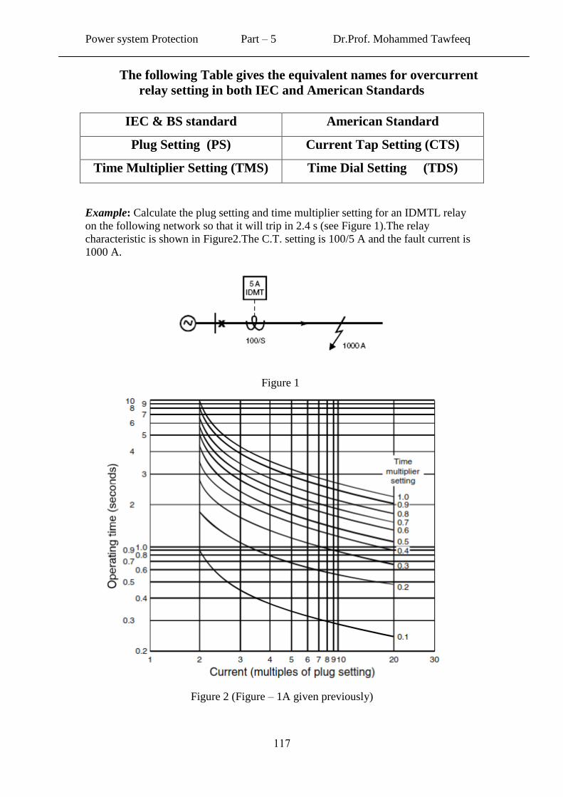
Example: Calculate the plug setting and time multiplier setting for an IDMTL relay
on the following network so that it will trip in 2.4 s (see Figure 1).The relay
characteristic is shown in Figure2.The C.T. setting is 100/5 A and the fault current is
1000 A.
Figure 1
Figure 2 (Figure – 1A given previously)
Power system Protection Part – 5 Dr.Prof. Mohammed Tawfeeq
001
Answer:
Fault current = 1000 A
CT ratio = 100/5 A
Hence expected current into relay under fault conditions,
Ir = (1000 x 5/100) = 50 A
Choose plug setting of 5 A (100%). Therefore, current into relay as a multiple of plug
setting during fault: 50 / 5 = 10
We require the relay to operate after 2.4 s as soon as this much current starts
flowing in the circuit. Referring to characteristic curves given in Figure 2
above, read time multiplier setting where 10 times plug setting current and 2.4
s cross, which is about 0.8. Accordingly, relay settings = current plug tap 5 A
(100%) and time multiplier 0.8.
Alternatively, if the current plug setting is chosen as 125% (6.25 A), the fault
current through the relay will be 50/6.25 = 8 A. The graph shows that eight
times plug setting to operate in 2.4 s, the time multiplier should be about 0.7.
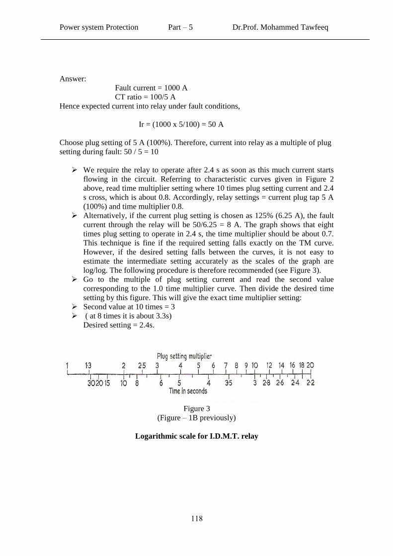
This technique is fine if the required setting falls exactly on the TM curve.
However, if the desired setting falls between the curves, it is not easy to
estimate the intermediate setting accurately as the scales of the graph are
log/log. The following procedure is therefore recommended (see Figure 3).
Go to the multiple of plug setting current and read the second value
corresponding to the 1.0 time multiplier curve. Then divide the desired time
setting by this figure. This will give the exact time multiplier setting:
Second value at 10 times = 3
( at 8 times it is about 3.3s)
Desired setting = 2.4s.
Figure 3
(Figure – 1B previously)
Logarithmic scale for I.D.M.T. relay
Power system Protection Part – 5 Dr.Prof. Mohammed Tawfeeq
009
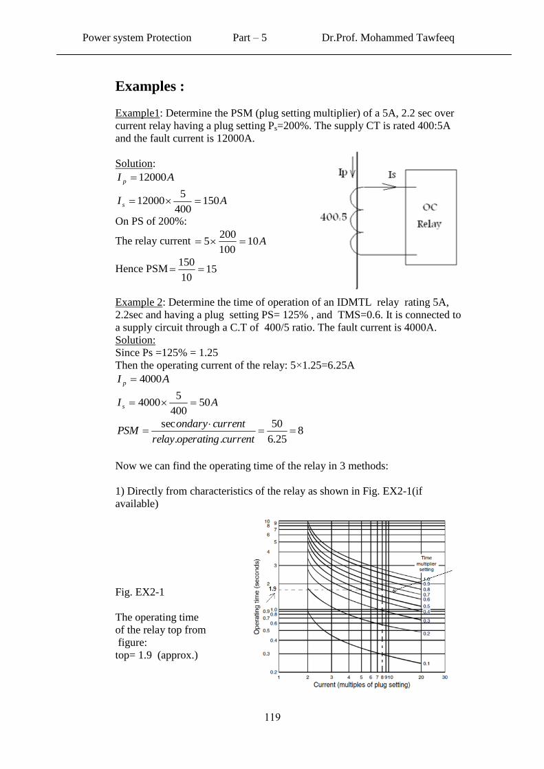
Examples :
Example1: Determine the PSM (plug setting multiplier) of a 5A, 2.2 sec over
current relay having a plug setting Ps=200%. The supply CT is rated 400:5A
and the fault current is 12000A.
Solution:
AI p 12000
AI s 150400
512000
On PS of 200%:
The relay current A10100
2005
Hence PSM 1510
150
Example 2: Determine the time of operation of an IDMTL relay rating 5A,
2.2sec and having a plug setting PS= 125% , and TMS=0.6. It is connected to
a supply circuit through a C.T of 400/5 ratio. The fault current is 4000A.
Solution:
Since Ps =125% = 1.25
Then the operating current of the relay: 5×1.25=6.25A
AI p 4000
AI s 50400
54000
825.6
50
..
sec
currentoperatingrelay
currentondaryPSM
Now we can find the operating time of the relay in 3 methods:
1) Directly from characteristics of the relay as shown in Fig. EX2-1(if
available)
Fig. EX2-1
The operating time
of the relay top from
figure:
top= 1.9 (approx.)
Power system Protection Part – 5 Dr.Prof. Mohammed Tawfeeq
011
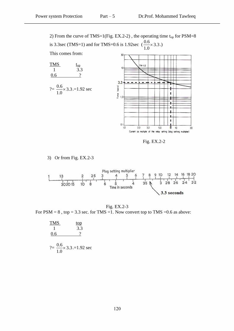
2) From the curve of TMS=1(Fig. EX.2-2) , the operating time top for PSM=8
is 3.3sec (TMS=1) and for TMS=0.6 is 1.92sec ( 3.30.1
6.0 .)
This comes from:
TMS top
1 3.3
0.6 ?
?= 3.30.1
6.0 .=1.92 sec
Fig. EX.2-2
3) Or from Fig. EX.2-3
Fig. EX.2-3
For PSM = 8 , top = 3.3 sec. for TMS =1. Now convert top to TMS =0.6 as above:
TMS top
1 3.3
0.6 ?
?= 3.30.1
6.0 .=1.92 sec
Power system Protection Part – 5 Dr.Prof. Mohammed Tawfeeq
010
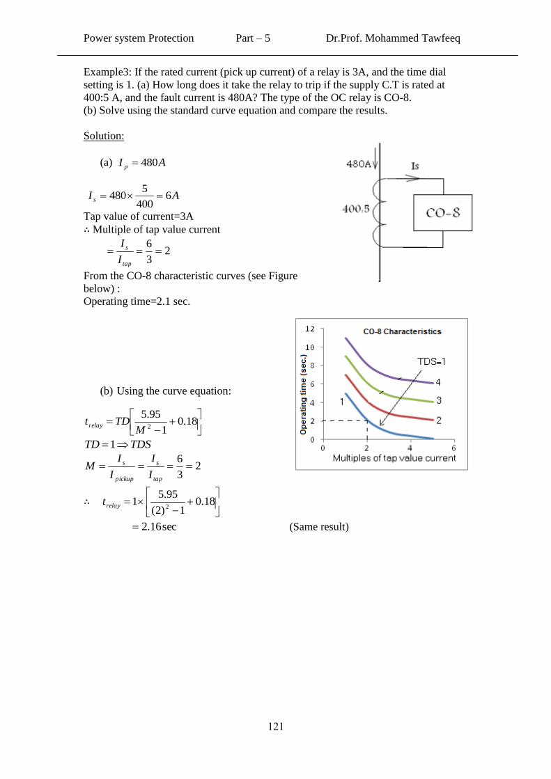
Example3: If the rated current (pick up current) of a relay is 3A, and the time dial
setting is 1. (a) How long does it take the relay to trip if the supply C.T is rated at
400:5 A, and the fault current is 480A? The type of the OC relay is CO-8.
(b) Solve using the standard curve equation and compare the results.
Solution:
(a) AI p 480
AI s 6400
5480
Tap value of current=3A
Multiple of tap value current
23
6
tap
s
I
I
From the CO-8 characteristic curves (see Figure
below) :
Operating time=2.1 sec.
(b) Using the curve equation:
18.0
1
95.52M
TDtrelay
TDSTD 1
23
6
tap
s
pickup
s
I
I
I
IM
18.0
1)2(
95.51
2relayt
sec16.2 (Same result)
Power system Protection Part – 5 Dr.Prof. Mohammed Tawfeeq
011
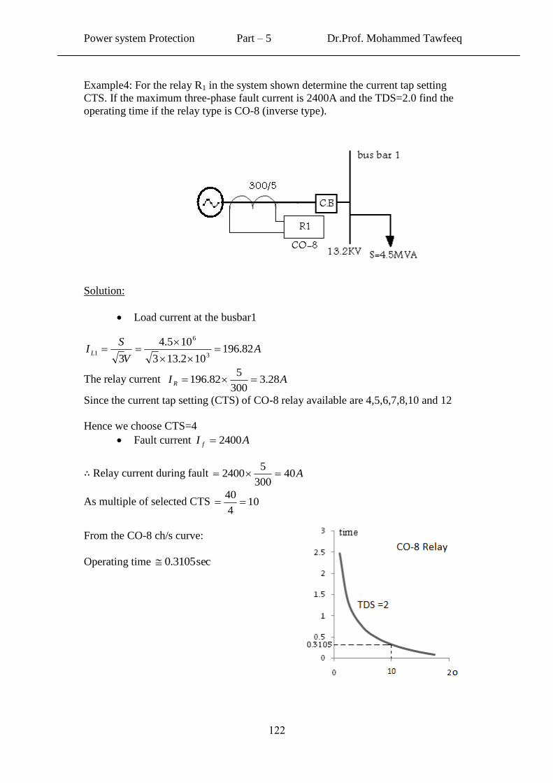
Example4: For the relay R1 in the system shown determine the current tap setting
CTS. If the maximum three-phase fault current is 2400A and the TDS=2.0 find the
operating time if the relay type is CO-8 (inverse type).
Solution:
Load current at the busbar1
AV
SI L 82.196
102.133
105.4
3 3
6
1
The relay current AI R 28.3300
582.196
Since the current tap setting (CTS) of CO-8 relay available are 4,5,6,7,8,10 and 12
Hence we choose CTS=4
Fault current AI f 2400
Relay current during fault A40300
52400
As multiple of selected CTS 104
40
From the CO-8 ch/s curve:
Operating time sec3105.0


![[PPT]Hyperemesis Gravidarum - Philadelphia University …philadelphia.edu.jo/academics/aalrazek/uploads... · Web viewHyperemesis Gravidarum Learning objective Identify Hyperemesis](https://img.pdfslide.us/doc/110x75/5af587257f8b9a190c8e7497/ppthyperemesis-gravidarum-philadelphia-university-viewhyperemesis-gravidarum.jpg)