Embed Size (px)
Citation preview
www.ijatir.org
ISSN 2348–2370
Vol.09,Issue.04,
March-2017,
Pages:0634-0640
Copyright @ 2017 IJATIR. All rights reserved.
Power Quality Improving and Harmonic Compensation by using
D-STATCOM Based Renewable Energy Sources for Induction Motor Drive J. RAMIREDDY
1, Y.V. BALARAMA KRISHNA RAO
2
1PG Scholar, Dept of EEE, Krishna Chaitanya Institute of Technology & Sciences, Prakasam(Dist), AP, India.
2Professor & HOD, Dept of EEE, Krishna Chaitanya Institute of Technology & Sciences, Prakasam(Dist), AP, India.
Abstract: For the past few year renewable energy resources,
without challenging environmental concerns has lead to significant
increase in global power generation. The quality of power can be
measured by using parameters such as voltage sag, harmonic and
power factor. To obtain the quality of power different topologies
are used. By implementing the D-STATCOM harmonics
compensation technique, the harmonics are reduced. The several
different aspects of the PV systems and the most widely addressed
technical scope is on developing various PV models integrated with
the maximum power-point tracking (MPPT) function. However, the
exploitation of wind energy is particularly challenging due to the
stochastic nature of wind. This weak interconnection of wind
generating source in the electrical network affects the power quality
and reliability. In this work, D-STATCOM voltage source inverter
(PWM-VSI) is connected between diesel generator and load which
compensates harmonics in the AC grid. Implementation of the
harmonics compensation by using D-STATCOM in the hybrid
distribution system is used to attain the voltage stability. This paper
proposes a Performance characteristics of three-phase asynchronous
motor are analyzed with renewable energy sources is connected.
Simulations have been carried out in Matlab–Simulink to study the
performance of the proposed.
Keywords: Diesel Generator, D-STATCOM, MPPT, Power
Quality, hysteresis current controller (HCC), total harmonic
distortion (THD), Wind Generating System (WGS).
I. INTRODUCTION
Harmonic disturbances and their study has been a topic of
research and today we can find a whole array of devices used
to extenuate such problems. The ever growing use of power
electronic based systems has exasperated the harmonics
problem [1]. These devices themselves require clean and
good power quality but inject unwanted harmonics into the
supply system as well as the neighboring loads. Indicate the
problems, effects and solutions for harmonics in power
systems. Different type of low voltage loads can also
introduce harmonics in the power network and adversely
affection the overall performance and operation of the power
system. In this paper, use of custom power device for
harmonic reduction is studied. Now with the scarcity of
conventional source of energy, the renewable source of
energy like solar, wind and biomass-based technologies have
shown considerable potential and are waiting to be tapped
not just for domestic use but industrial energy purposes as
well. Amongst the above mentioned sources of energy there
has been a lot of development in the technology for
harnessing energy from the wind. Wind is the motion of air
masses produced by the irregular heating of the earth’s
surface by sun [2-3]. These differences consequently create
forces that push air masses around for balancing the global
temperature or, on a much smaller scale, the temperature
between land and sea or between mountains. Wind energy is
not a constant source of energy [4].It varies continuously and
gives energy in sudden bursts. The Wind power generation
system is also play an important role in renewable power
generation, as wind is freely available there is no cost of
fuel, it does not produce greenhouse gases and other
pollutants, compared to other generation systems it does not
require huge space, as it is tall and we can use the land as
required especially in case of agriculture areas the farming
may continue. Wind turbines may available in range from
Watt to MW, so WIND power production may use vast to
business also [5-6].
According to availability of Wind speed, Wind power
generation is available from low Wind speeds to high Wind
speeds. The other advantage of Wind energy is as they are
combined operating with solar electricity which makes the
country add an advantage of steady and reliable supply of
electricity. Power quality problems are common in most of
commercial, industrial and utility networks. Natural
phenomena, such as lightning are the most frequent cause of
power quality problems. Switching phenomena resulting in
oscillatory transients in the electrical supply, for example
when capacitors are switched, also contribute substantially to
power quality disturbances. Also, the connection of high
power non-linear loads contributes to the generation of
current and voltage harmonic components. Between the
different voltage disturbances that can be produced, the most
significant and critical power quality problems are voltage
sags due to the high economical losses that can be generated.
Short term voltage drops (sags) can trip electrical drives or
more sensitive equipment, leading to costly interruptions of
production. For all these reasons, from the consumer point of
view, power quality issues will become an increasingly
important factor to consider in order to satisfy good
productivity. On the other hand, for the electrical supply
industry, the quality of power delivered will be one of the
distinguishing factors for ensuring customer loyalty in this
very competitive and deregulated market [7].
J. RAMIREDDY, Y.V. BALARAMA KRISHNA RAO
International Journal of Advanced Technology and Innovative Research
Volume. 09, IssueNo.04, March-2017, Pages: 0634-0640
To address the needs of energy consumers trying to
improve productivity through the reduction of power quality
related process stoppages and energy suppliers trying to
maximize operating profits while keeping customers
satisfied with supply quality, innovative technology provides
the key to cost-effective power quality enhancements
solutions [8]. However, with the various power quality
solutions available, the obvious question for a consumer or
utility facing a particular power quality problem is which
equipment provides the better solution [9]. This paper
focuses on the use of renewable energy sources on induction
motor drive which is by far the workhorse in industrial
applications. The advancement of power semiconductor
devices and the evolvement of several control techniques for
converter topologies have made the induction motor drives
to become the first choice for many industrial applications.
In addition to its advantages, such as speed capability,
robustness, cheapness and ease of maintenance, when used
with either vector control or direct control scheme, the
induction motor can compete with the DC motor in high-
performance applications.
II. Principle of D-STATCOM
A D-STATCOM is a controlled reactive source, which
includes a Voltage Source Converter and a DC link capacitor
connected in shunt, capable of generating and/or absorbing
reactive power. The operating principles of DSTATCOM are
based on the exact equivalence of the conventional rotating
synchronous compensator.
Fig 1.Circuit Diagram of D-STATCOM.
The AC terminals of the VSC are connected to the Point
of Common Coupling (PCC) through an inductance, which
could be a filter inductance or the leakage inductance of the
coupling transformer, as shown in Fig. 1.The DC side of the
converter is connected to a DC capacitor, which carries the
input ripple current of the converter and is the main reactive
energy storage element. This capacitor could be charged by a
battery source, or could be recharged by the converter itself.
If the output voltage of the VSC is equal to the AC terminal
voltage, no reactive power is delivered to the system. If the
output voltage is greater than the AC terminal voltage, the
DSTATCOM is in the capacitive mode of operation and vice
versa. The quantity of reactive power flow is proportional to
the difference in the two voltages. For a DSTATCOM used
for voltage regulation at the PCC, the compensation should
be such that the supply currents should lead the supply
voltages; whereas, for power factor Correction, the supply
current should be in phase with the supply voltages. The
control strategies studied in this paper are applied with a
view to studying the performance of a D-STATCOM for
power factor correction and harmonic mitigation.
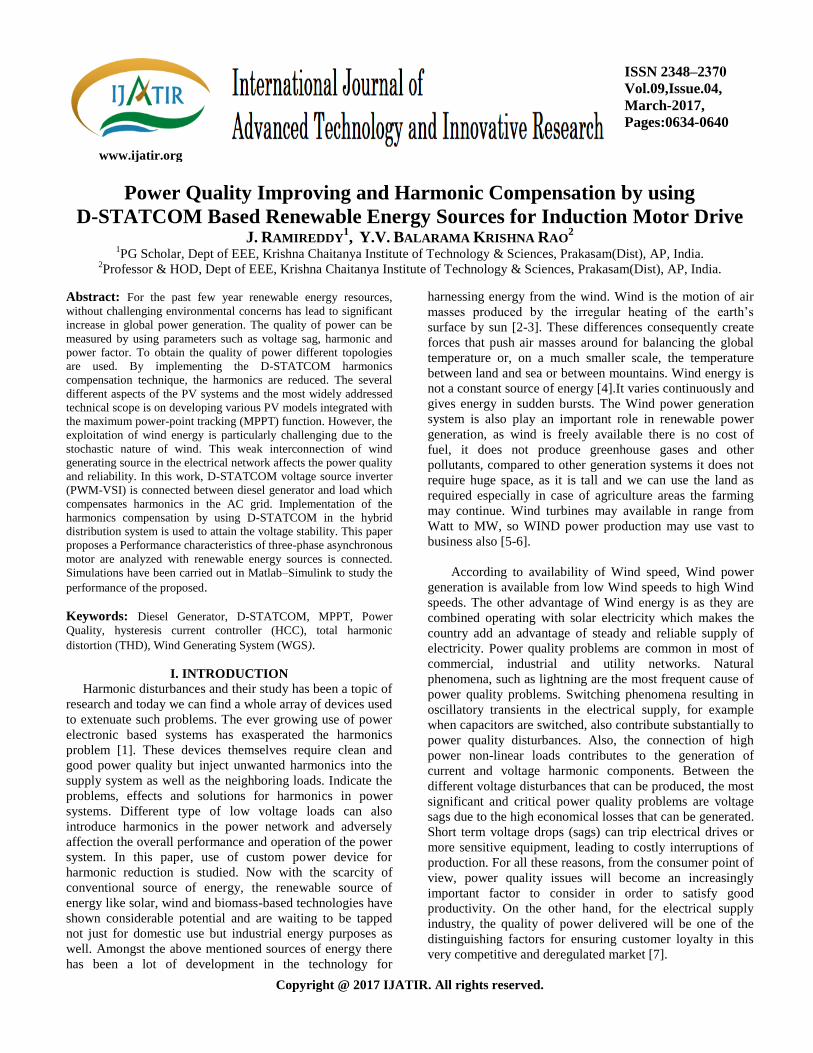
III. SYSTEM DESCRIPTION
The above system consists of a photovoltaic cell as a RES
connected to the dc-link of a grid interfacing inverter as
shown in Fig.2. The voltage source inverter (VSI) interfaces
the renewable energy source to the grid and delivers the
generated power.
Fig2. Schematic diagram of renewable based distribution
system.
A. Photovoltaic Energy Panel
PV cell is an energy conversion device, which is used to
convert the solar energy into an electrical energy and the
amount of electrical energy produced depends upon solar
irradiation and temperature.
B. Voltage Source Current Controlled Interfacing
Inverter
A voltage source current inverter is a power electronic
device which is connected in shunt with the system. The
function of this inverter is to convert the dc voltage into a
balanced three phase ac voltage. If the inverter output
voltage is greater than the existing system voltage then the
inverter acts in capacitive mode. The switching device used
in this voltage source inverter is an IGBT.
C. Control Technique for Grid Interfacing Inverter as
Shunt Active power filter
The turn ON and turn OFF instants of the inverter
switches should be such that the load and the connected RES
could be appeared as a balanced load to the system. For this
type of control, we need to monitor the output of dc link
capacitor continuously and is compared with the reference
voltage Vdc*. The difference between the reference and
actual voltages will go through a voltage regulator, whose
final output gives an active current component 1m. By
multiplying this peak value (1m) with three unit sine vectors
Power Quality Improving and Harmonic Compensation by using D-STATCOM based Renewable Energy Sources for
Induction Motor Drive
International Journal of Advanced Technology and Innovative Research
Volume. 09, IssueNo.04, March-2017, Pages: 0634-0640
(Ua, Uh and Uc) which are in phase with the three source
voltages will generate the reference current (la*, Ib
* and Ic
*).
The reference grid neutral current (In*) is set to zero being
the instantaneous sum of balanced grid currents. The
synchronizing angle (9) obtained from phase locked loop
(PLL) [I] is used to generate unity vector template as
(1)
(2)
(3)
Fig 3. Block diagram of grid interfacing inverter control.
The reference grid currents of the three phase system is
given as
(4)
(5)
(6)
The neutral current is taken as
(7)
The reference grid currents (la*, Ib
* and Ic
*) are compared
with actual grid currents (la, ,Ib and Ic) to compute the current
error as
(8)
(9)
(10)
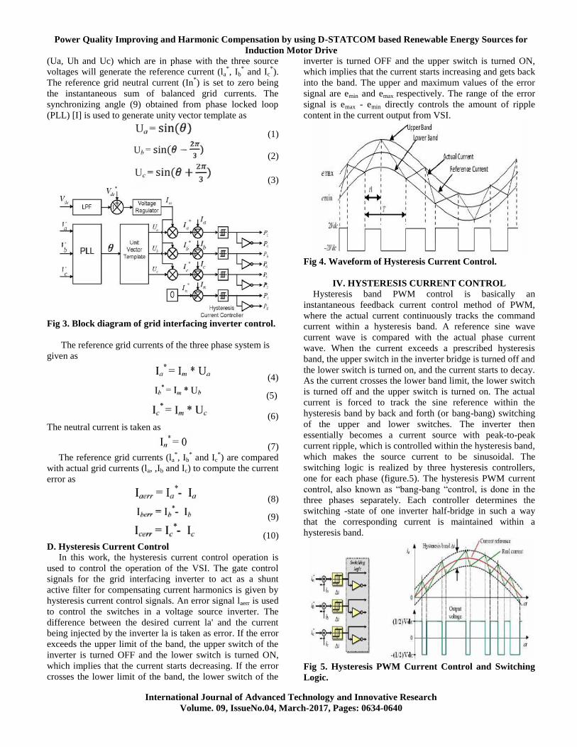
D. Hysteresis Current Control
In this work, the hysteresis current control operation is
used to control the operation of the VSI. The gate control
signals for the grid interfacing inverter to act as a shunt
active filter for compensating current harmonics is given by
hysteresis current control signals. An error signal laerr is used
to control the switches in a voltage source inverter. The
difference between the desired current la' and the current
being injected by the inverter la is taken as error. If the error
exceeds the upper limit of the band, the upper switch of the
inverter is turned OFF and the lower switch is turned ON,
which implies that the current starts decreasing. If the error
crosses the lower limit of the band, the lower switch of the
inverter is turned OFF and the upper switch is turned ON,
which implies that the current starts increasing and gets back
into the band. The upper and maximum values of the error
signal are emin and emax respectively. The range of the error
signal is emax - emin directly controls the amount of ripple
content in the current output from VSI.
Fig 4. Waveform of Hysteresis Current Control.
IV. HYSTERESIS CURRENT CONTROL Hysteresis band PWM control is basically an
instantaneous feedback current control method of PWM,
where the actual current continuously tracks the command
current within a hysteresis band. A reference sine wave
current wave is compared with the actual phase current
wave. When the current exceeds a prescribed hysteresis
band, the upper switch in the inverter bridge is turned off and
the lower switch is turned on, and the current starts to decay.
As the current crosses the lower band limit, the lower switch
is turned off and the upper switch is turned on. The actual
current is forced to track the sine reference within the
hysteresis band by back and forth (or bang-bang) switching
of the upper and lower switches. The inverter then
essentially becomes a current source with peak-to-peak
current ripple, which is controlled within the hysteresis band,
which makes the source current to be sinusoidal. The
switching logic is realized by three hysteresis controllers,
one for each phase (figure.5). The hysteresis PWM current
control, also known as “bang-bang “control, is done in the
three phases separately. Each controller determines the
switching -state of one inverter half-bridge in such a way
that the corresponding current is maintained within a
hysteresis band.
Fig 5. Hysteresis PWM Current Control and Switching
Logic.
J. RAMIREDDY, Y.V. BALARAMA KRISHNA RAO
International Journal of Advanced Technology and Innovative Research
Volume. 09, IssueNo.04, March-2017, Pages: 0634-0640
To increase a phase current, the affiliated phase to neutral
voltage is equal to the half dc bus voltage until the upper
band-range is reached. Then, the negative dc bus voltage -
½Udc applied as long as the lower limit is reached &c. More
complicated hysteresis PWM current control techniques also
exist in practice, e.g. adaptive hysteresis current vector
control is based on controlling the current phasor in a α/β -
reference frame. These modified techniques take care
especially for the interaction of the three phases. Obviously,
the dynamic performance of such an approach is excellent
since the maximum voltage is applied until the current error
is within predetermined boundaries (bang-bang control). Due
to the elimination of an additional current controller, the
motor parameter dependence is vastly reduced. However,
there are some inherent drawbacks.
1. No fixed PWM frequency: The hysteresis controller
generates involuntary lower sub harmonics.
2. The current error is not strictly limited. The signal may
leave the hysteresis band caused by the voltage of the
other two phases.
3. Usually, there is no interaction between the three
phases: No strategy to generate zero-voltage phasors.
4. Increased switching frequency (losses) especially at
lower modulation or motor speed.
5. Phase lag of the fundamental current (increasing with
the frequency).
Hysteresis current control is used for operation at higher
switching frequency, as this compensates for their inferior
quality of modulation. The switching losses restrict its
application to lower power levels. Due to the independence
of motor parameters, hysteresis current control is often
preferred for stepper motors and other variable-reluctance
motors. A carrier-based modulation technique, as described
in the next subsection, eliminates the basic shortcomings
of the hysteresis PWM controller. However, when being
compared to the hysteresis PWM, an additional current
control loop, calculating the reference voltages, is required
when subsequent modulation schemes are applied to high-
performance motion control systems.
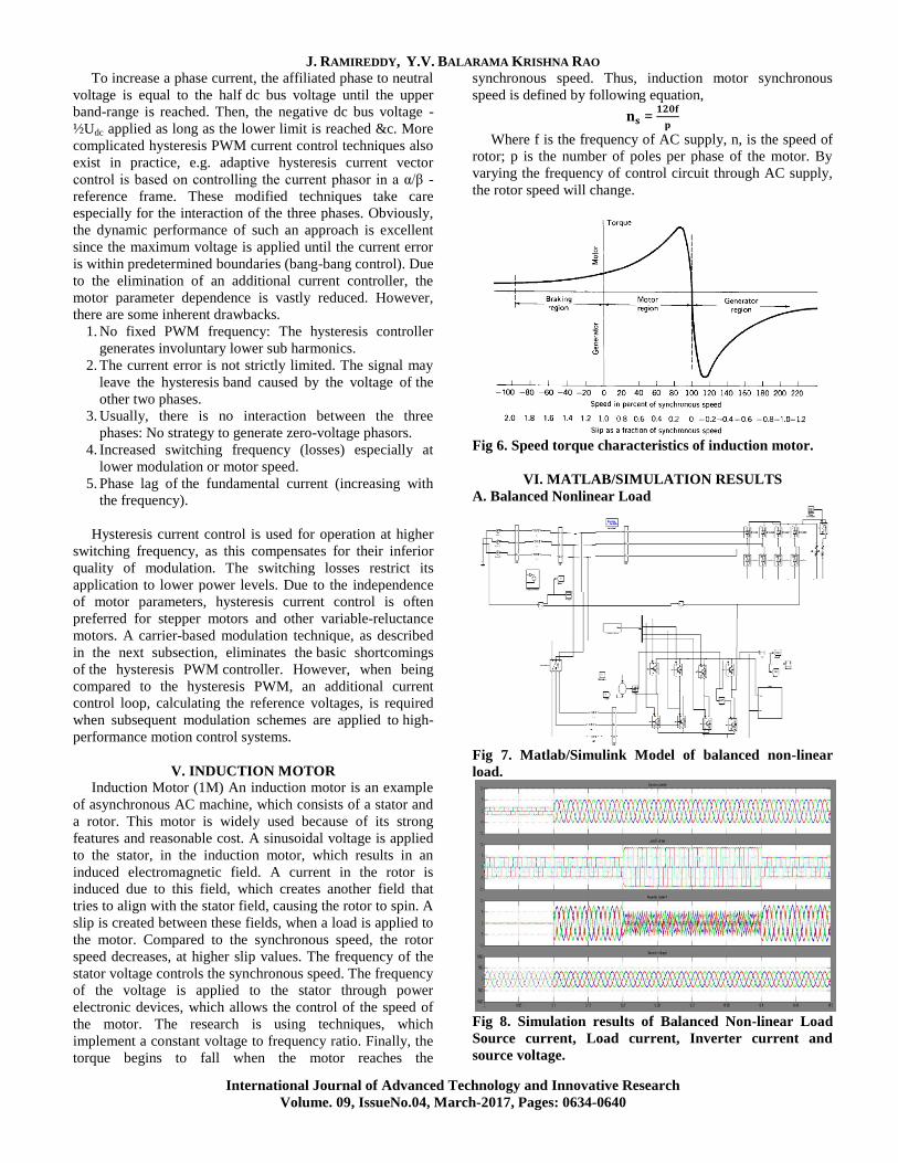
V. INDUCTION MOTOR
Induction Motor (1M) An induction motor is an example
of asynchronous AC machine, which consists of a stator and
a rotor. This motor is widely used because of its strong
features and reasonable cost. A sinusoidal voltage is applied
to the stator, in the induction motor, which results in an
induced electromagnetic field. A current in the rotor is
induced due to this field, which creates another field that
tries to align with the stator field, causing the rotor to spin. A
slip is created between these fields, when a load is applied to
the motor. Compared to the synchronous speed, the rotor
speed decreases, at higher slip values. The frequency of the
stator voltage controls the synchronous speed. The frequency
of the voltage is applied to the stator through power
electronic devices, which allows the control of the speed of
the motor. The research is using techniques, which
implement a constant voltage to frequency ratio. Finally, the
torque begins to fall when the motor reaches the
synchronous speed. Thus, induction motor synchronous
speed is defined by following equation,
=
Where f is the frequency of AC supply, n, is the speed of
rotor; p is the number of poles per phase of the motor. By
varying the frequency of control circuit through AC supply,
the rotor speed will change.
Fig 6. Speed torque characteristics of induction motor.
VI. MATLAB/SIMULATION RESULTS
A. Balanced Nonlinear Load
Fig 7. Matlab/Simulink Model of balanced non-linear
load.
Fig 8. Simulation results of Balanced Non-linear Load
Source current, Load current, Inverter current and
source voltage.
Power Quality Improving and Harmonic Compensation by using D-STATCOM based Renewable Energy Sources for
Induction Motor Drive
International Journal of Advanced Technology and Innovative Research
Volume. 09, IssueNo.04, March-2017, Pages: 0634-0640
Fig 9. Source voltage and current.
Fig 10. THD of source current before compensation.
The source current of balanced Non-linear load before
compensation is 30.15%.
Fig 11. THD of source current after compensation.
The source current of balanced Non-linear load after
compensation is 1.90%.
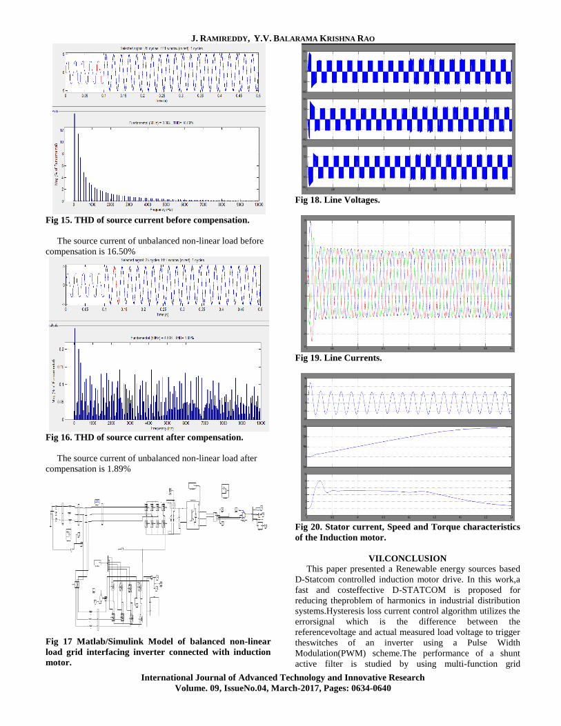
B. Unbalanced Non-linear Load
Fig 12.Matlab/Simulink Model of unbalanced non-linear
load.
Fig 13. Simulation results of unbalanced Non-linear Load
Source current, Load current, Inverter current and
source voltage.
Fig 14.source voltage and current.
J. RAMIREDDY, Y.V. BALARAMA KRISHNA RAO
International Journal of Advanced Technology and Innovative Research
Volume. 09, IssueNo.04, March-2017, Pages: 0634-0640
Fig 15. THD of source current before compensation.
The source current of unbalanced non-linear load before
compensation is 16.50%
Fig 16. THD of source current after compensation.
The source current of unbalanced non-linear load after
compensation is 1.89%
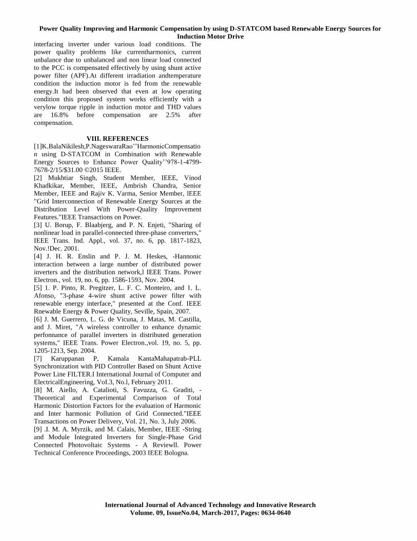
Fig 17 Matlab/Simulink Model of balanced non-linear
load grid interfacing inverter connected with induction
motor.
Fig 18. Line Voltages.
Fig 19. Line Currents.
Fig 20. Stator current, Speed and Torque characteristics
of the Induction motor.
VII.CONCLUSION
This paper presented a Renewable energy sources based
D-Statcom controlled induction motor drive. In this work,a
fast and costeffective D-STATCOM is proposed for
reducing theproblem of harmonics in industrial distribution
systems.Hysteresis loss current control algorithm utilizes the
errorsignal which is the difference between the
referencevoltage and actual measured load voltage to trigger
theswitches of an inverter using a Pulse Width
Modulation(PWM) scheme.The performance of a shunt
active filter is studied by using multi-function grid
Power Quality Improving and Harmonic Compensation by using D-STATCOM based Renewable Energy Sources for
Induction Motor Drive
International Journal of Advanced Technology and Innovative Research
Volume. 09, IssueNo.04, March-2017, Pages: 0634-0640
interfacing inverter under various load conditions. The
power quality problems like currentharmonics, current
unbalance due to unbalanced and non linear load connected
to the PCC is compensated effectively by using shunt active
power filter (APF).At different irradiation andtemperature
condition the induction motor is fed from the renewable
energy.It had been observed that even at low operating
condition this proposed system works efficiently with a
verylow torque ripple in induction motor and THD values
are 16.8% before compensation are 2.5% after
compensation.
VIII. REFERENCES
[1]K.BalaNikilesh,P.NageswaraRao’’HarmonicCompensatio
n using D-STATCOM in Combination with Renewable
Energy Sources to Enhance Power Quality’’978-1-4799-
7678-2/15/$31.00 ©2015 IEEE.
[2] Mukhtiar Singh, Student Member, IEEE, Vinod
Khadkikar, Member, IEEE, Ambrish Chandra, Senior
Member, IEEE and Rajiv K. Varma, Senior Member, lEEE
"Grid Interconnection of Renewable Energy Sources at the
Distribution Level With Power-Quality Improvement
Features."IEEE Transactions on Power.
[3] U. Borup, F. Blaabjerg, and P. N. Enjeti, "Sharing of
nonlinear load in parallel-connected three-phase converters,"
IEEE Trans. Ind. Appl., vol. 37, no. 6, pp. 1817-1823,
Nov.!Dec. 2001.
[4] J. H. R. Enslin and P. J. M. Heskes, -Hannonic
interaction between a large number of distributed power
inverters and the distribution network,l IEEE Trans. Power
Electron., vol. 19, no. 6, pp. 1586-1593, Nov. 2004.
[5] 1. P. Pinto, R. Pregitzer, L. F. C. Monteiro, and 1. L.
Afonso, "3-phase 4-wire shunt active power filter with
renewable energy interface," presented at the Conf. IEEE
Rnewable Energy & Power Quality, Seville, Spain, 2007.
[6] J. M. Guerrero, L. G. de Vicuna, J. Matas, M. Castilla,
and J. Miret, "A wireless controller to enhance dynamic
perfonnance of parallel inverters in distributed generation
systems," IEEE Trans. Power Electron.,vol. 19, no. 5, pp.
1205-1213, Sep. 2004.
[7] Karuppanan P, Kamala KantaMahapatrab-PLL
Synchronization with PID Controller Based on Shunt Active
Power Line FILTER.I International Journal of Computer and
ElectricalEngineering, VoI.3, No.l, February 2011.
[8] M. Aiello, A. Catalioti, S. Favuzza, G. Graditi, -
Theoretical and Experimental Comparison of Total
Harmonic Distortion Factors for the evaluation of Harmonic
and Inter harmonic Pollution of Grid Connected."IEEE
Transactions on Power Delivery, Vol. 21, No. 3, July 2006.
[9] .I. M. A. Myrzik, and M. Calais, Member, IEEE -String
and Module Integrated Inverters for Single-Phase Grid
Connected Photovoltaic Systems - A Reviewll. Power
Technical Conference Proceedings, 2003 IEEE Bologna.