Embed Size (px)
Citation preview
1
3-Phase Shunt Active Filter for Harmonic compensation
Unnikrishnan A.K., Aby Joseph and Subhash Joshi T.G.,
CDAC Trivandrum
2
The Case under studyPeekay Steels, CalicutInduction FurnaceAuxiliary Load
Furnace Load cycleLining / SinteringHeating
Current WaveformsLining / SinteringHeating
Overview of the Presentation
IEEE Standard 519PQ SolutionsImprovements in Current waveforms
3
Site Study
4
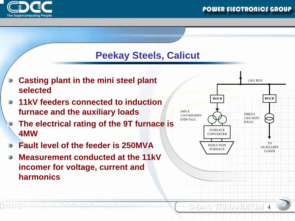
Casting plant in the mini steel plant selected11kV feeders connected to induction furnace and the auxiliary loadsThe electrical rating of the 9T furnace is 4MWFault level of the feeder is 250MVAMeasurement conducted at the 11kV incomer for voltage, current and harmonics
Peekay Steels, Calicut
FURNACECONVERTER
INDUCTIONFURNACE
11kV BUS
5MVA 11kV/850-850VD/D6-Υn11
BOCB
TOAUXILIARY
LOADS
500kVA11kV/433VDYn11
BOCB
5
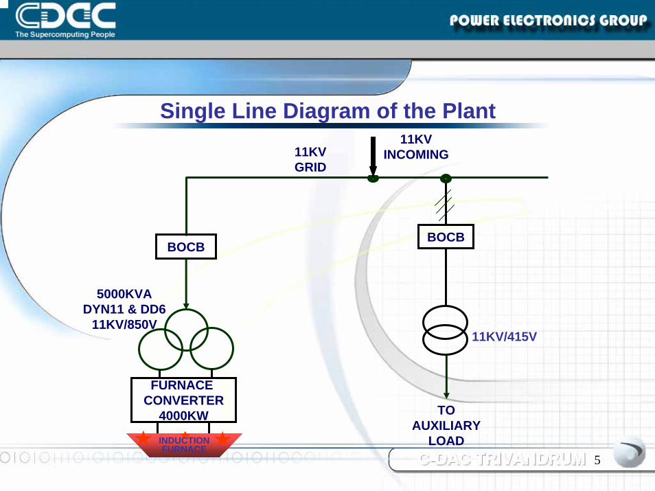
BOCB
11KV GRID
11KV INCOMING
TO AUXILIARY
LOAD
FURNACE CONVERTER
4000KW
5000KVA DYN11 & DD6
11KV/850V
BOCB
11KV/415V
INDUCTION FURNACE
Single Line Diagram of the Plant
6
Input is through two 6P converters fed by a D/Y/D transformerThe furnace can operate with one 6P converter or both the converters to form 12PThe converter panel has AC capacitor banks to improve the converter power factorThe capacity of the furnace is 9 Ton, 4MWThe furnace has two crucibles which are used alternatively
The 4MW Induction Furnace
7
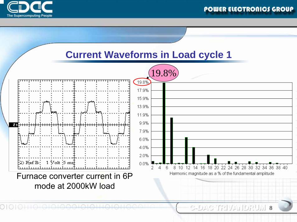
Lining / SinteringForming the Refractory LiningHeats slowly starting with power level as low as 200kWStarts with single converter (6P) and continues till 2000kWPower factor fluctuates between 0.39 and 0.95Dominant Current harmonics are 5th and 7th
Furnace Load Cycle 1
8
Furnace converter current in 6P mode at 2000kW load
Current Waveforms in Load cycle 1
19.8%
9
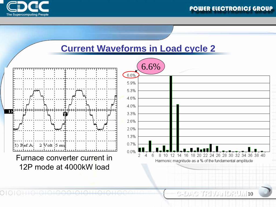
HeatingSecond converter switched ON from 2000kW onwards and configuration becomes 12PMelting of scrap metalPower level fluctuates and reaches 4000kWPower factor is varying between 0.60 and 0.95Current harmonics exceeds 12% with 11th and 13th dominating
Furnace Load Cycle 2
10
Furnace converter current in 12P mode at 4000kW load
Current Waveforms in Load cycle 2
6.6%
11
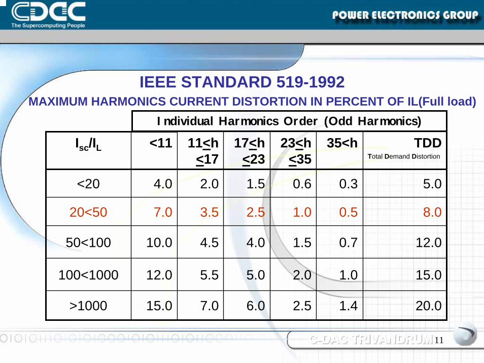
MAXIMUM HARMONICS CURRENT DISTORTION IN PERCENT OF IL(Full load)Individual Harmonics Order (Odd Harmonics)
IEEE STANDARD 519-1992
Isc/IL <11 11<h<17
17<h<23
23<h<35
35<h TDDTotal Demand Distortion
<20 4.0 2.0 1.5 0.6 0.3 5.0
20<50 7.0 3.5 2.5 1.0 0.5 8.0
50<100 10.0 4.5 4.0 1.5 0.7 12.0
100<1000 12.0 5.5 5.0 2.0 1.0 15.0
>1000 15.0 7.0 6.0 2.5 1.4 20.0
12
Frequent failure of CTs and PTs in substationHeating of substation transformerFailure of fans and lamps in the plant
PQ Issues at Site
13
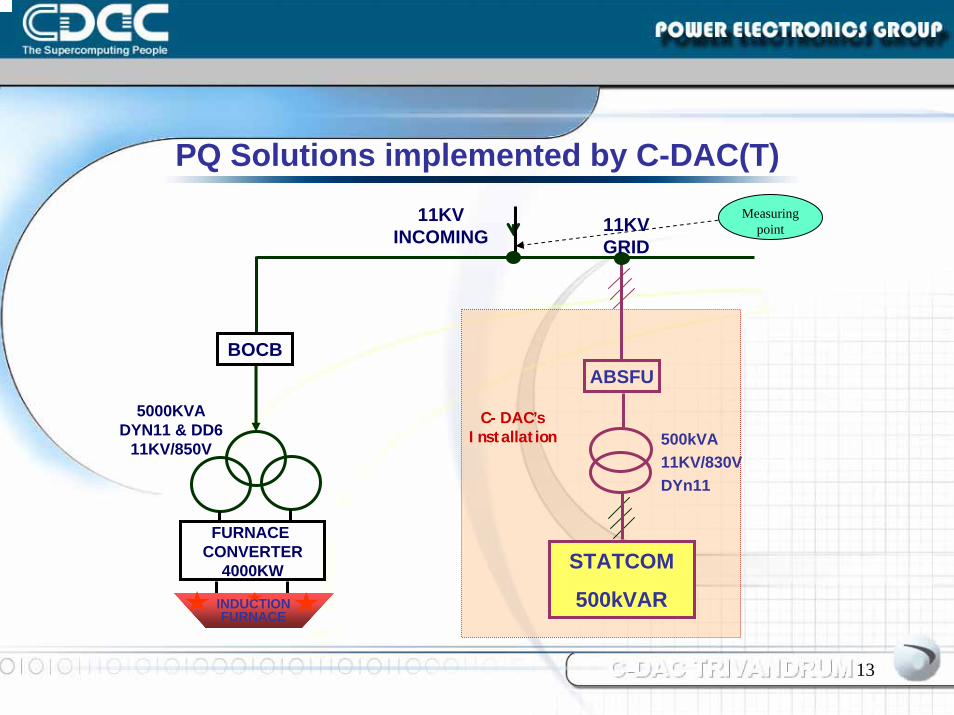
PQ Solutions implemented by C-DAC(T)
11KV GRID
11KV INCOMING
FURNACE CONVERTER
4000KW
5000KVA DYN11 & DD6
11KV/850V
STATCOM
500kVAR
C-DAC’s Installation 500kVA
11KV/830VDYn11
ABSFU
Measuring point
INDUCTION FURNACE
BOCB
14
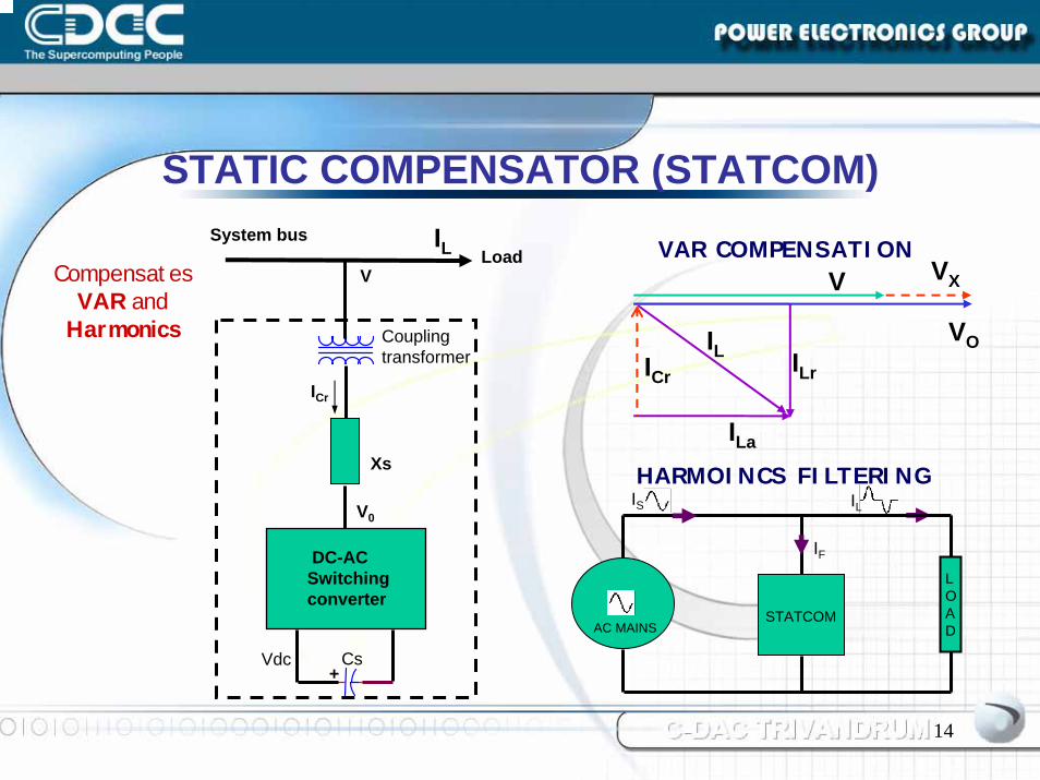
STATIC COMPENSATOR (STATCOM)
LoadSystem bus
V
Coupling transformer
ICr
Xs
V0
DC-ACSwitchingconverter
+CsVdc
ILV
ILr
ILa
ICr
VO
VX
IL
VAR COMPENSATION
STATCOM
LOADAC MAINS
ILIS
IF
HARMOINCS FILTERING
Compensates VAR and
Harmonics
15
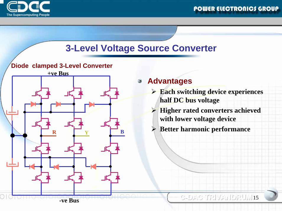
AdvantagesEach switching device experiences half DC bus voltageHigher rated converters achieved with lower voltage device Better harmonic performance
Diode clamped 3-Level Converter
YR
+ve Bus
3-Level Voltage Source Converter
B
-ve Bus
16
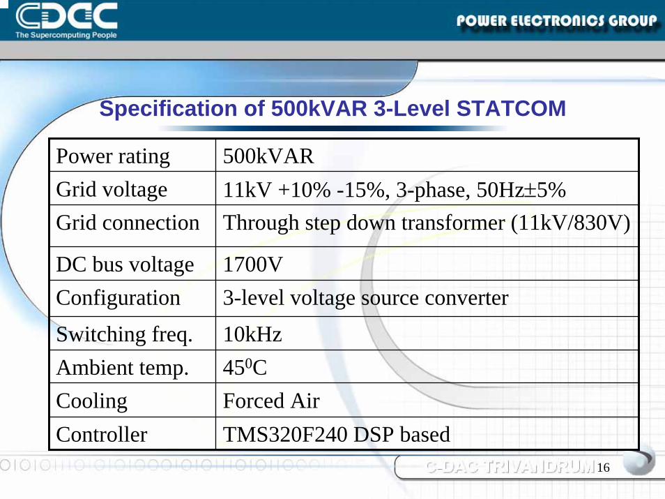
Power rating 500kVARGrid voltage 11kV +10% -15%, 3-phase, 50Hz±5%Grid connection Through step down transformer (11kV/830V)
DC bus voltage 1700VConfiguration 3-level voltage source converter
Switching freq. 10kHzAmbient temp. 450CCooling Forced AirController TMS320F240 DSP based
Specification of 500kVAR 3-Level STATCOM
17
Hardware Configuration
18
Converter Stack
IGBTsCapacitor bankOver temperature protectionGate driver PCBInter connections with sandwich busbars
19
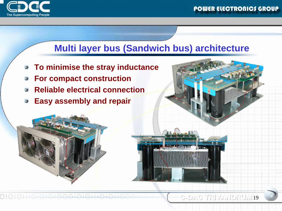
Multi layer bus (Sandwich bus) architecture
To minimise the stray inductanceFor compact constructionReliable electrical connectionEasy assembly and repair
20
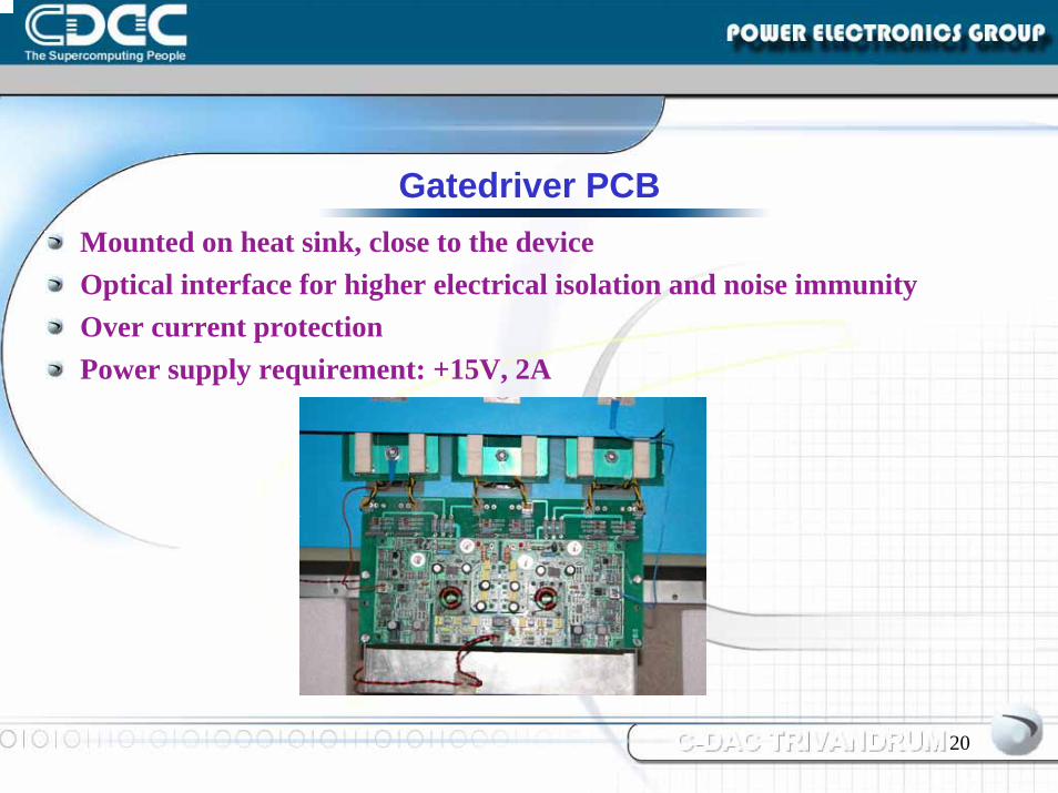
Gatedriver PCBMounted on heat sink, close to the deviceOptical interface for higher electrical isolation and noise immunityOver current protectionPower supply requirement: +15V, 2A
21
Control Strategy
22
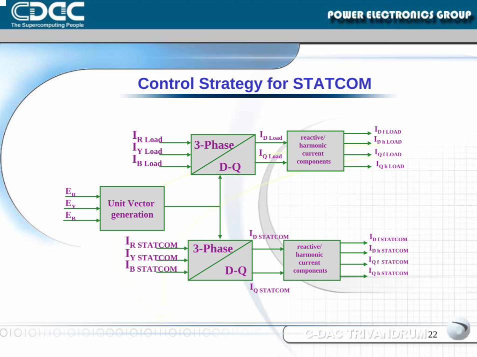
Control Strategy for STATCOM
Unit Vector generation
EREYEB
3-Phase
D-Q
IR Load
IB Load
IY LoadID h LOAD
IQ f LOAD
reactive/ harmonic current
components
3-Phase
D-Q
IR STATCOMIY STATCOMIB STATCOM
reactive/ harmonic current
components
ID STATCOM
ID f LOAD
ID f STATCOM
IQ h STATCOM
IQ f STATCOM
ID h STATCOM
IQ STATCOM
ID Load
IQ LoadIQ h LOAD
23
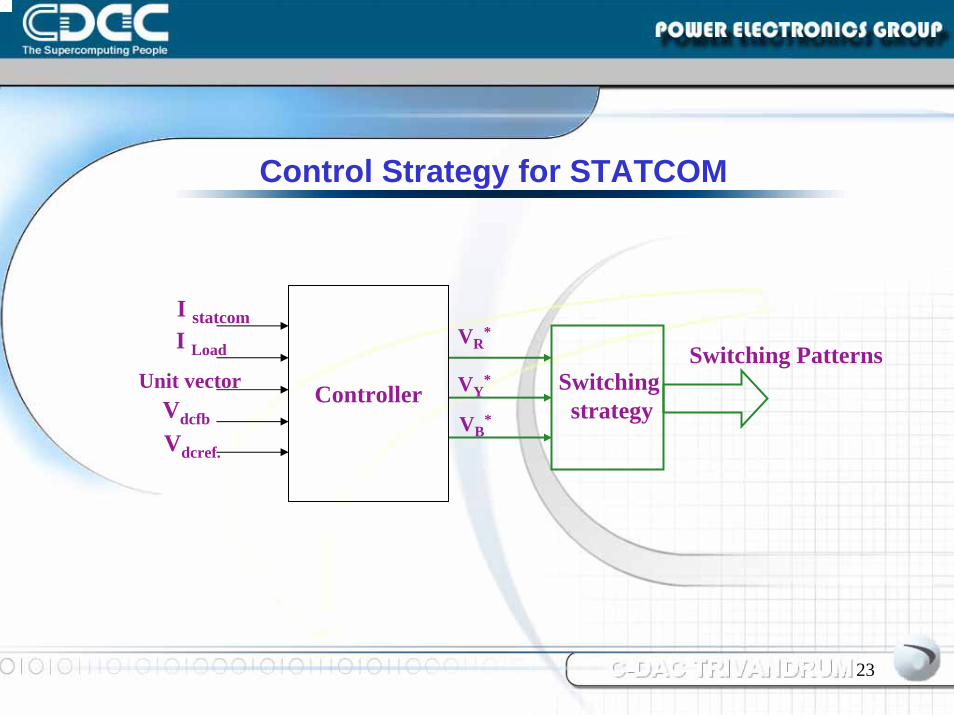
Control Strategy for STATCOM
VR*
VY*
VB*
Switching strategy
Switching PatternsController
I statcom
Unit vector
I Load
Vdcfb
Vdcref.
24
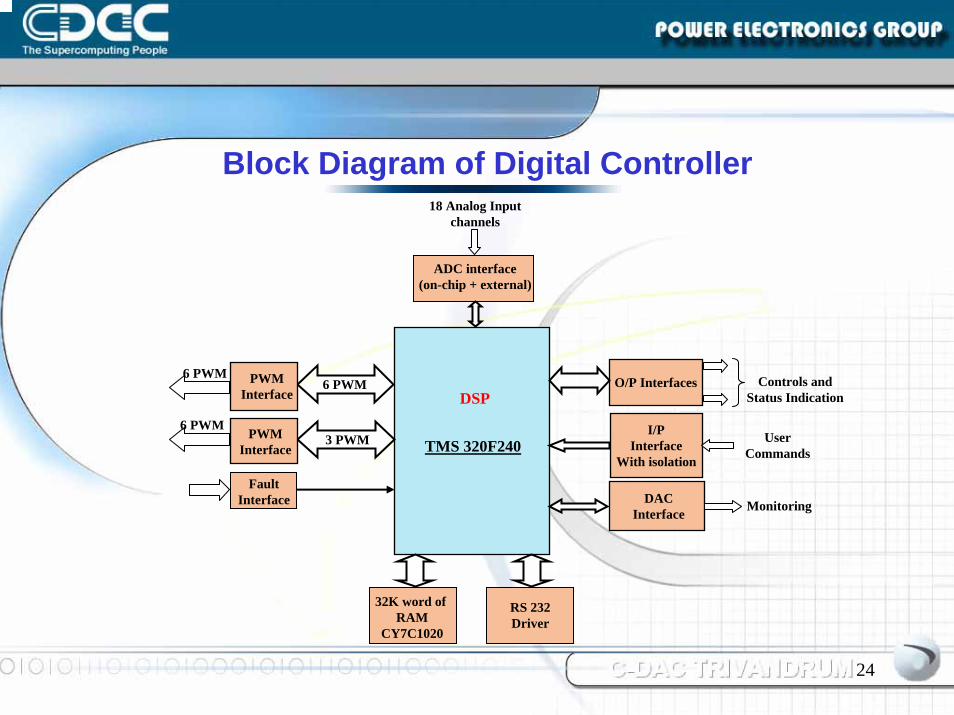
Block Diagram of Digital Controller18 Analog Input
channels
32K word of RAM
CY7C1020
TMS 320F240
6 PWM
3 PWM
DSP
ADC interface(on-chip + external)
PWM Interface
PWM Interface
6 PWM
6 PWM
DACInterface
O/P Interfaces
I/PInterface
With isolation
Monitoring
Fault Interface
User Commands
Controls and Status Indication
RS 232Driver
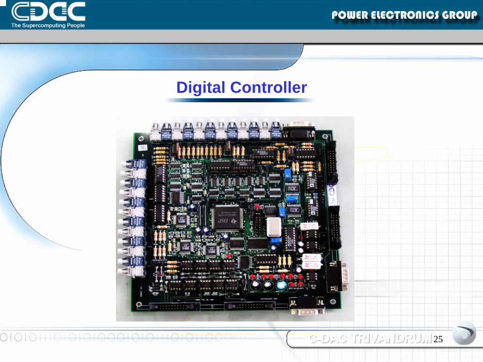
25
Digital Controller
26
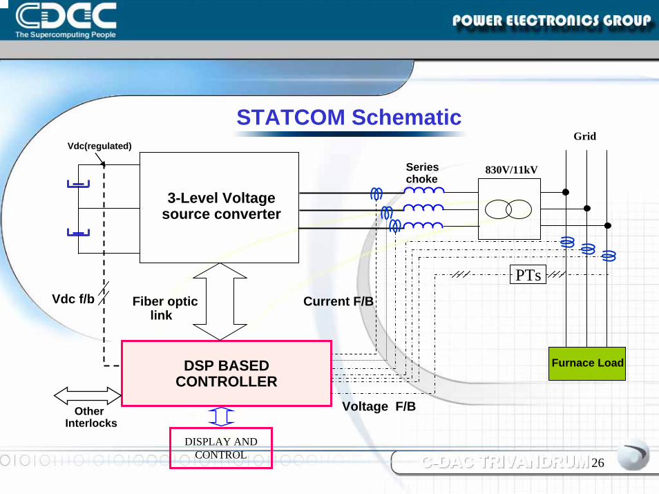
STATCOM SchematicVdc(regulated)
Grid
DSP BASEDCONTROLLER
Current F/BFiber opticlink
DISPLAY ANDCONTROL
OtherInterlocks
Series choke
3-Level Voltage source converter
Furnace Load
Voltage F/B
PTs
830V/11kV
Vdc f/b
27
Test Results
28CCC---DAC TRIVANDRUMDAC TRIVANDRUMDAC TRIVANDRUM
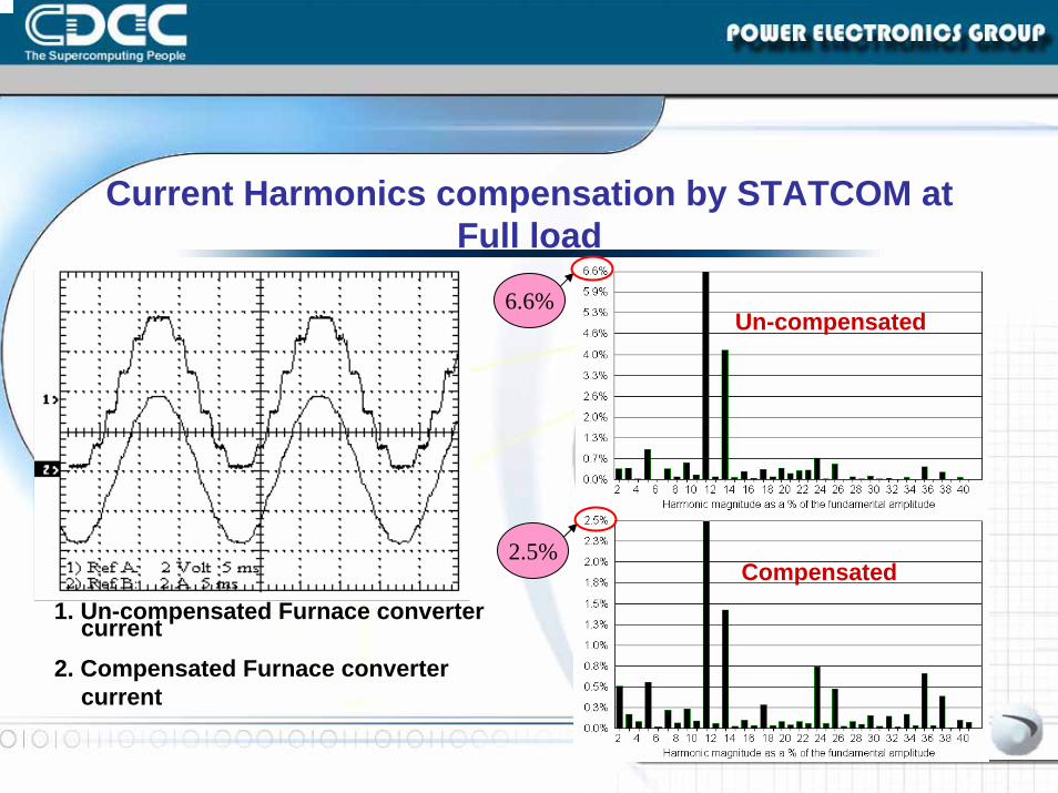
Current Harmonics compensation by STATCOM at Full load
Un-compensated
Compensated
6.6%
2.5%
1. Un-compensated Furnace converter current
2. Compensated Furnace converter current
29
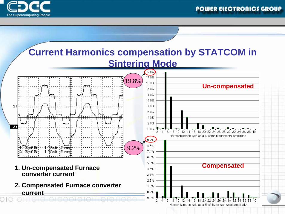
Un-compensated
CCC---DAC TRIVANDRUMDAC TRIVANDRUMDAC TRIVANDRUM
Compensated
Current Harmonics compensation by STATCOM in Sintering Mode
19.8%
9.2%
1. Un-compensated Furnace converter current
2. Compensated Furnace converter current
30
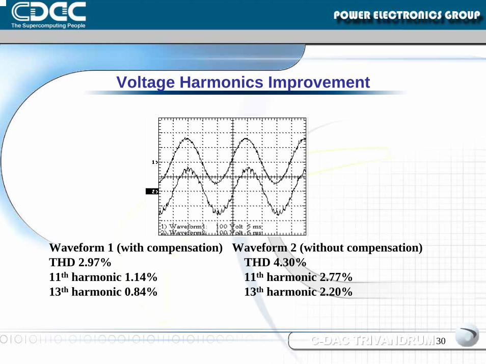
Voltage Harmonics Improvement
Waveform 1 (with compensation) Waveform 2 (without compensation)THD 2.97% THD 4.30%11th harmonic 1.14% 11th harmonic 2.77%13th harmonic 0.84% 13th harmonic 2.20%
31
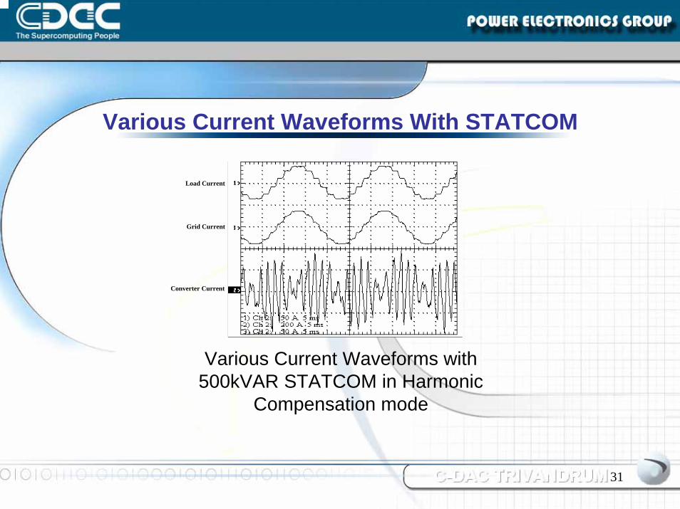
Load Current
Grid Current
Converter Current
Various Current Waveforms With STATCOM
Various Current Waveforms with 500kVAR STATCOM in Harmonic
Compensation mode
32
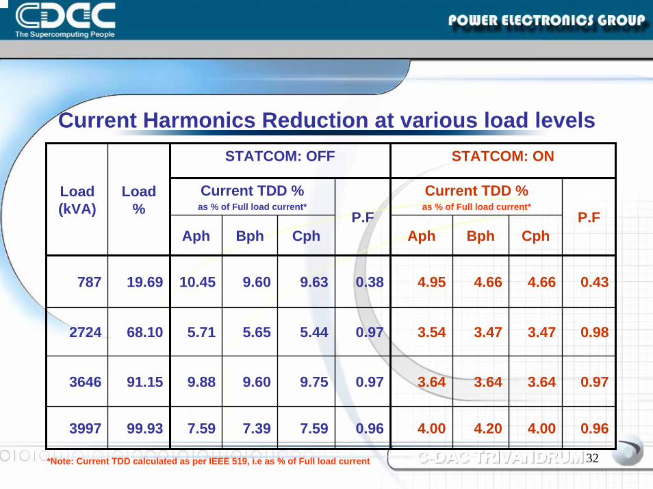
STATCOM: OFF STATCOM: ON
Current TDD %as % of Full load current*
Current TDD %as % of Full load current*
P.F P.F
0.43
0.98
0.97
0.96
Aph Bph Cph Aph Bph Cph
0.38
0.97
0.97
0.96
Load (kVA)
Load %
787 19.69 10.45 9.60 9.63 4.95 4.66 4.66
2724 68.10 5.71 5.65 5.44 3.54 3.47 3.47
3646 91.15 9.88 9.60 9.75 3.64 3.64 3.64
3997 99.93 7.59 7.39 7.59 4.00 4.20 4.00
Current Harmonics Reduction at various load levels
*Note: Current TDD calculated as per IEEE 519, i.e as % of Full load current
33
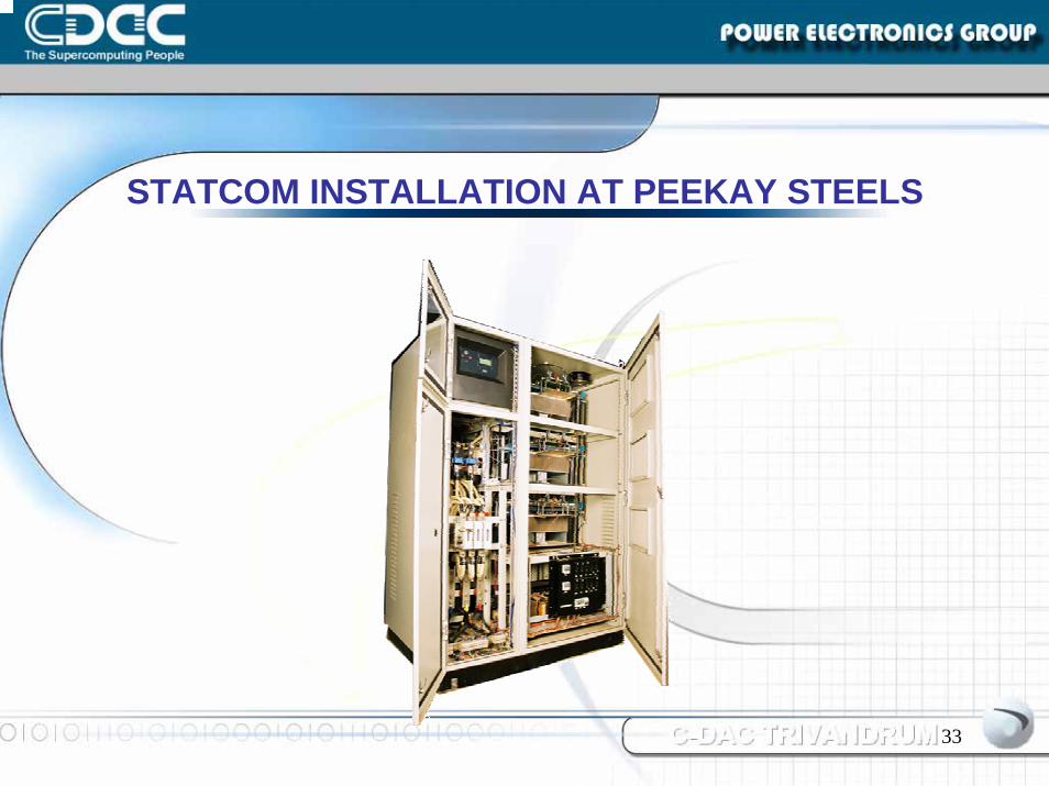
STATCOM INSTALLATION AT PEEKAY STEELS
34
Thank youThank you