Embed Size (px)
Citation preview

KRISHAK BHARTI COOPERATIVE LIMITED REVAMP OF CAPTIVE POWER PLANT - HAZIRA
(POWER PLANT DESIGN BASIS)
SECTION B-1.1
Page 1 of 16
SECTION B – 1.1
POWER PLANT DESIGN BASIS
KRISHAK BHARTI COOPERATIVE LIMITED REVAMP OF CAPTIVE POWER PLANT - HAZIRA
(POWER PLANT DESIGN BASIS)
SECTION B-1.1
Page 2 of 16
CONTENTS
S. No. DESCRIPTION PAGE
1. INTRODUCTION 3
2. SITE CONDITION 3
3. DESIGN DATA 4
4. CAPTIVE POWER PLANT 4
5 DESIGN CONSIDERATIONS FOR CPP 10
6 SPECIAL DESIGN REQUIREMENTS FOR MAJOR
EQUIPMENTS 12
7. REDUNDANCY PHILOSOPHY 15
8. BUILDINGS / SHED 15
9. ANNEXURE 15
KRISHAK BHARTI COOPERATIVE LIMITED REVAMP OF CAPTIVE POWER PLANT - HAZIRA
(POWER PLANT DESIGN BASIS)
SECTION B-1.1
Page 3 of 16
1. INTRODUCTION
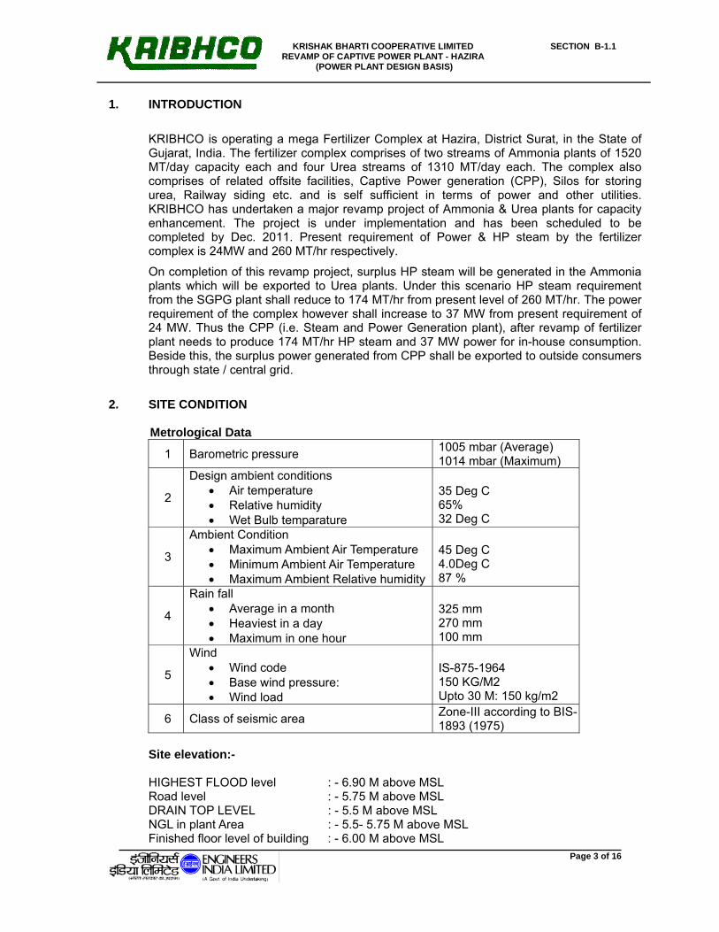
KRIBHCO is operating a mega Fertilizer Complex at Hazira, District Surat, in the State of Gujarat, India. The fertilizer complex comprises of two streams of Ammonia plants of 1520 MT/day capacity each and four Urea streams of 1310 MT/day each. The complex also comprises of related offsite facilities, Captive Power generation (CPP), Silos for storing urea, Railway siding etc. and is self sufficient in terms of power and other utilities. KRIBHCO has undertaken a major revamp project of Ammonia & Urea plants for capacity enhancement. The project is under implementation and has been scheduled to be completed by Dec. 2011. Present requirement of Power & HP steam by the fertilizer complex is 24MW and 260 MT/hr respectively.
On completion of this revamp project, surplus HP steam will be generated in the Ammonia plants which will be exported to Urea plants. Under this scenario HP steam requirement from the SGPG plant shall reduce to 174 MT/hr from present level of 260 MT/hr. The power requirement of the complex however shall increase to 37 MW from present requirement of 24 MW. Thus the CPP (i.e. Steam and Power Generation plant), after revamp of fertilizer plant needs to produce 174 MT/hr HP steam and 37 MW power for in-house consumption. Beside this, the surplus power generated from CPP shall be exported to outside consumers through state / central grid.
2. SITE CONDITION
Metrological Data
1 Barometric pressure 1005 mbar (Average) 1014 mbar (Maximum)
2
Design ambient conditions • Air temperature • Relative humidity • Wet Bulb temparature
35 Deg C 65% 32 Deg C
3
Ambient Condition • Maximum Ambient Air Temperature • Minimum Ambient Air Temperature • Maximum Ambient Relative humidity
45 Deg C 4.0Deg C 87 %
4
Rain fall • Average in a month • Heaviest in a day • Maximum in one hour
325 mm 270 mm 100 mm
5
Wind • Wind code • Base wind pressure: • Wind load
IS-875-1964 150 KG/M2 Upto 30 M: 150 kg/m2
6 Class of seismic area Zone-III according to BIS-1893 (1975)
Site elevation:- HIGHEST FLOOD level : - 6.90 M above MSL Road level : - 5.75 M above MSL DRAIN TOP LEVEL : - 5.5 M above MSL NGL in plant Area : - 5.5- 5.75 M above MSL Finished floor level of building : - 6.00 M above MSL

KRISHAK BHARTI COOPERATIVE LIMITED REVAMP OF CAPTIVE POWER PLANT - HAZIRA
(POWER PLANT DESIGN BASIS)
SECTION B-1.1
Page 4 of 16
3. DESIGN DATA 3.1 FUELS & FUEL SPECIFICATION
Natural Gas at CPP battery Limit shall be available at 42.0 KG/Cm2g & at ambient temperature. Natural Gas specifications shall be as per Annexure – II.
3.2 POLLUTION CONTROL The stack pollutions level shall not exceed the following limits as a minimum requirement:-
It shall be ensured to maintain the emission from CPP as per Norms/Guidelines of Central Pollution Control Board / Gujarat State Pollution Control Board.
3.3 NOISE LEVEL The noise level shall not exceed than 85 dBa at a distance of 1 meter from source of
individual Equipment. The noise in CPP and adjacent area shall be restricted within limit specified by statutory standard for Pollution control.
4. CAPTIVE POWER PLANT (CPP) The Captive Power Plant (CPP) of KRIBHCO Fertilizer complex is intended to meet the
revised internal steam and power requirement. CPP is to be designed to export 72 ± 2 MW power and 190 TPH of peak HP steam from CPP block. Part of the total exported power shall be used in the fertilizer complex and rest of the surplus power shall be sold to grid.
4.1 BRIEF PLANT DESCRIPTION
Existing configuration of CPP: Existing steam and power requirement of fertilizer complex is 260 TPH and 24 MW which used to be met through gas fired utility boilers and STGs.
Existing Captive Powe Plant (CPP) consists of three high pressure boilers, two extraction cum condensing type Steam Turbine Generator sets, two deaerators, four boiler feed water pumps, two HP heaters, two make-up tanks and make-up pumps as specified below. Existing facilities which are in common shall be utilized to the maximum extent i.e. deaerator, boiler feed water pumps, two make-up tanks and make-up pumps etc shall be utilized for the new GTG-HRSGs. After installing the new equipment in the CPP, existing boilers and STGs will not be required for operation for normal operation, however for upset conditions or under shutdown of new GTG- HRSG existing boilers and STGs will be put in operation to meet the demand.
The Existing CPP consists of the following major equipment.
1. Utility Boilers:-
I. Numbers :- 3
II. Capacity :- 275 TPH each
S.N. Parameter Type of Fuel Mg/NM3 1 Oxides of Nitrogen (NOX) Gas Firing 100 ppm / 180 mg/m3

KRISHAK BHARTI COOPERATIVE LIMITED REVAMP OF CAPTIVE POWER PLANT - HAZIRA
(POWER PLANT DESIGN BASIS)
SECTION B-1.1
Page 5 of 16
III. SH outlet pressure:- 105 kg/cm2g
IV. SH outlet temperature:- 510 deg C
V. Fuel:- Dual Fuel (Natural Gas & NGL/Naphtha)
2. Steam Turbine Generator:-
I. Numbers :- 2
II. Capacity: 15 MW each
III. Type :- Double Extraction cum condensing
IV. Inlet Steam parameter :- HP steam 101 kg/cm2 abs & 505 deg C
V. MP controlled extraction: 14 ± 1 kg/cm2 abs
VI. LP uncontrolled extraction:- 2.7 kg/cm2 abs
VII. Speed :- 7500 rpm
3. Deaerator:-
I. Numbers:- 2
II. Type:- Spray cum tray
III. Water output :- 315 TPH
IV. Maximum working/ design pressure:- 1.725 /2.03 kg/cm2 abs
V. Maximum working / design temperature:- 115 /155 deg C
VI. Oxygen in outlet water ml/L:- 0.0005 ml/l
4. Boiler Feed pumps:-
I. Numbers:- 4 II. Capacity:- 315 TPH
III. Discharge pressure/shut off head: 137.6 / 178 kg/cm2 g.
IV. Type :- Two motor driven and two steam turbine driven
5. Make-up water tank:
i. No. of Tank- 2 Nos.
ii. Design pressure : 100 mmwc
iii. Design code: API Spec 12 D
iv. Design Temp: 100 Deg C
v. Duty- Tones : 140
vi. Plate material: BS 4360-43A
6. Make-up water pump:
I. No. of pump: Three (03)
II. Type: 6”/6” D.ME.K MEDIVANE (YP 18.2K)
III. Discharge quantity: 285.4 TPH
IV. Delivery head: 6.77 kg/cm2g
V. Shut of Head: 9.0 kg/cm2g

KRISHAK BHARTI COOPERATIVE LIMITED REVAMP OF CAPTIVE POWER PLANT - HAZIRA
(POWER PLANT DESIGN BASIS)
SECTION B-1.1
Page 6 of 16
Proposed Configuration for Captive Power Plant: Normal steam and power requirement after revamp of fertilizer plant will be 37 MW and 174 TPH. Configuration of the CPP shall consist of either one or two similar gas turbine generator(s) (GTG) and supplementary fired Heat recovery Steam Generator (HRSG) downstream of each GTG. The capacity details of the additional equipment shall be as per Cl. No. 4.2 bellow. Existing Deaerator, make-up water pump and BFPs (Boiler feed water pumps) will be utilized to feed the BFW (boiler feed water) to the new HRSG(s).
4.2 BRIEF SCOPE OF WORK AND DESCRIPTION
1. Gas Turbine Generator (GTG) Type - Industrial Heavy Duty Type Quantity - 1 No. or 2 Nos. of similar type and model. Capacity (Min) - 1 x (72 ± 2) MW or 2 x (36 ± 1) MW
The use of Vapour absorption type chiller* is also acceptable in case single GTG is offered by the Bidder. However power augment limit from chiller is upto 72 MW export power only.
If required provision of DM Water /Steam injection limited to the extent for meeting only NOx emission should be provided. However GTG capacity (72 ± 2 MW) shall be considered without any DM water/ steam injection.
(*Use of evaporative cooler for power augmentation is not acceptable. Standard specification for vapour absorption refrigeration package is attached as annexure - VII)
Medium for NOx control - DM-WATER/ STEAM (if required) Guarantee fuel - Natural Gas (as per Annexure - II). Design Ambient Temperature - 35 deg C Design RH - 65 % Barometric pressure - 1005 mbar
2. Heat Recovery Steam Generators (HRSGs)
Quantity - 1 No. or 2 nos. of similar type and model
(Associated with GTG) Type - Horizontal, Natural circulation with supplementary
firing Steam Parameters. - HP (to suit the parameter at tap-off point) Capacity (Min.)/HRSG - 190* / 2 x 95* TPH Steam Generation (with
supplementary firing) (bidder to confirm) Fuel: - Natural Gas. PLC based BMS shall be provided. Design Code - Indian Boiler Regulation (IBR) latest Edition.

KRISHAK BHARTI COOPERATIVE LIMITED REVAMP OF CAPTIVE POWER PLANT - HAZIRA
(POWER PLANT DESIGN BASIS)
SECTION B-1.1
Page 7 of 16
(*HRSG capacity is to be selected so that net export of 190 TPH HP steam from CPP after meeting internal steam consumption i.e. gas heating, chiiler etc. is ensured.) Turn down of HRSG - : ≤ 30% of MCR (@ Rated steam pressure &
temperature) 3. GAS CONDITIONING SKID:-
Gas conditioning skid shall be suitable for CPP requirement. Gas conditioning skid shall consists of 1x100% Knock out drum (gas Scrubber) for GTG/HRSG stream. Pressure reduction valves, filter etc. shall be 2x100% for each services i.e. GTGs & HRSGs. If gas heating is required, 2x100% steam gas heater and 1x100% electric gas heater shall be provided. Gas line from gas condition skid to Gas turbine inlet shall be properly insulated. Suitable steam/Electric tracing system shall be provided if required.
4. COOLING TOWER ( for BLACK START & NORMAL OPERAION):-
Cooling water requirement for the new GTG and HRSG shall be met through separate Cooling Tower and the same shall be in bidder’s scope. Cooling tower capacity shall be of based on cooling water required for GTGs and HRSGs. Bidder shall also provide 2 x 100% cooling water pumps. Each pump shall be suitable for meeting the Cooling water requirement of all GTGs and HRSGs along with other equipment in their scope. All pumps shall discharge cooling water to a common discharge header and all the cooling water shall be fed through this header. A tapping form discharge header is to be provided for future similar unit. All pumps shall be motor driven. (One of these cooling water pumps shall be sourced from both normal as well as emergency power) Cooling water system shall have also provision of hooking up at Battery limit with the existing cooling water system with isolation valves.
5. Either GTG shall be provided with diesel engine for cranking of GTG during starting up or
GTG shall consist of a static frequency converter (SFC) so as gas turbine generator shall act as starting motor for cranking during start-up through grid. Emergency power for black start shall be made available at battery limit. Bidder to submit requirement of emergency power along with bid and make provision for supply of emergency power in their MCC.
The Ratings / Capacities of the HRSGs, given above are only minimum. Net export of 190 TPH of HP steam from CPP shall be ensured. Tentative layout is attached as Annexure – III.
4.3 Integration of Additional Power Equipments with existing set-up:
All existing system shall be used to the maximum extent possible. Some major present
facilities as follows are to be utilized. • Existing HP steam export header to fertiliser complex. The proposed new HRSGs steam
shall be connected to this header.

KRISHAK BHARTI COOPERATIVE LIMITED REVAMP OF CAPTIVE POWER PLANT - HAZIRA
(POWER PLANT DESIGN BASIS)
SECTION B-1.1
Page 8 of 16
• LP steam generated shall be exported to existing CPP for use in Deaerator. LP steam header shall be connected to existing LP steam header of existing CPP.
• Existing Feed water system- Feed water required for new HRSG shall be sourced from this header.
• Existing Condensate system: - Condensate as required for Make-up heater (MUH) of new HRSG shall be provided from existing header. Existing make up pump (refer cl. 4.1 sl. No.5 of this document) shall be used to source the condensate to MUH. Bidder to confirm the parameter at the tap off point. Bidder to provide isolation valves at inlet and outlet header along with control valve to each MUH.
• Condensate after heating in HRSG shall be sent to existing Deaerator.
• Existing Dearator- The existing Deaerators shall be used to feed BFW to HRSG.
• Make-up for cooling water system: - Separate cooling system to be provided for meeting the GTG-HRSG cooling water requirement for normal as well as black start. Make-up for cooling tower shall be provided at battery limit. However provision for hook up with existing cooling circuit at Battery limit is also to be provided.
• Existing Instrument air system- Instrument air required for CPP shall be sourced from existing IA system.
• Plant air system: - To be Sourced from existing system.
• Service water system: - To be sourced from existing system.
• Drinking water system: - To be sourced from existing system.
• Fuel system- Fuel gas for gas conditioning skid (new GTGs & HRSGs) shall be supplied at CPP battery limit.
• Electrical system- Refer electrical specification.
• Control system - Refer Instrument specification.
4.3.1 STEAM The steam generated from new Heat Recovery Steam Generator (HRSG) is to be hooked
up to existing HP header located in existing CPP. All existing utility boilers are connected to this header and HP steam demand of the fertilizer plant will be met through this header from CPP.
Header from HRSGs shall be designed to export of 300 TPH of BFW and HP steam to existing HP header. (Bidder to note that with future HRSG max HP export to the fertilizer complex shall be 300 TPH).
Bidder to note that CBD vent is also to be connected with existing LP header to optimise water and fuel consumption.
KRISHAK BHARTI COOPERATIVE LIMITED REVAMP OF CAPTIVE POWER PLANT - HAZIRA
(POWER PLANT DESIGN BASIS)
SECTION B-1.1
Page 9 of 16
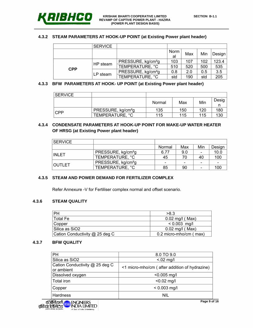
4.3.2 STEAM PARAMETERS AT HOOK-UP POINT (at Existing Power plant header)
4.3.3 BFW PARAMETERS AT HOOK- UP POINT (at Existing Power plant header)
4.3.4 CONDENSATE PARAMETERS AT HOOK-UP POINT FOR MAKE-UP WATER HEATER OF HRSG (at Existing Power plant header)
4.3.5 STEAM AND POWER DEMAND FOR FERTILIZER COMPLEX Refer Annexure -V for Fertiliser complex normal and offset scenario.
4.3.6 STEAM QUALITY
4.3.7 BFW QUALITY
SERVICE Norm
al Max Min Design
CPP HP steam PRESSURE, kg/cm²g 103 107 102 123.4
TEMPERATURE, °C 510 520 500 535
LP steam PRESSURE, kg/cm²g 0.8 2.0 0.5 3.5 TEMPERATURE, °C std 190 std 205
SERVICE
Normal Max Min Design
CPP PRESSURE, kg/cm²g 135 150 120 180 TEMPERATURE, °C 115 115 115 130
SERVICE Normal Max Min Design
INLET PRESSURE, kg/cm²g 6.77 9.0 - 10.0 TEMPERATURE, °C 45 70 40 100
OUTLET PRESSURE, kg/cm²g - - - - TEMPERATURE, °C 85 90 - 100
PH >8.3 Total Fe 0.02 mg/l ( Max) Copper < 0.003 mg/l Silica as SiO2 0.02 mg/l ( Max) Cation Conductivity @ 25 deg C 0.2 micro-mho/cm ( max)
PH 8.0 TO 9.0 Silica as SiO2 <.02 mg/l Cation Conductivity @ 25 deg C or ambient <1 micro-mho/cm ( after addition of hydrazine)
Dissolved oxygen <0.005 mg/l Total iron <0.02 mg/l Copper < 0.003 mg/l
Hardness NIL

KRISHAK BHARTI COOPERATIVE LIMITED REVAMP OF CAPTIVE POWER PLANT - HAZIRA
(POWER PLANT DESIGN BASIS)
SECTION B-1.1
Page 10 of 16
4.3.8 DM WATER QUALITY:-
4.3.9 CONDENSATE QUALITY:-
4.3.10 MAKE-UP WATER QUALITY FOR COOLING TOWER:- Sr. Parameter Specification
1. pH 7.0 –8.5
2. Conductivity (micro mhos /cm) 225 –330
3. Turbidity in NTU 1.0 -5.0
4. Free Residual chlorine mg/l NT-0.5
5. Silica as SiO2 mg/l 15.0-25.0
6. Total Hardness as CaCO3 mg/l 100-130
7. Calcium Hardness as CaCO3 mg/l 45 –75
8. Chloride as CaCO3 mg/l 20 –40
9. Total alkalinity as CaCO3 mg/l 80 –125
10. Sodium as CaCO3 mg/l 30 –60
11. Sulphate as CaCO3 mg/l 10 –30
12. Total aerobic count (colonies/ml) 500-1000
13. Sulphate reducing bacteria
(Colonies / 100ml)
0 –10
14. Phosphate as PO4 NIL
15. Soluble Iron as Fe mg/l < 0.1
PH 6.5 TO 7.0 Silica as SiO2 <.01 ppm Conductivity 0.5 MICRO-MHO/CM PRESSURE 3.5 KG/CM2 TEMPERATURE 45 Deg C
HARDNESS NIL
PH 6.8 TO 8.0 Silica as SiO2 <.01 ppm Conductivity 0.5 MICRO-MHO/CM PRESSURE 3.5 KG/CM2 TEMPERATURE 45 Deg C HARDNESS NIL

KRISHAK BHARTI COOPERATIVE LIMITED REVAMP OF CAPTIVE POWER PLANT - HAZIRA
(POWER PLANT DESIGN BASIS)
SECTION B-1.1
Page 11 of 16
4.4 UTILITY Refer utility List at Annexure - I
5. DESIGN CONSIDERATIONS FOR CPP
5.1 The process steam and plant power requirements have to be met by the CPP throughout the year.
5.2 Burner operation of GTG & HRSG shall be from DCS only with the provision of local manual operation.
5.3 Any trip signal for HRSG, fuel burner and GTG shall have 2 out of 3 logic.
5.4 The Heat and Mass balance of the CPP for all the operating scenarios are required to be worked out by Bidder for the following cases and submitted with bid.
a) CPP configuration case A - Normal configuration shall be based on 72 ± 2 MW net power output from CPP ( one/ two GTG on base load) and export steam output of 190 TPH from one / two HRSGs.
b) CPP configuration case B - Normal configuration shall be based on 72 ± 2 MW net power output from CPP ( one/ two GTG on base load) and maximum export steam output of from one / two HRSGs without supplementary firing.
c) CASE-C.1 – GTG base load without chiller (if chiller not provided) and steam output from HRSGs is 40% of MCR.
d) CASE-C.2 – GTG base load with chiller (if chiller provided) and steam output from HRSGs is 40% of MCR.
e) CASE-C.3 – GTG base load without chiller (if chiller provided) and MCR steam output from HRSGs.
f) CASE-D.1 –GTG @ 40% of base load without chiller (if chiller not provided)) and steam output from HRSG is 190 TPH
g) CASE-D.2 –GTG @ 40% of base load with chiller (if chiller provided) and steam output from HRSG is 190 TPH
h) CASE-E.1 – GTG @ 30% of base load without chiller (if chiller not provided) and maximum steam output from HRSG.
i) CASE-E.2 – GTG @ 30% of base load with chiller (if chiller provided) and maximum steam output from HRSG.
5.5 The proposed Power Plant shall be capable of operation in synchronisation with the grid as well as with facility for islanded mode operation.
5.6 Provision shall be kept for control of steam and power load sharing between various steam generators and power generators respectively.
5.7 All Steam safety valves including start-up vent exhaust shall be provided with Silencer.
5.8 Following Flow meters (FE/FT/FI/FAH/FAL) to be provided as a minimum i. On steam headers from each HRSGs from SH outlet

KRISHAK BHARTI COOPERATIVE LIMITED REVAMP OF CAPTIVE POWER PLANT - HAZIRA
(POWER PLANT DESIGN BASIS)
SECTION B-1.1
Page 12 of 16
ii. All utility (CW, IA, service air, LP steam from CBD tank etc..) line at CPP at Battery limit.
iii. Total gas flow at Battery limit
iv. Fuel gas to individual GTG and HRSG
v. BFW line to each HRSG
vi. BFW for each attemperator
vii. Condensate to each MUH
viii. DM water / steam to each GTG for NOx control
5.9 Following minimum motor operated valve with provision of manual operation shall be provided:-
I. Main steam and its bypass valve along with manual isolation valve.
II. Startup vent isolation valve along with manual isolation valve.
III. 1st Isolation valve of feed control valves.
5.10 Bidder to design the CPP system so as to meet the battery limit pressure and temperature
design condition as per the bid doc at all operating conditions.
5.11 Each control valve 2” and above shall have block and bypass valves having same capacity of control valve.
5.12 All integral pressure equalisation valves shall be motorised if the concerned main valve is motorised.
5.13 Control valves shall be provided with motorised upstream isolating valve and downstream manual isolating valves for feed control station.
5.14 Feed Control station shall be provided with 2 Nos. (each 100 % capacity) control valves (i.e. one stand by) and one additional split control valve to be offered for low load/ start-up requirement. For all other control station, 1x100% control valve along with motorised bypass valve of equal capacity shall be provided.
5.15 HP steam and Boiler feed water line to be sized (with hook-up provision with double isolation valve) for future expansion of CPP with another GTG and HRSG (same size).
5.16 All national, international and local statutory regulation (latest edition) shall be complied with.
5.17 All gas vent exhaust shall be left at safe height and location.
5.18 Copper and copper bearing alloy shall not be used in heat exchangers.
5.19 Bidder to provide isolation valve with flow element at all the tapping points / hook-ups ( HP Steam/BFW/Make-up water, all utilities etc) of the existing system.
KRISHAK BHARTI COOPERATIVE LIMITED REVAMP OF CAPTIVE POWER PLANT - HAZIRA
(POWER PLANT DESIGN BASIS)
SECTION B-1.1
Page 13 of 16
6. SPECIAL DESIGN REQUIREMENTS FOR MAJOR EQUIPMENTS 6.1 Gas Turbine Generator (GTG) 6.1.1 Gas Turbine shall be Industrial Heavy Duty Type suitable for outdoor installation. The Gas
Turbine shall be capable of withstanding full load rejection without over speed trip while running on Natural gas.
6.1.2 Steam / D.M Water shall be used if required only for NOX control in GTG.
6.1.3 Gas Turbine shall be supplied from established gas turbine manufacturer having adequate design engineering, manufacturing and testing facilities.
6.1.4 The gas turbine model offered shall be from the existing regular production range of the vendor, and the rating offered shall be based on internationally published rating.
6.1.5 Gas turbine shall be identical in construction (i.e. no. Of shafts, no. Of stages in each compressor section, no. Of stages in each turbine section, mechanical design, material of construction of blades, nozzles, discs and combustors, cooling of blades, nozzles and disc, combustion system, starting system), type of turbine temperature control and in performance at ISO conditions in terms of Power rating for the type of fuel specified ( liquid and/or gas fuel), heat rate, firing/cycle temperature, power turbine inlet temperature, exhaust temperature, overall pressure ratio, airflow and speed of each shaft as compared to atleast TWO UNITS produced, tested and supplied by the vendor and must have completed minimum 8000 hours of trouble free operation at the specified operating conditions, on the date of inquiry.
6.2 Heat Recovery Steam Generator (HRSG)
6.2.1 The Heat Recovery Steam Generators shall be of natural circulation, single drum and single pressure type. It shall have supplementary firing. Economisers shall be non-steaming at all loads and turndown. HP steam will be generated in HRSG. Natural gas shall be normally fired in the HRSGs. The burner shall be ultra Low-NOx type.
6.2.2 Bidder to provide make up water heater (MUH) in each HRSG. Bidder to ensure that
- The metal temperatures of the MUH shall be maintained minimum 5 deg C above acid dew point under all conditions.
- There shall be no steaming inside the make-up water preheater section even at low flow and lowest turndown condition.
- The basis of MUH design:-
o Inlet condensate flow equal to MCR of HRSG and temperature 45 deg C
o Outlet temperature shall be 85 deg C maximum (Design condition 90 deg C).
o For the above cold Condensate shall be tapped off from existing make-up pump discharge header and the hot condensate shall be connected to the inlet of existing dearator level control valve.

KRISHAK BHARTI COOPERATIVE LIMITED REVAMP OF CAPTIVE POWER PLANT - HAZIRA
(POWER PLANT DESIGN BASIS)
SECTION B-1.1
Page 14 of 16
- It shall be ensured that the preheat section is designed for dry running also. MOC of makeup water heater shall be SS 304 minimum
- Bidder to take tapping of cold condensate from existing condensate to dearater header (at existing CPP) for MUH and supplying the hot condensate from MUH to Dearator (existing).
6.2.3 Only seamless tubes shall be used. First few rows of the tubes shall be plain tubes and rest of the tubes shall be finned. Superheater tubes shall not be directly facing the duct burners and should be provided with screen tube evaporator zone.
6.2.4 The design of HRSG shall ensure minimum pressure drop through the HRSG and the flow through the stack.
6.2.5 Steam drum shall be designed with minimum 2 minutes of capacity of storage between normal water level and drum dry level.
6.2.6 Necessary dosing System including unloading, storage etc. of chemicals at various points to maintain BFW and boiler water quality, which is required, finally to ensure the desired steam purity shall be provided.
6.2.7 Continuous on-line stack monitoring system consisting of sampling probes, piping, analysers, etc. for analysis of SOx, NOx, CO & SPM shall be provided on the main stack of HRSG. The analysers and recorder shall be located in a suitable air conditioned enclosure near the stack.
6.2.8 Blow down from HRSGs shall be collected in pit after being quenched with service water to 60 Deg C. Water shall be pumped to battery limit at 3.5 kg/cm2g pressure.
6.2.9 Diverter damper shall be modulating control type so that pressurization curve can be maintained.
6.2.10 GTG shall have its individual bypass stack. The height of bypass stack shall be 30 Meters. Individual main stack for each HRSG shall be provided. The height of main stack shall be as per the formula given below or 40 m whichever is higher.
H=14(Q) 0.3
Where, H= Stack Height in Meters
Q=Total SOx emission in Kg/Hr.
All stack shall be designed with minimum corrosion allowance of 3.0 mm. Material of stack shall be suitable for maximum temperature envisaged and as specified elsewhere in the document.
6.2.11 The layout of the flue gas ducts connected to the chimney shall ensure adequate head room for passage of erection and maintenance on the HRSG as required. Necessary air-conditioned enclosure for pollution control analysers shall be provided.
6.2.11.1 HRSG to be sized to achieve rated steam temperature in the following conditions:-
I. Turn down: - 30% of MCR at all ambient temperature.

KRISHAK BHARTI COOPERATIVE LIMITED REVAMP OF CAPTIVE POWER PLANT - HAZIRA
(POWER PLANT DESIGN BASIS)
SECTION B-1.1
Page 15 of 16
II. Between 40% to 100% of GTG base load at all ambient temperature HRSG shall be
able to generate MCR capacity with specified parameters.
III. Between 30% to 40% of GTG base load at all ambient temperature HRSG shall be
able to meet steam parameters however stem flow may be lower.
6.2.12 Separate HP chemical dosing systems shall be provided for each HRSG.
6.2.13 Following on-line analyzer shall be provided in SWAS system:-
1 pH, Conductivity at BFW header. 2 pH, Conductivity at condensate inlet to MUH 3 pH & Conductivity for superheated steam and drum water for HRSG.
6.3 DESIGN MARGINS ON VARIOUS EQUIPMENTS
Burners ( each) 10% margin Black start cooling water pump
10% margin on flow
Seal air fan 20% margin on flow 25% on head to arrive at test block rating.
7.0 REDUNDANCY PHILOSOPHY
The following shall be the redundancy philosophy for the major equipments:
Dosing Pump for each chemical for each HRSG
2 No. (1W+ 1 S/B) All motor driven
Seal Air fan each HRSG-GTG stream
2 No. (1W+ 1 S/B) All motor driven
Scanner air fan for each HRSG
2 No. (1W+ 1 S/B) One AC motor driven and one DC driven
Cooling water pump 2 No. (1W+ 1 S/B) To meet the cooling water for GTGs and HRSGs of CPP
8.0 BUILDINGS/SHED
GTGs shall be put under the shed along with EOT crane for maintenance. Specification of
the crane is specified elsewhere in the document. Separate room for the SWAS system
and analyzer room shall be provided. The control room for Proposed CPP shall be
accommodated in existing control room however room shall be required for local operator.

KRISHAK BHARTI COOPERATIVE LIMITED REVAMP OF CAPTIVE POWER PLANT - HAZIRA
(POWER PLANT DESIGN BASIS)
SECTION B-1.1
Page 16 of 16
9.0 ANNEXURES:
Attached annexure are as follows:-
I. Utility list at CPP II. Natural gas specification.
III. Tentative Plot Plan / Equipment Layout of Proposed CPP. IV. HSD specification. V. Normal and other abnormal operating scenario.
VI. Inter-Face diagram. VII. Standard specification for Vapour absorption Refrigeration package ( 6-36-007 rev1)