Embed Size (px)
Citation preview
For Training Purposes OnlySept 04
17-i
P I L O T T R A I N I N G G U I D E
POWER PLANT
Chapter 17: Power Plant
TABLE OF CONTENTS
Page
Introduction .......................................................................................................................17-1Description ........................................................................................................................17-2
Engine Assembly and Airflow......................................................................................17-2Engine Modules ..........................................................................................................17-3Full Authority Digital Electronic Control (FADEC) .......................................................17-4Electronic Engine Controller (EEC).............................................................................17-5Engine Indications.......................................................................................................17-8Interturbine Temperature (ITT)....................................................................................17-9ITT Indication ............................................................................................................17-10N2 Indication .............................................................................................................17-11Fuel Flow...................................................................................................................17-11Fuel Flow Indication ..................................................................................................17-12Oil Temperature ........................................................................................................17-12Oil Temperature Indication........................................................................................17-12Oil Pressure ..............................................................................................................17-12Oil Pressure Indication ..............................................................................................17-13Engine Oil System.....................................................................................................17-13Engine Oil Heat Management System......................................................................17-15Oil Replenishment System........................................................................................17-16Oil Replenishment Panel...........................................................................................17-17Oil Replenishment Schematic ...................................................................................17-18Engine Fuel System..................................................................................................17-19
Fuel System Schematic ......................................................................................17-21Engine Bleed Air System ..........................................................................................17-22Thrust Management System.....................................................................................17-23
Thrust Levers ......................................................................................................17-23Engine Pressure Ratio (EPR) .............................................................................17-26EPR Rating Mode Selection................................................................................17-27FMS Selection (EPR) ..........................................................................................17-29EPR Control ........................................................................................................17-30N1 (Fan) ..............................................................................................................17-31N1 Control ...........................................................................................................17-32N2 (HP Compressor)...........................................................................................17-33Engine Idle Control..............................................................................................17-34
Engine Fire Detection System...................................................................................17-35Engine Vibration Monitoring System (EVMS) ...........................................................17-36
EVMS Indication..................................................................................................17-36Starting and Ignition ..................................................................................................17-37
Starter Air Valve (SAV) .......................................................................................17-38Air Turbine Starter (ATS) ....................................................................................17-38Ignition System....................................................................................................17-39Engine Run Switches ..........................................................................................17-41
17-ii For Training Purposes OnlySept 04
P I L O T T R A I N I N G G U I D E
POWER PLANT
Engine Starting.................................................................................................... 17-42Auto Start - Ground............................................................................................. 17-42Rotor Bow ........................................................................................................... 17-44Auto Start - Air..................................................................................................... 17-45Manual Start - Ground......................................................................................... 17-45
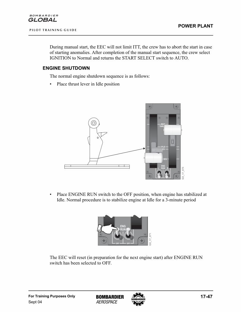
Engine Shutdown...................................................................................................... 17-47Dry Cranking ....................................................................................................... 17-48Wet Cranking ...................................................................................................... 17-48
Starting Anomalies.................................................................................................... 17-49Automatic Ground Start Abort ............................................................................. 17-49Manual Ground Start Abort ................................................................................. 17-49Automatic Air Start Abort..................................................................................... 17-49
Auto-Relight .............................................................................................................. 17-50Quick Relight............................................................................................................. 17-50Autothrottle System................................................................................................... 17-51
Autothrottle (A/T) Data Sources .......................................................................... 17-51A/T Limiting ......................................................................................................... 17-51A/T Monitoring..................................................................................................... 17-52Electronic Thrust Trim System (ETTS) ............................................................... 17-52SYNC Mode Selection ........................................................................................ 17-53N1 SYNC On....................................................................................................... 17-53N2 SYNC On....................................................................................................... 17-54EPR CMD SYNC On........................................................................................... 17-54N1, N2, EPR CMD SYNC Off.............................................................................. 17-55Sync Annunciation .............................................................................................. 17-55A/T 1 or 2 Select ................................................................................................. 17-56A/T Engagement/Disengagement ....................................................................... 17-56A/T Disengagement ............................................................................................ 17-57A/T Disengagement and Manual Override.......................................................... 17-58A/T Mode Operation............................................................................................ 17-59Takeoff Thrust Control Mode .............................................................................. 17-60Takeoff Thrust Hold Control Mode ...................................................................... 17-60Flight Level Change Thrust Control Mode .......................................................... 17-61Airspeed Control Mode ....................................................................................... 17-62Retard Mode ....................................................................................................... 17-63Go Around Thrust Control Mode ......................................................................... 17-63
Thrust Reverser System ........................................................................................... 17-64Thrust Reverser .................................................................................................. 17-64Reverse Thrust Operation................................................................................... 17-66Reverser Components ........................................................................................ 17-67Directional Control Unit ....................................................................................... 17-67Reverse Thrust Levers........................................................................................ 17-69Reverser System Lockout ................................................................................... 17-70
Power Plant EICAS Messages ................................................................................. 17-71EMS Circuit Protection.............................................................................................. 17-75
For Training Purposes OnlySept 04
17-1
P I L O T T R A I N I N G G U I D E
POWER PLANT
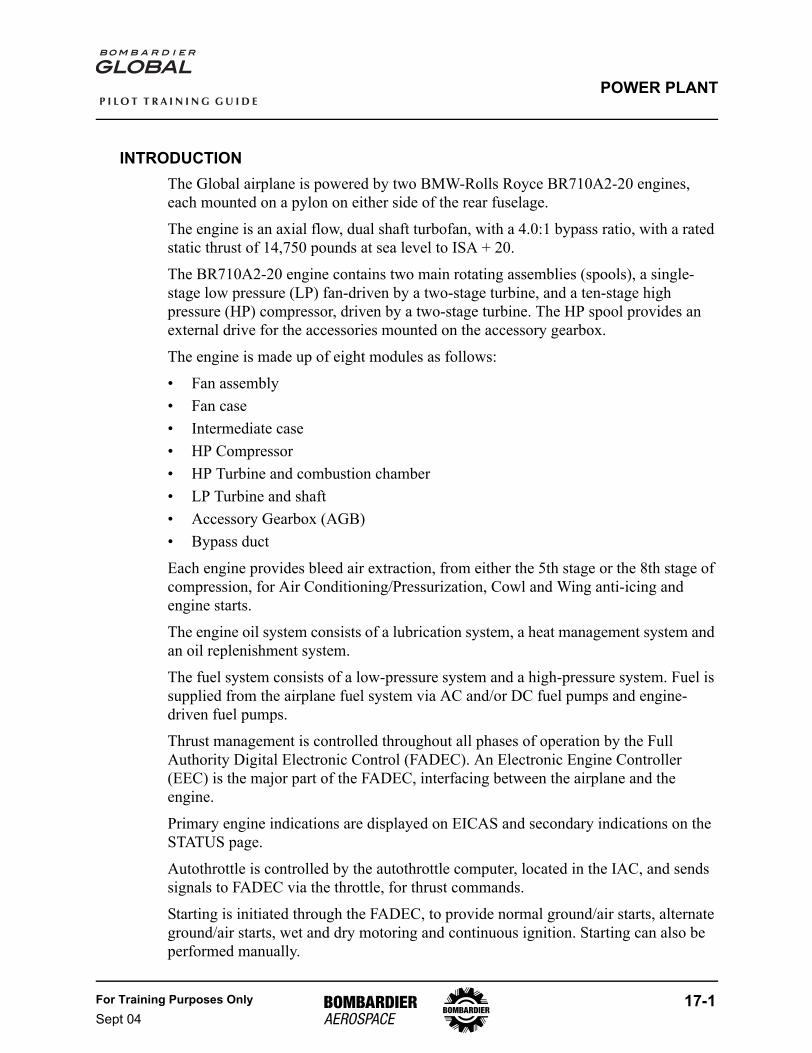
INTRODUCTIONThe Global airplane is powered by two BMW-Rolls Royce BR710A2-20 engines, each mounted on a pylon on either side of the rear fuselage.
The engine is an axial flow, dual shaft turbofan, with a 4.0:1 bypass ratio, with a rated static thrust of 14,750 pounds at sea level to ISA + 20.
The BR710A2-20 engine contains two main rotating assemblies (spools), a single-stage low pressure (LP) fan-driven by a two-stage turbine, and a ten-stage high pressure (HP) compressor, driven by a two-stage turbine. The HP spool provides an external drive for the accessories mounted on the accessory gearbox.
The engine is made up of eight modules as follows:
• Fan assembly• Fan case• Intermediate case• HP Compressor• HP Turbine and combustion chamber• LP Turbine and shaft• Accessory Gearbox (AGB)• Bypass duct
Each engine provides bleed air extraction, from either the 5th stage or the 8th stage of compression, for Air Conditioning/Pressurization, Cowl and Wing anti-icing and engine starts.
The engine oil system consists of a lubrication system, a heat management system and an oil replenishment system.
The fuel system consists of a low-pressure system and a high-pressure system. Fuel is supplied from the airplane fuel system via AC and/or DC fuel pumps and engine-driven fuel pumps.
Thrust management is controlled throughout all phases of operation by the Full Authority Digital Electronic Control (FADEC). An Electronic Engine Controller (EEC) is the major part of the FADEC, interfacing between the airplane and the engine.
Primary engine indications are displayed on EICAS and secondary indications on the STATUS page.
Autothrottle is controlled by the autothrottle computer, located in the IAC, and sends signals to FADEC via the throttle, for thrust commands.
Starting is initiated through the FADEC, to provide normal ground/air starts, alternate ground/air starts, wet and dry motoring and continuous ignition. Starting can also be performed manually.
17-2 For Training Purposes OnlySept 04
P I L O T T R A I N I N G G U I D E
POWER PLANT
The thrust reverser system is operated by the airplane hydraulic system and is controlled by the EEC.
Vibration monitoring system provides signals indicating N1 (Fan) and N2 (HP compressor) vibration levels on each engine.
Fire detection is provided by dual element sensor assemblies connected in series to provide two independent sensing loops. Two fire bottles are located at the rear of the airplane.
DESCRIPTION
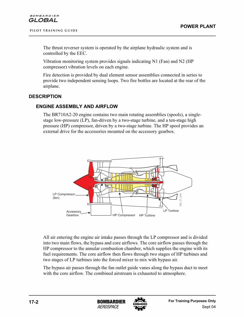
ENGINE ASSEMBLY AND AIRFLOWThe BR710A2-20 engine contains two main rotating assemblies (spools), a single-stage low-pressure (LP), fan-driven by a two-stage turbine, and a ten-stage high pressure (HP) compressor, driven by a two-stage turbine. The HP spool provides an external drive for the accessories mounted on the accessory gearbox.
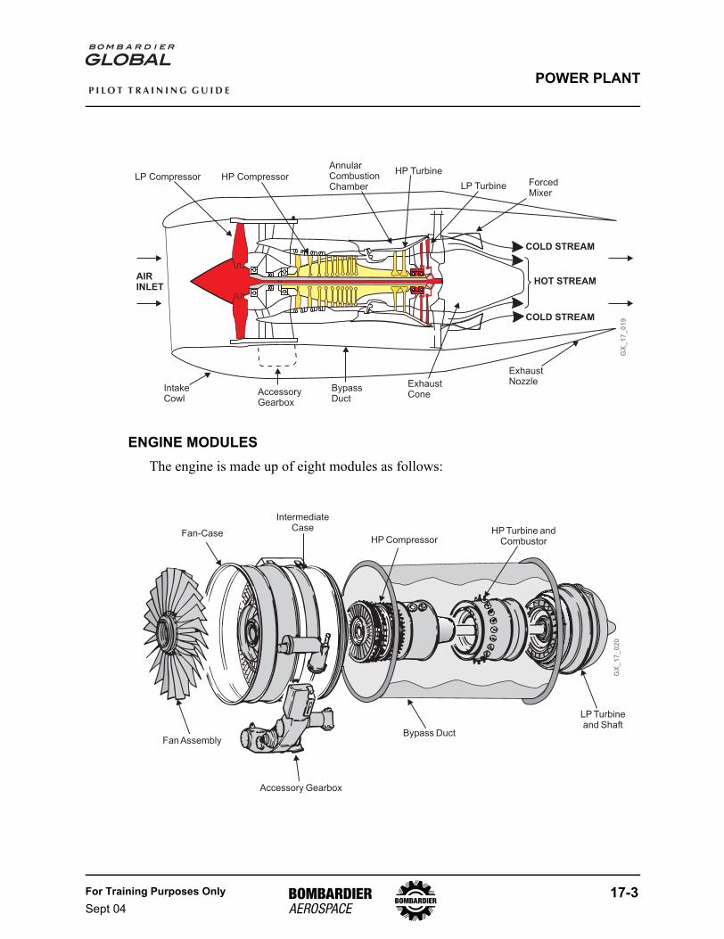
All air entering the engine air intake passes through the LP compressor and is divided into two main flows, the bypass and core airflows. The core airflow passes through the HP compressor to the annular combustion chamber, which supplies the engine with its fuel requirements. The core airflow then flows through two stages of HP turbines and two stages of LP turbines into the forced mixer to mix with bypass air.
The bypass air passes through the fan outlet guide vanes along the bypass duct to meet with the core airflow. The combined airstream is exhausted to atmosphere.
GX
_1
7_
01
8LP Compressor(fan)
AccessoryGearbox HP Compressor HP Turbine
LP Turbine
For Training Purposes OnlySept 04
17-3
P I L O T T R A I N I N G G U I D E
POWER PLANT
ENGINE MODULESThe engine is made up of eight modules as follows:
GX
_1
7_
01
9
COLD STREAM
COLD STREAM
HOT STREAM
LP Compressor HP Compressor
AnnularCombustionChamber
HP Turbine
LP Turbine ForcedMixer
AIRINLET
IntakeCowl
AccessoryGearbox
BypassDuct
ExhaustCone
ExhaustNozzle
GX
_1
7_
02
0
Fan Assembly
IntermediateCase
Fan-Case
Accessory Gearbox
Bypass Duct
HP Turbine andCombustorHP Compressor
LP Turbineand Shaft
17-4 For Training Purposes OnlySept 04
P I L O T T R A I N I N G G U I D E
POWER PLANT
• Fan assembly - Compresses the air entering the engine inlet cowl and feeds a percentage of it to the core, while the bypass air provides a major portion of the engine’s thrust
• Fan case - Provides containment in the event of fan blade failure and noise attenuation
• Intermediate case - Provides a fixed structure for rotating systems and houses the drive for the AGB
• HP Compressor - Provides a pressurized airflow to the combustion chamber for combustion and cooling purposes and pressurized air for ECS and Wing and Cowl anti-icing
• HP Turbine and combustion chamber - The two stage HP turbine drives the HP compressor. The combustion chamber mixes fuel and air, for an optimum mixture, for maximum efficiency
• LP Turbine and shaft - Provides the LP turbine shaft which drives a two stage LP turbine that drives the LP compressor (fan)
• Accessory Gearbox (AGB) - Transmits the motoring force from the engine to the accessories mounted on the AGB. The AGB also transmits motoring from the air starter to the engine during start/crank procedures. The AGB also houses the integral oil tank
• Bypass duct - Provides a streamlined path for the fan bypass airflow and supports the thrust reverser unit
FULL AUTHORITY DIGITAL ELECTRONIC CONTROL (FADEC)Thrust management is controlled throughout all phases of operation by the Full Authority Digital Electronic Control (FADEC). An Electronic Engine Controller (EEC) is the major part of the FADEC, interfacing between the airplane systems and the engine.
The EEC provides the following control functions:
• Fuel metering through the FMU for:• Automatic start and relight• Idle speed control• Acceleration and deceleration• Engine power setting• Limit protection for N1 and N2 speeds• Limit protection for temperature• Independent overspeed protection of N1 and N2
For Training Purposes OnlySept 04
17-5
P I L O T T R A I N I N G G U I D E
POWER PLANT
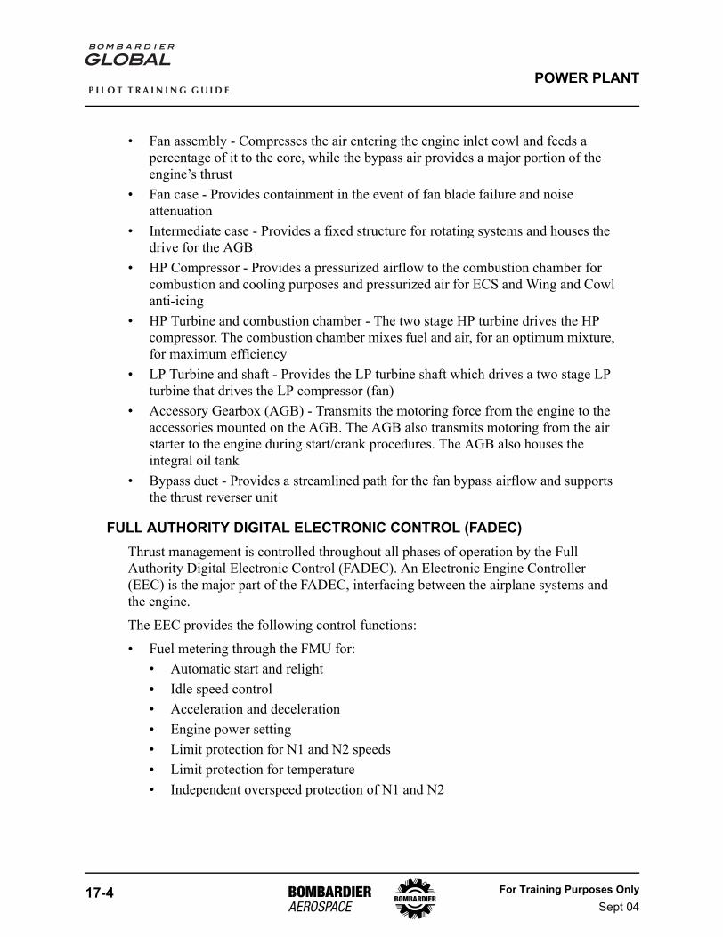
• Compressor airflow control via the and HP compressor bleed valves, to ensure:• Surge free acceleration and deceleration• Surge recovery• Stable operation
• Control of oil and fuel temperature• Control of the igniters and start air valve• Partial control of the thrust reverser system functions• Control of the engine power in reverse thrust• Control of system electrical supply, either 28 or dedicated generator output to the
EEC and through to the FADEC
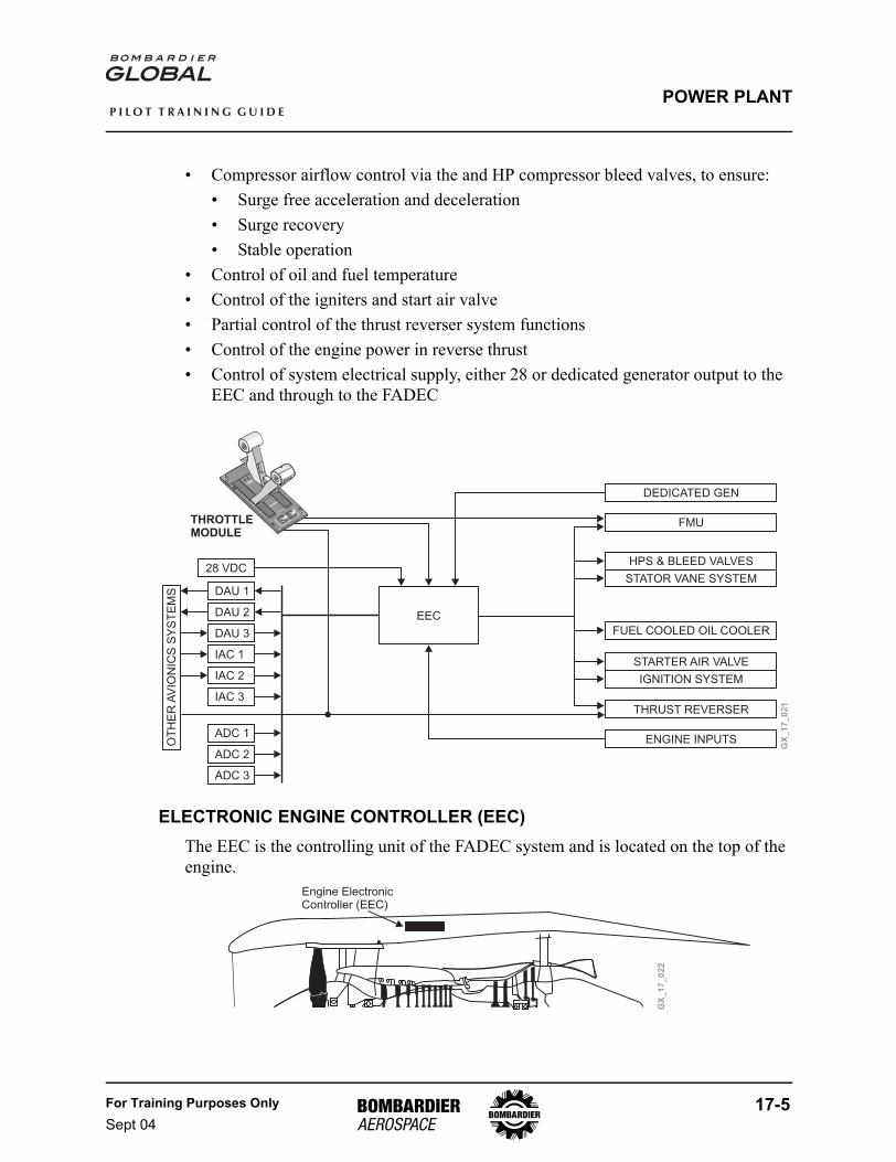
ELECTRONIC ENGINE CONTROLLER (EEC)The EEC is the controlling unit of the FADEC system and is located on the top of the engine.
GX
_1
7_
02
1
MAX
THRUST
IDLE
REV
MAX REV
ENG RUN R
L
THROTTLEMODULE
DAU 1
28 VDC
DAU 2
DAU 3
IAC 1
IAC 2
IAC 3
ADC 1
ADC 2
ADC 3
DEDICATED GEN
THRUST REVERSER
FMU
FUEL COOLED OIL COOLER
HPS & BLEED VALVES
STARTER AIR VALVE
STATOR VANE SYSTEM
IGNITION SYSTEM
OT
HE
RA
VIO
NIC
SS
YS
TE
MS
EEC
ENGINE INPUTS
GX
_1
7_
02
2
Engine ElectronicController (EEC)
17-6 For Training Purposes OnlySept 04
P I L O T T R A I N I N G G U I D E
POWER PLANT
The EEC is an electronic control unit containing two channels A and B. Each channel is comprised of a Central Processor Unit (CPU), Power Supply Unit (PSU) and an Independent Overspeed Protection (IOP) unit.
The PSU controls the power supplies to the FADEC system and to the EECs, CPU and IOP.
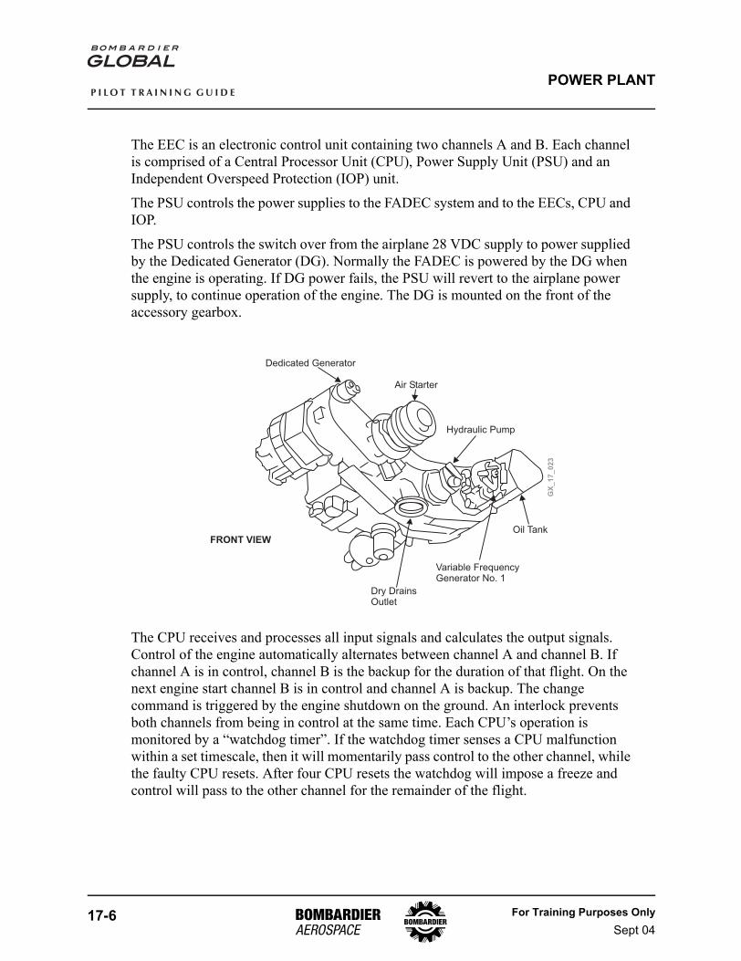
The PSU controls the switch over from the airplane 28 VDC supply to power supplied by the Dedicated Generator (DG). Normally the FADEC is powered by the DG when the engine is operating. If DG power fails, the PSU will revert to the airplane power supply, to continue operation of the engine. The DG is mounted on the front of the accessory gearbox.
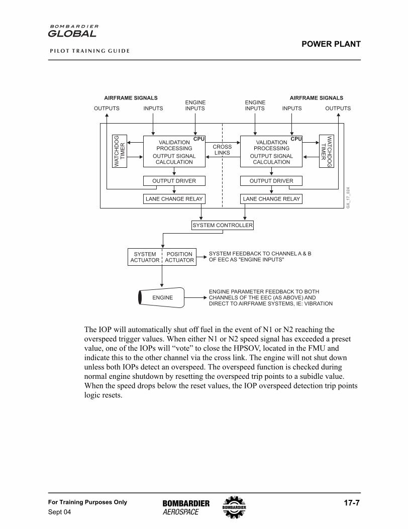
The CPU receives and processes all input signals and calculates the output signals. Control of the engine automatically alternates between channel A and channel B. If channel A is in control, channel B is the backup for the duration of that flight. On the next engine start channel B is in control and channel A is backup. The change command is triggered by the engine shutdown on the ground. An interlock prevents both channels from being in control at the same time. Each CPU’s operation is monitored by a “watchdog timer”. If the watchdog timer senses a CPU malfunction within a set timescale, then it will momentarily pass control to the other channel, while the faulty CPU resets. After four CPU resets the watchdog will impose a freeze and control will pass to the other channel for the remainder of the flight.
GX
_1
7_
02
3
Dedicated Generator
Air Starter
Hydraulic Pump
Oil Tank
Variable FrequencyGenerator No. 1
Dry DrainsOutlet
FRONT VIEW
For Training Purposes OnlySept 04
17-7
P I L O T T R A I N I N G G U I D E
POWER PLANT
The IOP will automatically shut off fuel in the event of N1 or N2 reaching the overspeed trigger values. When either N1 or N2 speed signal has exceeded a preset value, one of the IOPs will “vote” to close the HPSOV, located in the FMU and indicate this to the other channel via the cross link. The engine will not shut down unless both IOPs detect an overspeed. The overspeed function is checked during normal engine shutdown by resetting the overspeed trip points to a subidle value. When the speed drops below the reset values, the IOP overspeed detection trip points logic resets.
GX
_1
7_
02
4
AIRFRAME SIGNALS AIRFRAME SIGNALS
VALIDATIONPROCESSING
VALIDATIONPROCESSING
OUTPUT SIGNALCALCULATION
OUTPUT SIGNALCALCULATION
CPU CPU
OUTPUT DRIVER OUTPUT DRIVER
LANE CHANGE RELAY LANE CHANGE RELAY
WA
TC
HD
OG
TIM
ER
WA
TC
HD
OG
TIM
ER
SYSTEM CONTROLLER
SYSTEMACTUATOR
POSITIONACTUATOR
ENGINE
OUTPUTS OUTPUTSINPUTS INPUTSENGINEINPUTS
ENGINEINPUTS
CROSSLINKS
SYSTEM FEEDBACK TO CHANNEL A & BOF EEC AS "ENGINE INPUTS"
ENGINE PARAMETER FEEDBACK TO BOTHCHANNELS OF THE EEC (AS ABOVE) ANDDIRECT TO AIRFRAME SYSTEMS, IE: VIBRATION
17-8 For Training Purposes OnlySept 04
P I L O T T R A I N I N G G U I D E
POWER PLANT
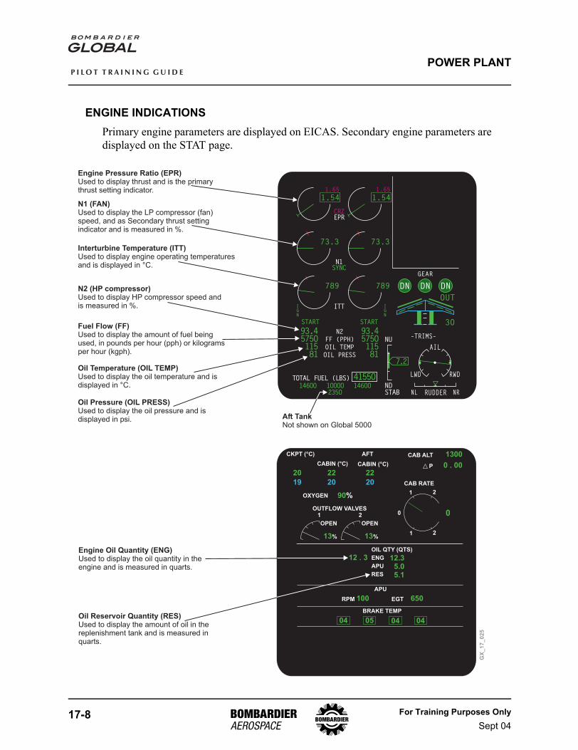
ENGINE INDICATIONSPrimary engine parameters are displayed on EICAS. Secondary engine parameters are displayed on the STAT page.
L ENG FLAMEOUTFUEL LO QTYFUEL IMBALANCEYD OFF
GLD MANUAL ARMPARK/EMER BRAKE ON
<– FUEL XFER ON
TOTAL FUEL (LBS) 4155O146OO 146OO1OOOO
N2
FF (PPH)
OIL TEMP
OIL PRESS
93.4575O11581
IGN
START START
IGN
NDSTAB
ITTSYNC
DN DN DN
OUT
3O
GEAR
–TRIMS–
NL NRRUDDER
AIL
RWDLWD
7.2
NU
93.4575O11581
235O
73.3
T/ON1SYNC
73.3
98.5 98.5
1.54
1.65
CRZEPR
1.54
1.65
789 789
GX
_1
7_
02
5
APU
RPM EGT
BRAKE TEMP
650100
0504 04 04
OIL QTY (QTS)
ENG
APU
RES
12 . 3 12.35.05.1
Engine Pressure Ratio (EPR)Used to display thrust and is the primarythrust setting indicator.
N1 (FAN)Used to display the LP compressor (fan)speed, and as Secondary thrust settingindicator and is measured in %.
Interturbine Temperature (ITT)Used to display engine operating temperaturesand is displayed in °C.
N2 (HP compressor)Used to display HP compressor speed andis measured in %.
Oil Temperature (OIL TEMP)Used to display the oil temperature and isdisplayed in °C.
Oil Pressure (OIL PRESS)Used to display the oil pressure and isdisplayed in psi.
Engine Oil Quantity (ENG)Used to display the oil quantity in theengine and is measured in quarts.
Oil Reservoir Quantity (RES)Used to display the amount of oil in thereplenishment tank and is measured inquarts.
Fuel Flow (FF)Used to display the amount of fuel beingused, in pounds per hour (pph) or kilogramsper hour (kgph).
Aft TankNot shown on Global 5000
1300
90%
13% 13%
0 . 0020
19 20
22 22
20
CABIN (°C) CABIN (°C)
OXYGEN
AFTCKPT (°C)
OPEN OPEN
OUTFLOW VALVES
CAB ALT
CAB RATE
P
00
1 2
1 2
1 2
For Training Purposes OnlySept 04
17-9
P I L O T T R A I N I N G G U I D E
POWER PLANT
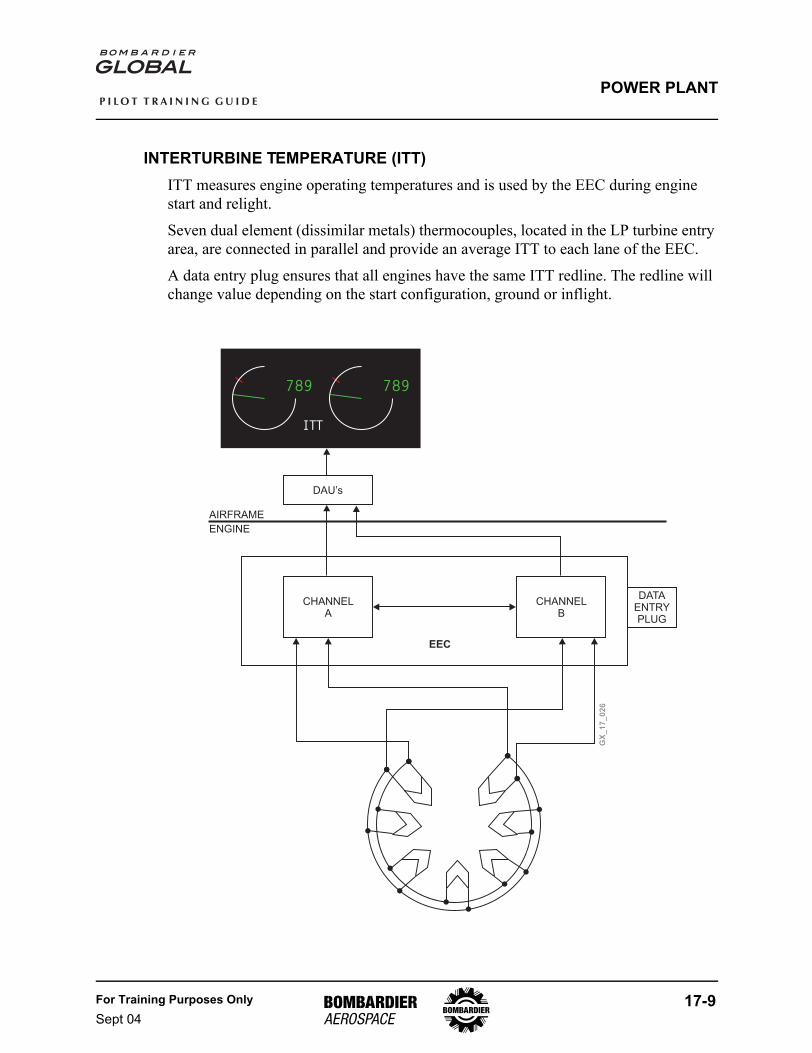
INTERTURBINE TEMPERATURE (ITT)ITT measures engine operating temperatures and is used by the EEC during engine start and relight.
Seven dual element (dissimilar metals) thermocouples, located in the LP turbine entry area, are connected in parallel and provide an average ITT to each lane of the EEC.
A data entry plug ensures that all engines have the same ITT redline. The redline will change value depending on the start configuration, ground or inflight.
789
ITT
789
GX
_1
7_
02
6CHANNEL
ACHANNEL
B
EEC
DAU’s
DATAENTRYPLUG
AIRFRAME
ENGINE
17-10 For Training Purposes OnlySept 04
P I L O T T R A I N I N G G U I D E
POWER PLANT
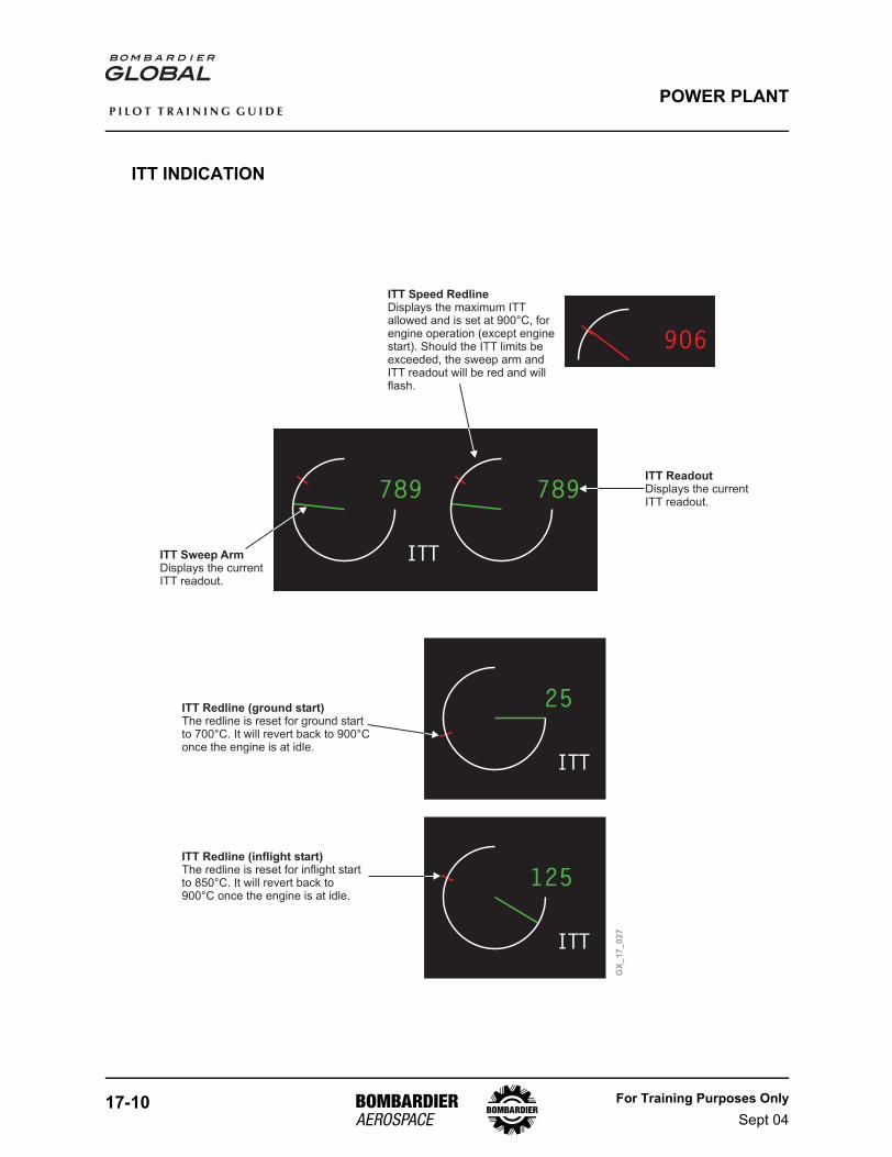
ITT INDICATION
789
ITT
789
25
ITT
125
ITT
GX
_1
7_
02
7
ITT Sweep ArmDisplays the currentITT readout.
ITT Speed RedlineDisplays the maximum ITTallowed and is set at 900°C, forengine operation (except enginestart). Should the ITT limits beexceeded, the sweep arm andITT readout will be red and willflash.
ITT ReadoutDisplays the currentITT readout.
ITT Redline (ground start)The redline is reset for ground startto 700°C. It will revert back to 900°Conce the engine is at idle.
ITT Redline (inflight start)The redline is reset for inflight startto 850°C. It will revert back to900°C once the engine is at idle.
9O6
For Training Purposes OnlySept 04
17-11
P I L O T T R A I N I N G G U I D E
POWER PLANT
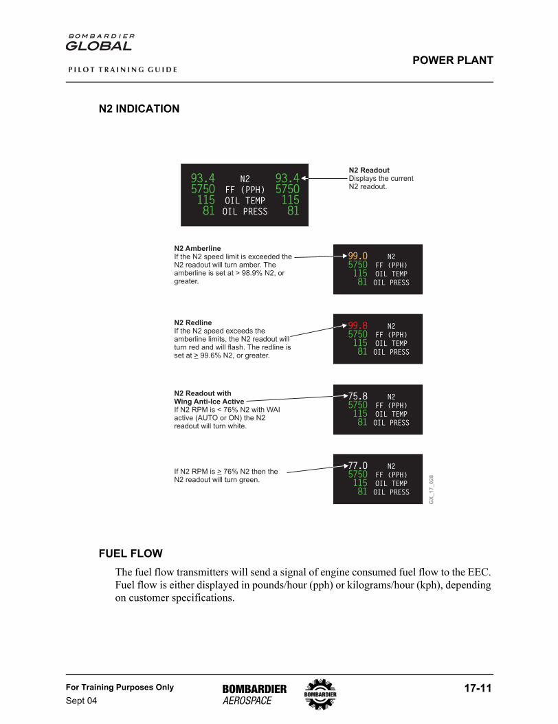
N2 INDICATION
FUEL FLOWThe fuel flow transmitters will send a signal of engine consumed fuel flow to the EEC. Fuel flow is either displayed in pounds/hour (pph) or kilograms/hour (kph), depending on customer specifications.
N2
FF (PPH)
OIL TEMP
OIL PRESS
77.O575O11581
N2
FF (PPH)
OIL TEMP
OIL PRESS
75.8575O11581
N2
FF (PPH)
OIL TEMP
OIL PRESS
99.8575O11581
N2
FF (PPH)
OIL TEMP
OIL PRESS
99.O575O11581
N2
FF (PPH)
OIL TEMP
OIL PRESS
93.4575O11581
93.4575O11581
N2 ReadoutDisplays the currentN2 readout.
N2 AmberlineIf the N2 speed limit is exceeded theN2 readout will turn amber. Theamberline is set at > 98.9% N2, orgreater.
N2 RedlineIf the N2 speed exceeds theamberline limits, the N2 readout willturn red and will flash. The redline isset at 99.6% N2> , or greater.
N2 Readout withWing Anti-Ice ActiveIf N2 RPM is < 76% N2 with WAIactive (AUTO or ON) the N2readout will turn white.
If N2 RPM is 76% N2 then theN2 readout will turn green.
>
GX
_1
7_
02
8
17-12 For Training Purposes OnlySept 04
P I L O T T R A I N I N G G U I D E
POWER PLANT
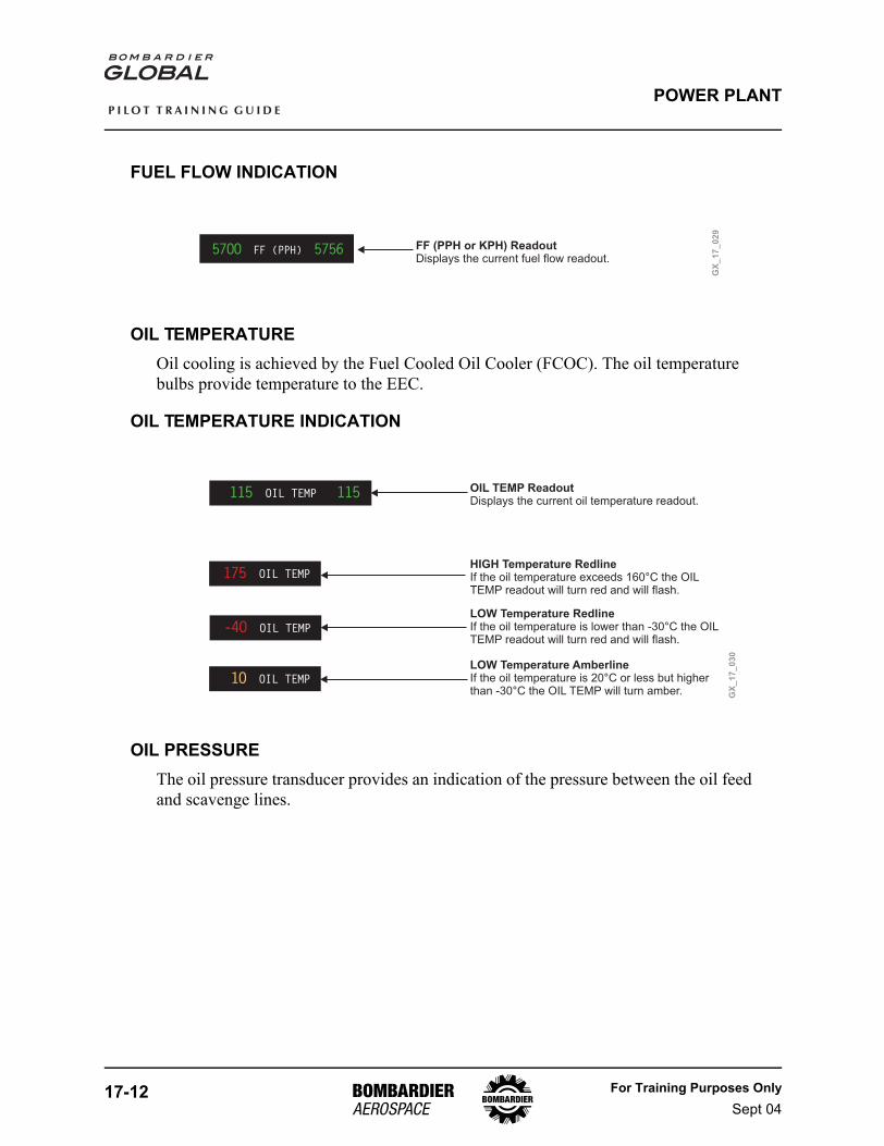
FUEL FLOW INDICATION
OIL TEMPERATUREOil cooling is achieved by the Fuel Cooled Oil Cooler (FCOC). The oil temperature bulbs provide temperature to the EEC.
OIL TEMPERATURE INDICATION
OIL PRESSUREThe oil pressure transducer provides an indication of the pressure between the oil feed and scavenge lines.
FF (PPH) 575657OO
GX
_1
7_
02
9
FF (PPH or KPH) ReadoutDisplays the current fuel flow readout.
OIL TEMP175
OIL TEMP 115115
OIL TEMP-4O
OIL TEMP1O
GX
_1
7_
03
0
OIL TEMP ReadoutDisplays the current oil temperature readout.
HIGH Temperature RedlineIf the oil temperature exceeds 160°C the OILTEMP readout will turn red and will flash.
LOW Temperature RedlineIf the oil temperature is lower than -30°C the OILTEMP readout will turn red and will flash.
LOW Temperature AmberlineIf the oil temperature is 20°C or less but higherthan -30°C the OIL TEMP will turn amber.
For Training Purposes OnlySept 04
17-13
P I L O T T R A I N I N G G U I D E
POWER PLANT
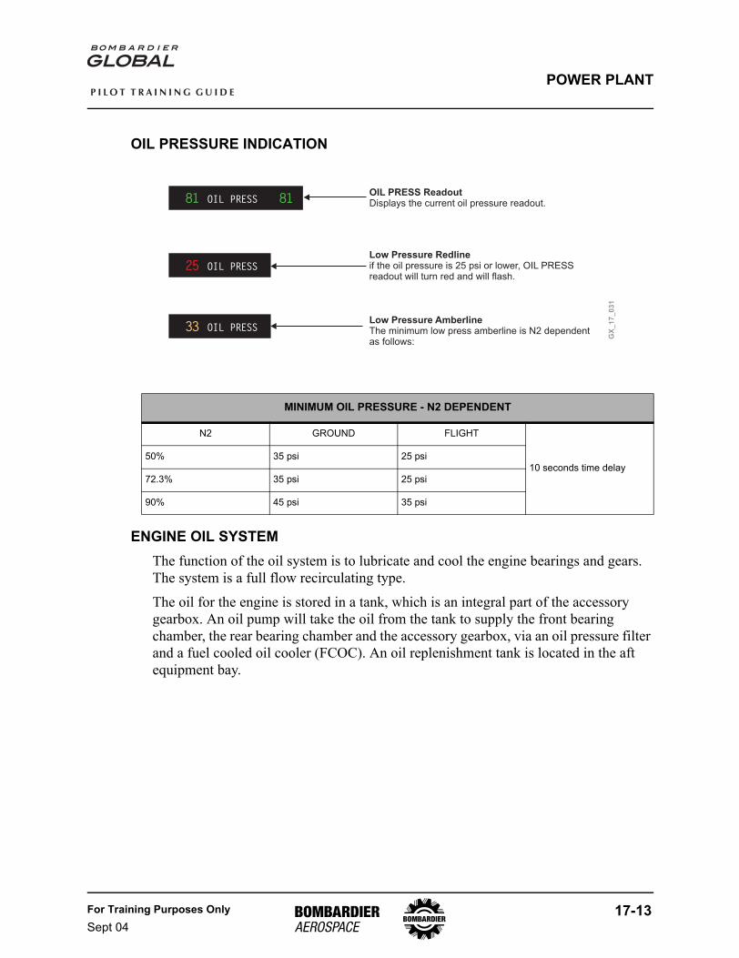
OIL PRESSURE INDICATION
ENGINE OIL SYSTEMThe function of the oil system is to lubricate and cool the engine bearings and gears. The system is a full flow recirculating type.
The oil for the engine is stored in a tank, which is an integral part of the accessory gearbox. An oil pump will take the oil from the tank to supply the front bearing chamber, the rear bearing chamber and the accessory gearbox, via an oil pressure filter and a fuel cooled oil cooler (FCOC). An oil replenishment tank is located in the aft equipment bay.
MINIMUM OIL PRESSURE - N2 DEPENDENT
N2 GROUND FLIGHT
10 seconds time delay50% 35 psi 25 psi
72.3% 35 psi 25 psi
90% 45 psi 35 psi
OIL PRESS 8181
OIL PRESS25
OIL PRESS33
GX
_1
7_
03
1
OIL PRESS ReadoutDisplays the current oil pressure readout.
Low Pressure Redlineif the oil pressure is 25 psi or lower, OIL PRESSreadout will turn red and will flash.
Low Pressure AmberlineThe minimum low press amberline is N2 dependentas follows:
17-14 For Training Purposes OnlySept 04
P I L O T T R A I N I N G G U I D E
POWER PLANT
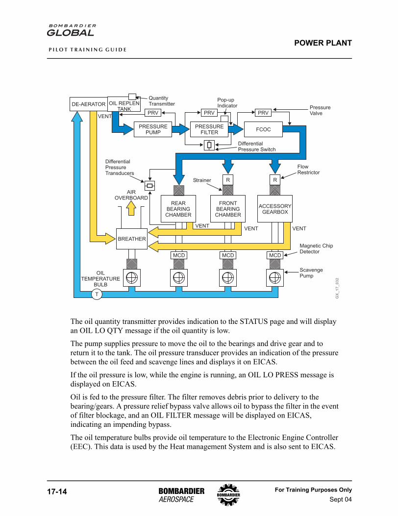
The oil quantity transmitter provides indication to the STATUS page and will display an OIL LO QTY message if the oil quantity is low.
The pump supplies pressure to move the oil to the bearings and drive gear and to return it to the tank. The oil pressure transducer provides an indication of the pressure between the oil feed and scavenge lines and displays it on EICAS.
If the oil pressure is low, while the engine is running, an OIL LO PRESS message is displayed on EICAS.
Oil is fed to the pressure filter. The filter removes debris prior to delivery to the bearing/gears. A pressure relief bypass valve allows oil to bypass the filter in the event of filter blockage, and an OIL FILTER message will be displayed on EICAS, indicating an impending bypass.
The oil temperature bulbs provide oil temperature to the Electronic Engine Controller (EEC). This data is used by the Heat management System and is also sent to EICAS.
GX
_1
7_
03
2
BREATHER
DE-AERATOR OIL REPLENTANK
R R
REARBEARINGCHAMBER
FRONTBEARINGCHAMBER
ACCESSORYGEARBOX
PRESSUREPUMP
PRESSUREFILTER
FCOC
PRV
MCD MCD
PRVPRV
AIROVERBOARD
MCD
T
DifferentialPressureTransducers
Strainer
FlowRestrictor
VENTVENT
VENT
VENT
DifferentialPressure Switch
PressureValve
Pop-upIndicator
QuantityTransmitter
Magnetic ChipDetector
ScavengePump
OILTEMPERATURE
BULB
For Training Purposes OnlySept 04
17-15
P I L O T T R A I N I N G G U I D E
POWER PLANT
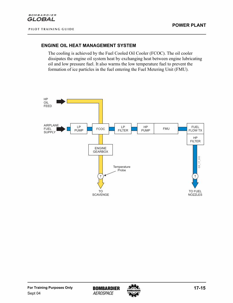
ENGINE OIL HEAT MANAGEMENT SYSTEMThe cooling is achieved by the Fuel Cooled Oil Cooler (FCOC). The oil cooler dissipates the engine oil system heat by exchanging heat between engine lubricating oil and low pressure fuel. It also warms the low temperature fuel to prevent the formation of ice particles in the fuel entering the Fuel Metering Unit (FMU).
GX
_1
7_
03
3
LPPUMP
FCOCLP
FILTERFUEL
FLOW TX
HPFILTER
HPPUMP
ENGINEGEARBOX
FMU
T T
TemperatureProbe
TOSCAVENGE
TO FUELNOZZLES
HPOILFEED
AIRPLANEFUELSUPPLY
17-16 For Training Purposes OnlySept 04
P I L O T T R A I N I N G G U I D E
POWER PLANT
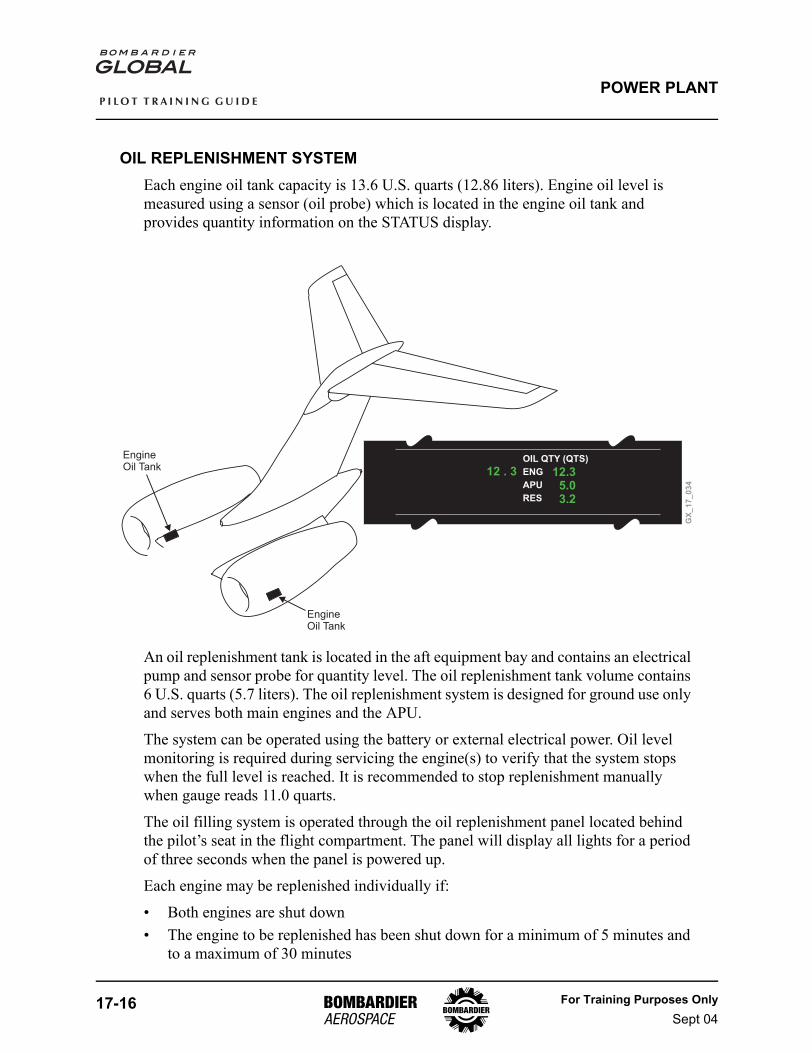
OIL REPLENISHMENT SYSTEMEach engine oil tank capacity is 13.6 U.S. quarts (12.86 liters). Engine oil level is measured using a sensor (oil probe) which is located in the engine oil tank and provides quantity information on the STATUS display.
An oil replenishment tank is located in the aft equipment bay and contains an electrical pump and sensor probe for quantity level. The oil replenishment tank volume contains 6 U.S. quarts (5.7 liters). The oil replenishment system is designed for ground use only and serves both main engines and the APU.
The system can be operated using the battery or external electrical power. Oil level monitoring is required during servicing the engine(s) to verify that the system stops when the full level is reached. It is recommended to stop replenishment manually when gauge reads 11.0 quarts.
The oil filling system is operated through the oil replenishment panel located behind the pilot’s seat in the flight compartment. The panel will display all lights for a period of three seconds when the panel is powered up.
Each engine may be replenished individually if:
• Both engines are shut down• The engine to be replenished has been shut down for a minimum of 5 minutes and
to a maximum of 30 minutes
GX
_1
7_
03
4
OIL QTY (QTS)
ENG
APU
RES
12 . 3 12.35.03.2
EngineOil Tank
EngineOil Tank
For Training Purposes OnlySept 04
17-17
P I L O T T R A I N I N G G U I D E
POWER PLANT
• To replenish the APU it has to have been shut down for a minimum of 15 minutes• The engine to be replenished is not already full• One of the other engines or APU is not currently being replenished• The aircraft has Weight on Wheels (WOW)
OIL REPLENISHMENT PANEL
OIL REPLENISHMENT
RESERVOIR
TANKLO
PUMPON
APU RH ENGLH ENG
POWER
SYSTEMON
LOOIL
LOOIL
LOOIL
VLVOPEN
VLVOPEN
VLVOPEN
GX
_1
7_
03
5
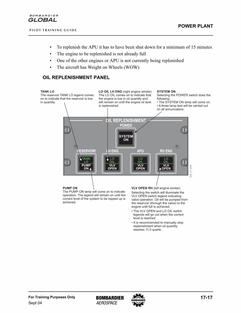
LO OIL LH ENG (right engine similar)The LO OIL comes on to indicate thatthe engine is low in oil quantity andwill remain on until the engine oil tankis replenished.
SYSTEM ONSelecting the POWER switch does thefollowing:• The SYSTEM ON lamp will come on.• A three lamp test will be carried outon all annunciators.
TANK LOThe reservoir TANK LO legend comeson to indicate that the reservoir is lowin quantity.
PUMP ONThe PUMP ON lamp will come on to indicateoperation. The legend will remain on until thecorrect level of the system to be topped up isachieved.
VLV OPEN RH (left engine similar)
Selecting the switch will illuminate theVLV OPEN switch legend indicatingvalve operation. Oil will be pumped fromthe reservoir (through the valve) to theengine until full is achieved.
• The VLV OPEN and LO OIL switchlegends will go out when the correctlevel is reached.
• It is recommended to manually stopreplenishment when oil quantityreaches 11.0 quarts.
17-18 For Training Purposes OnlySept 04
P I L O T T R A I N I N G G U I D E
POWER PLANT
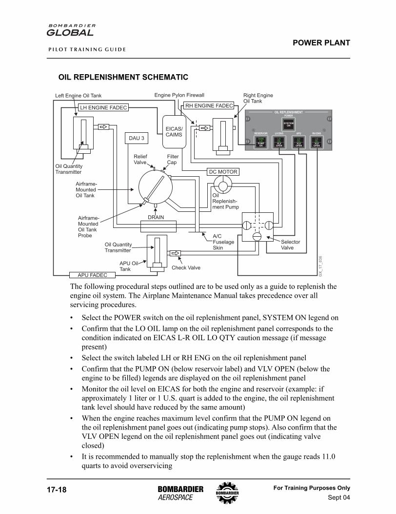
OIL REPLENISHMENT SCHEMATIC
The following procedural steps outlined are to be used only as a guide to replenish the engine oil system. The Airplane Maintenance Manual takes precedence over all servicing procedures.
• Select the POWER switch on the oil replenishment panel, SYSTEM ON legend on• Confirm that the LO OIL lamp on the oil replenishment panel corresponds to the
condition indicated on EICAS L-R OIL LO QTY caution message (if message present)
• Select the switch labeled LH or RH ENG on the oil replenishment panel• Confirm that the PUMP ON (below reservoir label) and VLV OPEN (below the
engine to be filled) legends are displayed on the oil replenishment panel• Monitor the oil level on EICAS for both the engine and reservoir (example: if
approximately 1 liter or 1 U.S. quart is added to the engine, the oil replenishment tank level should have reduced by the same amount)
• When the engine reaches maximum level confirm that the PUMP ON legend on the oil replenishment panel goes out (indicating pump stops). Also confirm that the VLV OPEN legend on the oil replenishment panel goes out (indicating valve closed)
• It is recommended to manually stop the replenishment when the gauge reads 11.0 quarts to avoid overservicing
OIL REPLENISHMENT
RESERVOIR
TANKLO
PUMPON
APU RH ENGLH ENG
POWER
SYSTEMON
LOOIL
LOOIL
LOOIL
VLVOPEN
VLVOPEN
VLVOPEN
GX
_1
7_
03
6
LH ENGINE FADEC RH ENGINE FADEC
APU FADEC
EICAS/CAIMS
DC MOTOR
DAU 3
Left Engine Oil Tank
Oil QuantityTransmitter
Airframe-MountedOil Tank
Airframe-MountedOil TankProbe
Oil QuantityTransmitter
APU OilTank Check Valve
DRAIN
A/CFuselageSkin
SelectorValve
Engine Pylon Firewall Right EngineOil Tank
OilReplenish-ment Pump
FilterCap
ReliefValve
For Training Purposes OnlySept 04
17-19
P I L O T T R A I N I N G G U I D E
POWER PLANT
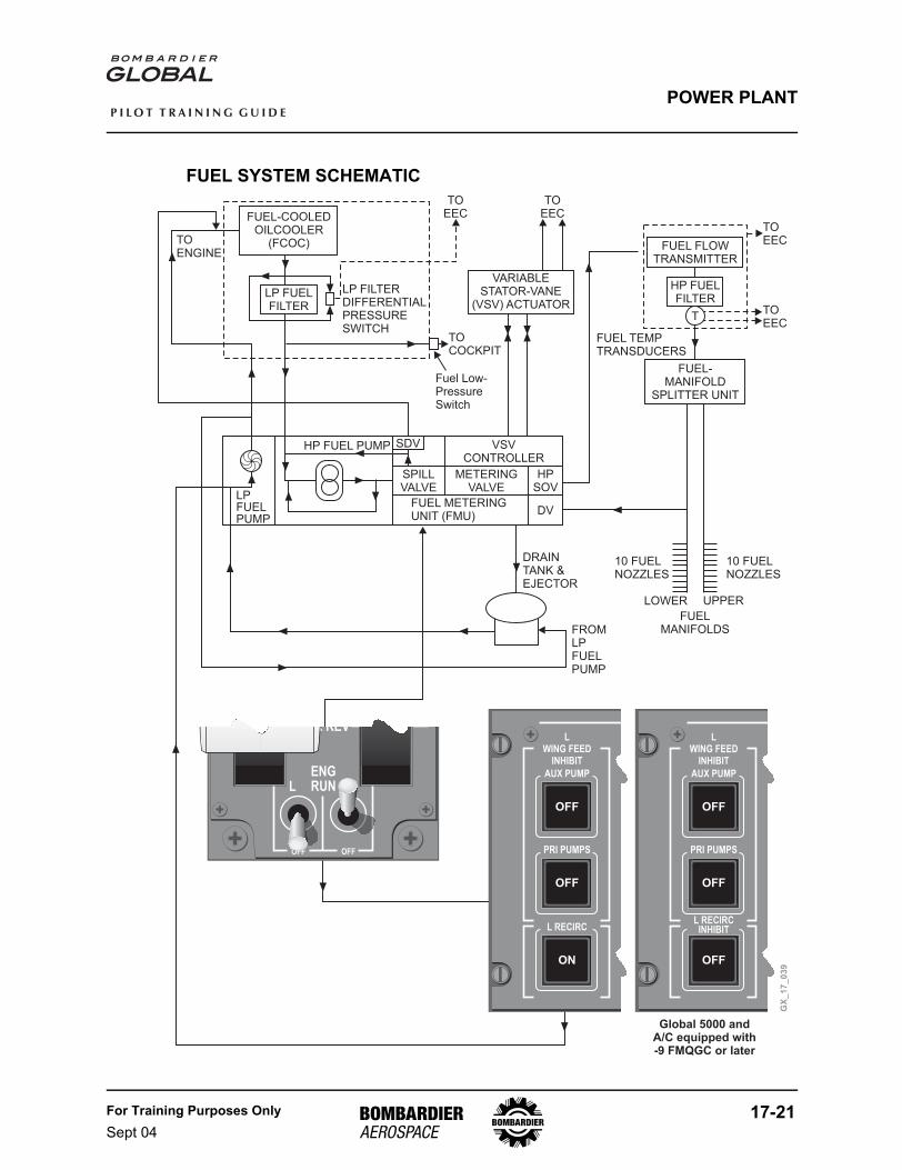
ENGINE FUEL SYSTEMThe fuel system provides engine fuel for combustion, HP compressor Variable Stator Vanes (VSV) actuation and engine oil cooling.
The main components that are contained in the fuel system are as follows:
• Fuel Pump Unit - The fuel pump unit contains both the LP and HP pumps. Fuel supplied from the airplane fuel system passes through the (centrifugal type) LP pump, is pressurized and is delivered to the Fuel Cooled Oil Cooler (FCOC)
• LP Filter - Fuel from the FCOC enters the LP fuel filter, where any debris is trapped before proceeding on to the HP pump. The fuel filter contains a combined DP switch/indicator. The combined unit provides indications on EICAS of low pressure fuel or an impending LP fuel filter blockage. A FUEL FILTER message will be displayed on EICAS. A fuel low pressure switch is also provided to alert the crew of low fuel pressure in the supply line to the HP pump. A FUEL LO PRESS message will be displayed on EICAS
• HP Fuel Pump - The HP fuel pump increases the pressure of the fuel for delivery to the Fuel Metering Unit (FMU)
• The FMU meters the fuel required by the engine in response to the Electronic Engine Controller (EEC) and provides pressure which is used as a motive force for the VSVs. The variable inlet guide vanes and the first three stages of stators of the HP compressor adjust the airflow entering the compressor to assist during engine starts, help prevent compressor surges and maintain best specific fuel consumption. The FMU also prevents fuel flowing to the fuel spray nozzles in the event of an engine overspeed, and drains the fuel manifold into the drain tank on engine shutdown. The desired fuel flow is maintained by controlling the position of the fuel metering valve. A constant pressure drop is maintained across the fuel metering valve by the spill valve, which diverts unused fuel back to the fuel pump. The spill diverter valve allows spill return fuel to the FCOC at low engine speeds to prevent fuel from recirculating around the HP pump, which could cause excessive fuel temperatures. The high pressure shutoff valve (HPSOV) allows the fuel to enter the HP fuel filter and is controlled by the FMU and the engine run switches
• Fuel Flow Transmitter - Provides an indication of fuel flow to the EEC and to EICAS
NOTECan be displayed in pounds/hour (pph) or kilograms/hour (kph).
GX
_1
7_
03
7
FF (PPH) 575O575O
17-20 For Training Purposes OnlySept 04
P I L O T T R A I N I N G G U I D E
POWER PLANT
• HP Filter - Prevents debris from entering the fuel manifold and causing possible blockage of the fuel spray nozzles
• Fuel Temperature Transducers - Fuel enters the fuel filter and passes over the temperature transducers which relay the information to the EEC for the heat management system and displays the temperature on the FUEL synoptic
• Overspeed and Splitter Unit (OSU) - Splits the fuel flow equally between the lower and upper fuel manifolds. In the event of LP shaft breakage detection, the OSU has a fuel shutoff mechanism that will open an overspeed valve to allow fuel pressure to close the splitter valve
• Fuel Spray Nozzles - Deliver the metered fuel into the combustion chamber. The combination of HP air and narrow fuel orifice in the nozzle causes the fuel to be forced into a fine spray for maximum efficiency combustion
• Fuel Drain Tank - The fuel is drained from the fuel manifold after engine shutdown and is passed through a drain valve in the FMU to the drain tank. The drain tank delivers the fuel to the LP pump during the next engine run. The tank has an integral injector which uses LP pump delivery fuel as a motive force to empty the tank
GX
_1
7_
03
8
32 °C
For Training Purposes OnlySept 04
17-21
P I L O T T R A I N I N G G U I D E
POWER PLANT
FUEL SYSTEM SCHEMATIC
GX
_1
7_
03
9
HP FUELFILTER
FUEL-MANIFOLD
SPLITTER UNIT
T
FUEL TEMPTRANSDUCERS
10 FUELNOZZLES
10 FUELNOZZLES
LOWER UPPER
FUELMANIFOLDS
TOEEC
TOEEC
VSVCONTROLLER
METERINGVALVE
HPSOV
DVFUEL METERINGUNIT (FMU)
SPILLVALVE
HP FUEL PUMP
LPFUELPUMP
FUEL FLOWTRANSMITTER
FUEL-COOLEDOILCOOLER
(FCOC)
LP FUELFILTER
LP FILTERDIFFERENTIALPRESSURESWITCH
SDV
TOENGINE
TOCOCKPIT
VARIABLESTATOR-VANE
(VSV) ACTUATOR
TOEEC
TOEEC
FROMLPFUELPUMP
DRAINTANK &EJECTOR
MAX REV
ENGRUN
OFF OFF
RL
Fuel Low-PressureSwitch
LWING FEED
INHIBIT
AUX PUMP
OFF
PRI PUMPS
OFF
L RECIRC
ON
LWING FEED
INHIBIT
AUX PUMP
OFF
PRI PUMPS
OFF
L RECIRCINHIBIT
OFF
Global 5000 andA/C equipped with-9 FMQGC or later
17-22 For Training Purposes OnlySept 04
P I L O T T R A I N I N G G U I D E
POWER PLANT
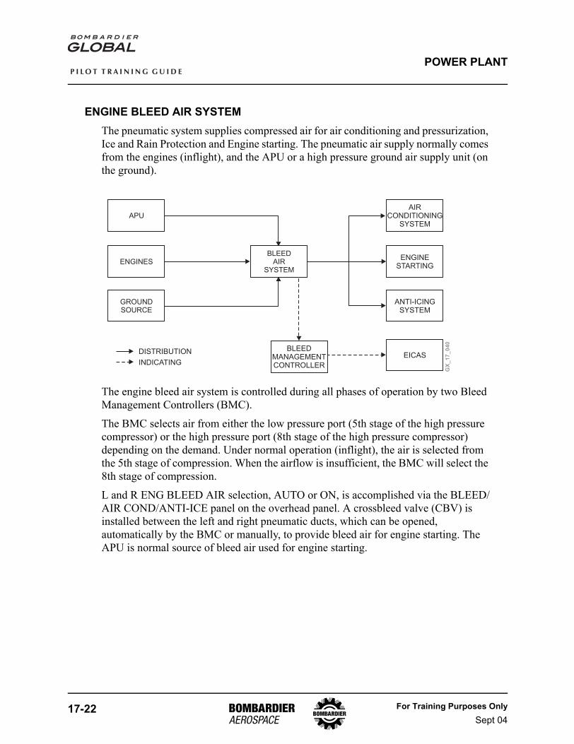
ENGINE BLEED AIR SYSTEMThe pneumatic system supplies compressed air for air conditioning and pressurization, Ice and Rain Protection and Engine starting. The pneumatic air supply normally comes from the engines (inflight), and the APU or a high pressure ground air supply unit (on the ground).
The engine bleed air system is controlled during all phases of operation by two Bleed Management Controllers (BMC).
The BMC selects air from either the low pressure port (5th stage of the high pressure compressor) or the high pressure port (8th stage of the high pressure compressor) depending on the demand. Under normal operation (inflight), the air is selected from the 5th stage of compression. When the airflow is insufficient, the BMC will select the 8th stage of compression.
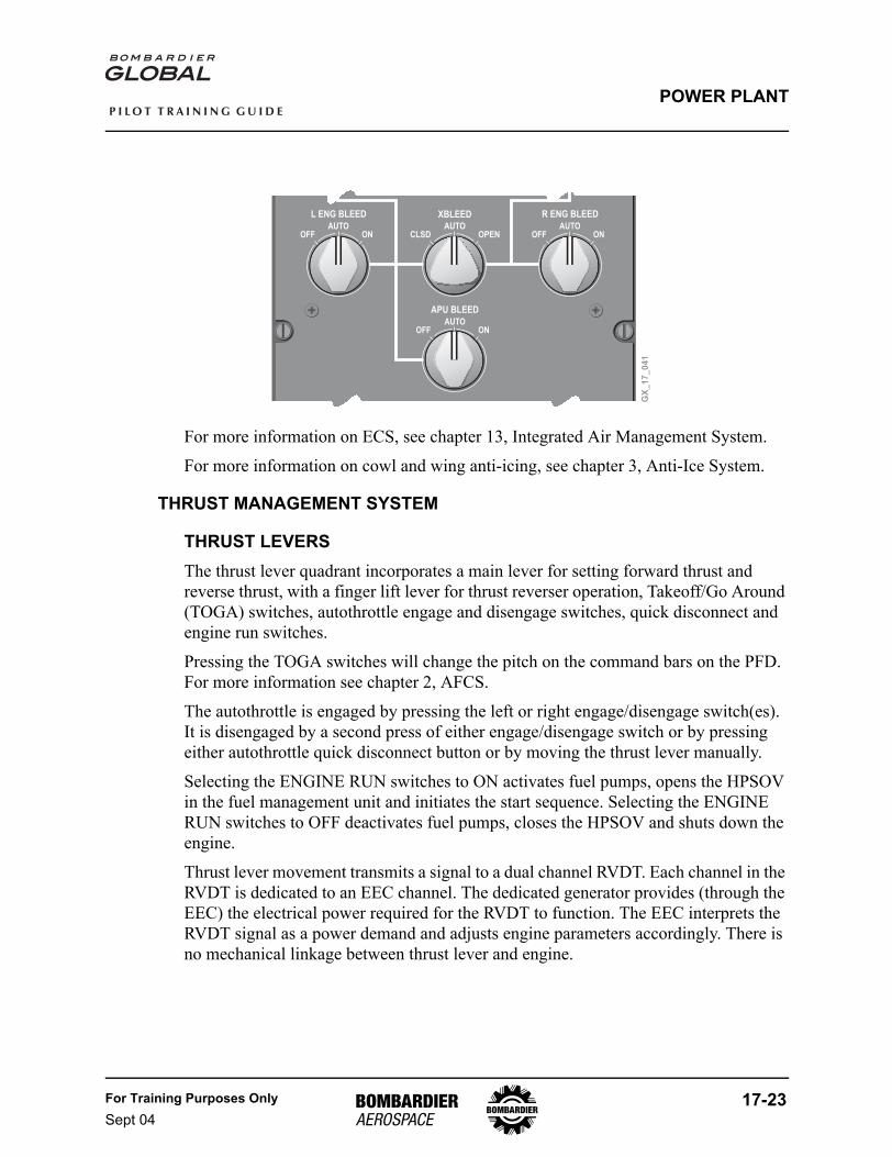
L and R ENG BLEED AIR selection, AUTO or ON, is accomplished via the BLEED/AIR COND/ANTI-ICE panel on the overhead panel. A crossbleed valve (CBV) is installed between the left and right pneumatic ducts, which can be opened, automatically by the BMC or manually, to provide bleed air for engine starting. The APU is normal source of bleed air used for engine starting.
GX
_1
7_
04
0
APU
ENGINES
GROUNDSOURCE
BLEEDMANAGEMENTCONTROLLER
AIRCONDITIONING
SYSTEM
ENGINESTARTING
ANTI-ICINGSYSTEM
EICASDISTRIBUTION
INDICATING
BLEEDAIR
SYSTEM
For Training Purposes OnlySept 04
17-23
P I L O T T R A I N I N G G U I D E
POWER PLANT
For more information on ECS, see chapter 13, Integrated Air Management System.
For more information on cowl and wing anti-icing, see chapter 3, Anti-Ice System.
THRUST MANAGEMENT SYSTEM
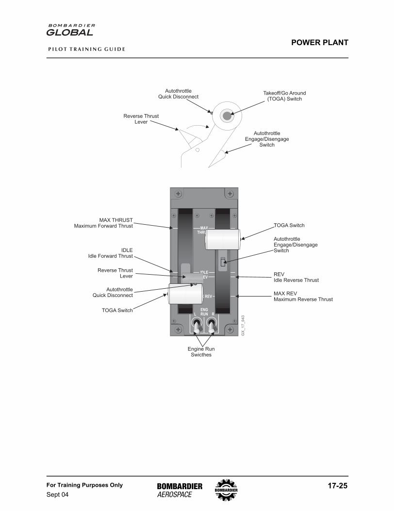
THRUST LEVERSThe thrust lever quadrant incorporates a main lever for setting forward thrust and reverse thrust, with a finger lift lever for thrust reverser operation, Takeoff/Go Around (TOGA) switches, autothrottle engage and disengage switches, quick disconnect and engine run switches.
Pressing the TOGA switches will change the pitch on the command bars on the PFD. For more information see chapter 2, AFCS.
The autothrottle is engaged by pressing the left or right engage/disengage switch(es). It is disengaged by a second press of either engage/disengage switch or by pressing either autothrottle quick disconnect button or by moving the thrust lever manually.
Selecting the ENGINE RUN switches to ON activates fuel pumps, opens the HPSOV in the fuel management unit and initiates the start sequence. Selecting the ENGINE RUN switches to OFF deactivates fuel pumps, closes the HPSOV and shuts down the engine.
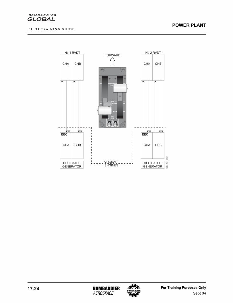
Thrust lever movement transmits a signal to a dual channel RVDT. Each channel in the RVDT is dedicated to an EEC channel. The dedicated generator provides (through the EEC) the electrical power required for the RVDT to function. The EEC interprets the RVDT signal as a power demand and adjusts engine parameters accordingly. There is no mechanical linkage between thrust lever and engine.
R ENG BLEEDL ENG BLEED
APU BLEED
AUTOCLSD OPEN
XBLEEDAUTO
OFF ONAUTO
OFF ON
AUTOOFF ON
GX
_1
7_
04
1
17-24 For Training Purposes OnlySept 04
P I L O T T R A I N I N G G U I D E
POWER PLANT
MAXTHRUST
IDLEREV
MAX REV
ENGRUN
OFF OFF
RL
DEDICATEDGENERATOR
DEDICATEDGENERATOR
CHA
CHA CHA
CHACHB
CHB
No 1 RVDT No 2 RVDT
CHB
CHB
EEC EEC
AIRCRAFTENGINES
FORWARD
GX
_1
7_
04
2
For Training Purposes OnlySept 04
17-25
P I L O T T R A I N I N G G U I D E
POWER PLANT
MAXTHRUST
IDLEREV
MAX REV
ENGRUN
OFF OFF
RL
GX
_1
7_
04
3
MAX THRUSTMaximum Forward Thrust
Reverse ThrustLever
AutothrottleQuick Disconnect
Takeoff/Go Around(TOGA) Switch
AutothrottleEngage/Disengage
Switch
TOGA Switch
AutothrottleEngage/DisengageSwitch
REVIdle Reverse Thrust
MAX REVMaximum Reverse Thrust
IDLEIdle Forward Thrust
Reverse ThrustLever
AutothrottleQuick Disconnect
TOGA Switch
Engine RunSwicthes
17-26 For Training Purposes OnlySept 04
P I L O T T R A I N I N G G U I D E
POWER PLANT
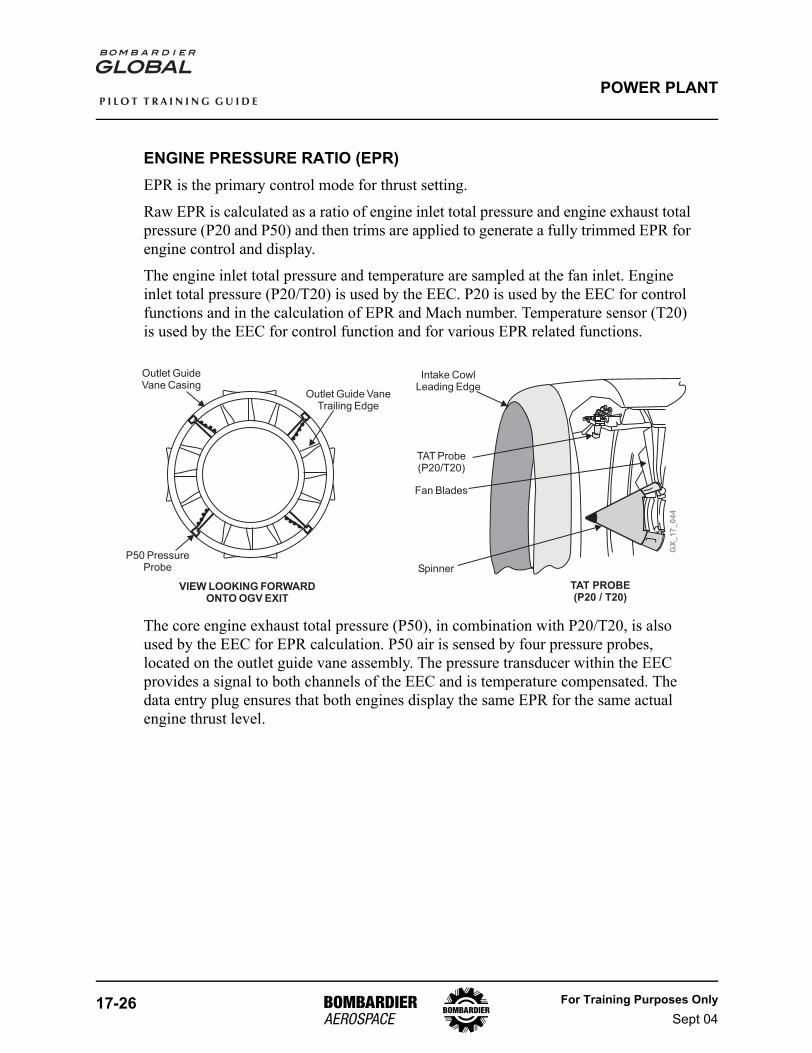
ENGINE PRESSURE RATIO (EPR)EPR is the primary control mode for thrust setting.
Raw EPR is calculated as a ratio of engine inlet total pressure and engine exhaust total pressure (P20 and P50) and then trims are applied to generate a fully trimmed EPR for engine control and display.
The engine inlet total pressure and temperature are sampled at the fan inlet. Engine inlet total pressure (P20/T20) is used by the EEC. P20 is used by the EEC for control functions and in the calculation of EPR and Mach number. Temperature sensor (T20) is used by the EEC for control function and for various EPR related functions.
The core engine exhaust total pressure (P50), in combination with P20/T20, is also used by the EEC for EPR calculation. P50 air is sensed by four pressure probes, located on the outlet guide vane assembly. The pressure transducer within the EEC provides a signal to both channels of the EEC and is temperature compensated. The data entry plug ensures that both engines display the same EPR for the same actual engine thrust level.
GX
_1
7_
04
4
Intake CowlLeading Edge
TAT Probe(P20/T20)
Spinner
Fan Blades
VIEW LOOKING FORWARDONTO OGV EXIT
Outlet GuideVane Casing
Outlet Guide VaneTrailing Edge
TAT PROBE(P20 / T20)
P50 PressureProbe
For Training Purposes OnlySept 04
17-27
P I L O T T R A I N I N G G U I D E
POWER PLANT
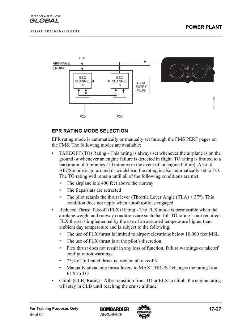
EPR RATING MODE SELECTIONEPR rating mode is automatically or manually set through the FMS PERF pages on the FMS. The following modes are available:
• TAKEOFF (TO) Rating - This rating is always set whenever the airplane is on the ground or whenever an engine failure is detected in flight. TO rating is limited to a maximum of 5 minutes (10 minutes in the event of an engine failure). Also, if AFCS mode is go-around or windshear, the rating is also automatically set to TO. The TO rating will remain until all of the following conditions are met:• The airplane is ≥ 400 feet above the runway• The flaps/slats are retracted• The pilot retards the thrust lever (Throttle Lever Angle (TLA) < 37°). This
condition does not apply when autothrottle is engaged• Reduced Thrust Takeoff (FLX) Rating - The FLX mode is permissible when the
airplane weight and runway conditions are such that full TO rating is not required. FLX thrust is implemented by the use of an assumed temperature higher than ambient day temperature and is subject to the following:• The use of FLX thrust is limited to airport elevations below 10,000 feet MSL• The use of FLX thrust is at the pilot’s discretion• Flex thrust does not result in any loss of function, failure warnings or takeoff
configuration warnings• 75% of full rated thrust is used on all takeoffs• Manually advancing thrust levers to MAX THRUST changes the rating from
FLX to TO• Climb (CLB) Rating - After transition from TO or FLX to climb, the engine rating
will stay in CLB until reaching the cruise altitude
GX
_1
7_
04
5
EECCHANNEL
A
EECCHANNEL
BDATA
ENTRYPLUG
P20 P50
1.54
1.65
CRZEPR
1.54
1.65AIRFRAME
ENGINE
P20
17-28 For Training Purposes OnlySept 04
P I L O T T R A I N I N G G U I D E
POWER PLANT
• After reaching initial cruise altitude, the rating will go back to CLB if a new climb is performed (step climb)
• Cruise (CRZ) Rating - This rating will transition from CLB to CRZ after reaching the Top Of Climb (TOC) altitude and the airplane speed has reached cruise speed target within 1 knot or 0.005 Mach
• The rating will remain in CRZ as the airplane descends, until flaps/slats or gear are selected down, at which point the rating will return to TO
• Maximum Continuous Thrust (MCT) - This rating is valid:• When an engine is failed, the rating mode will transition out of TO and into
MCT instead of CLB or CRZ• The rating will remain at MCT in the engine out condition, as long as the twin
engine rating would have been CLB or CRZ• Manual Engine Rating - Any rating (TO, CLB, MCT, CRZ) but FLEX can be
selected on the FMS RATING Select page. This freezes the rating type
For Training Purposes OnlySept 04
17-29
P I L O T T R A I N I N G G U I D E
POWER PLANT
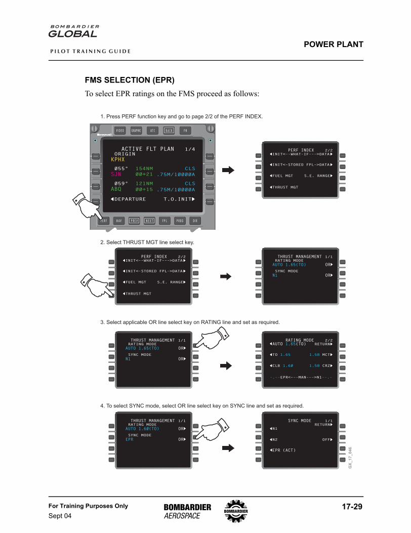
FMS SELECTION (EPR)To select EPR ratings on the FMS proceed as follows:
COMPARE FUEL QUANTITY0DEPARTURE T.O.INIT0
000ACTIVE FLT PLAN 1/4
0BOW PASS/@ LB0
0/170
0 00055° 154NM
15820 (00+21
00000001152ZKPHX
SJN
0 00059° 121NM
15820 (00+15 .75M/10000A
CLS
ABQ
0ORIGIN
.75M/10000A
CLS
123456789012345678901234
GX
_1
7_
04
6
1. Press PERF function key and go to page 2/2 of the PERF INDEX.
COMPARE FUEL QUANTITY0THRUST MGT T.O.INIT0
00OOOO0PERF INDEX 2/2
0BOW PASS/@ LB0
0/170
0INIT<–STORED FPL–>DATA
15820 (00+21
00000001152ZKPHX
SJN
0FUEL MGT
15820 (00+15 .75M/10000A
S.E. RANGEO
ABQ
0INIT<––WHAT–IF–––>DATA
.75M/10000A
COMPARE FUEL QUANTITY0THRUST MGT T.O.INIT0
00OOOO0PERF INDEX 2/2
0BOW PASS/@ LB0
0/170
0INIT<–STORED FPL–>DATA
15820 (00+21
00000001152ZKPHX
SJN
0FUEL MGT
15820 (00+15 .75M/10000A
S.E. RANGEO
ABQ
0INIT<––WHAT–IF–––>DATA
.75M/10000A
2. Select THRUST MGT line select key.
COMPARE FUEL QUANTITY0THRUST MGT T.O.INIT0
00 00000THRUST MANAGEMENT 1/1
0BOW
0/170
0 SYNC MODE
AUTO 1.65(TO)
N1
0FUEL MGT
15820 (00+15
S.E. RANGEO
ABQ
0 RATING MODE
ORS
ORO
ORO
COMPARE FUEL QUANTITY0THRUST MGT T.O.INIT0
00 00000THRUST MANAGEMENT 1/1
0BOW
0/170
0 SYNC MODE
AUTO 1.65(TO)
N1
0FUEL MGT
15820 (00+15
S.E. RANGEO
ABQ
0 RATING MODE
ORS
ORO
ORO
3. Select applicable OR line select key on RATING line and set as required.
COMPARE FUEL QUANTITYT.O.INIT0
00OOOORATING MODE 2/2
0AUTOBOW RETURN0
0/170
0TO 1.65
15820 (00+21
00000001152Z
OAUTO (TO)1.65
SJN
15820 (00+15 .75M/10000AABQ
.75M/10000A
1.58 MCTO
0CLB 1.60 1.58 CRZO
–.–– ––.–EPR<–––MAN–––>N1
COMPARE FUEL QUANTITY0THRUST MGT T.O.INIT0
00 00000THRUST MANAGEMENT 1/1
0BOW
0/170
0 SYNC MODE
AUTO 1.60(TO)
EPR
0FUEL MGT
15820 (00+15
S.E. RANGEO
ABQ
0 RATING MODE
ORS
ORO
ORO
4. To select SYNC mode, select OR line select key on SYNC line and set as required.
00OOOORSYNC MODE 1/1
RETURN0
0/1700N1
OEPR (ACT)
0N2 OFFO
17-30 For Training Purposes OnlySept 04
P I L O T T R A I N I N G G U I D E
POWER PLANT
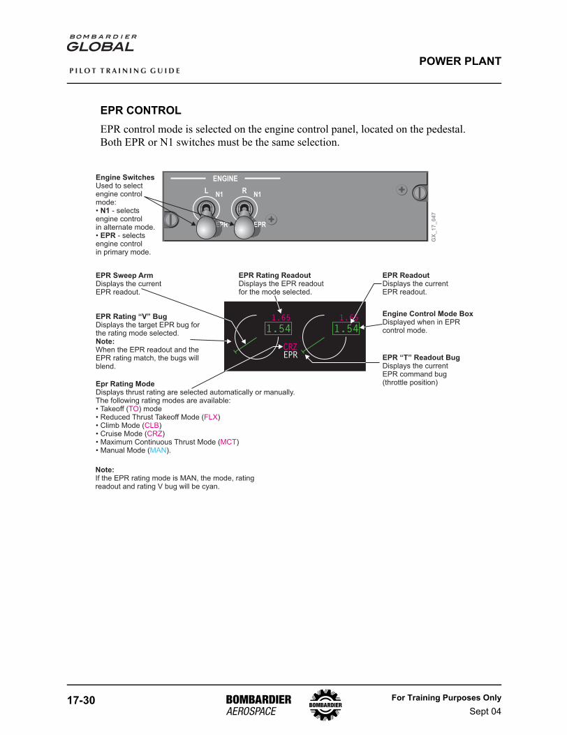
EPR CONTROLEPR control mode is selected on the engine control panel, located on the pedestal. Both EPR or N1 switches must be the same selection.
1.54
1.65
CRZEPR
1.54
1.65
ENGINE
RL
EPREPR
N1N1
EPR
GX
_1
7_
04
7
Engine Switches
N1
EPR
Used to selectengine controlmode:• - selectsengine controlin alternate mode.• - selectsengine controlin primary mode.
EPR Rating “V” Bug
Note:
Displays the target EPR bug forthe rating mode selected.
When the EPR readout and theEPR rating match, the bugs willblend.
Epr Rating ModeDisplays thrust rating are selected automatically or manually.The following rating modes are available:• Takeoff ( ) mode• Reduced Thrust Takeoff Mode ( )• Climb Mode ( )• Cruise Mode ( )• Maximum Continuous Thrust Mode ( )• Manual Mode ( ).
TO
CLBCRZ
MCT
FLX
MAN
EPR Rating ReadoutDisplays the EPR readoutfor the mode selected.
EPR ReadoutDisplays the currentEPR readout.
Engine Control Mode BoxDisplayed when in EPRcontrol mode.
EPR “T” Readout BugDisplays the currentEPR command bug(throttle position)
EPR Sweep ArmDisplays the currentEPR readout.
Note:If the EPR rating mode is MAN, the mode, ratingreadout and rating V bug will be cyan.
For Training Purposes OnlySept 04
17-31
P I L O T T R A I N I N G G U I D E
POWER PLANT
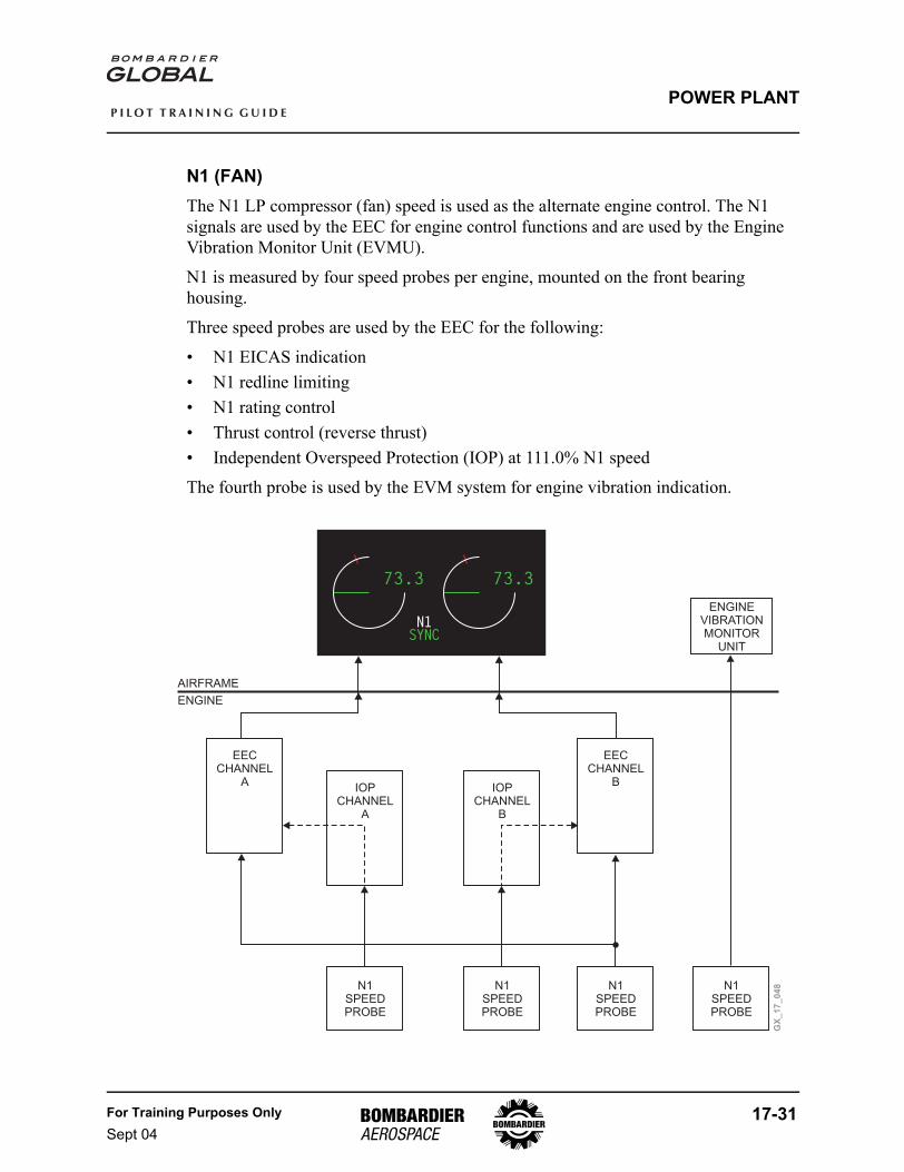
N1 (FAN)The N1 LP compressor (fan) speed is used as the alternate engine control. The N1 signals are used by the EEC for engine control functions and are used by the Engine Vibration Monitor Unit (EVMU).
N1 is measured by four speed probes per engine, mounted on the front bearing housing.
Three speed probes are used by the EEC for the following:
• N1 EICAS indication• N1 redline limiting• N1 rating control• Thrust control (reverse thrust)• Independent Overspeed Protection (IOP) at 111.0% N1 speed
The fourth probe is used by the EVM system for engine vibration indication.
73.3
T/ON1SYNC
73.3
GX
_1
7_
04
8
EECCHANNEL
AIOP
CHANNELA
IOPCHANNEL
B
EECCHANNEL
B
N1SPEEDPROBE
N1SPEEDPROBE
N1SPEEDPROBE
N1SPEEDPROBE
ENGINEVIBRATIONMONITOR
UNIT
AIRFRAME
ENGINE

17-32 For Training Purposes OnlySept 04
P I L O T T R A I N I N G G U I D E
POWER PLANT
N1 CONTROLN1 control mode is selected on the engine control panel, located on the pedestal. Both switches must be in the same position. N1 can also be selected automatically by the EEC in the event of an EPR control mode failure. A reversion done by EEC is known as a soft reversion. As per QRH, both switches should then be selected to N1. A manual reversion is known as a hard reversion. An amber EICAS message will be displayed when a failure is detected and a status message will be displayed, when the control switches have been selected to N1 control manually.
NOTEWhen the N1 readout and the N1 rating match, the bugs will blend.
73.3
T/ON1SYNC
73.3
98.5 98.5
L-R FADEC N1 CTL
GX
_1
7_
04
9
ENGINE
RL
EPREPR
N1N1
EPR
SoftReversion
N1 Rating ReadoutDisplays the N1 readoutfor MAN mode.
N1 Rating “V” BugDisplays the target N1bug for MAN mode.
N1 “T” Readout BugDisplays the currentN1 command bug.
N1 Sweep ArmDisplays the currentN1 readout.
N1 Speed RedlineDisplays the maximum N1 speedallowed and is set at 101.0%.Should the N1 limits beexceeded, the sweep arm andN1 readout will be red.
Engine Control Mode BoxDisplayed when in N1control mode.
N1 ReadoutDisplays the currentN1 readout.
N1 Rating ModeDisplays mode as selectedmanually via the FMSTHRUST MGT page.
NOTE:Before manually reverting to N1 control, the thrust leversshould be retarded to avoid thrust “bumps”.
SYNCDisplays synchronized mode asselected automatically by theautothrottle system or manualy viathe FMS. N1 is the default syncparameter.
For Training Purposes OnlySept 04
17-33
P I L O T T R A I N I N G G U I D E
POWER PLANT
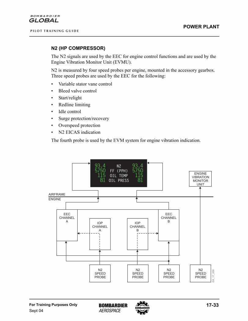
N2 (HP COMPRESSOR)The N2 signals are used by the EEC for engine control functions and are used by the Engine Vibration Monitor Unit (EVMU).
N2 is measured by four speed probes per engine, mounted in the accessory gearbox. Three speed probes are used by the EEC for the following:
• Variable stator vane control• Bleed valve control• Start/relight• Redline limiting• Idle control• Surge protection/recovery• Overspeed protection• N2 EICAS indication
The fourth probe is used by the EVM system for engine vibration indication.
N2
FF (PPH)
OIL TEMP
OIL PRESS
93.4575O11581
93.4575O11581
EECCHANNEL
AIOP
CHANNELA
IOPCHANNEL
B
EECCHANNEL
B
ENGINEVIBRATIONMONITOR
UNIT
AIRFRAME
ENGINE
GX
_1
7_
05
0N2SPEEDPROBE
N2SPEEDPROBE
N2SPEEDPROBE
N2SPEEDPROBE
17-34 For Training Purposes OnlySept 04
P I L O T T R A I N I N G G U I D E
POWER PLANT
ENGINE IDLE CONTROLThe EEC uses one of two modes to set steady state power above idle, EPR or N1 mode. Although idle is controlled to a RPM value, an equivalent EPR is also calculated so that the EEC can establish a Throttle RVDT Angle (TRA) to EPR relationship throughout the operating range.
The EEC will control idle to prevent the engine from operating below minimum limits to:
• Ensure that cabin bleed demands are met• Ensure cowl anti-ice demands are met on the ground or inflight• Ensure that the variable frequency generators stay on line• Protect against inclement weather by opening bleed valves to aid rejection of water
and maintain the surge margin, commanding continuous ignition to maintain combustion, as well as increasing engine speed by an appropriate margin
Low idle range is commanded when in the forward idle position and the airplane is not in an approach configuration.
High idle is commanded when in the forward idle position and the airplane is in an approach configuration.
If the EEC cannot determine whether or not an approach configuration has been set up, then the EEC will default to high idle.
Forward thrust is set by positioning the thrust levers manually or automatically. Reverse thrust is a manual selection only.
For Training Purposes OnlySept 04
17-35
P I L O T T R A I N I N G G U I D E
POWER PLANT
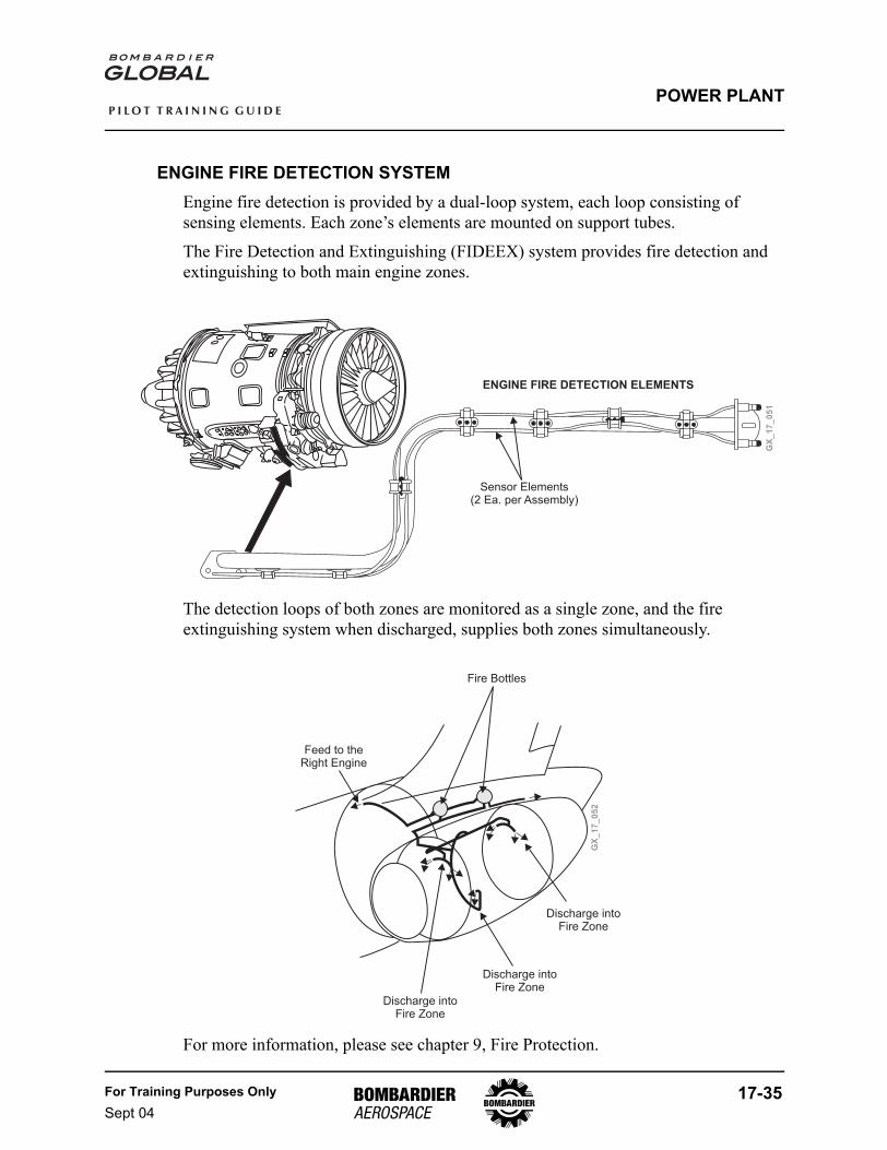
ENGINE FIRE DETECTION SYSTEMEngine fire detection is provided by a dual-loop system, each loop consisting of sensing elements. Each zone’s elements are mounted on support tubes.
The Fire Detection and Extinguishing (FIDEEX) system provides fire detection and extinguishing to both main engine zones.
The detection loops of both zones are monitored as a single zone, and the fire extinguishing system when discharged, supplies both zones simultaneously.
For more information, please see chapter 9, Fire Protection.
Sensor Elements(2 Ea. per Assembly)
ENGINE FIRE DETECTION ELEMENTS
GX
_1
7_
05
1
GX
_1
7_
05
2
Feed to theRight Engine
Discharge intoFire Zone
Fire Bottles
Discharge intoFire Zone
Discharge intoFire Zone
17-36 For Training Purposes OnlySept 04
P I L O T T R A I N I N G G U I D E
POWER PLANT
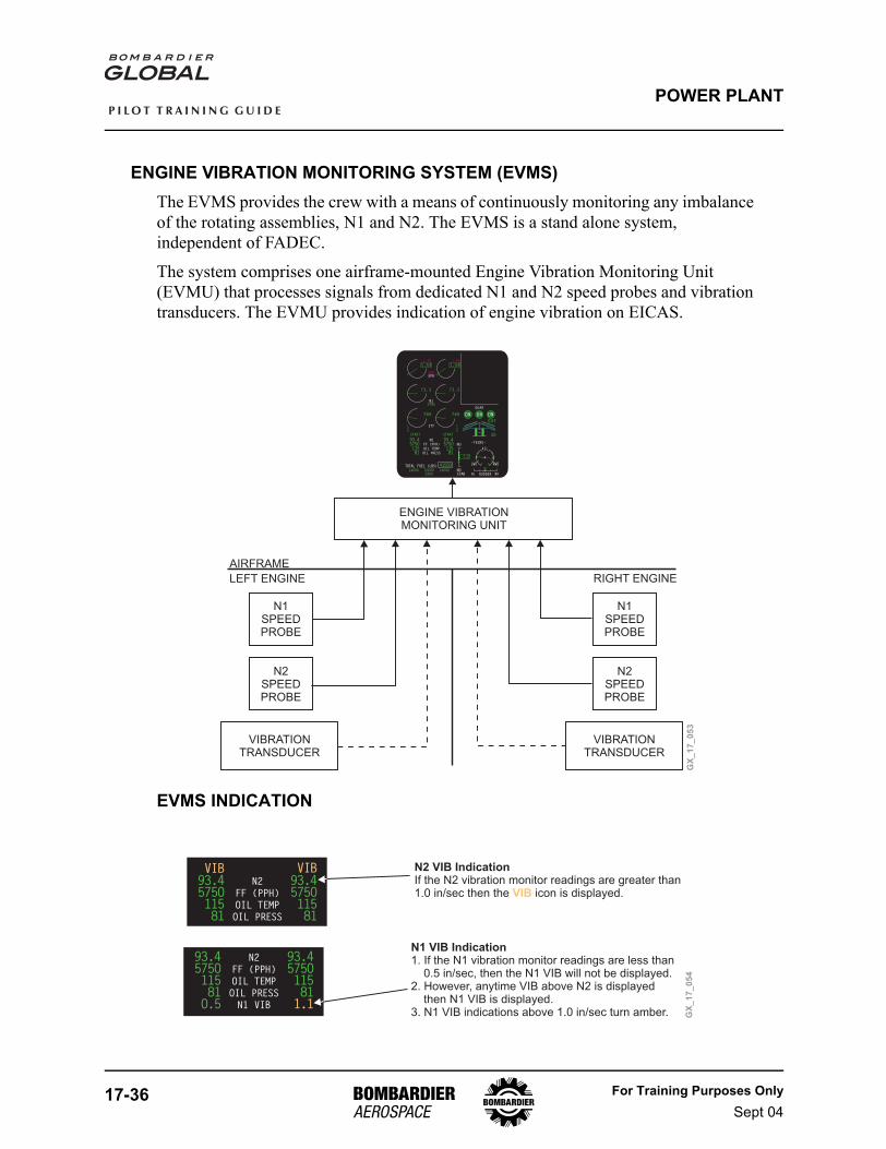
ENGINE VIBRATION MONITORING SYSTEM (EVMS)The EVMS provides the crew with a means of continuously monitoring any imbalance of the rotating assemblies, N1 and N2. The EVMS is a stand alone system, independent of FADEC.
The system comprises one airframe-mounted Engine Vibration Monitoring Unit (EVMU) that processes signals from dedicated N1 and N2 speed probes and vibration transducers. The EVMU provides indication of engine vibration on EICAS.
EVMS INDICATION
L ENG FLAMEOUTFUEL LO QTYFUEL IMBALANCEYD OFF
GLD MANUAL ARMPARK/EMER BRAKE ON
<– FUEL XFER ON
TOTAL FUEL (LBS) 4155O146OO 146OO1OOOO
N2
FF (PPH)
OIL TEMP
OIL PRESS
93.4575O11581
IGN
START START
IGN
NDSTAB
ITTSYNC
DN DN DN
OUT
3O
GEAR
–TRIMS–
NL NRRUDDER
AIL
RWDLWD
7.2
NU
93.4575O11581
235O
73.3
T/ON1SYNC
73.3
98.5 98.5
1.54
1.65
CRZEPR
1.54
1.65
789 789
GX
_1
7_
05
3
ENGINE VIBRATIONMONITORING UNIT
N1SPEEDPROBE
N1SPEEDPROBE
N2SPEEDPROBE
AIRFRAME
LEFT ENGINE RIGHT ENGINE
VIBRATIONTRANSDUCER
VIBRATIONTRANSDUCER
N2SPEEDPROBE
N2
FF (PPH)
OIL TEMP
OIL PRESS
93.4575O11581
93.4575O11581
VIB VIB
N2
FF (PPH)
OIL TEMP
OIL PRESS
N1 VIB
93.4575O115811.1
93.4575O11581O.5
GX
_1
7_
05
4
N2 VIB IndicationIf the N2 vibration monitor readings are greater than1.0 in/sec then the icon is displayed.VIB
N1 VIB Indication1. If the N1 vibration monitor readings are less than
0.5 in/sec, then the N1 VIB will not be displayed.2. However, anytime VIB above N2 is displayed
then N1 VIB is displayed.3. N1 VIB indications above 1.0 in/sec turn amber.
For Training Purposes OnlySept 04
17-37
P I L O T T R A I N I N G G U I D E
POWER PLANT
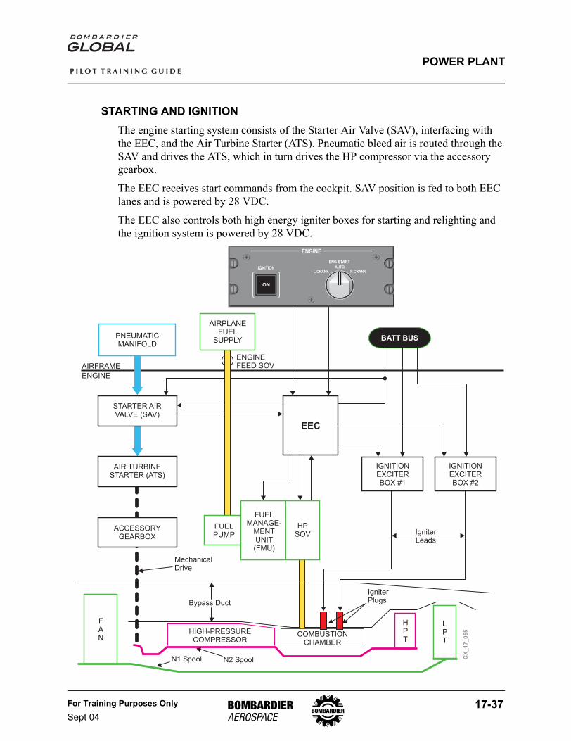
STARTING AND IGNITIONThe engine starting system consists of the Starter Air Valve (SAV), interfacing with the EEC, and the Air Turbine Starter (ATS). Pneumatic bleed air is routed through the SAV and drives the ATS, which in turn drives the HP compressor via the accessory gearbox.
The EEC receives start commands from the cockpit. SAV position is fed to both EEC lanes and is powered by 28 VDC.
The EEC also controls both high energy igniter boxes for starting and relighting and the ignition system is powered by 28 VDC.
GX
_1
7_
05
5
BATT BUSPNEUMATICMANIFOLD
AIRPLANEFUEL
SUPPLY
AIR TURBINESTARTER (ATS)
IGNITIONEXCITERBOX #1
IGNITIONEXCITERBOX #2
ACCESSORYGEARBOX
FUELPUMP
FUELPUMP
ENGINEFEED SOVAIRFRAME
ENGINE
STARTER AIRVALVE (SAV)
EEC
FUELMANAGE-
MENTUNIT(FMU)
HPSOV
LPT
HPT
COMBUSTIONCHAMBER
HIGH-PRESSURECOMPRESSOR
N2 SpoolN1 Spool
IgniterPlugs
MechanicalDrive
Bypass Duct
FAN
IgniterLeads
ENGINE
ENG START
IGNITION
ON
AUTOL CRANK R CRANK
17-38 For Training Purposes OnlySept 04
P I L O T T R A I N I N G G U I D E
POWER PLANT
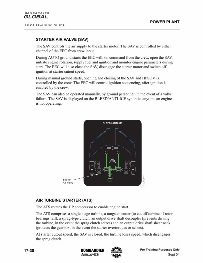
STARTER AIR VALVE (SAV)The SAV controls the air supply to the starter motor. The SAV is controlled by either channel of the EEC from crew input.
During AUTO ground starts the EEC will, on command from the crew, open the SAV, initiate engine rotation, supply fuel and ignition and monitor engine parameters during start. The EEC will also close the SAV, disengage the starter motor and switch off ignition at starter cutout speed.
During manual ground starts, opening and closing of the SAV and HPSOV is controlled by the crew. The EEC will control ignition sequencing, after ignition is enabled by the crew.
The SAV can also be operated manually, by ground personnel, in the event of a valve failure. The SAV is displayed on the BLEED/ANTI-ICE synoptic, anytime an engine is not operating.
AIR TURBINE STARTER (ATS)The ATS rotates the HP compressor to enable engine start.
The ATS comprises a single-stage turbine, a tungsten cutter (to cut off turbine, if rotor bearings fail), a sprag-type clutch, an output drive shaft decoupler (prevents driving the turbine, in the event the sprag clutch seizes) and an output drive shaft shear neck (protects the gearbox, in the event the starter overtorques or seizes).
At starter cutout speed, the SAV is closed, the turbine loses speed, which disengages the sprag clutch.
GX
_1
7_
05
6
BLEED / ANTI-ICE
APU
AIRCOND
L
40PSI
40PSI
R
LPLP
HP HP
StarterAir Valve
For Training Purposes OnlySept 04
17-39
P I L O T T R A I N I N G G U I D E
POWER PLANT
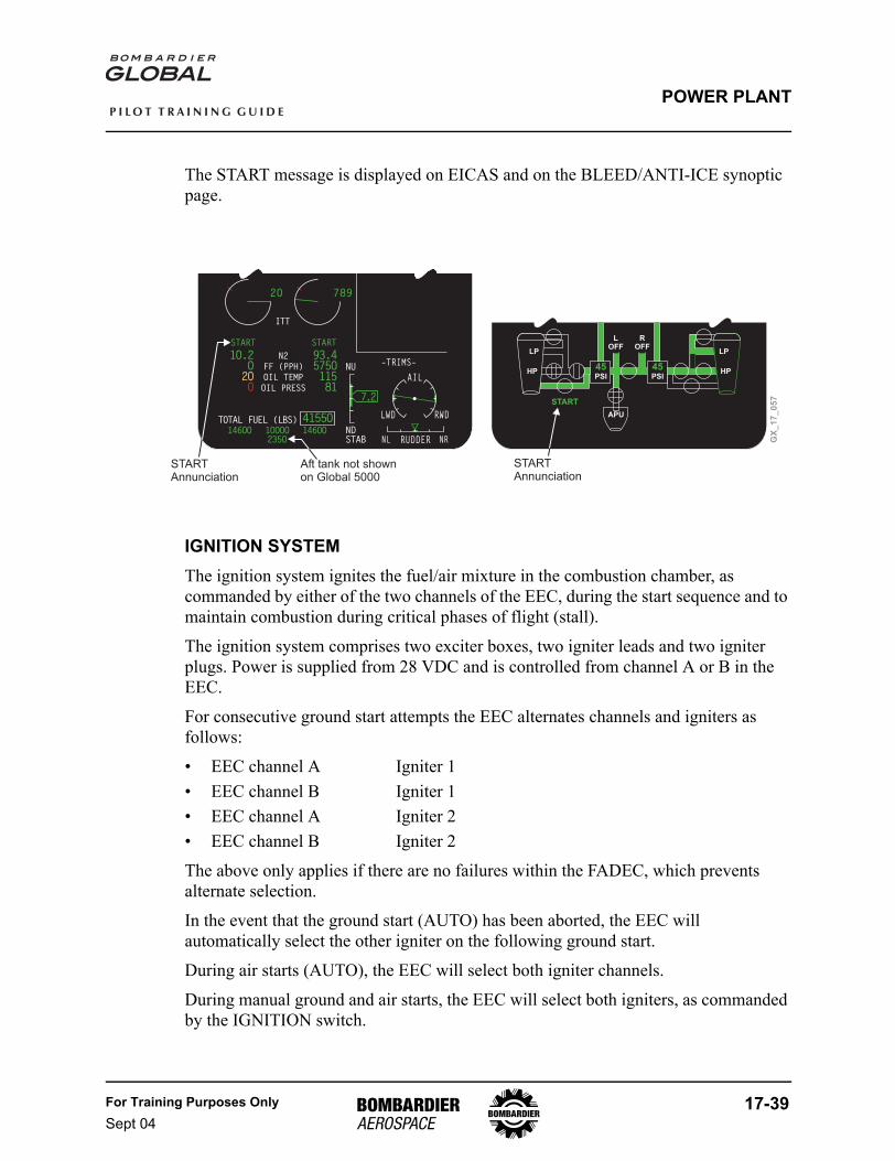
The START message is displayed on EICAS and on the BLEED/ANTI-ICE synoptic page.
IGNITION SYSTEMThe ignition system ignites the fuel/air mixture in the combustion chamber, as commanded by either of the two channels of the EEC, during the start sequence and to maintain combustion during critical phases of flight (stall).
The ignition system comprises two exciter boxes, two igniter leads and two igniter plugs. Power is supplied from 28 VDC and is controlled from channel A or B in the EEC.
For consecutive ground start attempts the EEC alternates channels and igniters as follows:
• EEC channel A Igniter 1• EEC channel B Igniter 1• EEC channel A Igniter 2• EEC channel B Igniter 2
The above only applies if there are no failures within the FADEC, which prevents alternate selection.
In the event that the ground start (AUTO) has been aborted, the EEC will automatically select the other igniter on the following ground start.
During air starts (AUTO), the EEC will select both igniter channels.
During manual ground and air starts, the EEC will select both igniters, as commanded by the IGNITION switch.
TOTAL FUEL (LBS) 4155O146OO 146OO1OOOO
N2
FF (PPH)
OIL TEMP
OIL PRESS
93.4575O11581
START START
NDSTAB
ITTSYNC
–TRIMS–
NL NRRUDDER
AIL
RWDLWD
7.2
NU
1O.2O2OO
235O
2O 789
GX
_1
7_
05
7
APU
LOFF
45PSI
45PSI
ROFF
LP
HP
LP
HP
START
STARTAnnunciation
STARTAnnunciation
Aft tank not shownon Global 5000
17-40 For Training Purposes OnlySept 04
P I L O T T R A I N I N G G U I D E
POWER PLANT
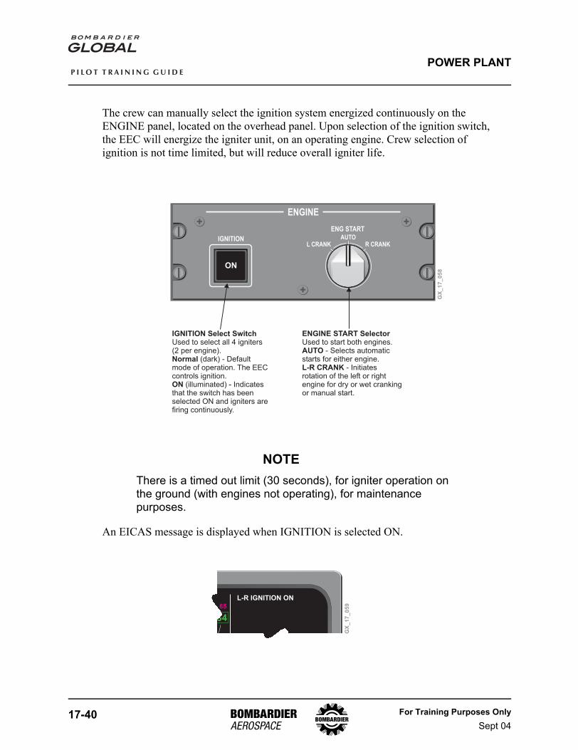
The crew can manually select the ignition system energized continuously on the ENGINE panel, located on the overhead panel. Upon selection of the ignition switch, the EEC will energize the igniter unit, on an operating engine. Crew selection of ignition is not time limited, but will reduce overall igniter life.
NOTEThere is a timed out limit (30 seconds), for igniter operation on the ground (with engines not operating), for maintenance purposes.
An EICAS message is displayed when IGNITION is selected ON.
ENGINE
ENG START
IGNITION
ON
AUTOL CRANK R CRANK
GX
_1
7_
05
8
IGNITION Select Switch
Normal
ON
Used to select all 4 igniters(2 per engine).
(dark) - Defaultmode of operation. The EECcontrols ignition.
(illuminated) - Indicatesthat the switch has beenselected ON and igniters arefiring continuously.
ENGINE START Selector
AUTO
L-R CRANK
Used to start both engines.- Selects automatic
starts for either engine.- Initiates
rotation of the left or rightengine for dry or wet crankingor manual start.
L-R IGNITION ON
GX
_1
7_
05
9
For Training Purposes OnlySept 04
17-41
P I L O T T R A I N I N G G U I D E
POWER PLANT
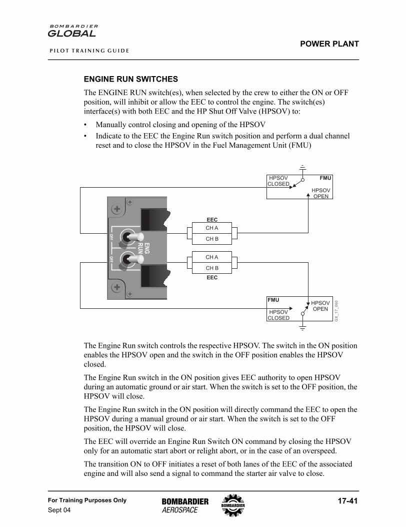
ENGINE RUN SWITCHESThe ENGINE RUN switch(es), when selected by the crew to either the ON or OFF position, will inhibit or allow the EEC to control the engine. The switch(es) interface(s) with both EEC and the HP Shut Off Valve (HPSOV) to:
• Manually control closing and opening of the HPSOV• Indicate to the EEC the Engine Run switch position and perform a dual channel
reset and to close the HPSOV in the Fuel Management Unit (FMU)
The Engine Run switch controls the respective HPSOV. The switch in the ON position enables the HPSOV open and the switch in the OFF position enables the HPSOV closed.
The Engine Run switch in the ON position gives EEC authority to open HPSOV during an automatic ground or air start. When the switch is set to the OFF position, the HPSOV will close.
The Engine Run switch in the ON position will directly command the EEC to open the HPSOV during a manual ground or air start. When the switch is set to the OFF position, the HPSOV will close.
The EEC will override an Engine Run Switch ON command by closing the HPSOV only for an automatic start abort or relight abort, or in the case of an overspeed.
The transition ON to OFF initiates a reset of both lanes of the EEC of the associated engine and will also send a signal to command the starter air valve to close.
GX
_1
7_
06
0
HPSOVCLOSED
HPSOVOPEN
FMU
HPSOVCLOSED
HPSOVOPEN
FMU
CH A
CH B
EEC
CH A
CH B
EEC
EN
GR
UN
OF
FO
FF R
L
17-42 For Training Purposes OnlySept 04
P I L O T T R A I N I N G G U I D E
POWER PLANT
ENGINE STARTING
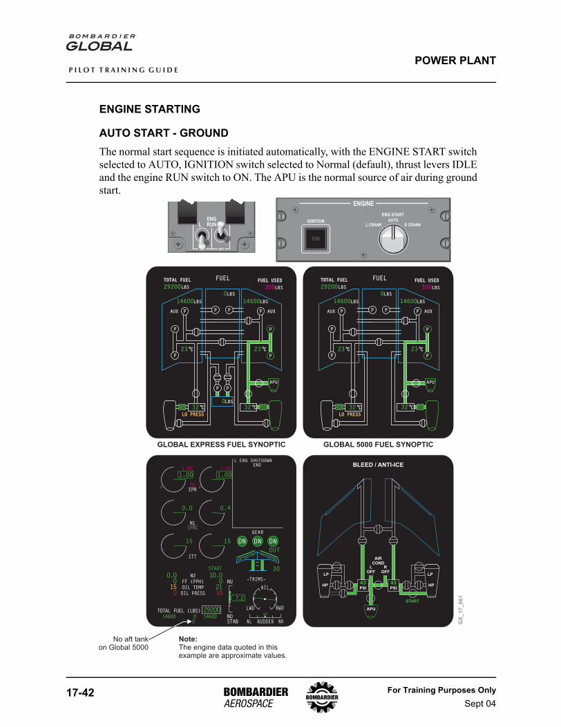
AUTO START - GROUNDThe normal start sequence is initiated automatically, with the ENGINE START switch selected to AUTO, IGNITION switch selected to Normal (default), thrust levers IDLE and the engine RUN switch to ON. The APU is the normal source of air during ground start.
TOTAL FUEL (LBS) 292OO146OO 146OOO
N2
FF (PPH)
OIL TEMP
OIL PRESS
1O.OO211O
START
NDSTAB
ITTSYNC
DN DN DN
OUT
3O
GEAR
–TRIMS–
NL NRRUDDER
AIL
RWDLWD
7.2
NU
O.OO15O
O
O.O
T/ON1SYNC
O.4
98.5 98.5
1.OO
1.55
TOEPR
1.OO
1.55
15 15
L ENG SHUTDOWNEND
PPP
P
P P
P
P
FUEL
AUX
23°C°C
APU
23°C°C
TOTAL FUELTOTAL FUEL
292OOLBS
146OOLBS
AUX
LBSO
146OOLBS
FUEL USEDFUEL USED
3OOLBS
LO PRESSLO PRESS
32°C°C 32°C°C
LO PRESSLO PRESS
PPP
P
P P
P
PP
P
FUEL
AUX
23°C°C
APU
23°C°C
TOTAL FUELTOTAL FUEL
292OOLBS
146OOLBS
AUX
LBSO
146OOLBS
FUEL USEDFUEL USED
3OOLBS
LO PRESSLO PRESS
32°C°COLBS
32°C°C
LO PRESSLO PRESS
ENGINE
ENG START
IGNITION
ON
AUTOL CRANK R CRANK
ENGRUN
OFF OFF
RL
GX
_1
7_
06
1
Note:The engine data quoted in thisexample are approximate values.
BLEED / ANTI-ICE
APU
LP
AIRCOND
START
HP
LOFF
LP
HP
ROFF
43PSI
43PSI
No aft tankon Global 5000
GLOBAL EXPRESS FUEL SYNOPTIC GLOBAL 5000 FUEL SYNOPTIC
For Training Purposes OnlySept 04
17-43
P I L O T T R A I N I N G G U I D E
POWER PLANT
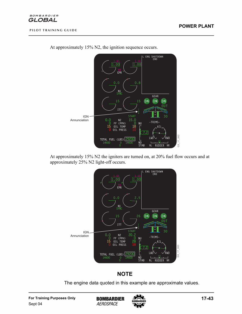
At approximately 15% N2, the ignition sequence occurs.
At approximately 15% N2 the igniters are turned on, at 20% fuel flow occurs and at approximately 25% N2 light-off occurs.
NOTEThe engine data quoted in this example are approximate values.
TOTAL FUEL (LBS) 292OO146OO 146OOO
N2
FF (PPH)
OIL TEMP
OIL PRESS
15.OO181O
START
NDSTAB
ITTSYNC
DN DN DN
OUT
3O
GEAR
–TRIMS–
NL NRRUDDER
AIL
RWDLWD
7.2
NU
O.OO15O
O
O.O
T/ON1SYNC
O.8
98.5 98.5
1.OO
1.55
TOEPR
1.OO
1.55
15 15
L ENG SHUTDOWNEND
GX
_1
7_
06
2
IGNAnnunciation
IGN
TOTAL FUEL (LBS) 292OO146OO 146OOO
N2
FF (PPH)
OIL TEMP
OIL PRESS
2O.2O2818
START
NDSTAB
ITTSYNC
DN DN DN
OUT
3O
GEAR
–TRIMS–
NL NRRUDDER
AIL
RWDLWD
7.2
NU
O.OO15O
O
O.O
T/ON1SYNC
2.5
98.5 98.5
1.OO
1.65
TOEPR
1.OO
1.65
15 26
L ENG SHUTDOWNEND
IGN
IGNAnnunciation
GX
_1
7_
06
3
17-44 For Training Purposes OnlySept 04
P I L O T T R A I N I N G G U I D E
POWER PLANT
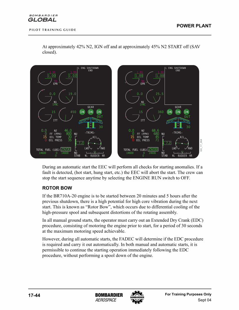
At approximately 42% N2, IGN off and at approximately 45% N2 START off (SAV closed).
During an automatic start the EEC will perform all checks for starting anomalies. If a fault is detected, (hot start, hung start, etc.) the EEC will abort the start. The crew can stop the start sequence anytime by selecting the ENGINE RUN switch to OFF.
ROTOR BOWIf the BR710A-20 engine is to be started between 20 minutes and 5 hours after the previous shutdown, there is a high potential for high core vibration during the next start. This is known as “Rotor Bow”, which occurs due to differential cooling of the high-pressure spool and subsequent distortions of the rotating assembly.
In all manual ground starts, the operator must carry out an Extended Dry Crank (EDC) procedure, consisting of motoring the engine prior to start, for a period of 30 seconds at the maximum motoring speed achievable.
However, during all automatic starts, the FADEC will determine if the EDC procedure is required and carry it out automatically. In both manual and automatic starts, it is permissible to continue the starting operation immediately following the EDC procedure, without performing a spool down of the engine.
TOTAL FUEL (LBS) 292OO146OO 146OOO
N2
FF (PPH)
OIL TEMP
OIL PRESS
68.668O4571
NDSTAB
ITTSYNC
DN DN DN
OUT
3O
GEAR
–TRIMS–
NL NRRUDDER
AIL
RWDLWD
7.2
NU
O.OO15O
O
O.O
T/ON1SYNC
25.5
98.5 98.5
1.OO
1.55
TOEPR
1.OO
1.55
15 36O
L ENG SHUTDOWNEND
TOTAL FUEL (LBS) 292OO146OO 146OOO
N2
FF (PPH)
OIL TEMP
OIL PRESS
46.O8OO3O35
NDSTAB
ITTSYNC
DN DN DN
OUT
3O
GEAR
–TRIMS–
NL NRRUDDER
AIL
RWDLWD
7.2
NU
O.OO15O
O
O.O
T/ON1SYNC
19.O
98.5 98.5
1.OO
1.55
TOEPR
1.O2
1.55
15 45O
L ENG SHUTDOWNEND
GX
_1
7_
06
4
For Training Purposes OnlySept 04
17-45
P I L O T T R A I N I N G G U I D E
POWER PLANT
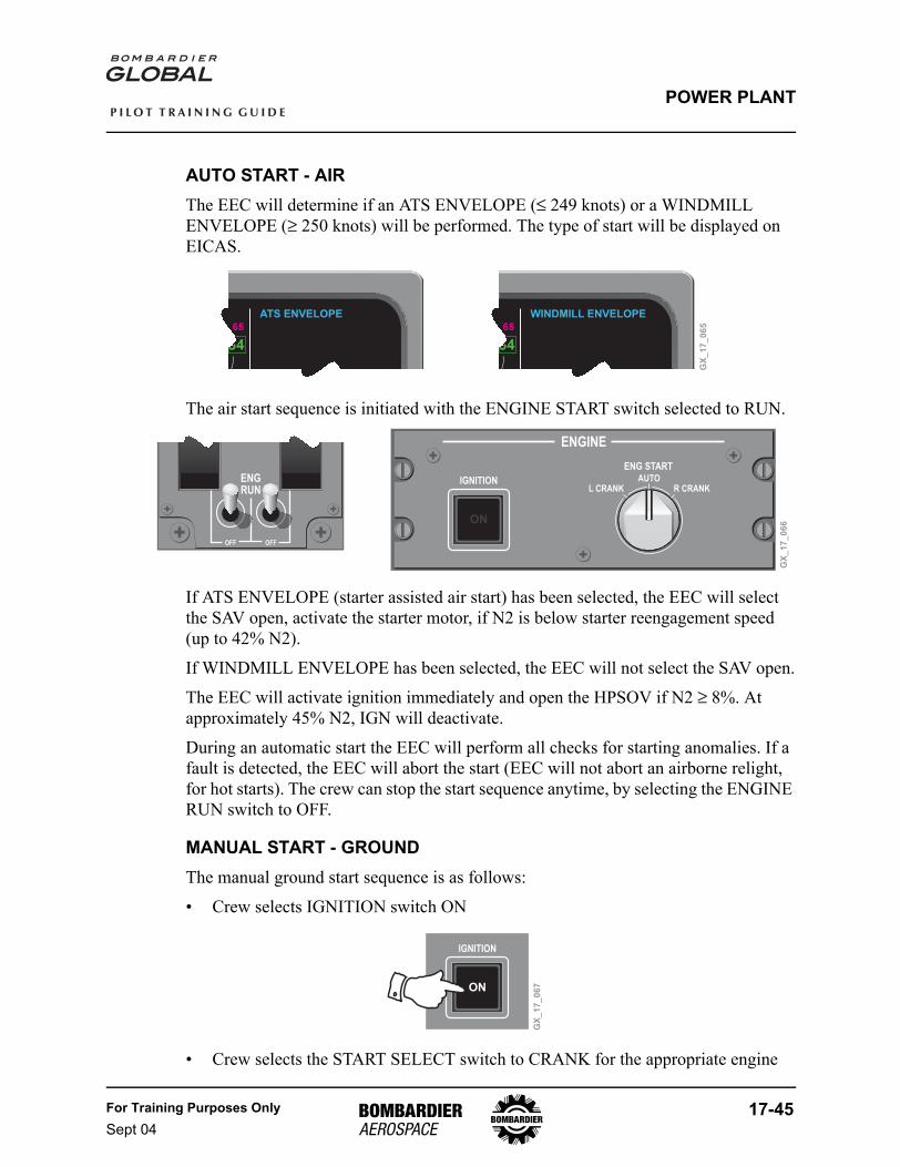
AUTO START - AIRThe EEC will determine if an ATS ENVELOPE (≤ 249 knots) or a WINDMILL ENVELOPE (≥ 250 knots) will be performed. The type of start will be displayed on EICAS.
The air start sequence is initiated with the ENGINE START switch selected to RUN.
If ATS ENVELOPE (starter assisted air start) has been selected, the EEC will select the SAV open, activate the starter motor, if N2 is below starter reengagement speed (up to 42% N2).
If WINDMILL ENVELOPE has been selected, the EEC will not select the SAV open.
The EEC will activate ignition immediately and open the HPSOV if N2 ≥ 8%. At approximately 45% N2, IGN will deactivate.
During an automatic start the EEC will perform all checks for starting anomalies. If a fault is detected, the EEC will abort the start (EEC will not abort an airborne relight, for hot starts). The crew can stop the start sequence anytime, by selecting the ENGINE RUN switch to OFF.
MANUAL START - GROUNDThe manual ground start sequence is as follows:
• Crew selects IGNITION switch ON
• Crew selects the START SELECT switch to CRANK for the appropriate engine
WINDMILL ENVELOPEATS ENVELOPE
GX
_1
7_
06
5
ENGRUN
OFF OFF
RL
ENGINE
ENG START
IGNITION
ON
AUTOL CRANK R CRANK
GX
_1
7_
06
6
IGNITION
ON
GX
_1
7_
06
7
17-46 For Training Purposes OnlySept 04
P I L O T T R A I N I N G G U I D E
POWER PLANT
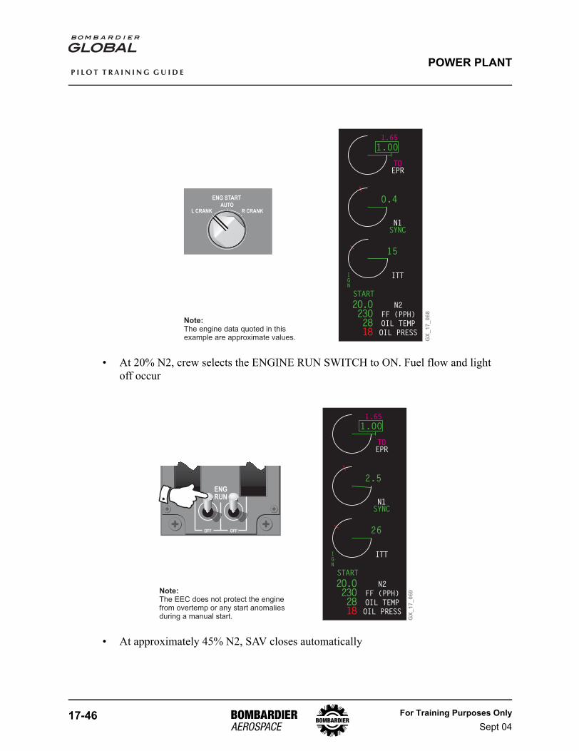
• At 20% N2, crew selects the ENGINE RUN SWITCH to ON. Fuel flow and light off occur
• At approximately 45% N2, SAV closes automatically
Note:The engine data quoted in thisexample are approximate values. G
X_
17
_0
68
ENG STARTAUTO
L CRANK R CRANK
N2
FF (PPH)
OIL TEMP
OIL PRESS
ITTSYNC
2O.O23O2818
O.4
T/ON1SYNC
98.5
1.OO
1.65
TOEPR
15
IGN
START
N2
FF (PPH)
OIL TEMP
OIL PRESS
ITTSYNC
2O.O23O2818
2.5
T/ON1SYNC
98.5
1.OO
1.65
TOEPR
26
IGN
START
ENGRUN
OFF OFF
RL
GX
_1
7_
06
9Note:The EEC does not protect the enginefrom overtemp or any start anomaliesduring a manual start.
For Training Purposes OnlySept 04
17-47
P I L O T T R A I N I N G G U I D E
POWER PLANT
During manual start, the EEC will not limit ITT, the crew has to abort the start in case of starting anomalies. After completion of the manual start sequence, the crew select IGNITION to Normal and returns the START SELECT switch to AUTO.
ENGINE SHUTDOWNThe normal engine shutdown sequence is as follows:
• Place thrust lever in Idle position
• Place ENGINE RUN switch to the OFF position, when engine has stabilized at Idle. Normal procedure is to stabilize engine at Idle for a 3-minute period
The EEC will reset (in preparation for the next engine start) after ENGINE RUN switch has been selected to OFF.
MAXTHRUST
IDLEREV
MAX REV
ENGRUN
OFF OFF
RL
GX
_1
7_
07
0
ENGRUN
OFF OFF
RL
GX
_1
7_
07
1
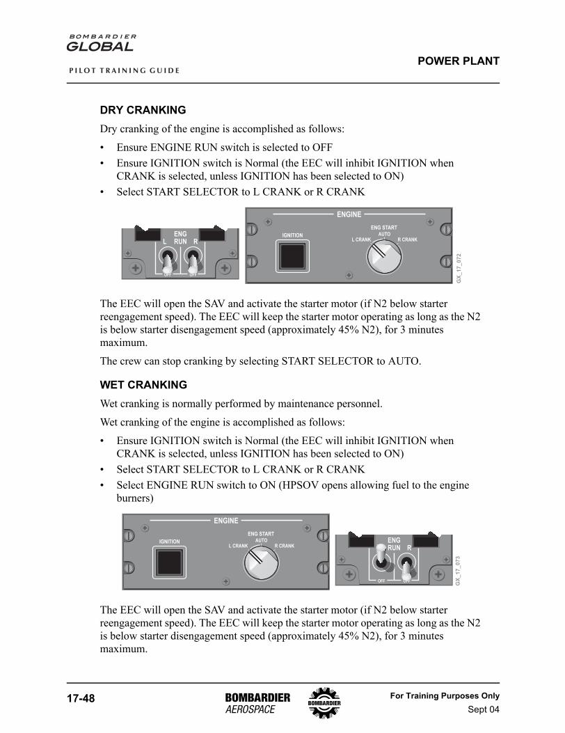
17-48 For Training Purposes OnlySept 04
P I L O T T R A I N I N G G U I D E
POWER PLANT
DRY CRANKINGDry cranking of the engine is accomplished as follows:
• Ensure ENGINE RUN switch is selected to OFF• Ensure IGNITION switch is Normal (the EEC will inhibit IGNITION when
CRANK is selected, unless IGNITION has been selected to ON)• Select START SELECTOR to L CRANK or R CRANK
The EEC will open the SAV and activate the starter motor (if N2 below starter reengagement speed). The EEC will keep the starter motor operating as long as the N2 is below starter disengagement speed (approximately 45% N2), for 3 minutes maximum.
The crew can stop cranking by selecting START SELECTOR to AUTO.
WET CRANKINGWet cranking is normally performed by maintenance personnel.
Wet cranking of the engine is accomplished as follows:
• Ensure IGNITION switch is Normal (the EEC will inhibit IGNITION when CRANK is selected, unless IGNITION has been selected to ON)
• Select START SELECTOR to L CRANK or R CRANK• Select ENGINE RUN switch to ON (HPSOV opens allowing fuel to the engine
burners)
The EEC will open the SAV and activate the starter motor (if N2 below starter reengagement speed). The EEC will keep the starter motor operating as long as the N2 is below starter disengagement speed (approximately 45% N2), for 3 minutes maximum.
GX
_1
7_
07
2
ENGINE
ENG START
IGNITION
ON
AUTOL CRANK R CRANK
ENGRUN
OFF OFF
RL
ENGINE
ENG START
IGNITION
ON
AUTOL CRANK R CRANK
ENGRUN
OFF OFF
RL
GX
_1
7_
07
3
For Training Purposes OnlySept 04
17-49
P I L O T T R A I N I N G G U I D E
POWER PLANT
STARTING ANOMALIES
AUTOMATIC GROUND START ABORTAny of the following events will result in an automatic ground start abort:
• Crew selecting ENGINE RUN switch to OFF• N2 speed not greater than or equal to 15% (120 seconds from ENGINE RUN
switch ON)• Idle speed not achieved (120 seconds from HPSOV open)• Starter cutout not being reached within starter duty timer (180 seconds from SAV
open)• ITT exceeding the ground start limit (700°C) after light-off and during acceleration
to Idle
MANUAL GROUND START ABORTAny of the following events will result in a manual ground start abort:
• Crew selecting ENGINE RUN switch to OFF• Crew selecting the START SELECTOR switch to AUTO• Crew selecting the IGNITION switch to Normal
AUTOMATIC AIR START ABORTAny of the following events will result in an automatic air start abort:
• Crew selecting ENGINE RUN switch to OFF• N2 speed not greater than or equal to 15% (60 seconds from ENGINE RUN switch
ON)• Idle speed not achieved (600 seconds from HPSOV open)• Starter cutout not being reached within inflight starter duty timer (180 seconds
from SAV open)
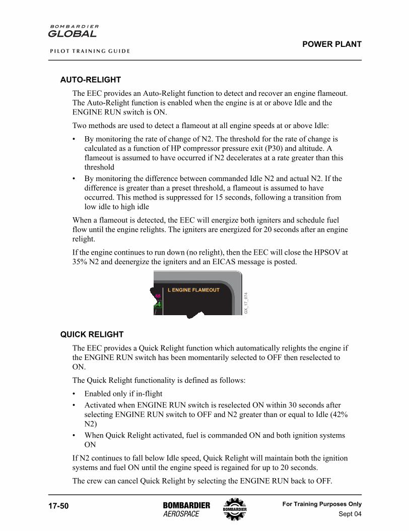
17-50 For Training Purposes OnlySept 04
P I L O T T R A I N I N G G U I D E
POWER PLANT
AUTO-RELIGHTThe EEC provides an Auto-Relight function to detect and recover an engine flameout. The Auto-Relight function is enabled when the engine is at or above Idle and the ENGINE RUN switch is ON.
Two methods are used to detect a flameout at all engine speeds at or above Idle:
• By monitoring the rate of change of N2. The threshold for the rate of change is calculated as a function of HP compressor pressure exit (P30) and altitude. A flameout is assumed to have occurred if N2 decelerates at a rate greater than this threshold
• By monitoring the difference between commanded Idle N2 and actual N2. If the difference is greater than a preset threshold, a flameout is assumed to have occurred. This method is suppressed for 15 seconds, following a transition from low idle to high idle
When a flameout is detected, the EEC will energize both igniters and schedule fuel flow until the engine relights. The igniters are energized for 20 seconds after an engine relight.
If the engine continues to run down (no relight), then the EEC will close the HPSOV at 35% N2 and deenergize the igniters and an EICAS message is posted.
QUICK RELIGHTThe EEC provides a Quick Relight function which automatically relights the engine if the ENGINE RUN switch has been momentarily selected to OFF then reselected to ON.
The Quick Relight functionality is defined as follows:
• Enabled only if in-flight• Activated when ENGINE RUN switch is reselected ON within 30 seconds after
selecting ENGINE RUN switch to OFF and N2 greater than or equal to Idle (42% N2)
• When Quick Relight activated, fuel is commanded ON and both ignition systems ON
If N2 continues to fall below Idle speed, Quick Relight will maintain both the ignition systems and fuel ON until the engine speed is regained for up to 20 seconds.
The crew can cancel Quick Relight by selecting the ENGINE RUN back to OFF.
GX
_1
7_
07
4
L ENGINE FLAMEOUT
For Training Purposes OnlySept 04
17-51
P I L O T T R A I N I N G G U I D E
POWER PLANT
AUTOTHROTTLE SYSTEMThe autothrottle system performs the following functions:
• Operation over the full range of available forward thrust for two engine operation. The autothrottle will not operate under single engine conditions
• Hands-off operation from takeoff to landing• Engine synchronization• Electronic Thrust Trim System (ETTS)
The A/T has two basic modes of operation:
1. Thrust control for the following AP/FD modes:- T/O (Takeoff)- GA (Go Around)- WS (Windshear)- FLC (Flight Level Change)
2. Speed control- For all other Flight Director modes
Note that the default operation for the A/T is speed control when no AP/FD modes are active.
AUTOTHROTTLE (A/T) DATA SOURCESThe A/T selects the IRS displayed on the coupled PFD as the IRS source during non-dual coupled AP/FD operation. During dual coupled AP/FD operation A/T selects the IRS displayed on each PFD and averages the data.
The A/T selects the ADC displayed on the coupled PFD as the ADC source during non-dual coupled Autopilot/Flight Director (AP/FD) operation. During dual coupled AP/FD operation A/T selects the ADC displayed on each PFD and averages the data.
A/T LIMITINGThe A/T system provides speed and thrust envelope limiting. Thrust envelope limiting is based on the active EPR rating, while speed envelope limiting is based on minimum speed limits as well as placard and structural speed limits.
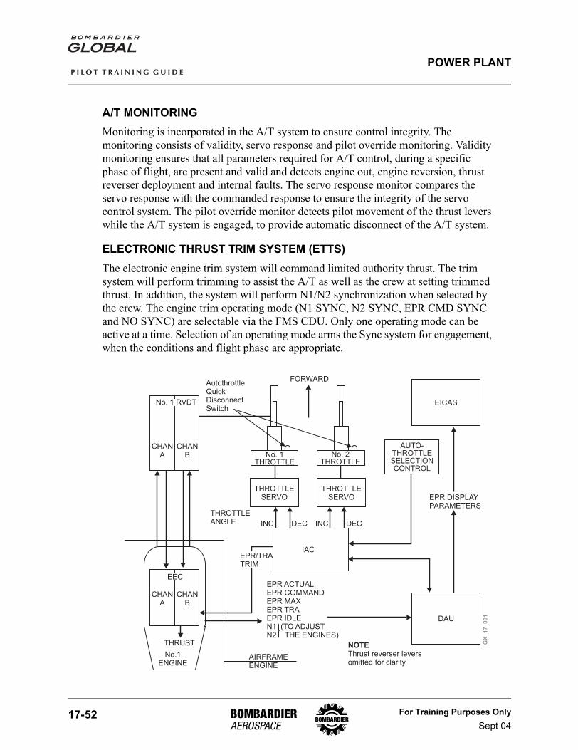
17-52 For Training Purposes OnlySept 04
P I L O T T R A I N I N G G U I D E
POWER PLANT
A/T MONITORINGMonitoring is incorporated in the A/T system to ensure control integrity. The monitoring consists of validity, servo response and pilot override monitoring. Validity monitoring ensures that all parameters required for A/T control, during a specific phase of flight, are present and valid and detects engine out, engine reversion, thrust reverser deployment and internal faults. The servo response monitor compares the servo response with the commanded response to ensure the integrity of the servo control system. The pilot override monitor detects pilot movement of the thrust levers while the A/T system is engaged, to provide automatic disconnect of the A/T system.
ELECTRONIC THRUST TRIM SYSTEM (ETTS)The electronic engine trim system will command limited authority thrust. The trim system will perform trimming to assist the A/T as well as the crew at setting trimmed thrust. In addition, the system will perform N1/N2 synchronization when selected by the crew. The engine trim operating mode (N1 SYNC, N2 SYNC, EPR CMD SYNC and NO SYNC) are selectable via the FMS CDU. Only one operating mode can be active at a time. Selection of an operating mode arms the Sync system for engagement, when the conditions and flight phase are appropriate.
GX
_1
7_
00
1
CHANA
CHANB
EEC
THRUST
No.1ENGINE
AIRFRAMEENGINE
EPR ACTUALEPR COMMANDEPR MAXEPR TRAEPR IDLEN1 (TO ADJUSTN2 THE ENGINES)
IAC
DAU
EICAS
NOTEThrust reverser leversomitted for clarity
THROTTLESERVO
THROTTLESERVO
EPR/TRATRIM
THROTTLEANGLE INC INCDEC DEC
No. 1THROTTLE
No. 2THROTTLE
FORWARD
AUTO-THROTTLESELECTIONCONTROL
EPR DISPLAYPARAMETERS
CHANA
CHANB
No. 1 RVDT
AutothrottleQuickDisconnectSwitch
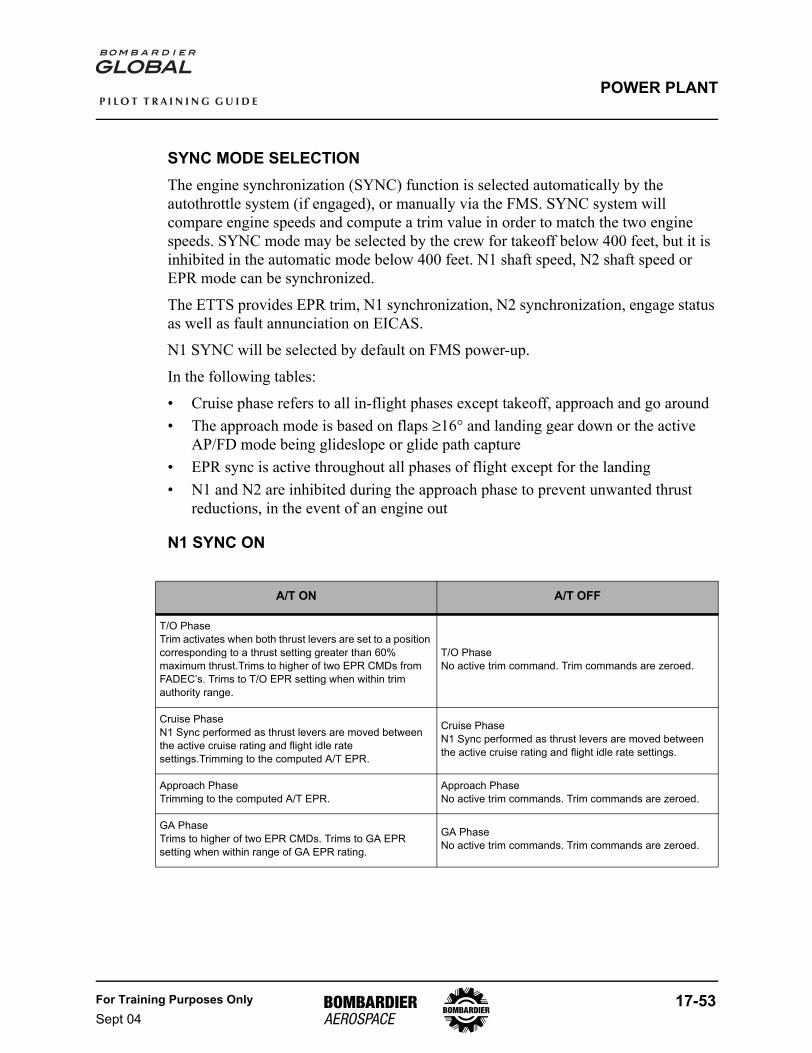
For Training Purposes OnlySept 04
17-53
P I L O T T R A I N I N G G U I D E
POWER PLANT
SYNC MODE SELECTIONThe engine synchronization (SYNC) function is selected automatically by the autothrottle system (if engaged), or manually via the FMS. SYNC system will compare engine speeds and compute a trim value in order to match the two engine speeds. SYNC mode may be selected by the crew for takeoff below 400 feet, but it is inhibited in the automatic mode below 400 feet. N1 shaft speed, N2 shaft speed or EPR mode can be synchronized.
The ETTS provides EPR trim, N1 synchronization, N2 synchronization, engage status as well as fault annunciation on EICAS.
N1 SYNC will be selected by default on FMS power-up.
In the following tables:
• Cruise phase refers to all in-flight phases except takeoff, approach and go around• The approach mode is based on flaps ≥16° and landing gear down or the active
AP/FD mode being glideslope or glide path capture• EPR sync is active throughout all phases of flight except for the landing• N1 and N2 are inhibited during the approach phase to prevent unwanted thrust
reductions, in the event of an engine out
N1 SYNC ON
A/T ON A/T OFF
T/O PhaseTrim activates when both thrust levers are set to a position corresponding to a thrust setting greater than 60% maximum thrust.Trims to higher of two EPR CMDs from FADEC’s. Trims to T/O EPR setting when within trim authority range.
T/O PhaseNo active trim command. Trim commands are zeroed.
Cruise PhaseN1 Sync performed as thrust levers are moved between the active cruise rating and flight idle rate settings.Trimming to the computed A/T EPR.
Cruise PhaseN1 Sync performed as thrust levers are moved between the active cruise rating and flight idle rate settings.
Approach PhaseTrimming to the computed A/T EPR.
Approach PhaseNo active trim commands. Trim commands are zeroed.
GA PhaseTrims to higher of two EPR CMDs. Trims to GA EPR setting when within range of GA EPR rating.
GA PhaseNo active trim commands. Trim commands are zeroed.
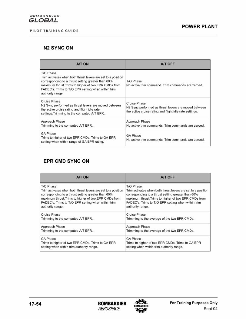
17-54 For Training Purposes OnlySept 04
P I L O T T R A I N I N G G U I D E
POWER PLANT
N2 SYNC ON
EPR CMD SYNC ON
A/T ON A/T OFF
T/O PhaseTrim activates when both thrust levers are set to a position corresponding to a thrust setting greater than 60% maximum thrust.Trims to higher of two EPR CMDs from FADEC’s. Trims to T/O EPR setting when within trim authority range.
T/O PhaseNo active trim command. Trim commands are zeroed.
Cruise PhaseN2 Sync performed as thrust levers are moved between the active cruise rating and flight idle rate settings.Trimming to the computed A/T EPR.
Cruise PhaseN2 Sync performed as thrust levers are moved between the active cruise rating and flight idle rate settings.
Approach PhaseTrimming to the computed A/T EPR.
Approach PhaseNo active trim commands. Trim commands are zeroed.
GA PhaseTrims to higher of two EPR CMDs. Trims to GA EPR setting when within range of GA EPR rating.
GA PhaseNo active trim commands. Trim commands are zeroed.
A/T ON A/T OFF
T/O PhaseTrim activates when both thrust levers are set to a position corresponding to a thrust setting greater than 60% maximum thrust.Trims to higher of two EPR CMDs from FADEC’s. Trims to T/O EPR setting when within trim authority range.
T/O PhaseTrim activates when both thrust levers are set to a position corresponding to a thrust setting greater than 60% maximum thrust.Trims to higher of two EPR CMDs from FADEC’s. Trims to T/O EPR setting when within trim authority range.
Cruise PhaseTrimming to the computed A/T EPR.
Cruise PhaseTrimming to the average of the two EPR CMDs.
Approach PhaseTrimming to the computed A/T EPR.
Approach PhaseTrimming to the average of the two EPR CMDs.
GA PhaseTrims to higher of two EPR CMDs. Trims to GA EPR setting when within trim authority range.
GA PhaseTrims to higher of two EPR CMDs. Trims to GA EPR setting when within trim authority range.
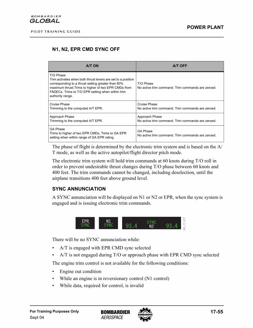
For Training Purposes OnlySept 04
17-55
P I L O T T R A I N I N G G U I D E
POWER PLANT
N1, N2, EPR CMD SYNC OFF
The phase of flight is determined by the electronic trim system and is based on the A/T mode, as well as the active autopilot/flight director pitch mode.
The electronic trim system will hold trim commands at 60 knots during T/O roll in order to prevent undesirable thrust changes during T/O phase between 60 knots and 400 feet. The trim commands cannot be changed, including deselection, until the airplane transitions 400 feet above ground level.
SYNC ANNUNCIATIONA SYNC annunciation will be displayed on N1 or N2 or EPR, when the sync system is engaged and is issuing electronic trim commands.
There will be no SYNC annunciation while:
• A/T is engaged with EPR CMD sync selected• A/T is not engaged during T/O or approach phase with EPR CMD sync selected
The engine trim control is not available for the following conditions:
• Engine out condition• While an engine is in reversionary control (N1 control)• While data, required for control, is invalid
A/T ON A/T OFF
T/O PhaseTrim activates when both thrust levers are set to a position corresponding to a thrust setting greater than 60% maximum thrust.Trims to higher of two EPR CMDs from FADECs. Trims to T/O EPR setting when within trim authority range.
T/O PhaseNo active trim command. Trim commands are zeroed.
Cruise PhaseTrimming to the computed A/T EPR.
Cruise PhaseNo active trim command. Trim commands are zeroed.
Approach PhaseTrimming to the computed A/T EPR.
Approach PhaseNo active trim command. Trim commands are zeroed.
GA PhaseTrims to higher of two EPR CMDs. Trims to GA EPR setting when within range of GA EPR rating.
GA PhaseNo active trim command. Trim commands are zeroed.
GX
_1
7_
01
7
EPRSYNC N2 93.4
START START
93.4SYNCN1
SYNC
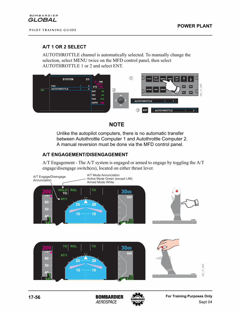
17-56 For Training Purposes OnlySept 04
P I L O T T R A I N I N G G U I D E
POWER PLANT
A/T 1 OR 2 SELECTAUTOTHROTTLE channel is automatically selected. To manually change the selection, select MENU twice on the MFD control panel, then select AUTOTHROTTLE 1 or 2 and select ENT.
NOTEUnlike the autopilot computers, there is no automatic transfer between Autothrottle Computer 1 and Autothrottle Computer 2.A manual reversion must be done via the MFD control panel.
A/T ENGAGEMENT/DISENGAGEMENTA/T Engagement - The A/T system is engaged or armed to engage by toggling the A/T engage/disengage switch(es), located on either thrust lever.
TCAS MENU
EMER
TERRMAP
PLAN
NAV
APT
NORM ABN
SKP
RCL
PAG
ENT
GX
_1
7_
00
2
ENT
SAT
GSPD
-56
TAT
TAS
-40
234
345
ETE 1+36
12 . 5KDVT
NMSYSTEM 2/3
WXAUTOTHROTTLE 21
FGC 2O 1
AUTOTHROTTLE 12
AUTOTHROTTLE 21
1
2
3
GX
_1
7_
00
3
A/T Engage/DisengageAnnunciation
A/T Mode AnnunciationActive Mode Green (except LIM)Armed Mode White
70
60
50
40
30
HOLD ROL TOAP1
AT/1
TO VAPP VNAV
500
10000
ATT2ADC1
20 20
10 10
20
200
1301
13000
200080
05
10 10
70
60
50
40
30
TO ROL TOAP1
AT/1
TO VAPP VNAV
500
10000
ATT2ADC1
20 20
10 10
20
200
1301
13000
200080
05
10 10
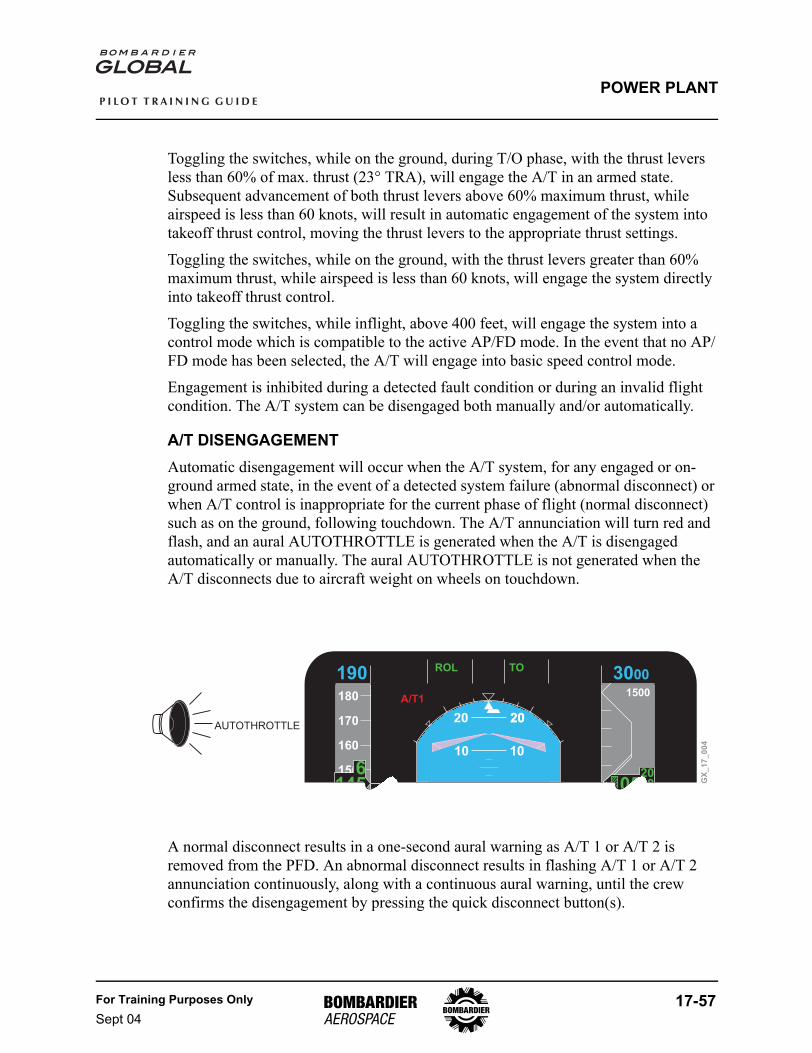
For Training Purposes OnlySept 04
17-57
P I L O T T R A I N I N G G U I D E
POWER PLANT
Toggling the switches, while on the ground, during T/O phase, with the thrust levers less than 60% of max. thrust (23° TRA), will engage the A/T in an armed state. Subsequent advancement of both thrust levers above 60% maximum thrust, while airspeed is less than 60 knots, will result in automatic engagement of the system into takeoff thrust control, moving the thrust levers to the appropriate thrust settings.
Toggling the switches, while on the ground, with the thrust levers greater than 60% maximum thrust, while airspeed is less than 60 knots, will engage the system directly into takeoff thrust control.
Toggling the switches, while inflight, above 400 feet, will engage the system into a control mode which is compatible to the active AP/FD mode. In the event that no AP/FD mode has been selected, the A/T will engage into basic speed control mode.
Engagement is inhibited during a detected fault condition or during an invalid flight condition. The A/T system can be disengaged both manually and/or automatically.
A/T DISENGAGEMENTAutomatic disengagement will occur when the A/T system, for any engaged or on-ground armed state, in the event of a detected system failure (abnormal disconnect) or when A/T control is inappropriate for the current phase of flight (normal disconnect) such as on the ground, following touchdown. The A/T annunciation will turn red and flash, and an aural AUTOTHROTTLE is generated when the A/T is disengaged automatically or manually. The aural AUTOTHROTTLE is not generated when theA/T disconnects due to aircraft weight on wheels on touchdown.
A normal disconnect results in a one-second aural warning as A/T 1 or A/T 2 is removed from the PFD. An abnormal disconnect results in flashing A/T 1 or A/T 2 annunciation continuously, along with a continuous aural warning, until the crew confirms the disengagement by pressing the quick disconnect button(s).
180
170
160
150
LIM ROL TOAP1
A/T1
SPD VAPP VNAV
1500
10000
ATT2ADC1
20 20
10 10
20
190
1456
3000
200080
05
10 10
GX
_1
7_
00
4
AUTOTHROTTLE
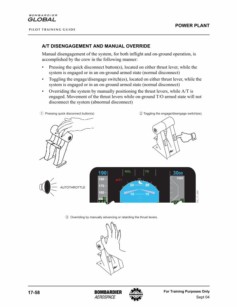
17-58 For Training Purposes OnlySept 04
P I L O T T R A I N I N G G U I D E
POWER PLANT
A/T DISENGAGEMENT AND MANUAL OVERRIDEManual disengagement of the system, for both inflight and on-ground operation, is accomplished by the crew in the following manner:
• Pressing the quick disconnect button(s), located on either thrust lever, while the system is engaged or in an on-ground armed state (normal disconnect)
• Toggling the engage/disengage switch(es), located on either thrust lever, while the system is engaged or in an on-ground armed state (normal disconnect)
• Overriding the system by manually positioning the thrust levers, while A/T is engaged. Movement of the thrust levers while on-ground T/O armed state will not disconnect the system (abnormal disconnect)
180
170
160
150
LIM ROL TOAP1
A/T1
SPD VAPP VNAV
1500
10000
ATT2ADC1
20 20
10 10
20
190
1456
3000
200080
05
10 10G
X_
17
_0
05
AUTOTHROTTLE
Toggling the engage/disengage switch(es)Pressing quick disconnect button(s)
Overriding by manually advancing or retarding the thrust levers.
1 2
3
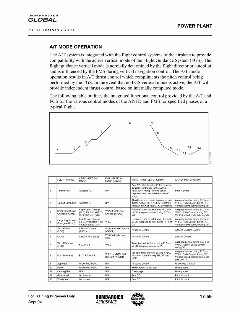
For Training Purposes OnlySept 04
17-59
P I L O T T R A I N I N G G U I D E
POWER PLANT
A/T MODE OPERATIONThe A/T system is integrated with the flight control systems of the airplane to provide compatibility with the active vertical mode of the Flight Guidance System (FGS). The flight guidance vertical mode is normally determined by the flight director or autopilot and is influenced by the FMS during vertical navigation control. The A/T mode operation results in A/T thrust control which compliments the pitch control being performed by the FGS. In the event that no FGS vertical mode is active, the A/T will provide independent thrust control based on internally computed mode.
The following table outlines the integrated functional control provided by the A/T and FGS for the various control modes of the AP/FD and FMS for specified phases of a typical flight.
FLIGHT PHASE AP/FD VERTICAL MODE
FMS VERTICAL MODE (VNAV) AUTOTHROTTLE FUNCTION AP/FD/FMS FUNCTION
1 Takeoff Roll Takeoff (TO) N/A
Sets TO rated thrust or FLEX reduced thrust by controlling to the MAX or FLEX EPR rating. Throttle servos depower when airspeed reaches 60 knots
Pitch Control
2 Takeoff Climb Out Takeoff (TO) N/AThrottle servos remain depowered until 400 ft. Above 400 ft AGL A/T controls to active MAX or FLEX T/O EPR rating
Airspeed control during FLC and VFLC. Pitch Control during PIT.Vertical speed control during VS
3 Small Flight Level Changes (Climb)
Flight Level Change (FLC), Pitch Hold (PIT) Vertical Speed (VS)
VNAV Flight Level Change (VFLC)
Reduced climb thrust during FLC and VFLC. Airspeed control during PIT and VS
Airspeed control during FLC and VFLC. Pitch Control during PIT.Vertical speed control during VS
4 Large Flight Level Changes (Climb)
Flight Level Change (FLC), Pitch Hold (PIT)Vertical Speed (VS)
VFLCReduced climb thrust during FLC and VFLC. Airspeed control during PIT and VS
Airspeed control during FLC and VFLC. Pitch Control during PIT.Vertical speed control during VS
5 Top of Climb (TOC)
Altitude Capture (ASEL)
VNAV Altitude Capture (VASEL) Airspeed Control Altitude Capture Control
6 Cruise Altitude Hold (ALT) VNAV Altitude Hold (VALT) Airspeed Control Altitude Control
7 Top of Descent (TOD) FLC or VS VFLC Transition to idle thrust during FLC and
VFLC. Airspeed control for VS
Airspeed control during FLC and VFLC. Vertical speed control during VS
8 FLC (Descent) FLC, PIT or VS VFLC or VNAV Path Descent (VPATH)
Full idle thrust during FLC and VFLC. Airspeed control during PIT, VS and VPATH
Airspeed control during FLC and VFLC. Pitch Control during PIT.Vertical speed control during VS and VPATH
9 Approach Glideslope Track N/A Airspeed Control Glideslope Control10 Flare Glideslope Track N/A Thrust retard to idle stop Disengaged11 Landing/Roll N/A N/A Disengaged Disengaged12 Go Around Go Around N/A Sets TO Pitch Control13 Windshear Windshear N/A Sets TO Pitch Control
GX
_1
7_
00
6
1 2
3
4
5 6 7
8
910
11
12 13
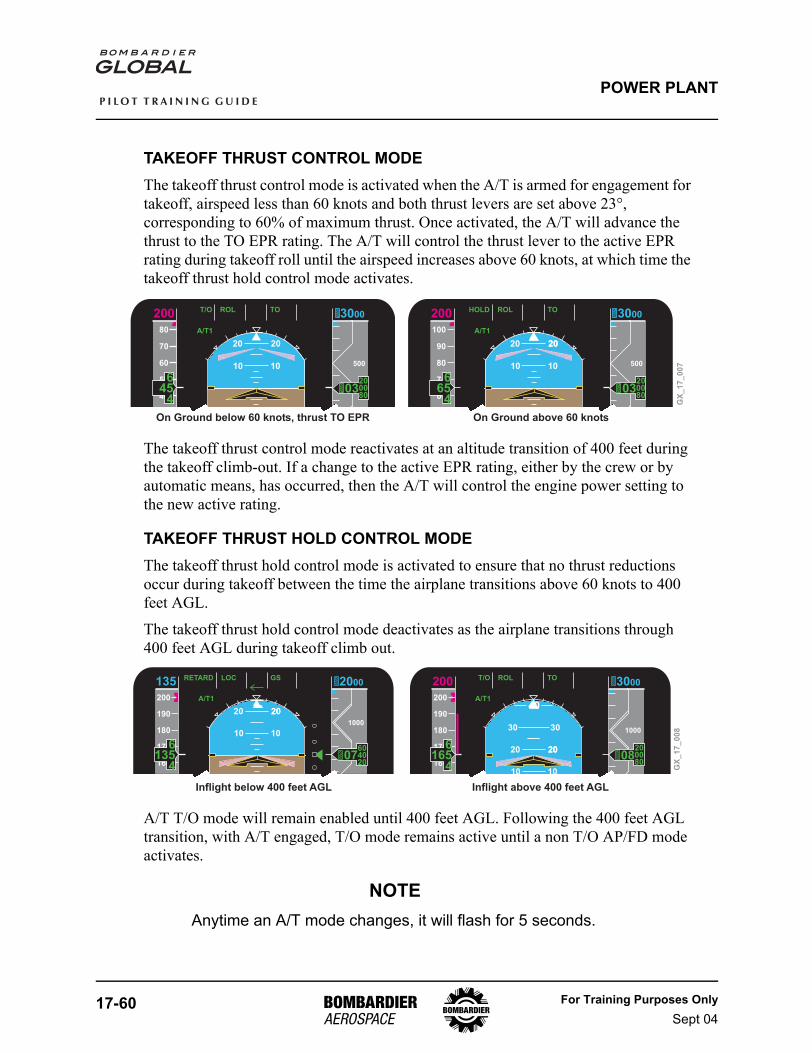
17-60 For Training Purposes OnlySept 04
P I L O T T R A I N I N G G U I D E
POWER PLANT
TAKEOFF THRUST CONTROL MODEThe takeoff thrust control mode is activated when the A/T is armed for engagement for takeoff, airspeed less than 60 knots and both thrust levers are set above 23°, corresponding to 60% of maximum thrust. Once activated, the A/T will advance the thrust to the TO EPR rating. The A/T will control the thrust lever to the active EPR rating during takeoff roll until the airspeed increases above 60 knots, at which time the takeoff thrust hold control mode activates.
The takeoff thrust control mode reactivates at an altitude transition of 400 feet during the takeoff climb-out. If a change to the active EPR rating, either by the crew or by automatic means, has occurred, then the A/T will control the engine power setting to the new active rating.
TAKEOFF THRUST HOLD CONTROL MODEThe takeoff thrust hold control mode is activated to ensure that no thrust reductions occur during takeoff between the time the airplane transitions above 60 knots to 400 feet AGL.
The takeoff thrust hold control mode deactivates as the airplane transitions through 400 feet AGL during takeoff climb out.
A/T T/O mode will remain enabled until 400 feet AGL. Following the 400 feet AGL transition, with A/T engaged, T/O mode remains active until a non T/O AP/FD mode activates.
NOTEAnytime an A/T mode changes, it will flash for 5 seconds.
GX
_1
7_
00
7
On Ground below 60 knots, thrust TO EPR On Ground above 60 knots
80
70
60
50
40
T/O ROL TOAP1
A/T1
SPD VAPP VNAV
500
ATT2ADC1
20 20
10 10
10 10
200
456
4
3000
20008060
03
100
90
80
70
60
HOLD ROL TOAP1
A/T1
SPD VAPP VNAV
500
ATT2ADC1
20 20
10 10
10 10
20
200
656
4
3000
20008060
03
200
190
180
170
160
RETARD LOC GSAP1
A/T1
SPD VAPP VNAV
1000
ATT2ADC1
20 20
10 10
20
135
1356
4
2000
604020
07
200
190
180
170
160
T/O ROL TOAP1
A/T1
SPD VAPP VNAV
1000
ATT2ADC1
20 20
10 10
20
40
3030
200
1656
4
3000
20008060
08
Inflight below 400 feet AGL Inflight above 400 feet AGL
GX
_1
7_
00
8
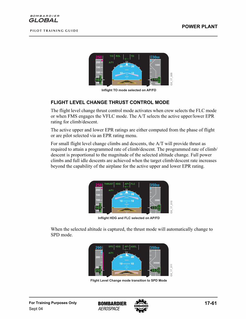
For Training Purposes OnlySept 04
17-61
P I L O T T R A I N I N G G U I D E
POWER PLANT
FLIGHT LEVEL CHANGE THRUST CONTROL MODEThe flight level change thrust control mode activates when crew selects the FLC mode or when FMS engages the VFLC mode. The A/T selects the active upper/lower EPR rating for climb/descent.
The active upper and lower EPR ratings are either computed from the phase of flight or are pilot selected via an EPR rating menu.
For small flight level change climbs and descents, the A/T will provide thrust as required to attain a programmed rate of climb/descent. The programmed rate of climb/descent is proportional to the magnitude of the selected altitude change. Full power climbs and full idle descents are achieved when the target climb/descent rate increases beyond the capability of the airplane for the active upper and lower EPR rating.
When the selected altitude is captured, the thrust mode will automatically change to SPD mode.
GX
_1
7_
00
9
Inflight TO mode selected on AP/FD
200
190
180
170
160
T/O ROL TOAP1
A/T1
SPD VAPP VNAV
1500
1000
ATT2ADC1
20 20
10 10
10 10
250
1656
4
3000
20008060
11
10 10
GX
_1
7_
01
0
Inflight HDG and FLC selected on AP/FD
200
190
180
170
160
THRUST HDG FLCAP1
A/T1
SPD VAPP VNAV
3500
ATT2ADC1
20 20
10 10
10 10
20
250
1656
4
35000
20008060
33
GX
_1
7_
011
Flight Level Change mode transition to SPD Mode
260
280
SPD HDG ASELAP1
A/T1
SPD VAPP VNAV
35500
ATT2ADC1
20 20
10 10
10 10
20
290
2556
4
35000
20008060
353
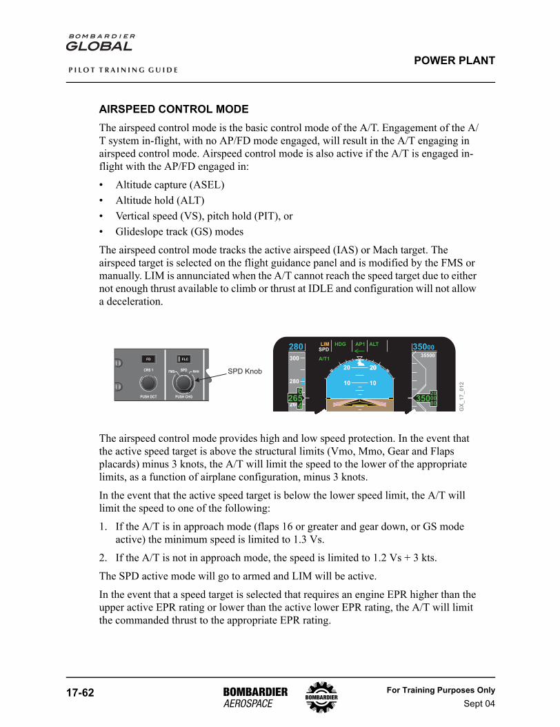
17-62 For Training Purposes OnlySept 04
P I L O T T R A I N I N G G U I D E
POWER PLANT
AIRSPEED CONTROL MODEThe airspeed control mode is the basic control mode of the A/T. Engagement of the A/T system in-flight, with no AP/FD mode engaged, will result in the A/T engaging in airspeed control mode. Airspeed control mode is also active if the A/T is engaged in-flight with the AP/FD engaged in:
• Altitude capture (ASEL)• Altitude hold (ALT)• Vertical speed (VS), pitch hold (PIT), or• Glideslope track (GS) modes
The airspeed control mode tracks the active airspeed (IAS) or Mach target. The airspeed target is selected on the flight guidance panel and is modified by the FMS or manually. LIM is annunciated when the A/T cannot reach the speed target due to either not enough thrust available to climb or thrust at IDLE and configuration will not allow a deceleration.
The airspeed control mode provides high and low speed protection. In the event that the active speed target is above the structural limits (Vmo, Mmo, Gear and Flaps placards) minus 3 knots, the A/T will limit the speed to the lower of the appropriate limits, as a function of airplane configuration, minus 3 knots.
In the event that the active speed target is below the lower speed limit, the A/T will limit the speed to one of the following:
1. If the A/T is in approach mode (flaps 16 or greater and gear down, or GS mode active) the minimum speed is limited to 1.3 Vs.
2. If the A/T is not in approach mode, the speed is limited to 1.2 Vs + 3 kts.
The SPD active mode will go to armed and LIM will be active.
In the event that a speed target is selected that requires an engine EPR higher than the upper active EPR rating or lower than the active lower EPR rating, the A/T will limit the commanded thrust to the appropriate EPR rating.
SPD MANFMSCRS 1
PUSH DCT
FD FLC
PUSH CHG
GX
_1
7_
01
2
SPD Knob
260
280
300
LIM HDG ALTAP1
A/T1
SPD VAPP VNAV
35500
35000
ATT2ADC1
20 20
10 10
10 10
20
280
2656
4
35000
20008060
350
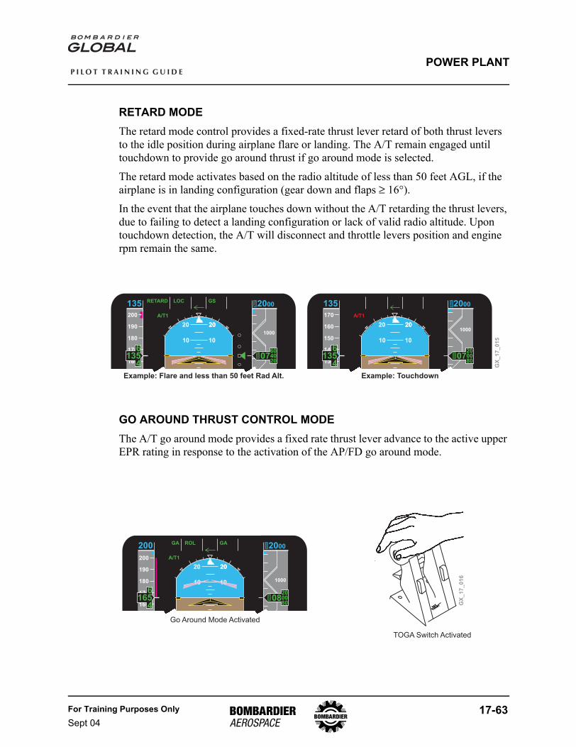
For Training Purposes OnlySept 04
17-63
P I L O T T R A I N I N G G U I D E
POWER PLANT
RETARD MODEThe retard mode control provides a fixed-rate thrust lever retard of both thrust levers to the idle position during airplane flare or landing. The A/T remain engaged until touchdown to provide go around thrust if go around mode is selected.
The retard mode activates based on the radio altitude of less than 50 feet AGL, if the airplane is in landing configuration (gear down and flaps ≥ 16°).
In the event that the airplane touches down without the A/T retarding the thrust levers, due to failing to detect a landing configuration or lack of valid radio altitude. Upon touchdown detection, the A/T will disconnect and throttle levers position and engine rpm remain the same.
GO AROUND THRUST CONTROL MODEThe A/T go around mode provides a fixed rate thrust lever advance to the active upper EPR rating in response to the activation of the AP/FD go around mode.
170
160
150
140
130
RETARD LOC GSAP1
A/T1
SPD VAPP VNAV
1000
ATT2ADC1
20 20
10 10
20
135
1356
4
2000
200080
07
200
190
180
170
160
RETARD LOC GSAP1
A/T1
SPD VAPP VNAV
1000
ATT2ADC1
20 20
10 10
20
135
1356
4
2000
604020
07
GX
_1
7_
01
5
Example: Flare and less than 50 feet Rad Alt. Example: Touchdown
GX
_1
7_
01
6
Go Around Mode Activated
TOGA Switch Activated
200
190
180
170
160
GA ROL GAAP1
A/T1
SPD VAPP VNAV
1000
ATT2ADC1
20 20
10 10
20
200
1656
4
2000
200080
08
10 10
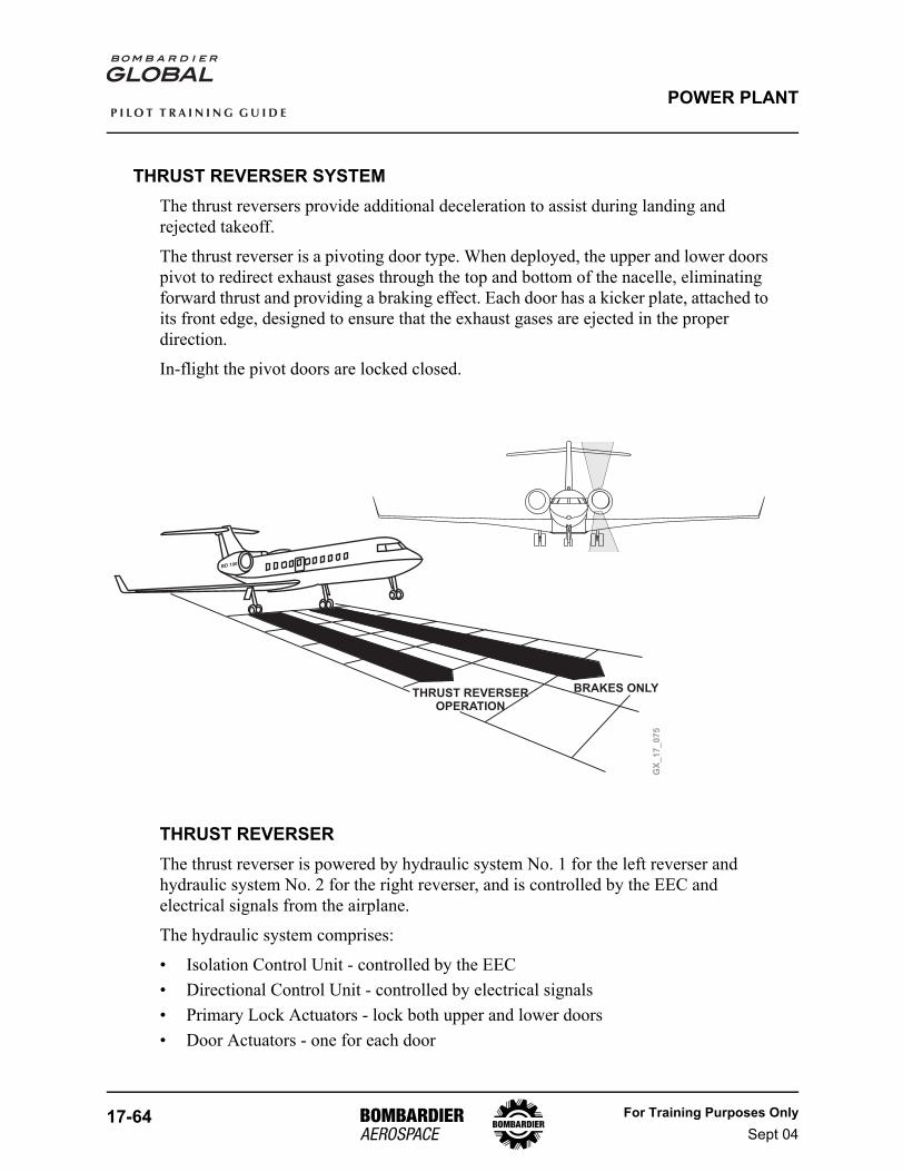
17-64 For Training Purposes OnlySept 04
P I L O T T R A I N I N G G U I D E
POWER PLANT
THRUST REVERSER SYSTEMThe thrust reversers provide additional deceleration to assist during landing and rejected takeoff.
The thrust reverser is a pivoting door type. When deployed, the upper and lower doors pivot to redirect exhaust gases through the top and bottom of the nacelle, eliminating forward thrust and providing a braking effect. Each door has a kicker plate, attached to its front edge, designed to ensure that the exhaust gases are ejected in the proper direction.
In-flight the pivot doors are locked closed.
THRUST REVERSERThe thrust reverser is powered by hydraulic system No. 1 for the left reverser and hydraulic system No. 2 for the right reverser, and is controlled by the EEC and electrical signals from the airplane.
The hydraulic system comprises:
• Isolation Control Unit - controlled by the EEC• Directional Control Unit - controlled by electrical signals• Primary Lock Actuators - lock both upper and lower doors• Door Actuators - one for each door
GX
_1
7_
07
5
THRUST REVERSEROPERATION
BRAKES ONLY
BD 100
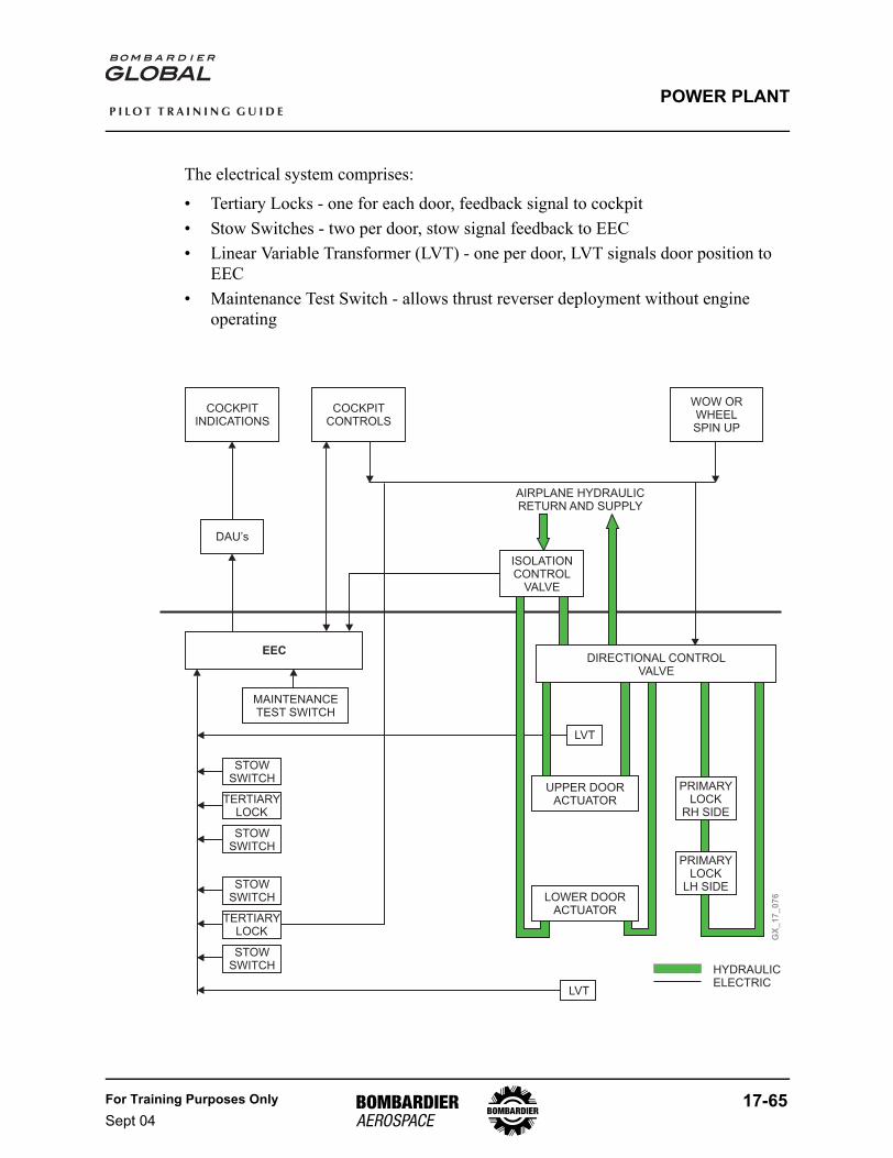
For Training Purposes OnlySept 04
17-65
P I L O T T R A I N I N G G U I D E
POWER PLANT
The electrical system comprises:
• Tertiary Locks - one for each door, feedback signal to cockpit• Stow Switches - two per door, stow signal feedback to EEC• Linear Variable Transformer (LVT) - one per door, LVT signals door position to
EEC• Maintenance Test Switch - allows thrust reverser deployment without engine
operating
GX
_1
7_
07
6
COCKPITCONTROLS
COCKPITINDICATIONS
WOW ORWHEELSPIN UP
DAU’s
ISOLATIONCONTROL
VALVE
DIRECTIONAL CONTROLVALVE
LVT
LVT
UPPER DOORACTUATOR
STOWSWITCH
MAINTENANCETEST SWITCH
TERTIARYLOCK
STOWSWITCH
STOWSWITCH
STOWSWITCH
LOWER DOORACTUATOR
PRIMARYLOCK
LH SIDE
PRIMARYLOCK
RH SIDE
AIRPLANE HYDRAULICRETURN AND SUPPLY
EEC
HYDRAULICELECTRIC
TERTIARYLOCK
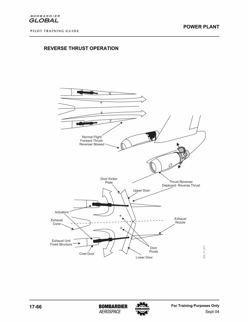
17-66 For Training Purposes OnlySept 04
P I L O T T R A I N I N G G U I D E
POWER PLANT
REVERSE THRUST OPERATION
ExhaustNozzle
Lower Door
Upper Door
Door KickerPlate
Actuators
ExhaustCone
Exhaust UnitFixed Structure
DoorPivots
Cowl Door
Thrust ReverserDeployed- Reverse Thrust
Normal FlightForward Thrust-Reverser Stowed
GX
_1
7_
07
7
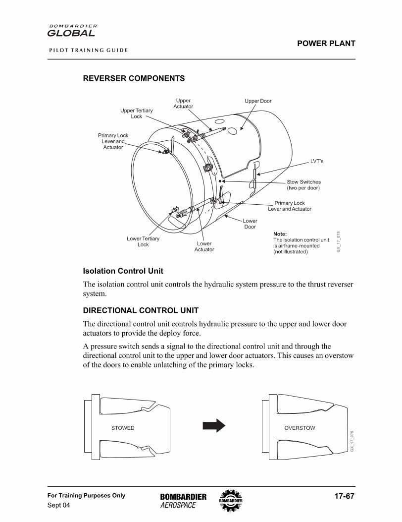
For Training Purposes OnlySept 04
17-67
P I L O T T R A I N I N G G U I D E
POWER PLANT
REVERSER COMPONENTS
Isolation Control UnitThe isolation control unit controls the hydraulic system pressure to the thrust reverser system.
DIRECTIONAL CONTROL UNITThe directional control unit controls hydraulic pressure to the upper and lower door actuators to provide the deploy force.
A pressure switch sends a signal to the directional control unit and through the directional control unit to the upper and lower door actuators. This causes an overstow of the doors to enable unlatching of the primary locks.
GX
_1
7_
07
8Note:The isolation control unitis airframe-mounted(not illustrated)
UpperActuator
Upper TertiaryLock
Primary LockLever andActuator
LowerActuator
Lower TertiaryLock
Primary LockLever and Actuator
Upper Door
LowerDoor
LVT’s
Stow Switches(two per door)
GX
_1
7_
07
9
STOWED OVERSTOW
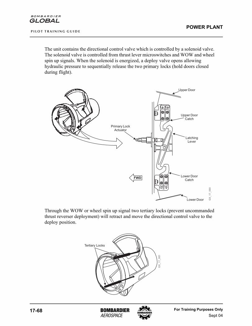
17-68 For Training Purposes OnlySept 04
P I L O T T R A I N I N G G U I D E
POWER PLANT
The unit contains the directional control valve which is controlled by a solenoid valve. The solenoid valve is controlled from thrust lever microswitches and WOW and wheel spin up signals. When the solenoid is energized, a deploy valve opens allowing hydraulic pressure to sequentially release the two primary locks (hold doors closed during flight).
Through the WOW or wheel spin up signal two tertiary locks (prevent uncommanded thrust reverser deployment) will retract and move the directional control valve to the deploy position.
GX
_1
7_
08
0
Upper Door
Upper DoorCatch
LatchingLever
Lower DoorCatch
Lower Door
Primary LockActuator
FWD
GX
_1
7_
08
1
Tertiary Locks
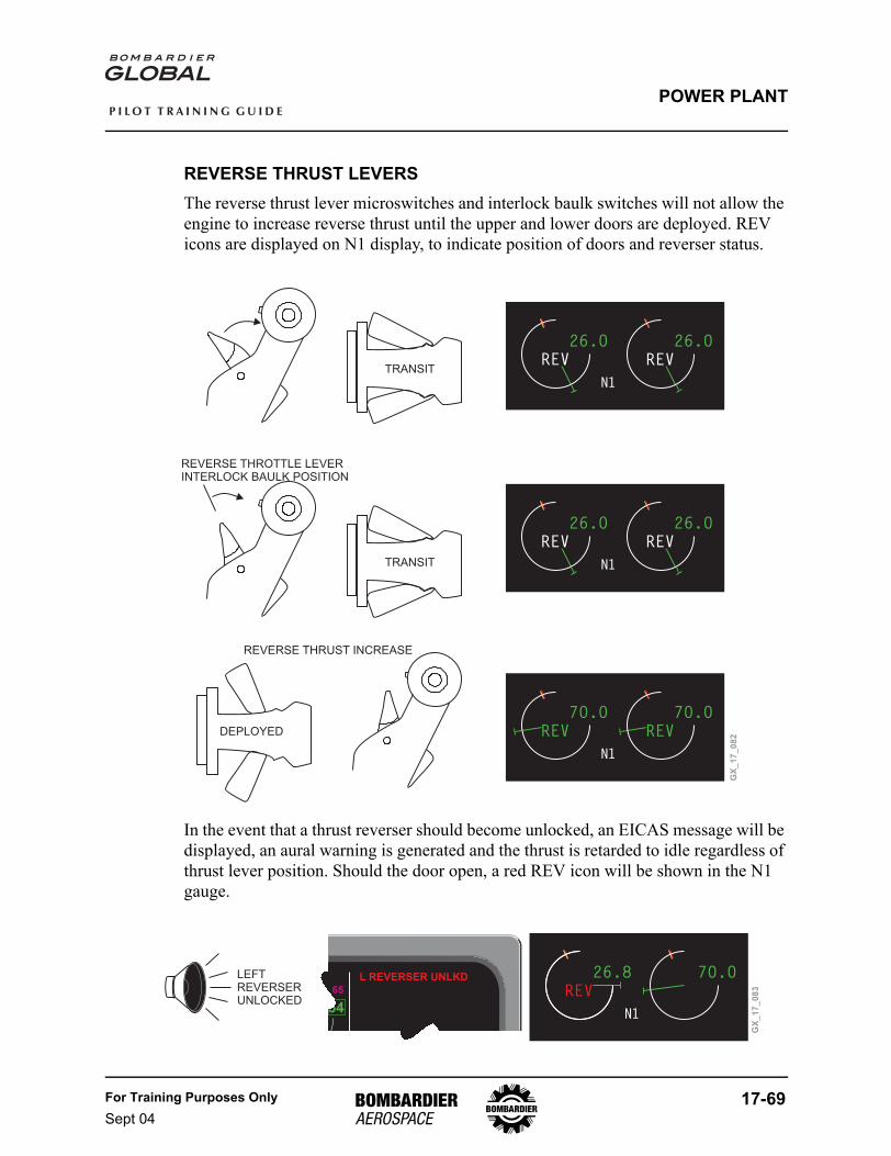
For Training Purposes OnlySept 04
17-69
P I L O T T R A I N I N G G U I D E
POWER PLANT
REVERSE THRUST LEVERSThe reverse thrust lever microswitches and interlock baulk switches will not allow the engine to increase reverse thrust until the upper and lower doors are deployed. REV icons are displayed on N1 display, to indicate position of doors and reverser status.
In the event that a thrust reverser should become unlocked, an EICAS message will be displayed, an aural warning is generated and the thrust is retarded to idle regardless of thrust lever position. Should the door open, a red REV icon will be shown in the N1 gauge.
7O.O
T/ON1
7O.O
26.O
T/ON1
26.O
26.O
T/ON1
26.O
GX
_1
7_
08
2
TRANSIT
DEPLOYED
TRANSIT
REVERSE THROTTLE LEVERINTERLOCK BAULK POSITION
REVERSE THRUST INCREASE
REV REV
REVREV
REV REV
26.8
T/ON1
7O.OL REVERSER UNLKD
GX
_1
7_
08
3
LEFTREVERSERUNLOCKED
REV
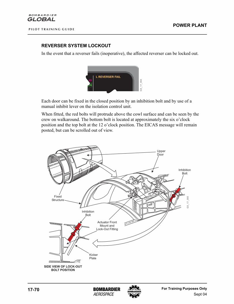
17-70 For Training Purposes OnlySept 04
P I L O T T R A I N I N G G U I D E
POWER PLANT
REVERSER SYSTEM LOCKOUTIn the event that a reverser fails (inoperative), the affected reverser can be locked out.
Each door can be fixed in the closed position by an inhibition bolt and by use of a manual inhibit lever on the isolation control unit.
When fitted, the red bolts will protrude above the cowl surface and can be seen by the crew on walkaround. The bottom bolt is located at approximately the six o’clock position and the top bolt at the 12 o’clock position. The EICAS message will remain posted, but can be scrolled out of view.
L REVERSER FAIL
GX
_1
7_
08
4
GX
_1
7_
08
5
Actuator FrontMount and
Lock-Out Fitting
KickerPlate
FixedStructure
UpperDoor
InhibitionBolt
InhibitionBolt
SIDE VIEW OF LOCK-OUTBOLT POSITION
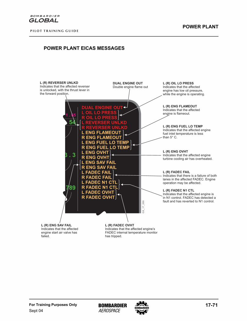
For Training Purposes OnlySept 04
17-71
P I L O T T R A I N I N G G U I D E
POWER PLANT
POWER PLANT EICAS MESSAGES
GX
_1
7_
08
6
789
1 . 65
DUAL ENGINE OUTL OIL LO PRESSR OIL LO PRESSL REVERSER UNLKDR REVERSER UNLKDL ENG FLAMEOUTR ENG FLAMEOUTL ENG FUEL LO TEMPR ENG FUEL LO TEMPL ENG OVHTR ENG OVHTL ENG SAV FAILR ENG SAV FAILL FADEC FAILR FADEC FAILL FADEC N1 CTLR FADEC N1 CTLL FADEC OVHTR FADEC OVHT
L (R) REVERSER UNLKDIndicates that the affected reverseris unlocked, with the thrust lever inthe forward position.
L (R) OIL LO PRESSIndicates that the affectedengine has low oil pressure,while the engine is operating.
L (R) ENG FLAMEOUTIndicates that the affectedengine is flameout.
L (R) ENG FUEL LO TEMPIndicates that the affected enginefuel inlet temperature is lessthan 5 C.°
L (R) ENG OVHTIndicates that the affected engineturbine cooling air has overheated.
L (R) FADEC FAILIndicates that there is a failure of bothlanes in the affected FADEC. Engineoperation may be affected.
L (R) FADEC N1 CTLIndicates that the affected engine isin N1 control. FADEC has detected afault and has reverted to N1 control.
L (R) FADEC OVHTIndicates that the affected engine’sFADEC internal temperature monitorhas tripped.
L (R) ENG SAV FAILIndicates that the affectedengine start air valve hasfailed.
DUAL ENGINE OUTDouble engine flame out
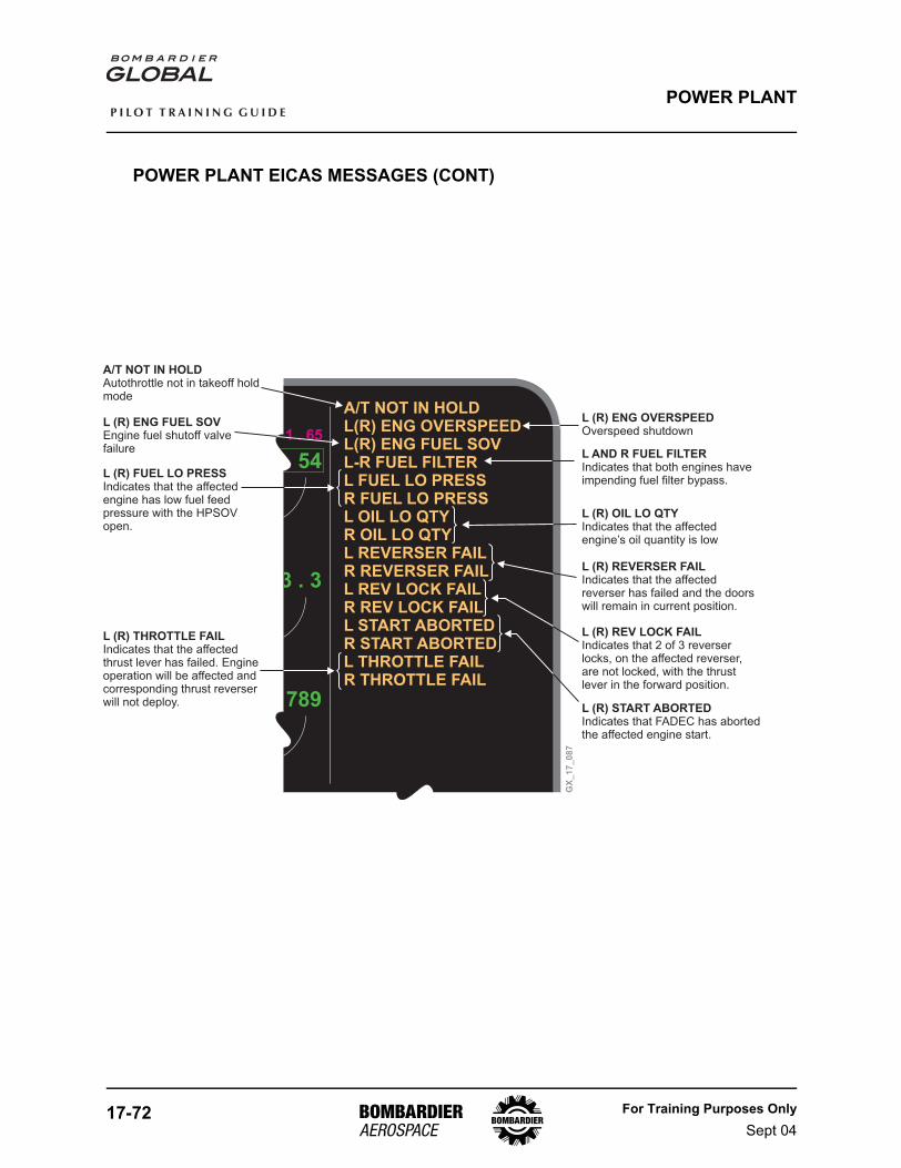
17-72 For Training Purposes OnlySept 04
P I L O T T R A I N I N G G U I D E
POWER PLANT
POWER PLANT EICAS MESSAGES (CONT)
GX
_1
7_
08
7
789
1 . 65
A/T NOT IN HOLDL(R) ENG OVERSPEEDL(R) ENG FUEL SOVL-R FUEL FILTERL FUEL LO PRESSR FUEL LO PRESSL OIL LO QTYR OIL LO QTYL REVERSER FAILR REVERSER FAILL REV LOCK FAILR REV LOCK FAILL START ABORTEDR START ABORTEDL THROTTLE FAILR THROTTLE FAIL
L (R) FUEL LO PRESSIndicates that the affectedengine has low fuel feedpressure with the HPSOVopen.
L AND R FUEL FILTERIndicates that both engines haveimpending fuel filter bypass.
L (R) OIL LO QTYIndicates that the affectedengine’s oil quantity is low
L (R) REVERSER FAILIndicates that the affectedreverser has failed and the doorswill remain in current position.
L (R) REV LOCK FAILIndicates that 2 of 3 reverserlocks, on the affected reverser,are not locked, with the thrustlever in the forward position.
L (R) START ABORTEDIndicates that FADEC has abortedthe affected engine start.
L (R) THROTTLE FAILIndicates that the affectedthrust lever has failed. Engineoperation will be affected andcorresponding thrust reverserwill not deploy.
A/T NOT IN HOLDAutothrottle not in takeoff holdmode
L (R) ENG FUEL SOVEngine fuel shutoff valvefailure
L (R) ENG OVERSPEEDOverspeed shutdown
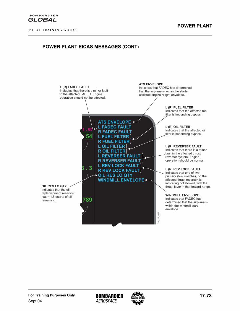
For Training Purposes OnlySept 04
17-73
P I L O T T R A I N I N G G U I D E
POWER PLANT
POWER PLANT EICAS MESSAGES (CONT)
GX
_1
7_
08
8
789
1 . 65
ATS ENVELOPEL FADEC FAULTR FADEC FAULTL FUEL FILTERR FUEL FILTERL OIL FILTERR OIL FILTERL REVERSER FAULTR REVERSER FAULTL REV LOCK FAULTR REV LOCK FAULTOIL RES LO QTYWINDMILL ENVELOPE
L (R) FADEC FAULTIndicates that there is a minor faultin the affected FADEC. Engineoperation should not be affected.
ATS ENVELOPEIndicates that FADEC has determinedthat the airplane is within the starterassisted engine relight envelope.
L (R) FUEL FILTERIndicates that the affected fuelfilter is impending bypass.
L (R) OIL FILTERIndicates that the affected oilfilter is impending bypass.
L (R) REVERSER FAULTIndicates that there is a minorfault in the affected thrustreverser system. Engineoperation should be normal.
L (R) REV LOCK FAULTIndicates that one of twoprimary stow switches, on theaffected thrust reverser, isindicating not stowed, with thethrust lever in the forward range.
WINDMILL ENVELOPEIndicates that FADEC hasdetermined that the airplane iswithin the windmill startenvelope.
OIL RES LO QTYIndicates that the oilreplenishment reservoirhas < 1.5 quarts of oilremaining.
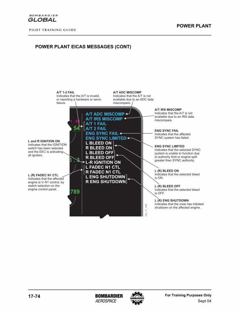
17-74 For Training Purposes OnlySept 04
P I L O T T R A I N I N G G U I D E
POWER PLANT
POWER PLANT EICAS MESSAGES (CONT)
GX
_1
7_
08
9
789
1 . 65
A/T ADC MISCOMPA/T IRS MISCOMPA/T 1 FAILA/T 2 FAILENG SYNC FAILENG SYNC LIMITEDL BLEED ONR BLEED ONL BLEED OFFR BLEED OFFL-R IGNITION ONL FADEC N1 CTLR FADEC N1 CTLL ENG SHUTDOWNR ENG SHUTDOWN
A/T 1-2 FAILIndicates that the A/T is invalid,or reporting a hardware or servofailure.
A/T ADC MISCOMPIndicates that the A/T is notavailable due to an ADC datamiscompare.
A/T IRS MISCOMPIndicates that the A/T is notavailable due to an IRS datamiscompare.
ENG SYNC FAILIndicates that the affectedSYNC system has failed.
ENG SYNC LIMITEDIndicates that the selected SYNCsystem is unable to function dueto authority limit or engine splitgreater than SYNC authority.
L (R) BLEED ONIndicates that the selected bleedis ON.
L (R) BLEED OFFIndicates that the selected bleedis OFF.
L (R) FADEC N1 CTLIndicates that the affectedengine is in N1 control, byswitch selection on theengine control panel.
L (R) ENG SHUTDOWNIndicates that the crew has initiatedshutdown on the affected engine.
L and R IGNITION ONIndicates that the IGNITIONswitch has been selectedand the EEC is activatingall igniters.
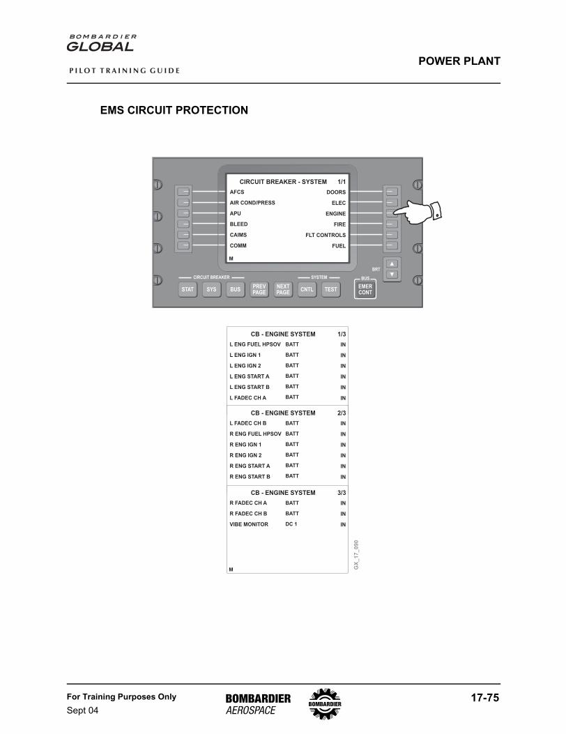
For Training Purposes OnlySept 04
17-75
P I L O T T R A I N I N G G U I D E
POWER PLANT
EMS CIRCUIT PROTECTION
M
M
M
M
BRT
CIRCUIT BREAKER SYSTEM
STAT SYS BUSPREVPAGE
NEXTPAGE
CNTL TEST
BUS
EMERCONT
GX
_1
7_
09
0
CB - ENGINE SYSTEM 1/3
L ENG FUEL HPSOV
L ENG IGN 1
L ENG IGN 2
L ENG START A
L ENG START B
L FADEC CH A
BATT
BATT
BATT
BATT
BATT
BATT
IN
IN
IN
IN
IN
IN
CB - ENGINE SYSTEM 2/3
L FADEC CH B
R ENG FUEL HPSOV
R ENG IGN 1
R ENG IGN 2
R ENG START A
R ENG START B
BATT
BATT
BATT
BATT
BATT
BATT
IN
IN
IN
IN
IN
IN
CB - ENGINE SYSTEM 3/3
R FADEC CH A
R FADEC CH B
VIBE MONITOR
BATT
BATT
DC 1
IN
IN
IN
CIRCUIT BREAKER - SYSTEM 1/1
AFCS
AIR COND/PRESS
APU
BLEED
CAIMS
COMM
DOORS
ELEC
ENGINE
FIRE
FLT CONTROLS
FUEL
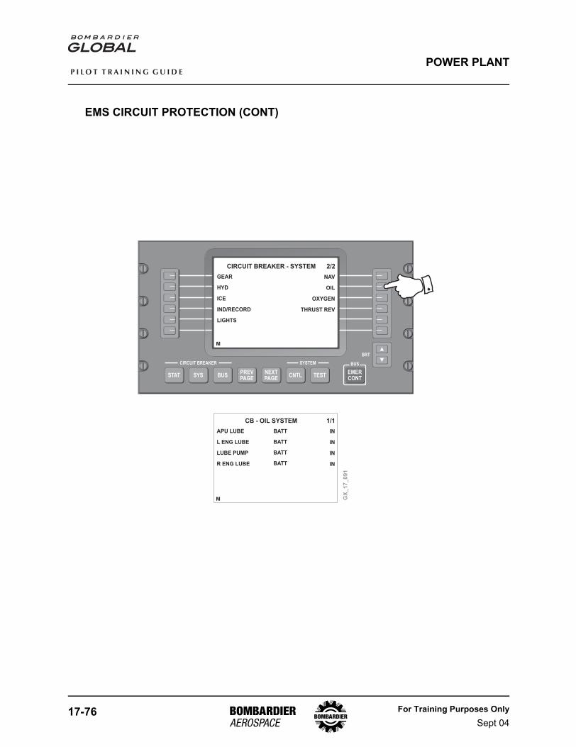
17-76 For Training Purposes OnlySept 04
P I L O T T R A I N I N G G U I D E
POWER PLANT
EMS CIRCUIT PROTECTION (CONT)
M
M
BRT
CIRCUIT BREAKER SYSTEM
STAT SYS BUSPREVPAGE
NEXTPAGE
CNTL TEST
BUS
EMERCONT
GX
_1
7_
09
1
CB - OIL SYSTEM 1/1
APU LUBE
L ENG LUBE
LUBE PUMP
R ENG LUBE
BATT
BATT
BATT
BATT
IN
IN
IN
IN
CIRCUIT BREAKER - SYSTEM 2/2
GEAR
HYD
ICE
IND/RECORD
LIGHTS
NAV
OIL
OXYGEN
THRUST REV
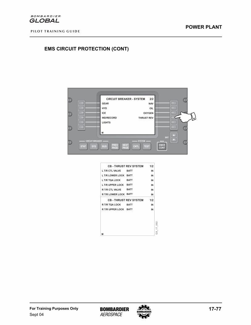
For Training Purposes OnlySept 04
17-77
P I L O T T R A I N I N G G U I D E
POWER PLANT
EMS CIRCUIT PROTECTION (CONT)
M
M
M
BRT
CIRCUIT BREAKER SYSTEM
STAT SYS BUSPREVPAGE
NEXTPAGE
CNTL TEST
BUS
EMERCONT
CIRCUIT BREAKER - SYSTEM 2/2
GEAR
HYD
ICE
IND/RECORD
LIGHTS
NAV
OIL
OXYGEN
THRUST REV
GX
_1
7_
09
2
CB - THRUST REV SYSTEM 1/2
L T/R CTL VALVE
L T/R LOWER LOCK
L T/R TQA LOCK
L T/R UPPER LOCK
R T/R CTL VALVE
R T/R LOWER LOCK
BATT
BATT
BATT
BATT
BATT
BATT
IN
IN
IN
IN
IN
IN
CB - THRUST REV SYSTEM 1/2
R T/R TQA LOCK
R T/R UPPER LOCK
BATT
BATT
IN
IN

17-78 For Training Purposes OnlySept 04
P I L O T T R A I N I N G G U I D E
POWER PLANT
PAGE INTENTIONALLY LEFT BLANK