Embed Size (px)
Citation preview
International Journal of Solids and Structures 43 (2006) 5713–5735
www.elsevier.com/locate/ijsolstr
Postbuckling analysis of laminated composite platessubjected to the combination of in-plane shear,
compression and lateral loading
Sung-Cheon Han a,*, Sang-Youl Lee c, Guillermo Rus b
a Department of Civil Engineering, Daewon Science College, 599 Shinwol, Jecheon 390-702, Koreab Department of Structural Mechanics, University of Granada, Politecnico de Fuentenueva, 18071 Granada, Spain
c Department of Civil Engineering, Hanyang University, 17, Haeongdang-Dong, Seongdong-gu Seoul 133-791, South Korea
Received 9 May 2005Available online 11 October 2005
Abstract
This study deals with postbuckling behavior of laminated composite plates under the combination of in-plane shear,compression and lateral loading using an Element-based Lagrangian formulation. Natural co-ordinate-based strains, stres-ses and constitutive equations are used in the present shell element. The Element-based Lagrangian formulation describedin this paper, in comparison with the traditional approaches, is more attractive not only because it uses only single map-ping but also it converges faster. In addition, the finite element (FE) formulation based on the assumed natural strainmethod for composite structures shows excellence from the standpoints of computational efficiency as well as its abilityto avoid both membrane and shear locking behavior. The numerical results obtained are in good agreement with thosereported by other investigators. In particular, new results reported in this paper show the influence of various types of load-ing, materials and number of layers on postbuckling behavior.� 2005 Elsevier Ltd. All rights reserved.
Keywords: Element-based Lagrangian formulation; A 9-node assumed strain shell element; Postbuckling; Laminated composite plates;Combination of in-plane shear and lateral loading
1. Introduction
A new class of materials, fiber-reinforced composite materials, is increasingly being used in a large varietyof structures including aerospace, marine and civil infrastructure. With the advancement of technology infiber-reinforced composite materials, the applicability of composites to such structures has been increasedsignificantly due to their merits such as high strength to weight ratio and resistance to corrosion.
Structural behavior of plates and shells using the finite element method has been studied by a variety ofapproaches. Ahmad et al. (1970) developed shell elements referred as degenerate model. In general, such shell
0020-7683/$ - see front matter � 2005 Elsevier Ltd. All rights reserved.
doi:10.1016/j.ijsolstr.2005.08.004
* Corresponding author. Tel.: +82 43 649 3267; fax: +82 43 649 3555.E-mail address: [email protected] (S.-C. Han).
5714 S.-C. Han et al. / International Journal of Solids and Structures 43 (2006) 5713–5735
elements can describe accurately the various behaviors of plates and shells. However, for the thin structures,their performance deteriorates rapidly as the element thickness becomes thin, which is called shear locking. Inorder to overcome the shear locking problems Huang and Hinton (1986) developed a nine-node assumedstrain shell element using an enhanced interpolation of the transverse shear strains in the natural coordinatesystem. Other finite elements employing the assumed strain method were then reported by Jang and Pinsky(1987) independently and also a various background of the assumed strain method was presented by Simoand Hughes (1986). Belytschko et al. (1989) presented a nine-node assumed strain shell element with a stabi-lized matrix to control the zero energy modes and used a reduced integration for all the terms.
Based on the finite element techniques, various geometrically nonlinear formulations for laminated com-posite structures are developed in the last two decades. Kim and Voyiadjis (1999) analyzed postbucklingbehaviors of laminated composite panels under in-plane compression. Kim et al. (2003) carried out initialbuckling and postbuckling analysis of composite plates under pure shear loading. However, the papers onthe postbuckling analysis of the laminated composite plates under the combination of in-plane shear, com-pression and lateral loading have rarely been published. Moreover, most previous studies dealing with com-posites and isotropic plates subjected to the compressive and combined loading have been limited to elasticbuckling behaviors (Featherston and Watson, 2005; Shufrin and Eisenberger, 2005; Featherston, 2003;Loughlan, 2001).
In this paper, to avoid locking phenomena, the assumed natural strain method by Han et al. (2004) is usedand the equivalent constitutive equations is used to capture layer effect through the thickness direction. Weconcentrate on the postbuckling analysis of laminated composite plates under the combination of in-planeshear, compression and lateral loading. For a composite laminate, the combination of various types of loadingand lay-up sequences could play a dominant role in determining the nonlinear characteristics. Thus, the studyis further extended in this investigation to take into account the effects of loading and stacking sequences. Thisstudy uses the first-order shear deformation theory and the numerical results are verified by comparing themwith the solutions obtained by Zhang and Matthews (1983a,b, 1985).
2. Geometry of the shell element
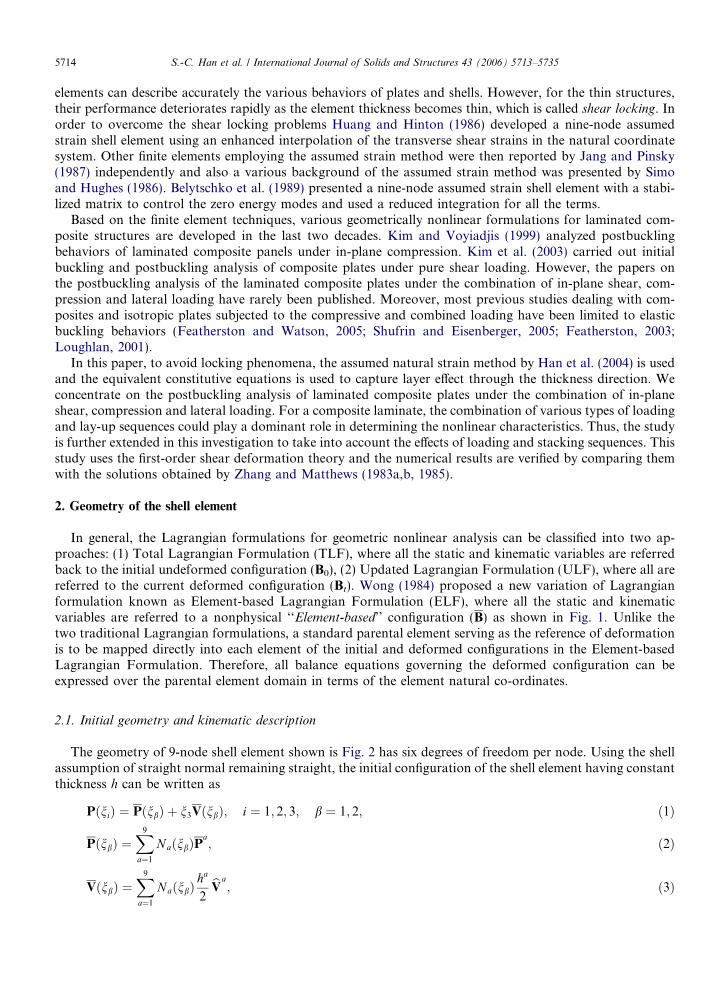
In general, the Lagrangian formulations for geometric nonlinear analysis can be classified into two ap-proaches: (1) Total Lagrangian Formulation (TLF), where all the static and kinematic variables are referredback to the initial undeformed configuration (B0), (2) Updated Lagrangian Formulation (ULF), where all arereferred to the current deformed configuration (Bt). Wong (1984) proposed a new variation of Lagrangianformulation known as Element-based Lagrangian Formulation (ELF), where all the static and kinematicvariables are referred to a nonphysical ‘‘Element-based’’ configuration (B) as shown in Fig. 1. Unlike thetwo traditional Lagrangian formulations, a standard parental element serving as the reference of deformationis to be mapped directly into each element of the initial and deformed configurations in the Element-basedLagrangian Formulation. Therefore, all balance equations governing the deformed configuration can beexpressed over the parental element domain in terms of the element natural co-ordinates.
2.1. Initial geometry and kinematic description
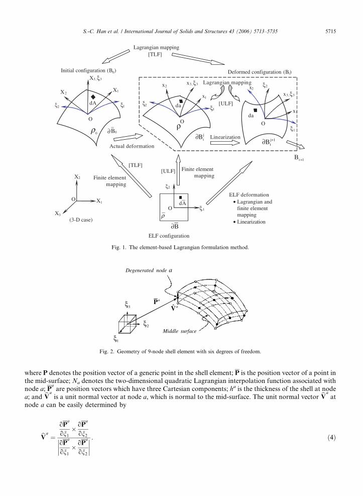
The geometry of 9-node shell element shown is Fig. 2 has six degrees of freedom per node. Using the shellassumption of straight normal remaining straight, the initial configuration of the shell element having constantthickness h can be written as
PðniÞ ¼ PðnbÞ þ n3VðnbÞ; i ¼ 1; 2; 3; b ¼ 1; 2; ð1Þ
PðnbÞ ¼X9
a¼1
NaðnbÞPa; ð2Þ
VðnbÞ ¼X9
a¼1
NaðnbÞha
2bVa; ð3Þ
O
ξ1ξ2
X3, ξ3
X1X2
dA
0ρ 0B∂
O
ξ1
ξ2
x3, ξ3
x1
x2
da
Oξ1
ξ2
x3, ξ3
x1
x2
Lagrangian mapping
Linearization
[ULF]
[TLF]
Deformed configuration (Bt)
Actual deformation
Initial configuration (B0)
Lagrangian mapping
ξ1
ξ2
ρO
dA
ELF configuration
Finite elementmapping
Finite elementmapping
ELF deformation• Lagrangian and
finite elementmapping
• Linearization
[ULF][TLF]
X1
X2
X3
O
(3-D case)
ρda
t 1B +
B∂
j 1tB +∂
jtB∂
Fig. 1. The element-based Lagrangian formulation method.
aPˆ aV
Degenerated node a
M
3ξ
2ξiddle surface
1ξ
Fig. 2. Geometry of 9-node shell element with six degrees of freedom.
S.-C. Han et al. / International Journal of Solids and Structures 43 (2006) 5713–5735 5715
where P denotes the position vector of a generic point in the shell element; P is the position vector of a point inthe mid-surface; Na denotes the two-dimensional quadratic Lagrangian interpolation function associated withnode a; P
aare position vectors which have three Cartesian components; ha is the thickness of the shell at node
a; and bVais a unit normal vector at node a, which is normal to the mid-surface. The unit normal vector bVa
atnode a can be easily determined by
bVa¼
oPa
on1
� oPa
on2
oPa
on1
� oPa
on2
���� ���� . ð4Þ
5716 S.-C. Han et al. / International Journal of Solids and Structures 43 (2006) 5713–5735
Finite rotations about the three Cartesian axes, unlike infinitesimal rotations, do not qualify as vectors(Groesberg, 1968). The use of rotations of shell normal about the three global coordinate axes, which is a com-mon practice in linear analysis of shells, has to be abandoned because the transformation and the updating ofthese rotations require special treatments when finite rotations are involved.
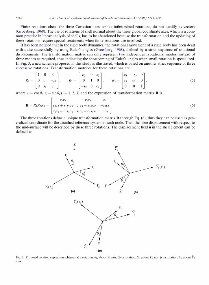
It has been noticed that in the rigid body dynamics, the rotational movement of a rigid body has been dealtwith quite successfully by using Euler�s angles (Groesberg, 1968), defined by a strict sequence of rotationaldisplacements. The transformation matrix can only represent two independent rotational modes, instead ofthree modes as required, thus indicating the shortcoming of Euler�s angles when small rotation is specialized.In Fig. 3, a new scheme proposed in this study is illustrated, which is based on another strict sequence of threesuccessive rotations. Transformation matrices for these rotations are
Fig. 3.axis.
R1 ¼1 0 0
0 c1 �s1
0 s1 c1
264375; R2 ¼
c2 0 s2
0 1 0
�s2 0 c2
264375; R3 ¼
c3 �s3 0
s3 c3 0
0 0 1
264375; ð5Þ
where ci = coshi, si = sinhi (i = 1, 2, 3) and the expression of transformation matrix R is
R ¼ R1R2R3 ¼c2c3 �c2s3 s2
c1s3 þ s1s2c3 c1c3 � s1s2s3 �s1c2
s1s3 � c1s2c3 s1c3 þ c1s2s3 c1c2
264375. ð6Þ
The three rotations define a unique transformation matrix R through Eq. (6); thus they can be used as gen-eralized coordinate for the attached reference system at each node. Then the fibre displacement with respect tothe mid-surface will be described by these three rotations. The displacement field u in the shell element can bedefined as
(a) (b)
(c)
Proposed rotation expression scheme: (a) a rotation, h1, about Y1 axis; (b) a rotation, h2, about Y 2 axis; (c) a rotation, h3, about eY 3
S.-C. Han et al. / International Journal of Solids and Structures 43 (2006) 5713–5735 5717
uðniÞ ¼X9
a¼1
NaðnbÞ �ua þ n3
ha
2bea
� �¼ �uðnbÞ þ n3�eðnbÞ; ð7Þ
where �u is the transitional displacement vector of a point in the mid-surface and beais the fibre displacement
vector at the node a, i.e.,
ea ¼ Ra bVa� bVa
. ð8Þ
Consequently, using Eq. (8), the displacement field in Eq. (7) can be expressed as
uðniÞ ¼X9
a¼1
NaðnbÞ �ua þ n3
ha
2ðRa � I3�3ÞbVa
� �; ð9Þ
where I3·3 is a unit matrix.
2.2. Incremental rotational and displacement vector
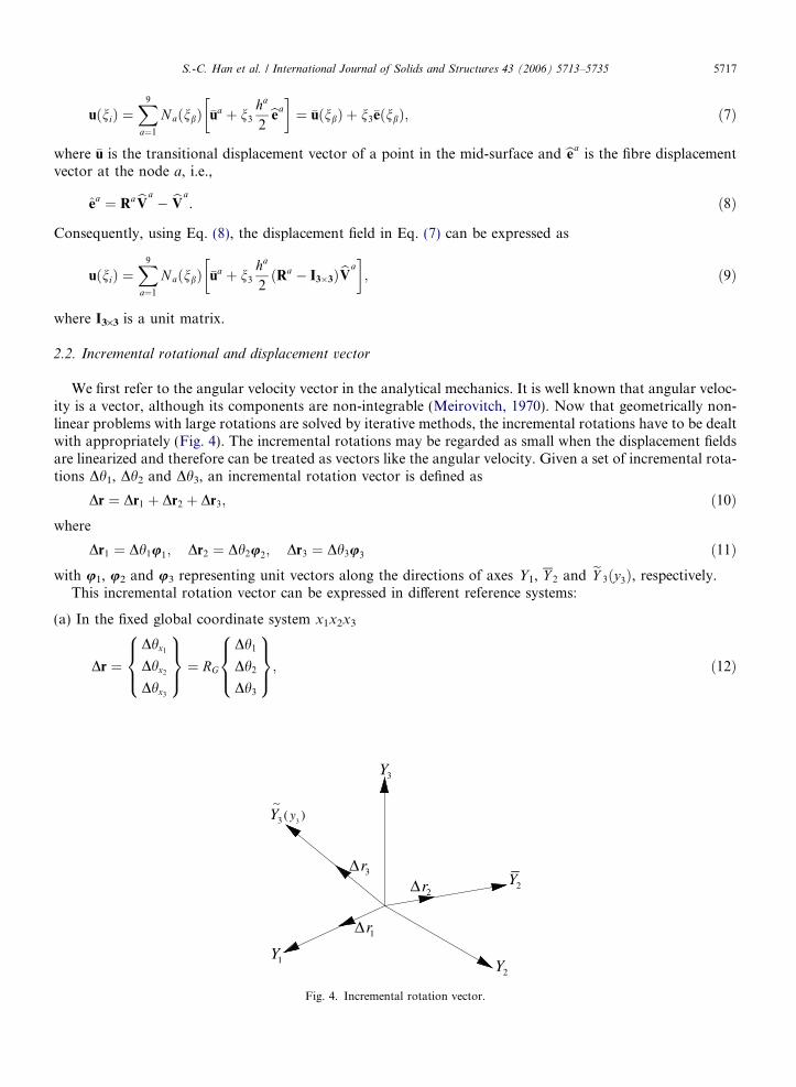
We first refer to the angular velocity vector in the analytical mechanics. It is well known that angular veloc-ity is a vector, although its components are non-integrable (Meirovitch, 1970). Now that geometrically non-linear problems with large rotations are solved by iterative methods, the incremental rotations have to be dealtwith appropriately (Fig. 4). The incremental rotations may be regarded as small when the displacement fieldsare linearized and therefore can be treated as vectors like the angular velocity. Given a set of incremental rota-tions Dh1, Dh2 and Dh3, an incremental rotation vector is defined as
Dr ¼ Dr1 þ Dr2 þ Dr3; ð10Þ
whereDr1 ¼ Dh1u1; Dr2 ¼ Dh2u2; Dr3 ¼ Dh3u3 ð11Þ
with u1, u2 and u3 representing unit vectors along the directions of axes Y1, Y 2 and eY 3ðy3Þ, respectively.This incremental rotation vector can be expressed in different reference systems:
(a) In the fixed global coordinate system x1x2x3
Dr ¼Dhx1
Dhx2
Dhx3
8><>:9>=>; ¼ RG
Dh1
Dh2
Dh3
8><>:9>=>;; ð12Þ
1Y2Y
3Y
2Y
33 ( )yY∼
1rΔ
2rΔ3rΔ
Fig. 4. Incremental rotation vector.
5718 S.-C. Han et al. / International Journal of Solids and Structures 43 (2006) 5713–5735
where
RG ¼1 0 s2
0 c1 �s1c2
0 s1 c1c2
264375. ð13Þ
(b) In the attached reference system y1y2y3
D�r ¼Dhy1
Dhy2
Dhy3
8><>:9>=>; ¼ RTDr ¼ RA
Dh1
Dh2
Dh3
8><>:9>=>;; ð14Þ
where
RA ¼ RTRG ¼c2c3 s3 0
�c2s3 c3 0
s2 0 1
264375. ð15Þ
For node a, the increment of the nodal fiber displacement in the attached reference system due to the incre-mental normal rotation D�ra, can be expressed as
DeaA ¼
n3ha
2
� �D�ra � bVa� �
¼ n3ha
2
� �Wa
D�r1
D�r2
D�r3
8><>:9>=>;
a
ð16Þ
in which
Wa ¼0 bV a
3 �bV a
2
�bV a
3 0 bV a
1bV a
2 �bV a
1 0
26643775. ð17Þ
Thus, the increment of nodal fiber displacement due to the incremental rotation of normal can be expressed inthe global reference system as
Deaðn3Þ ¼ RaDeaAðn3Þ ¼
n3ha
2
� �RaWaD�ra ð18Þ
which can be written in the form
Deaðn3Þ ¼ n3Ha
Dh1
Dh2
Dh3
8><>:9>=>;
a
; ð19Þ
where
Ha ¼ ha
2RaWaRa
A. ð20Þ
Let the nodal incremental displacement vector for node a be
DUa ¼ D�ua1;D�ua
2;D�ua3;Dha
1;Dha2;Dha
3
T. ð21Þ
The increment of nodal fiber displacement will be
Duaðn3Þ ¼ I3x3 n3Haj½ �DUa. ð22Þ
Then the incremental displacement field within the element can be expressed asDuðniÞ ¼X9
a¼1
NaðnbÞDuaðn3Þ ¼X9
a¼1
NaðnbÞ I3�3jn3Ha½ �DUa. ð23Þ
S.-C. Han et al. / International Journal of Solids and Structures 43 (2006) 5713–5735 5719
3. Torsional effect
As the element has no direct stiffness contribution to the drilling degree of freedom, the stiffness matrix maybe singular if neighboring elements are nearly co-plane. In the past, a fictitious torsional spring was addedeither locally at the element level, or in some pseudo-normal direction defined at each node. This techniqueoften is found unsatisfactory, especially for a flexible system in which an unrealistic amount of strain energyin the spring can be produced by a rigid body motion. In this study, based on the procedure proposed byKanok-Nukulchai (1979), the drilling degree of freedom will be tied to the in-plane twist by a penaltyfunctional through an additional strain energy as
Ut ¼ ktGZ
V eatðn1; n2Þ �
1
2
ow2
oz1
ðn1; n2; 0Þ �ow1
oz2
ðn1; n2; 0Þ� �� �2
dV ; ð24Þ
where kt is a parameter to be determined (the value of 0.1 is suggested); G is the shear modulus; Ve is the vol-ume of the element; at is the in-plane torsional rotation; w1 and w2 are displacement components in the localcoordinate system; zi (i = 1, 2, 3) are local Cartesian coordinates with z3 axis normal to the shell mid-surface;and dV is the volume element. A two-by-two Gauss integration scheme is applied for the evaluation of thetorsional stiffness in order to avoid the over-constrained situation.
4. Natural strain tensor
Following the natural co-ordinate system (Han et al., 2004), the natural strain tensor corresponding to theGreen strain tensor may be defined as
eEab ¼oPI
ona
oPJ
onbEIJ . ð25Þ
It should be noted that the Green strain tensor and the natural strain have the following tensor transfor-mation relationship
eEab ¼1
2
oPI
ona
ouI
onbþ ouJ
ona
oPJ
onb
� �. ð26Þ
The incremental membrane, bending and transverse shear strains with Eq. (26) can be separated into linearand nonlinear parts such as:
DeEm ¼ DLeEm þ DNLeEm; ð27aÞ
DeEb ¼ DLeEb þ DNLeEb; ð27bÞ
DeEs ¼ DLeEs þ DNLeEs. ð27cÞ
5. Strain energy and stress resultants of laminated plates
The strain energy U of the shell represented as a three-dimensional body is given by the expression, where incurvilinear coordinates the stress tensor Sij is contracted with the strain tensor Eij
U ¼ 1
2
ZV
SijEij dV . ð28Þ
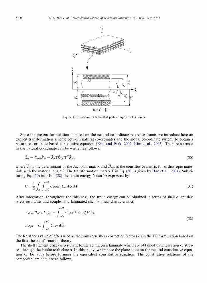
In the laminated structures, the stiffness properties are function of the normal coordinate. In Fig. 5, a cross-section of laminated plate composed of N layers is presented. A linear elastic properties of the anisotropic lay-ers are characterized by the tensor of elasticity Cijkl. In many applications, it can be assumed that calculationsof shell stiffness properties can be performed neglecting the differences in spatial and shell mid-surface metrics.In this case, the Hook�s law for each layer can be written by
Sij ¼ CijklEkl. ð29Þ
1ξ
h/2
h/2
ξ3
ξk-1ξ
h = ξ ξk 33
k k-1
3ξ3
k
ξ33
ξN -1N
2
ξ2ξ3
0ξ3
31
ξ3
ξ2
–
Fig. 5. Cross-section of laminated plate composed of N layers.
5720 S.-C. Han et al. / International Journal of Solids and Structures 43 (2006) 5713–5735
Since the present formulation is based on the natural co-ordinate reference frame, we introduce here anexplicit transformation scheme between natural co-ordinates and the global co-ordinate system, to obtain anatural co-ordinate based constitutive equation (Kim and Park, 2002; Kim et al., 2003). The stress tensorin the natural coordinate can be written as follows:
eS ij ¼ eCijkleEkl ¼ eJ 0TeDijklT
TeEkl; ð30Þ
where eJ 0 is the determinant of the Jacobian matrix and eDijkl is the constitutive matrix for orthotropic mate-rials with the material angle h. The transformation matrix T in Eq. (30) is given by Han et al. (2004). Substi-tuting Eq. (30) into Eq. (28) the strain energy U can be expressed by
U ¼ 1
2
ZA
Z h=2
�h=2
eCijkleEijeEkl dn3 dA. ð31Þ
After integration, throughout the thickness, the strain energy can be obtained in terms of shell quantities:stress resultants and couples and laminated shell stiffness characteristics
Aabcd;Babcd;Dabcd ¼Z h=2
�h=2
eCabcdð1; n3; n23Þdn3;
Aa3b3 ¼ ks
Z h=2
�h=2
eCa3b3 dn3.
ð32Þ
The Reissner�s value of 5/6 is used as the transverse shear correction factor (ks) in the FE formulation based onthe first shear deformation theory.
The shell element displays resultant forces acting on a laminate which are obtained by integration of stres-ses through the laminate thickness. In this study, we impose the plane state on the natural constitutive equa-tion of Eq. (30) before forming the equivalent constitutive equation. The constitutive relations of thecomposite laminate are as follows:
S.-C. Han et al. / International Journal of Solids and Structures 43 (2006) 5713–5735 5721
N ab
Mab
Qa3
8><>:9>=>; ¼
Aabcd Babcd 0
Babcd Dabcd 0
0 0 Aa3b3
264375
eEm
cdeEb
cdeEs
b3
8>><>>:9>>=>>;. ð33Þ
6. Transverse shear and membrane locking
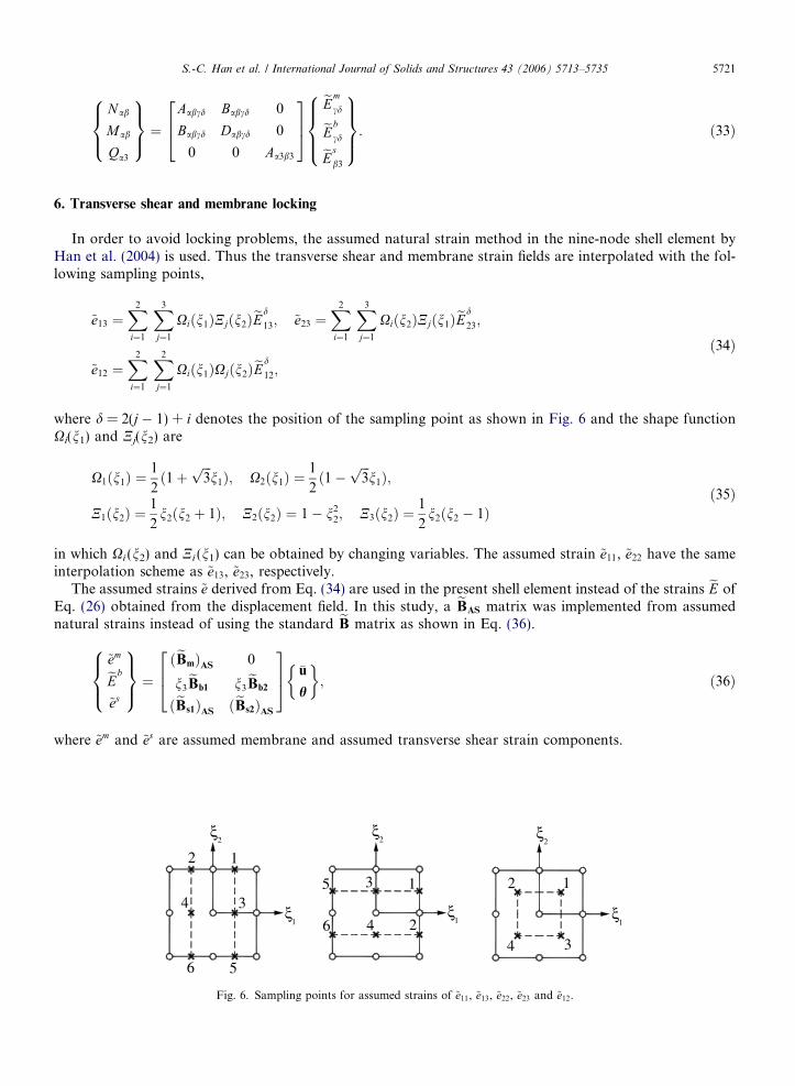
In order to avoid locking problems, the assumed natural strain method in the nine-node shell element byHan et al. (2004) is used. Thus the transverse shear and membrane strain fields are interpolated with the fol-lowing sampling points,
~e13 ¼X2
i¼1
X3
j¼1
Xiðn1ÞNjðn2ÞeEd
13; ~e23 ¼X2
i¼1
X3
j¼1
Xiðn2ÞNjðn1ÞeEd
23;
~e12 ¼X2
i¼1
X2
j¼1
Xiðn1ÞXjðn2ÞeEd
12;
ð34Þ
where d = 2(j � 1) + i denotes the position of the sampling point as shown in Fig. 6 and the shape functionXi(n1) and Nj(n2) are
X1ðn1Þ ¼1
2ð1þ
ffiffiffi3p
n1Þ; X2ðn1Þ ¼1
2ð1�
ffiffiffi3p
n1Þ;
N1ðn2Þ ¼1
2n2ðn2 þ 1Þ; N2ðn2Þ ¼ 1� n2
2; N3ðn2Þ ¼1
2n2ðn2 � 1Þ
ð35Þ
in which Xi (n2) and Ni (n1) can be obtained by changing variables. The assumed strain ~e11, ~e22 have the sameinterpolation scheme as ~e13, ~e23, respectively.
The assumed strains ~e derived from Eq. (34) are used in the present shell element instead of the strains eE ofEq. (26) obtained from the displacement field. In this study, a eBAS matrix was implemented from assumednatural strains instead of using the standard eB matrix as shown in Eq. (36).
~emeEb
~es
8><>:9>=>; ¼
ðeBmÞAS 0
n3eBb1 n3
eBb2
ðeBs1ÞAS ðeBs2ÞAS
264375 �u
h
� �; ð36Þ
where ~em and ~es are assumed membrane and assumed transverse shear strain components.
5
6
6 5
341
ξ
2 1
ξ2
3 1
24 1ξ
ξ2
12
4 3
1ξ
2ξ
Fig. 6. Sampling points for assumed strains of ~e11, ~e13, ~e22, ~e23 and ~e12.
5722 S.-C. Han et al. / International Journal of Solids and Structures 43 (2006) 5713–5735
7. Incremental equation of equilibrium
The generalized Hook�s law at large strain does not represent an approximate material behavior descriptionbecause stress-strain relation is non-linear. From the practical point of view, Hook�s law is only applicable tosmall strain, which constitutive tensor is constant coefficient. Using small strain assumption, the followingincremental equilibrium equation is obtained.
ZdðDLeEÞT eCDLeE dV þZ
SðDNLeEÞdV ¼ tþDtdW ext �Z
dðDLeEÞTSdV ; ð37Þ
where superscript t which is generally used as the current configuration is ignored in the above Eq. (37) andsuperscript t + Dt is the adjust incremented configuration, t+DtdWext is the external virtual work in t + Dt.
The total tangent stiffness comprises the material stiffness and the geometric stiffness. The linear part of theGreen strain tensor is used to derive the material stiffness matrix and non-linear part of the Green strain tensoris used to derive the geometric stiffness matrix.
7.1. Material stiffness matrix
If the strain-displacement Eq. (27) is substituted into Eq. (37), the linearized element material stiffness ma-trix (KL) is obtained.
ZdðDLeEÞT eCDLeE dV ¼ dDUT
Z eBT eCeB dV� �
DU ¼ dDUTKLDU. ð38Þ
For laminated composite structures, the stress resultant form which is called the equivalent constitutiveequations as derived in Eq. (33) are used to capture layer effect through the thickness direction. The elementstiffness matrix may be written in a matrix form using the equivalent constitutive equations. Finally the ele-ment stiffness matrix has 6 · 6 size on the reference-surface of shell element.
½KL� ¼Z
K11L K12
L
K21L K22
L
" #6�6
dA; ð39Þ
where the sub-matrix of [KL] is shown in Han et al. (2004).
7.2. Geometric stiffness matrix
In order to obtain an accurate geometric stiffness matrix, the stresses should be evaluated accurately. Theaccuracy of the computation of stresses for formulation of geometric stiffness matrix is maintained by obtain-ing the same interpolated strains in the computation of linear stiffness matrix. The stresses are computed at theintegration points based on these strains. Ignoring the second order term n2
3 in Eq. (27), the following relationis obtained.
fNLeEabg ¼
NLeE11
NLeE22
2NLeE12
2NLeE23
2NLeE13
8>>>>>><>>>>>>:
9>>>>>>=>>>>>>;¼ 1
2
ouI
on1
0 0
0ouI
on2
0
ouI
on2
ouI
on1
0
0ouI
on3
ouI
on2
ouI
on3
0ouI
on1
266666666666666664
377777777777777775
ouI
on1
ouI
on2
ouI
on3
266666664
377777775 ¼1
2QX. ð40Þ
S.-C. Han et al. / International Journal of Solids and Structures 43 (2006) 5713–5735 5723
The each component of displacement gradient can be expressed as follows:
ouI
on1
¼
ou1
on1
ou2
on1
ou3
on1
8>>>>>>>><>>>>>>>>:
9>>>>>>>>=>>>>>>>>;¼
o
on1
o
on1
o
on1
8>>>>>>>><>>>>>>>>:
9>>>>>>>>=>>>>>>>>;
�u1
�u2
�u3
8>><>>:9>>=>>;þ n3
o
on1
o
on1
0
8>>>>>><>>>>>>:
9>>>>>>=>>>>>>;�e1
�e2
�e3
8>><>>:9>>=>>; ¼ eG1�uI þ n3
eG2�eI . ð41Þ
Similarly the other terms are as follows:
ouI
on2
¼ eG3�uI þ n3eG4�eI ; ð42Þ
ouI
on3
¼ eG5�eI . ð43Þ
The incremental gradient displacement (X) for non-linear part with Eq. (27) is as follows:
DX ¼
oDu1
on1
oDu2
on1
oDu3
on1
8>>>>>>>><>>>>>>>>:
9>>>>>>>>=>>>>>>>>;¼
eG1 n3eG2eG3 n3eG4
0 eG5
26643775 DuI
DeI
( )¼ eG Du
Dh
( )¼ eGDU. ð44Þ
Then incremental variation of the non-linear part of Green strain is as follows:
dðDNLeEÞ ¼ dDQeGDU. ð45Þ
Substituting the non-linear part of strain into Eq. (37), the following geometric stiffness matrix is obtained.
ZSabdðDNLeEÞdV ¼ZdðDNLeEÞTSab dV ¼
ZdDXTDQTSab dV . ð46Þ
The geometric stiffness matrix in the natural coordinate is analytically integrated through the thickness. Bythe transformation the natural to the global frame, the element geometric stiffness matrix is obtained on theglobal frame with 6 · 6 sub-matrix.
½KG� ¼Z
K11G K12
G
K21G K22
G
" #6�6
dA; ð47Þ
where the sub-matrix of [KG] is shown in Han et al. (2004). Then the final assembled incremental non-linearequilibrium equation can be written is
ð½KL� þ ½KG�ÞDu ¼ tþDt �F� F; ð48Þ
where �F and F are the external and internal forces respectively.The equilibrium equation must be satisfied throughout the complete history of loading and the non-linearprocessing will be stopped only when the out of balance forces are negligible within a certain convergence lim-it. If it is necessary to extend the stability analysis beyond the limit point, i.e. in the so-called postbucklingrange, appropriate solution procedures must be applied. One approach is to use the arc-length control methodin conjunction with the Newton–Raphson method to extend the stability analysis beyond the limit point, byCrisfield (1981).
5724 S.-C. Han et al. / International Journal of Solids and Structures 43 (2006) 5713–5735
8. Numerical examples
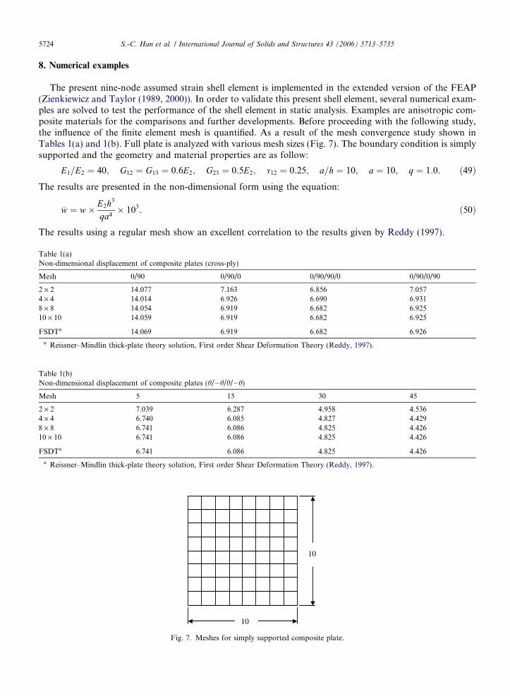
The present nine-node assumed strain shell element is implemented in the extended version of the FEAP(Zienkiewicz and Taylor (1989, 2000)). In order to validate this present shell element, several numerical exam-ples are solved to test the performance of the shell element in static analysis. Examples are anisotropic com-posite materials for the comparisons and further developments. Before proceeding with the following study,the influence of the finite element mesh is quantified. As a result of the mesh convergence study shown inTables 1(a) and 1(b). Full plate is analyzed with various mesh sizes (Fig. 7). The boundary condition is simplysupported and the geometry and material properties are as follow:
TableNon-d
Mesh
2 · 24 · 48 · 810 · 10
FSDT
a Re
TableNon-d
Mesh
2 · 24 · 48 · 810 · 10
FSDT
a Re
E1=E2 ¼ 40; G12 ¼ G13 ¼ 0:6E2; G23 ¼ 0:5E2; m12 ¼ 0:25; a=h ¼ 10; a ¼ 10; q ¼ 1:0. ð49Þ
The results are presented in the non-dimensional form using the equation:�w ¼ w� E2h3
qa4� 103. ð50Þ
The results using a regular mesh show an excellent correlation to the results given by Reddy (1997).
1(a)imensional displacement of composite plates (cross-ply)
0/90 0/90/0 0/90/90/0 0/90/0/90
14.077 7.163 6.856 7.05714.014 6.926 6.690 6.93114.054 6.919 6.682 6.92514.059 6.919 6.682 6.925
a 14.069 6.919 6.682 6.926
issner–Mindlin thick-plate theory solution, First order Shear Deformation Theory (Reddy, 1997).
1(b)imensional displacement of composite plates (h/�h/h/�h)
5 15 30 45
7.039 6.287 4.958 4.5366.740 6.085 4.827 4.4296.741 6.086 4.825 4.4266.741 6.086 4.825 4.426
a 6.741 6.086 4.825 4.426
issner–Mindlin thick-plate theory solution, First order Shear Deformation Theory (Reddy, 1997).
10
10
Fig. 7. Meshes for simply supported composite plate.
S.-C. Han et al. / International Journal of Solids and Structures 43 (2006) 5713–5735 5725
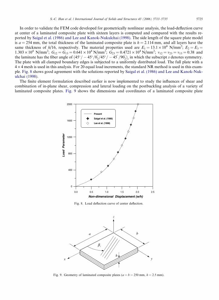
In order to validate the FEM code developed for geometrically nonlinear analysis, the load-deflection curveat center of a laminated composite plate with sixteen layers is computed and compared with the results re-ported by Saigal et al. (1986) and Lee and Kanok-Nukulchai (1998). The side length of the square plate modelis a = 254 mm, the total thickness of the laminated composite plate is h = 2.114 mm, and all layers have thesame thickness of h/16, respectively. The material properties used are E1 = 13.1 · 104 N/mm2; E2 = E3 =1.303 · 104 N/mm2; G12 = G13 = 0.641 · 104 N/mm2; G23 = 0.4721 · 104 N/mm2; m12 = m23 = m13 = 0.38 andthe laminate has the fiber angle of ð45�=� 45�=0
�
2=45�=� 45�=90
�
2Þs in which the subscript s denotes symmetry.The plate with all clamped boundary edges is subjected to a uniformly distributed load. The full plate with a4 · 4 mesh is used in this analysis. For 20 equal load increments, the standard NR method is used in this exam-ple. Fig. 8 shows good agreement with the solutions reported by Saigal et al. (1986) and Lee and Kanok-Nuk-ulchai (1998).
The finite element formulation described earlier is now implemented to study the influences of shear andcombination of in-plane shear, compression and lateral loading on the postbuckling analysis of a variety oflaminated composite plates. Fig. 9 shows the dimensions and coordinates of a laminated composite plate
0.0 0.5 1.0 1.5 2.0 2.5
Non-dimensional Displacement (w/h)
0
400
800
1200
1600
2000
Lo
ad P
aram
eter
Present
Saigal et al. (1986)
Lee et al. (1998)
Fig. 8. Load deflection curve of center deflection.
b
y
z
h
a
iβ
x
Fig. 9. Geometry of laminated composite plates (a = b = 250 mm, h = 2.5 mm).
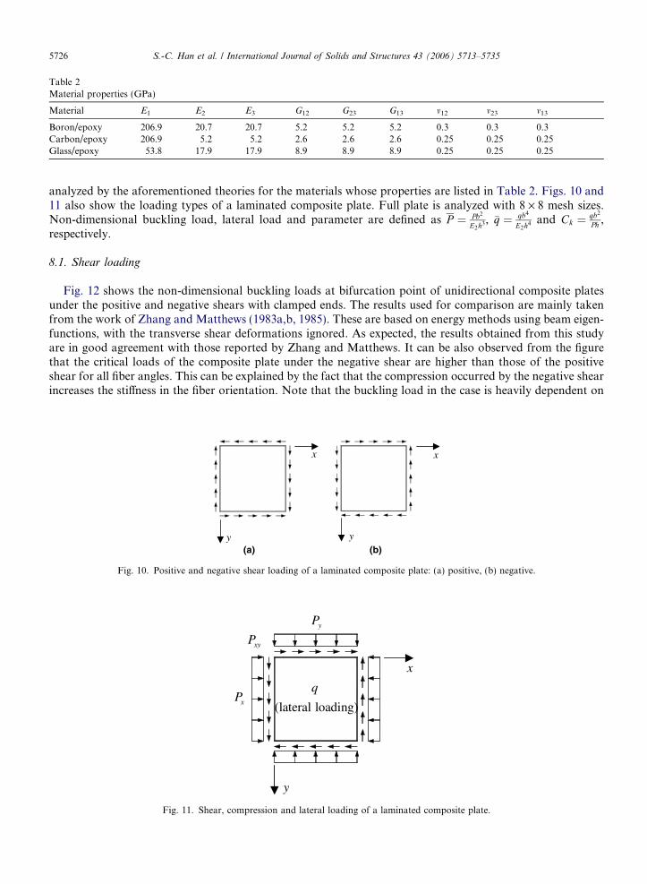
Table 2Material properties (GPa)
Material E1 E2 E3 G12 G23 G13 m12 m23 m13
Boron/epoxy 206.9 20.7 20.7 5.2 5.2 5.2 0.3 0.3 0.3Carbon/epoxy 206.9 5.2 5.2 2.6 2.6 2.6 0.25 0.25 0.25Glass/epoxy 53.8 17.9 17.9 8.9 8.9 8.9 0.25 0.25 0.25
5726 S.-C. Han et al. / International Journal of Solids and Structures 43 (2006) 5713–5735
analyzed by the aforementioned theories for the materials whose properties are listed in Table 2. Figs. 10 and11 also show the loading types of a laminated composite plate. Full plate is analyzed with 8 · 8 mesh sizes.Non-dimensional buckling load, lateral load and parameter are defined as P ¼ Pb2
E2h3, �q ¼ qb4
E2h4 and Ck ¼ qb2
Ph ,respectively.
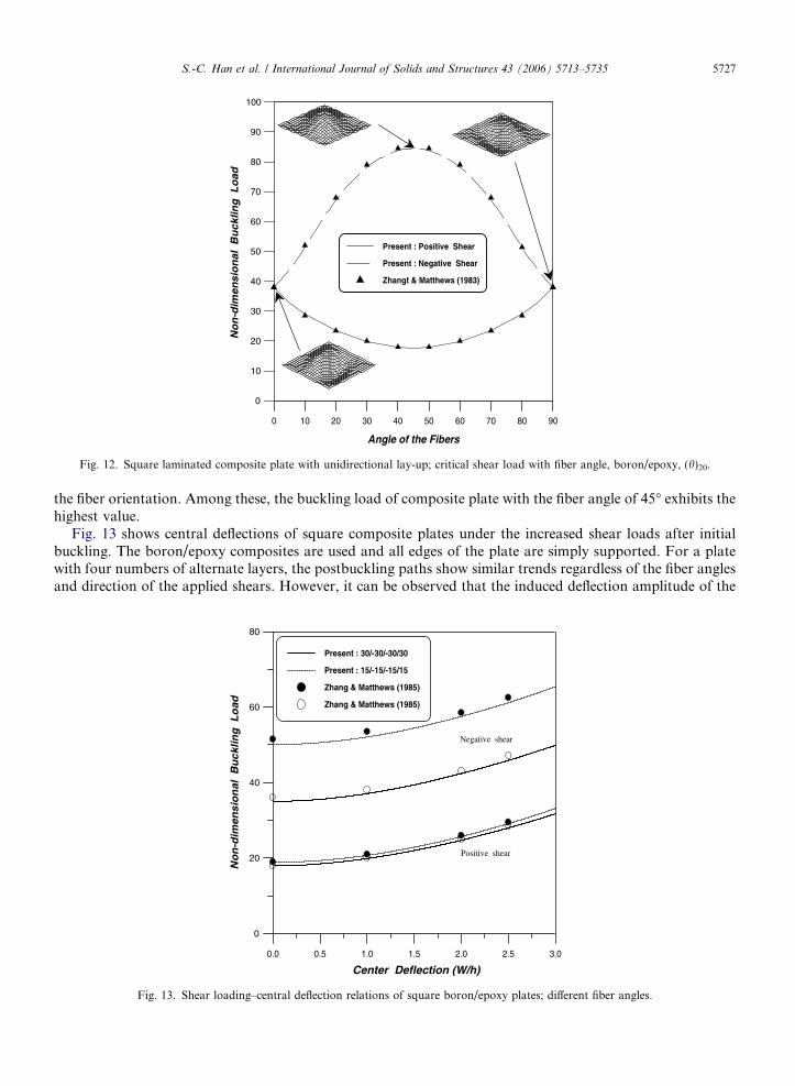
8.1. Shear loading
Fig. 12 shows the non-dimensional buckling loads at bifurcation point of unidirectional composite platesunder the positive and negative shears with clamped ends. The results used for comparison are mainly takenfrom the work of Zhang and Matthews (1983a,b, 1985). These are based on energy methods using beam eigen-functions, with the transverse shear deformations ignored. As expected, the results obtained from this studyare in good agreement with those reported by Zhang and Matthews. It can be also observed from the figurethat the critical loads of the composite plate under the negative shear are higher than those of the positiveshear for all fiber angles. This can be explained by the fact that the compression occurred by the negative shearincreases the stiffness in the fiber orientation. Note that the buckling load in the case is heavily dependent on
xx
yy(a) (b)
Fig. 10. Positive and negative shear loading of a laminated composite plate: (a) positive, (b) negative.
yP
xyP
x
(lateral loading)
qxP
y
Fig. 11. Shear, compression and lateral loading of a laminated composite plate.
0 10 20 30 40 50 60 70 80
Angle of the Fibers
90
Present : Positive Shear
Present : Negative Shear
Zhangt & Matthews (1983)
0
10
20
30
40
50
60
70
80
90
100
No
n-d
imen
sio
nal
Bu
cklin
g L
oad
Fig. 12. Square laminated composite plate with unidirectional lay-up; critical shear load with fiber angle, boron/epoxy, (h)20.
S.-C. Han et al. / International Journal of Solids and Structures 43 (2006) 5713–5735 5727
the fiber orientation. Among these, the buckling load of composite plate with the fiber angle of 45� exhibits thehighest value.
Fig. 13 shows central deflections of square composite plates under the increased shear loads after initialbuckling. The boron/epoxy composites are used and all edges of the plate are simply supported. For a platewith four numbers of alternate layers, the postbuckling paths show similar trends regardless of the fiber anglesand direction of the applied shears. However, it can be observed that the induced deflection amplitude of the
0.0 0.5 1.0 1.5 2.0 2.5 3.0
Center Deflection (W/h)
0
20
40
60
80
No
n-d
imen
sio
nal
Bu
cklin
g L
oad
Present : 30/-30/-30/30
Present : 15/-15/-15/15
Zhang & Matthews (1985)
Zhang & Matthews (1985)
Negative shear
Positive shear
Fig. 13. Shear loading–central deflection relations of square boron/epoxy plates; different fiber angles.
5728 S.-C. Han et al. / International Journal of Solids and Structures 43 (2006) 5713–5735
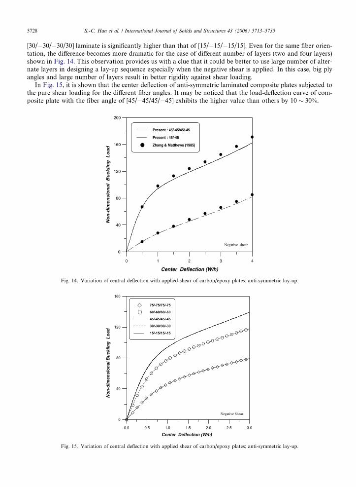
[30/�30/�30/30] laminate is significantly higher than that of [15/�15/�15/15]. Even for the same fiber orien-tation, the difference becomes more dramatic for the case of different number of layers (two and four layers)shown in Fig. 14. This observation provides us with a clue that it could be better to use large number of alter-nate layers in designing a lay-up sequence especially when the negative shear is applied. In this case, big plyangles and large number of layers result in better rigidity against shear loading.
In Fig. 15, it is shown that the center deflection of anti-symmetric laminated composite plates subjected tothe pure shear loading for the different fiber angles. It may be noticed that the load-deflection curve of com-posite plate with the fiber angle of [45/�45/45/�45] exhibits the higher value than others by 10 � 30%.
0 1 2 3 4
0
40
80
120
160
200
No
n-d
imen
sio
nal
Bu
cklin
g L
oad
Negative shear
Present : 45/-45/45/-45
Present : 45/-45
Zhang & Matthews (1985)
Center Deflection (W/h)
Fig. 14. Variation of central deflection with applied shear of carbon/epoxy plates; anti-symmetric lay-up.
0.0 0.5 1.0 1.5 2.0 2.5
Center Deflection (W/h)3.0
0
40
80
120
160
Non-
dim
ensi
onal
Buc
klin
g L
oad
75/-75/75/-75
60/-60/60/-60
45/-45/45/-45
30/-30/30/-30
15/-15/15/-15
Negative Shear
Fig. 15. Variation of central deflection with applied shear of carbon/epoxy plates; anti-symmetric lay-up.
S.-C. Han et al. / International Journal of Solids and Structures 43 (2006) 5713–5735 5729
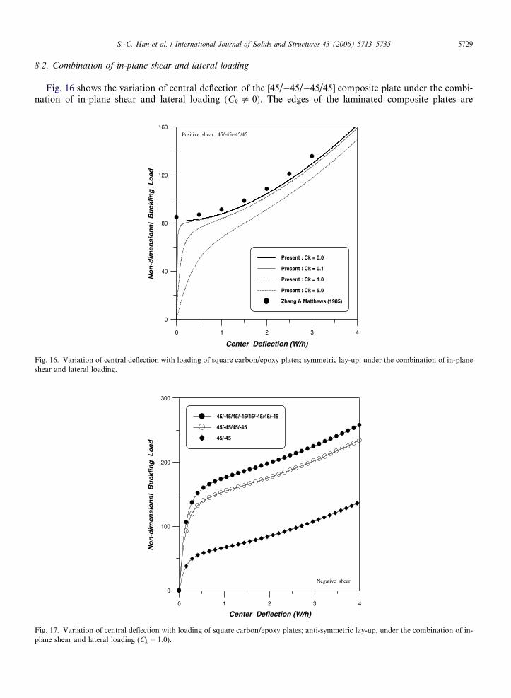
8.2. Combination of in-plane shear and lateral loading
Fig. 16 shows the variation of central deflection of the [45/�45/�45/45] composite plate under the combi-nation of in-plane shear and lateral loading (Ck 5 0). The edges of the laminated composite plates are
0 1 2 3 4
0
40
80
120
160
No
n-d
imen
sio
nal
Bu
cklin
g L
oad
Positive shear : 45/-45/-45/45
Present : Ck = 0.0
Present : Ck = 0.1
Present : Ck = 1.0
Present : Ck = 5.0
Zhang & Matthews (1985)
Center Deflection (W/h)
Fig. 16. Variation of central deflection with loading of square carbon/epoxy plates; symmetric lay-up, under the combination of in-planeshear and lateral loading.
0 1 2 3 4
0
100
200
300
No
n-d
imen
sio
nal
Bu
cklin
g L
oad
Negative shear
45/-45/45/-45/45/-45/45/-45
45/-45/45/-45
45/-45
Center Deflection (W/h)
Fig. 17. Variation of central deflection with loading of square carbon/epoxy plates; anti-symmetric lay-up, under the combination of in-plane shear and lateral loading (Ck = 1.0).
5730 S.-C. Han et al. / International Journal of Solids and Structures 43 (2006) 5713–5735
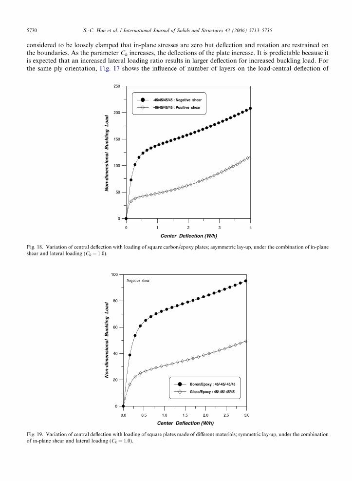
considered to be loosely clamped that in-plane stresses are zero but deflection and rotation are restrained onthe boundaries. As the parameter Ck increases, the deflections of the plate increase. It is predictable because itis expected that an increased lateral loading ratio results in larger deflection for increased buckling load. Forthe same ply orientation, Fig. 17 shows the influence of number of layers on the load-central deflection of
0 1 2 3 4
0
50
100
150
200
250
No
n-d
imen
sio
nal
Bu
cklin
g L
oad
-45/45/45/45 : Negative shear
-45/45/45/45 : Positive shear
Center Deflection (W/h)
Fig. 18. Variation of central deflection with loading of square carbon/epoxy plates; asymmetric lay-up, under the combination of in-planeshear and lateral loading (Ck = 1.0).
0.0 0.5 1.0 1.5 2.0 2.5 3.0
0
20
40
60
80
100
No
n-d
imen
sio
nal
Bu
cklin
g L
oad
Negative shear
Boron/Epoxy : 45/-45/-45/45
Glass/Epoxy : 45/-45/-45/45
Center Deflection (W/h)
Fig. 19. Variation of central deflection with loading of square plates made of different materials; symmetric lay-up, under the combinationof in-plane shear and lateral loading (Ck = 1.0).
S.-C. Han et al. / International Journal of Solids and Structures 43 (2006) 5713–5735 5731
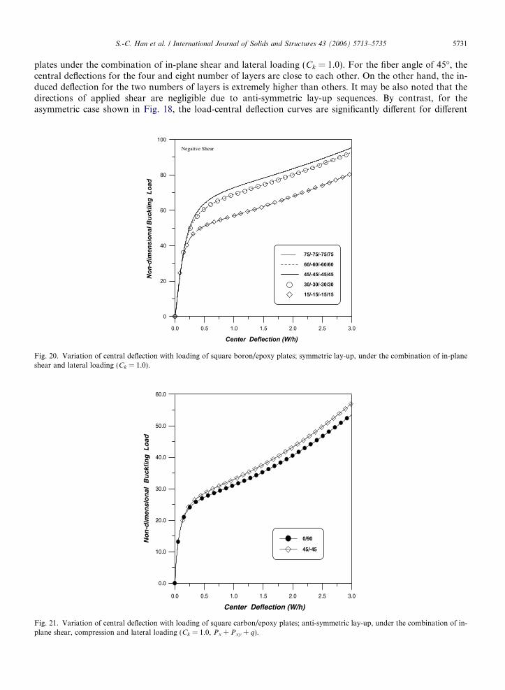
plates under the combination of in-plane shear and lateral loading (Ck = 1.0). For the fiber angle of 45�, thecentral deflections for the four and eight number of layers are close to each other. On the other hand, the in-duced deflection for the two numbers of layers is extremely higher than others. It may be also noted that thedirections of applied shear are negligible due to anti-symmetric lay-up sequences. By contrast, for theasymmetric case shown in Fig. 18, the load-central deflection curves are significantly different for different
0.0 0.5 1.0 1.5 2.0 2.5
Center Deflection (W/h)3.0
0
20
40
60
80
100No
n-di
men
sion
al B
uckl
ing
Loa
d
75/-75/-75/75
60/-60/-60/60
45/-45/-45/45
30/-30/-30/30
15/-15/-15/15
Negative Shear
Fig. 20. Variation of central deflection with loading of square boron/epoxy plates; symmetric lay-up, under the combination of in-planeshear and lateral loading (Ck = 1.0).
0.0 0.5 1.0 1.5 2.0 2.5 3.0
0.0
10.0
20.0
30.0
40.0
50.0
60.0
No
n-d
imen
sio
nal
Bu
cklin
g L
oad
0/90
45/-45
Center Deflection (W/h)
Fig. 21. Variation of central deflection with loading of square carbon/epoxy plates; anti-symmetric lay-up, under the combination of in-plane shear, compression and lateral loading (Ck = 1.0, Px + Pxy + q).
5732 S.-C. Han et al. / International Journal of Solids and Structures 43 (2006) 5713–5735
directions of the shear. Moreover, Fig. 19 shows the dramatic variation of central deflection with loading ofsquare symmetric laminates made of different materials (Boron/Epoxy and Glass/Epoxy). Fig. 20 shows thecenter deflection of symmetric laminated composite plates subjected to the in-plane shear and lateral loadingfor the different fiber angles. As expected, the load-deflection curve of composite plate with the fiber angle of
0.0 0.5 1.0 1.5 2.0 2.5 3.0
0
20
40
60
80
100
120
140
160
Non
-dim
ensi
onal
Buc
klin
g L
oad
0/90/0/90
45/-45/45/-45
90/0/0/90
45/-45/-45/45
Center Deflection (W/h)
Fig. 22. Variation of central deflection with loading of square carbon/epoxy plates; under the combination of in-plane shear, compressionand lateral loading (Ck = 1.0, Px + Pxy + q).
0.0 0.5 1.0 1.5 2.0 2.5 3.0
0
40
80
120
160
No
n-d
imen
sio
nal
Bu
cklin
g L
oad
Negative shear
45/-45/-45/45
45/-45/-45/45
45/-45/45/-45
Px+ Pxy+ q
Px+Py+ Pxy+ q
Px+Py+ Pxy+ q
Center Deflection (W/h)
Fig. 23. Variation of central deflection with loading of square carbon/epoxy plates; under the combination of in-plane shear, compressionand lateral loading (Ck = 1.0).
S.-C. Han et al. / International Journal of Solids and Structures 43 (2006) 5713–5735 5733
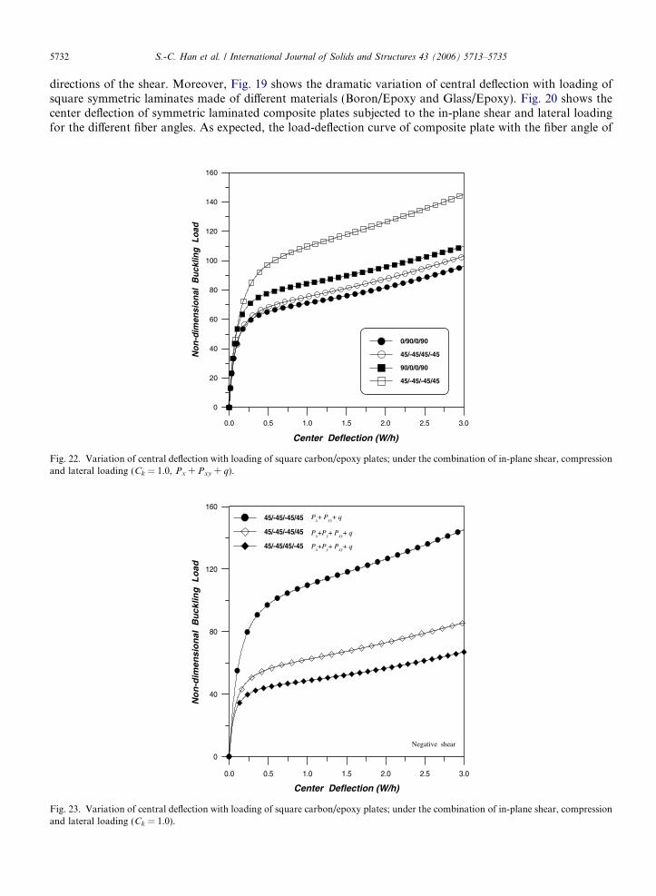
[45/�45/�45/45] exhibits the highest value. However, the difference decreases when compared with the case ofshear loading as shown in Fig. 15. From Fig. 21, we can also observe similar trend for the fiber angles of [0/90]and [45/�45]. From the observations, it may be noticed that the coupling effects of in-plane shear and lateralloading makes deleterious contributions to the buckling loads of composite plates for the different fiber angles.
Fig. 22 shows the difference of behaviors between anti-symmetric orthotropy and angle-ply laminatesmade of same material (Carbon/Epoxy). It can be observed from the figures that the buckling load of
0.0 0.5 1.0 1.5 2.0 2.5 3.0
0
20
40
60
80
100N
on-d
imen
sion
al B
uckl
ing
Loa
d
Px+ Py+ q
Px+Py+ Pxy+ q
Px+Py+ Pxy
Px+Py
Center Deflection (W/h)
Fig. 24. Variation of central deflection with loading of square carbon/epoxy plates; symmetric lay-up (45/�45/�45/45), under thecombination of in-plane shear, biaxial compression and lateral loading (Ck = 1.0).
0.0 0.5 1.0 1.5 2.0 2.5 3.0
0
20
40
60
80
100
Non
-dim
ensi
onal
Buc
klin
g L
oad
Negative Shear
No Shear
Positive Shear
Center Deflection (W/h)
Fig. 25. Variation of central deflection with loading of square carbon/epoxy plates; symmetric lay-up (45/�45/�45/45), under thecombination of in-plane shear, biaxial compression and lateral loading (Ck = 1.0, Px + Py + Pxy + q).
5734 S.-C. Han et al. / International Journal of Solids and Structures 43 (2006) 5713–5735
[45/�45/�45/45] laminate is higher than the others. We can also notice that the buckling load for angle-plylaminates is higher than that of orthotropic laminates. For the fiber angle of 45�, Fig. 23 shows buckling loadsof the plate subjected to action of in-plane compressive loads (Px and Py), shear load (Pxy), and lateral load(q). It can be also observed from the figures that the buckling load of [45/�45/�45/45] laminate is higher thanthe case of [45/�45/45/�45]. The parametric case studies reveal the importance of lay-up sequences for effi-cient and economic design of composite plates under the combined loading.
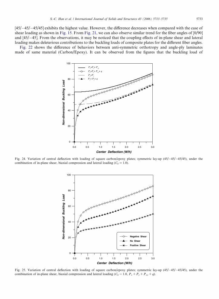
Figs. 24 and 25 show the buckling loads of [45/�45/�45/45] laminates subjected to different kinds of load-ing. The Fig. 24 shows how the deflection at the center of the plates varies with increasing shear and in-planecompressive loads after bifurcation point. Also, it can be seen that there are two postbuckling paths for eachplate when the lateral loads are included. In Fig. 25, the effect of the applied shear directions in the plate within-plane compressive and lateral loads is shown. These behaviors lead us to a conclusion that the influence ofapplied shear directions played a role in increasing or decreasing buckling loads.
9. Summary and conclusion
An intuitive prediction of the geometrically nonlinear behavior of laminated composite structures undercombined loads is difficult because of their complexity and the combined effect of anisotropy, nonlinear geom-etry, and load condition. In this study, the postbuckling characteristics are analyzed by considering variousparameters. The advanced finite element nonlinear analysis based on the Element-based Largrangian formu-lation shows the significance of stacking sequences and loading conditions for composite plates. From theparametric case studies, we find the following key observations in designing laminated composite structures.
1. The critical buckling loads of the composite plate under the negative shear are higher than those of the posi-tive shear for all fiber angles. The buckling load in the case is heavily dependent on the fiber orientation.For shear loading, it is desirable to use fiber angle of 45�.
2. Even for the same fiber orientation, the difference of buckling loads becomes more dramatic for the case ofdifferent number of layers. In this case, big ply angles and large number of layers result in better rigidityagainst shear loading.
3. For plates subjected to the pure shear loading and the combination of in-plane shear and lateral loading,the directions of applied shear are negligible due to anti-symmetric lay-up sequences. By contrast, for thesymmetric and the asymmetric case, the load-central deflection curves are significantly different for differentdirections of the shear.
4. We find that the buckling load for angle-ply laminates with fiber angle of 45� subjected to the combinedloading is higher than that of orthotropic laminates. However, it may be noted that the influence of thecombined loading on buckling loads for different fiber angles is smaller than that of single negative shearloading. In addition, the influence of applied shear directions increased or decreased the buckling loads oflaminated composite plates with the combination of in-plane shear, compression and lateral loading.
The results of this study may serve as benchmark for future guidelines in designing laminated compositeplates under the combination of in-plane shear, compression and lateral loading. But our parametric studyis only an example and more studies should be carried out for individual cases.
Acknowledgement
The authors would like to express our profound gratitude to Prof. W. Kanok-Nukulchai in AIT and Dr.K.D. Kim in Konkuk Univ., Korea for their encouragement while preparing this paper.
References
Ahmad, S., Irons, B.M., Zienkiewicz, O.C., 1970. Analysis of thick and thin shell structures by curved finite elements. InternationalJournal for Numerical Methods in Engineering 2, 419–451.
S.-C. Han et al. / International Journal of Solids and Structures 43 (2006) 5713–5735 5735
Belytschko, T., Wong, B.L., Stolarski, H., 1989. Assumed strain stabilization procedure for the 9-node lagrange shell element.International Journal for Numerical Methods in Engineering 28, 385–414.
Crisfield, M.A., 1981. A fast incremental/iterative solution procedures that handles snap-through. Computers and Structures 13, 55–62.Featherston, C.A., Watson, A., 2005. Buckling of optimized flat composite plates under shear and in-plane bending. Composites Science
and Technology 65 (6), 839–853.Featherston, C.A., 2003. Imperfection sensitivity of curved panels under combined compression and shear. International Journal of Non-
linear Mechanics 38 (2), 225–238.Groesberg, S.W., 1968. Advanced Mechanics. Wiley, New York.Han, S.C., Kim, K.D., Kanok-Nukulchai, W., 2004. An element-based 9-node resultant shell element for large deformation analysis of
laminated composite plates and shells. Structural Engineering and Mechanics, An International Journal 18 (6), 807–829.Huang, H.C., Hinton, E., 1986. A new nine node degenerated shell element with enhanced membrane and shear interpolation.
International Journal for Numerical Methods in Engineering 22, 73–92.Jang, J., Pinsky, P.M., 1987. An assumed covariant strain based 9-node shell element. International Journal for Numerical Methods in
Engineering 24, 2389–2411.Kanok-Nukulchai, W., 1979. A simple and efficient finite element for general shell analysis. International Journal for Numerical Methods
in Engineering 14, 179–200.Kim, K.D., Lomboy, G.R., Han, S.C., 2003. A co-rotational 8-node assumed strain shell element for postbuckling analysis of laminated
composite plates and shells. Computational Mechanics 30 (4), 330–342.Kim, K.D., Park, T.H., 2002. An 8-node Assumed Strain Element with Explicit Integration for Isotropic and Laminated Composite
Shells. Structural Engineering and Mechanics 13, 387–410.Kim, K.D., Voyiadjis, G.Z., 1999. Non-linear Finite Element Analysis of Composite Panels. Composites Part B: Engineering 30, 365–381.Lee, S.J., Kanok-Nukulchai, W., 1998. A Nine-Node Assumed Strain Finite Element for Large Deformation Analysis of Laminated
Shells. International Journal for Numerical Methods in Engineering 42, 777–798.Loughlan, J., 2001. The shear buckling behaviour of thin composite plates with particular reference to the effects of bend-twist coupling.
International Journal of Mechanical Sciences 43 (3), 771–792.Meirovitch, L., 1970. Methods of Analytical Dynamics. McGraw-Hill, NewYork.Reddy, J.N., 1997. Mechanics of Laminated Composite Plates. CRC Press, Florida.Saigal, S., Kapania, R.K., Yang, Y.T., 1986. Geometrically nonlinear finite element analysis of imperfect laminated shells. Journal of
Composite Materials 20, 197–214.Shufrin, I., Eisenberger, M., 2005. Stability and vibration of shear deformable plates-first order and higher order analyses. International
Journal of Solids and Structures 42, 1225–1251.Simo, J.C., Hughes, T.J.R., 1986. On the variational formulations of assumed strain methods. Journal of Applied Mechanics, ASME 53,
51–54.Wong, W.K., 1984. Pseudo Lagrangian Formulation for Large Deformation Analysis of Continua and Structures. Master Thesis, School
of Civil Engineering, A.I.T.Zhang, Y., Matthews, F.L., 1983a. Initial buckling of curved panels of generally layered composite materials. Composite Structures 1 (1),
3–30.Zhang, Y., Matthews, F.L., 1983b. Postbuckling behaviour of curved panels of generally layered composite materials. Composite
Structures 1 (2), 115–135.Zhang, Y., Matthews, F.L., 1985. Large deflection behavior of simply supported laminated panels under in-plane loading. Journal of
Applied Mechanics, ASME 52, 553–558.Zienkiewicz, O.C., Taylor, R.L., 1989. The Finite Element Method. McGraw-Hill, London.Zienkiewicz, O.C., Taylor, R.L., 2000. The Finite Element Method. Butterworth-Heinemann, London.