Embed Size (px)
Citation preview
1(2012) 1 – 13
Buckling analysis of laminated composite plates using an effi-cient C0 FE model
Abstract
Buckling analysis of laminated composite plates is carried
out by using an efficient C0 FE model developed based on
higher order zigzag theory. In this model the first derivatives
of transverse displacement have been treated as independent
variables to overcome the problem of C1 continuity associ-
ated with the FE implementation of the plate theory. The
C0 continuity of the present FE model is compensated in
the stiffness matrix calculations by using penalty parameter
approach. Numerical results and comparison with other ex-
isting solutions show that the present model is very efficient
in predicting the buckling responses of laminated compos-
ites.
Keywords
Buckling, laminated composites, Finite element analysis
S. K. Singh∗ and A. Chakrabarti
Department of Civil Engineering, Indian Insti-
tute of Technology, Roorkee-247 667, India
Ph.+91(1332)285844, Fax.+91(1332)275568
Received 10 Apr 2012;In revised form 23 Apr 2012
∗ Author email: [email protected]
1 INTRODUCTION
Laminated composite plates are widely used in civil infrastructure systems due to their high
strength to weight ratio and flexibility in design. One of the main failure mechanisms in
composite plates is buckling. Accurate prediction of structural response characteristics is a
challenging problem in the analysis of laminated composites due to the orthotropic structural
behavior, the presence of various types of couplings and due to less thickness of the structural
elements made of composites. Thus, an accurate buckling analysis of the laminated composite
plates is an important part of the structural design.
Finite element method has been widely used for the buckling analysis of laminated compos-
ite plates. To predict the buckling load of composite plates, a number of plate theories have
been proposed. The classical laminate plate theory (CLPT), which neglects the transverse
shear deformation effect, yields acceptable results only for thin laminates[32]. The structures
designed based on CLPT theory may be unsafe because the CLPT overestimates the buckling
load of the laminated composite plates. To take into account the effect of transverse shear
deformation, the first-order shear deformation theory (FSDT)[1, 28] has been used to predict
the dynamic response of laminated composite structures. In the first-order shear deforma-
tion theory (FSDT) a shear correction factor is used to compensate for the assumed uniform
transverse shear strain variations over the entire plate thickness. For a better representation
Latin American Journal of Solids and Structures 1(2012) 1 – 13
2 S. K. Singh∗ et al / Buckling analysis of laminated composite plates using an efficient C0 FE model
of the transverse shear deformations, various higher-order shear deformation (HSDT) plate
theories[5, 15, 16, 30, 36] were proposed. However, it has been observed and mentioned by
many researchers[3] that increasing the number of terms in the in-plane displacement compo-
nents does not improve the results and it is required to add the effect of inter-laminar transverse
shear stress continuity in a multilayered composite plate problem.
A major development in this direction is due to Di Sciuva[34], Murakami[23], Liu et al.[20],
and few others. They proposed zigzag plate theory where layer-wise theory is initially used
to represent the in-plane displacements having piecewise linear variation across the thickness.
The unknowns at the different interfaces are subsequently expressed in terms of those at the
reference plane through satisfaction of transverse shear stress continuity at the layer interfaces.
This theory is known as refined first order shear deformation theory (RFSDT). A further
improvement in this direction is due to Di Sciuva [35], Bhaskar et al.[2], Cho et al.[8, 16] and
some other investigators. They included the condition of zero transverse shear stress at top and
bottom of the plate in addition to the shear stress free conditions at the layer interfaces. This
theory is known as higher order zigzag theory (HZT) or refined higher order shear deformation
theory.
However, all these refined theories including the HSDT demand C1 continuity of the trans-
verse displacement along the element edges at the time of their finite element implementation.
However, a C1formulation is not encouraged in any practical applications. In this situation it
is highly required to develop a C0 finite element formulation which will overcome the above
C1continuity requirement of the theory (HZT).
Typically most of the C0 refined theories[18, 19, 40] en-force the mentioned continuity
assuming the displacement and transverse stresses as primary variable for multilayered com-
posite plates employing the FE method and showed a good agreement with three dimensional
elasticity solutions. On the other hand Ferreira et al. [39] combined the third order theory
of Reddy[11] with a meshfree method based on the multi-quadric radial basis function ap-
proach to study the behavior of multilayered laminated composite beams and plates. Mondal
et al. [29] analyzed the elastic stability behavior of simply supported anisotropic sandwich
flat panels subjected to mechanical in-plane loads by using an analytical approach. Shufrin et
al.[22] used a semi analytical approach for the buckling analysis of symmetrically laminated
rectangular plates with general boundary conditions. Ganapathi et al.[37] investigated the
free vibration characteristics of simply supported anisotropic composite laminates using an-
alytical approach. Nali et al.[14] analyzed buckling behaviour of laminated plates subjected
to combined biaxial/shear loading. Ferriera et al.[24] used meshfree method based on collo-
cation with radial basis functions for buckling and vibration analysis of laminated composite
plates. Ferriera et al.[12] used numerical method for the buckling analysis of laminated plates
based on collocation with wavelets. Nguyen-Van et al. [10] presented buckling and vibration
analysis of composite plate or shell structures of various shapes. Fiedler et al.[25] used refined
higher-order shear deformation theory for buckling analysis of multi-layered plates subjected
to unidirectional in-plane loads. Moreover, it has been also observed that in some cases the
violation of inter-laminar shear stress continuity might lead to higher buckling load.
Latin American Journal of Solids and Structures 1(2012) 1 – 13
S. K. Singh∗ et al / Buckling analysis of laminated composite plates using an efficient C0 FE model 3
In view of the above an efficient C0 FE model has been developed based on a higher
order zigzag theory (HZT) has been used to accurately predict the buckling load of laminated
composite plates. The C0continuity of the present finite element model has been compensated
in the stiffness matrix formulation by using penalty parameter approach. A nine noded C0
continuous isoparametric finite element has been used for the development of the proposed
finite element model. To assess the accuracy, numerical results obtained by using the proposed
finite element model based on HZT have been compared with the results of 3D elasticity, exact
and other finite element solutions available in the literature.
2 FORMULATION
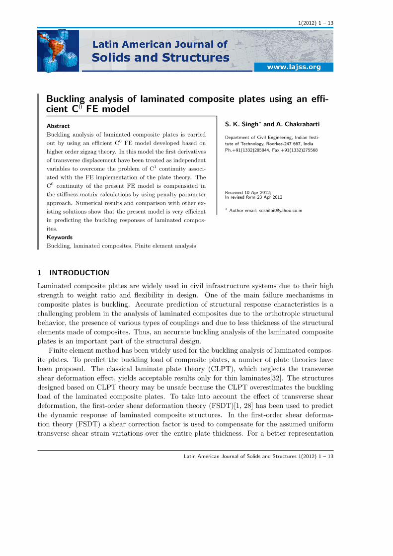
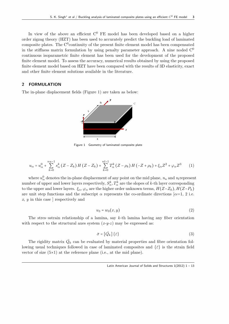
The in-plane displacement fields (Figure 1) are taken as below:
Figure 1 Geometry of laminated composite plate
uα = u0α +nu−1∑k=0
skα (Z −Zk)H (Z −Zk) +nl−1∑k=0
T kα (Z − ρk)H (−Z + ρk) + ξαZ2 + φαZ
3 (1)
where u0α denotes the in-plane displacement of any point on the mid plane, nu and nlrepresent
number of upper and lower layers respectively, Skα, T
kα are the slopes of k -th layer corresponding
to the upper and lower layers. ξα, φα are the higher order unknown terms, H(Z−Zk),H(Z−Pk)are unit step functions and the subscript α represents the co-ordinate directions [α=1, 2 i.e.
x, y in this case ] respectively and
u3 = w0(x, y) (2)
The stres–sstrain relationship of a lamina, say k -th lamina having any fiber orientation
with respect to the structural axes system (x-y-z ) may be expressed as:
σ = [Qk] {ε} (3)
The rigidity matrix Qk can be evaluated by material properties and fibre orientation fol-
lowing usual techniques followed in case of laminated composites and {ε} is the strain field
vector of size (5×1) at the reference plane (i.e., at the mid plane).
Latin American Journal of Solids and Structures 1(2012) 1 – 13
4 S. K. Singh∗ et al / Buckling analysis of laminated composite plates using an efficient C0 FE model
Now by utilizing the transverse shear stress free boundary conditions (σ3α∣z = ±h/2 = 0)at the top and bottom surface of the plate the components ξα and φα may be expressed as:
Φα = −4
3h2{w,α +
1
2(nu−1∑k=0
SKα +
nl−1
∑k=0
T kα)} (4)
and
ξα = −1
2h(nu−1∑k=0
Skα −
nl−1∑k=0
T kα) (5)
Similarly by imposing the transverse shear stress continuity conditions at the layer inter-
faces the following expressions for and are obtained:
Skα = akαγ(w,γ +Ψγ) + bkαγ w,γ (6)
T kα = ckαγ(w,γ +Ψγ) + dkαγ w,γ (7)
where, akαγ , bkαγ , c
kαγ , d
kαγ , are constants depending on material and geometric properties of
individual layers,W,γ is the derivatives of transverse displacement while γ = 1, 2 and S0α = ψα
is the rotation of normal at the mid plane about co-ordinate directions [α =1, 2 i.e., x, y in
this case].
By using equations (2 -7) the strain field vector can be evaluated as below,
{ε} = [H] {ε} (8)
where {ε} is the strain vector of size (17×1) at the reference plane (i.e., at the mid plane)
where is the matrix of size (5×17) containing z terms and some terms related to material
properties.
{ε}T =⎧⎪⎪⎨⎪⎪⎩
∂u01
∂x
∂u02
∂y
∂u02
∂x+ ∂u0
1
∂y∂w1
∂x∂w2
∂y∂w2
∂x∂w1
∂y∂Ψ1
∂x∂Ψ2
∂y∂Ψ2
∂x∂Ψ1
∂yΨ1 Ψ2
∂w∂x
∂w∂y
w1 w2
⎫⎪⎪⎬⎪⎪⎭(9)
In present formulation based on higher order zigzag theory the in-plane displacement fields
require C1 continuity of the transverse displacement for its finite element implementation. In
order to avoid the difficulties associated withC1continuity, the derivatives of w with respect to
x and y are expressed as follows.
∂w
∂x= w1 and
∂w
∂y= w2 (10)
which helps to define all the variables including and as C0 continuous.
For the present study, a nine noded C0 continuous isoparametric element shown in Figure
2 with seven nodal unknowns per node(u1, u2,w,Ψ1,Ψ2,w1,w2) are used to develop the finite
element formulation. The generalized displacements included in the present theory can be
expressed as follows.
Latin American Journal of Solids and Structures 1(2012) 1 – 13
S. K. Singh∗ et al / Buckling analysis of laminated composite plates using an efficient C0 FE model 5
u1 =9
∑i=1Niuiu2 =
9
∑i=1Nivi, u3 =
9
∑i=1Niui,Ψ1 =
9
∑i=1NiΨ1i ,
Ψ2 =∑9
i=1NiΨ2i w1 =∑9
i=1Niw1i w2 =∑9
i=1Niw2i
(11)
where Ni is the shape function for the nine noded isoparametric element[33].
Employing Hamilton’s principle, the dynamic equation of equilibrium for a finite element
can be formed. Accordingly the element stiffness matrix can be written as below
[Ke] =nu+nl∑i=1∭ [B]T [H]T [Qi] [H][B]dxdydz =
nu+nl∑i=1[B]T [D] [B]dxdy (12)
in which B is the strain matrix and Qi is the transformed material constant matrix. where
[D] =n
∑k=1∫ [H]T [Qi][H]dz
In a similar manner the geometric strain vector may be expressed as,
{εG} =
⎡⎢⎢⎢⎢⎢⎢⎢⎣
12(∂w∂x)2 + 1
2(∂u∂x)2 + 1
2(∂v∂x)2
12(∂w∂y)2+ 1
2(∂u∂y)2+ 1
2(∂v∂y)2
(∂w∂x) (∂w
∂y) + (∂u
∂x) (∂u
∂y) + (∂v
∂x) (∂v
∂y)
⎤⎥⎥⎥⎥⎥⎥⎥⎦
= 1
2
⎡⎢⎢⎢⎢⎢⎢⎣
∂w∂x
0 ∂u∂x
0 ∂v∂x
0
0 ∂w∂y
0 ∂u∂y
0 ∂v∂y
∂w∂y
∂w∂x
∂u∂y
∂u∂x
∂v∂y
∂v∂x
⎤⎥⎥⎥⎥⎥⎥⎦
⎧⎪⎪⎪⎪⎪⎪⎪⎪⎪⎪⎪⎨⎪⎪⎪⎪⎪⎪⎪⎪⎪⎪⎪⎩
∂w∂x∂w∂y∂u∂x∂u∂y∂v∂x∂v∂y
⎫⎪⎪⎪⎪⎪⎪⎪⎪⎪⎪⎪⎬⎪⎪⎪⎪⎪⎪⎪⎪⎪⎪⎪⎭(13)
= 1
2[AG][θ] =
1
2[AG][G][∆] (14)
With the matrix [G] in the above equation, the geometric stiffness matrix of an element can
be derived and may be written as
[kg] =nu+nl∑i=1∭ [G]T [Sk][G]dxdydz (15)
where [Sk] is the in-plane stress components of the k -th layer
Combining all the element geometric and elastic stiffness matrices, the dynamic equilibrium
equation can be written as
([K] − λ [KG]) {∂} = 0) (16)
in which [K] and [KG] are the global elastic and geometric stiffness matrix, where[∂] is the
mode shape vector of buckling and λ is the critical buckling load parameter respectively.
Latin American Journal of Solids and Structures 1(2012) 1 – 13
6 S. K. Singh∗ et al / Buckling analysis of laminated composite plates using an efficient C0 FE model
3 RESULTS AND DISCUSSION
In this section some problems on buckling of laminated composite plates are solved using the
present finite element model considering different features such as boundary conditions, ply
orientations, thickness ratio and aspect ratio. The results obtained by using the proposed FE
model based on HZT is first validated with some published results and then many new results
are also generated.
3.1 Simply supported square isotropic plates
In this example simply supported square isotropic (ν= 0.3) plate subjected to uni-axial loading
is considered. The analysis is carried out for different thickness ratio (a/h = 100, 10). The
critical buckling load obtained by using present FE model obtained are presented with the
results of Chakrabarti and Sheikh [6] based on refined higher order shear deformation theory
(RFSDT), Sundaresan et al. [38] based on first order shear deformation theory and that of
general purpose finite element program MARC [38] in Table 1. It is observed that the present
results are somewhat lesser than Chakrabarti and Sheikh [6], Sundaresan et al. [38] and
general purpose finite element program MARC [38]. It may be due to efficient modeling of the
transverse shear deformation followed in the present finite element model.
Table 1 Normalized Critical buckling loads (λcr) for square isotropic plate
Loading a/h Referencesuni-axial 100 Present(12×121)
Chakrabarti and Sheikh [6] 4.0Sundersan et al. [38] 4.0MARC [38] 4.0
10 Present(12×121) 3.768Chakrabarti and Sheikh [6] 3.782
λcr = λa2
π2D1 −Meshdivision
3.2 Cross-ply multilayered (0/90/..) composite plate simply supported at all the edges
In this example the buckling of a laminated (00/900/900/00) square composite plate is con-
sidered. The material properties of the individual layers are given by: E 1/E 2 = open, G12 =
G13 = 0.6E 2, G23 = 0.5E 2, ν12 =ν13 = 0.25.
This problem is solved to assess the performance of the proposed C0 finite element model.
The convergence and comparison of the normalized uni-axial critical buckling load obtained
by using the proposed element is shown in Table 2. The thickness ratio (a/h) is varied (100 to
5) to cover the range of very thin to thick plates. It is found that with refining meshes, results
obtained by the present FE model converge closely to the exact solution [26] and reasonably
close to the 3D elasticity solution given by Noor [13]. The present finite element model based
on higher order zigzag theory gives the more accurate results compared to the results given by
Latin American Journal of Solids and Structures 1(2012) 1 – 13
S. K. Singh∗ et al / Buckling analysis of laminated composite plates using an efficient C0 FE model 7
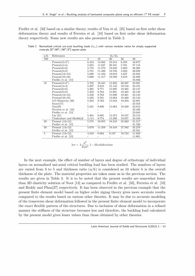
Fiedler et al. [33] based on a similar theory, results of Van et al. [25] based on first order shear
deformation theory and results of Ferreira et al. [10] based on first order shear deformation
theory respectively. Some new results are also presented in Table 2.
Table 2 Normalized critical uni-axial buckling loads (λcr) with various modular ratios for simply supportedcross-ply [00/900//900/00] square plate
a/h References E1/E2
100 3 10 20 30 40Present(2×21) 6.434 13.363 23.213 6.350 42.675Present(4×4) 5.855 11.837 20.331 5.781 37.118Present(6×6) 5.755 11.572 19.848 5.683 36.268Present(8×8) 5.721 11.486 19.702 5.650 36.039Present(12×12) 5.698 11.432 19.619 5.627 35.923Present(16×16) 5.690 11.417 19.599 5.619 35.898Fiedler et al. [13] - - - - 35.946
10 Present(2×21) 5.705 10.441 15.882 20.297 23.991Present(4×4) 5.297 9.810 15.143 19.516 23.191Present(6×6) 5.265 9.771 15.095 19.465 23.147Present(8×8) 5.259 9.764 15.091 19.465 23.138Present(12×12) 5.256 9.762 15.090 19.461 23.134Present(16×16) 5.256 9.761 15.064 19.460 23.1333-D Elasticity [26] 5.294 9.762 15.019 19.304 22.881Exact[17] - - - - 23.453Van[25] 5.321 9.809 15.064 19.339 22.912Ferreira et al. [10] - - - - 23.426Fiedler et al. [13] - - - - 23.043Liu [21] 5.401 9.985 15.374 19.537 23.154Chakrabart and Sheikh[4] 5.114 9.774 15.298 19.957 23.340
20 Present (12×12) 5.575 10.955 18.243 25.082 31.517Fiedler et al. [13] - - - 31.529
50 Present (12×12) 5.678 11.359 19.418 27.392 35.278Fiedler et al. [13] - - - - 35.321
5 Present (12×12) 4.310 6.904 9.197 10.724 11.858Fiedler et al. [13] - - - - 11.601
λcr = λa2
E2h31 −Meshdivision
In the next example, the effect of number of layers and degree of orthotropy of individual
layers on normalized uni-axial critical buckling load has been studied. The numbers of layers
are varied from 3 to 5 and thickness ratio (a/h) is considered as 10 where h is the overall
thickness of the plate. The material properties are taken same as in the previous section. The
results are given in Table 3. It is to be noted that the present results are somewhat lesser
than 3D elasticity solution of Noor [13] as compared to Fiedler et al. [33], Ferreira et al. [10]
and Reddy and Phan[27] respectively. It has been observed in the previous example that the
present finite element model based on higher order zigzag theory gives more accurate results
compared to the results based on various other theories. It may be due to accurate modeling
of the transverse shear deformation followed in the present finite element model to incorporate
the exact flexible pattern of the structures. Due to inclusion of shear deformation in a refined
manner the stiffness of the structure becomes less and therefore, the buckling load calculated
by the present model gives lesser values than those obtained by other theories.
Latin American Journal of Solids and Structures 1(2012) 1 – 13
8 S. K. Singh∗ et al / Buckling analysis of laminated composite plates using an efficient C0 FE model
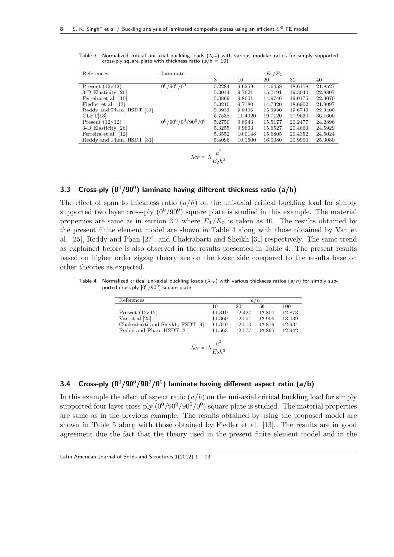
Table 3 Normalized critical uni-axial buckling loads (λcr) with various modular ratios for simply supportedcross-ply square plate with thickness ratio (a/h = 10)
References Laminate E1/E2
3 10 20 30 40Present (12×12) 00/900/00 5.2284 9.6259 14.6458 18.6158 21.85273-D Elasticity [26] 5.3044 9.7621 15.0191 19.3040 22.8807Ferreira et al. [10] 5.3869 9.8601 14.9746 19.0175 22.3070Fiedler et al. [13] 5.3210 9.7180 14.7320 18.6902 21.9097Reddy and Phan, HSDT [31] 5.3933 9.9406 15.2980 19.6740 22.3400CLPT[13] 5.7538 11.4920 19.7120 27.9630 36.1600Present (12×12) 00/900/00/900/00 5.2750 9.8943 15.5177 20.2477 24.28963-D Elasticity [26] 5.3255 9.9603 15.6527 20.4663 24.5929Ferreira et al. [12] 5.3552 10.0148 15.6805 20.4352 24.5024Reddy and Phan, HSDT [31] 5.4096 10.1500 16.0080 20.9990 25.3080
λcr = λa2
E2h3
3.3 Cross-ply (00/900) laminate having different thickness ratio (a/h)
The effect of span to thickness ratio (a/h) on the uni-axial critical buckling load for simply
supported two layer cross-ply (00/900) square plate is studied in this example. The material
properties are same as in section 3.2 where E 1/E 2 is taken as 40. The results obtained by
the present finite element model are shown in Table 4 along with those obtained by Van et
al. [25], Reddy and Phan [27], and Chakrabarti and Sheikh [31] respectively. The same trend
as explained before is also observed in the results presented in Table 4. The present results
based on higher order zigzag theory are on the lower side compared to the results base on
other theories as expected.
Table 4 Normalized critical uni-axial buckling loads (λcr) with various thickness ratios (a/h) for simply sup-ported cross-ply [00/900] square plate
References a/h10 20 50 100
Present (12×12) 11.310 12.427 12.800 12.873Van et al.[25] 11.360 12.551 12.906 13.039Chakrabarti and Sheikh, FSDT [4] 11.349 12.510 12.879 12.934Reddy and Phan, HSDT [31] 11.563 12.577 12.895 12.942
λcr = λa2
E2h3
3.4 Cross-ply (00/900/900/00) laminate having different aspect ratio (a/b)
In this example the effect of aspect ratio (a/b) on the uni-axial critical buckling load for simply
supported four layer cross-ply (00/900/900/00) square plate is studied. The material properties
are same as in the previous example. The results obtained by using the proposed model are
shown in Table 5 along with those obtained by Fiedler et al. [13]. The results are in good
agreement due the fact that the theory used in the present finite element model and in the
Latin American Journal of Solids and Structures 1(2012) 1 – 13
S. K. Singh∗ et al / Buckling analysis of laminated composite plates using an efficient C0 FE model 9
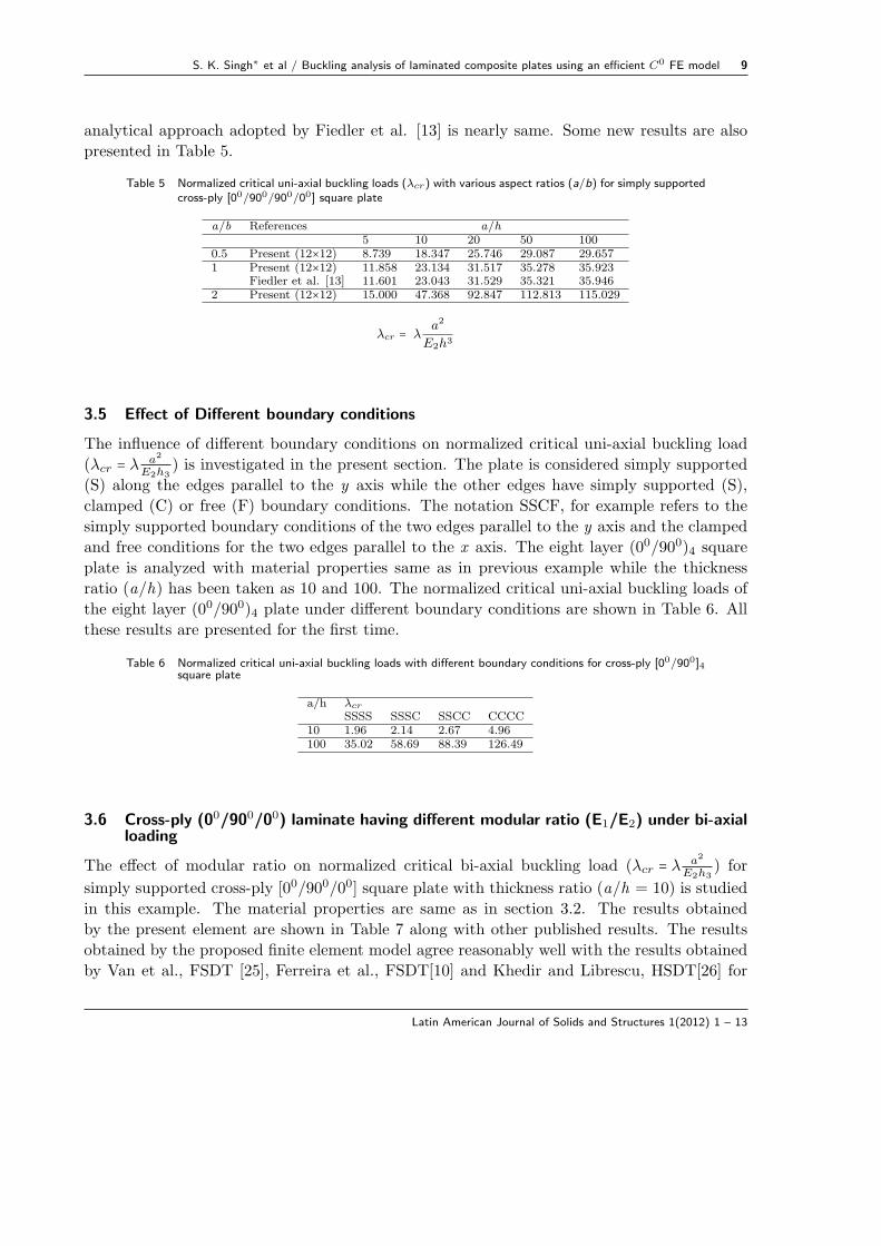
analytical approach adopted by Fiedler et al. [13] is nearly same. Some new results are also
presented in Table 5.
Table 5 Normalized critical uni-axial buckling loads (λcr) with various aspect ratios (a/b) for simply supportedcross-ply [00/900/900/00] square plate
a/b References a/h5 10 20 50 100
0.5 Present (12×12) 8.739 18.347 25.746 29.087 29.6571 Present (12×12) 11.858 23.134 31.517 35.278 35.923
Fiedler et al. [13] 11.601 23.043 31.529 35.321 35.9462 Present (12×12) 15.000 47.368 92.847 112.813 115.029
λcr = λa2
E2h3
3.5 Effect of Different boundary conditions
The influence of different boundary conditions on normalized critical uni-axial buckling load
(λcr = λ a2
E2h3) is investigated in the present section. The plate is considered simply supported
(S) along the edges parallel to the y axis while the other edges have simply supported (S),
clamped (C) or free (F) boundary conditions. The notation SSCF, for example refers to the
simply supported boundary conditions of the two edges parallel to the y axis and the clamped
and free conditions for the two edges parallel to the x axis. The eight layer (00/900)4 square
plate is analyzed with material properties same as in previous example while the thickness
ratio (a/h) has been taken as 10 and 100. The normalized critical uni-axial buckling loads of
the eight layer (00/900)4 plate under different boundary conditions are shown in Table 6. All
these results are presented for the first time.
Table 6 Normalized critical uni-axial buckling loads with different boundary conditions for cross-ply [00/900]4square plate
a/h λcr
SSSS SSSC SSCC CCCC10 1.96 2.14 2.67 4.96100 35.02 58.69 88.39 126.49
3.6 Cross-ply (00/900/00) laminate having different modular ratio (E1/E2) under bi-axialloading
The effect of modular ratio on normalized critical bi-axial buckling load (λcr = λ a2
E2h3) for
simply supported cross-ply [00/900/00] square plate with thickness ratio (a/h = 10) is studied
in this example. The material properties are same as in section 3.2. The results obtained
by the present element are shown in Table 7 along with other published results. The results
obtained by the proposed finite element model agree reasonably well with the results obtained
by Van et al., FSDT [25], Ferreira et al., FSDT[10] and Khedir and Librescu, HSDT[26] for
Latin American Journal of Solids and Structures 1(2012) 1 – 13
10 S. K. Singh∗ et al / Buckling analysis of laminated composite plates using an efficient C0 FE model
lower E 1/E 2 however with higher value of this ratio i.e., with increased orthotrpic behavior
the present results are on the lower side as expected and as explained earlier. No pre-buckling
state is considered since other results are also based on the same assumption.
Table 7 Normalized critical bi-axial buckling loads (λcr) with various modular ratios for simply supportedcross-ply [00/900/00] square plate with thickness ratio (a/h = 10)
References E1/E2
10 20 30 40Present (12×12) 4.812 7.320 8.688 9.784Van et al. [25] 4.939 7.488 9.016 10.252Ferreira et al. [10] - - - 10.196Fares and Zenkour [9] 4.963 7.588 8.575 10.202Exact [17] 4.963 5.516 9.056 10.259
λcr = λa2
E2h3
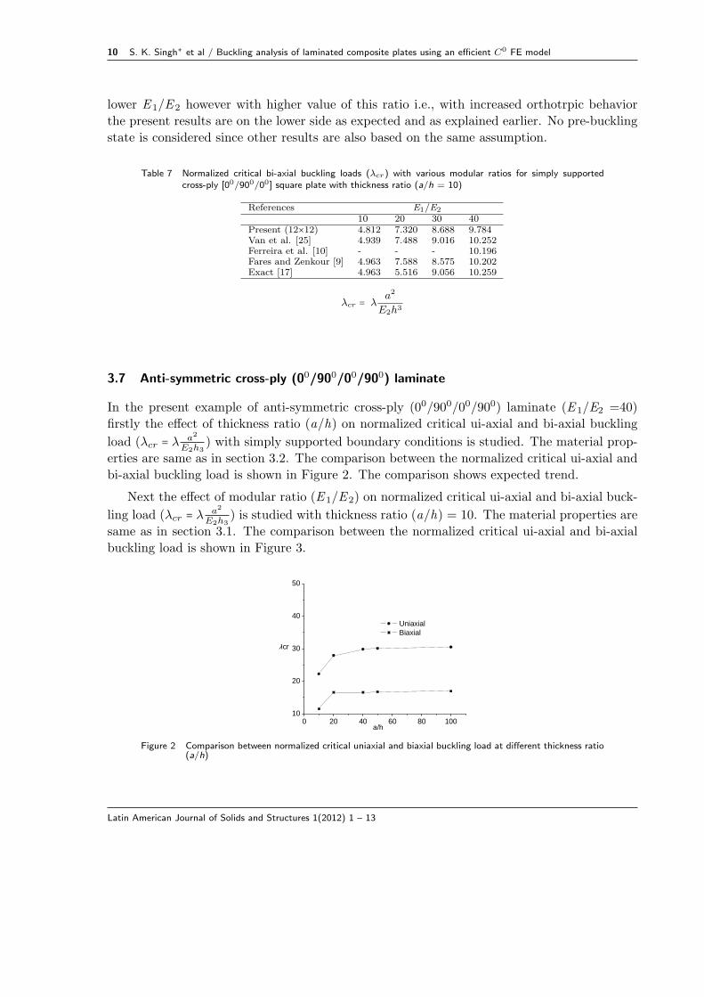
3.7 Anti-symmetric cross-ply (00/900/00/900) laminate
In the present example of anti-symmetric cross-ply (00/900/00/900) laminate (E 1/E2 =40)
firstly the effect of thickness ratio (a/h) on normalized critical ui-axial and bi-axial buckling
load (λcr = λ a2
E2h3) with simply supported boundary conditions is studied. The material prop-
erties are same as in section 3.2. The comparison between the normalized critical ui-axial and
bi-axial buckling load is shown in Figure 2. The comparison shows expected trend.
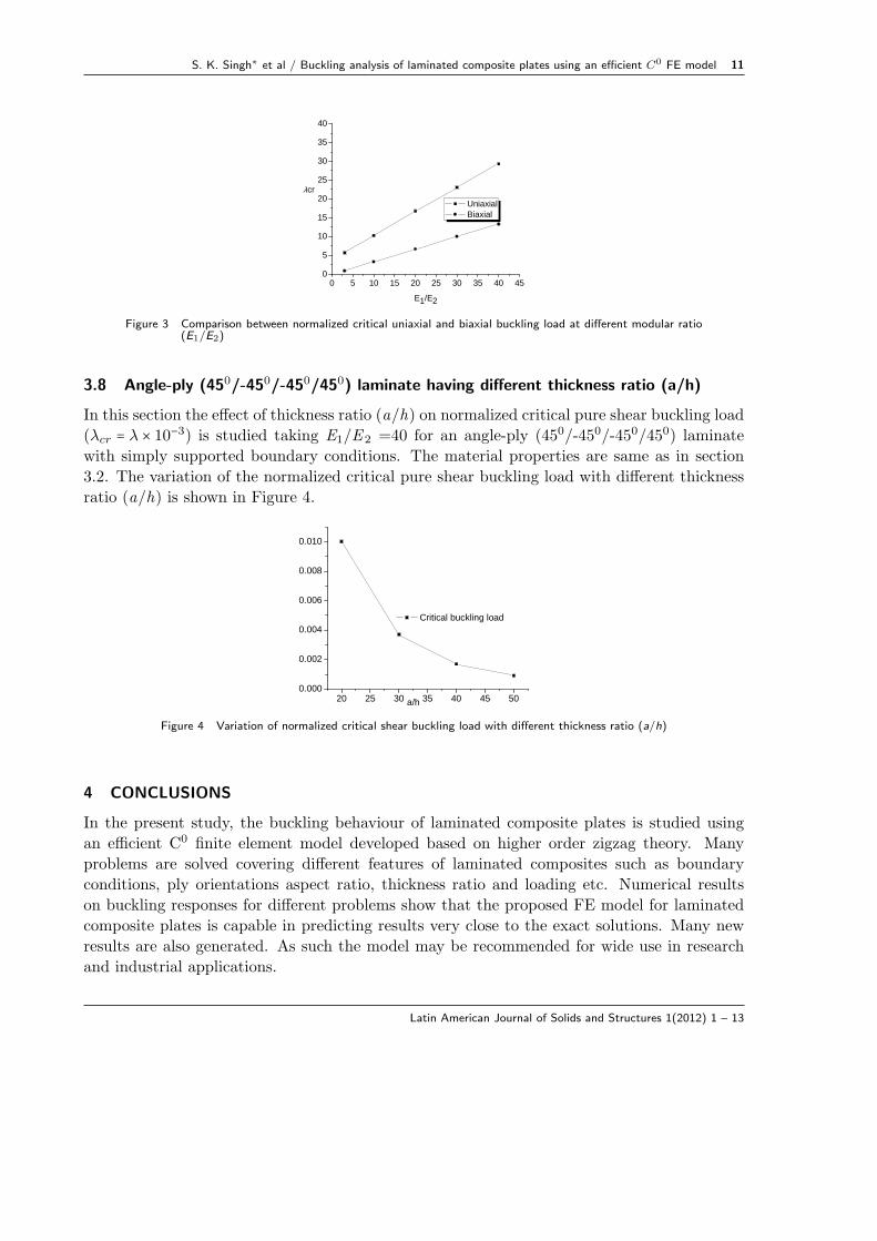
Next the effect of modular ratio (E 1/E 2) on normalized critical ui-axial and bi-axial buck-
ling load (λcr = λ a2
E2h3) is studied with thickness ratio (a/h) = 10. The material properties are
same as in section 3.1. The comparison between the normalized critical ui-axial and bi-axial
buckling load is shown in Figure 3.
0 20 40 60 80 10010
20
30
40
50
Uniaxial Biaxial
a/h
λcr
Figure 2 Comparison between normalized critical uniaxial and biaxial buckling load at different thickness ratio
(a/h)
Latin American Journal of Solids and Structures 1(2012) 1 – 13
S. K. Singh∗ et al / Buckling analysis of laminated composite plates using an efficient C0 FE model 11
0 5 10 15 20 25 30 35 40 450
5
10
15
20
25
30
35
40
Uniaxial Biaxial
E1/E2
λcr
Figure 3 Comparison between normalized critical uniaxial and biaxial buckling load at different modular ratio(E1/E2)
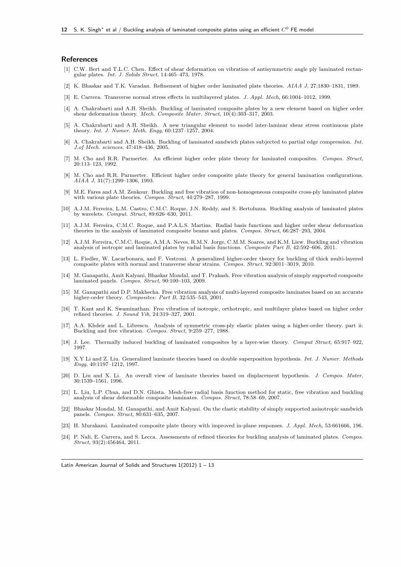
3.8 Angle-ply (450/-450/-450/450) laminate having different thickness ratio (a/h)
In this section the effect of thickness ratio (a/h) on normalized critical pure shear buckling load
(λcr = λ × 10−3) is studied taking E1/E 2 =40 for an angle-ply (450/-450/-450/450) laminate
with simply supported boundary conditions. The material properties are same as in section
3.2. The variation of the normalized critical pure shear buckling load with different thickness
ratio (a/h) is shown in Figure 4.
20 25 30 35 40 45 500.000
0.002
0.004
0.006
0.008
0.010
Critical buckling load
a/h
Figure 4 Variation of normalized critical shear buckling load with different thickness ratio (a/h)
4 CONCLUSIONS
In the present study, the buckling behaviour of laminated composite plates is studied using
an efficient C0 finite element model developed based on higher order zigzag theory. Many
problems are solved covering different features of laminated composites such as boundary
conditions, ply orientations aspect ratio, thickness ratio and loading etc. Numerical results
on buckling responses for different problems show that the proposed FE model for laminated
composite plates is capable in predicting results very close to the exact solutions. Many new
results are also generated. As such the model may be recommended for wide use in research
and industrial applications.
Latin American Journal of Solids and Structures 1(2012) 1 – 13
12 S. K. Singh∗ et al / Buckling analysis of laminated composite plates using an efficient C0 FE model
References[1] C.W. Bert and T.L.C. Chen. Effect of shear deformation on vibration of antisymmetric angle ply laminated rectan-
gular plates. Int. J. Solids Struct, 14:465–473, 1978.
[2] K. Bhaskar and T.K. Varadan. Refinement of higher order laminated plate theories. AIAA J, 27:1830–1831, 1989.
[3] E. Carrera. Transverse normal stress effects in multilayered plates. J. Appl. Mech, 66:1004–1012, 1999.
[4] A. Chakrabarti and A.H. Sheikh. Buckling of laminated composite plates by a new element based on higher ordershear deformation theory. Mech. Composite Mater. Struct, 10(4):303–317, 2003.
[5] A. Chakrabarti and A.H. Sheikh. A new triangular element to model inter-laminar shear stress continuous platetheory. Int. J. Numer. Meth. Engg, 60:1237–1257, 2004.
[6] A. Chakrabarti and A.H. Sheikh. Buckling of laminated sandwich plates subjected to partial edge compression. Int.J.of Mech. sciences, 47:418–436, 2005.
[7] M. Cho and R.R. Parmerter. An efficient higher order plate theory for laminated composites. Compos. Struct,20:113–123, 1992.
[8] M. Cho and R.R. Parmerter. Efficient higher order composite plate theory for general lamination configurations.AIAA J, 31(7):1299–1306, 1993.
[9] M.E. Fares and A.M. Zenkour. Buckling and free vibration of non-homogeneous composite cross-ply laminated plateswith various plate theories. Compos. Struct, 44:279–287, 1999.
[10] A.J.M. Ferreira, L.M. Castro, C.M.C. Roque, J.N. Reddy, and S. Bertoluzza. Buckling analysis of laminated platesby wavelets. Comput. Struct, 89:626–630, 2011.
[11] A.J.M. Ferreira, C.M.C. Roque, and P.A.L.S. Martins. Radial basis functions and higher order shear deformationtheories in the analysis of laminated composite beams and plates. Compos. Struct, 66:287–293, 2004.
[12] A.J.M. Ferreira, C.M.C. Roque, A.M.A. Neves, R.M.N. Jorge, C.M.M. Soares, and K.M. Liew. Buckling and vibrationanalysis of isotropic and laminated plates by radial basis functions. Composite Part B, 42:592–606, 2011.
[13] L. Fiedler, W. Lacarbonara, and F. Vestroni. A generalized higher-order theory for buckling of thick multi-layeredcomposite plates with normal and transverse shear strains. Compos. Struct, 92:3011–3019, 2010.
[14] M. Ganapathi, Amit Kalyani, Bhaskar Mondal, and T. Prakash. Free vibration analysis of simply supported compositelaminated panels. Compos. Struct, 90:100–103, 2009.
[15] M. Ganapathi and D.P. Makhecha. Free vibration analysis of multi-layered composite laminates based on an accuratehigher-order theory. Composites: Part B, 32:535–543, 2001.
[16] T. Kant and K. Swaminathan. Free vibration of isotropic, orthotropic, and multilayer plates based on higher orderrefined theories. J. Sound Vib, 24:319–327, 2001.
[17] A.A. Khdeir and L. Librescu. Analysis of symmetric cross-ply elastic plates using a higher-order theory. part ii:Buckling and free vibration. Compos. Struct, 9:259–277, 1988.
[18] J. Lee. Thermally induced buckling of laminated composites by a layer-wise theory. Comput Struct, 65:917–922,1997.
[19] X.Y Li and Z. Liu. Generalized laminate theories based on double superposition hypothesis. Int. J. Numer. MethodsEngg, 40:1197–1212, 1997.
[20] D. Liu and X. Li. An overall view of laminate theories based on displacement hypothesis. J. Compos. Mater,30:1539–1561, 1996.
[21] L. Liu, L.P. Chua, and D.N. Ghista. Mesh-free radial basis function method for static, free vibration and bucklinganalysis of shear deformable composite laminates. Compos. Struct, 78:58–69, 2007.
[22] Bhaskar Mondal, M. Ganapathi, and Amit Kalyani. On the elastic stability of simply supported anisotropic sandwichpanels. Compos. Struct, 80:631–635, 2007.
[23] H. Murakami. Laminated composite plate theory with improved in-plane responses. J. Appl. Mech, 53:661666, 196.
[24] P. Nali, E. Carrera, and S. Lecca. Assessments of refined theories for buckling analysis of laminated plates. Compos.Struct, 93(2):456464, 2011.
Latin American Journal of Solids and Structures 1(2012) 1 – 13
S. K. Singh∗ et al / Buckling analysis of laminated composite plates using an efficient C0 FE model 13
[25] H. Nguyen-Van, N. Mai-Duy, W. Karunasena, and T. Tran-Cong. Buckling and vibration analysis of laminatedcomposite plate/shell structures via a smoothed flat shell element with in-plane rotations. Compos. Struct, 89:612–625, 2011.
[26] A.K. Noor. Stability of multilayered composite plates. Fibre Sci. Technol, 8(2):81–89, 1975.
[27] N.D. Phan and J.N. Reddy. Analyses of laminated composite plates using a higher-order shear deformation theory.Int. J. Numer. Methods Engg, 21:2201–2219, 1985.
[28] J.N. Reddy. Free vibration of antisymmetric angle-ply laminated plates including transverse shear deformation bythe finite element method. J. Sound Vib, 4:565–576, 1979.
[29] J.N. Reddy. Cellular solids: structures & properties. CRC Press, Boca Raton, FL, 2nd ed edition, 2004.
[30] J.N Reddy and N.D. Phan. Stability and vibration of isotropic, orthotropic and laminated plates according to ahigher-order shear deformation theory. J. Sound Vib, 98:157–170, 1985.
[31] J.N. Reddy and N.D. Phan. Stability and vibration of isotropic, orthotropic and laminated plates according to ahigher-order shear deformation theory. J. Sound Vibr, 98(2):157–170, 1985.
[32] E. Reissner and Y. Stavasky. Bending and stretching of certain types of aelotropic elastic plates. J. Appl. Mech,28:402–408, 1961.
[33] D. Cook Robert, S. Malkus David, E. Michael Plesha, and J. Witt Robert. Concepts and Applications of FiniteElement Analysis. John Wiley & Sons Pte. Ltd, 4th edition edition, 2003.
[34] M. Di Sciuva. A refined transverse shear deformation theory for multilayered anisotropic plates. Atti. AcademiaScienze Torino, 118:279–295, 1984.
[35] M. Di Scuiva. Multilayered anisotropic plate models with continuous interlaminar stress. Comput. Struct,22(3):149167, 1992.
[36] A.H. Sheikh and A. Chakrabarti. A new plate bending element based on higher order shear deformation theory forthe analysis of composite plates. Finite Element Anal Des, 39:883–903, 2003.
[37] I. Shufrin, O. Rabinovitch, and M. Eisenberger. Buckling of symmetrically laminated rectangular plates with generalboundary conditions a semi analytical approach. Compos. Struct, 82:521–531, 2008.
[38] P. Sundaresan, G. Singh, and G.V. Rao. Buckling of moderately thick rectangular composite plates subjected topartial edge compression. International Journal of Mechanical Sciences, 40(11):1105–1117, 1998.
[39] W. Zhen and C. Wanji. Free vibration of laminated composite and sandwich plates using global-local higher-ordertheory. J. Sound Vib, 298:333–349, 2006.
[40] W. Zhen and C. Wanji. Buckling analysis of angle-ply composite and sandwich plates by combination of geometricstiffness matrix. Comput. Mech, 39:839–848, 2007.
Latin American Journal of Solids and Structures 1(2012) 1 – 13