Embed Size (px)
Citation preview
8/7/2019 Post Launch Memorandum Report for Mercury-Atlas No. 9(MA-9). Part 1 Mission Analysis
http://slidepdf.com/reader/full/post-launch-memorandum-report-for-mercury-atlas-no-9ma-9-part-1-mission 1/344
N o 23? Copies
(H1SA-TM-X-61634) E O S T L A O N C H M E M O R A N D U MH E F O B T F O B M E R C U R Y - A T I A S N O . 9 ( H A - 9 ) . P A R T1 : M I S S I O N A N A L Y S I S ( N A S A ) 3 5 0 p
n o /
P O S T L A U N C H M E M O R A N D U M R E P O R T
F O R
M E R C U R Y - A T L A S N O . 9 (MA-9)(L0
PART I - MISSION ANALYSIS
|intervals; declassified
N A T I O N A L A E R O N A U T I C S A ND S P A C E A D M I N
M A N N E D S P A C E C R A F T C E N T E R
Cape Canaveral, Florida
June 2k, 1963
nent contains information affecting the national defense of the~MiHlMii. |-
I VJ • \J i *** » f
contents
8/7/2019 Post Launch Memorandum Report for Mercury-Atlas No. 9(MA-9). Part 1 Mission Analysis
http://slidepdf.com/reader/full/post-launch-memorandum-report-for-mercury-atlas-no-9ma-9-part-1-mission 2/344
POSTLAUNCH MEMORANDUM REPORT
FOR
MERCURY-ATLAS NO. 9 (MA-9)
PART I - MISSION ANALYSIS
Idited By: J. H. Boynton, Senior Editor
v R. G. Arbic
^C. A. Berry, M.D.
rfR. E. Day
P. C. Donnelly
,,W. R. Kelly
J. P. Mayer
^A. B. Shepard
R . E. Smylie
rt C M Scr t cS .H
O >s fl r-l 0
E H pq0o m
NATIONAL AERONAUTICS AND SPACE ADMINISTRATION
MANNED SPACECRAFT CENTER
Cape Canaveral, Florida
June 2k, 1963
8/7/2019 Post Launch Memorandum Report for Mercury-Atlas No. 9(MA-9). Part 1 Mission Analysis
http://slidepdf.com/reader/full/post-launch-memorandum-report-for-mercury-atlas-no-9ma-9-part-1-mission 3/344
TABLE OF CONTENTS
Section Page
1.0 MISSION SUMMARY 1-1
2.0 INTRODUCTION 2-1
3.0 SPACE VEHICLE DESCRIPTION 3-1
3.1 Spacecraft Description 3-1
3.2 Launch-Vehicle Description 3 - 1 5
I j - . O TRAJECTORY AND MISSION EVENTS U - 1
U.I Sequence of Flight Events U-l
U.2 Flight Trajectory U-3
5.0 SPACECRAFT PERFORMANCE 5-1
5.1 Spacecraft Control System 5-1
5.2 Life Support Systems 5-7
5-3 Communications Systems 5 - 2 75.U Mechanical and Pyrotechnic Systems 5 - 2 85-5 Electrical and Sequential Systems 5 - 3 05.6 Instrumentation System 5- 33
5.7 Heat Protection System 5 - 3^
5.8 Scientific Experiments 5 - 3 8
6.0 LAUNCH-VEHICLE PERFORMANCE 6-1
6.1 Airframe 6-16.2 Propulsion System 6-1
6.3 Propellant Tanking 6-2
6.U Propellant Utilization 6-2
6.5 Pneumatics ' . . . . 6-2
6.6 Electrical System 6-3
6.7 Flight Control System 6-3
6.8 Guidance 6-U
6.9 Abort Sensing and Implementation System 6-5
7.0 ASTRONAUT ACTIVITIES 7-1
7-1 Aeromedical Analysis 7-1
7.2 Pilot's Performance 7 - U-2
7.3 Pilot's Flight Report 7 - 7U
8.0 FLIGHT CONTROL AND NETWORK PERFORMANCE 8-1
8.1 Flight Control Summary 8-1
8.2 Mercury Network Performance 8 - 1 2
8/7/2019 Post Launch Memorandum Report for Mercury-Atlas No. 9(MA-9). Part 1 Mission Analysis
http://slidepdf.com/reader/full/post-launch-memorandum-report-for-mercury-atlas-no-9ma-9-part-1-mission 4/344
9.0 RECOVERY 9-1
9.1 Recovery Plans 9-1
9.2 Recovery Operations 9-2
9-3 Recovery Aids 9-3
0.0 APPENDIX A 10-1
10.1 Spacecraft History 10-1
10.2 Launch Procedure 10-6
10.3 Weather Conditions 10-7
10 A Flight Safety Review 10-9
10.5 Photographic Coverage 10-11
10.6 Postflight Inspection 10-11+
11.0 A P P E T O I X B - A C K W O W L E D G E M E E T 11-1
8/7/2019 Post Launch Memorandum Report for Mercury-Atlas No. 9(MA-9). Part 1 Mission Analysis
http://slidepdf.com/reader/full/post-launch-memorandum-report-for-mercury-atlas-no-9ma-9-part-1-mission 5/344
I
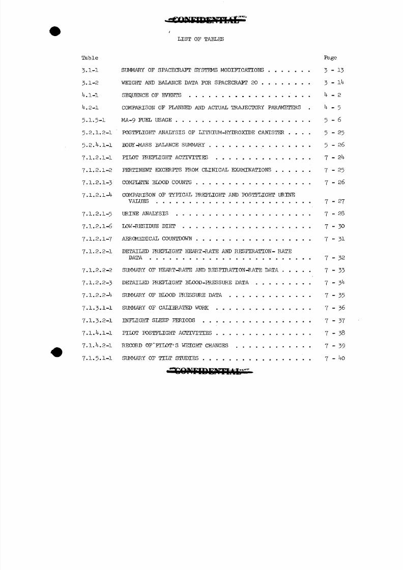
LIST O F T A B L E S
Table Page
3.1-1 SUMMARY OF SPACECRAFT SYSTEMS MODIFICATIONS 3-13
3.1-2 WEIGHT AND BALANCE DATA FOR SPACECRAFT 20 3 - l4
4.1-1 SEQUENCE OF EVENTS . . 4-2
4.2-1 COMPARISON OF PLANNED AND ACTUAL TRAJECTORY PARAMETERS . 4-5
5.1.5-1 MA-9FUEL USAGE 5-6
5.2.1.2-1 POSTFLIGHT ANALYSIS OF LITHIUM-HYDROXIDE CANISTER .... 5-25
5.2.4.1-1 BODY-MASS BALANCE SUMMARY 5-26
7.1.2.1-1 PILOT PREFLIGHT ACTIVITIES 7-24
7.1.2.1-2 PERTINENT EXCERPTS FROM CLINICAL EXAMINATIONS 7-25
7.1.2.1-3 COMPLETE BLOOD COUNTS 7-26
7.1.2.1-4 COMPARISON OF TYPICAL PREFLIGHT AND POSTFLIGHT URINE
VALUES 7-27
7.1.2.1-5 U R I N E A N A L Y S I S 7-28
7.1.2.1-6 L O W - R E S I D U E DIET 7-30
7.1.2.1-7 A E R O M E D I C A L C O U N T D O W N 7-31
7.1.2.2-1 D E T A I L E D P R E F L I G H T H E A R T - R A T E A N D RESPIRATION- R A T E
DATA 7-32
7.1.2.2-2 S U M M A R Y O F H E A R T - R A T E A N D R E S P I R A T I O N - R A T E DATA 7-3
7.1.2.2-3 D E T A I L E D P R E F L I G H T B L O O D - P R E S S U R E DATA 7 - 3 4
7.1.2.2-4 S U M M A R Y O F B L O O D P R E S S U R E DATA 7-35
7.1.3.1-1 S U M M A R Y OF C A L I B R A T E D W O R K 7-36
7.1.3.2-1 INFLIGHT SLEEP P E R I O D S 7-37
7.1.4.1-1 PILOT P O S T F L I G H T ACTIVITIES 7-38
7.1.4.2-1 R E C O R D OF'PILOT'S W E I G H T CHANGES 7-39
7.1.5.1-1 S U M M A R Y OFTILT S T U D I E S . 7 - 40
8/7/2019 Post Launch Memorandum Report for Mercury-Atlas No. 9(MA-9). Part 1 Mission Analysis
http://slidepdf.com/reader/full/post-launch-memorandum-report-for-mercury-atlas-no-9ma-9-part-1-mission 6/344
•GOIinDDMlAL •
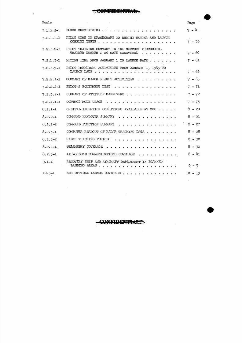
Table Page
7.1.5.3-! BLOOD CHEMISTRIES 7 - 4l
7.2.1.1-1 PILOT TIME IN SPACECRAFT 20 DURING HANGAR AND LAUNCH
COMPLEX TESTS 7-59
7.2.1.2-1 PILOT TRAINING SUMMARY IN THE MERCURY PROCEDURES
TRAINER NUMBER 2 AT CAPE CANAVERAL 7 - 60
7.2.1.3-1 FLYING TIME FROM JANUARY 1 TO LAUNCH DATE 7 - 6l
7.2.1.5-1 PILOT PREFLIGHT ACTIVITIES FROM JANUARY 1, 1963 TO
LAUNCH DATE 7-62
7.2.2.1-1 SUMMARY OF MAJOR FLIGHT ACTIVITIES 7-65
7.2.2.2-1 PILOT'S EQUIPMENT LIST 7-71
7.2.3.2-1 SUMMARY OF ATTITUDE MANEUVERS 7-72
7.2.4.1-1 CONTROL MODE USAGE 7-73
8.2.1-1 ORBITAL INSERTION CONDITIONS AVAILABLE AT MCC 8-20
8.2.2-1 COMMAND HANDOVER SUMMARY 8-21
8.2.2-2 COMMAND FUNCTION SUMMARY 8-27
8.2.3-1 COMPUTER READOUT OF RADAR TRACKING DATA 8-28
8.2.3-2 RADAR TRACKING PERIODS 8-30
8.2.4-1 TELEMETRY COVERAGE 8-32
8.2.5-1 AIR-43ROUND COMMUNICATIONS COVERAGE 8 - 4l
9.1-1 RECOVERY SHIP AND AIRCRAFT DEPLOYMENT IN PLANNED
LANDING AREAS 9-5
10.5-1 AMR OPTICAL LAUNCH COVERAGE 10-13
8/7/2019 Post Launch Memorandum Report for Mercury-Atlas No. 9(MA-9). Part 1 Mission Analysis
http://slidepdf.com/reader/full/post-launch-memorandum-report-for-mercury-atlas-no-9ma-9-part-1-mission 7/344
8/7/2019 Post Launch Memorandum Report for Mercury-Atlas No. 9(MA-9). Part 1 Mission Analysis
http://slidepdf.com/reader/full/post-launch-memorandum-report-for-mercury-atlas-no-9ma-9-part-1-mission 8/344
G O l U r i D D M T l A L "
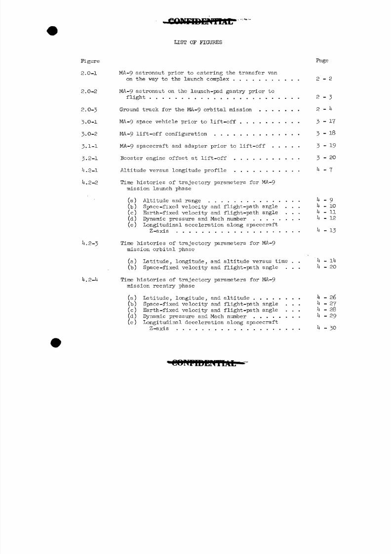
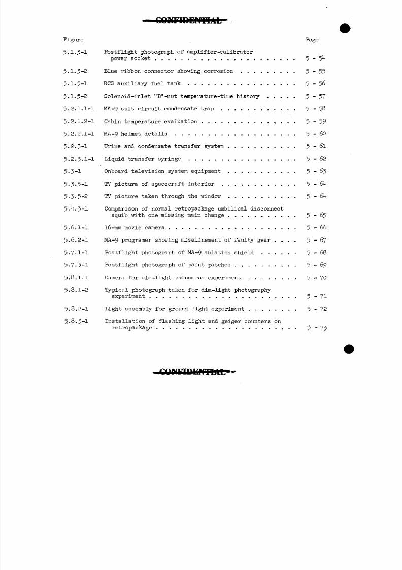
Figure Page
5.1-3-1 Postflight photograph of amplifier -calibrator
power socke't ... ................... 5-
5.1-3-2 Blue ribbon connector showing corrosion ......... 5-55
5.1.5-1 RCS auxiliary fuel tank ................. 5-56
5.1.5-2 Solenoid-inlet "B"-nut temperature -time history ..... 5-57
5.2.1.1-1 MA. -9 suit circuit condensate trap ............ 5-58
5.2.1.2-1 Cabin temperature evaluation ........... ^ . . . 5-59
5.2.2.1-1 MA-9helmet details ................... 5 - 60
5.2.3-1 Urine and condensate transfer system ........... 5 - 6l
5.2.3.1-1 Liquid transfer syringe ................ . 5-62
5.3-1 Onboard television system equipment ........... 5 - 63
5.3-5-1 TV picture of spacecraft interior ............ 5 - 6U
5-3.5-2 TV picture taken through the window ........... 5-64
5 - 4.3-1 Comparison of normal retropackage umbilical disconnect
squib with one missing main change ........... 5-65
5.6.1-1 l6-mm movie camera .......... -. ......... 5-66
5.6.2-1 MA-9 programer showing misalinement of faulty gear .... 5-67
5.7.1-1 Postflight photograph of MA-9ablation shield ...... 5-68
5.7-3-1 Postflight photograph of paint patches .......... 5-69
5.8.1-1 Camera for dim -light phenomena experiment . . ...... 5-70
5.8.1-2 Typical photograph taken for dim-light photography
experiment ....................... 5-71
5.8.2-1 Light assembly for ground light experiment ........ 5-72
5-8.3-1 Installation of flashing light and geiger counters on
retropackage ...................... 5-73
8/7/2019 Post Launch Memorandum Report for Mercury-Atlas No. 9(MA-9). Part 1 Mission Analysis
http://slidepdf.com/reader/full/post-launch-memorandum-report-for-mercury-atlas-no-9ma-9-part-1-mission 9/344
Figure Page
5.8A-1 Hasselblad 500-C'camera modified forMA-9mission ... 5 - 7^
5.8A-2 Infrared photograph taken for U.S.Weather Bureau
experiment over Florida peninsula 5-75
5.8.5-1 Quadrantal photograph taken for horizon-definitionexperiment » " V : • • 5-76
5.8.6-1 Equipment for flashing-light' experiment ..."...'.. 5-77
5.8.6-2 Topical history trace of flashing light output ; . . . . 5-78
5-8.6-3 Typical horizontal intensity distribution of theflashing light 5-79
5.8.6- Calculated sighting parameters for flashing-lightexperiment . ' ' . . ' . . . . 5 - 80
f t
5.8.8-1 Photograph'of Himalaya Mountains taken withHasselblad camera . ' •'. . . .5 -.8
6.8-1 Space-fixed velocity and flight-path angle in theregion of cut-off using launch-vehicle guidancedata
(a) Space-fixed velocity . . . . . 6-7
fb) Space-fixed flight-path angle . . 6-8
6.8-2 Space-fixed velocity and flight-path angle in t;heregion of cut-off using IP 709 data
(a) Space-fixed velocity . . ' , . . 6-9.
(b) Space-fixed flight-path angle . . . . . . . . . . '"6-10
6.-'8-5 Space-fixed flight-path angle versus space-fixedvelocity in the region of cut-off 6-11
7.1.2.2-1 Oral temperature probe 7-91
7.1.2.2-2 Installation of oral temperature probe in helmet . . . . 7-92
7.1.2.2-3 MA-9May l , 1963, 07: 2:00 e.s.t. Sample record
illustrating nodal beats occurring during canceledlaunch count down. Recorder speed 25 mm/sec ..'.'.. 7-93
C OPlPf f iENTlAL
8/7/2019 Post Launch Memorandum Report for Mercury-Atlas No. 9(MA-9). Part 1 Mission Analysis
http://slidepdf.com/reader/full/post-launch-memorandum-report-for-mercury-atlas-no-9ma-9-part-1-mission 10/344
C O N F I D E N T I A L
Figure Page
7.1.2.2-4 MA-9 16:11:30 - Sample of biosensor record at a rangestation illustrating one of the frequent occurrencesof sinus arrhythmia with wandering of the cardiac
pace maker. In this sample, the negative P wavesuggests inverse depolarization from the atrioventri-cular node. Similar changes were observed before
7.1.3.1-1
7.1.3.2-1
7.1.5.1-1
7.1.5.1-2
7.1.5.2-1
7.1.5.2-2
7.2.2.2*1
7.2.2.2-2
7.2.2.2-3
7.2.3.1-1
7.2.3.5-1
7.2.4.2-1
7.2.4.2-2
9.1-1
9.2-1
9.2-2
MA-9 12:29:52 - Sample of typical biosensor datareceived at a range station. Blood pressure,
Tilt studies - heart rate responses .....
Tilt studies - blood pressure responses for MA-9
Exercising device used for calibrated work
Calibrated work -MA-9. .
Special equipment storage kit
Planned landing areas
fa) Atlantic Ocean
(b) Pacific Ocean .
MA-9 spacecraft in auxiliary flotation collar with line
i
7
7
7
7
7
7
7
7
7
7
7
- 7
7
9
9
9
9
s .
- 95
-96
- 97
-98
- 99
- 100
- 101
- 101
- 102
- 103
- 104
- 105
- 106
- 6
- 7
- 8
- 9 "
8/7/2019 Post Launch Memorandum Report for Mercury-Atlas No. 9(MA-9). Part 1 Mission Analysis
http://slidepdf.com/reader/full/post-launch-memorandum-report-for-mercury-atlas-no-9ma-9-part-1-mission 11/344
iNTIAL
Figure • Bage
9.2-3 Side hatch being actuated on MA-9 spacecraft 9-10
9.2-4 Astronaut Cooper egressing from.MA-9 spacecraft .... 9 - H
9.3-1 Details of landing area 22-1 9-12
10.3-1 Wind direction and velocity at launch site 10-17
10.5-2-1 AMR engineering sequential tracking camera coverage . . 10-18
10.6-1 Postflight photograph of MA-9 spacecraft 10-19
8/7/2019 Post Launch Memorandum Report for Mercury-Atlas No. 9(MA-9). Part 1 Mission Analysis
http://slidepdf.com/reader/full/post-launch-memorandum-report-for-mercury-atlas-no-9ma-9-part-1-mission 12/344
N O T I C E
NO. 1: LIFT-OFF TIMS (2-INCH MOTION) FOR THE MA-9 FLIGHT WAS
8:04:13.106A.M.E.S.T. RANGE ZERO TIME WAS ESTABLISHED
AS 8:04:13 A.M.E.S.T. ALL TIMES REFERRED TO IN THIS
REPORT ARE IN ELAPSED TIME IN HR:MIN:SEC FROM RANGE ZERO
UNLESS OTHERWISE NOTED.
NO. 2: THE MA-9 POSTLAUNCH MEMORANDUM REPORT IS IN THREE PARTS,
UNDER SEPARATE COVERS, AS FOLLOWS:
PART I - MISSION ANALYSIS - CONTAINS AN OVERALL ANALYSIS
OF THE MISSION AND PRESENTS A MINIMUM OF DATA.
PART II - DATA - CONTAINS COMPLETE TIME HISTORIES OF
SPACECRAFT DATA, WITHOUT ANALYSIS.
PART III - MISSION TRANSCRIPTS - CONTAINS ESSENTIALLY
UNEDITED TRANSCRIPTS OF THE FLIGHT COMMUNICATIONS,,THE
PILOT'S POSTFLIGHT SELF-DEBRIEFING, AND THE FORMAL TECHNICAL
DEBRIEFING CONDUCTED ONBOARD THE RECOVERY AIRCRAFT CARRIER.
IDEMTVb.
8/7/2019 Post Launch Memorandum Report for Mercury-Atlas No. 9(MA-9). Part 1 Mission Analysis
http://slidepdf.com/reader/full/post-launch-memorandum-report-for-mercury-atlas-no-9ma-9-part-1-mission 13/344
AL Page 1-1
1.0 MISSION SUMMARY
The MA-9mission was successful in nearly every respect. The plannedlaunch time of 8:00 a.m. e.s.t. oh May l4, 19&3; was postponed for 1 day
because of intermittent digital data in both the azimuth and rangechannels of the C-band radar at Bermuda. Prior to postponement, the
countdown had proceeded as planned until T-60 minutes, when an unscheduledhold of 2 hours and 9 minutes became necessary because of a fuel-pumpfailure in the diesel engine on the gantry transfer table. After thishold, the countdown was continued until T-13 minutes when the flightwas postponed because of the radar problem. The launch operation on
May 15, 1963, was "the most efficient conducted to date. Four minutesof unplanned hold time were required to evaluate an external RF inter-ference problem at the guidance central rate station. Weather conditionsat the launch site and in the primary landing area were satisfactory.
Lift-off occurred at approximately 8:04 a.m. e.s.t. on May 15, 19 3
2 hours and 31 minutes after the astronaut entered the spacecraft.
Launch-vehicle performance was excellent, and the trajectoryparameters displayed at the Mercury Control Center indicated a "go"condition at insertion. A near-perfect orbit was attained, with deviations
from planned postposigrade values of space-fixed flight-path angle and
velocity of 0.0037° and -1.4 ft/sec, respectively. Both the perigeeand apogee of the initial orbit differed from the planned values of87 and 1^4 nautical miles by 0.2 nautical mile. The decay in perigee
and apogee after nearly 22 orbital passes was 1.6 and 7-1 nauticalmiles, respectively.
Spacecraft separation from the launch vehicle was satisfactory andthe planned manual turnaround was well executed by the pilot. Theperformance of the spacecraft systems was excellent for the first18 orbital passes with the exception that the automatic section of the
programer failed at 12:18:19- In addition, several minor problemswere encountered with the R and Z calibrations, the drinking-watervalve, and the condensate transfer system. Upon contacting Hawaii
on the 19th orbital pass, the pilot reported that the 0.05g warninglight had come on. Systems checks by the astronaut revealed that the
amplifier-calibrator was in the 0.05g configuration and that the ASCScould be used only during reentry. However, planned use of the ASCS
for reentry was abandoned at about 33:07:00 when neither the main nor
the standby 250 v-amp inverters would supply electrical power to theASCS bus. The pilot manually initiated the required retrofire andreentry events. He controlled the spacecraft attitudes during retro-fire by utilizing the manual proportional system. Because of the ASCSfailure, the pilot was also required to conduct the reentry maneuvermanually, and he elected to use both the manual proportional and fly-
by-wire modes during this phase.
8/7/2019 Post Launch Memorandum Report for Mercury-Atlas No. 9(MA-9). Part 1 Mission Analysis
http://slidepdf.com/reader/full/post-launch-memorandum-report-for-mercury-atlas-no-9ma-9-part-1-mission 14/344
P a g e i - 2
The pilot's performance throughout the mission was excellent, and
he adhered closely to the flight plan until the ASCS problems occurred.
The pilot had no difficulty in sleeping during the mission, although
he woke up several times during the planned rest period and found it
necessary to reestablish a comfortable suit temperature. He did not
eat and drink as much as was desirable, and he has since commented onthe difficulty of performing these functions with the devices that were
available to him. Six of the eight planned scientific experiments were
successfully conducted during the mission. The balloon drag and
visibility experiment was not accomplished because of failure of the
balloon to deploy, and the window attenuation experiment was not
accomplished because the pilot could not get the standard light source
out of the special equipment storage kit.
The pilot's control of the spacecraft during retrofire and reentry
was excellent and resulted in a landing only k.k nautical miles from
the prime recovery ship, the aircraft carrier U.S.S. Kearsarge. Visual
contact was made from the carrier and the. recovery helicopters reachedthe spacecraft and circled it during its descent. Swimmers were
deployed from the helicopters and they immediately attached a flotation
collar to the spacecraft. The pilot remained in the spacecraft until
it was hoisted aboard the carrier, the hatch had been blown, and the
doctors had given him a preliminary examination. The pilot egressed
from the spacecraft in good condition kO minutes after landing. A
postflight physical examination conducted onboard the recovery ship
revealed no evidence of significant degradation of pilot function directly
attributable to the space flight. The pilot demonstrated an orthostatic
rise in heart rate and fall in blood pressure which was more pronounced
than that detected after the MA-8 flight. Although this condition is
not an inflight hazard, the implications of this hemodynamic response
on return to Ig conditions will have to be given very serious consider-
ation for longer missions.
Support activities from all ground elements, including flight
control, Mercury Network, and recovery, were excellent and contributed
greatly to the successful accomplishment of the mission.
Postflight examination of the spacecraft and evaluation of the data
collected during the mission have revealed some anomalies, and detailed
systems tests have determined the most likely causes of the major
problems. Considerable information regarding man's capabilities to
perform his assigned tasks during extended periods of time in the space
environment has been obtained. Evaluation of the overall mission indicates
that a high degree of success was obtained and confirms the accomplishment
of all mission objectives.
8/7/2019 Post Launch Memorandum Report for Mercury-Atlas No. 9(MA-9). Part 1 Mission Analysis
http://slidepdf.com/reader/full/post-launch-memorandum-report-for-mercury-atlas-no-9ma-9-part-1-mission 15/344
2.0 INTRODUCTION
Page 2-1
The first manned 1-day mission (MOEM) as a part of the United
States' program of space exploration was successfully accomplished
on May 15 and May 1.6, 1963- This mission was the fourth mannedorbital flight in Project Mercury. It was also the ninth of a series
of flights utilizing production Mercury spacecraft and Atlas launch
vehicles and, therefore, was designated Mercury-Atlas Mission 9 (MA-9).
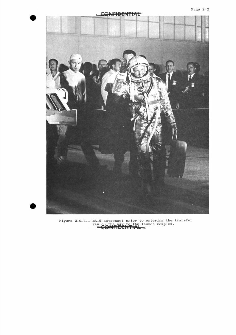
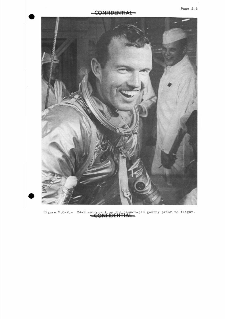
Astronaut L. Gordon Cooper, Jr., shown in figures 2.0-1 and 2.0-2,
was the spacecraft pilot for this flight.
The MA-9 space vehicle was launched from the Missile Test Annex at
Cape Canaveral, Florida, at 08:OU a.m. e.s.t. on May 15, 1963 The
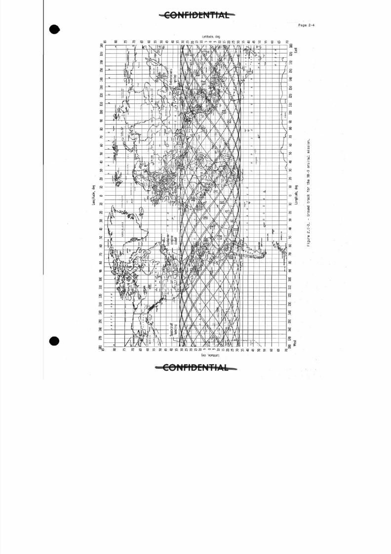
flight ended as planned, after completing nearly 22 orbital passes around
the earth, with a successful landing approximately 70 nautical miles
southeast of Midway Island in the Pacific Ocean at 06:2 p.m. e.s.t. on
May l6, 1963. Ground tracks for the 22 orbital passes of the MA-9 space-craft are shown in figure 2.0-3-
The MA-9 mission was a continuation of a pioneering program to acquire
operational experience and information for extended manned orbital space
flight. The objectives of the flight were to evaluate the effects on the
astronaut of approximately 1 day in orbital flight; to verify that man
can function for an extended period in space as a primary operating system
of the spacecraft; to evaluate in a manned 1-day mission the combined
performance of the astronaut and a Mercury spacecraft specifically modi-
fied for the mission; to obtain the astronaut's evaluation of the opera-
tional suitability of the spacecraft and supporting elements for extended
manned orbital flight; and to assess the effectiveness of the Mercury
Worldwide Network and mission support forces during an extended manned
orbital flight. Each of these objectives was satisfactorily fulfilled.
A preliminary analysis of the significant flight data has been made,
and the results are presented in this report. Brief descriptions of the
mission, the spacecraft, and the launch vehicle are followed by the per-
formance analyses and supporting data. All major events of the MA-9
mission, beginning with delivery of the spacecraft to the launch site and
continuing through recovery and postflight examination, are documented.
The graphical information presented herein has been included to
support and clarify the text; however, the reader is referred to Part II,
Data, for a complete presentation, without analysis, of all MA-9 time-
history flight data. Part III, Mission Transcripts, presents essentially
unedited transcripts of the flight communications, the pilot's postflight
self-debriefing, and the formal technical debriefing conducted onboard
the recovery aircraft carrier.
W T O B M T I A I i
8/7/2019 Post Launch Memorandum Report for Mercury-Atlas No. 9(MA-9). Part 1 Mission Analysis
http://slidepdf.com/reader/full/post-launch-memorandum-report-for-mercury-atlas-no-9ma-9-part-1-mission 16/344
Figure 2.0-1.- MA-9 astronaut prior to entering the transferva n i e . a . Q . b ] e launch complex.9Ji«JAep.j ak%.,kQp.3b]ael
8/7/2019 Post Launch Memorandum Report for Mercury-Atlas No. 9(MA-9). Part 1 Mission Analysis
http://slidepdf.com/reader/full/post-launch-memorandum-report-for-mercury-atlas-no-9ma-9-part-1-mission 17/344
Page
Figure 2.0-2.- MA-9 astronaut on the launch-pad gantry prior to fligh
8/7/2019 Post Launch Memorandum Report for Mercury-Atlas No. 9(MA-9). Part 1 Mission Analysis
http://slidepdf.com/reader/full/post-launch-memorandum-report-for-mercury-atlas-no-9ma-9-part-1-mission 18/344
Page 2-4
Latitude, deg
C O M r i D C M T I A f e .
8/7/2019 Post Launch Memorandum Report for Mercury-Atlas No. 9(MA-9). Part 1 Mission Analysis
http://slidepdf.com/reader/full/post-launch-memorandum-report-for-mercury-atlas-no-9ma-9-part-1-mission 19/344
8/7/2019 Post Launch Memorandum Report for Mercury-Atlas No. 9(MA-9). Part 1 Mission Analysis
http://slidepdf.com/reader/full/post-launch-memorandum-report-for-mercury-atlas-no-9ma-9-part-1-mission 20/344
3 - 2
6. A "rate indicate" switch with an automatic and manual
position was added. In the mnaual position, telemetry and
pilot-indicated rates were given continuously; and in the auto-
matic position, the rate indications were cut off from the time
of spacecraft separation plus 5 minutes to 10 minutes before
retrosequence time.
#7- An "out-of-orbit mode" warning light and tone switch
were added. This circuit was available from 5 minutes after
spacecraft separation until the beginning of retrosequence.
3.1.1.2 Reaction control system:
1. The 1-pound and 6-pound thrusters of the reaction
control system (RCS)were replaced with units of an improved
design.
^2. The nitrogen tank in the automatic RCS was pressurizedto 2,800 psi instead of 2,250 psi, as in previous missions.
3. A special corrosion-deterrent paint was applied to
the outside of all hydrogen peroxide (H 0 ) tanks.
U. A dual indicator was added to the instrument panel
to display to the astronaut the regulated nitrogen pressures
in the automatic and manual reaction control system.
5 - The time-delay relay used in the jettison of HO was
changed to extend the jettison time from 60 seconds to
150 seconds.
61. The wall thickness of the expulsion tubes of the
automatic and manual HO tanks was increased from 0.062 inch
to 0.125 inch.
•"-7. A 15-pound capacity HO tank was added in parallel
with the automatic HO tank.
-«8. A manually operated interconnect valve was added to
provide the capability to transfer fuel between the automatic
and manual HO fuel systems.
9. A drain and purge valve was added to the automatic
and manual HO systems.
10. The nitrogen and hydrogen peroxide relief valves were
replaced with units of a more reliable type.
8/7/2019 Post Launch Memorandum Report for Mercury-Atlas No. 9(MA-9). Part 1 Mission Analysis
http://slidepdf.com/reader/full/post-launch-memorandum-report-for-mercury-atlas-no-9ma-9-part-1-mission 21/344
Page 3-3
3.1.2 Life support system. -
3-1.2.1 Environmental control system:
1. The electrical inverters were cooled by using heat
sinks and ducted cabin air circulation, rather than the pre-viously used coolant circuit and heat exchanger.
*2. The CO adsorption capacity was increased by adding
0.8 pound of lithium hydroxide to the CO canister. The amount
of charcoal in the canister was reduced to 0.2 pound.
3. A provision was added for manually sealing the cabin
pressure-relief valve from water leakage at landing.
k. The warning light for indicat ing exce ss water or low
temperature in the suit or cabin heat exchangers was made de-pendent upon the associated dome temperature.
- : ; - 5 - The cabin oxygen-partial-pressure indicator was re-
placed with a dual indicator displaying cabin 0 partial
pressure and suit-circuit CO partial pressure. Also, a warn-
ing light and a tone switch were ad ded to the panel to indicate
excessive CO .
6. A redundant coolant-control valve was added in parallel
with the existing valve for the suit cooling circuit. Also,
these valves and the cabin coolant-control valve were of animproved design.
#7- An oxygen bottle containing h pounds of oxygen was
added in parallel to the primary oxygen bott le.
•;:'8. A 9-pound coolant water tank was added in parallel
with the existing 39-P°und coolant water tank.
9. The suit and cabin freon orifices and check valves
were replaced with units of an improved design.
10. The primary and secondary oxygen high-pressure regu-lators were replaced with modifie d units of an improved design.
*L1. The secondary oxygen-supply system had a warning
light and tone switch for an indicati on to the pilot when
pressure in the oxygen bottle dropped below 6,500 psi.
C O N F I D E N T I A L
8/7/2019 Post Launch Memorandum Report for Mercury-Atlas No. 9(MA-9). Part 1 Mission Analysis
http://slidepdf.com/reader/full/post-launch-memorandum-report-for-mercury-atlas-no-9ma-9-part-1-mission 22/344
Page 3 - k
12. The emergency oxygen rate valve was replaced with one
of an improved design.
IJ. The pressurization system for the coolant-water
supply was provided with gas pressure from the suit circuit
only.
Ik. The pressure-sensing circuit that was used to cut
off the ca~bin fan and energize a warning light indicating low
cabin pressure was removed.
-"-15. A timer circuit was installed to actuate the water-
separator sponge for a JO-second period every 10 minutes.
16. A "sponge-squeeze" switch and water-separator travel
indicator lights were added to the main instrument panel to
allow automatic or manual initiation of the water separator
and to provide a visual aid for monitoring the separator piston
position.
17. The absolute-pressure relief valve was removed from
the coolant-water pressurization system.
18. Insulation was added to the CO absorber, and a
deflector was added to the cabin fan outlet to prevent cold
air from the cabin heat exchanger from impinging on the CO
absorber.
19. A screen was added over the relief port of the
negative pressure relief valve to prevent objects from fallinginto the valve opening.
20. The suit inlet for emergency oxygen flow was re-
positioned upstream of the suit-circuit CO partial pressure
sensor. This change permitted purging of the sensor with
100-percent oxygen to verify its operation.
#21. A condensate trap was installed in the suit circuit
to aid in removing water.
22. The suit-circuit ducting, from the water separatorto the junction of the suit-inlet flexible hose, was insulated
to reduce heat loss.
3.1.2.2 Food, water, and waste management:
*1. Condensate and urine transfer systems were installed.
8/7/2019 Post Launch Memorandum Report for Mercury-Atlas No. 9(MA-9). Part 1 Mission Analysis
http://slidepdf.com/reader/full/post-launch-memorandum-report-for-mercury-atlas-no-9ma-9-part-1-mission 23/344
Page 3-5
2. The nylon drinking-tut)e assembly from the 39-pound
coolant water tank was removed.
#3- An expulsion-type drinking-water container was added.
The tank contained a transfer fitting to provide the capabil-
ity of transferring condensate to the tank after the drinkingwater was consumed.
3.1.2.3 Pull-pressure suit:
1. The sealing technique for the faceplate on the helmet
was changed from pneumatic to mechanical. In addition, small
velcro tape patches for attaching the oral temperature pro"be
to the right earcup, radiation film badges attached to the
helmet shell, and an improved helmet tiedown system were in-
stalled.
2. The torso section of the pressure suit was modifiedin the shoulder and wrist areas. In addition, the boots were
made a permanent part of the torso assembly, and they were
provided with improved ventilation.
3 - A poppet-type valve was added to the suit-inlet venti-
lation fitting to prevent water from entering the suit should
the astronaut leave the spacecraft and enter the water after
landing.
h. An additional locking feature was added at the
glove-to-torso connection to prevent accidental disengagement.
•"•5. A urine transfer fitting was added to the suit.
6. The lifevest pack was moved to the front of the
lower left leg since this was a m©re convenient location.
7- Items carried in pockets on the suit included a
handkerchief, pocket folding knife, biomedical injectors,
heavy-duty scissors, and a mechanical pencil.
3.1.2. Personal equipment:
1. The navigation yaw reticle was deleted.
2. An opaque window cover was added to the spacecraft
window, and the red window filter and the map case were removed.
8/7/2019 Post Launch Memorandum Report for Mercury-Atlas No. 9(MA-9). Part 1 Mission Analysis
http://slidepdf.com/reader/full/post-launch-memorandum-report-for-mercury-atlas-no-9ma-9-part-1-mission 24/344
3- A work-table and storage space assembly was added in
front of the main instrument panel pedestal.
U. The flashlight, the food container, the knife mounted
on the spacecraft structure, and the waste container were
removed.
*5- An exercising device of the type used during the
MA-6 flight was added.
6. The rear-view mirror was removed.
3.1.3 Communications system.-
1. The hardline cable which allowed operation of the
voice communications system outside of the spacecraft was
deleted.
2. Nitrogen gas pressure from the manual RCS was used
to deploy the HP recovery antenna.
3- The fingers were removed from the bicone antenna to
improve communications while in the attitude-free drifting-
flight mode.
*k. The back-up UHF voice transmitter-receiver was
removed.
5 - The capability for ground command of the telemetry-
system and radar-beacon operation was incorporated.
6. The HP voice transmitter was disabled from the time
of antenna-fairing separation to the time of HF recovery
antenna deployment to prevent damage to the voice system.
7. A switch was added to allow the pilot to disable the
UHF power amplifier for increased reliability of the UHF trans-
mitter-receiver system.
8. A slow-scan television system was added for real-time
observation of the pilot and spacecraft environment. The TV
transmitter was also available as a backup to the T^VI trans-mitter.
9- The phase-shifter switch was removed, and the phase
shifter was controlled by a relay such that it was on whenever
the C-band beacon was on. Phase-shifter power was changed from
the ASCS bus to the fans bus.
8/7/2019 Post Launch Memorandum Report for Mercury-Atlas No. 9(MA-9). Part 1 Mission Analysis
http://slidepdf.com/reader/full/post-launch-memorandum-report-for-mercury-atlas-no-9ma-9-part-1-mission 25/344
Page 3-7
10. Deployment of the HF orMtal antenna was effected by
only one bellows motor, 10 seconds after spacecraft separation.
11. A control unit was added to allow the pilot to set
a high volume on his receiver with a minimum of side tone
while transmitting.
12. The miniaturized helmet microphone was modified to
include noise rejection characteristics. The helmet was also
modified to include two miniaturized earphones in each ear-
piece.
J.lA Mechanical and -pyrotechnic systems. -
*1. The periscope was removed, and a spring-loaded device
was used to close umbilical door.
2. The SOFAR bomb on the main parachute riser was setto detonate at a depth of 3,000 feet.
3. The main and reserve parachute deployment bags were
modified for increased reliability.
U. The landing-bag release system was modified to im-
prove its reliability.
5. A redesigned survival kit pan was installed.
6. One of the two squibs in the retropackage explosive
jettison bolt was disarmed because it contained a ground loopcircuit.
7 - The explosive-actuated hatch actuator cap was vented.
3.1.5 Electrical and sequential systems.-
1. A redundant 3-volt power supply was added for instru-
mentation reference. It could be actuated by the astronaut for
an instrumentation reference of flight-critical items in case
of failure of the primary 3-volt power supply.
2. The eight day correlation clock was removed.
3- The satellite clock was powered by the 2 v d-c main
bus rather than the isolated bus.
^. An "off" position was added to the instrument-panel
warning-light circuit to turn off all lights except those for
the satellite clock for improved pilot dark adaptation.
iV711r UL/IMl 1lALi
8/7/2019 Post Launch Memorandum Report for Mercury-Atlas No. 9(MA-9). Part 1 Mission Analysis
http://slidepdf.com/reader/full/post-launch-memorandum-report-for-mercury-atlas-no-9ma-9-part-1-mission 26/344
p a g e 3 - 8 . OOHriDCNTIAL
5. The main inverters were replaced with those of an im-
proved design having superior thermal characteristics and a
greater efficiency.
#6. In order to provide increased power for the longer
MA-9 mission, five 3 000 watt-hour and one 1,500 watt-hourbatteries were flown in spacecraft 20 instead of the three
3,000 watt-hour and the three 1,500 watt-hour batteries flown
in spacecraft l6 (NLA-8).
7- The fire retro, green telelite was made dependent on
the ignition of all three retrorockets rather than being
dependent on the ignition of the third retrorocket, as was the
case for spacecraft 16.
8. A switch was added to provide the astronaut with the
capability of turning off the flashing recovery light to con-
serve power during daylight hours.
9. An auxiliary portable light was installed for the
astronaut's use during flight.
10. A switch was added to allow turning the prelanding
buses back on once the landing relay timed out to permit post-
landing blood-pressure and EGG recordings.
11. A tower-jettison arm relay was added in the tower-
jettison circuit to prevent inadvertent firing of the tower-
jettison rocket.
12. A green telelite was provided to give the astronaut
an indication of umbilical door closure, and a red telelite
was provided to indicate when the door was open. The door posi-
tion was also monitored by telemetry.
13. A tower-separation abort-interlock relay was added on
the 2h- v d-c isolated squib bus. If an abort signal were to be
received by the spacecraft and power from the main squib bus
were lost, initiation of retropackage jettison would occur when
spacecraft separation was sensed. Tower-jettison rocket igni-
tion would occur when tower-clamp-ring separation was sensed.
1 . Both the main and isolated bus circuits for the retro-
rocket ignition squibs were controlled by the retrofire arm
circuit. This change was made to improve the switching arrange-
ment for the astronaut. Only the main squib-bus circuits were
so controlled on spacecraft 16.
8/7/2019 Post Launch Memorandum Report for Mercury-Atlas No. 9(MA-9). Part 1 Mission Analysis
http://slidepdf.com/reader/full/post-launch-memorandum-report-for-mercury-atlas-no-9ma-9-part-1-mission 27/344
Page 3 - 9 * " -;
15. The automatic retrofire arm feature was made functional
for all retrosequence modes except manual retrofire, with or
without attitude permission. As a result,, whenever the pilot
elected to ignite the retrorockets using the retrofire switch,
the retrorocket arm switch had to "be in manual position.
16. The Mayday circuit was powered from the main bus; it
was powered from the main squib bus on spacecraft 16.
IT- A rescue aids switch was rewired to provide the
astronaut with the capability of manually extending the HF
recovery antenna after landing.
18. Three diodes were put in series with the flashing
light to prevent damage to the light, because the light was
powered by the 6-volt isolated bus, rather than its own
self-contained battery.
19. A resistor was added to the command input circuit of
the programer to reduce the programer's susceptibility to
transient voltage spikes.
20. A standby inverter automatic tone generator was added
to indicate automatic switching of the inverter to either a-c
bus.
21. The emergency reserve parachute deployment and the
emergency landing-bag-deployment circuits were powered through
switch fuses.
22. The satellite clock, pilot, and ground command retro-
sequence signals were powered through a common fuse switch.
23. An emergency spacecraft separation bolt relay was
added in the spacecraft-separation pull-ring circuitry to allow
the pilot to fire the escape rocket with isolated bus power
only.
2 -. Two spacecraft-separation-sensor relays were added to
the isolated squib bus. One relay improved the reliability of
the maximum-altitude sensor and the other was used in the
tower-separation abort-interlock relay circuitry.
25- Automatic 21,000-foot drogue-parachute deployment was
made more reliable by paralleling the main and isolated squib
arming circuits.
8/7/2019 Post Launch Memorandum Report for Mercury-Atlas No. 9(MA-9). Part 1 Mission Analysis
http://slidepdf.com/reader/full/post-launch-memorandum-report-for-mercury-atlas-no-9ma-9-part-1-mission 28/344
Page 3-10
3.1.6 Instrumentation system.-
1. A switch was added to provide the astronaut with the
capability to remove electrical power from the R- and
Z-calibration relays. This switch would be used to stop
calibrations should the programer fail 1;operform this function
as planned.
2. The HF telemetry system was deleted from the spacecraft.
3. The low-level commutator and temperature-survey pick-
ups were removed from the spacecraft.
^ 4 - . Several timing functions were added to the programer.
In spacecraft 1.6, its only function was programing the water-
squeezer operation.
5. The frequency of the voltage-controlled oscillator
for the automatic-solenoid malfunction detector was changed to
3-9 kc to provide better tape-recording reproduction of this
function.
6. The "A" package of the instrumentation system was
modified to protect the d-c amplifiers from over voltage and
to provide for a better reading of the 115 v a-c fans bus.
7- The oxygen-quantity indicator was expressed in per-
cent. Maximum indication was 250 percent on primary and
125 percent on secondary.
8. The R- and Z-calibration signals were no longer
initiated only on ground command. They were initiated when
the telemetry transmitter was energized through the command
link and when the tape recorder was programed.
9. The tape-recorder operation was no longer completely
continuous. It was modified to run at a speed of rr inch
per second, giving a longer recording capability, and its
operation was either off, programed, or continuous, as selected
by the pilot.
10. A three-position switch with off, continuous, and
ground-command positions was added for astronaut control of
telemetry transmitter operation.
11. The astronaut-observer camera was replaced with a
self-contained, hand-held moving-picture camera. This camera
was a l6-mm type that could be mounted on the instrument panel
for observation of the pilot or on a special bracket to photo-
graph through the window.
8/7/2019 Post Launch Memorandum Report for Mercury-Atlas No. 9(MA-9). Part 1 Mission Analysis
http://slidepdf.com/reader/full/post-launch-memorandum-report-for-mercury-atlas-no-9ma-9-part-1-mission 29/344
12. The retrorocket temperature sensor was moved from
the right to the bottom retrorocket.
13. The low-fuel-pressure -warning switch was changed
from a 1,580-psi switch to a 2,200-psi switch, and the auto-
matic ECS high-pressure transducer range was 0 to 3,500 psi.
1 . The cabin and heat exchanger dome temperature light
and tone alarm replaced the excess cabin and suit excess
water light and tone alarm.
15. Suit outlet temperature was sensed by the body tem-
perature sensor when the sensor was not measuring body
temperature. Temperature range of the sensor was 75° F to
108° F.
16. Temperature sensors were installed in all three fuel
tanks, and the temperatures were displayed on an instrument-panel indicator.
17. Standby inverter and cabin heat-exchanger outlet
temperatures were telemetered to the ground.
18. The blood-pressure-measuring system controller was
changed to provide easier gain adjustment.
3.1.7 Heat-protection system.-
1. Six bolts were added to the ablation heat shield to
retain the shingle portion of the shield in case of delamina-tion at landing.
2. In addition to the previously flown rectangular paint
patch, two new types of paint were added for evaluation.
3.1.8 Experiments.-
1. A tethered balloon similar to that flown during the
MA-7 mission was packaged in the antenna canister.
2. A self-contained flashing beacon was installed on the
retropackage.
3- Two geiger counters, a dosimeter, four film badges,
and a Schaeffer radiation package were installed on or in the
spacecraft to determine radiation exposure during the flight.
8/7/2019 Post Launch Memorandum Report for Mercury-Atlas No. 9(MA-9). Part 1 Mission Analysis
http://slidepdf.com/reader/full/post-launch-memorandum-report-for-mercury-atlas-no-9ma-9-part-1-mission 30/344
Page 3-12
U. A special 35-™m camera was added for use in photo-graphing the zodiacal light and the airglow layer.
5. A special 70-rnm Hasselblad camera was added for usein taking general color photographs, infrared weather photo-
graphs, and horizon definition photographs.
8/7/2019 Post Launch Memorandum Report for Mercury-Atlas No. 9(MA-9). Part 1 Mission Analysis
http://slidepdf.com/reader/full/post-launch-memorandum-report-for-mercury-atlas-no-9ma-9-part-1-mission 31/344
Page 3-13
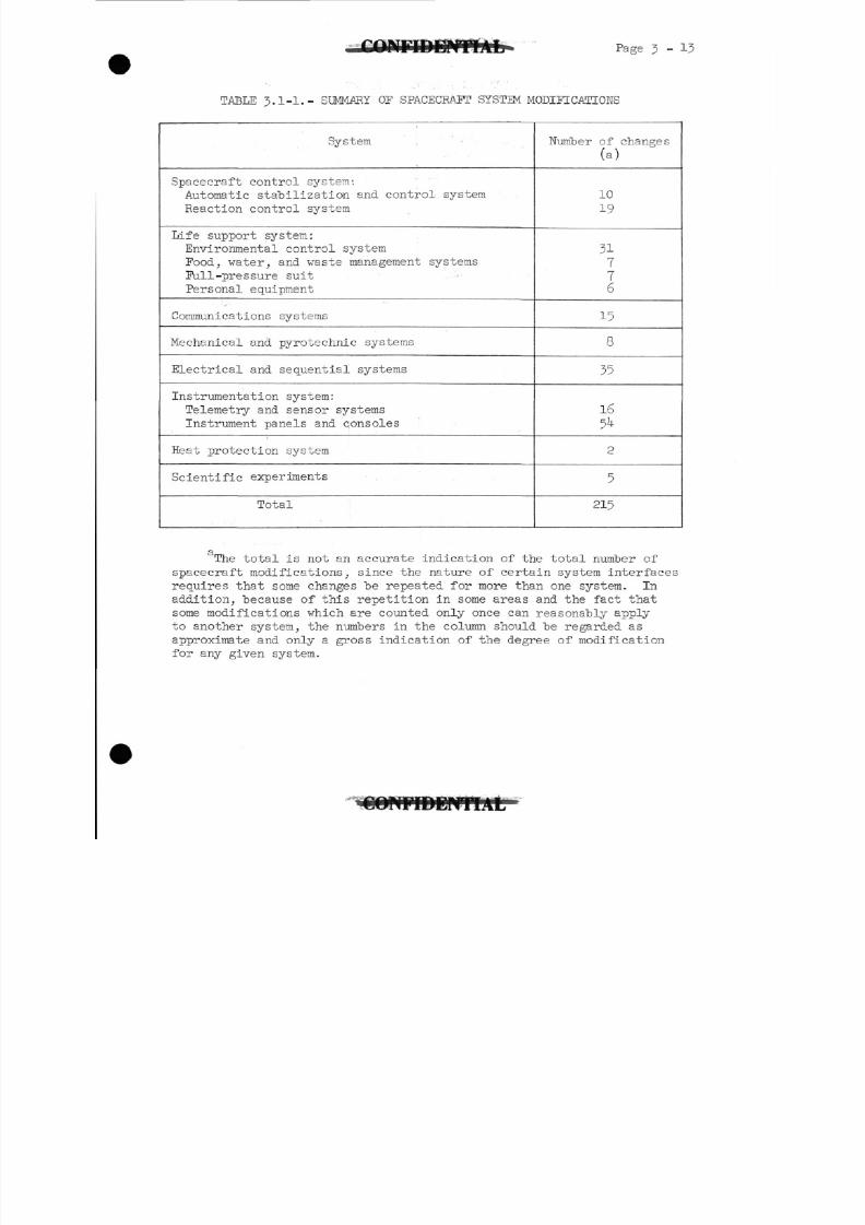
TABLE 3.1-1.- SUMMARY OF SPACECRAFT SYSTEM MODIFICATIONS
System
Spacecraft control system:
Automatic stabilization and control system
Reaction control system
Life support system:
Environmental control system
Food, water, and waste management systems
Full-pressure suit
Personal equipment
Communications systems
Mechanical and pyrotechnic systems
Electrical and sequential systems
Instrumentation system:
Telemetry and sensor systems
Instrument panels and consoles
Heat protection system
Scientific experiments
Total
Number of changes
(a)
10
19
31776
15
8
35
16
5^
2
5
215
The total is not an accurate indication of the total number of
spacecraft modifications, since the nature of certain system interfaces
requires that some changes be repeated for more than one system. In
addition, because of this repetition in some areas and the fact that
some modifications which are counted only once can reasonably apply
to another system, the numbers in the column should be regarded as
approximate and only a gross indication of the degree of modification
for any given system.
8/7/2019 Post Launch Memorandum Report for Mercury-Atlas No. 9(MA-9). Part 1 Mission Analysis
http://slidepdf.com/reader/full/post-launch-memorandum-report-for-mercury-atlas-no-9ma-9-part-1-mission 32/344
Page 3 -
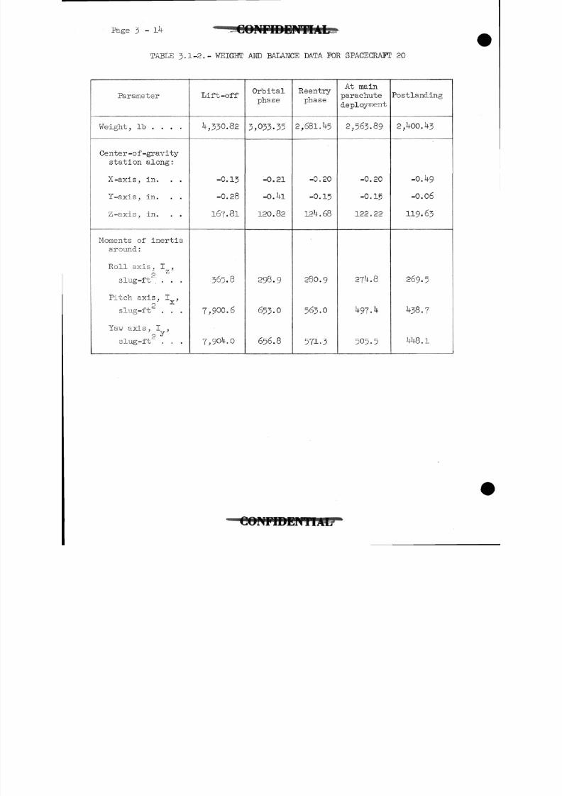
TABLE 3.1-2.- WEIGHT AND BALANCE DATA FOR SPACECRAFT 20
Parameter
Weight, Ib . . . .
Center -of -gravitystation along:
X-axis, in. . .
Y-axis, in. . .
Z-axis, in. . .
Moments of inertiaaround :
Roll axis, I ,
2Z
slug-ft ...
Pitch axis , I ,* V
2slug-ft . . .
Yaw axis , I ,
slug-ft2. . .
Lift-off
\, 330. 82
-0.13
-0.28
167.81
365.8
7,900.6
7,90 .0
Orbital
phase
3,033-35
-0.21
-0.1U
120.82
298.9
653.0
656.8
Reentry
phase
2,681. U5
-0.20
-0.15
12 .68
280.9
563.0
571-3
At mainparachute
deployment
2,563.89
-0.20
-0.15
122 . 22
27 .8
^
505.5
Postlanding
2 , -00. 3
-0.49
-0.06
119.63
269.5
1+38.7
W8.1
11/H7
8/7/2019 Post Launch Memorandum Report for Mercury-Atlas No. 9(MA-9). Part 1 Mission Analysis
http://slidepdf.com/reader/full/post-launch-memorandum-report-for-mercury-atlas-no-9ma-9-part-1-mission 33/344
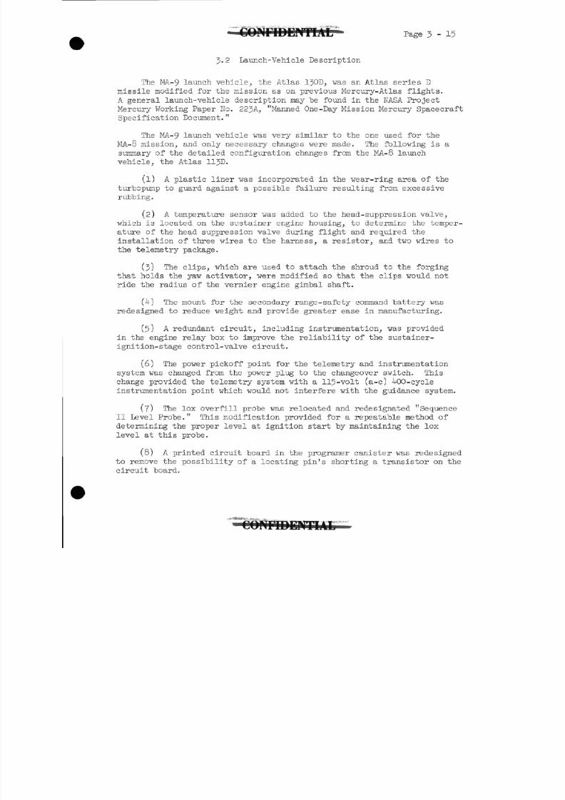
3-2 Launch-Vehicle Description
Page 3-15
The MA-9 launch vehicle, the Atlas 130D, vas an Atlas series D
missile modified for the mission as on previous Mercury-Atlas flights.
A general launch- vehicle description may "befound in the NASA Project
Mercury Working Paper No. 223A, "Manned One-Day Mission Mercury Spacecraft
Specification Document. "
The MA-9 launch vehicle was very similar to the one used for the
MA-8 mission, and only necessary changes were made. The following is a
summary of the detailed configuration changes from the MA-8 launch
vehicle, the Atlas 11JD.
(1) A plastic liner was incorporated in the wear-ring area of the
turbopump to guard against a possible failure resulting from excessive
rubbing.
(2) A temperature sensor was added to the head- suppress ion valve,
which is located on the sustainer engine housing, to determine the temper-
ature of the head suppression valve during flight and required the
installation of three wires to the harness, a resistor, and two wires to
the telemetry package.
(3) The clips, which are used to attach the shroud to the forging
that holds the yaw activator, were modified so that the clips would not
ride the radius of the vernier engine gimbal shaft.
The mount for the secondary range-safety command battery was
redesigned to reduce weight and provide greater ease in manufacturing.
(5) A redundant circuit, including instrumentation, was provided
in the engine relay box to improve the reliability of the sustainer-
ignition-stage control-valve circuit.
(6) The power pickoff point for the telemetry and instrumentation
system was changed from the power plug to the changeover switch. This
change provided the telemetry system with a 115-volt (a-c) -00-cycle
instrumentation point which would not interfere with the guidance system.
(7) The lox overfill probe was relocated and redesignated "Sequence
II Level Probe." This modification provided for a repeatable method of
determining the proper level at ignition start by maintaining the lox
level at this probe.
(8) A printed circuit board in the programer canister was redesigned
to remove the possibility of a locating pin's shorting a transistor on the
circuit board.
8/7/2019 Post Launch Memorandum Report for Mercury-Atlas No. 9(MA-9). Part 1 Mission Analysis
http://slidepdf.com/reader/full/post-launch-memorandum-report-for-mercury-atlas-no-9ma-9-part-1-mission 34/344
P a g e 3 - 16 C O N F I D E N T I A L
(9) The event times for the flight programer were changed to be
compatible vith the staging discretes of the latest launch trajectory.
(a) BECO - 132.9 sec instead of 129-9 sec
(b) Sustainer pitch program duration - 13-5 sec instead
of 16. U sec
(c) Initiation of guidance after BECO - 22.5 sec instead
of 2 .0 sec
(d) SECO - 303.6 sec instead of 305.1 sec
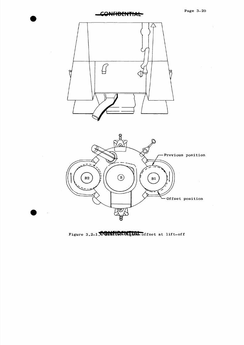
(10) To reduce the possibility of an undesirable lift-off clockwise
roll transient, the booster-engine yaw actuators were offset (see
fig. 3-2-1) as follows to produce a counter-clockwise roll moment:
Booster-engine no. 1 - yaw actuator lengthened by 0.0 ± 0.02inch
Booster-engine no. 2 - yaw actuator shortened by 0.0 ± 0.02
inch
The offsets were checked by the usual level method and by using a new
alinement jig supplied by the engine contractor.
(11) The temperature sensor in the sustainer-engine lubricant tank
was relocated to the aft 20 percent of the tank to provide a temperature
study of the lubricant as it is consumed.
(12) A redundant path to ground was provided for the shielding in
the autopilot harness.
(13) The boat cover in the sustainer engine area was restrained by
a spring which had a tensile strength approximately twice that of the
spring used in the MA-8 launch vehicle. This change was made to provide
better thermal protection of wiring harnesses.
A preflight purge of the boattail area with 100-percent gaseous.
nitrogen was incorporated to reduce the possibility of fire.
(15) The propellent utilization (PU) manometer was calibrated for theAtlas-D tank, rather than for the Atlas-C configuration.
(16) A microswitch which indicates full lox-valve travel was rewired
to permit inclusion in the ignition-stage sequence circuit to reduce the
possibility of a lox-pump failure.
(17) The wiring technique for the autopilot in the flight control
section was modified to improve its overall reliability. These units were
replaced at the factory prior to delivery of the launch vehicle to the launch
site.
8/7/2019 Post Launch Memorandum Report for Mercury-Atlas No. 9(MA-9). Part 1 Mission Analysis
http://slidepdf.com/reader/full/post-launch-memorandum-report-for-mercury-atlas-no-9ma-9-part-1-mission 35/344
SOMflDCNTIALPage
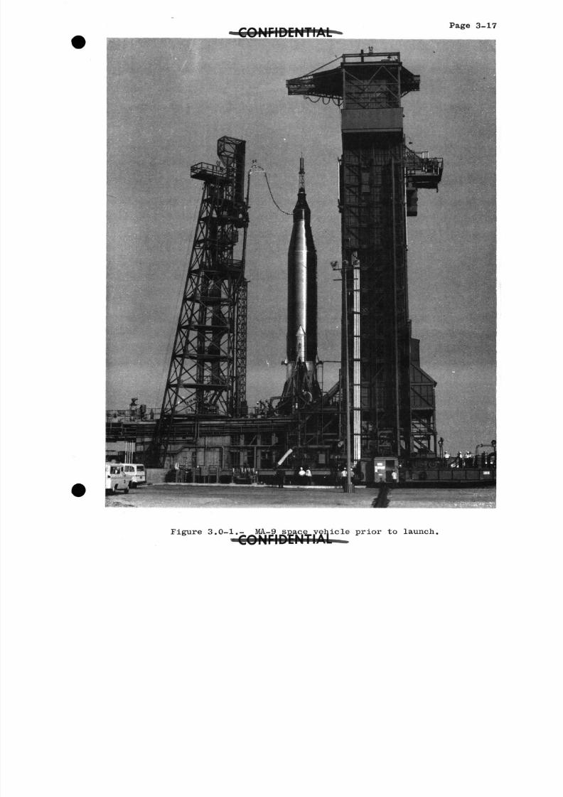
Figure 3.0-1.- MA-9- MA-9 space vehicle prior to launch.
8/7/2019 Post Launch Memorandum Report for Mercury-Atlas No. 9(MA-9). Part 1 Mission Analysis
http://slidepdf.com/reader/full/post-launch-memorandum-report-for-mercury-atlas-no-9ma-9-part-1-mission 36/344
C O N F I D E N T I A LPage 3-
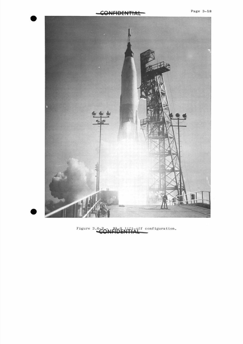
Figure3- 2 K,JVW -.W y off configuration.
8/7/2019 Post Launch Memorandum Report for Mercury-Atlas No. 9(MA-9). Part 1 Mission Analysis
http://slidepdf.com/reader/full/post-launch-memorandum-report-for-mercury-atlas-no-9ma-9-part-1-mission 37/344
3 M E I P E N T I A L Page 3
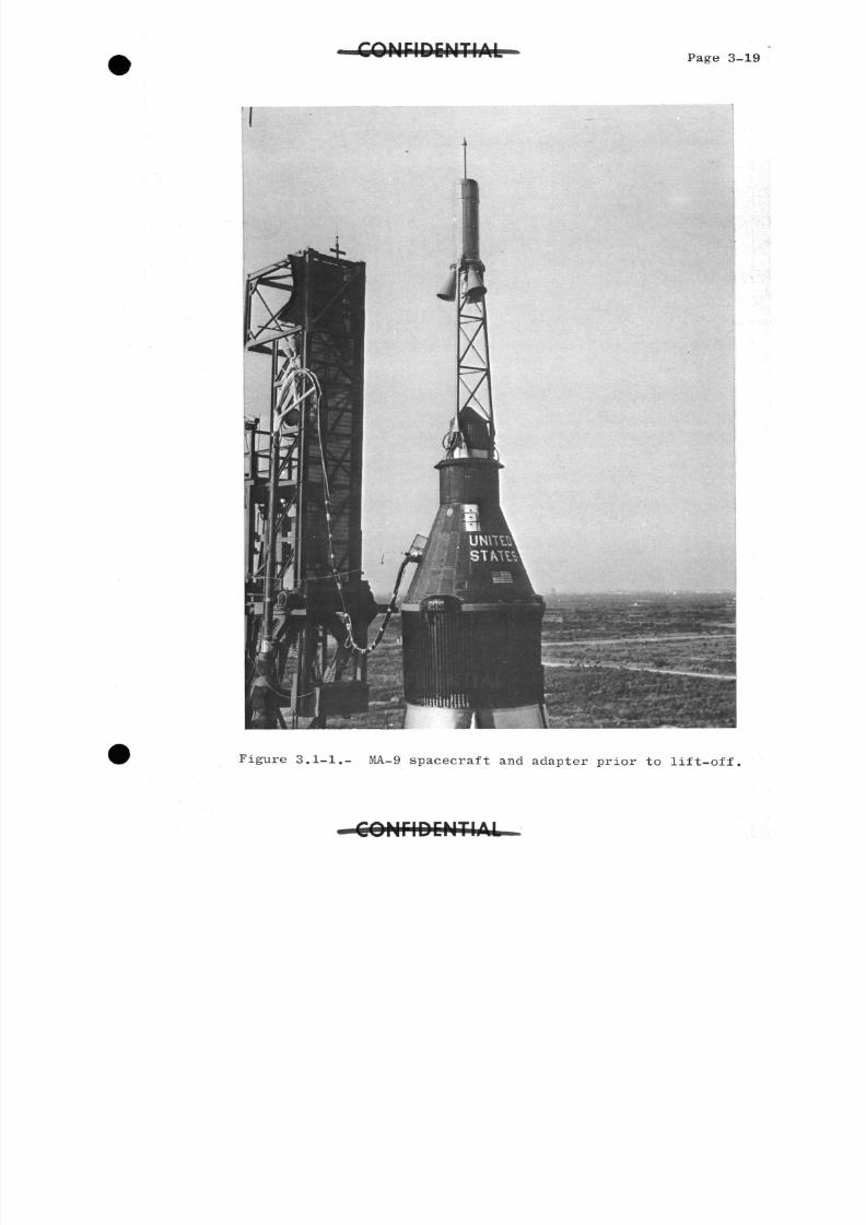
Figure 3.1-1.- MA-9 spacecraft and adapter prior to lift-off,
8/7/2019 Post Launch Memorandum Report for Mercury-Atlas No. 9(MA-9). Part 1 Mission Analysis
http://slidepdf.com/reader/full/post-launch-memorandum-report-for-mercury-atlas-no-9ma-9-part-1-mission 38/344
C O N F I D E N T I A LPage3-20
Previous position
Offset position
8/7/2019 Post Launch Memorandum Report for Mercury-Atlas No. 9(MA-9). Part 1 Mission Analysis
http://slidepdf.com/reader/full/post-launch-memorandum-report-for-mercury-atlas-no-9ma-9-part-1-mission 39/344
Page k - 1
k.O TRAJECTORY AND MISSION EVENTS
Sequence of Flight Events
The times at which the major events of the MA-9 mission occurred
are given in table U.l-1.
8/7/2019 Post Launch Memorandum Report for Mercury-Atlas No. 9(MA-9). Part 1 Mission Analysis
http://slidepdf.com/reader/full/post-launch-memorandum-report-for-mercury-atlas-no-9ma-9-part-1-mission 40/344
Page h - 2
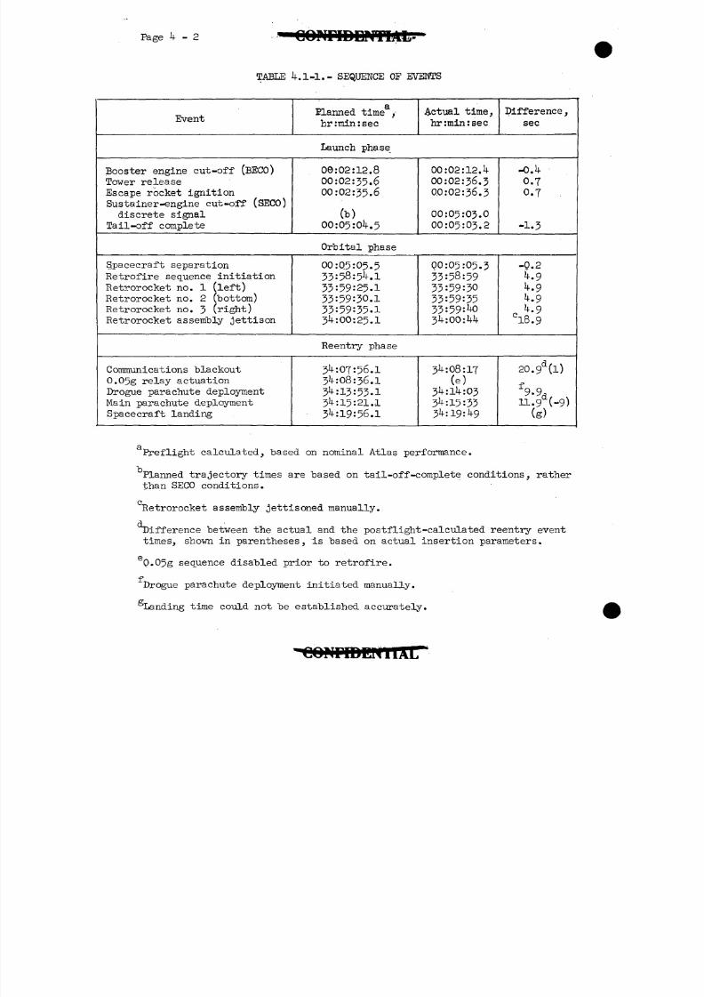
TABLE IK 1-1.- SEQUENCE OF EVENTS
Event
Q
ELanned time ,hr :min : sec
Actual time,hr:min:sec
Difference ,
sec
Launch phase
Booster engine cut-off (BECO)Tower releaseEscape rocket ignitionSustainer-engine cut-off (SECO)discrete signal
Tail -off complete
00:02:12.800:02:35.600:02:35.6
(b)00:05:0 .5
00:02:12. !< •
00:02:36.300:02:36.3
00:05:03.000:05:03.2
-OA
0.70 . 7 .
-1.3
Orbital phase
S/pacecraft separationRetrofire sequence initiationRetrorocket no. 1 (left)Retrorocket no. 2 (bottom)Retrorocket no. 3 (right)Retrorocket assembly jettison
00:05:05.5
33:58:5 .133:59:25.133:59:30.1
33:59:35.13*1:00:25.1
00:05:05.3
33:58:5933:59:30
33:59:3533:59:J>k:OQ:hk
-0.2
.9
.9.9
c^-9C
l8.9
Reentry phase
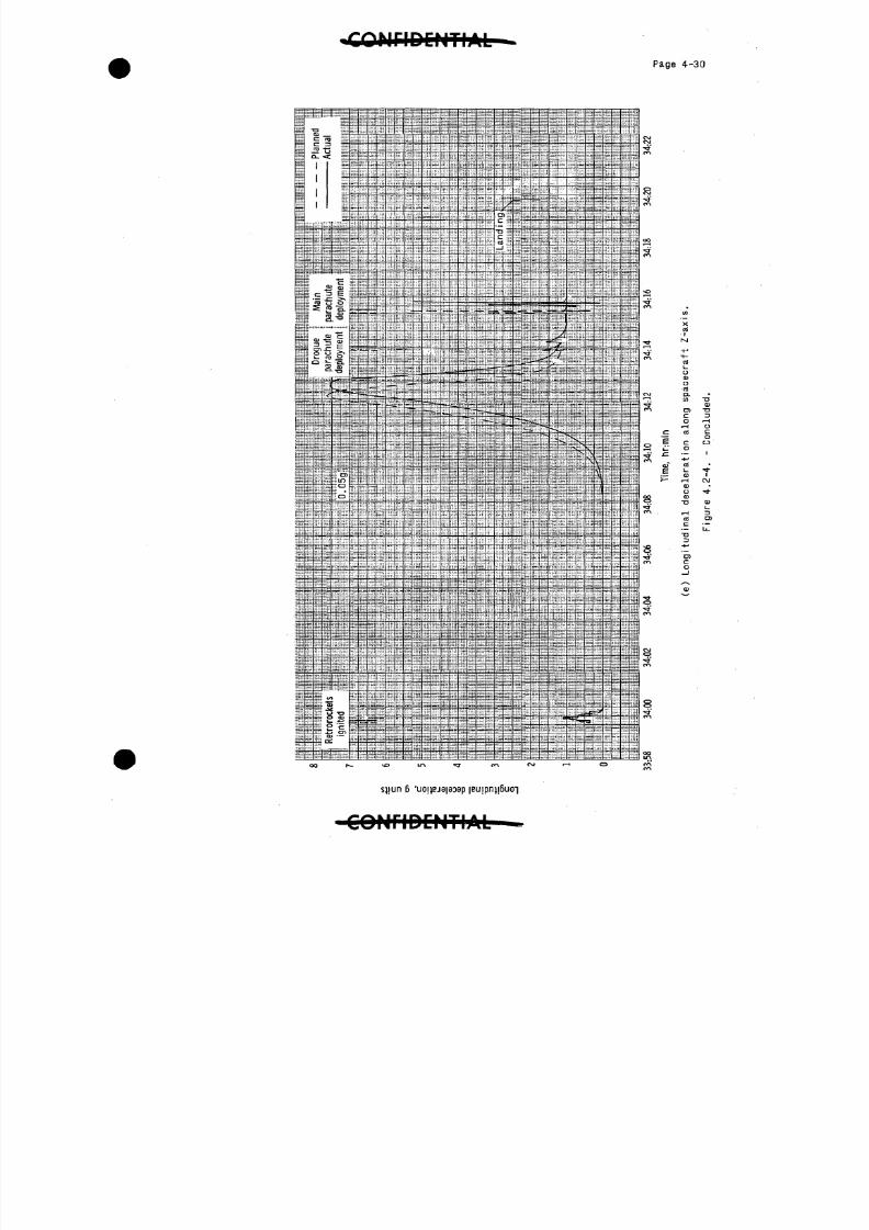
Communications blackout0.05g relay actuation
Drogue parachute deploymentMain parachute deploymentSpacecraft landing
3 :07:56.13 :08:36.1
3 :13:53.13 :15:21.13 :19:56.1
3lv:08:17(e)
3 :1 :033 :15:333li:19:lj.9
20.9d(l)
n.99d(-9)
(g )
Preflight calculated, based on nominal Atlas performance.
Planned trajectory times are based on tail-off-complete conditions, ratherthan SECO conditions.
Ketrorocket assembly jettisoned manually.
Difference between the actual and the postflight-calculated reentry eventtimes, shown in parentheses, is based on actual insertion parameters.
eQ.05g sequence disabled prior to retrofire.
fDrogue parachute deployment initiated manually.
^Landing time could not be established accurately.
8/7/2019 Post Launch Memorandum Report for Mercury-Atlas No. 9(MA-9). Part 1 Mission Analysis
http://slidepdf.com/reader/full/post-launch-memorandum-report-for-mercury-atlas-no-9ma-9-part-1-mission 41/344
Page h - 3
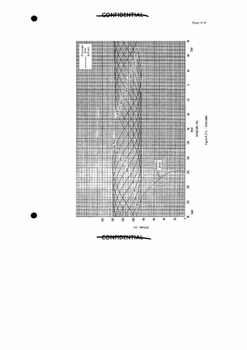
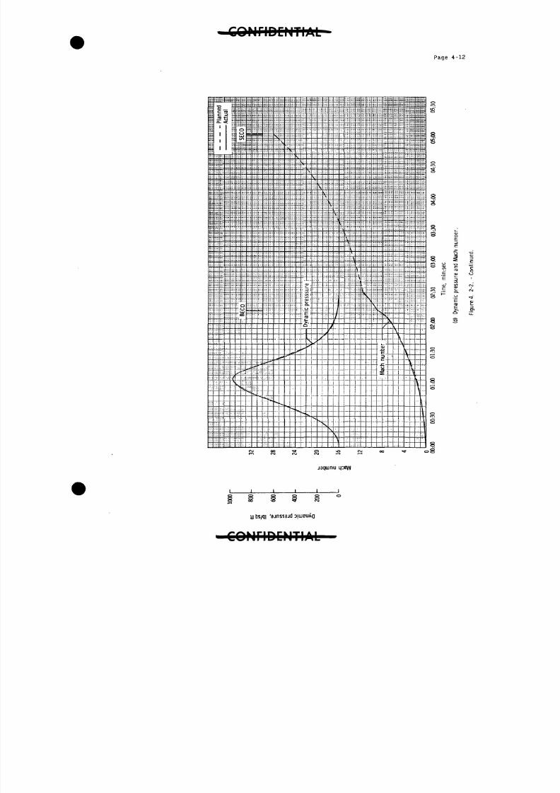
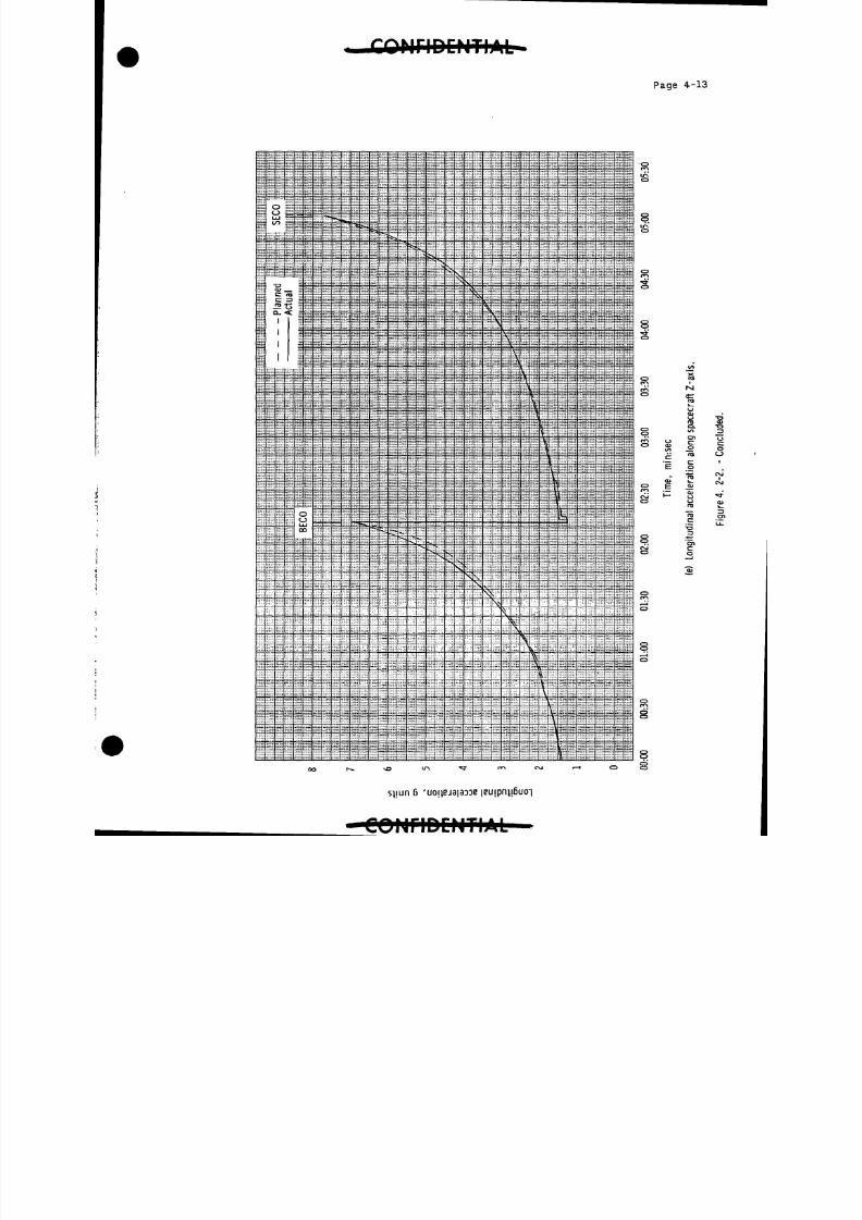
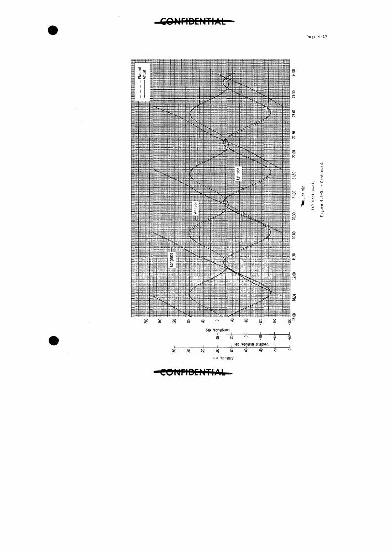
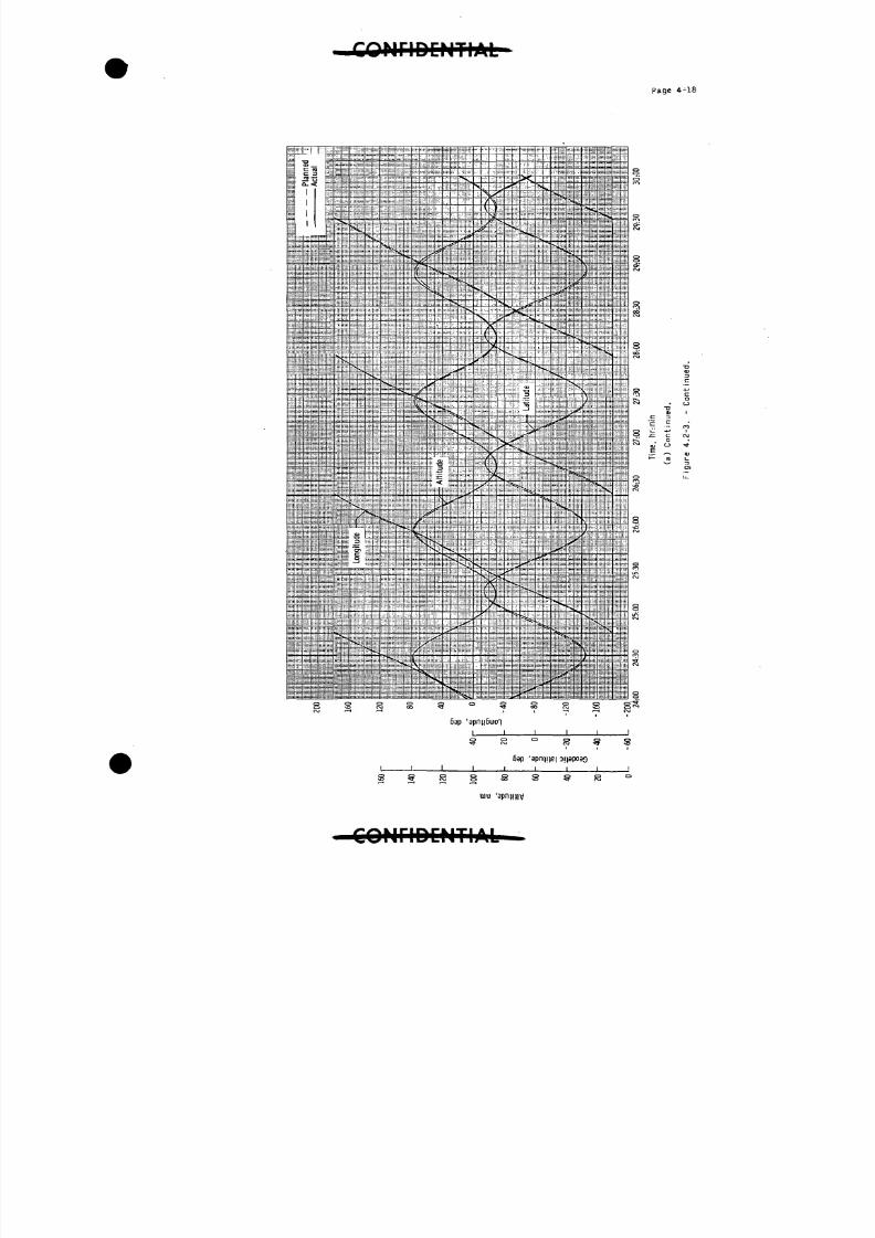
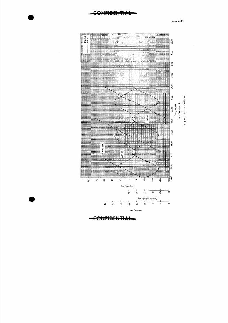
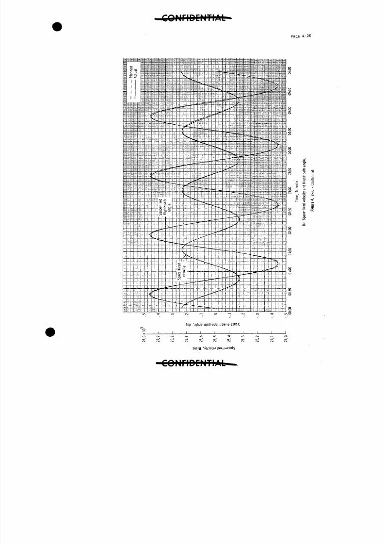
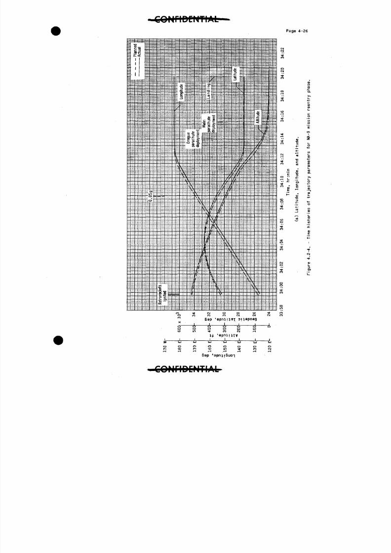
k-,2 Flight Trajectory
The trajectory for the MA-9 flight is discussed in three conven-
ient phases: launch, orbital, and reentry. In all trajectory figures,
the trajectories marked "planned" are preflight-calculated nominal tra-
jectories and the trajectories marked "actual" are based on Mercury net-
work tracking data. The altitude-longitude profile for the entire flight
is presented in figure U.2-1.
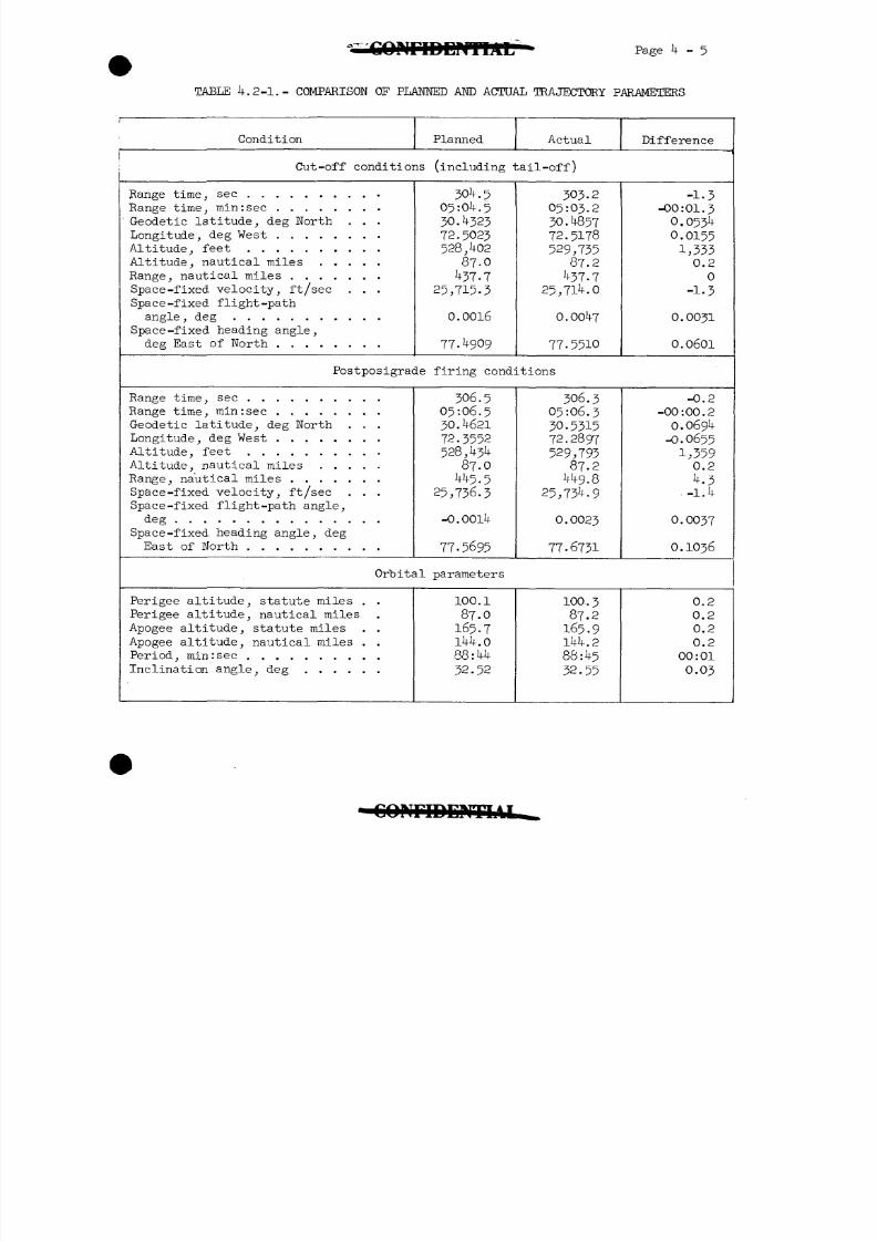
A comparison of the planned and actual trajectory parameters is
given in table .2-1. The differences between the planned and actual
flight trajectory parameters are a result of the actual cut-off conditions
being slightly different than the planned conditions and the atmospheric
density profile on the day of the actual flight being different from that
assumed for the preflight-calculated trajectories.
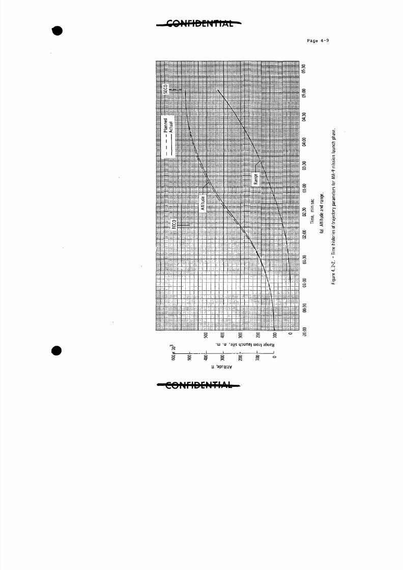
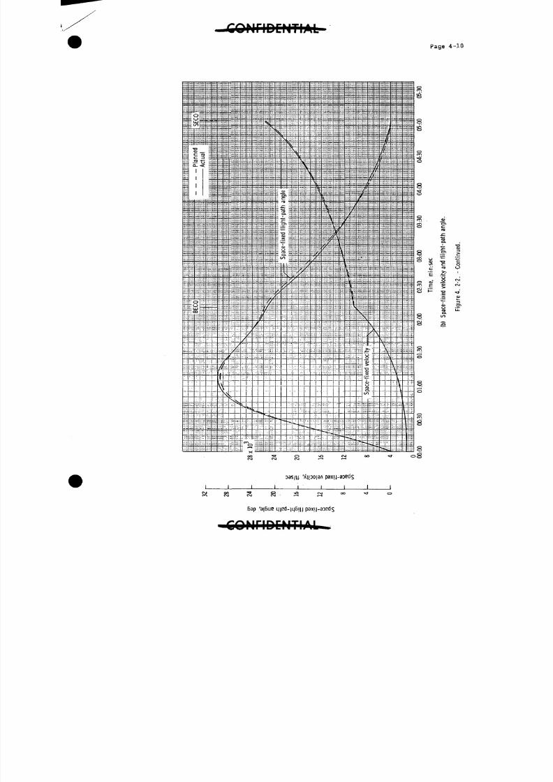
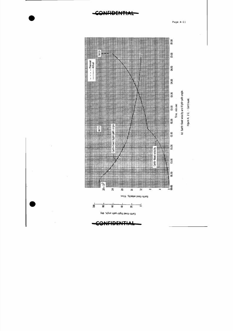
The launch trajectory data shown in figure ^-.2-2 are based on the
real-time output of the Range Safety Impact Predictor Computer (lP-709 -),
which used Azusa MK II and Cape Canaveral FPS-16 radars, and the General
Electric-Burroughs (launch-vehicle guidance) computer. The data from
these tracking facilities were used during the time periods listed in
the following table:
Facility
Cape Canaveral FPS-16
Azusa MK II
General Electric -Burroughs
Elapsed time, minrsec
.0 to 00: 36
00:36 to 01:0
01:0 to 05:55
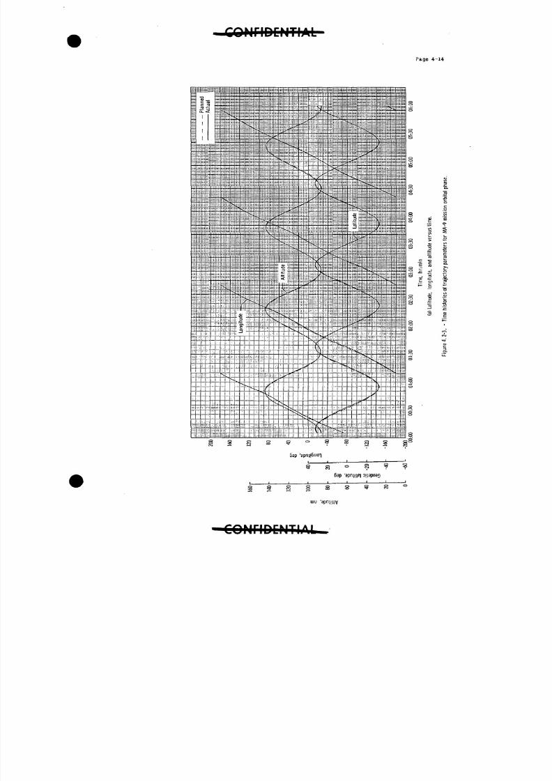
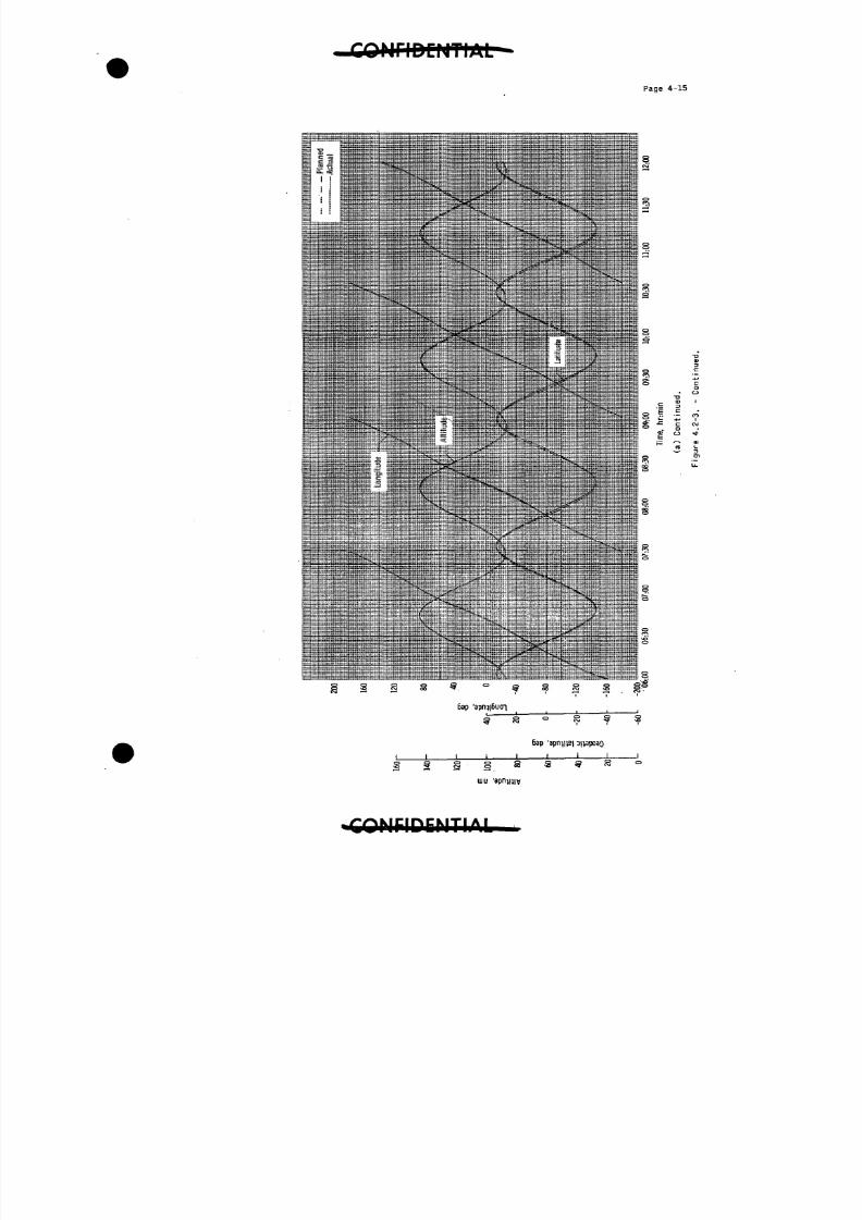
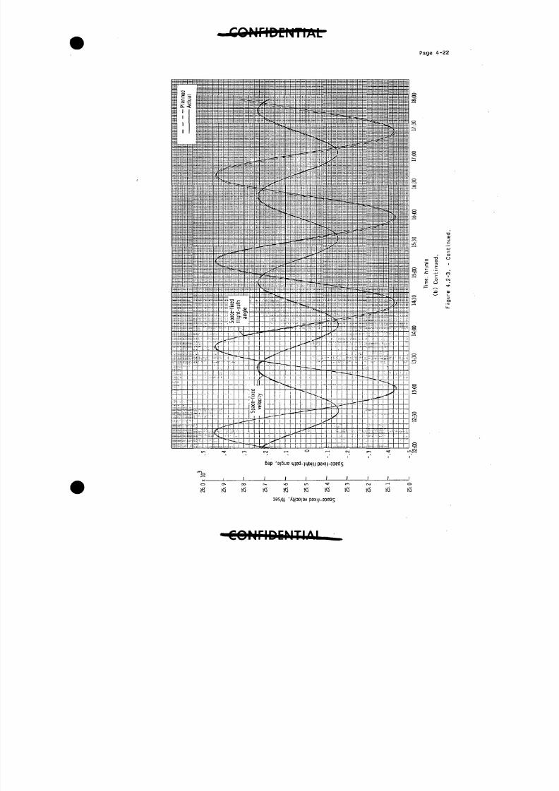
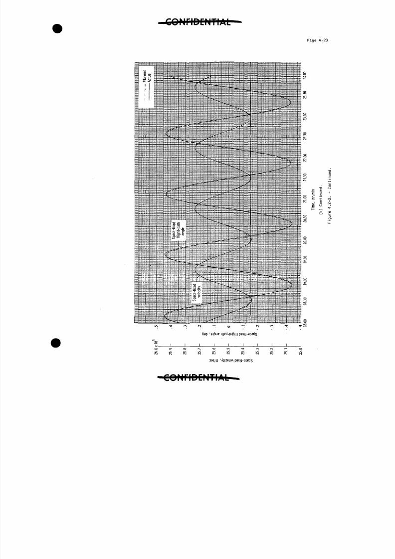
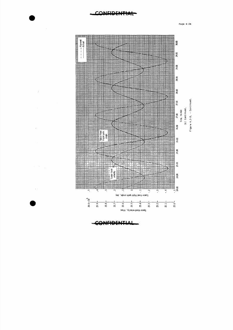
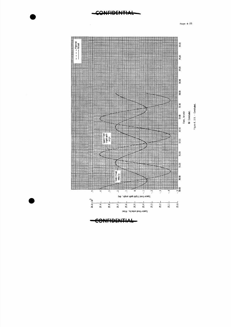
The orbital portion of the trajectory, shown in figure k.2-3, was
derived by starting with the spacecraft position and velocity vector
obtained at the beginning of the second pass over Bermuda, as deter-
mined by the Goddard computer using Mercury network tracking data.
The Bermuda vector was integrated backward along the flight trajectory
to orbital insertion and forward to the time of the Cape Canaveral vector
at the end of the l8th pass. The Cape Canaveral vector was then integrated
forward to the start of retrorocket ignition in the 22nd pass. These inte-
grated values were in good agreement with the values measured by the launch-
vehicle guidance system at orbital insertion. They were also in good agree-ment with the position and velocity vectors determined by the Goddard com-
puter for passes near Eglin Air Force Base, Florida (end of 3rd pass),
Eglin Air Force Base (updated at end of 13th pass), and Cape Canaveral
(end of l8th pass); thus the validity of the integrated orbital portion
of the flight trajectory was established.
C O N F I D E N T I A L "
8/7/2019 Post Launch Memorandum Report for Mercury-Atlas No. 9(MA-9). Part 1 Mission Analysis
http://slidepdf.com/reader/full/post-launch-memorandum-report-for-mercury-atlas-no-9ma-9-part-1-mission 42/344
Page
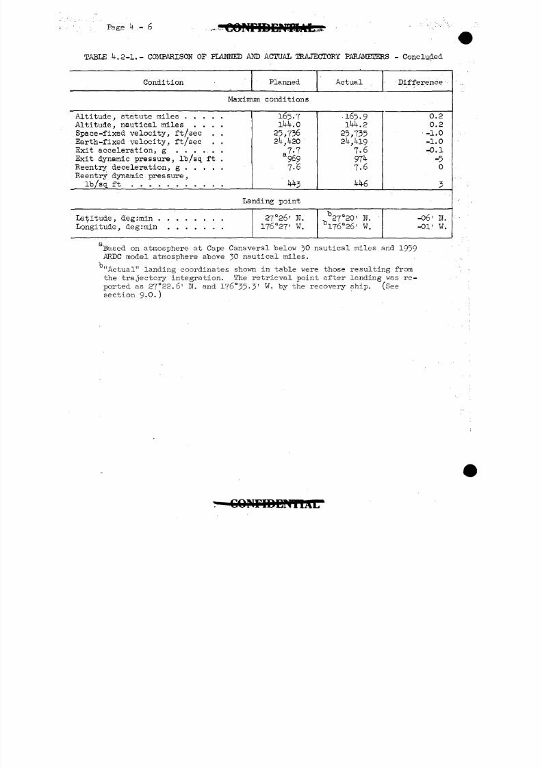
The orbital lifetime of the spacecraft, bas.ed on the 1959 ARDCatmosphere, was calculated to be 92 passes. After nearly 22 passes,the decay in apogee was 7-1 nautical miles and the decay in perigeewas 1.6 nautical miles.
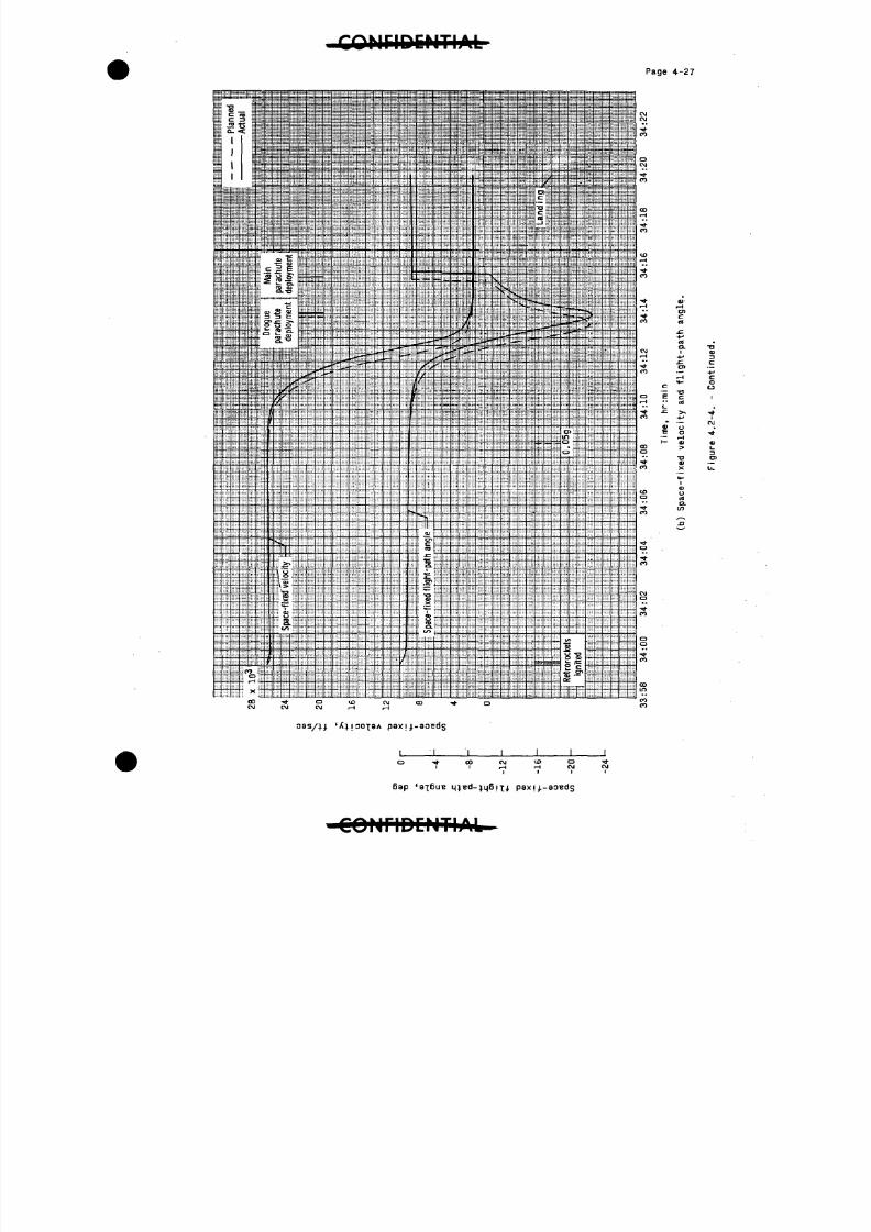
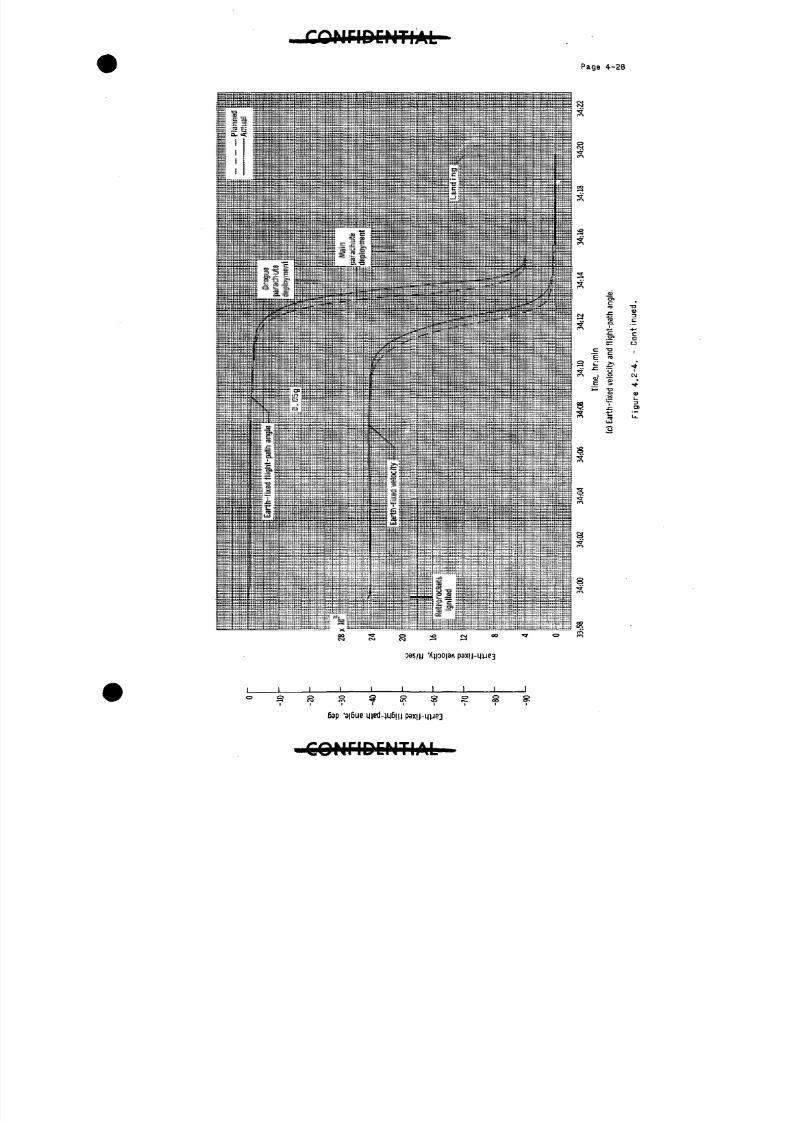
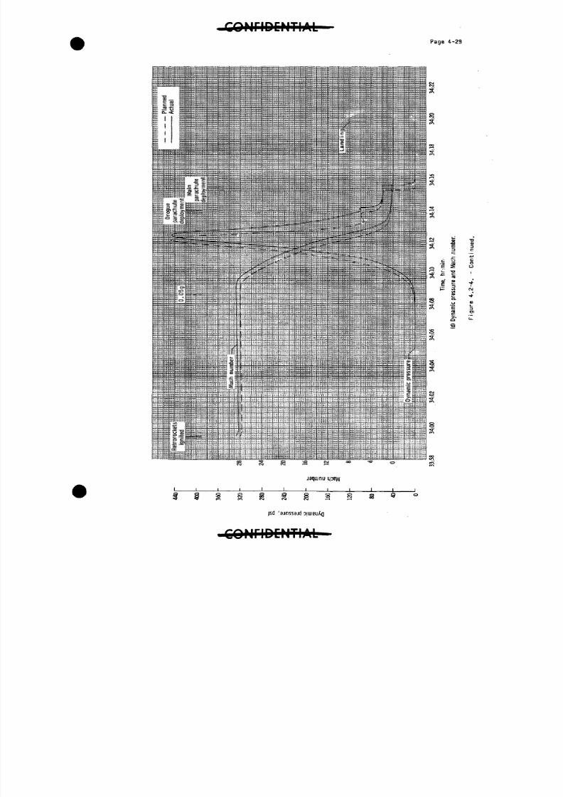
The reentry portion of the trajectory, shown in figure 4-.2-4, wasderived by starting with the spacecraft position and velocity vector,as determined by the Goddard computer, obtained at the end of thel8th orbital pass near Cape Canaveral, Florida. Integrating forwardalong the flight path to retrorocket ignition and,after introducingnominal retrofire conditions, continuing the integration through space-•craft landing yielded the reentry trajectory. Nominal retrofire condi-tions include a retrorocket total impulse of 38,975 l^-sec at spacecraftattitudes of -34° in pitch and 0° in roll and yaw. The spacecraft weightat retrofire was estimated to be 2,979 pounds by using data obtained fromthe. Mercury network stations. The times of communications blackout andmain-parachute deployment from the integrated reentry trajectory were ingood agreement with data from the Mercury network stations and the space-craft onboard measurements. In addition, the landing point from theintegrated trajectory was in good agreement with the retrieval pointreported by the recovery ship. The agreement in these events serve toconfirm the validity of the integrated reentry portion of the flighttrajectory.
8/7/2019 Post Launch Memorandum Report for Mercury-Atlas No. 9(MA-9). Part 1 Mission Analysis
http://slidepdf.com/reader/full/post-launch-memorandum-report-for-mercury-atlas-no-9ma-9-part-1-mission 43/344
Page k - 5
TABLE IK 2-1.- COMPARISON OF PLANNED AND ACTUAL TRAJECTORY PARAMETERS
Condition Planned Actual Difference
Cut-off conditions (including tail-off)
Range time min°secGeodetic latitude , deg North . . .
Longitude deg WestAltitude feet
Altitude nautical miles
Space -fixed velocity, ft/sec . . .
Space -fixed flight -path
Space -fixed heading angle,deg East of North
3014,505:0*4-.5
30.432372.5023
528,l4-02
87.0
437.7
25,715.3
0.0016
77.4909
303.2
05:03.2
30.1t857
72.5178
529,73587.2
437.725,714.0
O . O Q l i - 7
77-5510
-1-3-00:01.3
0.053U
0.0155
1,3330.2
0
-1.3
0.0031
0.0601
Postposigrade firing conditions
Range time sec
Range time mint sec ........Geodetic latitude, deg North . . .Longitude deg West
Altitude feetAltitude nautical miles
Range, nautical milesSpace-fixed velocity, ft/sec . . .
Space-fixed flight-path angle,des ..
Space-fixed heading angle, degEast of North
306.505:06.530.11-621
72.3552528,434
87.0
445.525,736.3
-0.0014
77.5695
306.3
05:06.3
30.531572.2897
529,79387.2
1+49.825,734.9
0.0023
77.6731
-0.2
-00:00.2
0.0694
-0.0655
1,3590.2
4.3.-1.14-
0.0037
0.1036
Orbital parameters
Perigee altitude, statute miles . .
Perigee altitude, nautical miles
Apogee altitude , statute miles . .
Apogee altitude, nautical miles . .Period, min:sec
Inclination angle deg
100.1
87.0165.7
i44.o88:1(432.52
100, 3
87.2165.9144.288:45
32.55
0.2
0.2
0.2
0.200:01
0.03
8/7/2019 Post Launch Memorandum Report for Mercury-Atlas No. 9(MA-9). Part 1 Mission Analysis
http://slidepdf.com/reader/full/post-launch-memorandum-report-for-mercury-atlas-no-9ma-9-part-1-mission 44/344

8/7/2019 Post Launch Memorandum Report for Mercury-Atlas No. 9(MA-9). Part 1 Mission Analysis
http://slidepdf.com/reader/full/post-launch-memorandum-report-for-mercury-atlas-no-9ma-9-part-1-mission 45/344
P a g e 4 - 7
£ =
uiu '
8/7/2019 Post Launch Memorandum Report for Mercury-Atlas No. 9(MA-9). Part 1 Mission Analysis
http://slidepdf.com/reader/full/post-launch-memorandum-report-for-mercury-atlas-no-9ma-9-part-1-mission 46/344
8/7/2019 Post Launch Memorandum Report for Mercury-Atlas No. 9(MA-9). Part 1 Mission Analysis
http://slidepdf.com/reader/full/post-launch-memorandum-report-for-mercury-atlas-no-9ma-9-part-1-mission 47/344
8/7/2019 Post Launch Memorandum Report for Mercury-Atlas No. 9(MA-9). Part 1 Mission Analysis
http://slidepdf.com/reader/full/post-launch-memorandum-report-for-mercury-atlas-no-9ma-9-part-1-mission 48/344
> N r i D C M T I A L
P a g e 4-10
S.
.a- i
oO
-
a "-*
1
CVJ C\J
j I
B a p '3|6ue M (E
CONriDCMTIAl
8/7/2019 Post Launch Memorandum Report for Mercury-Atlas No. 9(MA-9). Part 1 Mission Analysis
http://slidepdf.com/reader/full/post-launch-memorandum-report-for-mercury-atlas-no-9ma-9-part-1-mission 49/344
C O N F I D E N T I A L
P a g e 4-11
s
6 a p
8/7/2019 Post Launch Memorandum Report for Mercury-Atlas No. 9(MA-9). Part 1 Mission Analysis
http://slidepdf.com/reader/full/post-launch-memorandum-report-for-mercury-atlas-no-9ma-9-part-1-mission 50/344
C O N F I D E N T I A L
P a g e 4-12
S 11 1
o iZ
jaqiunu
H bs/q| 'ajnssajdD JU
8/7/2019 Post Launch Memorandum Report for Mercury-Atlas No. 9(MA-9). Part 1 Mission Analysis
http://slidepdf.com/reader/full/post-launch-memorandum-report-for-mercury-atlas-no-9ma-9-part-1-mission 51/344
P a g e 4-13
M
5
-8 5 <?.2 °
J
Q3 '
S £
3
-i
6'
C O N F I D E N T I A L -
8/7/2019 Post Launch Memorandum Report for Mercury-Atlas No. 9(MA-9). Part 1 Mission Analysis
http://slidepdf.com/reader/full/post-launch-memorandum-report-for-mercury-atlas-no-9ma-9-part-1-mission 52/344
CONFIDENTIAL
-op(ato •F- 1 t-- "
a.=-fe
•*- o
- a 5
6 a p ' _iii-i
6 a p 'epnmei o
1 -1
g S °
m u '
8/7/2019 Post Launch Memorandum Report for Mercury-Atlas No. 9(MA-9). Part 1 Mission Analysis
http://slidepdf.com/reader/full/post-launch-memorandum-report-for-mercury-atlas-no-9ma-9-part-1-mission 53/344
QNriDCNTIAL
P a g e 4-15
w u '
-/"/"MllCIPlCMTIAI

8/7/2019 Post Launch Memorandum Report for Mercury-Atlas No. 9(MA-9). Part 1 Mission Analysis
http://slidepdf.com/reader/full/post-launch-memorandum-report-for-mercury-atlas-no-9ma-9-part-1-mission 54/344
ff\±tPI I*N f kUJA-I
P a g e 4-16
A I
8/7/2019 Post Launch Memorandum Report for Mercury-Atlas No. 9(MA-9). Part 1 Mission Analysis
http://slidepdf.com/reader/full/post-launch-memorandum-report-for-mercury-atlas-no-9ma-9-part-1-mission 55/344
C O N F I D E N T I A L
P a g e 4-17
S £
6 a p 'apnn6u<r|
6 a p
S § 8 S S
uiu 'apn)j) iv
8/7/2019 Post Launch Memorandum Report for Mercury-Atlas No. 9(MA-9). Part 1 Mission Analysis
http://slidepdf.com/reader/full/post-launch-memorandum-report-for-mercury-atlas-no-9ma-9-part-1-mission 56/344
Q N r i D C M T I A L
P a g e 4-18
E .^
8 8
6 a p '9pn||6uo~|
S
6 a p '
j I
S 8 S
m u '
8/7/2019 Post Launch Memorandum Report for Mercury-Atlas No. 9(MA-9). Part 1 Mission Analysis
http://slidepdf.com/reader/full/post-launch-memorandum-report-for-mercury-atlas-no-9ma-9-part-1-mission 57/344
O N F I D E N T I A L
P a g e 4-19
3
g s
L U U '
8/7/2019 Post Launch Memorandum Report for Mercury-Atlas No. 9(MA-9). Part 1 Mission Analysis
http://slidepdf.com/reader/full/post-launch-memorandum-report-for-mercury-atlas-no-9ma-9-part-1-mission 58/344
^ C O N F I D E N T I A L
P a g e 4- 2 0
S' cC = o
1V
sa
6 a p ' a |6ue
J I
oo esi CM CM CM CM CM
C O H r i D C N T I A f c .

8/7/2019 Post Launch Memorandum Report for Mercury-Atlas No. 9(MA-9). Part 1 Mission Analysis
http://slidepdf.com/reader/full/post-launch-memorandum-report-for-mercury-atlas-no-9ma-9-part-1-mission 59/344
8/7/2019 Post Launch Memorandum Report for Mercury-Atlas No. 9(MA-9). Part 1 Mission Analysis
http://slidepdf.com/reader/full/post-launch-memorandum-report-for-mercury-atlas-no-9ma-9-part-1-mission 60/344
P a g e 4 - 2 2
8
6a p ' 3 |6ue
D3S/1J '
8/7/2019 Post Launch Memorandum Report for Mercury-Atlas No. 9(MA-9). Part 1 Mission Analysis
http://slidepdf.com/reader/full/post-launch-memorandum-report-for-mercury-atlas-no-9ma-9-part-1-mission 61/344
P a g e 4-2 3
6 a p
S3'
C O M r i D E H T I A L -
8/7/2019 Post Launch Memorandum Report for Mercury-Atlas No. 9(MA-9). Part 1 Mission Analysis
http://slidepdf.com/reader/full/post-launch-memorandum-report-for-mercury-atlas-no-9ma-9-part-1-mission 62/344
P a g e 4-24
<1 > °E "
S ap 'a|6ue i|}ed-in6j|j pax i j -aoeds
- a o e d s
AI
8/7/2019 Post Launch Memorandum Report for Mercury-Atlas No. 9(MA-9). Part 1 Mission Analysis
http://slidepdf.com/reader/full/post-launch-memorandum-report-for-mercury-atlas-no-9ma-9-part-1-mission 63/344
O N F I D E N T I A L
P a g e 4-25
Sa p ' 3 |6ue med-(i|6iu pax i j -aoeds
i i I I I L
uS ir» LTl lf\CM CM CM CM CM
D 3 S / U 'A }
C Q N r i D H N T I A L
8/7/2019 Post Launch Memorandum Report for Mercury-Atlas No. 9(MA-9). Part 1 Mission Analysis
http://slidepdf.com/reader/full/post-launch-memorandum-report-for-mercury-atlas-no-9ma-9-part-1-mission 64/344
£OHriDCNTIAL
P a g e 4-26
COas
in »« S B•D f
S Ii _
m 01•S 0-
^ 0)" )
K)
5 H-._ O
S s^« o
L.3CD
o1
OCO
Of--
OLO
O
CO
O
CM
Ba p
• C O N r i D C H T I A L
8/7/2019 Post Launch Memorandum Report for Mercury-Atlas No. 9(MA-9). Part 1 Mission Analysis
http://slidepdf.com/reader/full/post-launch-memorandum-report-for-mercury-atlas-no-9ma-9-part-1-mission 65/344
8/7/2019 Post Launch Memorandum Report for Mercury-Atlas No. 9(MA-9). Part 1 Mission Analysis
http://slidepdf.com/reader/full/post-launch-memorandum-report-for-mercury-atlas-no-9ma-9-part-1-mission 66/344
8/7/2019 Post Launch Memorandum Report for Mercury-Atlas No. 9(MA-9). Part 1 Mission Analysis
http://slidepdf.com/reader/full/post-launch-memorandum-report-for-mercury-atlas-no-9ma-9-part-1-mission 67/344
P a g e 4-29
• I i
jaqiunu
S i § S SCM C\J CSJ i»
js d 'ajnssajd o m
§
caCJ
8/7/2019 Post Launch Memorandum Report for Mercury-Atlas No. 9(MA-9). Part 1 Mission Analysis
http://slidepdf.com/reader/full/post-launch-memorandum-report-for-mercury-atlas-no-9ma-9-part-1-mission 68/344
/•Klr*lrvr*
P a g e 4 - 3 0
oniCLW T3
O >
CO ~OC 3O tHi-H O
nS CO
C OO I
oa>
T3
ni CD
C
D>CO
sjiun 6 'u o
G O N r i D C N T I A L
8/7/2019 Post Launch Memorandum Report for Mercury-Atlas No. 9(MA-9). Part 1 Mission Analysis
http://slidepdf.com/reader/full/post-launch-memorandum-report-for-mercury-atlas-no-9ma-9-part-1-mission 69/344
TIDCNTIAL •*»Pa
§e
5 -
5. 0 SPACECRAFT P E R F O R M A N C E
The spacecraft as an entity performed adequately. Some system
anomalies were experienced, and analyses of these are discussed in the
following paragraphs. Also discussed, from an overall mission viewpoint,are the spacecraft systems' general performance. In addition, a descrip-
tion of each spacecraft system is presented. This description is pre-
sented in terms of the major changes made since the MA-8 mission, and
reference should be made to section 3-1, Spacecraft Description, for a
listing of all significant spacecraft changes.
5-1 Spacecraft Control System
All spacecraft control system components functioned normally until
approximately 28:3 :3 .> at which time the 0.05g relay circuit was actuated.
The astronaut did not report this event on the onboard tape until approxi-mately 28:59-'00. The .reason for this delay in reporting was twofold:
1. The control mode at the time of 0. 05g relay activation was manual
proportional with gyros caged, and
2. The spacecraft warning lights switch was in the off position
because the astronaut was engaged in taking photographs.
When the warning lights switch was placed in the dim position, the
0.05g green light was noted. From 28:3 :3 until the end of the mission,
the amplifier-calibrator (amp-cal) was locked in the 0.05g configuration.
Operation of the automatic stabilization and control system in this con-figuration resulted in damping about the pitch and yaw axes and in a
-12°/sec rate command in the roll axis unless one of the manual control
modes was selected.
5-1.1 System description.- The spacecraft control system is designed
to provide stabilization and orientation of the spacecraft from
immediately following spacecraftlaunch-vehicle separation until
deployment of the main parachute. The system is capable of
operation in the following modes:
1. Automatic stabilization and control system (ASCS) with
alternatives of orientation, orbit, and auxiliary damping modes.
2. Fly-by-wire (FB¥), which is an electrical "on-off"
command of the automatic reaction control system (RCS) thrusters
initiated by the astronaut's control stick. Astronaut's choice
of high and low thrusters or low thrusters only (FEW low) is
available.
3. Manual proportional (MP), which is a mechanical command
of the manual RCS thrusters initiated by the astronaut's control
stick.
V^Vr.1T.TJI-LrEjl M.'M.£ L ^ ^
8/7/2019 Post Launch Memorandum Report for Mercury-Atlas No. 9(MA-9). Part 1 Mission Analysis
http://slidepdf.com/reader/full/post-launch-memorandum-report-for-mercury-atlas-no-9ma-9-part-1-mission 70/344
p a g e 5 - 2
Modes 1 and 2 utilize the automatic ECS fuel supply, while mode3 utilizes the manual RCS fuel supply. Combinations of modes1 and 3 or 2 and 3-are available to provide "double authority"at the astronaut's discretion.
Major changes made to the control system since the previousmission are as follows: the vertical attitude gyro was modifiedto provide the capability to cage and uncage at -3 °, whichsimplified the astronaut's task in alining the gyros to retro-attitude (orbit attitude); the rate stabilization and controlsystem (RSCS) was removed to reduce weight; the ASCS rate gyroswere rewired to run continuously when the ASCS was powered upuntil antenna fairing separation; the ASCS mode switch was changedto provide a means of deenergizing the automatic RCS solenoidcircuitry; a horizon-scanner power circuit was incorporated intothe attitude gyro switch, which powered up the scanners only whenin the "slave" position; and a JO-second time delay was added to
the horizon-scanner slaving circuitry to allow time for scannerwarm-up.
5.1.2 Performance analysis.- The performance of the spacecraft controlsystem was completely satisfactory during the first l8 orbitalpasses. Outputs of the gyros and the horizon scanners agreed towithin 2° during the periods of scanner slaving.
The ASCS orbit mode limit cycles in the pitch, roll, and yaw axeswere relatively balanced; that is, there were an equal number ofpulses on both sides of attitude gyro null. For the greaterpor-tion of operation in the ASCS mode, the yaw-axis limit cycle
reached +10° in periods of less than 3 minutes. However, moreactivity in this axis was expected because of the cross-couplingeffect between the roll and yaw slaving circuitry. The averagelimits of the roll axis cycle were ±8.5% and the limits of thepitch axis cycle were +7°. As was noted during the MA-8mission,pulse durations were not sufficient to limit the orbit cycle towithin the more desirable ±5.5°- However, this condition is notconsidered to be detrimental and does not appreciably increasefuel consumption.
At 28:3 :3 ; the 0.05g relay circuit actuated and locked in. Atapproximately 29:^9tOO? "the astronaut powered up the ASCS bus and
verified that the amplifier-calibrator was in the 0.05g configu-ration by noting that the attitude indicators would not respondto spacecraft attitude changes. He then made a reentry roll ratecheck at about 31:17'-00 and verified that the ASCS would functionnormally in the 0.05g logic circuit during reentry. However,planned use of the ASCS for reentry was abandoned at about 33:07:00
when it became evident that the ASCS bus was not receiving powerfrom either the ASCS a-c main inverter or the standby a-c inverter.
CONFIDi
8/7/2019 Post Launch Memorandum Report for Mercury-Atlas No. 9(MA-9). Part 1 Mission Analysis
http://slidepdf.com/reader/full/post-launch-memorandum-report-for-mercury-atlas-no-9ma-9-part-1-mission 71/344
8/7/2019 Post Launch Memorandum Report for Mercury-Atlas No. 9(MA-9). Part 1 Mission Analysis
http://slidepdf.com/reader/full/post-launch-memorandum-report-for-mercury-atlas-no-9ma-9-part-1-mission 72/344
p a g e 5 - * O O M T D D P i T I A L tner*
The shorting and charring of the power plug and the 0.05g relay •circuit actuation occurred independently; however, both mal-functions apparently resulted from the presence of moisture.
5-1.^ Control system -utilization.- Immediately after spacecraft
separation at 00:05:0^, the astronaut switched to the auxiliarydamping mode for k seconds. At 00:05:1? he began to executethe yaw turnaround maneuver by using the fly-by-wire lowthrusters. By 00:08:33> the turnaround maneuver was completedand the control system was placed in the ASCS orbit mode. Thismode was employed for approximately 15 percent of the time thatspacecraft power was utilized. Fly-by-wire low was used forextended maneuvers and experiments almost exclusively through-out the mission; and, therefore, a minimum usage of the auto-matic RCS fuel supply resulted. Only one automatic high thrusterwas actuated during the orbital phase of the mission, except fort h e momentary high thruster action in the auxiliary damping mode
after spacecraft separation. The negative roll high thrust unitwas utilized prior to retrofire during the epecial 0.05g testat about 31:17:00.
Attitudes for retrofire were maintained by using the manualproportional mode, with fly-by-wire high and low ready as abackup. The astronaut maintained the spacecraft attitudesextremely well during the retrofire period, as was evidencedby the spacecraft's proximity to the planned landing position.Control during reentry was maintained by using the manualproportional and fly-by-wire modes simultaneously. The maximumthrust of ^9 pounds about the pitch and yaw axes was used by
the astronaut in maintaining control during reentry.
5.1.5 Reaction control system.- The major changes made to thereaction control system (RCS) since the previous missioninclude the addition of a 15-pound capacity hydrogen-peroxidetank (see fig. 5-1-5-1) in parallel to the automatic system,the removal of poppets and springs from the check valve atthe outlet of each fuel tank, the incorporation of an RCS inter-connect valve between the automatic and manual fuel system, theinstallation of a main instrument panel indicator to enable theastronaut to monitor regulated nitrogen pressure for both thefuel systems, and an increase in the wall thickness of the
expulsion tubes for the fuel tanks from 0.062 inch to 0.125 inch.
An analysis of the onboard data confirmed the astronaut's reportof satisfactory performance of the RCS throughout the flight.
One instance of thruster "tail-off" in the yaw-right manualthruster was noted by the astronaut. The incident occurredapproximately 13 hours after lift-off during a flight period
8/7/2019 Post Launch Memorandum Report for Mercury-Atlas No. 9(MA-9). Part 1 Mission Analysis
http://slidepdf.com/reader/full/post-launch-memorandum-report-for-mercury-atlas-no-9ma-9-part-1-mission 73/344
-fiDMflDENTIAL -
for which no onboard data are available. A postlaunch
evaluation of this minor anomaly indicates no reason for
this action.
The astronaut reported that he had intended to use FEW for
reentry but that the FEW pitch-up high thruster was slowto light off, and therefore, he selected manual proportional.
An analysis of the onboard data indicates that the FEW pitch-
up high-thruster command was maintained only 0.2 second and
that thruster operation for this brief period was normal. This
short pulse duration, in conjunction with the fact that there
had been no previous use of the high thruster to achieve thrust
chamber warm-up, probably reduced the pilot's confidence in
the FEW mode and led him to elect "double authority" control
during reentry.
The amount of fuel used during the mission is shown in
table 5-1-5-1- Approximately 7 pounds of manual fuel and21 pounds of automatic fuel were jettisoned after reentry.
Fuel supply pressure readings varied during the mission because
of cabin temperature changes, with the automatic system trans-
ducer being affected the most.
Fuel jettison was initiated after reentry as planned at approxi-
mately 3 :15:55- The total time required to jettison the re-
maining fuel from the automatic and manual systems was approxi-
mately 1 minute and 33 seconds. The RCS interconnect valve
was utilized to permit the manual system fuel to jettison
through the automatic system pitch and yaw high thrust chambers.
Solenoid-valve inlet temperatures for the 1-pound yaw-left,
the 1-pound pitch-down, and the 1-pound roll-clockwise thrust
chamber assemblies in the automatic RCS were measured during
the flight and are shown in figure 5-1-5-2. The maximum
temperature at the solenoid inlet recorded during the orbital
phase was approximately 103° F. This temperature was measured
for the 1-pound roll-clockwise thruster at 11:20:00. The
minimum temperature recorded was approximately 53° F and was
measured for the 1-pound pitch-down thruster at approximately
22:30:00.
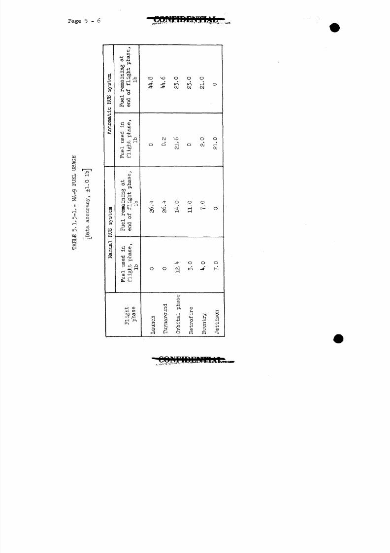
8/7/2019 Post Launch Memorandum Report for Mercury-Atlas No. 9(MA-9). Part 1 Mission Analysis
http://slidepdf.com/reader/full/post-launch-memorandum-report-for-mercury-atlas-no-9ma-9-part-1-mission 74/344
8/7/2019 Post Launch Memorandum Report for Mercury-Atlas No. 9(MA-9). Part 1 Mission Analysis
http://slidepdf.com/reader/full/post-launch-memorandum-report-for-mercury-atlas-no-9ma-9-part-1-mission 75/344
8/7/2019 Post Launch Memorandum Report for Mercury-Atlas No. 9(MA-9). Part 1 Mission Analysis
http://slidepdf.com/reader/full/post-launch-memorandum-report-for-mercury-atlas-no-9ma-9-part-1-mission 76/344
5 - 8
In addition to system changes to accommodate the extended flight,
other modifications from the spacecraft 16 (MA-8) configuration
were required to improve system performance. The major changes
in this category are discussed in the following paragraphs.
Because of the partial blockage problem experience in MA-8, asuit bypass CCV was installed in parallel with the existing CCV
for redundancy.
A condensate trap, shown in figure 5-2.1.1-1, was installed at
the suit-inlet port to extract free condensate water which would
adhere to the inner wall of the water separator and thus escape
extraction. The inner wall of this trap was a wicking material,
which has the property of passing water, but not gas, when the
material is wet.
The cabin-pressure relief valve was equipped with a water sealing
device to enable the astronaut to lock this valve and prevent
sea water from entering the spacecraft after landing.
A sensor for measuring carbon-dioxide partial pressure (PCO ) was
installed in the suit circuit to indicate CO concentration and
actuate a warning tone and light at a PCO value of 8 mm Hg.
The suit inlet for emergency oxygen flow was repositioned upstream
of the PCO sensor, and thereby permitted a purging of the PCO
sensor with 100-percent oxygen to verify its operation.
The suit-circuit, from the water-separator to the junction with
the suit-inlet flexible hose, was insulated to reduce, heat loss;
and the LiOH canister was insulated to minimize condensation.
The dome temperature, which was monitored by the astronaut during
the MA-8 mission, was also monitored on telemetry and recorded
for MA-9.
5.2.1.2 System performance: The analysis of the ECS performance during
the MA-9 mission was dependent upon the results of preflight tests,
real-time telemetry data, the pilot's inflight voice reports, on-
board recorded data, and postflight inspection and test results.
Launch phase: The suit-inlet temperature was 55° F at astro-
naut insertion into the spacecraft and gradually increased to
6l° F during the freon cooling period prior to lift-off. The
oxygen partial pressure (PO ) readout for the cabin was 0.6 psi
below total cabin pressure after the cabin was purged with
oxygen at the launch site. A gas analysis at this time indicated
98-percent 0 at a cabin pressure of 1 .9 psia. At lift-off,
8/7/2019 Post Launch Memorandum Report for Mercury-Atlas No. 9(MA-9). Part 1 Mission Analysis
http://slidepdf.com/reader/full/post-launch-memorandum-report-for-mercury-atlas-no-9ma-9-part-1-mission 77/344
8/7/2019 Post Launch Memorandum Report for Mercury-Atlas No. 9(MA-9). Part 1 Mission Analysis
http://slidepdf.com/reader/full/post-launch-memorandum-report-for-mercury-atlas-no-9ma-9-part-1-mission 78/344
Page 5-10
it is concluded that the C0p rate of 26l cc/min is believable
for the orbital period. Since the faceplate was estimated bythe astronaut to have been open approximately one-third ofthis time, an undetermined amount of CO escaped into the
cabin. This CO would raise the cabin PCO_ reading and leakoverboard. Since there was no measurement of PCO? in the
cabin, it is impossible to estimate from a systems standpointthe quantity of COp that was lost when the faceplate was open.
An estimate of the maximum PCO^ in the cabin based on physio-
logical considerations is contained later in this section.Based on this estimate, a negligible amount of C0p was lost
through the open faceplate. In any case, the figure of 26l cc/minfor the average CO^ production rate is a minimum value.
The cabin-leakage rate determined several days prior to thefirst launch attempt was ^85 cc/min at 19.7 psia and 70° F.This leakage rate was determined by a stabilized flowmetermeasurement. Subsequent to this check the hatch was removedand replaced several times. A brief leakage check on the dayof the launch showed no detectable leakage. This check, however,was quite gross and has no particular significance. A grossleakage-rate determination after launch was obtained from thereading of cabin pressure decay from relief-valve seal-offpressure to the point when cabin-pressure regulation began.This determination showed a leakage of 510 cc/min corrected
to 19.7 psia and 70° F.
Extrapolating the prelaunch leakage determination from the sea-
level condition to the orbital condition shows that the equiv-alent cabin leakage rate during the orbital period would be
0.528 X 10 Ib/min. This leakage rate is determined bycomputing the equivalent orifice area required to leak the^-85 cc/min at sea level and then using this area to computethe choked orifice flow during the orbital period.
Based on the average C0? production rate and a respiratory
quotient (RQ)of 0.83., as noted in a later paragraph, the astro-naut oxygen consumption from 03:05:00 to 3 :05:00 would be1.84 pounds. The leakage for the same period based on extrapo-lated precount measurements amounts to 0.98 pound. The sum ofcomputed astronaut consumption and computed leakage rate istherefore 2.82 pounds as compared with the calculated bottledepletion of 2.18 pounds.
8/7/2019 Post Launch Memorandum Report for Mercury-Atlas No. 9(MA-9). Part 1 Mission Analysis
http://slidepdf.com/reader/full/post-launch-memorandum-report-for-mercury-atlas-no-9ma-9-part-1-mission 79/344
8/7/2019 Post Launch Memorandum Report for Mercury-Atlas No. 9(MA-9). Part 1 Mission Analysis
http://slidepdf.com/reader/full/post-launch-memorandum-report-for-mercury-atlas-no-9ma-9-part-1-mission 80/344
Page 5-12
average cabin temperature during the evaluation was 90° F.At 32:05:00 the astronaut terminated the evaluation and
turned on the cabin cooling system, as planned, in prepara-tion for reentry.. The cooling system responded rapidly, asevidenced by a drop in the cabin-heat-exchanger outlet
temperature.
At 52:15:00, a marked increase occurred in the PCOp level,
which reached 2..8mm Hg by 32:45:00. Prior to 32:15:00, thePCOp was less than 0.1 mm Hg. At 32:44:20, the astronaut
selected the emergency rate mode of 0? flow to purge the PCO
transducer and test its readout validity. This mode was inoperation for 25.5 seconds. The PCO decreased to approxi-
mately 1.9 mm Hg at 32:44:56 thereby verifying the validity ofthe readout. The PCO? again continued to rise gradually until
33:59:30, which is the exact time of ignition for the firstretrorocket. At this time, the PCO? indication decreased
sharply to a negative voltage output. Test experience hasshown that the sensor indication will not normally change asrapidly as it did during this brief period. Postflight cali-bration of the PCOp sensor did not indicate a significant
shift in its calibration.
The LiOH canister has been tested extensively under normalgravity conditions,- and the operational life of the 5-4-pound
charge of LiOH was well established. Prior to astronaut in-sertion on the day of the launch, the effective life of theLiOH canister had been reduced by approximately 8 hours becauseof usage during systems tests conducted for the unsuccessfuland successful launch attempts of May l4 and 15, respectively.Calculations made after the launch attempt indicated that thecanister capability was sufficient to accommodate the mission
with at least a 3-hour margin. Consequently, it was knownthat PCO might build up during the latter part of the mission,
since the useful life of the canister is defined as time re-
quired to reach a PC02 level of 8 mm Hg, rather than the time
to the first indication of C02 buildup. Postflight chemical
analysis of the canisters (table 5.2.11.2-1) indicates that theastronaut's carbon dioxide production was below the design levelof 400 cc/min and that there was 2.18 pounds of LiOH remainingin the canister. However, postflight analysis showed that somechanneling of flow occurred in the flight canister. Thischanneling of flow could explain the indicated PCO buildup.
"CONFIDENTIAL

8/7/2019 Post Launch Memorandum Report for Mercury-Atlas No. 9(MA-9). Part 1 Mission Analysis
http://slidepdf.com/reader/full/post-launch-memorandum-report-for-mercury-atlas-no-9ma-9-part-1-mission 81/344
8/7/2019 Post Launch Memorandum Report for Mercury-Atlas No. 9(MA-9). Part 1 Mission Analysis
http://slidepdf.com/reader/full/post-launch-memorandum-report-for-mercury-atlas-no-9ma-9-part-1-mission 82/344
8/7/2019 Post Launch Memorandum Report for Mercury-Atlas No. 9(MA-9). Part 1 Mission Analysis
http://slidepdf.com/reader/full/post-launch-memorandum-report-for-mercury-atlas-no-9ma-9-part-1-mission 83/344
8/7/2019 Post Launch Memorandum Report for Mercury-Atlas No. 9(MA-9). Part 1 Mission Analysis
http://slidepdf.com/reader/full/post-launch-memorandum-report-for-mercury-atlas-no-9ma-9-part-1-mission 84/344
8/7/2019 Post Launch Memorandum Report for Mercury-Atlas No. 9(MA-9). Part 1 Mission Analysis
http://slidepdf.com/reader/full/post-launch-memorandum-report-for-mercury-atlas-no-9ma-9-part-1-mission 85/344
1ENTIAL Page 5 - 1?
assembly which could be inserted into the desired urine transfer
fitting located on the right-hand console. Pumping the syringe
causes urine to flow from the suit bag to the desired storage
bag beneath the couch. At the completion of urine transfer,
the protected needle is withdrawn from the urine transfer fitting,
and the rubber diaphragm within the fitting automatically seals.
The condensate collection system was capable of storing up to
12.36 pounds of condensate in permanently installed containers
and 6 pounds of condensate in small 1-pound plastic bag con-
tainers, giving a total storage capacity of over 18.36 pounds.
The condensate collection components are the squeezer-type water
separator, a condensate trap, the ^(--pound-capacity condensate
tank, a 3-86-pound-capacity bag installed under the head rest,
and the 4.5-pound potable water tank, which could be utilized
after its contents were depleted. A new vent was extended into
the condensate tank interior as a standpipe. The interior, or
tank side, of the standpipe was coated with a non-wetting
silicone material to prevent water from creeping up the stand-
pipe and out the vent under zero-g conditions. A separate
transfer syringe, similar to that in the urine transfer system,
was mounted on the left side above the astronaut's head. The
inlet of the syringe was connected to the 4-pound-capacity con-
densate tank. This syringe could be used to transfer water
from the 4-pound capacity condensate tank to either the 3-86-pound-
capacity bag or the 4.5-pound~capacity drinking-water tank. The
condensate water was to collect initially in the 4-pound- capacity
condensate tank from both the water separator and the condensate
trap and then be transferred to the 3-86-pound-capacity bag under
the couch headrest. After the 3-86-pound-capacity bag under the
couch was filled, the condensate was then to be transferred to
the 4.5-pound-capacity drinking-water tank, if the drinking
water had been consumed.
After these three containers were filled, the procedure would
then be to transfer additional condensate to 1-pound plastic
bags included in the special equipment storage kit. These
plastic bags could be filled in the same manner as that used
when adding water to the food packets.
5.2.3.2 Systems performance: The 4.5-pound-capacity water tank operated
satisfactorily, except for the drinking-water mouthpiece. The
astronaut reported that the mouthpiece leaked about the valve
body when he opened it to add water to the dehydrated-food bags.
A postflight failure analysis of the valve revealed that if any
back pressure, such as that created when filling the food bags,
is imposed at the valve outlet, it would leak between the valve
locknut and the mouthpiece (fig. 5-2.3-1). This leakage could
8/7/2019 Post Launch Memorandum Report for Mercury-Atlas No. 9(MA-9). Part 1 Mission Analysis
http://slidepdf.com/reader/full/post-launch-memorandum-report-for-mercury-atlas-no-9ma-9-part-1-mission 86/344
Page 5 - 18
Toe minimized by holding the mouthpiece tightly against the
locknut. If the mouthpiece was only partially opened andnot held against the locknut, it would leak at a very highrate. The same test performed on a stock valve revealedsimilar performance.
The astronaut reported satisfactory operation of the urinetransfer system, except for the time required to transfer aurine sample from the suit to the urine " b a g s . This time in-
crement results from the restriction to the flow of fluidcaused by the small bore of the hypodermic needle used inconjunction with the transfer fittings. A quick disconnectarrangement could be used to overcome this problem. At theend of the mission, 1126 grams or 2.48 pounds of urine wereremoved from the urine collection " b a g s .
At 7: 0:18, approximately 300 cc of water was pumped to the
3.86-pound-capacity condensate bag. Later in the mission,the astronaut transferred some additional condensate to thisbag. He noted, however, that he could get very little fluidinto the bag because of back pressure on the pump. He thendrank all of the wateri he could from the 4.5-pound drinking-water tank, relocated the needle to the drinking-water-tankinlet transfer fitting, and pumped several times into thistank. He then relocated the needle to the 3-86-pound-capacitybag transfer fitting and tried again to pump water into thisbag, but with no success. He noted that the pump seemed com-pletely jammed. He then attempted to relocate the needle tothe drinking-water tank transfer fitting, but the transfer-
fitting needle guide of the 3-86-pound-capacity bag unscrewedfrom its base and remained firmly affixed over the-needle.
Therefore, it was impossible to insert the needle into anyother transfer fitting. He then unsuccessfully attempted totransfer condensate into the 1-pound plastic bags. Theseevents occurred at approximately 27:50:00.
The syringe pump stem is made with serrations on its surfacewhich indicate pump stroke capacity in cubic centimeters. Be-cause of the orientation of the syringe in relation"to theastronaut, a considerable side load was placed on the plungerstem each time it was actuated. This load caused a severe
broaching action between the serrated plunger stem and itsmetal guide. The broaching action generated metal chips andslivers, which migrated past the pump plunger, entered thesystem and clogged the transfer needle, thereby preventingfluid flow. The syringe pump operated normally when thesemetal particles were flushed out after the flight.
V.V71!f
8/7/2019 Post Launch Memorandum Report for Mercury-Atlas No. 9(MA-9). Part 1 Mission Analysis
http://slidepdf.com/reader/full/post-launch-memorandum-report-for-mercury-atlas-no-9ma-9-part-1-mission 87/344
Page 5-19
The malfunction of the 3-86-pound-capacity bag transferfitting was caused by a failure to get the proper seatingof a set screw between the fitting parts. The fitting con-sists of a base and a needle guide which screw together toretain the rubber diaphragm. The needle guide external male
threads mate with female threads in the nylon cover shieldof the transfer needle. When the diaphragm was replacedprior to flight, the set screw was not set firmly enough toprevent relative motion between the fitting base and needleguide. Friction between the needle guide threads and thenylon cover threads would have been great enough to cause thefitting-needle guj.de to stay with the transfer needle whendisengagement was attempted. It is possible that the 3-86-pound-capacity bag evidently got some air into it after the evacu-ation had been performed. The expansion of this air duringascent could have reduced the capacity of the bag in orbit.
The total condensate recovered after the mission was 4.2 pounds,assuming that all of the water in the 4.5-pound-capacity drinking-water tank was condensate. The condensate removed from this tankamounted to 2.4 pounds. In addition, 0.7 pound of condensatewas removed from the 3.86-pound-capacity bag, and 1.1 poundsof condensate was removed from the 4-pound-capacity condensatetank.
5-2.4 Thermal and water balance analyses.-
5.2.4.1 Metabolic analysis: The average metabolic heat productionduring the mission may be calculated quite accurately from theamount of carbon dioxide (COp) absorbed in the lithium hydrox-
ide (LiOH) canister. The rate of COp absorption during the
mission, including that experienced prior to both lift-offattempts, was 26l cc/min at standard temperature andpressure (STP). One correction to this figure would be theCOp lost through cabin leakage. With the faceplate closed,
the partial pressure of C0p in the cabin would be zero. How-
ever, the astronaut had his faceplate open at times duringthe flight, and some COp will have been lost directly to the
cabin. It is not possible to determine accurately the averageCOp partial pressure in the cabin during the flight, but the
amount was most likely well below 10 mm Hg. Therefore, theleakage rate of C0p probably did not exceed 2 cc/min (STP).
Assuming a normal respiratory quotient (RQ) of 0.83, theaverage metabolic heat production was 92 kilocalories/hr(kcal/hr), or 370 B.t.u./hr. The astronaut's surface area is
GQNF IDENTIAl r
8/7/2019 Post Launch Memorandum Report for Mercury-Atlas No. 9(MA-9). Part 1 Mission Analysis
http://slidepdf.com/reader/full/post-launch-memorandum-report-for-mercury-atlas-no-9ma-9-part-1-mission 88/344
8/7/2019 Post Launch Memorandum Report for Mercury-Atlas No. 9(MA-9). Part 1 Mission Analysis
http://slidepdf.com/reader/full/post-launch-memorandum-report-for-mercury-atlas-no-9ma-9-part-1-mission 89/344
Page 5-21
calculation of the metabolic rate at specific times duringthe flight was not possible because of insufficient instru-mentation. It is likely that the two readings of 100.0° Fare related to the combined effects of a mild sustained heatstress and moderate physical activity during the early part of
the flight. Further analysis of the thermal condition of theastronaut is not possible because of the absence of detaileddata for cabin environmental conditions and metabolic, rates.It can be said that the deep body temperature did not vary fromnormal sufficiently to impair the astronaut's inflightper-formance. However, the astronaut's skin temperature and sweatrate were at somewhat higher levels than those considered tobe ideal for a suited pilot over this period of time.
The estimate of 11.0 pounds for body-water vapor loss, cal-culated from the thermal balance, can be verified by a calcu-lation of the vapor loss from body-mass balance if all of the
relevant data are accurately known. The major unknown is theintake of drinking water. The astronaut was not certain thathe emptied his ^^-pound-capacity drinking-water tank beforeadding condensate to this tank. The mass balance of theastronaut is given in table 5.2.4.1-1. The maximum possiblebody-water vapor loss is seen to be 10.1 pounds. The actualloss would be less than this value by the difference between4.5 pounds and the amount that was actually drunk from thedrinking-water tank. At recovery of the spacecraft, 2.4 poundsof water were present in the tank, and some of this was condensate.The minimum value for consumption of drinking water from thetank is therefore 2.1 pounds, and the actual consumption was
probably nearer to 4.5 pounds.
The amount for body water vapor loss, calculated from the
mass balance, is less by at least 0-9 pound than the valuecalculated from heat exchange. The heat-exchange value of11.0 pounds is calculated on the assumption that all waterevaporated from the skin came from sweat. During the timethat the condensate trap was turned off,primarily the entireperiod after 12:14:00, free water must have passed into thesuit and been absorbed by the astronaut's undergarment. Thiswater was subsequently evaporated into the ventilating gasand,therefore, reduced the need for sweat production. This
regenerative cooling has been observed during various simu-lations and experiments in the altitude chamber, where thefree water condensed out by the suit-circuit heat exchangerwas allowed to pass back into the suit. Since some watermust have passed into the suit, the total body water vaporloss (maximum, 10.1 Ib) will have been less than the amountpredicted from the thermal balance (ll Ib.). The astronautwas not able to differentiate between the degrees of wetness
INriDENTLIL"
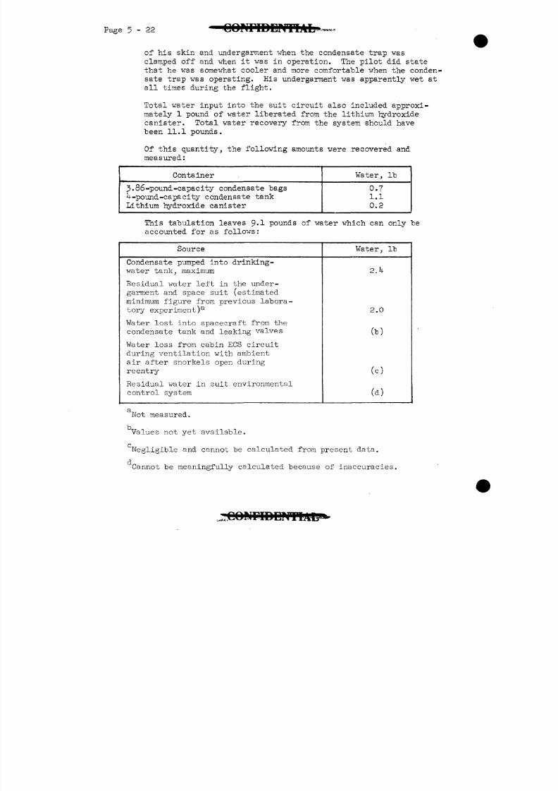
8/7/2019 Post Launch Memorandum Report for Mercury-Atlas No. 9(MA-9). Part 1 Mission Analysis
http://slidepdf.com/reader/full/post-launch-memorandum-report-for-mercury-atlas-no-9ma-9-part-1-mission 90/344
Page 5-22
of his skin and undergarment when the condensate trap wasclamped off and when it was in operation. The pilot did statethat he was somewhat cooler and more comfortable when the conden-sate trap was operating. His undergarment was apparently wet atall times during the flight.
Total water input into the suit circuit also included approxi-mately 1 pound of water liberated from the lithium hydroxidecanister. Total water recovery from the system should havebeen 11.1 pounds.
Of this quantity, the following amounts were recovered andmeasured:
Container
3. 86 -pound -capacity condensate bagsU-pound-capacity condensate tank
Lithium hydroxide canister
Water, Ib
0.71.1
0.2
This tabulation leaves 9-1 pounds of water which can only beaccounted for as follows:
Source Water, Ib
Condensate pumped into drinking-water tank, maximum
Residual water left in the under-
garment and space suit (estimated
minimum figure from previous labora-
tory experiment)3
Water lost into spacecraft from the
condensate tank and leaking valves
Water loss from cabin ECS circuit
during ventilation with ambient
air after snorkels open during
reentry
Residual water in suit environmental
control system
2.0
(b)
(c)
(d)
Not measured.
Values not yet available.
d
'Negligible and cannot be calculated from present data.
Cannot be meaningfully calculated because of inaccuracies.
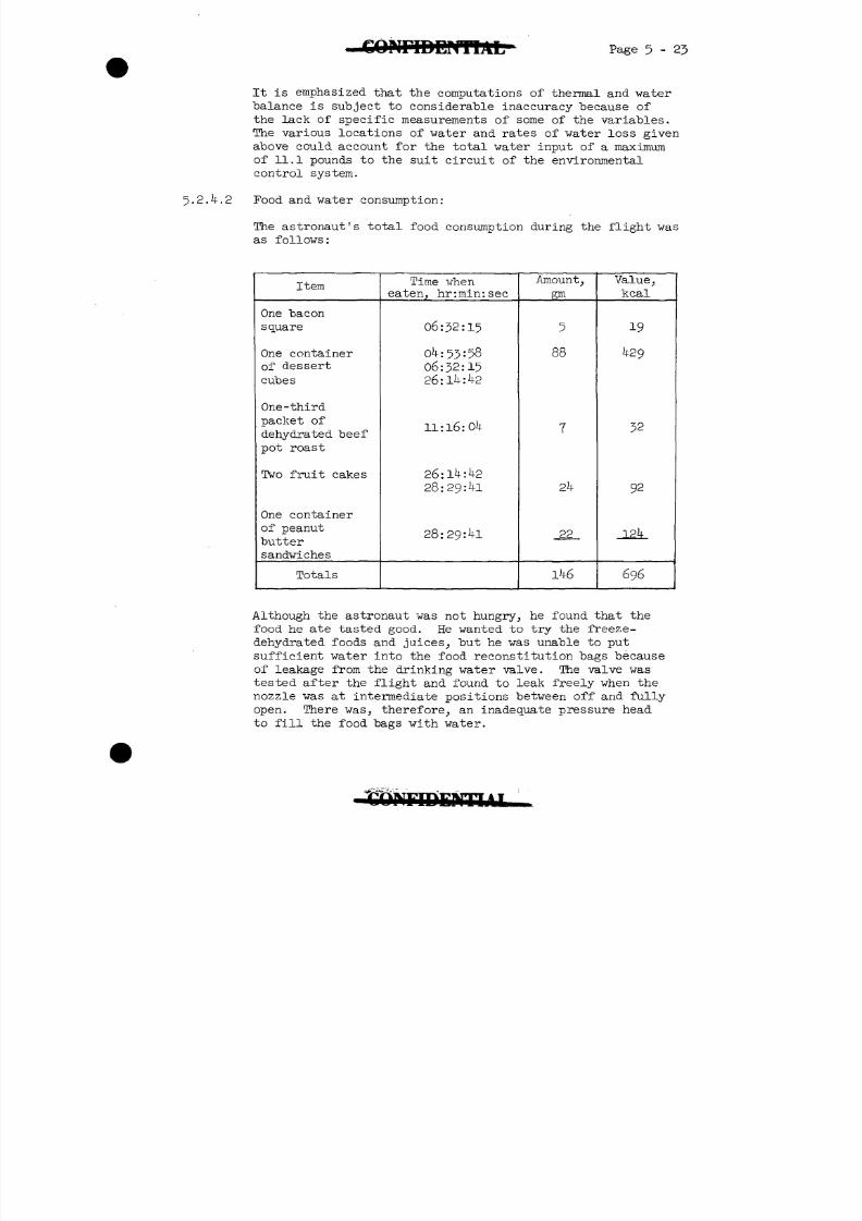
8/7/2019 Post Launch Memorandum Report for Mercury-Atlas No. 9(MA-9). Part 1 Mission Analysis
http://slidepdf.com/reader/full/post-launch-memorandum-report-for-mercury-atlas-no-9ma-9-part-1-mission 91/344
Page 5-2J
It is emphasized that the computations of thermal and vaterbalance is subject to considerable inaccuracy because ofthe lack of specific measurements of some of the variables.The various locations of water and rates of vater loss givenabove could account for the total water input of a maximum
of 11.1 pounds to the suit circuit of the environmentalcontrol system.
5.2.4.2 Food and water consumption:
The astronaut's total food consumption during the flight wasas follows:
Item
One baconsquare
One containerof dessert
cubes
One -thirdpacket ofdehydrated beefpot roast
Two fruit cakes
One containerof peanutbuttersandwiches
Totals
Time wheneaten, hr:min:sec
06:32:15
0 :53:58
06:32:1526:1 : 2
11: 16: 04
26:14:4228:29:41
28:29:41
Amount,gm
5
88
1
2k
_22_
146
Value,kcal
19
429
32
92
124
696
Although the astronaut was not hungry, he found that the
food he ate tasted good. He wanted to try the freeze-dehydrated foods and juices, but he was unable to put
sufficient water into the food reconstitution bags becauseof leakage from the drinking water valve. The valve wastested after the flight and found to leak freely when thenozzle was at intermediate positions between off and fullyopen. There was, therefore, an inadequate pressure headto fill the food bags with water.
8/7/2019 Post Launch Memorandum Report for Mercury-Atlas No. 9(MA-9). Part 1 Mission Analysis
http://slidepdf.com/reader/full/post-launch-memorandum-report-for-mercury-atlas-no-9ma-9-part-1-mission 92/344
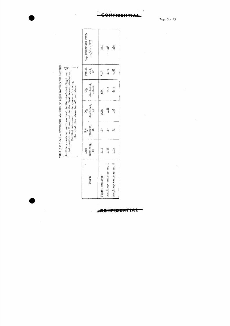
8/7/2019 Post Launch Memorandum Report for Mercury-Atlas No. 9(MA-9). Part 1 Mission Analysis
http://slidepdf.com/reader/full/post-launch-memorandum-report-for-mercury-atlas-no-9ma-9-part-1-mission 93/344
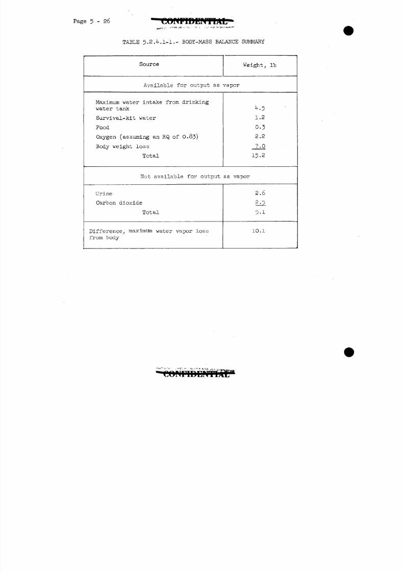
8/7/2019 Post Launch Memorandum Report for Mercury-Atlas No. 9(MA-9). Part 1 Mission Analysis
http://slidepdf.com/reader/full/post-launch-memorandum-report-for-mercury-atlas-no-9ma-9-part-1-mission 94/344
Page 5-26
TABLE 5.2A.1-1.- BODY-MASS BALANCE SUMMARY
Source Weight, Ib
Available for output as vapor
Maximum water intake from drinking
water tank
Survival-kit water
Food
Oxygen (assuming an RQ of 0.8j)
Body weight loss
Total
^•5
1.2
0.3
2.2
7-015-2
Not available for output as vapor
Urine
Carbon dioxide
Total
Difference, maxim-urn water vapor loss
from body
2.6
2.5
5 - 1
10.1
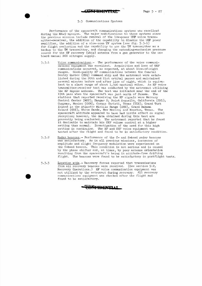
8/7/2019 Post Launch Memorandum Report for Mercury-Atlas No. 9(MA-9). Part 1 Mission Analysis
http://slidepdf.com/reader/full/post-launch-memorandum-report-for-mercury-atlas-no-9ma-9-part-1-mission 95/344
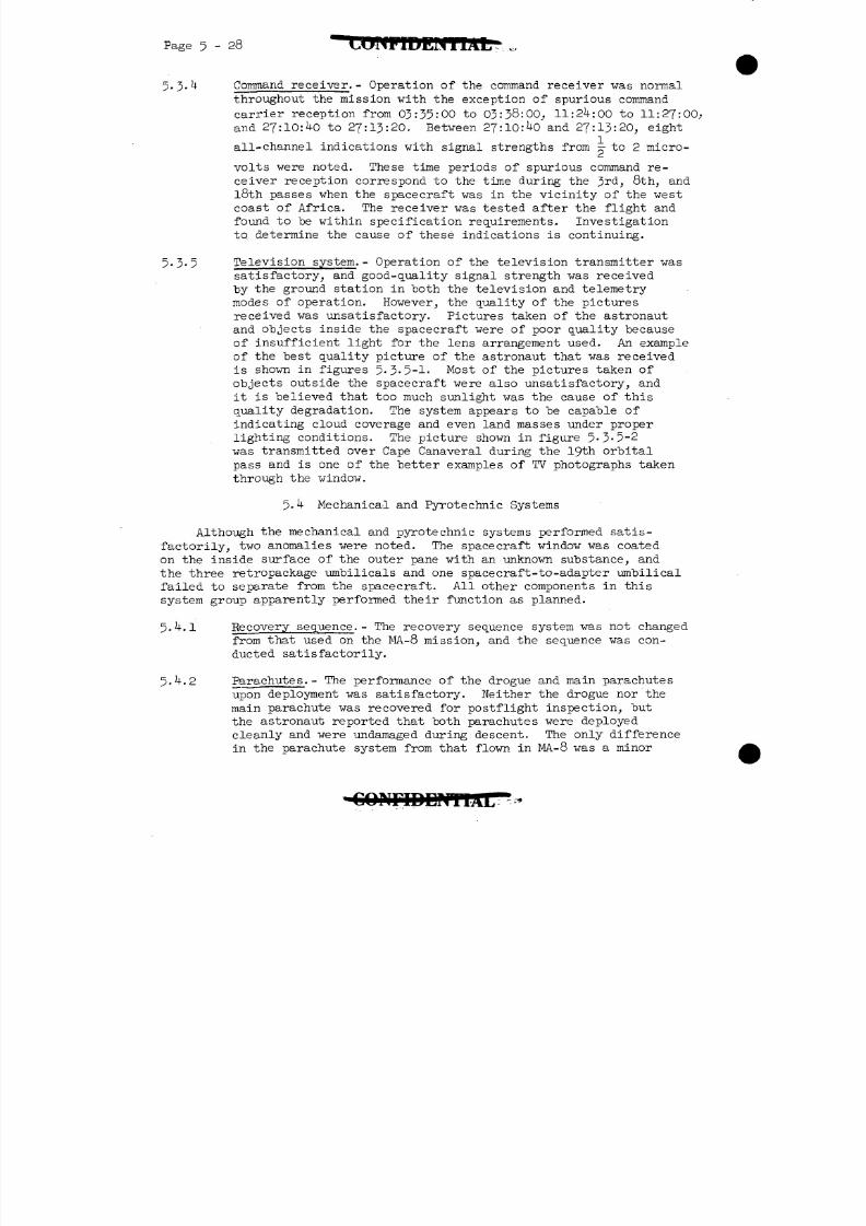
8/7/2019 Post Launch Memorandum Report for Mercury-Atlas No. 9(MA-9). Part 1 Mission Analysis
http://slidepdf.com/reader/full/post-launch-memorandum-report-for-mercury-atlas-no-9ma-9-part-1-mission 96/344
8/7/2019 Post Launch Memorandum Report for Mercury-Atlas No. 9(MA-9). Part 1 Mission Analysis
http://slidepdf.com/reader/full/post-launch-memorandum-report-for-mercury-atlas-no-9ma-9-part-1-mission 97/344
8/7/2019 Post Launch Memorandum Report for Mercury-Atlas No. 9(MA-9). Part 1 Mission Analysis
http://slidepdf.com/reader/full/post-launch-memorandum-report-for-mercury-atlas-no-9ma-9-part-1-mission 98/344
5. .5 Spacecraft window. - The astronaut reported that the spacecraftwindow was coated with some type of substance that caused the
window to have a frosted appearance under oblique lighting con-ditions. This coating was on the inside surface of the outerpane. A postflight analysis of the surface failed to show any-
thing that could cause this coating and the investigation iscontinuing.
5-^.6 Landing-shock attenuation system.- The MA-9 landing-shock attenu-ation system differed from the MA-8 configuration in that thepressure tank of the landing-bag actuation system was altered inshape and moved to the opposite side of the spacecraft to make room
for the hydrogen' peroxide fuel tank that was added to the RCS, andthe check valve on the ground checkout port was, deleted.
5-^.6.1 landing bag.- The landing bag was deployed at a pressure altitudeof 9,500 feet, and the system performed normally, as evidenced
by the astronaut's statements and from postflight examination.The postflight examination of the bag revealed some small tears
and rips, but they were of a minor nature. The straps and cableswere not damaged beyond that normally expected.
5-^.6.2 Ablation shield and main pressure bulkhead. - The ablation shieldappeared to be intact, and only minor circumferential cracks were
noted. The fiber glass protective shield had been scarred by theheat-shield lugs, indicating-that minor recontact, less than inprevious flights, haS occurred. The main pressure bulkhead didnot exhibit any visible damage. A more detailed discussion ofheat-shield performance is contained in section 5-7-
5.^.7 Flotation. - Reports and photographs from the recovery forcesand the astronaut indicate that the spacecraft righted itselfquickly and floated at the proper attitude once the parachuteshad been jettisoned.
5-5 Electrical and Sequential Systems
5.5.1 Electrical system.- The major modifications to the electricalsystem of the MA-9 spacecraft since the previous mission include
the replacement of the two 1,500 watt-hour standby batteries
with two 3 000 watt-hour batteries to increase the availableelectrical energy, the -replacement of the main inverters with
more efficient units which also had improved starting and coolingcharacteristics, the addition of a standby-inverter automatic tonegenerator to indicate automatic switching of the inverter to eithera-c bus, the addition of a switch to allow repowering of certainbuses after landing to permit postlanding recordings of blood-pressure and EGG readings, and the addition of an on-off switchin the flashing recovery light circuit.
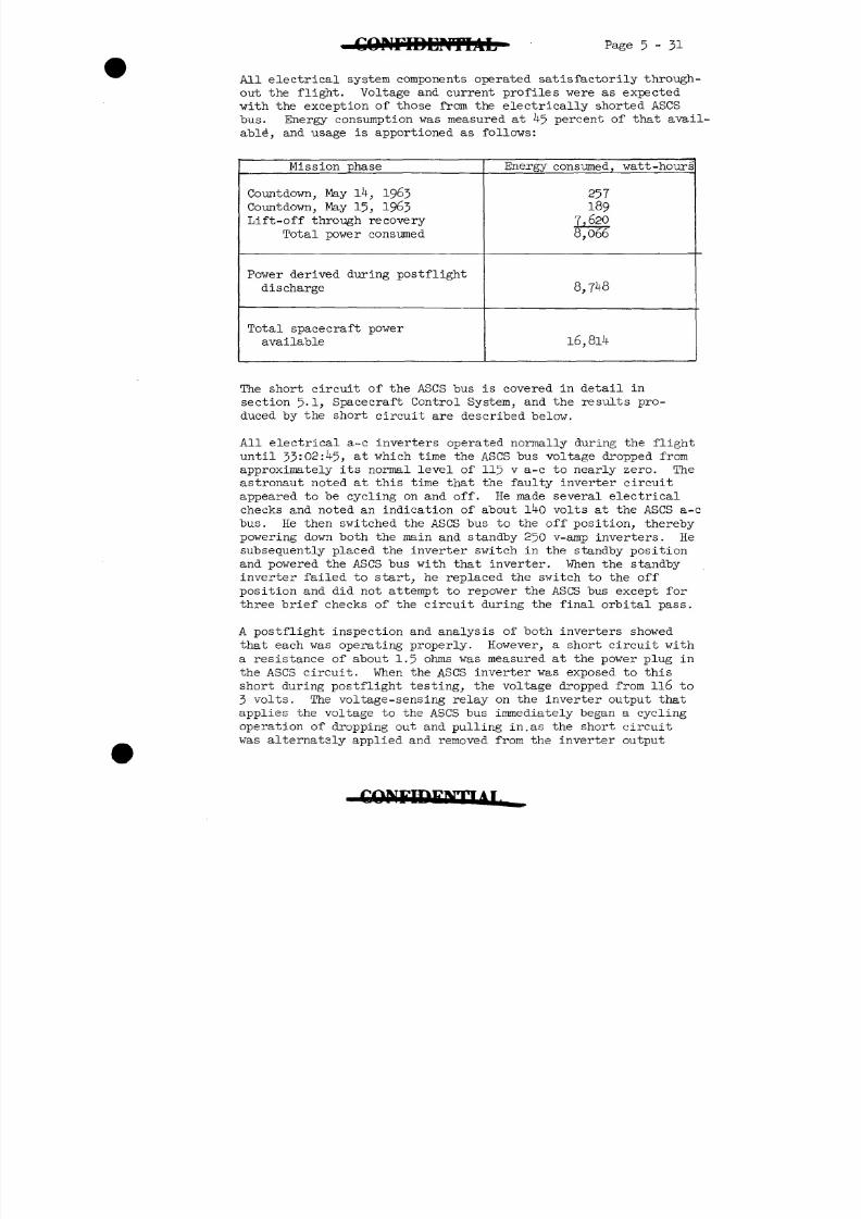
8/7/2019 Post Launch Memorandum Report for Mercury-Atlas No. 9(MA-9). Part 1 Mission Analysis
http://slidepdf.com/reader/full/post-launch-memorandum-report-for-mercury-atlas-no-9ma-9-part-1-mission 99/344
8/7/2019 Post Launch Memorandum Report for Mercury-Atlas No. 9(MA-9). Part 1 Mission Analysis
http://slidepdf.com/reader/full/post-launch-memorandum-report-for-mercury-atlas-no-9ma-9-part-1-mission 100/344
5 32 C O N F I D E N T I A L *
circuit. The large inductance associated with the outputimpedance of the inverter, along with the high rate ofcurrent change, resulted in large 600-volt spikes thatshorted the parallel diode (peak inverse voltage rating of300 volts) across the voltage sensing relay. With this diode
shorted, the relay stabilized in its deenergized state andcaused the standby inverter automatically to begin powering theshorted bus at 3 volts. The standby inverter warning light came
on at this time. During this test, the standby inverter wouldnot come up to full power because of the short circuit whichwas present at the power plug. Because this circuit failurecould be easily duplicated in the laboratory following theflight, it is believed a short circuit which prevented theirproper operation could have existed in flight and that no
malfunction of the inverters was present at any time duringthe flight. Additional laboratory tests show that the 1^0-volta-c meter reading reported by the astronaut resulted from
operation of the inverter under the unusual remaining load inthe circuit, which consisted of a 100,000-ohm resistor inparallel with a diode other than the one which was shorted.
5 - 5 - 2 Sequential system.- The major modifications to the sequentialsystem of the MA.-9 spacecraft include rewiring of the pilot'sabort circuitry to prevent inadvertent ignition of the tower-jettison rocket motor, rewiring of the retrorocket arm switchto provide the capability of disarming both the main and
isolated retrorocket squibs with automatic bypass at retro-grade signal, rewiring of the."fire-retro" green telelite tomake it dependent on the ignition of all three retrorockets,
and paralleling the no. 1 and no. 2 main parachute armingcircuits to increase reliability in arming the 21,000 ft drogue
parachute barostats.
The sequential system operated satisfactorily throughout the
mission, except for the premature 0.05g signal from theamplifier-calibrator, which is discussed in section 5-1- Thissignal caused the sequential system to remove power from theattitude gyros, the automatic retrosequence circuitry, theautomatic retropackage jettison circuitry, and the retrorockettelelites. Since these functions were latched out,' the pilotwas forced to use the emergency retrofire circuitry and to
jettison the retropackage manually.
Since the antenna canister was not recovered, the failure ofthe balloon deployment mechanism cannot be explained. Onboardtelemetry verifies that the squib firing relay used in deployingthe balloon was properly actuated. A more detailed explanationof this failure can be found in section 5-8
8/7/2019 Post Launch Memorandum Report for Mercury-Atlas No. 9(MA-9). Part 1 Mission Analysis
http://slidepdf.com/reader/full/post-launch-memorandum-report-for-mercury-atlas-no-9ma-9-part-1-mission 101/344
T'* Page 5-33
5.6 Instrumentation System
The instrumentation system monitors certain parameters relating to
specific equipment in the spacecraft, and, in general, the data are either
displayed to the astronaut or transmitted to the ground, or "both. Thedata transmitted are also recorded on the onboard tape recorder along with
additional data vhich are neither displayed nor transmitted.
5.6.1 System description.- The major changes made to the MA-9 instru-
mentation system include deleting the high frequency telemetry
system and the low-level temperature survey; adding switches to
allow the astronaut to select continuous, off, or ground command
for the telemetry transmitter and continuous, off, or program
for the onboard tape recorder; adding a switch to allow the
astronaut to remove power from the R- and Z-calibration relays
in the event the programer failed to perform this function;7
changing the speed of the onboard tape recorder from ITTinches
per second (ips) to T? ips to increase recording time; and adding
a new type programer which was to perform the following functions:
1. One minute of "on" time of the onboard tape recorder
every 10 minutes of elapsed time, with 15 seconds each of Z- and
R-calibrations during the last 30 seconds of the sixth cycle.
2. Six minutes of "on" time of the telemetry transmitter
together with 15 seconds each of R- and Z-calibrations after a
telemetry "on" command from the ground has been received.
3. Six minutes of "on" time of the C-band beacon together
with 15 seconds each of R- and Z-calibrations after a C-band
beacon "on" command from the ground has been received.
U. Six minutes of "on" time of the S-band beacon together
with 15 seconds each of R- and Z-calibrations after an S-band
beacon "on" command from the ground has been received.
In addition, the astronaut observer camera was replaced with a
l6-mm movie camera, which is shown in figure 5-6.1-1. The
l6-mm camera was a magazine loaded unit which was internally
powered by fourteen R-^-01 mercury cells. The camera could be
hand held by the pilot, mounted on the instrument panel to
photograph the pilot, or mounted at the window to photograph
objects outside the spacecraft. Three magazines of film were
provided. Two magazines were each loaded with approximately
120 feet of Eastman Ecktachrome film and they were to be used
for pilot observer, general, and reentry photography. The
8/7/2019 Post Launch Memorandum Report for Mercury-Atlas No. 9(MA-9). Part 1 Mission Analysis
http://slidepdf.com/reader/full/post-launch-memorandum-report-for-mercury-atlas-no-9ma-9-part-1-mission 102/344
8/7/2019 Post Launch Memorandum Report for Mercury-Atlas No. 9(MA-9). Part 1 Mission Analysis
http://slidepdf.com/reader/full/post-launch-memorandum-report-for-mercury-atlas-no-9ma-9-part-1-mission 103/344
1DENTIAL Page 5
when the astronaut was desuited aboard the recovery ship. Apostflight check of the harness disclosed a failed solder jointfor one of the wires to the side impedance pneumograph electrode.
Initial playback of the onboard tape indicated that the tape
recorder failed to operate in the program mode after 12:18:19.Recorder operation in the continuous and vox-record modes wasnormal throughout the mission. A postflight test of the pro-gramer indicated that the "A" section, which controls theprogram mode of recording, was completely inoperative. Visualinspection of the programer revealed that the "A" section wasinoperative because the mechanical timer was jammed. Thisjamming was caused by a misalined gear, which resulted from abroken gear shaft. The misalined gear is shown in figure 5-6-2-1.
At retrofire, the indicated carbon dioxide partial pressuredecreased rapidly from 3-0 mm Hg to zero. Postflight testing
'revealed a J-percent calibration shift which would not accountfor the inflight occurrence. However, methods have been foundfor. duplicating the sudden drop in PCCU, but these findings as
yet have not been correlated with realistic conditions- whichcould exist in the spacecraft. Investigations to determine thecause of this problem are continuing.
Immediately after retrofire, the indicated temperature of the150 v-amp inverter decreased from 120° F to 86° F in 35 seconds.The indicated temperature then increased slowly, followed bya slow decrease just prior to drogue parachute deployment.About 30 seconds after drogue deployment, the indicated tempera-
ture increased rapidly to 120° F. The temperature of the250 v-amp standby inverter also increased momentarily at thistime by about 6° F. The indicated readings are considered tohave been valid, since the sensors involved were found to beintact and operating normally. Although the possibility existsthat free water in the cabin at retrofire could have beendeposited on or near these sensors, thereby reducing the localtemperature suddenly, this thesis cannot be confirmed and furtherinvestigations are presently in progress.
At 3^-:09:24, there was dropout in the voltage control oscillator(VCO) outputs for the balloon experiment and for the roll,pitch, and yaw stick positions. This dropout lasted until3 :12:51, at which time the stick position outputs returned tonormal. Postflight testing on the stick position VCO's revealed,however, that they were functioning normally. The balloon ex-periment VCO could not be tested because it was in the antennacanister, which was not recovered at landing. Because all of theassociated spacecraft components, except the retropackage andthe antenna canister, which were not recovered, functionednormally during postflight tests, no explanation can be foundfor the dropout of these signals.
• C O N F I D E N T I A L
8/7/2019 Post Launch Memorandum Report for Mercury-Atlas No. 9(MA-9). Part 1 Mission Analysis
http://slidepdf.com/reader/full/post-launch-memorandum-report-for-mercury-atlas-no-9ma-9-part-1-mission 104/344
8/7/2019 Post Launch Memorandum Report for Mercury-Atlas No. 9(MA-9). Part 1 Mission Analysis
http://slidepdf.com/reader/full/post-launch-memorandum-report-for-mercury-atlas-no-9ma-9-part-1-mission 105/344
INTIAL ' Page 5 - 37
The measured weight loss of the heat shield was 15-3^ pounds,
which is comparable to that which was measured following
previous orbital missions.
5-7-2 Afterbody. - No temperature measurements were made on the
conical and cylindrical sections of the spacecraft. Postf lightexamination of the shingles revealed no areas where adverse
heating occurred.
5-7-3 Paint patch evaluation.- Three individual types of white
paint coatings were applied to a Rene ' 4l shingle on the
conical section, as shown in figure 3 • 1-1 • Each patch was
6 inches square and approximately h mils in thickness. The
three types of pigments were titanium dioxide, zinc oxide,
and zirconium oxide. The coatings were applied with a thermal-
drying binder and cured with a special application to obtain
better adhesion and color characteristics . Previous attempts
to obtain similar results were not successful, probably becausean air-drying binder was used. Postflight inspection revealed
that all three coatings were discolored. The titanium dioxide
and zinc oxide coatings remained bonded to the shingle; however,
the zirconium oxide coating exhibited extensive peeling.
(See fig. 5-7-3-1- ) The paint patches did not experience
erosion, as was evident on previous flights. Further laboratory
investigations are necessary before a conclusion can be reached
regarding discoloration and flaking.
C O N F I D E N T I A L
8/7/2019 Post Launch Memorandum Report for Mercury-Atlas No. 9(MA-9). Part 1 Mission Analysis
http://slidepdf.com/reader/full/post-launch-memorandum-report-for-mercury-atlas-no-9ma-9-part-1-mission 106/344
Page 5 ~
5.8 Scientific Experiments
A number of experiments and scientific observations were plannedfor the MA-9mission. These experiments were concerned with atmosphericdrag measurements, visual acquisition and tracking effectiveness, various
photographic exercises, cosmic radiation measurements, and general pilotobservations. The results of this experimental effort, which utilizedequipment or materials not normally associated with the basic spacecraftoperation, are briefly summarized in the following paragraphs.
5-8.1 Dim-light photography. • - The dim-light photography experimentwas intended to provide photographic data on two phenomena,which are best observed from outside the earth's atmosphere.These phenomena are the so-called zodiacal light and thenight airglow. Photographs of the zodiacal light would helpto determine its exact origin, geometric distribution, andrelationship to solar radiation and flare activity. Data on
the airglow would provide further information on the solar-energy conversion processes occurring in the upper atmosphere.
Observations of the zodiacal light are partially obscured or
become impossible when viewed through the atmosphere because
of absorption and scattering. For example, measurements of
the brightness of the zodiacal light within 30° °f ^he sun
have not been possible because of the interference of twi-
light.
Space flights provide an excellent opportunity to view the
bright night airglow band in profile. Some data were col-
lected during the MA.-7 mission on the altitude and bright-ness of the airglow layer above the earth by observing and
timing the passage of a star through it. The photographs
planned for the MA.-9 mission were intended to provide\ further
information on the brightness, structure, and altitude of this
airglow band.
The camera used in this experiemnt was a semi-automatic
35-mm hand-held instrument fitted with a fast lens which is
shown in figure 5-8.1-1. The square aperture of the shutter
limited the speed of the lens to an equivalent of f/0.95- Its
controls were simplified so that operation by the pilot in a
pressure suit would be facilitated. Exposures were manually
timed by depressing a trip button for the duration of the
exposure. For aiming purposes, three small supports or
"feet," capped with silicone rubber, were provided to assist
in maintining the camera in a fixed position relative to the
spacecraft window. The camera field of view was 35° total angle,
with little vignetting over the field. Ansco H 529 emulsion
film, having a film speed of 200, was used for the experiment.
8/7/2019 Post Launch Memorandum Report for Mercury-Atlas No. 9(MA-9). Part 1 Mission Analysis
http://slidepdf.com/reader/full/post-launch-memorandum-report-for-mercury-atlas-no-9ma-9-part-1-mission 107/344
Page 5-39
With the spacecraft in retroattitude, the camera was to be
held against the window so that the nominal position of the
earth's horizon would "be 5° below the center of the frame.
Dim-light photography was performed on the night side of the
l6th orbital pass with all cabin lights out. Just prior tosunset,, the spacecraft was oriented into the plane of the
ecliptic and flown on automatic attitude control throughout
the zodical- light photography period. This sequence was
started just after sunset and several photographs, varying
in exposure duration from one to 30 seconds, were taken.
The initiation and conclusion of all exposures were planned
to be voice-marked on the onboard tape to time the duration
of each exposure. A total of 17 exposures were made of the
zodiacal light during this mission.
Upon completion of the zodiacal-light photographs, the gyro
switch was placed in the slave position and the spacecraftwas slowly reoriented to orbit attitude. Throughout the
remainder of the night period, five series, each containing
a 2-minute, a JO-second, and a 10-second exposure, were made
of the horizon and airglow layer. A total of 15 exposures
were made in this series. Two 30-second and two 1-second
exposures were made of the western horizon when the space-
craft was passing over the terminator at sunrise.
Since much of the analysis depends on conducting microdensitom-
etry of the film, it is premature at this time to present con-
clusions for this experiment. A general summary of the photo-
graphs obtained, however, is available. In the zodiacal-lightsequence, the first two frames showed exposures of dim light,
and all exposures contain stars. The photographs, however,
are generally underexposed and will be of limited value for
analysis. Because of the strong gradient in the zodiacal-
light intensity near the sun, either a small delay in begin-
ning the photography sequence or improper camera aiming would
result in underexposure of the film. A delay of 2 minutes in
beginning the exposures, an 8° e'rror in aiming the camera, or
a combination of the two could decrease the light intensity by
a factor of 10. Because of the known variance in spacecraft
attitude when in the automatic control mode, some attitude
misalinement would naturally be expected. The astronaut also
stated that the message he transmitted over Zanzibar on the
16th orbital pass delayed him somewhat in preparing for the
dim-light experiment, and preliminary data indicate that the
sequence was not begun until 1 minute 0 seconds after sunset.
However, the star patterns appearing in the zodiacal-light
photographs should provide a reference from which camera
sighting can be accurately reconstructed.
8/7/2019 Post Launch Memorandum Report for Mercury-Atlas No. 9(MA-9). Part 1 Mission Analysis
http://slidepdf.com/reader/full/post-launch-memorandum-report-for-mercury-atlas-no-9ma-9-part-1-mission 108/344
P a g e 5 - 4o C O N F I D E N T I A L ^>
The exposures in each of the five series of -airglow photographs
were all of usable quality. Figure 5-8.1-2 is a representative
photograph of this series, shoving the thin "band of the airglow
layer just above the horizon. Some of the 2-minute exposures
are slightly blurred by rates in roll and pitch, but most of the
10-second exposures are quite sharp, vith the airglow layerlocated near the base of the photograph. Preliminary measure-
ments of the angular thickness of the airglow layer indicate
that the layer is about 5-5°in thickness. The four exposures
made at sunrise were all overexposed.
5.8.2 Ground-light experiment.- The ground-light experiment was
designed to evaluate the operational problems associated with
visual acquisition from space of earth-based lights and to
compare the observed brightness with predicted values. This
type of information is necessary to determine the feasibility
of using ground lights as navigation fixes during future space
missions.
The light assembly used for this experiment was a pulsed xenon-
arc type consisting of three sections of six lamps each as
shown in figure 5-8.2-1. The lamps were mounted in a shallow
open-top box above a polished reflective surface. The circuit
was operated by a 50-cycle three-phase electrical power supply,
and the lamps in each section flashed 50 times a second with
an input of 27-5 watt-seconds per flash per lamp. Based on a
if-0-kilowatt nominal input to the lamp power supply, the com-
puted average intensity of the light was estimated to be
approximately 120,000 candles in the hemisphere above the light.
The light was located in the Republic of South Africa, 6 miles
east of the town Bloemfontein, which is at 29°06' S latitude,
26cl8' E longitude, and k,k^>k feet in elevation. With the
spacecraft at an attitude of - 0° in pitch and 0° in roll and
yaw, the light would first come into view at about 8:23:00 and
a slant range of 320 nautical miles with an estimated inten-
sity of about a 2.8-magnitude star.
The lamp was turned on at 8:21:56 and turned off at 8:25:06.
The weather was reported on the ground as having been completely
clear at that time. The light was seen by the astronaut prior
to moonrise during his pass over this area. By moving away from
and back to a fixed attitude, the pilot was readily able to
reacquire the light. The pilot estimated that when the light
came into view, it was equal to about a third-magnitude star.
It was in sight for 30 to ^0 seconds before it faded out at
which time the intensity of the light was between Uth and 5th
magnitude in brightness. The experiment produced approximately
the same sighting results as predicted.
CONFIDENTS
8/7/2019 Post Launch Memorandum Report for Mercury-Atlas No. 9(MA-9). Part 1 Mission Analysis
http://slidepdf.com/reader/full/post-launch-memorandum-report-for-mercury-atlas-no-9ma-9-part-1-mission 109/344
• J C O M l D C P f T I A L ^ge 5 - M
The astronaut considered the light of sufficient brightness
. to be used as a navigation landmark if adequate sighting
information were to be made available. He stated, however,
that the distinctive U-shaped light pattern of the town of
Bloemfontein was a very helpful factor in identifying the
light; the light from the town was about as visible as thetest light and both faded from view at the same time. He
stated that a flashing light would have been much more dis-
tinctive, and he "believed that a pattern of flashing lights
would have been even more distinguishable.
The pilot's observations of the ground light also show that,
for any use of a lighted landmark as a navigation aid, the
rapid passage over the ground (involving angular tracking
rates of as high as l80°/minute) requires that instrument
readings be made very conveniently and rapidly. An attempt
to use the extinction photometer for this experiment was un-
successful.
5.8.3 Radiation studies.- Instrumentation was placed aboard the
spacecraft to measure and record the amount of radiation
encountered on the flight. These measurements are needed to
verify theoretical flux estimates and shielding calculations.
and to ascertain the dose received by the astronaut. Two
major types of radiation are present within the Mercury
orbital altitude range: Protons which are naturally present
in the lower Van Allen belt and electrons which were produced
by decaying fission nuclei from the atomic explosion of July
1962. These radiations are most pronounced for the space-
craft's orbit in an area over the South Atlantic between thecoasts of South America and Africa because of an anomaly in
the earth's magnetic field at that location.
Two Geiger counters were mounted on the retropackage (see
fig. 5-8.3-1) to measure the electron flux incident on the
vehicle. One counter surveyed a hemispherical area about an
axis alined along the 195° yaw and -lit-00pitch attitudes,
relative to the spacecraft axes. The other counter was
collimated to view a solid angle of approximately 0.8 steradian
along the spacecraft's Z-axis. The latter counter, coupled
with vehicle attitude information, was included to provide
Information on the directionality of the electron flux. Thetubes in both counters had a mass concentration in the wall
i~\
of 90 ilO mg/cm and were filled with a low-pressure, neon-argon,
and halogen mixture. The uncollimated tube had, in addition,
a 1-mm tungsten shield to allow passage of primarily high-energy
electrons. Although Geiger tubes are sensitive to protons, the
8/7/2019 Post Launch Memorandum Report for Mercury-Atlas No. 9(MA-9). Part 1 Mission Analysis
http://slidepdf.com/reader/full/post-launch-memorandum-report-for-mercury-atlas-no-9ma-9-part-1-mission 110/344
P a g e 5 - te C O N F I D E N T I A L
count rates recorded were expected to result primarily inelectrons, since the electron flux is several orders of magni-tude higher than proton flux in the geographical region inquestion. A high-voltage power supply maintained an operatingplateau of approximately 550 volts. Power to the tubes was
controlled by a toggle switch on the main instrument panel.The voltage output, proportional to the count rate, was multi-plexed and stored on the onboard magnetic tape.
Radiation inside the spacecraft was monitored by a self-indicating ionization chamber placed on the interior of theegress hatch, which represents a region of minimum shielding.The ion chamber, combined with outside flux measurements,was intended to yield information on the minimum shieldingcharacteristics of the spacecraft and permit an estimate ofthe dosage received by the astronaut. Electron-sensitive filmbadges were placed in the astronaut's helmet and on his under-
wear, in the vicinity of the chest and the right thigh, tomeasure the received dosage. A nuclear emulsion package wasmounted behind the instrument console to register the protondosage.
Since the data were recorded on the onboard tape, it was neces-sary to have the tape recorder on during periods of measurement.During passage through the magnetic anomaly for orbitalpasses 5, 7, and 8, the switch was turned to the "on" position,and the magnetic tape recorder turned to "continuous." Back-ground readings were obtained on the l6th, l8th, and 19th
orbital passes.
The ion chamber was placed on the hatch within 1 hour afterlift-off and remained there until it was stowed just priorto retrofire. A postflight reading of this sensor was obtainedon the ground.
For the other radiation monitors, no astronaut participationwas required. These items were recovered and are being analyzedby the U. S. Naval School of Aviation Medicine for evaluation.
Appreciable count rates from the Geiger tubes were obtained,as expected, on the 7th orbital pass. The spacecraft was in
ASCS orbit attitude during the pass through the anomaly andshould give information on the electron flux and directionsrelative to the spacecraft. However, at the time of thiswriting, considerable data reduction and interpretation remainto be accomplished before any quantitative statements can bemade on the electrons in this anomaly.
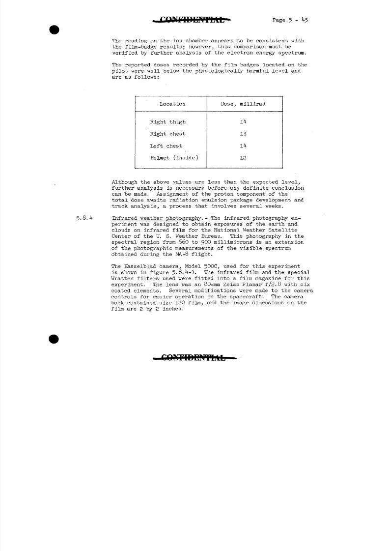
8/7/2019 Post Launch Memorandum Report for Mercury-Atlas No. 9(MA-9). Part 1 Mission Analysis
http://slidepdf.com/reader/full/post-launch-memorandum-report-for-mercury-atlas-no-9ma-9-part-1-mission 111/344
8/7/2019 Post Launch Memorandum Report for Mercury-Atlas No. 9(MA-9). Part 1 Mission Analysis
http://slidepdf.com/reader/full/post-launch-memorandum-report-for-mercury-atlas-no-9ma-9-part-1-mission 112/344
Page 5:- kk C O N F I D E N T I A L - *
The infrared spectrum from 660 to 900 millimicrons wavelength:was divided into three parts by inserting filters in the camera'so that sections of the image were photographed through each of-,
the three filters. Kodak Wratten gelatin filters measuring2-1/4 by 3/4 inches each were mounted in vertical strips in a '
thin metal holder, which was located in front of the film plane.The filters are listed in the following table. The lower boundaryof each spectral region is defined by the filter transmission andthe upper boundary is limited by the film sensitivity.
Wavelength,
660
730
810
millimicrons
to
to
to
900
900
900
Filter
W-70 and 1
W-88A
W-87C
and
.0 neutral density
0.9 neutral density
A neutral density filter was added to the W-70 and W-88A filtersections to obtain the same light attenuation through thesefilters as was obtained through the more opaque W-87C filter.The filters appear in the photographs in the order listed inthe table, with the W-70 filter section on the left, theW-88A in the center, and the W-87C on the right.
Kodak high-speed infrared film was used and coated on a regular
base support (0.005 inch thick). The film is sensitive throughthe visible region of the spectrum and in the infrared to approxi-mately 900 millimicrons, with the highest sensitivity in theregion from 770 to 84o millimicrons. The filters absorbed allthe light from the visible spectrum and transmitted to the filmonly the infrared wavelengths. The ASA daylight-exposure indexis 80 without filters. A shutter speed of 1/125-second and alens aperture setting of f/5.6 was used for these exposures.
A series of l6 infrared photographs were taken by the astro-naut over the southern part of the United States and the southernpart of Africa near the end of the 17th and beginning of the
l8th orbital passes, starting at an elapsed time of 26:38:00.Figure 5-8.4-2 is representative of the photographs obtainedfor this experiment. Geographic locations can be determinedaccurately from landmarks in the first ten pictures where cloudsdo not obscure the earth. These pictures showed that cloudscovered most of the Pacific coast of Worth America. Cloudiness,which was associated with a low-pressure area over Oklahoma,covered most of the lower Mississippi River Valley region and
8/7/2019 Post Launch Memorandum Report for Mercury-Atlas No. 9(MA-9). Part 1 Mission Analysis
http://slidepdf.com/reader/full/post-launch-memorandum-report-for-mercury-atlas-no-9ma-9-part-1-mission 113/344
8/7/2019 Post Launch Memorandum Report for Mercury-Atlas No. 9(MA-9). Part 1 Mission Analysis
http://slidepdf.com/reader/full/post-launch-memorandum-report-for-mercury-atlas-no-9ma-9-part-1-mission 114/344
P a g e 5 - k6 " CQNPIDEJmAL
space missions. Results from the experiment conducted during the
MA-9 flight were intended to extend the data previously obtained
during the MA-7 mission on the relative elevations of the earth's
limb as -photographed through blue and red filters. Past results
indicate that this variation in earth-limb height was dependent
upon the scattering angle of the incident sunlight. Therefore,a time-extended series of pictures embracing most of the daylight
period of an orbital pass was desired. It was also desired to
obtain a group of photographs taken over a brief time.period
in four quadrantal directions relative to that of the sun. Ac-
curately timed photographs of the earth horizon including the
setting moon were also requested to provide a reference for
measuring the altitude or elevation of the limb.
These photographs were made with the Hasselblad camera, pre-
viously described in section 5.8A. A lens setting of f/8 and
a shutter speed of 1/125 second was used. A filter sandwich
consisting of a no. 92 (red) Wratten filter central panel andtwo no. i)-7B(blue) filter side panels were mounted immediately
ahead of the film plane. A narrow, opaque bar extended through
the center of the red filter to hold the filter flat. Linagraph
Shellburst film was used for the experiment.
A planned series of photographs of the earth's horizon through-
out the daylight portion of an orbital pass was not performed
during the 21st orbital pass, as programed, because of the space-
craft control system malfunction. The quadrant photographs and
photographs of the moon-earth limb were taken as planned. A
total of 11 exposures were made, 8 quadrantal photographs (2 of
each quadrant) and 3 moon-set earth-limb photographs.
Because of an unforeseen difficulty in loading the modified
camera back and a consequent inadvertent exposure of the film
to light from a red safe-light, some background "light-struck"
damage was incurred by the film prior to flight.
Careful initial inspection of the film indicated that six of
the eight quadrantal exposures and two of the three moon-set
pictures are usable for quantitative study. The film includes
two good sets of step-wedge sensitometric exposures for cali-
bration, one before the flight and one after. Correction for
the inadvertent background can be made, at least where it isof moderate density.
Since these densitometric exposures were made with a calibrated
source, a radiance value for the observed limb can be eventually
obtained from the data. The MA-9 results in this regard, con-
stitute a significant advance beyond the photography of the
MA-T flight.
8/7/2019 Post Launch Memorandum Report for Mercury-Atlas No. 9(MA-9). Part 1 Mission Analysis
http://slidepdf.com/reader/full/post-launch-memorandum-report-for-mercury-atlas-no-9ma-9-part-1-mission 115/344

8/7/2019 Post Launch Memorandum Report for Mercury-Atlas No. 9(MA-9). Part 1 Mission Analysis
http://slidepdf.com/reader/full/post-launch-memorandum-report-for-mercury-atlas-no-9ma-9-part-1-mission 116/344
8/7/2019 Post Launch Memorandum Report for Mercury-Atlas No. 9(MA-9). Part 1 Mission Analysis
http://slidepdf.com/reader/full/post-launch-memorandum-report-for-mercury-atlas-no-9ma-9-part-1-mission 117/344
8/7/2019 Post Launch Memorandum Report for Mercury-Atlas No. 9(MA-9). Part 1 Mission Analysis
http://slidepdf.com/reader/full/post-launch-memorandum-report-for-mercury-atlas-no-9ma-9-part-1-mission 118/344
P a g e 5 - 50 GOMlDEMnAL
During the third night period, at 3 hours 25 minutes after
deployment and at a range calculated to "be betveen 9^ and1 ^
11 nautical miles, the light was rated as very veak and just
"barely discernible. This rating indicated again that thebeacon was not as bright as expected. The astronaut alsoestimated distances as well as brightness; and since therewere no distance cues other than those related to previousaircraft sightings, he consistently estimated distances thatwere too great.
The sightings were made with all spacecraft internal lightsturned off. An attempt to sight the beacon during the day-light period after the first night period, when the calculatedminimum range was less than 2 nautical miles, was unsuccessful.Although, at other times, stars were seen during the daytime,
none were seen during the daylight period in which the astro-naut was trying to acquire the light.
In general, it was found that the flash of the light made iteasily distinguishable from stars. The "beacon's intensityappeared to be adequate for acquisition up to distances ofabout 8 nautical miles at night.
5.8.7 Tethered balloon experiment.- A JO-inch-diameter mylar spherewas packaged in the antenna canister of the spacecraft and wasto be ejected, inflated, and tethered at the end of a 100-footnylon line for one orbital pass. However, the balloon failedto deploy and the experiment was not accomplished. This experi-ment was intended to provide further information about theatmospheric density through the altitude profile of the Mercuryspacecraft, which ranged from 8k to 1^6 nautical miles. Atmos-pheric density was to be computed by determining the drag ofthe balloon, as measured by the pull of the tether on a strain-gage balance located at the bottom of the balloon canister. Theequipment configuration for the experiment was nearly identicalto that included in the MA-7 spacecraft for a similar experimentexcept that the balloon was painted fluorescent orange and it
was constructed by laminating a T--mil-thick metalized plastic
sheet to a -mil-thick clear plastic -sheet. The l6-mm camera
(see fig. 5-6.1-1) was mounted in the spacecraft so that photo-
graphic coverage of the balloon's motions could be obtained.
8/7/2019 Post Launch Memorandum Report for Mercury-Atlas No. 9(MA-9). Part 1 Mission Analysis
http://slidepdf.com/reader/full/post-launch-memorandum-report-for-mercury-atlas-no-9ma-9-part-1-mission 119/344
8/7/2019 Post Launch Memorandum Report for Mercury-Atlas No. 9(MA-9). Part 1 Mission Analysis
http://slidepdf.com/reader/full/post-launch-memorandum-report-for-mercury-atlas-no-9ma-9-part-1-mission 120/344
Page 5-52
tend to fall in patterns that would "be easily discernible to
the pilot. Furthermore, since the spacecraft was drifting, theamount of light falling on the window should be varying con-tinuously, but the pilot stated that the lightness of the skyappeared uniform. Therefore, it appears unlikely that thisobservation can be accounted for by scattered light on -th e
window.
The best explanation for this brightening of the sky is theo
presence of a general 6300 A emission region above the space-o
craft. The height of the 6300 A dayglow is not know, but mayoccur in the F-region of the atmosphere which is at an altitudeof about 250 kilometers. Preliminary estimates indicate that
o
the visible emission of the 6300 A dayglow could increase thebrightness of the day sky about 3 times above the level of the
night sky. This hypothesis agrees reasonable well with the
pilot's estimate of the reduction in light intensity of starsvisible during daylight.
All of the astronauts have reported the presence of a so-calledhaze layer on the night side of an orbital pass. This termappears to be a misnomer, since the phenomenon probably involvesa region of concentrated airglow emission in the 100-kilometerregion of the atmosphere. The effect of weakening a star'sintensity as it passes through this region could be caused bya loss of visibility, with respect to the increased brightnessof the airglow foreground, as readily as if it were caused by
the presence of a haze or attenuating layer. Present evidence
supports the former explanation, since measurements of the heightof the layer agree with that of the night airglow layer.
The pilot also reported observing a brownish glow in an east-northeasterly direction above his orbital altitude at an elapsedtime between 17:25:00 and 17:30:00. At this time, the space-craft was just above the east coast of South America in thevicinity of Belem, Brazil. Thus, the phenomenon occurred inthe tropics not far from the geomagnetic equator. The glowappeared as a patch with an approximate angular size equal tothe spacecraft window, rather than a layer, and the observationseems to be similar to that reported over the Indian Ocean during
the MA-8 mission. Postflight calculations indicate that theo
phenomenon was caused by the integrated effect of a 6300 A
cloud of about 3,000 kilometers in horizontal extent. If thetypical vertical thickness is assumed to be about 50 kilometers,then the integrated intensity of the cloud seen edge-on would beabout 18,000 rayleighs, about the intensity required to give avisual impression of a light brownish nature.
8/7/2019 Post Launch Memorandum Report for Mercury-Atlas No. 9(MA-9). Part 1 Mission Analysis
http://slidepdf.com/reader/full/post-launch-memorandum-report-for-mercury-atlas-no-9ma-9-part-1-mission 121/344
Page 5-53
The pilot also reported that at about 20 seconds after sun-
set, a whitish arch extending some 15° or so above the horizon
appears above the sun. Two possible explanations of this arch
exist:
1. It could be the outer corona of the sun.
2. It might be associated with a concentration of dust
around the earth - a sort of terrestrial "zodiacal light."
Approximately 1 minute after sunset, the pilot detected the
zodiacal light. At this time, the spacecraft window was pro-
bably significantly illuminated by the bright remnants of the
orbital twilight. The ability of the pilot to detect the
zodiacal light above the window foreground suggests that it
must have been brighter than the orbital twilight. This is
as it should be at angular distances from the sun of 6° to
10°, which was probably the minimum observed distance. Thefact that the light was concentrated along the ecliptic
established it as truly "zodiacal light."
Thirty general purpose color photographs were taken on this
mission by using the 70-mm Hasselblad camera described in
section 5-8.4. The exposures were made without a filter on
ultraspeed Anscochrome (FPC 289) by using a lens setting of
f/l6 and a shutter speed of 1/250 second. Photographic cover-
age of portions of northern Africa, Arabia and the India-Burma-
China area was obtained. A number of very good exposures of the
Himalayas with excellent resolution were obtained. Figure 5-8.8-1
is an example of these photographs. Some photographs of thewestern Pacific and of the Indian Ocean areas were also taken.
In general, the quality and resolution of these photographs
were excellent, and the resolution of terrain features of
the best of the MA-9 photographs compare favorably to that
of the Viking infrared photographs. Interestingly enough,
however, no cultural features whatsoever can be seen on these
color photographs. Even the city of Calcutta, India, could not
be identified, although the quality of the photograph was ex-
cellent. A complete analysis of these photographs will require
a considerable amount of time; however, a preliminary analysis
indicates that this film-camera combination is capable of
yielding photographic information which could be useful for
geological, topographical, and meteorological purposes. All of
the photographs, even if slightly overexposed, contain some usable
information.
C O N F I D E N T I A L -
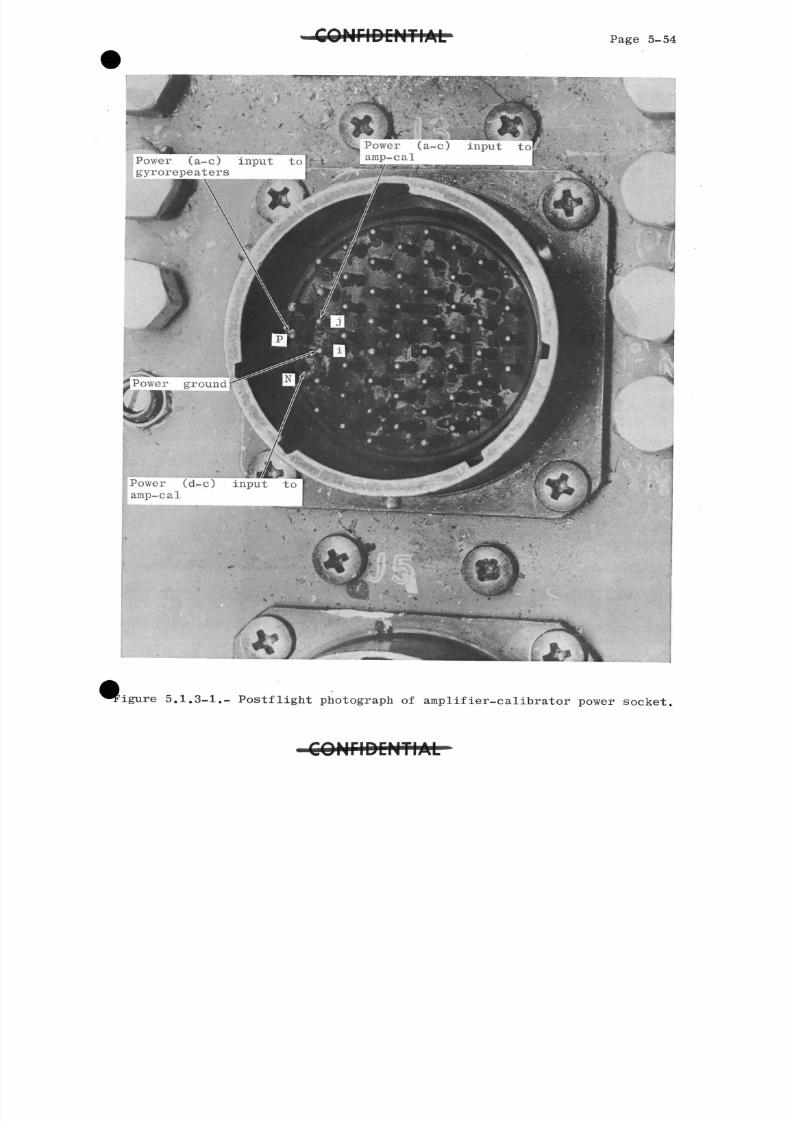
8/7/2019 Post Launch Memorandum Report for Mercury-Atlas No. 9(MA-9). Part 1 Mission Analysis
http://slidepdf.com/reader/full/post-launch-memorandum-report-for-mercury-atlas-no-9ma-9-part-1-mission 122/344
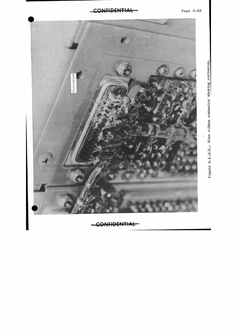
8/7/2019 Post Launch Memorandum Report for Mercury-Atlas No. 9(MA-9). Part 1 Mission Analysis
http://slidepdf.com/reader/full/post-launch-memorandum-report-for-mercury-atlas-no-9ma-9-part-1-mission 123/344
**f\.ft ir*i r\PkiTI A 1Page 5-55
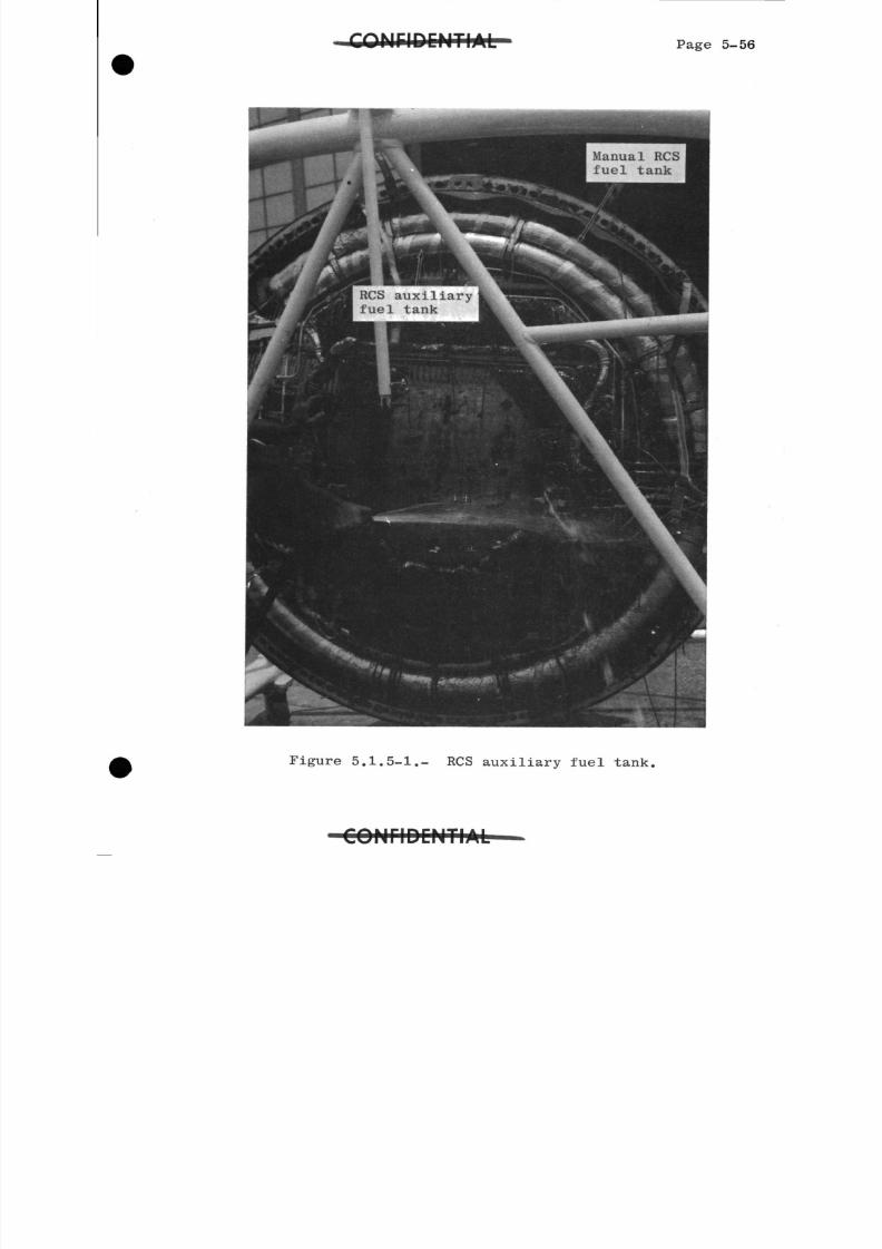
8/7/2019 Post Launch Memorandum Report for Mercury-Atlas No. 9(MA-9). Part 1 Mission Analysis
http://slidepdf.com/reader/full/post-launch-memorandum-report-for-mercury-atlas-no-9ma-9-part-1-mission 124/344
Page 5-56
Manual RCSfuel tank
RCS auxiliaryfuel tank
Figure 5.1.5-1.- RCS auxiliary fuel tank,
C O N f l D C H T I A L -
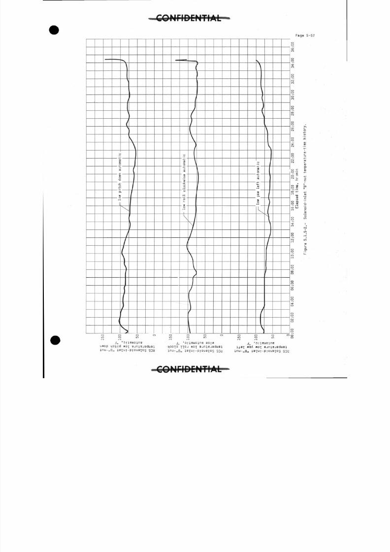
8/7/2019 Post Launch Memorandum Report for Mercury-Atlas No. 9(MA-9). Part 1 Mission Analysis
http://slidepdf.com/reader/full/post-launch-memorandum-report-for-mercury-atlas-no-9ma-9-part-1-mission 125/344
' C O N F I D E N T I A L
P a g e 5 - 5 7
S O W
C Q M r i D C M T I A L
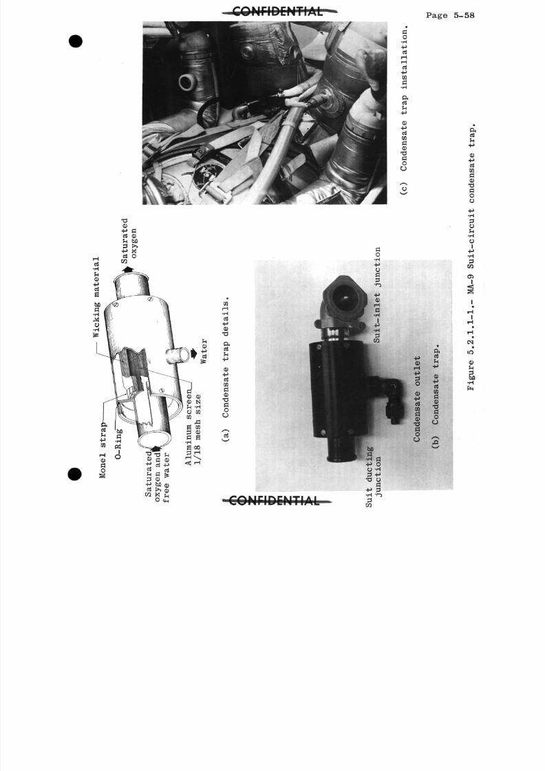
8/7/2019 Post Launch Memorandum Report for Mercury-Atlas No. 9(MA-9). Part 1 Mission Analysis
http://slidepdf.com/reader/full/post-launch-memorandum-report-for-mercury-atlas-no-9ma-9-part-1-mission 126/344
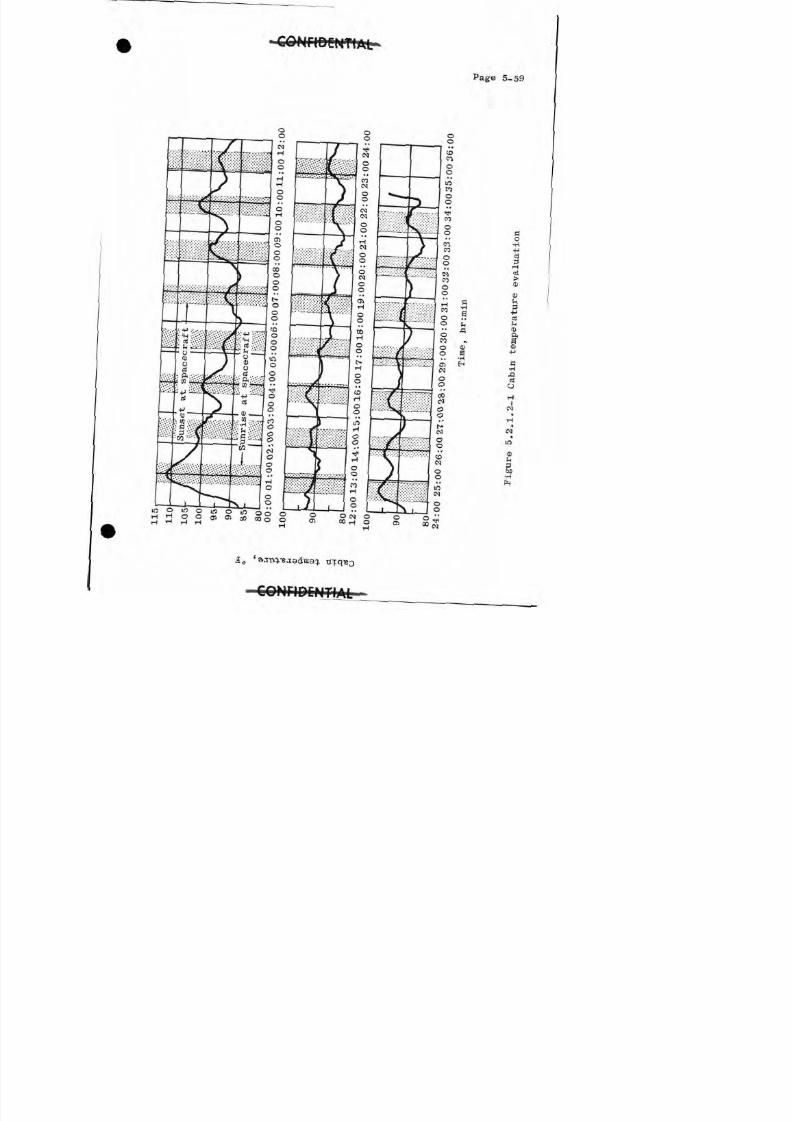
8/7/2019 Post Launch Memorandum Report for Mercury-Atlas No. 9(MA-9). Part 1 Mission Analysis
http://slidepdf.com/reader/full/post-launch-memorandum-report-for-mercury-atlas-no-9ma-9-part-1-mission 127/344
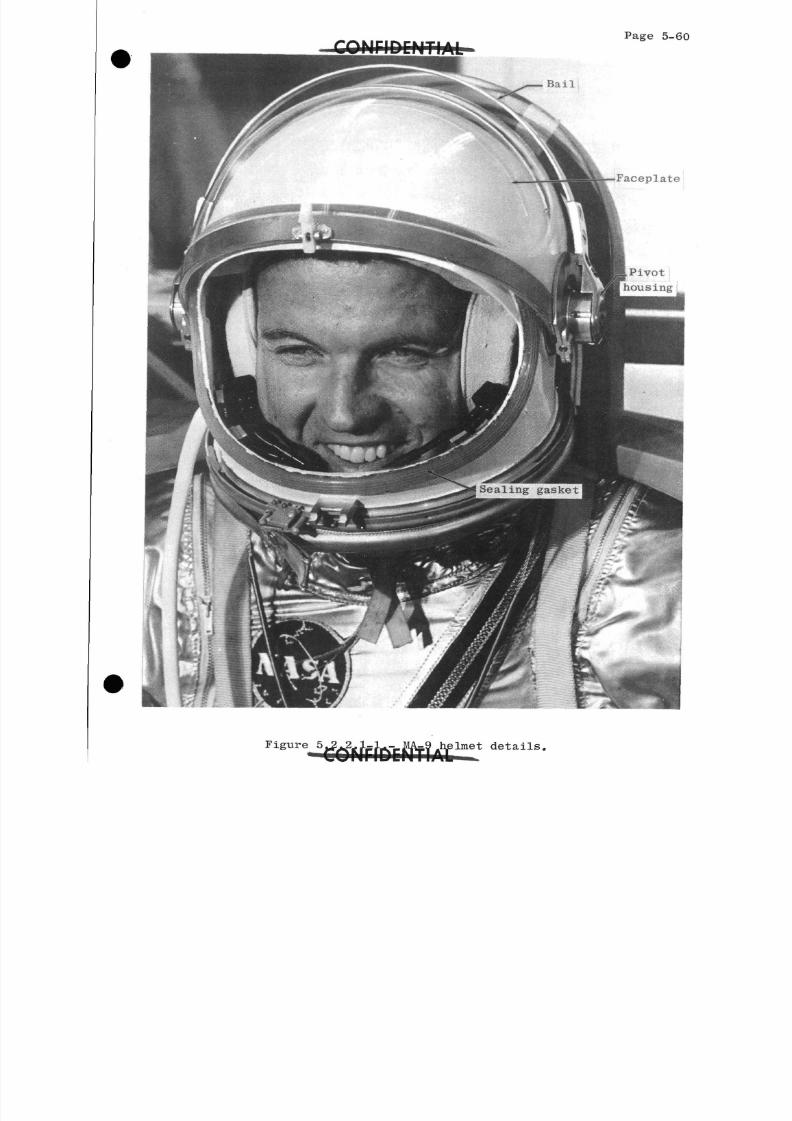
8/7/2019 Post Launch Memorandum Report for Mercury-Atlas No. 9(MA-9). Part 1 Mission Analysis
http://slidepdf.com/reader/full/post-launch-memorandum-report-for-mercury-atlas-no-9ma-9-part-1-mission 128/344
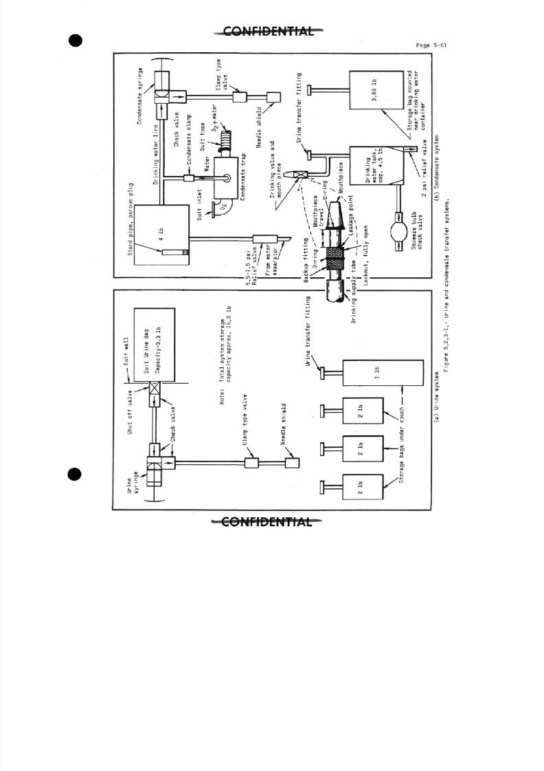
8/7/2019 Post Launch Memorandum Report for Mercury-Atlas No. 9(MA-9). Part 1 Mission Analysis
http://slidepdf.com/reader/full/post-launch-memorandum-report-for-mercury-atlas-no-9ma-9-part-1-mission 129/344
C Q N r i D C M T I A LP a g e 5-61
.H
•H
*-H
cn
i0)
rt
44-
0
D.CLO
(D
=
0)
rtm
VC
i
D7*=
c
(0
"- J
< 1
CO
CO1
-M
OOf
0.
CD
5
a>
3tca
c.
r
= '
-^
D>
C
<r> M -0) -OHO 1_
« i-H 01l_ 4-
o . at-H X Cu) 0 rt
< u a.-H CS 0)(0 C.
- "=V
4 5£ Tf g L
f, 0)
0 >H
« -n f]
3S . 2 -L I>> U)
<DOU rH
E T3
X XD
1 rn -~n~i| l_J LJ
i i_i
i=
i=
N
c
c
1-ca
i-H
r
rH
00
rH
(M
00
|
1
.C
^. Us. ^
o
(UT3
D
^ S )ft
a>rt
^
•acrt
0)c
i,n
i
H1
CO
CM
in
0)i_
D»
U_
E03+-•
>.W
(U
LZ3
rt
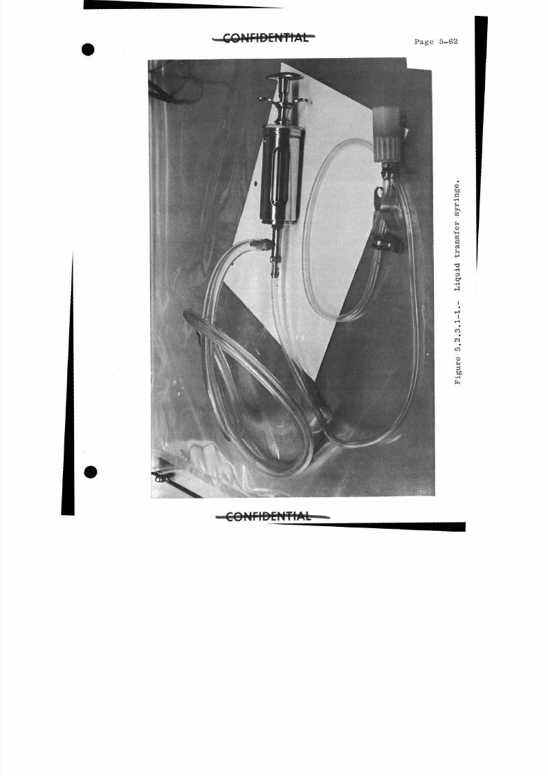
8/7/2019 Post Launch Memorandum Report for Mercury-Atlas No. 9(MA-9). Part 1 Mission Analysis
http://slidepdf.com/reader/full/post-launch-memorandum-report-for-mercury-atlas-no-9ma-9-part-1-mission 130/344
Page 5-62
< Db fla•H
CO
< D< Hmaa
o1
•H
HI
CO
•
C S1
bfl•H
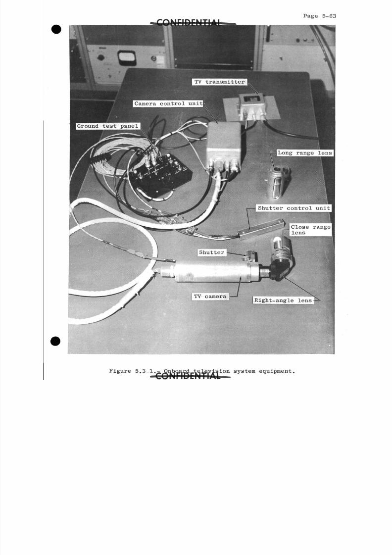
8/7/2019 Post Launch Memorandum Report for Mercury-Atlas No. 9(MA-9). Part 1 Mission Analysis
http://slidepdf.com/reader/full/post-launch-memorandum-report-for-mercury-atlas-no-9ma-9-part-1-mission 131/344
Page 5-6
TV transmitter
Camera control unit
Ground test panel
Long range lens
Shutter control unit
[j Close rangelens
TV cameraRight-angle lens
Figure 5.3-1. ision system equipment.
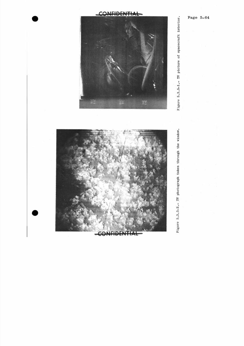
8/7/2019 Post Launch Memorandum Report for Mercury-Atlas No. 9(MA-9). Part 1 Mission Analysis
http://slidepdf.com/reader/full/post-launch-memorandum-report-for-mercury-atlas-no-9ma-9-part-1-mission 132/344
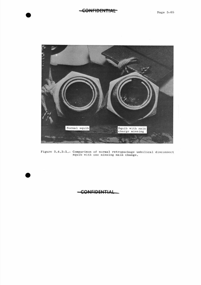
8/7/2019 Post Launch Memorandum Report for Mercury-Atlas No. 9(MA-9). Part 1 Mission Analysis
http://slidepdf.com/reader/full/post-launch-memorandum-report-for-mercury-atlas-no-9ma-9-part-1-mission 133/344
C O N F I D E N T I A L Page 5-6
Squib with maincharge missing
Figure 5.4.3-1.- Comparison of normal retropackage umbilical disconnecsquib with one missing main change.
r*/*\M IPtCMTI A I
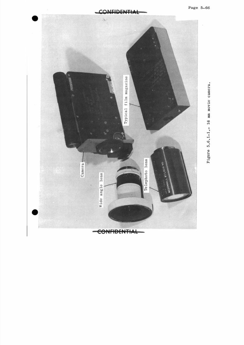
8/7/2019 Post Launch Memorandum Report for Mercury-Atlas No. 9(MA-9). Part 1 Mission Analysis
http://slidepdf.com/reader/full/post-launch-memorandum-report-for-mercury-atlas-no-9ma-9-part-1-mission 134/344
Page 5-6
C O N r i D C H T I A L -
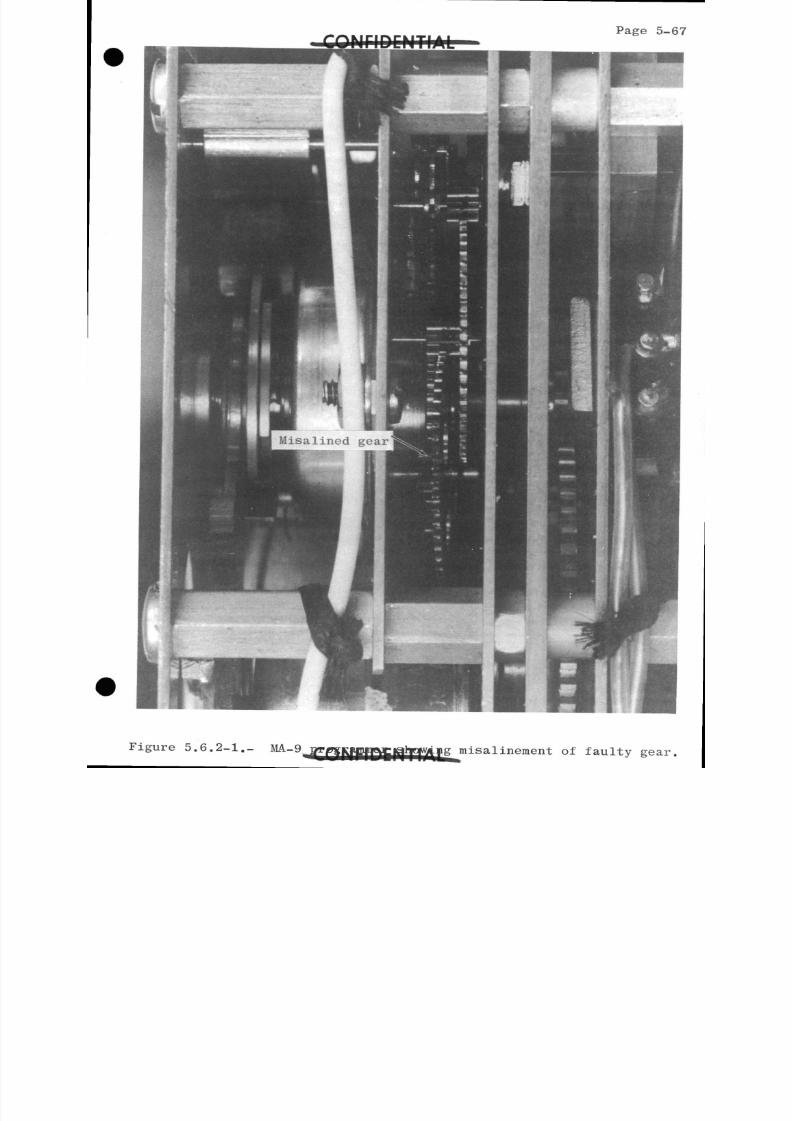
8/7/2019 Post Launch Memorandum Report for Mercury-Atlas No. 9(MA-9). Part 1 Mission Analysis
http://slidepdf.com/reader/full/post-launch-memorandum-report-for-mercury-atlas-no-9ma-9-part-1-mission 135/344
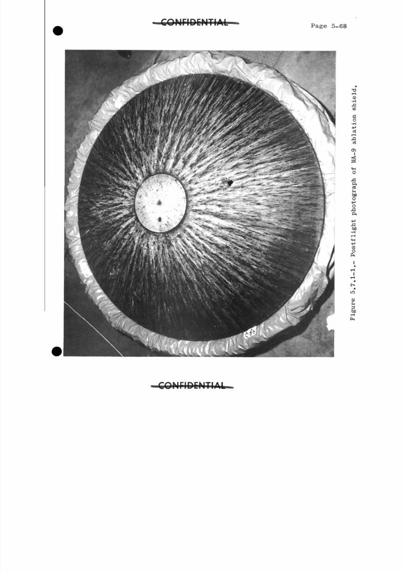
8/7/2019 Post Launch Memorandum Report for Mercury-Atlas No. 9(MA-9). Part 1 Mission Analysis
http://slidepdf.com/reader/full/post-launch-memorandum-report-for-mercury-atlas-no-9ma-9-part-1-mission 136/344
S O N r i D C M T I A L Page 5-6
FNCMTAI
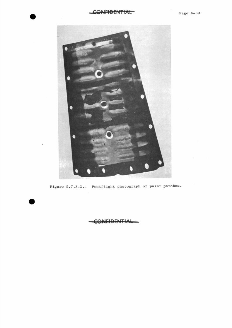
8/7/2019 Post Launch Memorandum Report for Mercury-Atlas No. 9(MA-9). Part 1 Mission Analysis
http://slidepdf.com/reader/full/post-launch-memorandum-report-for-mercury-atlas-no-9ma-9-part-1-mission 137/344
Page 5-6
Figure 5.7.3-1.- Postflight photograph of paint patches,
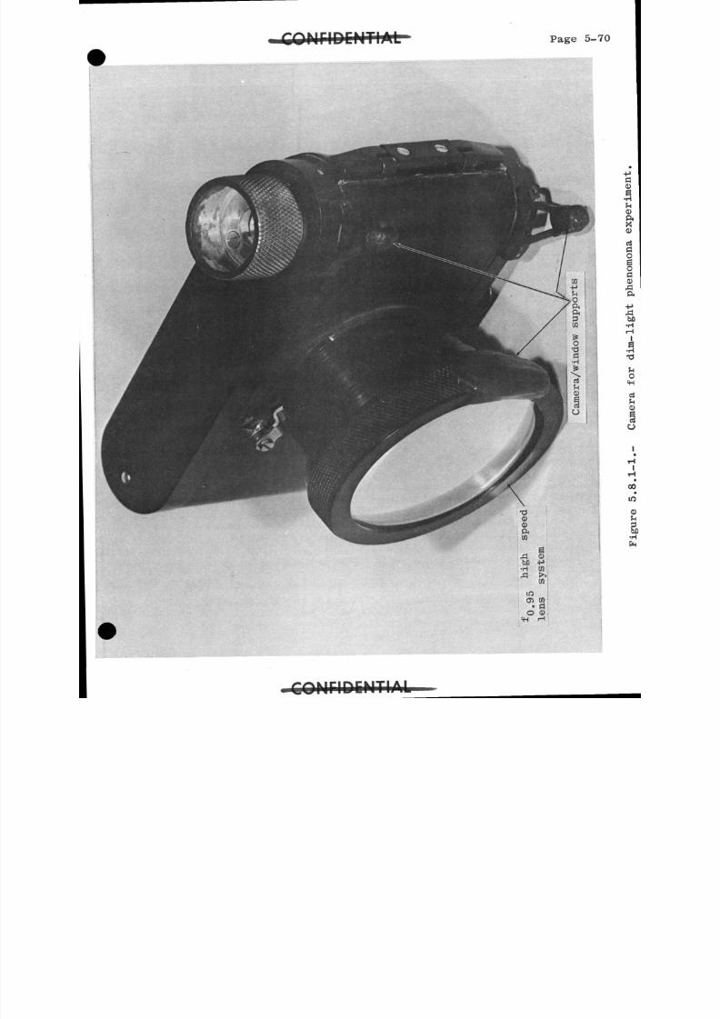
8/7/2019 Post Launch Memorandum Report for Mercury-Atlas No. 9(MA-9). Part 1 Mission Analysis
http://slidepdf.com/reader/full/post-launch-memorandum-report-for-mercury-atlas-no-9ma-9-part-1-mission 138/344
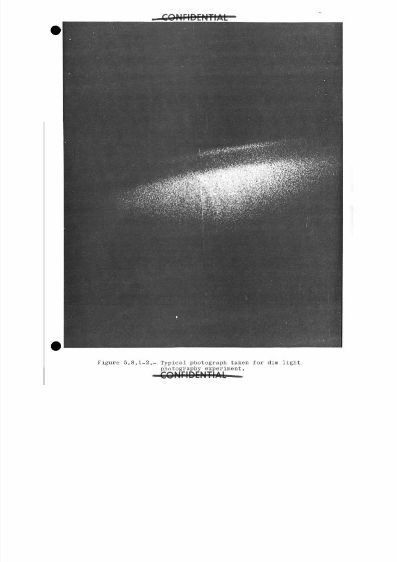
8/7/2019 Post Launch Memorandum Report for Mercury-Atlas No. 9(MA-9). Part 1 Mission Analysis
http://slidepdf.com/reader/full/post-launch-memorandum-report-for-mercury-atlas-no-9ma-9-part-1-mission 139/344
Figure 5.8.1-2.- Typical photograph taken for dim light
photography experiment.
J l
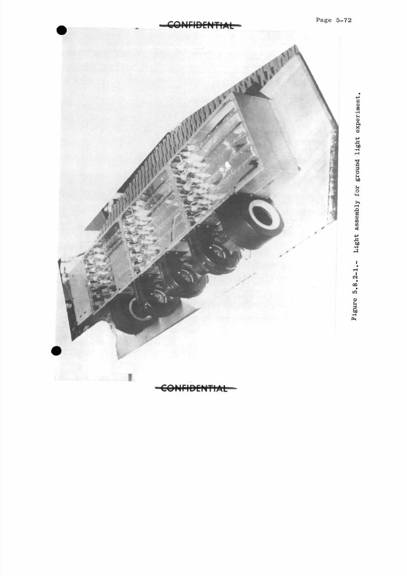
8/7/2019 Post Launch Memorandum Report for Mercury-Atlas No. 9(MA-9). Part 1 Mission Analysis
http://slidepdf.com/reader/full/post-launch-memorandum-report-for-mercury-atlas-no-9ma-9-part-1-mission 140/344
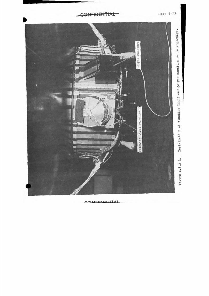
8/7/2019 Post Launch Memorandum Report for Mercury-Atlas No. 9(MA-9). Part 1 Mission Analysis
http://slidepdf.com/reader/full/post-launch-memorandum-report-for-mercury-atlas-no-9ma-9-part-1-mission 141/344
Page 5-7
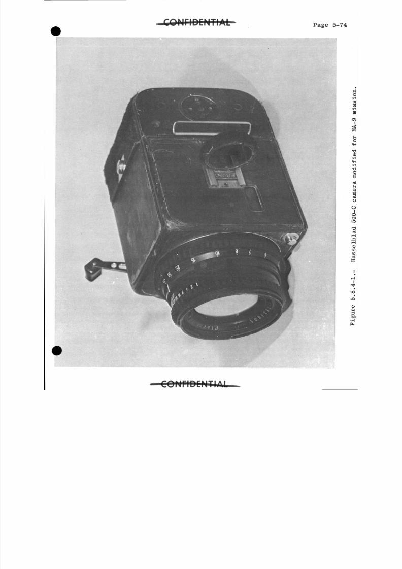
8/7/2019 Post Launch Memorandum Report for Mercury-Atlas No. 9(MA-9). Part 1 Mission Analysis
http://slidepdf.com/reader/full/post-launch-memorandum-report-for-mercury-atlas-no-9ma-9-part-1-mission 142/344
Page 5-7
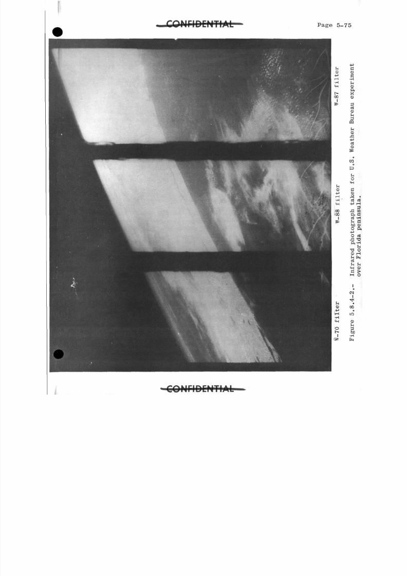
8/7/2019 Post Launch Memorandum Report for Mercury-Atlas No. 9(MA-9). Part 1 Mission Analysis
http://slidepdf.com/reader/full/post-launch-memorandum-report-for-mercury-atlas-no-9ma-9-part-1-mission 143/344
Page 5-
C O M r i D C M T I A L -
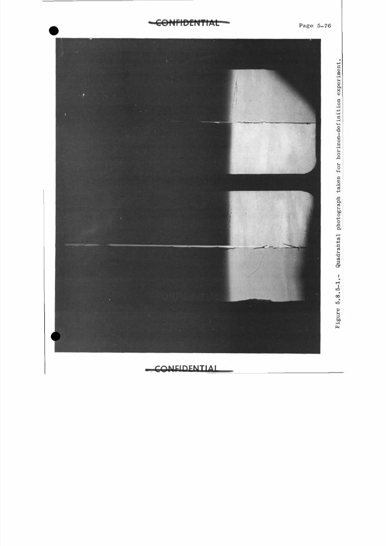
8/7/2019 Post Launch Memorandum Report for Mercury-Atlas No. 9(MA-9). Part 1 Mission Analysis
http://slidepdf.com/reader/full/post-launch-memorandum-report-for-mercury-atlas-no-9ma-9-part-1-mission 144/344
£OHflDCNTIAL Page 5-7
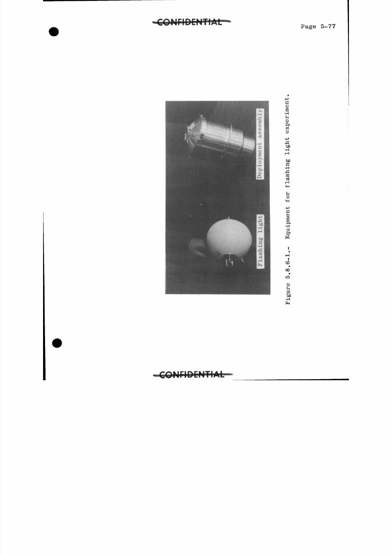
8/7/2019 Post Launch Memorandum Report for Mercury-Atlas No. 9(MA-9). Part 1 Mission Analysis
http://slidepdf.com/reader/full/post-launch-memorandum-report-for-mercury-atlas-no-9ma-9-part-1-mission 145/344
Page 5-7
S30fi•Hh0O,X0
bOa•H
^5C O
ea•H
3a
1
00•
m
0
(H
C O M r i D C M T I j f l i L
8/7/2019 Post Launch Memorandum Report for Mercury-Atlas No. 9(MA-9). Part 1 Mission Analysis
http://slidepdf.com/reader/full/post-launch-memorandum-report-for-mercury-atlas-no-9ma-9-part-1-mission 146/344
Page 5-78
8/7/2019 Post Launch Memorandum Report for Mercury-Atlas No. 9(MA-9). Part 1 Mission Analysis
http://slidepdf.com/reader/full/post-launch-memorandum-report-for-mercury-atlas-no-9ma-9-part-1-mission 147/344
C O N F I D E N T I A L
Page 5-79
8/7/2019 Post Launch Memorandum Report for Mercury-Atlas No. 9(MA-9). Part 1 Mission Analysis
http://slidepdf.com/reader/full/post-launch-memorandum-report-for-mercury-atlas-no-9ma-9-part-1-mission 148/344
8/7/2019 Post Launch Memorandum Report for Mercury-Atlas No. 9(MA-9). Part 1 Mission Analysis
http://slidepdf.com/reader/full/post-launch-memorandum-report-for-mercury-atlas-no-9ma-9-part-1-mission 149/3445.8.8-1.- Photograph of Himalaya Moi i taken with BasseIblad camera.
8/7/2019 Post Launch Memorandum Report for Mercury-Atlas No. 9(MA-9). Part 1 Mission Analysis
http://slidepdf.com/reader/full/post-launch-memorandum-report-for-mercury-atlas-no-9ma-9-part-1-mission 150/344
8/7/2019 Post Launch Memorandum Report for Mercury-Atlas No. 9(MA-9). Part 1 Mission Analysis
http://slidepdf.com/reader/full/post-launch-memorandum-report-for-mercury-atlas-no-9ma-9-part-1-mission 151/344
6 - 2 C O N F I D E N T I A L
probe in the sustainer-engine lubricant tank, vhich was also installed in
the engine compartment, was used for the first time in this location. The
probe sensed temperatures of 50° F at lift-off, 70° F at BECO, and 9 ° F
at SECO. This transducer was shielded from thermal radiation and provided
a temperature study of the lubricant as it is consumed.
6.3 Propellant Tanking
The tanking of EP-1 fuel to the 100-percent probe resulted in a total
fuel quantity at 80° F of 11, 28 gallons, which corresponded to an indi-
cated weight increase of 76,500 pounds. Following the countdown for lox
tanking, a drop in fuel temperature and a resultant density increase re-
quired the addition of 350 pounds of fuel to reestablish the 100-percent
level. Final fuel weight, adjusted to include the weighing system cali-
bration, gravity correction, and pressurization gas weight, was 7 ,900
pounds.
Lox tanking to the 100-percent probe required 17 ,000 pounds oflox.
Subcooled topping was added to maintain an indicated lox weight constant
at 17^-, 100 pounds. After securing lox tanking, 500 pounds of lox were
calculated to have been lost through the vernier-engine bleed valves and
the start tank vent.
Following final pressurization, the lox level was above the high-level
probe for approximately 10 seconds. However, this level was between the
high- and low-level probes at ignition because of boil-off. The total
weight of the spacecraft and launch vehicle at ignition was 326, 00 pounds.
6.k Propellant Utilization
The propellant utilization (PU) valve operated normally within the
dynamic range up to approximately 35 seconds prior to SECO. At this time,
the valve followed corrections to near-nominal values over a 10-second
period prior to SECO. At this point, the PU valve followed the bias in-
troduced by the capacitancepad.
The fuel and lox-head pressure-sensing ports were uncovered at 3-25
and 6.85 seconds, respectively, prior to SECO. Propellant residuals at
SECO were calculated to be 83.6 pounds of lox and 5 0.6 pounds of fuel.
6.5 Pneumatics
The lox-and fuel-tank ullage pressures were within normal operating
limits throughout the flight. Booster-tank helium-bottle decay was normal
and the sustainer-tank helium bottle maintained adequate pressure.
C O N F I D E N T I A L
8/7/2019 Post Launch Memorandum Report for Mercury-Atlas No. 9(MA-9). Part 1 Mission Analysis
http://slidepdf.com/reader/full/post-launch-memorandum-report-for-mercury-atlas-no-9ma-9-part-1-mission 152/344
8/7/2019 Post Launch Memorandum Report for Mercury-Atlas No. 9(MA-9). Part 1 Mission Analysis
http://slidepdf.com/reader/full/post-launch-memorandum-report-for-mercury-atlas-no-9ma-9-part-1-mission 153/344
p a g e 6 - k G O f f r i D C H T I A L . » .
6.8 Guidance
The launch-vehicle radio-guidance system performed veil and guided
the sustainer stage to near-nominal cutoff conditions that were veil
within the acceptable limits. The radar data were of good quality and
exhibited lov noise. The errors at insertion were 1.3 ft/sec low in velocity,1,333 feet high in altitude, and 0.0031° high in flight-path angle.
The guidance-system configuration was similar to that used in the
MA-8 mission except that the duration of the second-stage pitch program
was reduced by 5-0 seconds, resulting in 10° less pitch-down maneuver, and
the ground guidance computer equations were changed. The reduction in the
pitch programer duration gives a more efficient trajectory. Hovever, the
MA-8 capability of reaching acceptable orbital insertion conditions for a
near-nominal trajectory with a loss of closed-loop launch-vehicle guidance
steering vas not maintained.
A somewhat depressed trajectory was flown throughout the flight.The BECO discrete signal was 0.5 second early, the velocity was high, and
the altitude was low at staging. These conditions resulted in SECO being
1. U seconds early. The radar elevation angle at SECO was a nominal1. °.
The guidance system acquired the track beacon of the launch vehicle
in the first radar cube, and lock was continuous from 00:01:04.0 to
00:06:07.1 (6k sec after SECO). Rate lock was continuous in all functions
from 00:00:58.3 to 00:05:55.7 (53 sec after SECO), except for 0.1 second
of bad central rate data 3-7 seconds after BECO. These bad data were caused
by the jettisoned booster stage assembly's passing between the ground radar
and the airborne transponder. The bad data had no effect on the flight of
the launch vehicle, since guidance steering was not initiated until
22.8 seconds later.
Closed-loop radar guidance steering started at 00:02:38.8 with a
25-percent positive pitch rate and a 30-percent positive yaw rate. This
yaw right maneuver corrected a booster-stage roll program error. There-
after, the commands were smooth and small until 5-5 seconds prior to SECO
when 25-percent pitch steering commands were sent to the launch vehicle
to correct the error in flight-path angle. Noise in the steering commands
was lower than for all previous Mercury-Atlas orbital missions.
The ground guidance computer equations had been changed since MA-8
to extrapolate radar data better and to smooth out radar noise. Guidance
initiation was started on slant range rather than on time after BECO.
Other than these changes, the application of these equations was the same
in the normal data mode. The reason for these changes was to give better
steering commands in the event of noise resulting in the loss of radar
data.
In figures 6.8-1 and 6.8-2, the velocity and flight-path angle are
shown in the region of sustainer engine cutoff. The launch-vehicle data
8/7/2019 Post Launch Memorandum Report for Mercury-Atlas No. 9(MA-9). Part 1 Mission Analysis
http://slidepdf.com/reader/full/post-launch-memorandum-report-for-mercury-atlas-no-9ma-9-part-1-mission 154/344
Page 6 - 5
are shown in figure 6. 8-1, and the range safety impact predictor computer
(I. P. 709*0 data are shown in figure 6.8-2 to illustrate the data quality
during the time of the go no-go computations. Both data sources exhibited
low noise and the average of these values agrees with the actual flight
conditions. One launch vehicle guidance data point was not received by
the Goddard computer at 00:05:08.07; however, a 20-point average was stillused. Maximum peak-to-peak deviations in the launch-vehicle guidance data
were about one-quarter of the magnitude experienced on MA.-4 and MA-8 and
about one-half the noise level of MA-5, MA-6,and MA-7. The IP-709 data
noise level was about half that experienced on MA.-4 and MA-8and about the
same as MA-5, MA-6,andMA-7.
In figure 6.8-3, "the variation of flight-path angle with velocity is
the type of display used by the Flight Dynamics Officer in the Mercury
Control Center for the orbital gono-go decision. Both the launch -vehicle
guidance and HP-709 data indicated acceptable conditions.
6.9 Abort Sensing and Implementation System
The ready status of the abort sensing and implementation system was
properly established at 0.8 second prior to lift-off. Telemetry records
indicate that the pressure switches operated correctly. Wo system
parameters reached the abort level, and no abort command was generated
during powered flight. After SECO, the system indicated an abortcon-
dition, which is an expected occurrence and results from a decay in the
engine fuel pressure. An incomplete listing of the proximity of monitored
parametric values to the specified limits for the MA-9abort system is
presented as follows:
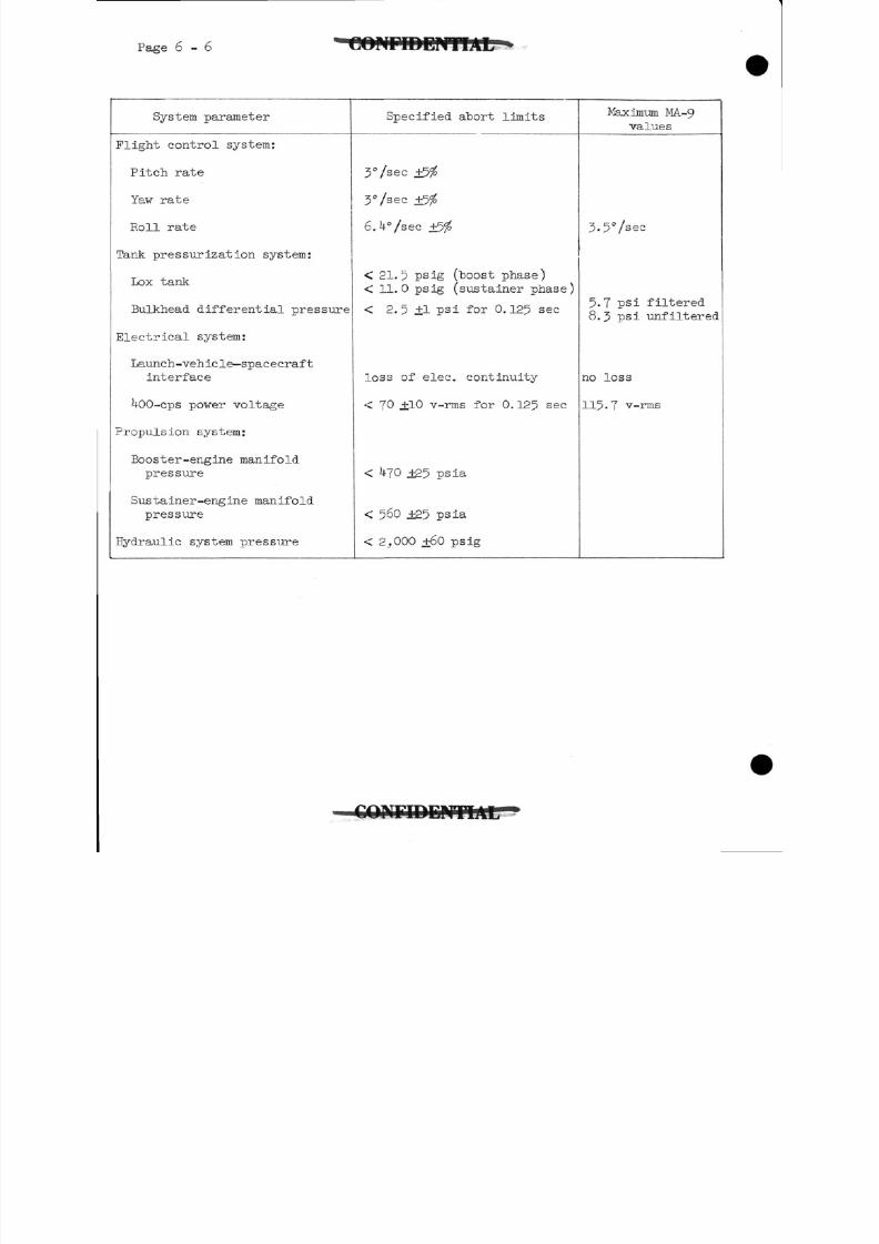
8/7/2019 Post Launch Memorandum Report for Mercury-Atlas No. 9(MA-9). Part 1 Mission Analysis
http://slidepdf.com/reader/full/post-launch-memorandum-report-for-mercury-atlas-no-9ma-9-part-1-mission 155/344
Page 6-6
System parameter Specified abort limits Maximum MA-9
values
control system:
Pitch rate
Yaw rate
Roll rate
Lox tank
Bulkhead differential pressure
Launch-vehiclespacecraft
interface
400-cps power voltage
system:
Booster-engine manifold
pressure
Sustainer-engine manifold
pressure
aulic system pressure
3'/ ec
3%ec
3-5°/sec
< 21.5 psig (boost phase)
< 11.0 psig (sustainer phase)
< 2.5+1 psi for 0.125 sec
loss of elec. continuity
< 70 +10 v-rms for 0. 125 sec
5.7 psi filtered
8.3 psi unfiltered
no loss
115.7 v-rms
+25 psia
< 560 ±25 psia
< 2,000 +60 psig
CONriDDMTIAtr
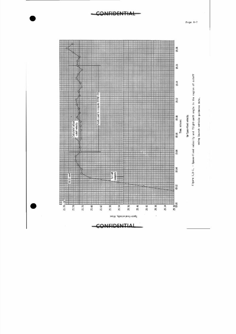
8/7/2019 Post Launch Memorandum Report for Mercury-Atlas No. 9(MA-9). Part 1 Mission Analysis
http://slidepdf.com/reader/full/post-launch-memorandum-report-for-mercury-atlas-no-9ma-9-part-1-mission 156/344
O N F I D E N T I A L
P a g e 6-7
o
01
racOS
£ £« S.« I> +j
^ D>
roc
CO
oa s / y '
Al
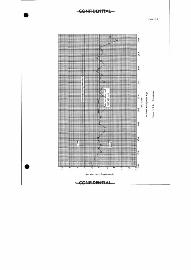
8/7/2019 Post Launch Memorandum Report for Mercury-Atlas No. 9(MA-9). Part 1 Mission Analysis
http://slidepdf.com/reader/full/post-launch-memorandum-report-for-mercury-atlas-no-9ma-9-part-1-mission 157/344
8/7/2019 Post Launch Memorandum Report for Mercury-Atlas No. 9(MA-9). Part 1 Mission Analysis
http://slidepdf.com/reader/full/post-launch-memorandum-report-for-mercury-atlas-no-9ma-9-part-1-mission 158/344
P a g e . 6 -
0101
ai-H01ca
8
"8><
S-ocOS
01
X
< aoao-
(MI
CO
ID
0)
a
3 8 S / U 'A)po|8A
A I
8/7/2019 Post Launch Memorandum Report for Mercury-Atlas No. 9(MA-9). Part 1 Mission Analysis
http://slidepdf.com/reader/full/post-launch-memorandum-report-for-mercury-atlas-no-9ma-9-part-1-mission 159/344
8/7/2019 Post Launch Memorandum Report for Mercury-Atlas No. 9(MA-9). Part 1 Mission Analysis
http://slidepdf.com/reader/full/post-launch-memorandum-report-for-mercury-atlas-no-9ma-9-part-1-mission 160/344
P a g e 6-11
\
CD
(D
B a p ps x | j.-
r-t. IT-I A i
8/7/2019 Post Launch Memorandum Report for Mercury-Atlas No. 9(MA-9). Part 1 Mission Analysis
http://slidepdf.com/reader/full/post-launch-memorandum-report-for-mercury-atlas-no-9ma-9-part-1-mission 161/344
8/7/2019 Post Launch Memorandum Report for Mercury-Atlas No. 9(MA-9). Part 1 Mission Analysis
http://slidepdf.com/reader/full/post-launch-memorandum-report-for-mercury-atlas-no-9ma-9-part-1-mission 162/344
p a g e 7 - 1
7-0 ASTRONAUT ACTIVITIES
This section contains a detailed analysis of the physiological
responses of the astronaut, an evaluation of his performance in com-
pleting the prescribed flight plan, and a flight report "by the astronaut,The aeromedical analysis documents the preflight medical activities,
the inflight responses, and the postflight examinations; and conclusions
derived from the analysis of these data are presented. The astronaut's
performance is evaluated from the standpoint of his ability to maneuver
the spacecraft, manage the operation of the onboard systems, conduct
scientific experiments, and in general complete scheduled .activities.
This section is concluded with a narrative account by the astronaut of
his flight experience and his evaluation of many operational aspects of
the mission.
7-1 Aeromedical Analysis
7.1.1 Introduction.- The MA-9 flight represents another step in
the serial extension of the observation of man as he functions
under the physical stresses of zero gravity, decreased ambient
pressure, and a pure oxygen environment, and under the psychologica
stress of this remarkable experience with the multitude of
risks involved.
The step-wise extension of the mission durations produces
an increasing understanding of man's adaptation to, and
toleration of, this new environment. Application of this
information enhances the confidence in and understanding of
future missions of greater duration. The purpose of this
section of the report is to present the qualitative and
quantitative medical analysis conducted within the Project
Mercury mission framework and thus to indicate the present
state of medical efforts in the area of manned space flight.
The report is presented chronologically in the three categories
of preflight, inflight, and postflight findings. Within each
of these broad areas the data are presented in two parts:
results of clinical studies, both of a conventional nature
and selected special procedures; and results of biosensor
monitoring studies. The concluding portion presents a series
of special medical studies for the MA-9 mission.
The intimate interaction of the pilot and his environmental
control system requires that the discussion of the Life Support
System (Section 5-2) be considered in conjunction with the
Aeromedical Analysis.
C O N F I D E N T I A L
8/7/2019 Post Launch Memorandum Report for Mercury-Atlas No. 9(MA-9). Part 1 Mission Analysis
http://slidepdf.com/reader/full/post-launch-memorandum-report-for-mercury-atlas-no-9ma-9-part-1-mission 163/344
Page 7-2
7-1.2 Preflight observation.-
7.1.2.1 Clinical data: Data were evaluated from very thorough medical
studies of the pilot, Astronaut L. Gordon Cooper, Jr., conducted
immediately prior to his selection for astronaut training in
1959 and from annual examinations since that date. Medicalexaminations were also conducted both before and after six
preflight spacecraft checkout tests and a session in the
Mission Control Center procedures trainer, all of which required
the pilot to wear the full-pressure space suit. Special
examinations to assess the pilot's fitness for flight were
conducted 11 and 3 days before launch. The latter examination
conducted on May 12, 1963, designated the "Comprehensive
Medical Evaluation," was conducted by specialists in internal
medicine, ophthalmology, neuropsychiatry, radiology, and
aviation medicine. The NASA Flight Surgeon who had examined
the pilot for most of the preflight activities conducted the
final preflight medical examination on launch morning. Thepreflight aeromedical procedures and examinations are listed
in table 7.1.2.1-1.
The astronaut's pertinent medical history is summarized here
as background medical data. At age 6 he contracted pneumonia
of the left lung, followed by empyema and requiring surgical
drainage. He has residual non-symptomatic adhesions and
thickening of the left lateral pleura and there is a well
healed linear 5 cm scar in the skin at the 9~th posterior
intercostal space at the surgical drainage site. Neither
complications nor sequellae have occurred as a result of this
condition, and repeated pulmonary function studies have beennormal. On November 3? I960, a cholecystectomy and incidental
appendectomy were performed following X-ray demonstration of
cholelithiasis. Full recovery was prompt and no food
intolerance or other sequellae have occurred. He has moderate
seasonal rhinitis relieved by small doses of common
antihistamines. In the three months prior to the MA-9 flight
no antihistaminic medication was required. The pilot
exhibited a gastrointestinal intolerance, evidenced by
cramping abdominal pains, to an oral test dose of morphine
sulfate. This reaction is seen in a small percentage of
normal people. Other than the foregoing items, the pilot's
medical history is not significant.
In addition to examinations by physicians, baseline clinical
evaluations included an audiogram, an electrocardiogram, a
chest X-ray and laboratory studies of blood and urine. The
results of these evaluations are found in tables 7-1-2.1-2
through 7.1.2.1-5. For the 3 months prior to the flight,
the pilot continued in excellent health with significant
abnormalities.
C O N F I D E N T I A L
8/7/2019 Post Launch Memorandum Report for Mercury-Atlas No. 9(MA-9). Part 1 Mission Analysis
http://slidepdf.com/reader/full/post-launch-memorandum-report-for-mercury-atlas-no-9ma-9-part-1-mission 164/344
O T I D C M T 1 A L * p a g e 7 3
Close supervision of the pilot's food intake began 7 days before
the planned flight with special preparation of a normal
balanced diet. To reduce the need for defecation during the
mission, a low residue diet was followed for 4 days before the
launch. This diet was well tolerated, although the pilot did
mention that appetite satisfaction was short-lived following
the low residue meals. The constituents, both qualitative and
quantitative, of this diet are presented in table 7.1.2.1-6.
In the month prior to flight, he maintained his physical
fitness by daily distance running and calisthenics.
The aeromedical countdown, table 7-1-2.1-Tj presents the pilot's
activities on launch morning. Compared with the pilots in
previous orbital missions, the MA-9 astronaut spent the
shortest time (5 hours and 1J minutes) from awakening to
lift-off. In spite of a last minute requirement for an earlier
insertion, all elements of the aeromedical countdown were
accomplished satisfactorily without altering the planned
wake-up time.
The final prelaunch examination showed a healthy pilot who was
ready for the mission. Two minor discrepancies were local skin
erythema at the biosensor sites and moderate erythema,
edema, and tenderness of the skin over the right sacral
prominence. He frequently demonstrates a skin reaction around
the sensors for 2k to j6 hours after application, despite the
use of microporous surgical tape for fastening these sensors.
It should be noted that these sensors were in place for
7 hours during the canceled launch on the preceding day. The
skin findings over the sacrum are frequently present following
prolonged periods of 4 or more hours on his back in the couch.
On the night before the postponed launch of May 1 -,19 3, the
pilot slept well for about two hours and then dozed fitfully
for another 3 - hours. He had several dreams related to
problems with the use of the flight plan and the inflight
medications and also later reported he did not feel rested.
However, on the night before the successful launch, he slept
well for 6 hours and no dreams were recalled. Although he
did become sleepy during periods of relative inactivity,such as in the transfer van, he did feel adequately rested
on launch morning. At no time was a drug administered to
induce sleep.
7-1.2.2 Biosensor data: The sources of detailed biosensor data are
outlined in tables 7.1.2.2-1 and 7.1.2.2-2. These sources
include dynamic tests for evaluation of general physical
8/7/2019 Post Launch Memorandum Report for Mercury-Atlas No. 9(MA-9). Part 1 Mission Analysis
http://slidepdf.com/reader/full/post-launch-memorandum-report-for-mercury-atlas-no-9ma-9-part-1-mission 165/344
8/7/2019 Post Launch Memorandum Report for Mercury-Atlas No. 9(MA-9). Part 1 Mission Analysis
http://slidepdf.com/reader/full/post-launch-memorandum-report-for-mercury-atlas-no-9ma-9-part-1-mission 166/344
Page 7-5
The preflight biosensor data are presented in tables 7.1.2.2-1
to 7-1.2.2-k. The analysis methods used were both manual and
automatic.
All respiration minute rates were obtained by 30-second
counts made from the continuous direct-recorded analog signal,with sampling intervals either every 3 or every k minutes.
Heart rates were determined in the same manner by counting
manually; those sets can be readily identified by the
relatively low number of values used. The automatic analysis
utilizes a general purpose computer to determine the intervals
between all the R waves of the EGG complexes in the record,
and the reported values are computed from these determinations.
The automatically reduced rates are readily identified by the
large numbers of values . The validity of both of these methods
has been substantiated by repeated cross-correlation of results
during the two years of development of the analysis program.
Although the data analysis format was arbitrarily selected,the results are fully reproducible and appear to be adequate
for the present medical requirements. All blood pressures
on record were incorporated in the tables.
The most significant aspect of the preflight data is the
rather wide range of mean rates, particularly heart rates,
which limits the establishment of expected or so-called normal
responses . This wide variation is a common phenomenon among
healthy individuals and, in this regard, makes it difficult
to predict accurately the responses of such a person under
conditions similar to those during which the background data
are derived.
The EGG from the preflight observation period was scanned
repeatedly by numerous observers. The collective opinions
were that marked normal sinus arrhythmia was present with
frequent occurrences of a wandering cardiac pacemaker. At
times, sinus node suppression was sufficient to allow
activation by the atrio-ventricular (A-V) node with escape and
fusion beats. This occurrence was identified by both biphasic
and negative P waves of decreased amplitude, and on occasion
by changes in the ventricular complexes. There were numerous
such beats noted during the countdown of the postponed launch,
and there was one brief episode of nodal rhythm during this
period. These data are illustrated in figure 7.1.2.2-3 and
7.1.2.2-^4-. There was sinus bradycardia, which, at times,
was followed by a sinus-generated beat and, at other times,
an A-V nodal-generated escape beat. Other infrequent rhythm
alterations were premature atrial and ventricular beats.
These preflight data were collected in order to establish
the baseline physiological responses of the MA-9 astronaut
specifically using the flight biomedical instrumentation.
O O M F I D E M T I A L
8/7/2019 Post Launch Memorandum Report for Mercury-Atlas No. 9(MA-9). Part 1 Mission Analysis
http://slidepdf.com/reader/full/post-launch-memorandum-report-for-mercury-atlas-no-9ma-9-part-1-mission 167/344
p a g e 7 - 6 C O N F I D E N T I A L
7.1.3 Flight observations.-
7.1.3.1 Biosensor data: Inflight biomedical monitoring spanned a
time interval of 3^ hours, l6 minutes,, and ^3 seconds on this
flight. Continuous onboard recording included the first
1 hour and 35 minutes and the last 10 hours and 5 minutes offlight time until bioplug disconnect. Flight data were
programed to be intermittently recorded for 1 minute of every
10 minutes between 1 hour and 39 minutes elapsed time and
23 hours and 32 minutes elapsed time. Recording of physiolgical
data through the mid-portion of the flight was erratic and
did not follow original plans because of a malfunction of the
tape-recorder programer which occurred at approximately
12:00:00 and continued throughout the flight. Data during
the final portion of the flight, from 24:00:00 until landing,
were made possible because the failed programer was overriden
by the astronaut's selection of continuous recorder operations.
However, sufficient data points were obtained for confidentextrapolation of trends of physiologic values during such periods
by the astronaut's voice contacts with the ground, use of the
vox-record actuation of the tape recorder, or turning the
tape recorder temporarily to continuous to document certain
inflight experiments. During the period when the astronaut
was resting quietly or was asleep, essentially no medical
data were obtained on the onboard recorder; consequently mean
heart rate values for the entire duration of the flight are
probably biased on the high side of a true mean. Data from
the onboard recorder have been supplemented by data obtained
during network station passes throughout the mission, and an
exceptionally valuable short period of recording was obtainedonboard the carrier during egress of the astronaut. The
inflight responses are summarized in tables 7-1-2.2-2 and
7.1.2.2-4. Hear rate response, including mean rates, was
obtained through a computer reduction of the inflight data
from the onboard tape recorder.
Respiration rates were obtained by the manual counting of
30-second periods every 3 minutes during the period of
continuous recording, and from 30-second averages taken at
all other short intervals when data were available from the
onboard tape recorder. Blood pressures were obtained according
to the flight plan with only very minor variations. Thesevalues were with few exceptions not recorded on the onboard
recorder since the astronaut was generally quiet while sending
the blood pressure, and therefore the tape recorder was not
operating. However, the values were received at ground
stations in every instance and read in real time by medical
monitors. The readings were subsequently verified by
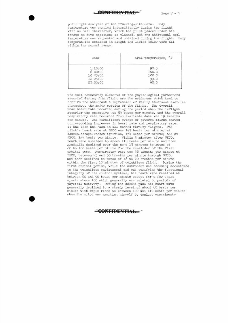
8/7/2019 Post Launch Memorandum Report for Mercury-Atlas No. 9(MA-9). Part 1 Mission Analysis
http://slidepdf.com/reader/full/post-launch-memorandum-report-for-mercury-atlas-no-9ma-9-part-1-mission 168/344
8/7/2019 Post Launch Memorandum Report for Mercury-Atlas No. 9(MA-9). Part 1 Mission Analysis
http://slidepdf.com/reader/full/post-launch-memorandum-report-for-mercury-atlas-no-9ma-9-part-1-mission 169/344
p a g e 7 8
When the flashing light was deployed at about 3:26:00, his
heart rate rose to a sharp peak of 13 - teats per minute and
then promptly declined to 95 teats per minute while the
pilot was maneuvering the spacecraft in an attempt to sight the
flashing light. Heart rate remained stable around 80 beats
per minute throughout the remainder of the first 8 hours inspace except during periods when the astronaut announced
on the tape that he was performing some specific exertion
such as emptying the condensate tank or removing equipment
from the equipment 'kit. During these intervals, rates would
increase to values from 100 beats per minute to as high as
130 beats per minute for very short times.
At 8:25:00, the pilot specifically mentioned struggling with
his writing desk. At this time, his heart rate was seen to
rise to 96 beats per minute and then promptly settled back
to its resting rate of about 80. The longer period of
observation and the opportunity which this flight affordedto correlate pilot activities with heart and respiratory rates
permits tentative appraisal of the effect on these rates of
exertion in the orbital spacecraft based on similar physical
exertion under equally cramped circumstances at Ig. There
does not appear to be a significant difference in terms of
pulse rate and respiratory rate response in the two situations.
This impression was further borne out in the two planned
exercise periods where there was consistent similarity
between the response to exercise in orbital flight and the
response to exercise in preflight practice sessions, as
shown in table 7-1-3-1-1.
The respiratory rate sensor became unreliable during the
flight. The failure was subsequently traced to a separation
of the electrode lead wire from the electrode, which was
attached to the left lower chest. The first sign of respiration
sensor failure occurred at 7:08:00, and throughout the
remainder of the flight, the respiratory rate recording was
intermittent. Sometimes it appeared to trace a faithful
replica of the pilot's breathing, but at other times it
was entirely unreliable or without apparent relationship to
respiration. The respiratory rates during the last portion
of the flight are tentative rates based on the appearance
of the pneumograph waveform during periods when evidenceavailable indicates it was following changes in thoracic
volume. Typical signals for properly operating biosensors
are illustrated in figure 7-1-3-1-1•
During the sleeping period, heart rates recorded on passes
over tracking stations were generally as lov as 50 and
averaged between 55 and 60 beats per minute. However, when
8/7/2019 Post Launch Memorandum Report for Mercury-Atlas No. 9(MA-9). Part 1 Mission Analysis
http://slidepdf.com/reader/full/post-launch-memorandum-report-for-mercury-atlas-no-9ma-9-part-1-mission 170/344
p a g e 7 - 9
the pilot awoke and announced anything which was recorded on
the onboard recorder his heart rate immediately rose to about
80 which is the same value as during his working periods
earlier in the flight. After about 23:32:00 and for the
remainder of the normal orbital flight, the astronaut's
mean heart rate rose to a value of about 100 beats perminute. His first indication of a spacecraft system
malfunction occurred at about 28:34:00 when he noticed the
0.05g relay light had come on. Heart rate at this time rose
sharply to l48 beats per minute and then rapidly declined
to the low of 60 beats per minute and stabilized at a rate of
around 100 beats per minute. After a preliminary analysis of
the nature of the malfunction indicated by this 0.05g light,
the pilot's heart rate varied, with a peak of 142 beats per
minute while he was engaged in checking his ASCS system at
approximately 30:08:00. Again, the heart rate declined
rapidly to its resting level of approximately 100 beats per
minute.
At about 32:41:00, the pilot was advised to take 5 ing of
dextro amphetamine orally which he did very shortly after
receiving the advice. A gradual rise in the heart rate can
be seen, beginning at 33 hours elapsed time, with rather
marked swings in rate between levels as high as l4o beats
per minute and lows of about 80 beats per minute throughout
the remainder of the flight. The last significant inflight
change in heart rate occurred at retrofire when the heart rate
rose to l66 beats per minute for no longer than 20 seconds.
The heart rates during reentry varied between 120 and l4o beatsper minute until drogue parachute deployment when it spiked
to 184 beats per minute. It then gradually declined to
164 beats per minute when bioplug disconnect was accomplished
subsequent to main parachute deployment.
The changes in heart rate throughout this flight seem to
fall readily into two categories. The gradual increases in
rate with correspondingly gradual returns to normal resting
heart rate are seen in response to physical exertion. The
peak heart rate which was noted corresponded to levels which
would be expected following an equivalent amount of exertion
under Ig. A sharper rise of heart rate to high levels inexcess of l4o beats per minute is seen as a startle response
when the astronaut is evidently emotionally alerted to a
highly significant change in his environmental situation.
From an electrophysiology standpoint, the EGG was well
within normal physiologic limits during the major portion of
this flight. The A-V nodal beats noted during the prelaunch
period were nearly non-existent during the entire
C O M r i D D H T I A L
8/7/2019 Post Launch Memorandum Report for Mercury-Atlas No. 9(MA-9). Part 1 Mission Analysis
http://slidepdf.com/reader/full/post-launch-memorandum-report-for-mercury-atlas-no-9ma-9-part-1-mission 171/344
Page 7 - 1 0 ^ C O N F I D E N T I A L
3W hours of flight monitoring. A careful review of the
entire flight revealed that data from both leads of EGG
showed periodic changes in the character of the P wave and the
P-R interval which are consistent with a wandering pacemaker.
There were frequent prolonged sinus pauses during the flight
which generally are associated with deep inspiration by'the
pilot, and in every instance a sinus beat, rather than a
ventricular escape, followed the pause. One period when
this rule did not hold was during the sleeping time as the
astronaut was passing over the RKV tracking ship. At
17:10:00 and 18:45:00, the medical monitor reported a nodal
rhythm which was verified during the postflight examination
of the records. Figure 7-1-2.2-4 illustrates this variation.
Late in the flight, the sternal EGG lead became rather noisy
with a marked fluctuation of the baseline. This fluctuation
appeared at times to be synchronous with respiration and at
other times to bear little or no relationship to respiratory
movements. At this period in the flight, sinus arrhythmia
was somewhat more pronounced than it had been early in the
flight. A recurrent finding on the record consisted of a
simultaneous disruption of the sternal EGG recording with a
sharp negative impulse on the relatively insensitive respiratory
channel and a sinus pause showing on the side-to-side EGG
lead. It is tentatively believed that this characteristic
pattern resulted from either a habitual deep sighing breath
taken by the pilot or perhaps a repeated stretching motion
made in an attempt to relieve his cramped position.
Blood pressures did not vary remarkably during the flight
from preflight values, as shown in table 7.1.2.2-4.
Postflight analysis of the radiation film badges worn by
the astronaut revealed a total dose of from 15 to 20 millirads,
which is well below the maximum allowable dosage.
7.1.3.2 Clinical observations: The information contained in this
section was derived from reviewing the pilot's comments on
voice track of the onboard tape, conversations immediately
after the flight, and from his answers to a comprehensive
list of questions during the medical debriefing on the day
following recovery.
The noise and increased "g" forces associated with launch
were not uncomfortable and caused no problem. Specifically,
the pilot stated he felt very little vibration and had no
blurring of vision. He attributes this absence of blurring
to a slightly thicker' rubber pad which had been added to the
couch beneath his helmet. The cessation of powered flight
and the onset of weightlessness did not cause vertigo, tumbling
8/7/2019 Post Launch Memorandum Report for Mercury-Atlas No. 9(MA-9). Part 1 Mission Analysis
http://slidepdf.com/reader/full/post-launch-memorandum-report-for-mercury-atlas-no-9ma-9-part-1-mission 172/344
C O N F I D E N T I A L P a g e 7 - n
sensations, or other unusual symptoms. The pilot rapidly-
adjusted to zero g and described it as "pleasant, extremely
relaxing, and a real floating sensation." His observations
indicate that vision was entirely normal throughout the
flight.
He noticed a phenomenon of orientation similar to that
reported by the MA-7 pilot. He stated that after SECO and
during the first 20 minutes or so of gravity-free flight,
he felt the equipment kit located near his right arm was
rotated 90°• This phenomenon did not extend to the instrument
panel, window, instrument panel compartment or any other
structure within the spacecraft, and it was not troublesome.
The pilot's body was his reference for orientation to the
spacecraft and this relationship was never in question.
The astronaut stated that he did not feel particularly
hungry for the majority of the time during the flight and ate
primarily because it had been scheduled. However, later in
the flight he did feel hungry on one occasion and after
eating felt better. Because of problems with the food
containers and water nozzle during flight, he was unable
reconstitute properly the freeze-dehydrated food and could
only eat one-third of a package of beef pot roast. Therefore,
he subsisted on bite-sized cubed food and bite-sized peanut
butter "sandwiches." He avoided the bite-sized beef sandwiches,
since they had crumbled in their package. His caloric intake
during the flight was only 696 calories of the 2,369 calories
available to him at launch. He rapidly tired of the cubed
"snack-type" foods and this contributed to his low caloric
intake. Typical samples of the food types which were carried
aboard for the MA-9 flight are shown in figure 7-1-3.2-1.
The astronaut's water intake was also limited. When the
condensate transfer system would no longer permit fluid storage
in the main condensate bag (3.86 Ib) during the flight, he
was forced to put condensate water into one of the drinking-
water tanks before he had consumed all of its contents. Normal
operational procedures required the exclusion of condensate
water as a drinking-water source. He began drinking small
amounts from his survival kit water supply, as planned, but
wished to conserve this as much as possible. He was notreally thirsty until during the last orbital pass, but he
was so busy at this point he did not take time to drink.
Because condensate water was placed into the drinking-water
tank, in which an unknown amount of drinking water remained,
it is impossible to make a valid statement as to his water
intake during flight, but he did consume more than 1,500 cc.
The drinking water rapidly became unpalatable because of its
equilibration with 95° cabin temperature and an alteration of
U p
8/7/2019 Post Launch Memorandum Report for Mercury-Atlas No. 9(MA-9). Part 1 Mission Analysis
http://slidepdf.com/reader/full/post-launch-memorandum-report-for-mercury-atlas-no-9ma-9-part-1-mission 173/344
7 - 1 2
its taste by the plastic "bags in which it was carried. The
astronaut stated that he probably would have drunk more liquid,
including the dehydrated juices, if he had not experienced
difficulty with the mouthpiece of the drinking water tank.
At one point during the flight the pilot felt a vague gastricawareness or queasiness, but this feeling rapidly cleared when
he ate a little food and drank some water. At no time did
he have any nausea, vomiting, or other gastrointestinal problems.
He urinated without difficulty several times during flight
and stated that bladder sensations were normal. The urine
collection and transfer system worked well, and separate urine
samples were obtained at four different times during the flight.
It did require considerable time and effort to transfer the
urine to the storage bags, although not as much as was
encountered with the condensate system.
The astronaut had a very good sleep the night prior to launch
and was as rested as possible. He found, even early in the
flight, that when he had no tasks to perform and the space-
craft was oriented such that the earth was not in view from
the window, he easily dozed off for brief naps. There
were times when he awoke without realizing he had fallen
asleep. This dozing did not occur during times when there
were tasks to perform or items to see through the window.
During the period designated for sleep, he slept only in a
series of naps lasting no more than 1 hour each. His total
sleep time was about ^-5- hours. He awoke from these 30- to
60-minute naps feeling alert and rested, but 30 to ^5 minutes
later he would again doze off. He stated that if there had been
another person along to monitor the spacecraft, particularly
the ECS functions, he could have slept for much longer periods,
but still "no more than k to 6 hours in a day." Table 7-1-3-2-1
lists the estimated inflight sleep periods.
He had a brief period of confusion the first time or two
that he awoke, not realizing exactly where he was. However,
it took him only a very few seconds to become completely
awake and oriented. He reported that this brief period of
confusion did not occur later in the flight. The pilot
stated that he slept "perhaps a little more soundly" than
on earth and that he did dream, but he did not remember the
contents of the dreams. He did not notice significant changes
in dreaming from ground experience.
M. M.J\Li
8/7/2019 Post Launch Memorandum Report for Mercury-Atlas No. 9(MA-9). Part 1 Mission Analysis
http://slidepdf.com/reader/full/post-launch-memorandum-report-for-mercury-atlas-no-9ma-9-part-1-mission 174/344
8/7/2019 Post Launch Memorandum Report for Mercury-Atlas No. 9(MA-9). Part 1 Mission Analysis
http://slidepdf.com/reader/full/post-launch-memorandum-report-for-mercury-atlas-no-9ma-9-part-1-mission 175/344
p a g e 7 - i4 -CONFIDENTIAL
astronaut actuated the emergency oxygen flow rate for 30 seconds
which should have reduced the PCOp reading. It did not seem
to change the pilot's onboard reading noticeably, although
telemetry signals indicated a slight drop. At this time the
pilot closed his faceplate and felt that his respirations
were deeper and more rapid. This change in respiration could
not be confirmed by postflight examination of respiration
and heart .rate recordings. Although he felt more comfortable
with the faceplate open,, he kept it closed during the final
orbital pass and the reentry as planned. The PCOp gage
indicated about 5 mm Hg at reentry. This concentration is
not enough to cause symptoms of hypercapnia on the ground, and
there was no apparent interference with the pilot's normal
functions.
7-1.4 Postflight observations.-
7.1. .1 Recovery history: The spacecraft landed in the water about
4.4 miles from the recovery ship, the U.S.S. Kearsarge,
and was placed on deck approximately 40 minutes later. In
order to gain medical data as early as possible, the NASA
Flight Surgeon aboard the recovery ship was equipped with an
8-foot extension cord for the biomedical cable. Immediately
after the hatch was opened, this cord was attached to the
astronaut's biosensor plug and blood pressure fitting and
connected to the spacecraft onboard recorder in order to
record blood pressures and EGG before, during, and after
egress. This system was extremely effective in deriving
post-egress data.
The astronaut was then taken to the ship's sick bay where a
comprehensive medical examination and preliminary debriefing
were performed. The remainder of the debriefing was conducted
by the NASA Flight Surgeon in the admiral's in-port cabin.
The astronaut spent 48 hours onboard the ship. Details of
his activities during this 48-hour period are shown in
table 7.1.4.1-1.
7-1.4.2 Physical examinations: The postflight examination began
prior to egress from the spacecraft. Approximately 40 minutes
after landing, two measurements of the astronaut's blood
pressure were recorded while he was still lying in the space-
craft on the deck of the recovery ship. He was then able
to egress from the spacecraft without assistance and stand
erect on the deck vhile his blood pressure was again recorded
on the onboard tape. Later examination of this 3 minute
record shows that, while still in the spacecraft, the blood
8/7/2019 Post Launch Memorandum Report for Mercury-Atlas No. 9(MA-9). Part 1 Mission Analysis
http://slidepdf.com/reader/full/post-launch-memorandum-report-for-mercury-atlas-no-9ma-9-part-1-mission 176/344
8/7/2019 Post Launch Memorandum Report for Mercury-Atlas No. 9(MA-9). Part 1 Mission Analysis
http://slidepdf.com/reader/full/post-launch-memorandum-report-for-mercury-atlas-no-9ma-9-part-1-mission 177/344
p a g e 7 1 6 C O N F I D E N T I A L
it separated prior to this time although it appears probable
that it was loose, making partial contact and held by the
plastic insulation sleeve until the suit was removed. There
were some evidences of pressure on the skin at all lateral sensor
locations, but no signs of irritation by sensors, paste,
or tape. All sensors were securely in place and theelectrode paste seemed to have maintained its normal consistency.
At the sensor locations on the left lateral chest, there were
narrow semicircular marks that looked like a very shallow
cut with a sharp blade. These cuts may have been caused
by the thin edge of the tape where the rubber sensor disc
slightly overlapped it.
There were painful and slightly swollen red areas over each
patella caused by the pressure suit having been pulled
tightly across the anterior knee when the knee was flexed.
Other reddened areas were found over each posterior inferior
iliac spine and the posterior spinous process of the fifthlumbar vertebra. There was a diffuse redness over the
right lateral iliac area, but none on the left. No explanation
can be offered for this condition at the present time.
Additional findings of note were a bilateral conjunctivitis,
which probably resulted from drying of the eyes by the
constant oxygen flow and a slight reddening around the left
tympanic membrane. He complained that he had a little trouble
clearing his left ear during descent. Both ears "crackled"
for 6 to 8 hours after recovery as the oxygen in the middle
ear was gradually absorbed and replaced with air. This
condition is commonly seen in aviators when they have beenbreathing 100-percent oxygen.
Tilt table studies were performed at 1, 3, %-, and 19 hours
after landing. At no time did the astronaut have any
subjective complaints, nor were objective changes noted
except in pulse and blood pressure. Specifically, there were
no unusual color changes in the feet, as had been noted
following the MA-8 flight. The results of the tilt table
studies are tabulated and discussed under Special Studies.
The medical findings during the initial recovery examination
are shown in table 7.1.2.1-3,and included a blood pressure
of 90/80 mm Hg while supine, a heart rate of 86 beats per
minute, a respiration rate of l6 breaths per minute, a
body weight of 139r pounds, and a body temperature of
99.k° F taken orally. Three hours after landing, his urine
showed a specific gravity of 1.031,an(i the hematocrit
was ^9. These findings, combined with the clinical evaluation,
G O N r i D D F I T f
8/7/2019 Post Launch Memorandum Report for Mercury-Atlas No. 9(MA-9). Part 1 Mission Analysis
http://slidepdf.com/reader/full/post-launch-memorandum-report-for-mercury-atlas-no-9ma-9-part-1-mission 178/344
Page 7-17
indicate a moderate dehydration. As has been indicated
elsewhere, this dehydration resulted from a reduced intake
of food and water during the flight. Detailed results of
the blood and urine analyses currently available are contained
in tables 7.1.2.1-3 to 7.1.2.1-5. The reversal of the ratio
of lymphocytes to polymorphonuclear leukocytes during theweek following the flight, without a significant change in
the total count, is presently unexplained. This ratio has
since returned approximately to unity, but the study of this
phenomenon is continuing. A clinical electrocardiogram and
a chest X-ray completed the initial postflight examination.
The chest X-ray showed no changes when compared with that taken
before the flight on May 12, 1963. The EGG showed a moderate
rightward shift in the QRS and T axes when compared to that
of May 12, 1963. This shift is probably the result of a normal
cardiac position change.
The astronaut slept very soundly for 9 hours and awoke
cheerful and eager to complete the debriefing activities.
A brief examination the following day showed that the
conjunctival irritation, the hoarseness of his voice, most of
the skin pressure marks, and most of the evidence of dehydration
had disappeared. The areas of pressure over the knees were
still painful and somewhat more swollen than on the previous
day. The sharp semicircular marks were still much in evidence
and remained visible for several days.
Table 7.1.4.2-1 states the pilot's weight loss during several
preflight activities and the inflight experience. Intake and
output records for the first 2.khours after recovery indicate
a fluid intake of 3 900 cc and a urine output of 5^5 cc.
The pilot returned to the launch site on the fourth day following
launch and was examined the following morning. The same
medical specialists found him to be in excellent health.
The only changes noted were the persistent slight erythema
and tenderness of both patellae, resulting from the pressure
areas in the suit, a continued, rightward shift in the QRS
and T axes of the EGG, and a persistence of the previously
noted alteration in blood count. The EGG- shift had become
less apparent, however. The laboratory studies of blood and
urine are contained in tables 7-1-2.1-3 to 2.1.2.1-5.
The pilot remained in good health and maintained his high morale
following this examination. He participated in debriefing
sessions and other postflight activities without further medical
change.
lOOMilDBMTAL
8/7/2019 Post Launch Memorandum Report for Mercury-Atlas No. 9(MA-9). Part 1 Mission Analysis
http://slidepdf.com/reader/full/post-launch-memorandum-report-for-mercury-atlas-no-9ma-9-part-1-mission 179/344
Page 7-18
7.1.5 Special studies.-
7-1-5-1 Tilt test evaluation: The medical examination performed
immediately after the MA-8 recovery suggested an alteration
in the pilot's cardiovascular responses to position changes.
In order to obtain more quantitative measurements of theseresponses, an operational tilt procedure was developed for
shipboard use. This procedure utilized a Stokes' Litter with
cross-bars added for lifting and stabilization. These modi-
fications permitted a tilt of 70° from the horizontal in
3 to 4 seconds. The individual being tested was comfortably
secured in the litter, without circulatory interference, by
straps across the knees and the upper chest.
Heart rate and blood pressure measurements were taken at
least every minute on all tests and were chosen as the primary
indicators of altered function, in conjunction with observation
of visible reactions and subjective comments. Operational usecalled for minute heart rates calculated from 15-second counts
of the right radial pulse with clinical blood pressures taken
from the left arm. Greater capability in the Space Medicine
Laboratory in Hangar S permitted simultaneous determination of
both clinical and BFMS blood pressures and continuous recording
of respiration rate and EGG from the biosensor system. Minute
heart rates were determined from the directly recorded biosensor
data by using 12-second counts made every 30 seconds.
Minute respiration rates were determined from 30-second counts
made each minute. There were no apparent differences between
the clinical and biosensor values, but continuous EGG readingsproduced interesting additional information.
The procedure was carried out in the following manner. After
k sets of similar control values, the individual was tilted for
5 minutes and values were sampled at least every minute, then
returned to the horizontal position for a recording of at least
4 more sets of similar values. Thus, the minimum time for the
complete test was 13 minutes. In order to superimpose a further
cardiovascular stress, Flack Tests were used in some of the tilts.
This test utilizes a tube with an orifice through which the indi-
vidual exhales after a maximum inspiration, producing a constant
pulmonary overpressure of ^0 mm Hg. The Flack Test lasted
15 seconds and was conducted from 3;j to minutes after the
individual was tilted to the 70° position.
Preflight results were obtained from 11 tilt tests on the flight
astronaut from January 5 to May 10, 1963. Flack Tests were per-
formed with k of the tilts. All of these tilts were performed
in conjunction with a spacecraft checkout procedure which required
8/7/2019 Post Launch Memorandum Report for Mercury-Atlas No. 9(MA-9). Part 1 Mission Analysis
http://slidepdf.com/reader/full/post-launch-memorandum-report-for-mercury-atlas-no-9ma-9-part-1-mission 180/344
Page 7-19
at least 2 hours in the spacecraft couch In the semisupine
position. The time between the prerun tilts and the procedure
varied from 1 to 5 hours because of uncontrollable operational
factors. In each case, the postrun tilts were conducted from
5 to 15 minutes after the procedure, and on January 5, 1963,
a second postrun tilt was performed 1 hour after the first.
The heart rate and blood pressure values are summarized in
table 7.1.5-1-1 and illustrated in figures 7.1.5.1-1 and
7.1.5.1-2. The preflight results fall within the ranges
reported in the literature. In the prerun period, most heart
rates were between 55 and 80 beats per minute. The tilt pro-
duced a rise in heart rate varying from 5 to about 20 beats
per minute within 30 seconds. This reading gradually increased
during the first 2 minutes to rates of 80 and 9° beats per
minute, at which point it stabilized. Post-tilt values between
100 and 110 beats per minute occurred after a 6 hour run, which
was more than twice as long as any of the other runs.
At the beginning of the Flack Test, a bradycardia for 3 or 4
beats usually occurred, followed by an increase in rate to 80
to 90 beats per minute. On several occasions, the maximum
observed rates of 110 beats per minute followed a Flack Test.
The sudden release of the increased intrathoracic pressure
again produced a transient bradycardia followed by an "over-
shoot" of 10 to 15 beats per minute. Conclusion of the tilt
period consistently produced an immediate drop in rate to the
pretilt range. Respiration rates were without significant
change and are not reported. The increases in diastolic blood
pressure were the most' remarkable produced by the tilt. The
mean increase was 15 mm Hg, but many of the diastolic pressures
rose 20 to 30 mm Hg. An initial systolic drop was followed by
a compensatory rise. Post-run tilts produced somewhat more
striking blood pressure changes, with narrowing of some pulse
pressures to as little as 6 mm Hg. The maximum systolic levels
followed Flack Tests, without an assosicated diastolic change
of significance.
The EGG demonstrated expected alteration of the QRS axis
secondary to position change. Decrease in size of the QRS
was especially prominent in the chest lead as a consequence
of E wave depression. There were sinus pauses with an occa-
sional aberrant complex of ventricular origin. The usual pre-
tilt sinus arrhythmia disappeared with the rate increases. The
Flack Test produced dropped beats and occasional premature ven-
tricular contractions during the period after sudden release.
C O M r i D E M T I A L
8/7/2019 Post Launch Memorandum Report for Mercury-Atlas No. 9(MA-9). Part 1 Mission Analysis
http://slidepdf.com/reader/full/post-launch-memorandum-report-for-mercury-atlas-no-9ma-9-part-1-mission 181/344
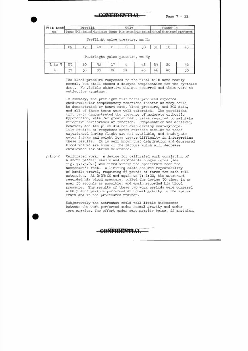
8/7/2019 Post Launch Memorandum Report for Mercury-Atlas No. 9(MA-9). Part 1 Mission Analysis
http://slidepdf.com/reader/full/post-launch-memorandum-report-for-mercury-atlas-no-9ma-9-part-1-mission 182/344
Page 7-21
Tilt test
no.
PretiltMean I Minimum I Maximum
Tilt
Mean I Minimum
Preflight pulse
29 17 4o _ 21
Postflight pulse
1 to 3
4
25
37
10
36
38
38
17
26
Maximum
Posttilt
Meanl Minimuml Maximum
pressure, mm Hg
6 58 31
pressure, mm Hg
6
14
42
46
29
46
10
20
40
46
36
50
7.1.5.2
The blood pressure responses to the final tilt were nearly
normal, but still showed a delayed compensation for the systolic
drop. Wo visible objective changes occurred and there were no
subjective symptoms.
In summary, the preflight tilt tests produced expected
cardiovascular compensatory reactions insofar as they could
be demonstrated by heart rate, blood pressure, and EGG data,
and all of these tests were well tolerated. The postflight
tilt tests demonstrated the presence of moderate orthostic
hypotension, with far greater heart rates required to maintain
effective cardiovascular function. Compensation was achieved,
however, and the pilot did not even develop near-syncope.
Tilt studies of responses after stresses similar to those
experienced during flight are not available, and inadequate
water intake and weight loss create difficulty in interpretingthese results. It is well known that dehydration and decreased
blood volume are some of the factors which will decrease
cardiovascular stress tolerance.
Calibrated work: A device for calibrated work consisting of
a short plastic handle and expandable bungee cords(see
fig. 7-1-5-2-1) was fixed within the spacecraft near the
astronaut's feet. A limiting cable ensured repeatability
of handle travel, requiring 65 pounds of force for each full
extension. At 2:25:00 and again at 7:4l:00, the astronaut
recorded his blood pressure, pulled the device 30 times in as
near 30 seconds as possible, and again recorded his blood
pressure. The results of these two work periods were compared
with 5 such periods performed at normal gravity in the space-
craft and in the procedures trainer.
Subjectively the astronaut could tell little difference
between the work performed under normal gravity and under
zero gravity, the effort under zero gravity being, if anything,
C O N F I D E N T I A L
8/7/2019 Post Launch Memorandum Report for Mercury-Atlas No. 9(MA-9). Part 1 Mission Analysis
http://slidepdf.com/reader/full/post-launch-memorandum-report-for-mercury-atlas-no-9ma-9-part-1-mission 183/344
slightly easier. During flight he felt his post-workbreathing was not as labored and he thought his heart rate
returned to pre-work values more rapidly. The data aresomewhat, affected by the difficulty he had in freeing thework handle from its restraining clip during flight.
Analysis of the data does not show any striking differencesbetween the one gravity and zero gravity work periods.Inflight mean heart rates during the calibrated work periodare 2.6 beats per minute higher than preflight, but hisinflight mean heart rate before work is 15 beats per minute-
higher; therefore this difference is not though to ~vbe significant,
The results are given in table 7-1-3-1-1 and presentedgraphically in figure 7-1-5.2-2. One preflight heart rateduring work was l6o beats per minute. This value occurredat the only time in one of the seven periods that he workedover 0.7 minute and probably reflects the prolongation of
the work period rather than indicating a higher work load.During the 18-second recovery period after the test, thepreflight mean heart rate is seen to drop to 11 beats perminute over the preflight value, while during the flight itfalls to 17 beats per minute over the prework mean. Thisdifference is also not thought to be significant. Bloodpressure readings taken before and after work show nosignificant changes from baseline values.
In summary, based on the inadequate evidence obtained duringthe MA-9mission, it appears that for brief periods of workfollowing relatively short periods of zero gravity, the
cardiovascular system shows no significant changes in heartrate or blood pressure. Subjectively,.calibrated workunder zero gravity seems easier, as do most tasks requiringphysical effort.
7.1.5.3 Special clinical studies: Retinal photography, urine andplasma electrolyte determinations, and plasma enzyme studiescomprise the special clinical studies. The retinal photographs,taken after the flight for comparison with preflight pictures,are not ready at the present time. The preliminary resultsof the plasma electrolyte determinations are available
and appear in table 7-1'5-3-1- If the increase in serum
calcium is valid, it is a small change. The results of theurine-electrolyte determination are presented in table 7.1.2.1-5;
however, the plasma-enzyme determinations are not yet available.
7-1.6 Conclusions.-1. There was no evidence of significant degradation of
pilot function directly attributable to the space flight.Thirty-four hours of zero gravity were well tolerated andall body functions appeared unaffected during flight.
8/7/2019 Post Launch Memorandum Report for Mercury-Atlas No. 9(MA-9). Part 1 Mission Analysis
http://slidepdf.com/reader/full/post-launch-memorandum-report-for-mercury-atlas-no-9ma-9-part-1-mission 184/344
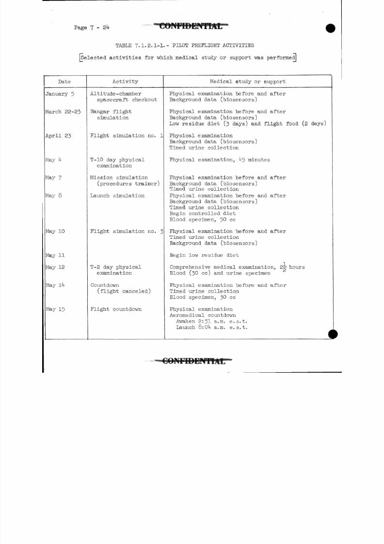
8/7/2019 Post Launch Memorandum Report for Mercury-Atlas No. 9(MA-9). Part 1 Mission Analysis
http://slidepdf.com/reader/full/post-launch-memorandum-report-for-mercury-atlas-no-9ma-9-part-1-mission 185/344
Page 7-24
TABLE 7.1.2.1-1.- PILOT PREFLIGHT ACTIVITIES
[Selected activities for which medical study or support was performed!
Date Activity Medical study or support
5
22-23
23
7
8
10
11
12
15
Altitude-chamber
spacecraft checkout
Hangar flight
simulation
Flight simulation no. 1
T-10 day physical
examination
Mission simulation
(procedures trainer)
Launch simulation
Flight simulation no. 3
T-2 day physical
examination
Countdown(flight canceled)
Flight countdown
Physical examination before and after
Background data (biosensors)
Physical examination before and after
Background data (biosensors)
Low residue diet (3 days) and flight food (2 days)
Physical examination
Background data (biosensors)Timed urine collection
Physical examination, ^5 minutes
Physical examination before and after
Background data (biosensors)
Timed urine collection
Physical examination before and after
Background data (biosensors)
Timed urine collection
Begin controlled dietBlood specimen, 50 cc
Physical examination before and after
Timed urine collection
Background data (biosensors)
Begin low residue diet
Comprehensive medical examination, 2 hours
Blood (30 cc) and urine specimen
Physical examination before and afterTimed urine collection
Blood specimen, 30 cc
Physical examination
Aeromedical countdown
Awaken 2:51 a.m. e.s.t.
Launch Q:0k a.m. e.s.t.
CONriDENTlAr
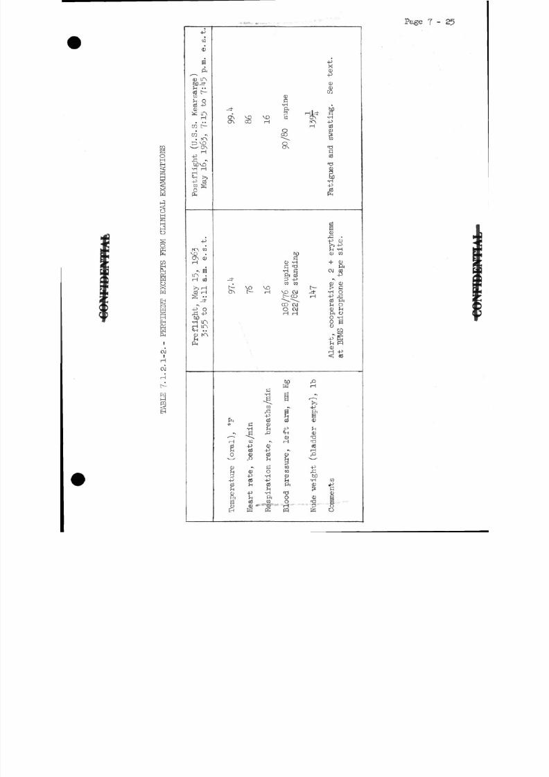
8/7/2019 Post Launch Memorandum Report for Mercury-Atlas No. 9(MA-9). Part 1 Mission Analysis
http://slidepdf.com/reader/full/post-launch-memorandum-report-for-mercury-atlas-no-9ma-9-part-1-mission 186/344
Page 7 - 2 5
oH
|
H
iJ
S
l-qO
S
C Q
S
OXH
EH
^
EHKWPH
OJ
H
O J
H
[4
-pco
CU
aPH
0 LAM-4-
03 L^-CO
S H O03 -P< L )W LA
1 1• • •
CO t-
C O - v
O NH
-pfi •>tiDVO•H HHM -t £>j
•P 03C O gO
PH
-P
rA coVO .O N 0H
^ 6L A «H 03
r-*} r 1
0 3 Hs • •
-4
-p" ofi -phO•H LAH LA
r
s•H"*• §*ON vo vo CQON oo H
/~ s
§.ON
hOa
a; -Hf l T J•H a
Pi 03-4- 2 -p
C Q C Q
L^ VO VOO N i^- H vo oj
t CO"*-* "'*-x^^
CO OJ0 OJHH
c•H
^C Q ~t~J g
-p SPH aJ o3o fl C D
•H H P*\ g rQ CH
' ^ - 0H co H0 3 -P 0^H 0 3 - PO 0 03 0
v O J j J_^
0 C CQ
fn 0 O CO^i -P -H 0
-P 05 -P ?H0 3 fn 03 Pi
d) -p -H T3ft !H PH Og 03 .CQ 0
0 0 • "• "C U HEH W K pq
-p
1
<U
CO
.
rPO N * HrA -PH 03
1
•O
0 3
r&
s54-*(jj
05CD
1>5 -P
?H "H0 CQ
+ 0Pi
OJ 03-p
»\
0 0D ^ S^-4 - -H OH -P &
0 3 Pi!M O
0) fnPi O0 -Ho aO
tfl0
<! 03
3»v
-pPi00
fH
0)'d•rio 3H
-£ •
g&D
•H co0 .P? a0r
r O
S O
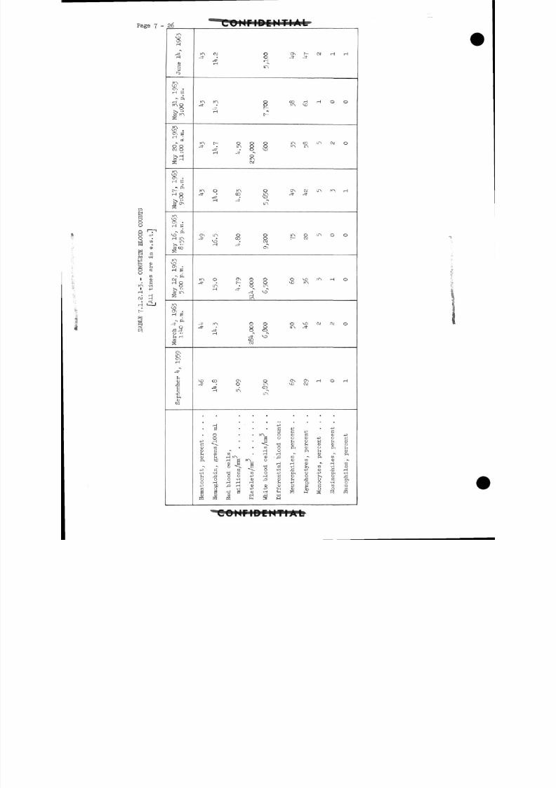
8/7/2019 Post Launch Memorandum Report for Mercury-Atlas No. 9(MA-9). Part 1 Mission Analysis
http://slidepdf.com/reader/full/post-launch-memorandum-report-for-mercury-atlas-no-9ma-9-part-1-mission 187/344
7 - 2 6
-H-P
KNVD
H
_ _ / *
H
CUc
KN
rH B'
- ft
rHKN OO
fe
C O
o oCM O
C C ? r Hs
VDON •rH S
- ftt-
H8
C O ON
S
$ -H S
vo" ft
rH inin
CO COS
KNVOON •
H e~ ft
CMH O
O
co in
VDON •
rH S
- ft
Ofi -=to ••fn HCO
ON
&rH
CU
HS-pftcu
CQ
KN OJ O
•* .* srH "»
ir\
KA K"\ O-3- • Oj-H
KN t O O O_= , in o o
-* oCM
KN O KN O_ = , • co in
in
O N in o o-=t • CO O
VD • CM
ON
KN O ON O O-=f t- O O
in o in
H
J- KN O OJ- • O 0
-=!• O COi 1 *> "*
coCM
VD CO ON O-* • o in
J- • COH in ^
S • • • c
O KN OO B o
-P H • • BC \ •<,•£)CD CO • CQ O
0 B HOrH CO CO H H
C D !-< H rn cu ,aft bD H g K\ o
C D B B H* * eg *\ B T^ co
-p S CO ^^ O -H•H -H TJ G to O -P;-, £> o o -p rH aO O O -H CD ,Q CUO H rH rH H !HHJ M P rH <U CU CU
CO O -H -P -P <HB B B £0 *H CHQ J < U C D 1 1 r "] -H
ffi W ffi FM 5 w
ON IV OJ H H-=!• -=t
CO H H O OKA M3
LA CO IT\ CV1 Oro \T\
O\ CM lf\ KN H
U"\ O LA O Or^ oj
O D N i rH O
O VO OJ OJ O
ON ON *H O r-1
VO OJ
-p • -pC -P CC D a < D - PCJ <D -P O £?H O C J H C DO £ H < U <D Oft Q J O ft h
ft ^H 0•N OJ f
CQ -\ ft CO
QJ CO CD *N
rH (D H CO
•H >i CO -H 0)
,U -P OJ Hft O -P ft -HO O !>i O ffto f\ 0 C ft-P ft O -H O3 S C to CQCU S O O m
•COHriDEHTIAL'
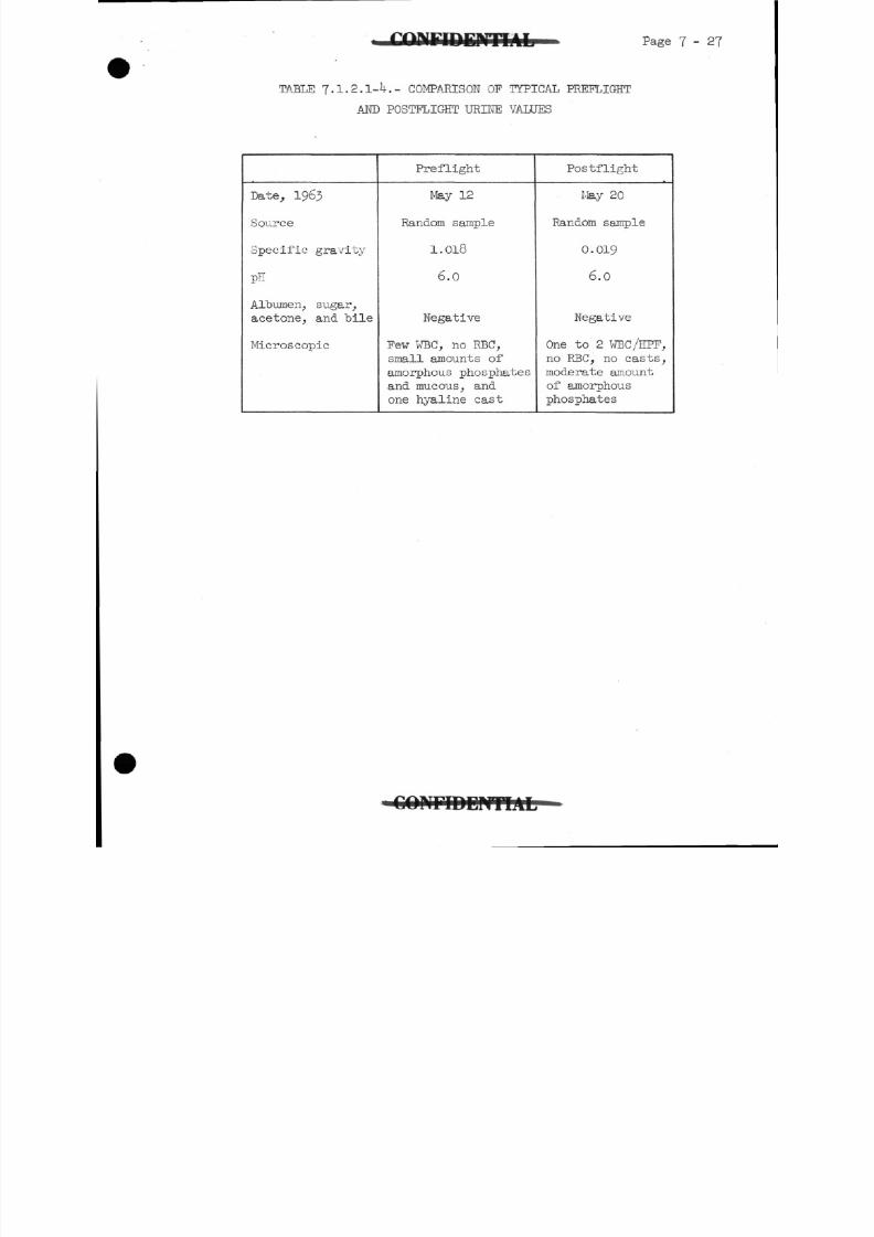
8/7/2019 Post Launch Memorandum Report for Mercury-Atlas No. 9(MA-9). Part 1 Mission Analysis
http://slidepdf.com/reader/full/post-launch-memorandum-report-for-mercury-atlas-no-9ma-9-part-1-mission 188/344
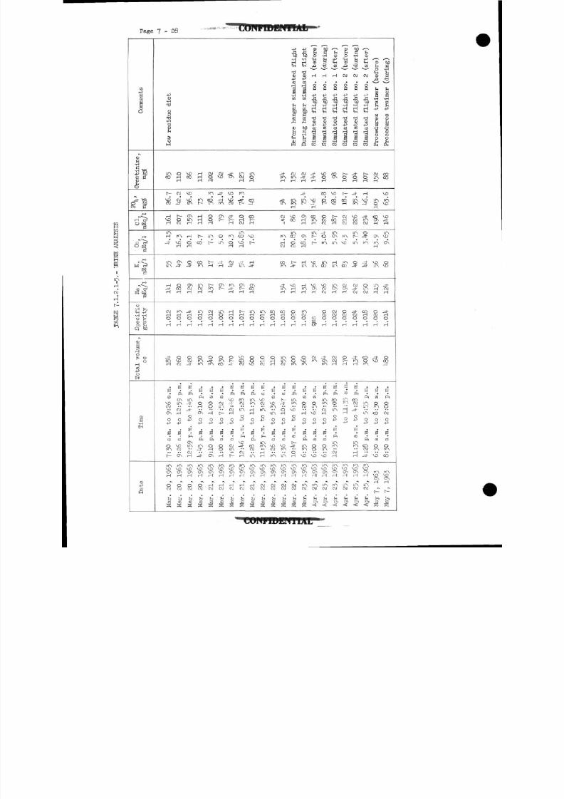
8/7/2019 Post Launch Memorandum Report for Mercury-Atlas No. 9(MA-9). Part 1 Mission Analysis
http://slidepdf.com/reader/full/post-launch-memorandum-report-for-mercury-atlas-no-9ma-9-part-1-mission 189/344
P ag e 7 - 2 8
Com
ments
Creatinine,
mg$
-=t >R
8 IPr-sH>OH
r-a
03 O1
OH
w"l?
ro
CC C^S W
O
t i • ?•H *H0 |>
ft rlK) Q
Total volume,
cc
n•HEH
-P
&
Low residue diet
inco
t-
VOOJ
H
^IAH
_z t -
lAin
rH-d"H
OJH0
H
J-
9
aC O
VO
ON
0-p
aC O
0rA
t
rA
»rH
OOJ
rl
£
aOJ
OJ-*
t-
8
rA
3
O NJ*
0
9
rAHO
rH
s(M
Bft
O Nin
OJrH
OHJ
BCD
VOOJ
ON
rA
*
H
OOJ
(H
VOCO
VO
ft
ON
S
M
S
0.3
O NOJH
-d-rHO
rH
0OJ
-3-
S
ft
inJt
_d-
O
-p
B'
ft
ONir\
H
rA
ttrH
OOJ
S-,
1
HHH
fAf-
dr-l
t-
CO
COMA
mOJrH
r?O
rH
RIA
eft
°
o\
O.p
0
ft
in-_ ^-
rA
>RH
0OJ
ri
CS
OJ
sfA
^R
O
S
in
t~-
&
t-tArH
OJH0
H
OJ-rA
e
co
§
H
O-p
0
ft
0rH
ON
hA
•-I
rHOJ
hC O
OJVD
_^
H
^
ONt-
oIA
^
ONt-
m8rH
fcCO
0
C O
OJ
[
OHJ
0
C3
8rH
rASOOSH
rHOJ
rl
C O
*VD
VDCV I
§
rA
S
OJ-=t
rAj-H
HrH0
rH
f
B
ft
vo_*
OJrH
O.-p
B
C O
OJ1A
t-
IAVOONrH
rH
OJ
rH
inOJH
tA
Jtt~
SOJ
inco
VDH
-=frin
ONtH
(H0
H
VOCOO J
0
ft
CO01
m
o-p
0
ft
VDJ-
rH
rAVDONH
HOJ
r)"
S
s
Svo
t^-
HJ-
ON
S
inHO
H
8VO
0
fi
inrA
rH
H
04J
0
ft
eoOJ
in
KN
1RH
HOJ
rl
S
inrHO
rH
SC \J
B
C O
VDOJ
rA
O
-P
0
ft
intA
H
rA
&H
OJOJ
h.-
soH
0HrH
B'
CO
VD
in
o-p
0
C O
VDOJ
IA
rA
&rH
OJOJ
r(CO
-*rAH
*
1
rA
d
^
j-mH
COrH
O
H
ininOJ
0
CD
t-=t
S
O+J
eC O
voIA
in
tAVOONrH
OJCV I
r(
03s
i•ri
dtj
^
Before hangar simule
OJinH
inrAH
VOco
inco
OCVI
t-=f
voHrH
80
H
8rr \
sPi
(T\K\
VD
0
•p
eCO
IF3K\VOCAH
C \Jcv
14C OS
4J
• a•H
ti•d
4^
3
•HW
rfl
1
1
MC•H
OJ_*H
-=r
P
O >HrH
O\
COH
rH
m
HK>H
rAOJ0
rH
sto
eCO
0
rH
O-p
sftinKA
VD
(AVDc\rH
tAOJ
ri
^
so
4nmP
rH
Simulated flight no
j-j-H
VD_d-H
ftrH
LfNt-
t
VOIA
«rH
ro
§
OJrA
B
CO
0
VO
o4J
B
C O
8VO
rAVOONH
(AOJ
1
12C
•H
&tj
H
Simulated flight no
«H
co
R .
oOJOJ
«rA
LA
CO
VOOJOJ
0OJ0
H
-ONrA
B'
ft
IArA
OJrH
O4J
B'
C O
0IA
VO
IAVD
S
rAOJ
ft<
rl
1CO
rH
Simulated flight no
«
vo
COvC
[--
SIAON
LA
HIA
L£ NONrH
OJOJ0
rH
OJ
3
B
ft
SLTN
0
•P
0
ft
inrA
H
KN
<H
rACV I
&<!
I
£<D
r
O J
Simulated flight no
1
r^
S
aOJ
rA
VD
IA00
&H
OOJorH
RrH
r;
CO
inIA
HrH
0-p
rAVC'o \rH
mOJ
rlPi
<
f -•60C•H
i-d
OJ
Simulated flight no
S
-4-
LAtA
VOOJOJ
LAt-
LA
O3
OJ-d-OJ
-3-OJ0
rH
_d-rAH
0
ft
COOJ
-=t
0
-p
B
CD
inrA
rH
rA
*
rH
inOJ
ft<
rl
CD
SCO
CV I
Simulated flight no
t
S
rH
VD.3
-*rACV I
o-d-
rA
_^-^3-
0inCVI
COrH0
H
SrA
0
ft
in
m
o-P
B
ft
ccOJ
J-
rA
'O NH
inOJ
1
C Drl
e0>r=
Procedures trainer
OJITSH
(AOrH
»H
O\
KNrH
voin
inrHrH
OOJo
rH
vS
eC O
o
CO
o-p
0
CD
0rrN
VO
rAvoON
t
!>»
1
MC
id
Procedures trainer
s
VD
rAVD
VO
aIAvoON
s
1
J-HO
H
O
S
0
ft
O
OJ
o•p
0
C O
orA
CO
rAVDON
r^-
!>,
i JT mmJrjbll 1JL/Uj
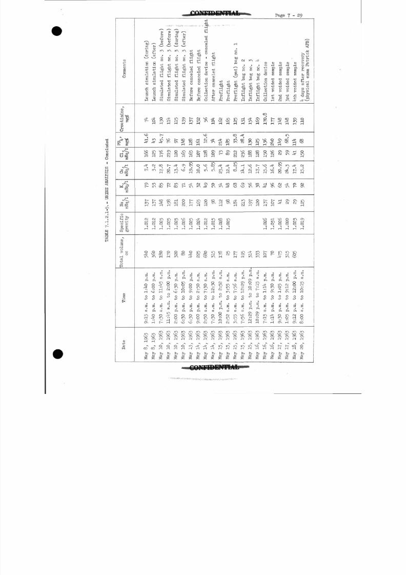
8/7/2019 Post Launch Memorandum Report for Mercury-Atlas No. 9(MA-9). Part 1 Mission Analysis
http://slidepdf.com/reader/full/post-launch-memorandum-report-for-mercury-atlas-no-9ma-9-part-1-mission 190/344
Page 7-29
Co
mments
-\
IC tR•H W
1
p hp
r-s
° ^
r-a
C O O1
1
"1ro
CO &
O
•H -H
o !>f t ^C D bO
I
O> 0
orH
CO-PO
EH
•HEH
<D
cp
'to
•H
Co•H
ie•H
C O
fi0
3
_ _ , .
VO
%^t
O Nc
rtAH
OJH
OH
SLA
S
ft
SrH
O
-P
B
C O
LAH
ON
KNVDONH
CO
C Os
< u
a
B•H-p
S•H
C Q
|
1
^
S
LA
rH
OJ
rA
rALA
t-
S
OJH
OH
IA
0
ft
8VD
O
•P
eft
SrH
IAVDONH
co
1
Simulated flight no. 3 (before)
orA
LA-=) -
VD
CO
rH
LACO
CO
fl
IAO J
OH
8rH
s'C O
LA
r-i
H
O
-P
S
C O
rA
t
IA
H
9
1
C Drl
£
CD
IA
Oc-p
•H
id
?•HCQ
_
£
ON
cl
t-
OJ
OJ
H
IAOJ
0rH
O
r7
B
Pi
OO
OJ
o-p
LAJ-
l-l
IAVOONH
3
C O
bOG•H
3
•2.
IA
OG
-p
•H
TJCD-P
C O
1•H09
LA
*
§
J.
IArH
IACO
HCOH
IAOJ
0rH
rA
S
ft
vo
o
B
ft
801
IA
rH
rH
SC OS
Simulated flight no. 3 (after)
ON
1
LA
ON
VD
11
OOOJ
VDOJ
0H
OCO
sftLA0
9o
-pB
Pi
VD
rA
ON
H
95?
Before canceled flight
c-
M
C O
rH
LAVOH
ON
ON
-4-LA
tt-H
LAOJ
0
H
0
s'ft
00
ON
o
B
ft
vo
IA
H
rAH
Before canceled flight
OJLA
H
H
t
3
O
9
OJrA
LAVOrH
-4-
8rH
LAOJC\J
S
C O
OJ
o
-pS
ft
O0
ON
IAVOONrH
.*rH
Collection d
evice - canceled flight
VDLA
vo
s i
1VD
LA
ON
0OJH
OJH
0
H
OCOVD
s'C O
o
t
o
B
C O
£O J
KN•ONH
rH
C?
After canceled flight
rA
ON
IAco
IA
LA
C OON
rH
O
rH
IArH
s'ft
RcurH
OH-J
B
C O
Rt-
voONH
rH
j?reflight
CV IV£)
1
P
t
OJ
A
rH
rH
co
8rH
H
s'C O
OJLA
OJ
o-p
oo
rH
rAD
rH
H
5?
Preflight
LA
S
LA
ONCO
J.
OJ
CO
ON
LTN
H
LTNO J
B'C O
LA
O
B
C O
O JLA
O J
\oON
H
LAH
rH
OC
bOc
id
&
•H
d1
LA
a
CO
OJ
LA01
co
S
s
ttrH
B
C O
voLA
0
-pB
co
LALA
rA
rH
H
OJ
6C
boC O
-p
so•H
8
H
sVD
OJ
H
H
C TNVO
OJ
LAON
rH
g
(iONOJ
OJrH
O
-p
B
C O
VO
t
rA\&ON
rH
LAi-H
S
Inflight hag no. 3
LA
r7
§
VD
0rH
VO
& ;rH
rH
B
ft
O
9O•P
ONOJ
H
VD(j\
rH
LAH
Inflight bag
no. 14-
VD
r?
S
t
H
R
S
R
B
C O
LAH
t-
o-p
ONO
H
'&H
VDrH
1
Collection d
evice
CO
H
OLAH
VD
LfNH
H
C
H
VOCVI
0rH
t
S
S
ft
rH
H
O
•p
eC O
c-
IAVDONrH
voH
<UH
C OCQ
> dCD
C OrH
O
«vo
rH
J-
VDrH
*IoH
H
0
H
Ot--
B
ft
R
o
B
ft
3
rH
VOONrH
voH
1
2nd voided s
ample
S
H
ONC U
LAON
OJ
OJ
rH
VOOJ
0
H
LAC -
B
ft
tA0
H
O
-p
B
ft
O
ON
VOONrH
I
H
<UrH
CO
CO
njCD
•H
id
rA
S
LA
S
ONA
fA
*
N
ONOJ
8H
LAH
B
ft
OJrH
C5 N
O
-P
B
Pi
IAO
H
IAVDCrH
rH
1
CDrH
C O
CQ
3•HO
^
Jf
j
_H-
rT
Ot
ONcy
SrH
LA
S
eftoo
O JH
O
•P
B
PH
O JrH
ON
IA
rH
S
k days after
recovery
(physical ex
am Patrick AKB)
S
s
&OJ
LAH
S N
LAO JH
ONrH
OH
B
CO
LArH
OrH
O
•P
B
CO
Oo
CO
rAVDONH
OOJ
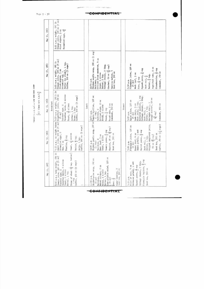
8/7/2019 Post Launch Memorandum Report for Mercury-Atlas No. 9(MA-9). Part 1 Mission Analysis
http://slidepdf.com/reader/full/post-launch-memorandum-report-for-mercury-atlas-no-9ma-9-part-1-mission 191/344
PaGe 7 - 30 COHMPEUTIAL
rA
3
H1
*
$H
H
1
rAVDONH
rAH
i
K-\VO
VDONrH
H
^
•pWCS
C OCUSM
-O OH
£• V->»
Jf
H 0O
* «H|OJ-POO H
•H COQ J * * MJ* QJ C OS
C J O QJ«»\ 'H £1). 3 5} TJ
H "TQ OJ. S H
OJ CO H )H
" r? 'H ft
^N
P O •
Jf §Cg^ -P W
HO H &y y
*• N •*4 0 O o ' ' toA OJ H M*~*13)H IT\ B•rf •* 4) y
C J O CD O• •. -H d fl VD. p 60 TJ o rAB "-3 -H C iJ * '. B H *
d] QJ rO ^ QJfib -P 5 <U 4>
LA. fi 4J CO -P $H
i* JH -H O 3 O
L A O C O. O QJ •*
t o co- - O
-H ft
H CM H 2H to 0
+T - OJ rAf\ OJ co ^ -bQ O OJ - QJ•H-H dO- O
QJ P' * O -H ft . O
>-<-D CO O H CO
bO cd co -P co O• •> _ p b O P - P VO. -H QJ H] CM H rA
g p" - C H H
CU rd t -P OJ >s QJ
O ft -31
O cd co -p QJ tin
t ^ O S o B ^ S o
Q J NX Ocd ^-P -=f CO
,G 0 CJbD o•H OJ rA<1 J O co •*--'> OJ - QJ
H CO ft O . O
flO
t-1
O bO p" -H ft . o£ -> M O H CO ft
O J QJ CO -p W O"* 0 H|CM -PVO. 'H T3 N i lloji 1 1 OJ rA
g 3 QJ O "> H H. -1-3H to *. ^
Cd t& VO CD *v FH "- QJQ J S ^! +J QJ J>, QJ
L A H c o ^ O C O -PH'fH
••ftuS CU O QJO
H ~CU
-4" N -PHO 3
co p*.-=!- QJ *~*
-p" 0 . COrC l -H ft ftbD O H co p•H O CO -p O
QJ> O OJ HlOJ fA
OJ ^ '>5 H OJ -N COTJ C QJ . 4-5 OO ^ - o o f t c d o
rQ QJ 10 O 'H CO CUo bD cd H -P ,c3 O
••, iH bD ^> co VO. p CD H rA
S -<-3 C OJ "+HT Cd - O ft **
O c d o c d c o - p S q_,
• • O O c d O 3 ^ O
H
7 SO
H ^ ft '
•» «S rQ P*
ft jj -P O
o a C M H|OJ-*w 3 ^ y
a n » » • y^ 0 • A) O 10H ^ y f t c o y CO'O w 'H W D Q J VOO O J a j H - P Q J O <wrA
• g -P w fl VD 8B d ^ w O J C J S ^
• w PO •* rtP Hf lC UfO »\4>- p C d C U
• I'HH'HaJ^J+s (1J QQJ
36^^(^(13 S Ifl
oo
0
H1 §
-v OJ NOd co o oo ^ cuH X 0 OJ OH cd
-H ft VO
•H OJC1J H 3 *. rA. P -P CO O QJ
S O *""•* * CO ^4 *•
, ,0 ft CQ oj H|OJrocu
o o £ cu *- *. cdlA-P -HHTJ CO T^C-J'CdH-PHciJ £-t dO.. 0 - H - H O J cd PS
O J O nJ f nS - i Q J O O J
Ooo
H *
& & °O o rAl-3"CO " CJ
N H|OJ 0CU O CU CJ
H CJ *v O OT3 fA 'H QJ VOO CM H CU O fAO - co fj ON
ft co cd H ft * cdft C P Q J O - P Q J
Q J O C H - O O -PLTN X -H -P -P ,Q-^tOH-P-PW c d ^ H T J.. -H *• • i I nj cd S 1* flJ
OJrCl C d Q J O Or i CJ
HO CQSIEH EH CO H
CJo oo
00 OJ
H
• ^ O1
^ft cdP OJ H CM Oo to cd cjCO -> OJ . CO
d o ft coodJ CU *H CO C3 Q J OO CM H -P -H -H rA
. -H O M +J ^
. I • * co ^2 rA H *~-* O cdftCNQJU - Q J t s l H|OJO QJ
C U O d ^^ibDO - P
.. -H H ^ QJ -P S " CtJ UO CU•j,c! cd d ^p - H QJ p^oHO CO" PQ PQ 'PQ 4-3 1**
1?*£$• CO H
Q JCC!•HQ
aQ N
& ° &
o O J ya ? N H^ ».H|oj y
•H ^ ft ,Jd •• OP rA cu HlOJ w co w co
"- D & U - P C 0 H^ p 5 •* -H
.0) $j O p HHlOJ"? h ••
ft|S3Hfl8 C§| 1
O Q J J - - P QJ ffl'tf-P CD CO O
v o S ^Mra^^l S
O 10 O£i O
0 H -P0 . O
ft -H HONO N CO CO OO J O - P ( L ) ^ -s-s oH HO - H -P
I T N H T J t Q ftHdJ O*. O O J H c o Q J ^ i VO
Q J * •*• O <D - P r ^ S n rA'O CO^C^J- C O Q J
,-H ftH OHH ^ -
£ |3 ' •• Qi l1
^ i 1 Q J W f t QJ
ft o o '"~3 ^ b O ^ n P H b O O J cj cdQ J O J cd QJ S &D C
- ^Sfio WS &
o o wH g,
O QJ OOJ S ft '!-3
H CU ^J H CMSO >> H
•> N ^H Ov
< D OH H[OJ h ' CJO . QJ ft O•H -s *, ft.Qp-00P ' O Q J H C O f t O V D" - 3 - N - P C U -pco r AO
CH cd ^-j ^ crj CMltA CO.0 QJ-Pp H H ^ - i ^ - --H£H'--aJO ftH^ cd
f t f t O 4 J ^ , ^ d J C J - P 003 - P f o O Q J ft <L >
O C - cdX ^H ^- i -P -HC O Q J C H
t ^ 2 f g ^ o ^ S g f i 3
r ft O
< U C OE ,Q OJ rA
IS1 ft +J
0 H 3 -o oj cd
-* - , 00O H CM -• O O
-, +3 dJ -HQ J (fi - CO ft OH -P QJ dJ Cd VOO O OJ QJ -P rAW ft FH fi
P 0 QJ -S CH J ft H CO. O QJ dJ ft d)
ft !H f!, bD ft +3-P QJ co cd d
LA cu -P cd -p cu tJH H -P P -P C! QJ. . T-H;3 CT1O 'H O[ fo FQ CO O CL, H
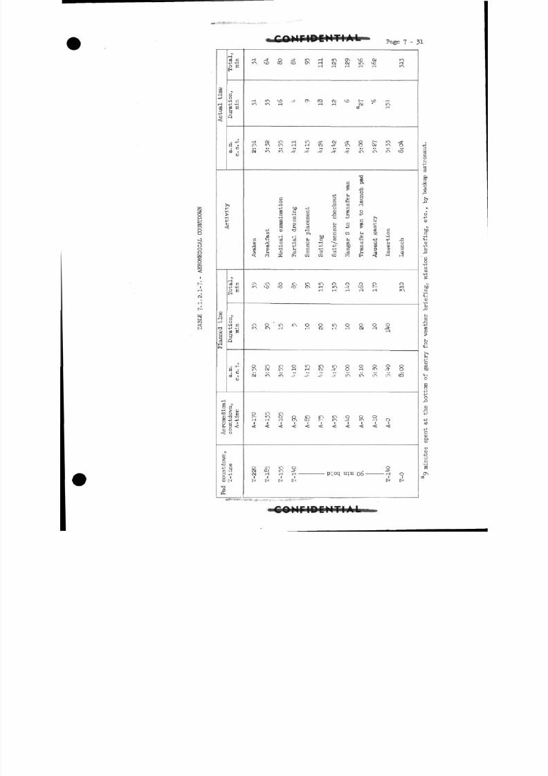
8/7/2019 Post Launch Memorandum Report for Mercury-Atlas No. 9(MA-9). Part 1 Mission Analysis
http://slidepdf.com/reader/full/post-launch-memorandum-report-for-mercury-atlas-no-9ma-9-part-1-mission 192/344
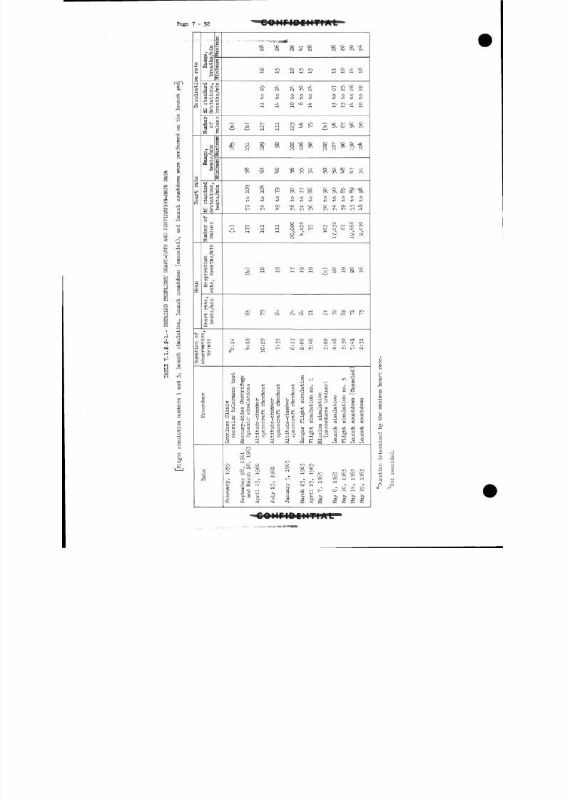
8/7/2019 Post Launch Memorandum Report for Mercury-Atlas No. 9(MA-9). Part 1 Mission Analysis
http://slidepdf.com/reader/full/post-launch-memorandum-report-for-mercury-atlas-no-9ma-9-part-1-mission 193/344
Page 7-32 COIiriBCMTI*L
<M
OJ
O
•a
ou
.C
8
R
espirati(
31p
fl$
a
<H
0
Duratic
a•H
Rang
breaths
±2 standard
deviations,
Number
of
a--H
£P
K 'S
1
i2
standard
deviations,
Nurnber of
values
Respiration
rate, "breaths/min
Heart
rate,
"bea
ts/min
GoH CP -H
H H<D ,CDO
O
Procet
<u4-J
( S
><!
Minimum
"breaths/min
values
3
Minimum
"beats/min
C O ^D V£> H CO COU3OJ-O J O J O J - d - O J O J O J K N O J
OJ KN O KN KN H O -=J- OH H HHH HHHH
LA -d- -3- O -3- t LA VD OJO J O J O J K N O J O J O J O J O J
O O O O O O O O O-p -p -p. -p -p . p -p -p -p
H -3" O CO ^3" KN KN -3" OH H H H HHHH
'- - •- t H KN -=t IA * _=J- C SO O,0 p H H Oj -d~ t P ON VO ON IA- _x H H H
C O LA OJ ON O O O N O O ON K N OHHH HH HH HH
C O Q VD V Oi A H Q OJ CO C HIA ) -d" IM LA LA LA LA JO" -=J~LA
ON ^t-O O ON O j C VD O J Q I A O N C QH H c O N D - - C O O N O N C O C O O N
O O O O O O O O O O O-p -p -p -P-P-P - p - p - p - p - p
L^ -^ ON *^0 H *^O O -3" ON KN CO
LA LA J" in IA LA LA U~N KN in -it
§ J- OJ VD OLfN LA KN KN L VO H
,Q t ^D H OOJC^ O O J M 3 ^ £ ) O
S -=t £~ ON ONH H
p H H HHH P O J H O J H
KN ON J- ^ - _ ^ - H H O J OJ H K N
CO t VO C MD C t t V£l t-- b-
J- CO ON KN t OO O J C O OH HH H OJ KN HO -= f O J - ^ t K N - J - K N
o J- o f V O O J K N L A J - K N L A O J03 H
-P O JW 0 G H(U & OH KN (U+J J3 -H • - O
< H W -p -p + > 4 J . ^ -GQ J - H G " 3 3 3 o J O C D O c dOh O O O O H G G G ^ ,
c c 3 r t - p o o u S d o c f l S Rfn 0 > n J f n C L l fnl) f - i < U - H O - H H O O G G
• H H ' ppcjpupo -P03- P - P O O
•H-P OJ'H S+J B4^ 2^ '
C^ '7J^
l l >' ~
lr J"
f"
> 4"
>
w < ; o I^H I^H i fi H «Hw - d - H - 3 o o
H ON
H »v KNON CO OJ M3 rO KN(A ->OJ VD OJ ON MD VDO N C O O N V O H O N O N K N K N K NH OJJ^H ON H H K N KNSO^1^
O H •* V i ) V D O N O N O N* ^ , ^ 1 ^ i r \ - \ ^ ONO N H H H^ Qj'Jfi KN *> KN KN H HM pd S H KN r*> OJ OJ *• •» *
N
P OJ 'O H rG H t - CO HHH^ • P C i H S P O - H
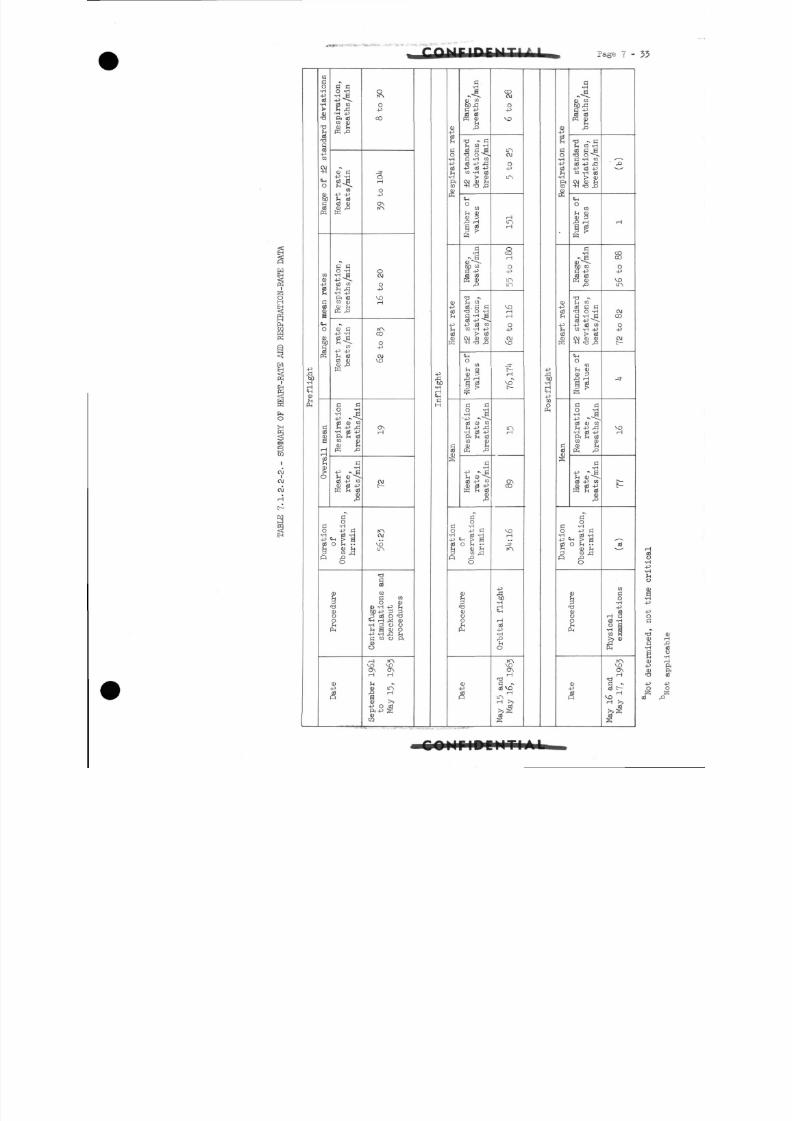
8/7/2019 Post Launch Memorandum Report for Mercury-Atlas No. 9(MA-9). Part 1 Mission Analysis
http://slidepdf.com/reader/full/post-launch-memorandum-report-for-mercury-atlas-no-9ma-9-part-1-mission 194/344
Page 7- 3 3
1
-pft60-H
ClCD
£
DDC0•H-P
.20)
TJ
rH
1
4JCO
$1
O
8)jH
K
CQ
CD
§
1
C|-j
0
CDtoc
1
Gc dE
rHH
2[>0
«.
G CO vH
uP fljCO 0)w H
K ,a
JU C
B'iCO
-p -prH Cdc d C DCD rP
G GO -H
C d C Q
•H £PH CdC O CDO J rHM P
^C D C-p -H
C Q
JH cdC O C DCU ,Q
G C0 -rj•H B-P -v
2 C D C O-p a
•H cd -P
PH rH CdC O C D
CD fiK £>
C•H
-P -cd - P c o
flfij
10 -PC•H Cd -H-p "H > aCd 0 rH • ••
R ,P *O
•aCDO
i
£H
Ol*>
0
CO
J.o
o-p
ONro
O
H
CO
O
OJ\D
ONH
OJ
KNOJ
voIn
•a
§
CO
O CD<t> Tl -P rH
M-P 3 3p 0 O tiM H H ^ CD•H 3 O CJh B CD O-P iH J3 hC CO o ftCDO
H N"Nvo voO\ ON
CD mP HSCD !>>
§
H
H
Q J-P
2CO•H_p
cd
rH•H
ftCO
&
CD
2-pticdjj
GC O
S
C•H
0) CO
K CDrH
rfl - C
rrt c P•a o<C -rt COc d - P J 3
-p cd -Pc o - H c d
C\| CLJ ST| T3 rP
IHO
C Orl CD
CD 3P rH
3 P
^
a•ri
"-§_W ) C QG -Pc o c O
rH CD
cd . G GT3 O -Ha -H acd -p^
- p c d C DC O -H 4J
CD CU
CHO
CQ
rH CU
CD P
'c d
&>
C GO -H
•4J *. ^c d c u C D
•H Cd -P
ft rH CdC Q C DCD rHK £>
G-H
- p * > acd - P c o
se|
oG 'HO -P G•H 0 -H
•PHH r* 3
Cd O rH ••
R f> **O
1CDCJO
CU-pSSR
CO
o-p
vo
O J
o
in
rHLTNH
rH
O-P
LTALTN
VOr-HH
O-P
OJ
H
iniH
ONCO
VOH
j-
-pi-HrH<H
Hcd-p•H
O
VOON
13
G -c d V O
i-iLTNH >>
fl
bb•H
!H
CO
OPH
-p
£
O-H
2•H
ftCO
QJK
0)-P
2-p
c d
Ccdflj
S
c•H
Q J C O
ffi nj
•0 GrH CO -H
r§Q G -H CO
0 -P f!•P 0 -P
CO -H 0
OJ CD S+1rrj f
<H
OCO
§ gK
g
aTM) COG -P0 0
PS C D
h CO0 G G
• s s - g0-P^-P 0 CQ
CO -H -p> cd
OJ CD CD+i Td »P
CHO
COrl CU
I*
•&:
G C
O TH
0 CD COri -P f•H 0 +3
PH S CdC O C D
CD rl
PS P
G•H
-P - SM CD^-^0 -P CO
AfiJ
G"
G 5O -p G•H 0 -H-P HH 5 g0 0 EH • •H 0) fH
3 co j3R f
O
i
•OCDCJ
1
CD-P
CO0
_ r ~ i^
H
COffl
O-p
VOm
OJ
o-p
C Mr-
-*
VOH
t-t-
0
C OGO•H-P
0 -H
C O S
PH
S
r -j
S -v
vorH >>
•aC Dc
c d
^^3
ftftc d
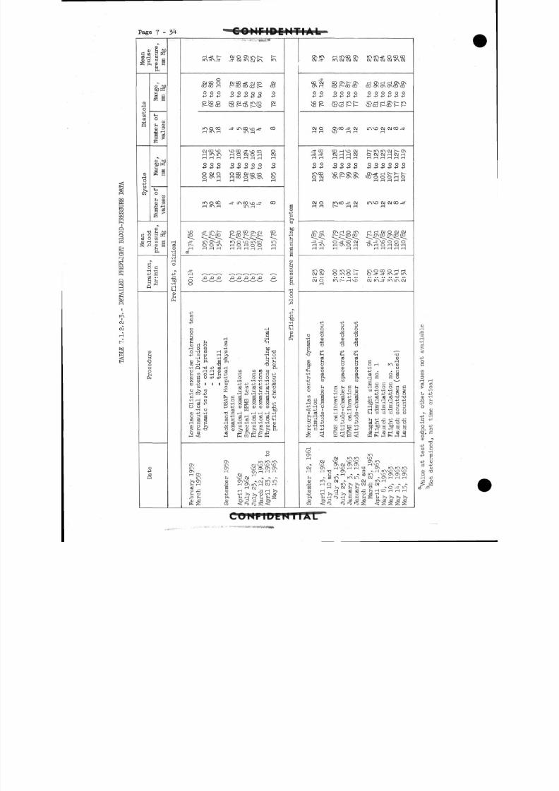
8/7/2019 Post Launch Memorandum Report for Mercury-Atlas No. 9(MA-9). Part 1 Mission Analysis
http://slidepdf.com/reader/full/post-launch-memorandum-report-for-mercury-atlas-no-9ma-9-part-1-mission 195/344
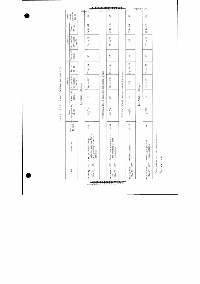
8/7/2019 Post Launch Memorandum Report for Mercury-Atlas No. 9(MA-9). Part 1 Mission Analysis
http://slidepdf.com/reader/full/post-launch-memorandum-report-for-mercury-atlas-no-9ma-9-part-1-mission 196/344
7 - 35
(!)
G CD P t)D
* % % *
CD
O
-pCQ
C O
S
<DHO-P
CO
CO
C D 606DKS3
K1t-H K
• g c-cd oT3 -H 60c -P a?c d c d-p -H E
CD
OCO
S3frH
i gte
CD hfl60 tn
c d aP S i
•2 S3~cd o
T3 -H 60S3 -p 33c d c d-p iH S
co i> g
-H
CHO
CO
f> H
£
^< u
§CO
co M
a CDK03 rH
s^ioH
0 C!•H -H•P £
p
JH
^
'SOgPH
CD-P
0
«V*
cdo•H
fl•H
u
-p
1•H
HCH
C D
P H
-.».,»,
-=f
SO
__ j
\D
ONCO
O-p
ON
LTNON
OJrH
Q
CO
CO
t
"o-p
ONON
in
ONt
toHH
•ji
CO
-p 11 C O - H
•H CD E
K H CD
-H -P
S 3 0 A30 CD 60
•H ft -H-P CO rH0 <H
C D ~ C D C OH C H S3
C D O ft OCO -H -H
4J Tj 4J
I s c d S 3 c dCD S3 Cd S3
o
ITSON VOLTN ONON rH
rH
>> LTN
JvH ' 1
cd3 S
§-PCO
CO
•H
CO
cfl0)S
g
to
Sftr J
O
OHrO
_p
60•H
CDS
PH
KN
CMrH
-P
rHVO
OON
o-p
"
orH
CO-=fH
0-P
ON
CO
H
O-P
\oco
-8rH
ONt
9 "H
ON
O
VOLTN
CO
S3
O -P•H CO
GJ -P
3 -P
•H 60
CO - H C OrH CDCD EH JH
ho CD 3P 13<H ft CD•H O
^ -d o-P S3 ^H
S 3 cd ftu
H KN
\C v oON ONH H
•HC D ir\
B
-§ 0
1
-P
to
•H
CO
03
S
g
CO
CO
Eft
r J
ooH
^] _ • >
60•HrHIH
S3H
CO
£
-p
POP-
j
O J
H
H
O-P
ONO
H
f ^^o
C M
rHCO
ONrHrH
VOrH
Jt
1 1
•g,
•H
drH
cd-p•H
-g
0
SrH
•O
S3 -v
cd vo
LTNrH >
rH
cdo•HS3•HHCJ
-pA3M•HH
-P
OPH
tTNCM
OJCO
O-p
CMLT N
P
O-P
LTNLTN
rH
0OrH
O
VO
CO
C--
orH
o-p
IAt
"H
vovo
Sv
cd
H
cd0
to>, m
• a s•H-P -P
•H -H
<H 3
tO C D
VOONH
S3 -vcf l t~-
VOrH -1
O•H
4•H
SH
-POC
•a0)
S3
O
K
cd
,0
cd
ftftCO
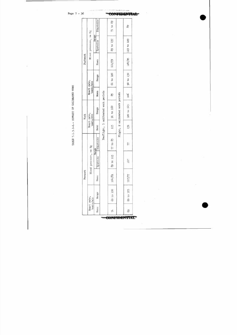
8/7/2019 Post Launch Memorandum Report for Mercury-Atlas No. 9(MA-9). Part 1 Mission Analysis
http://slidepdf.com/reader/full/post-launch-memorandum-report-for-mercury-atlas-no-9ma-9-part-1-mission 197/344
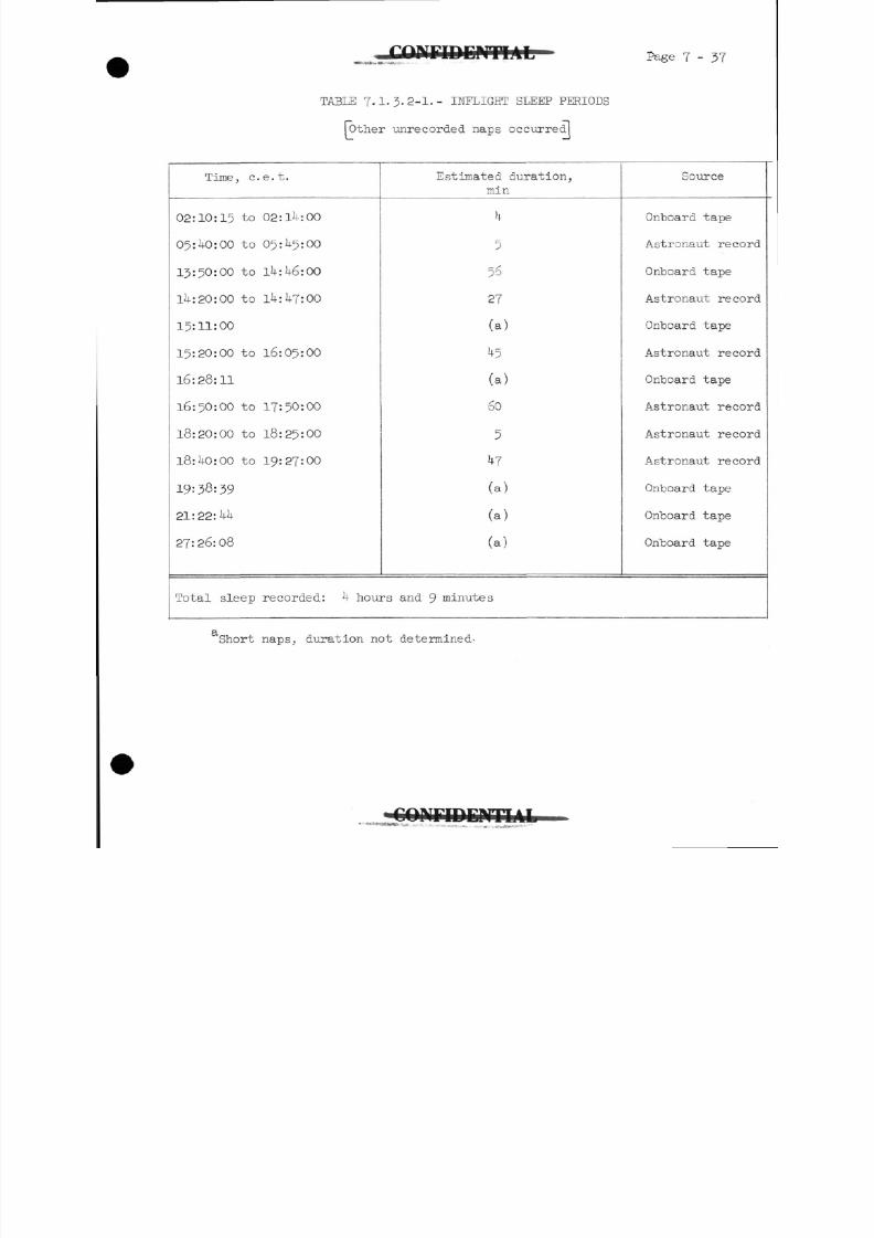
8/7/2019 Post Launch Memorandum Report for Mercury-Atlas No. 9(MA-9). Part 1 Mission Analysis
http://slidepdf.com/reader/full/post-launch-memorandum-report-for-mercury-atlas-no-9ma-9-part-1-mission 198/344
Page 7 - 37
TABLE 7.1.3-2-1.- INFLIGHT SLEEP PERIODS
[other unrecorded naps occurred!
Time, c.e.t.
02:10:15 to 02:11*: 00
05:1*0: 00 to 05: 5:00
13:50:00 to Ik:k6:00
Ik:20: 00 to lk:kj:00
15:11:00
15:20:00 to 16:05:00
16:28:11
16:50:00 to 17:50:00
18:20:00 to 18:25:00
18:1*0:00 to 19:27:00
19=38:39
21:22:kk
27:26:08
Estimated duration,
min
k
5
56
27
(a)
^5
(a)
60
5
7
(a)
(a)
(a)
Source
Onboard tape
Astronaut reco
Onboard tape
Astronaut reco
Onboard tape
Astronaut reco
Onboard tape
Astronaut reco
Astronaut reco
Astronaut reco
Onboard tape
Onboard tape
Onboard tape
Total sleep recorded: k hours and 9 minutes
Short naps, duration not determined-
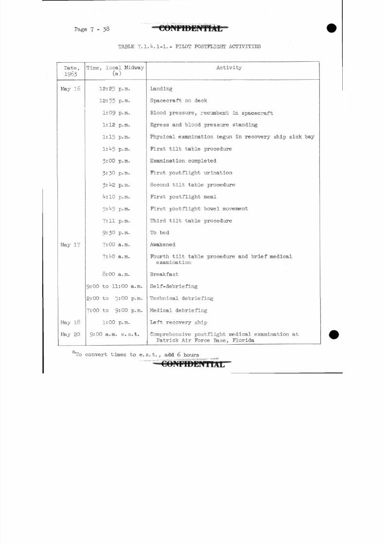
8/7/2019 Post Launch Memorandum Report for Mercury-Atlas No. 9(MA-9). Part 1 Mission Analysis
http://slidepdf.com/reader/full/post-launch-memorandum-report-for-mercury-atlas-no-9ma-9-part-1-mission 199/344
Page 7- 3 8 C O N F I D E N T I A L
TABLE 7.I.IK 1-1.- PILOT POSTFLIGHT ACTIVITIES
Date,
1963
Time, local Midway
(a)
Activity
May l6
May 17
May 18
May 20
12:25 P-m.
12:55 p.m.
1:09 p.m.
1:12 p.m.
1:15 p.m.
l:U5 p.m.
J:00 p.m.
3:30 p.m.
3:U2 p.m.
U:10 p.m.
5:^5 p.m.
7:11 p.m.
9:30 p.m.
7:00 a.m.
7:1+0 a.m.
8:00 a.m.
9:00 to 11:00 a.m.
2:00 to 5:00 p.m.
7:00 to 9:00 p.m.
1:00 p.m.
9:00 a.m. e. s. t.
Landing
Spacecraft on deck
Blood pressure, recumbent in spacecraft
Egress and blood pressure standing
Physical examination begun in recovery ship sick bay
First tilt table procedure
Examination completed
First postflight urination
Second tilt table procedure
First postflight meal
First postflight bowel movement
Third tilt table procedure
To bed
Awakened
Fourth tilt table procedure and brief medical
examination
Breakfast
Self-debriefing
Technical debriefing
Medical debriefing
Left recovery ship
Comprehensive postflight medical examination at
Patrick Air Force Base, Florida
To convert times to e.s.t., add 6 hours
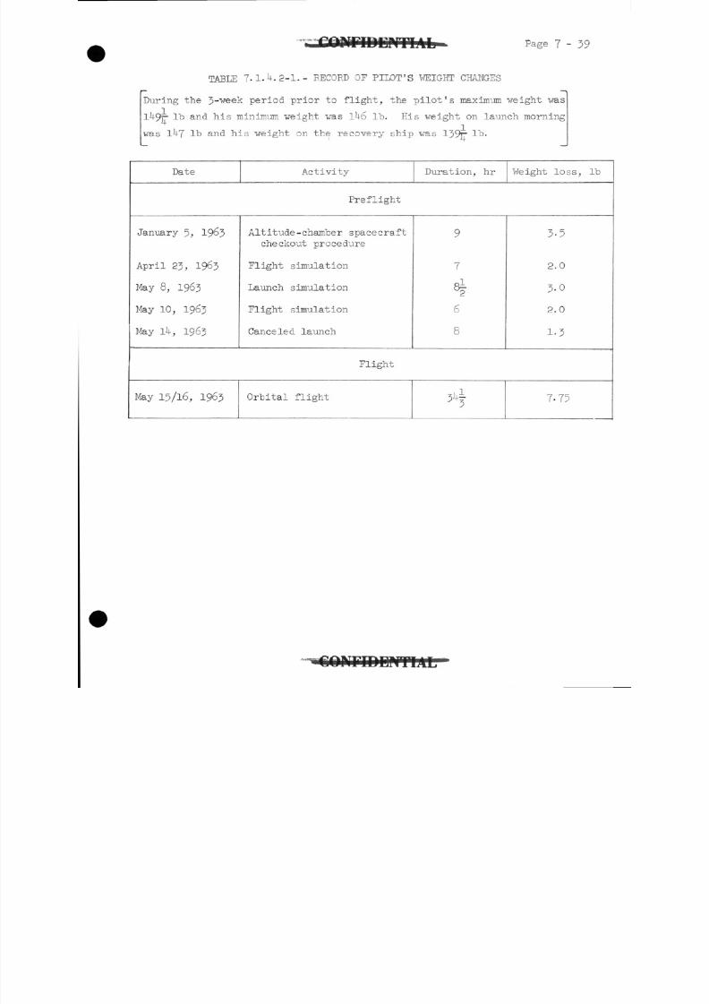
8/7/2019 Post Launch Memorandum Report for Mercury-Atlas No. 9(MA-9). Part 1 Mission Analysis
http://slidepdf.com/reader/full/post-launch-memorandum-report-for-mercury-atlas-no-9ma-9-part-1-mission 200/344
Page 7-39
TABLE 7.1. .2-1.- RECORD OF PILOT'S WEIGHT CHANGES
During the J-^eek period prior to flight, the pilot's maximum weight was
1 9r lb and his minimum weight was 1^6 l"b. His weight on launch morning
!
was 1 7 lb and his weight on the recovery ship was 139r It.
Date Activity Duration, hr Weight loss, lb
Pre flight
January 5, 19 3
April 23, 1963
May 8, 1963
May 10, 1963
May 14, 1963
Altitude -chamber spacecraft
checkout procedure
Flight simulation
Launch simulation
Flight simulation
Canceled launch
9
7
8|
6
8
3-5
2.0
3.0
2.0
1-3
Flight
May 15/16, 1963 Orbital flight ^ 7-75
C O M T D D F r i T A L
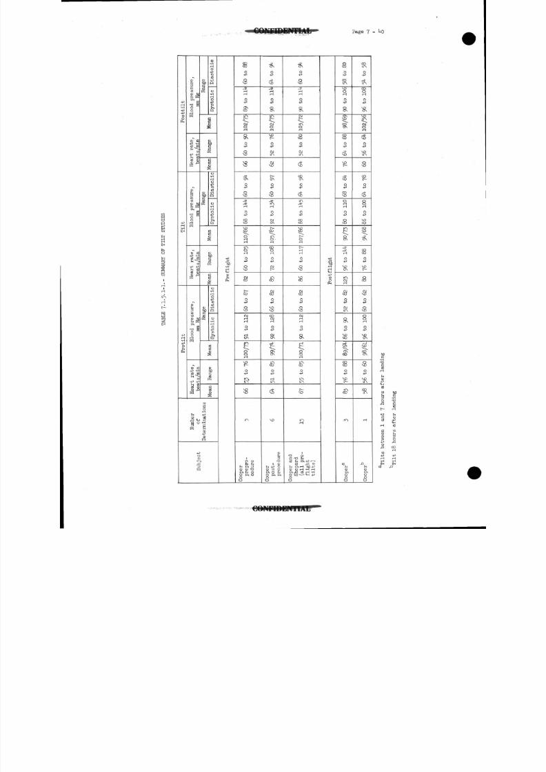
8/7/2019 Post Launch Memorandum Report for Mercury-Atlas No. 9(MA-9). Part 1 Mission Analysis
http://slidepdf.com/reader/full/post-launch-memorandum-report-for-mercury-atlas-no-9ma-9-part-1-mission 201/344
Page 7 - 1+0
-P +3
f n 0 3a
J!<H g
&O•P
8
CO
O
-p
SH
S K
oper
post-
proce
4)Hft -P -
O o H *ft ^J o3
p
COir\
0
s
1
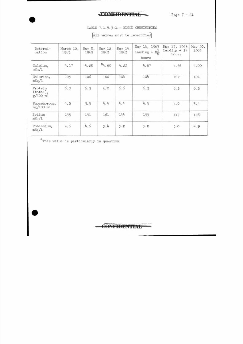
8/7/2019 Post Launch Memorandum Report for Mercury-Atlas No. 9(MA-9). Part 1 Mission Analysis
http://slidepdf.com/reader/full/post-launch-memorandum-report-for-mercury-atlas-no-9ma-9-part-1-mission 202/344
Page 7 - 4l
TABLE 7.1.5.3-1.- BLOOD CHEMISTRIES
JA11 "values must be reverified
Determi-
nation
ml
hosphorous,
ml
March 12,
1963
k.YI
105
6.0
4.2
153
k.6
May 8,
1963
4.28
106
6 - 3
3 - 5
151
4.6
May 12,
1963
al|.60
100
6.0
u . u
161
5.1*
May 1 ,
1963
U.22
104
6 .6
k . h
14U
5 - 2
May 16, 1963
landing + 2
hours
4.67
104
6 - 3
4.5
153
5 - 2
May 17, 1963
Landing + 24
hours
4.56
102
6.2
4.0
147
5-0
May 20,
1963
4.22
104
6.2
3-4
146
4.9
This value is particularly in question.
8/7/2019 Post Launch Memorandum Report for Mercury-Atlas No. 9(MA-9). Part 1 Mission Analysis
http://slidepdf.com/reader/full/post-launch-memorandum-report-for-mercury-atlas-no-9ma-9-part-1-mission 203/344
p a g e T - ^2 tJONFIDENTIAL
7.2 Pilot Performance
7.2.1 Preflight training.-
7.2.1.1 Spacecraft checkout activities: Intensive participation in
the preflight checkout activities enabled the pilot to be-come familiar with the MA-9 spacecraft and launch-vehicle
systems. Participation in these activities was particularly
important because the pilot had the opportunity to operate
and to become familiar with the characteristics of the modi-
fied systems and switching procedures peculiar to his own
spacecraft. Table 7*2.1.1-1 summarizes the checkout activi-
ties in which he spent 73 hours and 50 minutes in the space-
craft. This table does not include the many hours spent
by the pilot in preparation, troubleshooting, monitoring
tests as an outside observer, and posttest analysis. In
addition, as backup to Astronaut Schirra, the pilot spent
approximately ^0 hours in the MA-8 spacecraft, which addedto his knowledge of the Mercury spacecraft in general.
7.2.1.2 Flight simulation training activities: Table 7.2.1.2-1
summarizes the training activities on the Cape Canaveral
procedures trainer from March 15 to May 13, 1963* The pilot
spent 33 hours and 30 minutes on the trainer accomplishing
^3 turnaround maneuvers, 62 simulated manual retrofires,
8l simulated systems failures, and 28 manual reentries. In
addition, the pilot spent approximately 20 hours on thepro-
cedures trainer during the MA-8 preflight period.
The pilot spent the majority of his time during these sessions
on the detection and circumvention of simulated systems failures
and various mission anomalies which would require an abort
during the launch phase of the flight. The pilot concentrated
on these areas because of their critical importance and because
the procedures trainer is best equipped to simulate these
phases of the mission. He did,however, spend approximately
one-third of his time during these training sessions on the
normal flight activities specified in the flight plan and
practicing of retrofire and reentry attitude and rate control
maneuvers. The pilot also participated in several launch
abort and network simulations during which mission rules and
operational procedures were extensively used and reviewed.
7.2.1.3 Flying proficiency: Throughout the preflight training period,
the pilot continued to maintain flying proficiency in high-
performance aircraft. He logged 6k hours and 35 minutes in
flying time from January 1 to May 10, 1963 (see table 7.2.1.3-1),
Flying high-performance aircraft is an important complement to
the more direct space-flight preparation activities on the
static trainers, because it requires the pilot to maintain the
COMTDONTIAlr
8/7/2019 Post Launch Memorandum Report for Mercury-Atlas No. 9(MA-9). Part 1 Mission Analysis
http://slidepdf.com/reader/full/post-launch-memorandum-report-for-mercury-atlas-no-9ma-9-part-1-mission 204/344
Page
ability to make quick and accurate analyses and decisions under
actual operational conditions.
7.2.1.U Systems and operational briefings: The pilot received two
series of formal systems briefings which were oriented as
much as possible toward the operational requirements of themission. The first series of briefings required 3 days time
during which each spacecraft subsystem was extensively re-
viewed, while the second series required only 1 day since
its purpose was to review recent spacecraft systems
modifications.
The pilot received two series of briefings on inflight
experiments, each series requiring 1 day to complete. During
these presentations'1the experiment, its purpose, its associated
equipment, and the operational procedures were discussed, final-
ized, and integrated into the flight plan. In addition, the
pilot spent many more hours with various systems and operationspersonnel on an informal basis in order to establish optimal
operational procedures.
7.2.1.5 Preflight-operations schedule: Table 7-2.1.5-1 summarizes
the major activities in which the pilot was involved from
January 2, 1963, until launch. In addition to the large
amount of time spent in briefings, spacecraft checkout
activities, flying, and on the procedures trainers, the
pilot was also able to take part in several special training
activities. Among these activities were four sessions at the
Morehead Planetarium, during which he reviewed the celestial
sphere and participated in a simulation of the flashing light
experiment; acceleration refamiliarization in the Johnsville
centrifuge; and recovery and egress training and survival-
equipment exercises.
7-2.1.6 Training analysis: The pilot, like his predecessor, con-
centrated his major effort in learning the spacecraft' s
systems and their operational characteristics. The pilot
achieved a high level of skill on the procedures trainer
in coping with systems failures and operational anomalies.
Particular concentration was placed in developing proce-
dures for accomplishing inflight activities with a minimal
expenditure of onboard consumables. The pilot practiced
these activities on the trainers only after he knew each
system or operation extremely well and all spacecraft sys-
tem modifications had been completed.
He also obtained considerable practice in performing man-
ually such tasks as the turnaround, retrofire, and reentry
maneuvers by using the attitude and rate indicators. A good
understanding of the spacecraft's control systems was provided
C O N F I D E N T I A L
8/7/2019 Post Launch Memorandum Report for Mercury-Atlas No. 9(MA-9). Part 1 Mission Analysis
http://slidepdf.com/reader/full/post-launch-memorandum-report-for-mercury-atlas-no-9ma-9-part-1-mission 205/344
p a g e 7 - * C O N F I D E N T I A L
through systems briefing and the use of the transparent
gyro simulatior; and the yaw-recognition trainer helped
him to prepare for those inflight activities, such as
gyro realinement and- flight maneuvering with the use of
external references, that are not properly simulated on
the Cape Canaveral procedures trainer. The pilot reportedthat the'one inflight experience for which he was not well
prepared was the out-the-window view. Since this view can-
not be easily simulated, it was a novel experience to the
pilot and did cause him some distraction, but i t was not
a major problem.
Because of experience gained from past Mercury flights, a
fairly long preflight period, and a diligent and intensive
training program, the pilot reported, and the results verify,
that>he was very well prepared for this flight. He reported
that, in general, there was a proper proportion of training
effort placed upon the different aspects of his mission. The
only significant areas of pilot preflight preparation that the
pilot believed could be improved or supplemented were:
1. An earlier finalization of systems and attendant
operational procedures
2. Additional improved external-reference simulations
3- Additional training on the recognition and observa-
tion of celestial bodies
k. Less egress training through the top hatch
5. Somewhat more concentration on normal as opposed
to emergency procedures during the simulation of the launch
phase of the mission on the procedures trainer
7.2.2 Flight-plan activities.-
7-2.2.1 Flight-plan description and results: The flight plan was
designed so that the operational test requirements and
approved experiments could be accomplished within a 22-pass
mission. The duration of the mission required the scheduling
of an 8-hour sleep-rest period.
The mission was separated into four phases with go-no-go
decisions at the end of the 1st, 7"th,and l6th orbital passes.
In order to conserve consumables and still accomplish all of
the operational and experimental objectives, the pilot was
to refrain from using the automatic stabilization and control
system (ASCS) bus and allow the spacecraft to drift for long
periods of time. The turnaround maneuver was scheduled to be
8/7/2019 Post Launch Memorandum Report for Mercury-Atlas No. 9(MA-9). Part 1 Mission Analysis
http://slidepdf.com/reader/full/post-launch-memorandum-report-for-mercury-atlas-no-9ma-9-part-1-mission 206/344
Page 7 -
accomplished manually by the pilot; however, the retrofireand reentry events were to be controlled by the automaticcontrol system.
The pilot's adherence to the flight plan was excellent, andalmost all of the flight activities were completed as planned.
Table 7.2.2.1-1 presents a summary of the major events thatoccurred during the flight. Up to the time at which a fail-ure involving the automatic stabilization and control system0.05g relay circuit and the subsequent loss of all ASCSa-c power occurred, all of the major planned events wereaccomplished at approximately the programed times. Thereafter,the pilot concentrated primarily on checking out the status ofsystems and isolating the malfunctions that had occurred. How-ever, he still managed to complete most of the flight-planactivities that were scheduled after the malfunctions werenoted.
The first phase of the mission was accomplished as planned andall systems were thoroughly checked out with the exception ofthe fly-by-wire (PBW)high thrusters. A decision was made toproceed into the second phase of the mission at the end of the1st orbital pass.
The second phase was accomplished as planned. The flashinglight was deployed at 3:25:38 and shortly thereafter theASCS a-c bus was powered down. Although the pilot did notobserve the flashing beacon during the first night phaseafter deployment, he was able to make several observations
during the next two night phases. The telemetry mode ofthe TV transmitter was checked over Hawaii and Californiaduring the 3^1 orbital pass, and the pilot sent continuous-wave code signals to Bermuda during the ^th orbital pass.At 6:22:00, the pilot turned the cabin fan and cabin-coolantflow off, powered up the ASCS a-c bus, and returned the space-craft to ASCS control. At about 8:21:00, the pilot returnedto FBW-low and pitched down for observation of the groundlight. After successfully completing this experiment, thespacecraft was returned to ASCS control. At about 09:00:00
the pilot returned to FEW-low and at 9:01:00 and 9:07:00,
he attempted without success to deploy the tethered balloon.
He then returned the spacecraft to ASCS control and continuedto check out the spacecraft systems in preparation for thedecision to proceed with the third phase of the flight.
A go decision was made at 10:00:00, and the ASCS a-c bus
was powered down at 10:26:36. Shortly before the startof the rest period, the pilot took some general purposephotographs, had a meal, and checked the manualpro-portional and FEW-low control modes. His sleep-rest period
8/7/2019 Post Launch Memorandum Report for Mercury-Atlas No. 9(MA-9). Part 1 Mission Analysis
http://slidepdf.com/reader/full/post-launch-memorandum-report-for-mercury-atlas-no-9ma-9-part-1-mission 207/344
lasted from about 1J:50:00 to 21:23:00, at which time the
pilot reported to Muchea. At approximately 23:30:00, the
pilot powered up the ASCS a-c bus, checked manual pro-
portional and then alined the spacecraft by using FBW-low.
He then went to ASCS control for another checkout of the
systems and to prepare for the dim-light-phenomena photo-
graphs. This experiment, as well as the horizon-definition
quadrant photographs, was completed on schedule.
The systems were checked prior to the decision to proceed
into the fourth and final phase of the flight, and the ASCS
a-c bus was powered down at about 25:17:00- The pilot con-
tinued with the flight plan and completed moon-earth limb
and the infrared weather photography as scheduled.
At 28:3 :3 ; "the0.05g relay circuit latched in; however,
the pilot continued with the flight plan with the exception
of those activities requiring ASCS control. He performedthe first half of the HF antenna test on schedule. The ASCS
a-c bus was powered up twice after the 0.05g light illumin-
ated and the pilot made checks which verified that the attitude
gyros had been lost. However, these checks revealed that the
auxiliary damping mode was functioning properly and that ASCS
could be used during reentry. As a result of the loss of the
attitude gyros, the pilot did not take the horizon-definition
photographs.
The cabin fan and the cabin-coolant flow were turned back on
at 32:05:00, and the pilot stowed the onboard equipment shortly
thereafter. At about 33:07:00 planned use of the ASCS for re-entry was abandoned when it became evident that all ASCS a-c power
had been lost. The pilot did not check out the FBW-high
thrusters prior to retrofire as ASCS problems were receiving
his primary attention during this period. The retrofire,
retropackage jettison, and reentry events were all initiated
and controlled manually by the pilot. He momentarily checked
his FBW-high thrusters subsequent to retropackage jettison;
but he was unable to detect proper high-thruster action and there-
fore elected to control the spacecraft, during reentry by
using FEW, high and low, and manual proportional simultaneously.
The pilot was able to control the reentry manually by using this
"double-authority" control, and the remainder of the descentwas normal.
The pilot managed the operation of the telemetry system, the
C-band beacon, and the S-band beacon throughout the mission
according to the scheduled program. He completed all but
three of the short status and consumable reports which were
8/7/2019 Post Launch Memorandum Report for Mercury-Atlas No. 9(MA-9). Part 1 Mission Analysis
http://slidepdf.com/reader/full/post-launch-memorandum-report-for-mercury-atlas-no-9ma-9-part-1-mission 208/344
Page ? -
programed for approximately once per orbital pass except
during the rest period, and he completed all three of theplanned long status reports.
7.2.2.2 Operational equipment: The pilot was provided with food,drinking water, and equipment designed to obtain quantitative
data during experiments, operational information in casecommunications were lost, and information which might aidhim in completing normal and emergency operating procedures.These items were stored in three locations: a special equip-ment storage kit to the right of the pilot's shoulder, aspecially shaped container with a writing-desk lid that couldbe pushed out of the way or pulled up into the pilot's lap,and the instrument panel storage compartment.
The space in the equipment kit was devoted entirely to experi-mental equipment and food. (See fig. 7-2.2.2-1.) As inprevious manned orbital flights, the pilot reported extreme
difficulty in locating, acquiring, and stowing items in thiscontainer. Because of the limited space available, a moresuitable location has not yet been found.
Equipment stowed in the writing desk (see fig. 7-2.2.2-2)
was accessible, with the exception of the small standardlight source which could not be dislodged from its velcroattachment point between two of the desk's structural ribs.In addition, the desk's position when extended was too close
to the pilot's lap during weightless flight. The desk containedequipment for experiments and observations, food, and two itemsof considerable operational value to the pilot, the navi-
gation booklet and the star navigation charts. The naviga-tion booklet contained a map in two sections, each coveringthe orbital ground track of 11 passes with ground-elapsed-timemarks at 1-minute intervals. The map sections included informa-tion relating to primary- and contingency-recovery andtracking-station locations. The booklet also contained theworld-wide weather forecast map; the nominal and "red-line"curves for automatic and manual fuel usage, oxygen consumption,and recording-tape expenditure; a table of nominal retrosequencetimes; normal, emergency, and experiment checklists; and aspecial list of abbreviated continuous-wave Morse code signals.
The star navigation charts were so constructed that a slidemechanism could be positioned by timing marks to provide astar-field picture equivalent to the window view with thespacecraft at attitudes of 0° in roll and yaw and from 0° to
-3 -° in pitch.
8/7/2019 Post Launch Memorandum Report for Mercury-Atlas No. 9(MA-9). Part 1 Mission Analysis
http://slidepdf.com/reader/full/post-launch-memorandum-report-for-mercury-atlas-no-9ma-9-part-1-mission 209/344

8/7/2019 Post Launch Memorandum Report for Mercury-Atlas No. 9(MA-9). Part 1 Mission Analysis
http://slidepdf.com/reader/full/post-launch-memorandum-report-for-mercury-atlas-no-9ma-9-part-1-mission 210/344
CNTIAL Page 7 -
therefore, he chose to observe and photograph the launch-vehiclesustainer stage prior to assuming orbit attitude.
The pilot reported that the maneuver felt just as it had onthe procedures trainer and he used the rate and attitude indi-
cators in accomplishing it. The maneuver required 0.2 poundof control fuel. This value is approximately 5 percent ofthe control fuel typically required by the ASCS during an
automatic turnaround maneuver.
7.2.3.2 Gyro realinement maneuvers: The gyros were realined withthe spacecraft on three different occasions. Table 7-2.3.2-1gives the time required and the fuel used for each of thesemaneuvers. The first two maneuvers were performed by usingFBW-low; however, the third realinement was accomplished inpart with FBW-low and the remainder with manual proportional.In the two cases in which data are available, there were virtu-ally no errors between the scanner and gyro readouts in pitchand roll when the scanner first came on the line. The dataalso indicate that yaw was in good alinement at the completionof both maneuvers. During the alinement periods, the space-craft rates were held to l°/sec or less, and this reducedrate probably accounts in part for the small amount of auto-matic-system fuel which was used. All three realinementmaneuvers were accomplished on the day side of the orbit;however, the astronaut performed an equivalent maneuver onthe last night phase of the mission, apparently with goodresults. The results indicate that realinement of the gyros
to the true spacecraft attitude is easy on the day side. Re-alinement on the night side is not difficult but requires a
longer time period than on the day side. That the pilot wasable to accomplish these maneuvers so accurately and with solittle fuel usage can partially be attributed to the factthat the spacecraft gyros, for the first time, could be re-alined while at the -3^° position in pitch.
7.2.3.3 Drifting flight: The pilot spent approximately 4 3 percentof the orbital phase in attitude-free drifting flight withthe gyros caged and with no control-system operation. He also
spent another 39 percent of the flight with the gyros caged,
but he used either the manual proportional or the FBW-low con-trol mode at infrequent intervals. The pilot reported duringthe flight and in subsequent postflight debriefings thatdrifting flight presented no problems either with respectto his orientation or use of the spacecraft systems. He
reported that drifting flight was very pleasant, and therealization that he was conserving electrical power and controlfuel was comforting to him. He also commented that, during
8/7/2019 Post Launch Memorandum Report for Mercury-Atlas No. 9(MA-9). Part 1 Mission Analysis
http://slidepdf.com/reader/full/post-launch-memorandum-report-for-mercury-atlas-no-9ma-9-part-1-mission 211/344
p a g e 7 - 5 0
drifting flight, there were long periods with no observable
spacecraft rates on the indicators and also periods when rates
1°of -^/sec were present. The highest attitude rates during
drifting flight seemed to predominate in roll, but did alter-
nate between axes.
7.2.3.4 Yaw-attitude determination: Determination of yaw attitudes
and rates in daylight was reported to be quite easily accom-
plished, even when only a small portion of the earth was in
view through the window. The pilot felt confident that he
could accurately aline the spacecraft directly towards or
away from his direction of motion over the ground within 1°.
At the 90° position, that is, perpendicular to the direction
of travel, he believed that his accuracy might be degraded to
±10°. He therefore chose to use his attitude indicators when-
ever a precise 90° Yaw maneuver was required. The instrumenta-
tion system does not indicate yaw attitude directly; however,
analyses of horizon-scanner outputs after each uncaging maneuver
and return to ASCS orbit mode suggests that the pilot had deter-
mined the proper yaw attitude to within 5°. The pilot used
several visual cues to determine yaw attitudes and rates dur-
ing daylight, such as the "streaming" by of terrain features,
cloud patterns, or both, the convergence point of these flow
lines, and the tracking of terrestrial objects or cloud promi-
nences across the window. The view through the window kept
the pilot constantly aware of his rapid motion over the ground,
and he reported absolutely no difficulty in orienting quickly
to retroattitude.
The pilot reported that yaw-attitude determination at night
was not difficult, although it usually required a longer period
of time, particularly in the absence of good external visual
cues. The determination of yaw attitude at night was accom-
plished in two different ways. When the moon was illuminating
the earth and if the pilot was sufficiently dark-adapted, he
used the motion of terrestrial and cloud features to find the
points directly approaching or receding along the spacecraft's
ground track, just as in the daytime. In some cases lighted
cities or the glow of their illumination through thin cloud
decks provided a good reference for observing their direction
of relative motion, even without moonlight, for yaw attitude
determination at night.
The second method of determining yaw attitude at night was used
during periods when ground objects were not visible. In this
situation, the star field was the pilot's only source of in-
formation for finding yaw attitude," and more time was required
8/7/2019 Post Launch Memorandum Report for Mercury-Atlas No. 9(MA-9). Part 1 Mission Analysis
http://slidepdf.com/reader/full/post-launch-memorandum-report-for-mercury-atlas-no-9ma-9-part-1-mission 212/344
Page 7-51
to find identifiable stars and constellations. He found the
star charts to "be invaluable for identification and for re-
establishing his yaw attitude by using stars near the planeof the spacecraft's orbit. Star recognition was complicated
by the restrictive field of viev through the spacecraft window,but prominent groupings of stars were periodically available
during the early part of the night phase before moonrise.
The pilot's inflight reports and postflight comments of starsin view during the first night after deployment of the flashinglight indicated that he may have been some 30° to the right ofhis intended position while searching for the light. However,this was his first attempt to aline l80° in yaw at night andhad the added complication of the reversal of the normal
orbital attitude shown on the star charts. He accreditedhis prompt observation of the beacon just at sunset of thesubsequent night phase to the easier task of accuratelyalining the spacecraft during daylight towards the beacon's
expected position. It should be noted that the pilot expertlyperformed his most critical night yaw alinement, that for retro-fire, without attitude indications by using star and groundreferences only.
A convenient method of yaw determination was put forward
by the pilot after observing the relative motion of the so-
called fireflies, which he and pilots of all previous orbital
missions have reported as having seen. The luminous particles,
which appeared to emanate from the thrusters, were observed
to move outward from the spacecraft, then to recede back along
the spacecraft's trajectory in the manner of a contrail, re-maining visible for many seconds. The pilot suggested that
by positioning the spacecraft relative to the motion of these
particles, an accurate determination of the 0° pitch positions
might be possible.
Retrofire: It was originally planned to have the pilot use
ASCS control during the retrofire period, with the manual
proportional control system ready as a backup, if necessary.
As a result of the loss of ASCS power, the pilot was required
to initiate manually the retrofire event and to control the
spacecraft during the retrofire period by using the rate gyro
indicators and the view of the earth through the window as hisattitude references.
The pilot, realizing that he would be conducting the retro-
fire maneuver shortly after sunrise of the final daylight
phase, oriented and maintained the spacecraft near retro-
attitude throughout the last night period. He made very
small attitude corrections by using stars and clouds as
8/7/2019 Post Launch Memorandum Report for Mercury-Atlas No. 9(MA-9). Part 1 Mission Analysis
http://slidepdf.com/reader/full/post-launch-memorandum-report-for-mercury-atlas-no-9ma-9-part-1-mission 213/344
8/7/2019 Post Launch Memorandum Report for Mercury-Atlas No. 9(MA-9). Part 1 Mission Analysis
http://slidepdf.com/reader/full/post-launch-memorandum-report-for-mercury-atlas-no-9ma-9-part-1-mission 214/344
ICNTTCAL Page 7 - 53
7.2.3-6 Reentry: Because of the loss of the ASCS power, the pilot
was required to position the spacecraft manually to the proper
reentry attitude by using external visual reference to insert
manually the proper roll rate, and to damp manually the reentry
rate oscillations. The pilot checked his FEW control mode
shortly before the nominal time for the 0.05g event and was
not satisfied that the high thrusters were working properly.He, therefore, elected to control reentry rate oscillations
by using both the manual proportional and the FEW control
systems; thereby, U9 pounds of thrust capability was made
available to him about the pitch and yaw axes.
The pilot maintained the earth horizon in the window for
attitude reference until shortly before the nominal time for
0.05g. He then allowed the spacecraft to pitch up slowly to
reentry attitude and reduced his angular rates to near zero.
During the early portion of the reentry, he was easily able
to damp the small and rather slow oscillations by using FBW-low
thrusters and the manual proportional control mode. At approxi-
mately 1 minute and 30 seconds prior to peak reentry deceler-
ation, the pilot inadvertently actuated the IW-high yaw thruster
This actuation resulted in almost ^9 pounds of thrusting and
added to the amplitude of the oscillations. He brought them
back under good control within a 1-minute period and main-
tained positive control of the oscillations through drogue
parachute deployment. The pilot had no further difficulties
in controlling the reentry oscillations except for a brief
period during maximum deceleration. He was unable to manipu-
late the control handle at this time because the g-forces
pulled his arm away from the control handle and into a trough
on the arm rest.
The maximum frequency of oscillation occurred at peak deceler-
ation and lasted on the order of 0.9 second. Maximum rates
were approximately ±159/sec or 20°/sec, with a maximum ampli-
tude of approximately ±10° in both pitch and yaw which occurred
just after the peak deceleration period. The pilot reported
that he believed he needed dual authority control to be effective
during this reentry period.
7.2.k Systems management and operational procedures.-
7-2. .1 Control system utilization and switching: Table 7.2.U.1-1
and table 7-2.2.2-1 show control-mode usage and switching
during the flight. In general, control system usage was al-
most identical to the planned rate until the 0.05g relay pre-
maturely latched, with a subsequent loss of ASCS power. The
pilot was able to perform even more maneuvering during the
8/7/2019 Post Launch Memorandum Report for Mercury-Atlas No. 9(MA-9). Part 1 Mission Analysis
http://slidepdf.com/reader/full/post-launch-memorandum-report-for-mercury-atlas-no-9ma-9-part-1-mission 215/344
Page
period than scheduled "because of this effective and frugal
use of control fuel. Following the failure of the amplifier-
calibrator, the pilot was required to deviate somewhat from
the planned control-mode schedule, and for the remainder of
the mission manual proportional or FEW was used for space-
craft control.
The pilot was highly successful in switching from the manual
proportional and FEW to ASCS control. The orientation high-
thruster mode was never inadvertently actuated. The pilot
alined the spacecraft manually to the proper orbital attitude
on eight occasions during the flight. The spacecraft always
passed through orientation low before dropping into orbit
mode. The -maximum excursion that was evident during periods
of switching from manual to automatic control was 5° in atti-
1°tude and ~z /sec in rate.
The pilot's utilization of the manual proportional control
mode was much better than what was expected, based on the
previous flight results. By making very rapid hand-controller
motions in this mode, he was able to produce a thrust level
which was much less than the expected level of approximately
^ pounds. The performance of the manual proportional control
system, by using this technique, compared very favorably with
the performance of the FB¥-low system both with respect to
fuel usage and fine attitude control. The manual proportional
control mode was utilized during the last orbital pass for
alinement and attitude hold prior to retrofire, during which
slightly more than 2 pounds of manual fuel was expended.
The pilot did not at any time inadvertently use double author-
ity during the mission. The only time double authority was
used was for damping the reentry oscillations. This choice
was made because the pilot was not satisfied that the FBW-high
thrusters were working properly, and he therefore elected to
use FB¥ as a backup to the manual proportional control system.
7-2.h-,2 Conservation on consumables: The consumables of which the
pilot could directly affect the usage were control system fuel,
electrical power, and onboard tape-recording capability. Since
the use of these consumables, particularly the first two, is
important to the successful completion of the mission, their
use was carefully programed prior to flight to allow a suf-
ficient reserve in the event of a procedural change during
the mission.
8/7/2019 Post Launch Memorandum Report for Mercury-Atlas No. 9(MA-9). Part 1 Mission Analysis
http://slidepdf.com/reader/full/post-launch-memorandum-report-for-mercury-atlas-no-9ma-9-part-1-mission 216/344
8/7/2019 Post Launch Memorandum Report for Mercury-Atlas No. 9(MA-9). Part 1 Mission Analysis
http://slidepdf.com/reader/full/post-launch-memorandum-report-for-mercury-atlas-no-9ma-9-part-1-mission 217/344
7 - 56 G O P f F I D E f T T l A r
was recommended that at least 5 minutes be allowed for the
gyros to achieve a good operating speed prior to uncaging.
In all cases the pilot switched properly and allowed more
than 7 minutes after powering up before uncaging the gyros.
Experiments procedures and performance: The flashing light
was deployed on schedule and was within acceptable limits in
attitude. The pilot achieved a good retroattitude and then
pitched up at 0.5°/sec. The beacon was deployed at a space-
craft pitch attitude of -20° ±1°. At that time the roll
attitude was 3% the yaw attitude was 8% and attitude rates
were very near zero. The subsequent power down and yaw maneu-
ver to observe the flashing beacon were completed as planned;
however, a possible error in yaw determination during the
first night observation probably caused the pilot to miss
this sighting. Thereafter, the flashing-light observations
were completed exactly as planned.
Six of the ten planned radiation measurements were accomplished
as scheduled. The final two measurements were not attempted
because of more pressing operational problems beginning with
the early actuation of the 0.05g relay. The other two measure-
ments which were not taken as planned were overlooked by the
pilot; the first during an attempt to sight the flashing beacon,
and the second while he was encountering difficulties with the
condensate transfer system.
The ground-light observation was completed on the 6th orbital
pass generally as planned. Continuous recording during this
experiment was not initiated;, and as a result no analysis ofattitudes and rates was possible.
The balloon experiment failed for technical reasons, but the
two attempts by the pilot to position the spacecraft for de-
ploying the balloon could be readily analyzed for performance.
During deployment, the spacecraft was to be held as close to
zero rates and attitudes as possible to allow the balloon
to trail directly rearward along the trajectory. On the first
attempt to deploy the balloon, attitudes and rates were es-
sentially zero. During the second attempt, rates were zero
with attitudes of 8Qin pitch, 5° in yaw, and 0° in roll. In
both instances, all switch functions were correct and con-ducted in the proper sequence, including the setting up of
the l6-mm movie camera.
The pilot was very conscientious in correctly performing the
dim-light-phenomenon experiment. Maneuvering for this experi-
ment consisted of alining yaw on the setting sun while holding
pitch at -3 -% caging the gyros, and going to the gyro-free
position. A roll maneuver of 3^° was then required to aline
8/7/2019 Post Launch Memorandum Report for Mercury-Atlas No. 9(MA-9). Part 1 Mission Analysis
http://slidepdf.com/reader/full/post-launch-memorandum-report-for-mercury-atlas-no-9ma-9-part-1-mission 218/344
C O N F I D E N T I A L P a g e 7 - 57
the pitch plane of the spacecraft with the plane of the eclipticfor the first series of zodiacal-light photographs. The space-craft was held by the ASCS in this special alinement by firstcaging the gyros and then switching to the gyro-free positionwith pitch torquing on. At the conclusion of the zodiacal-lightphotographs, the gyros were switched to the "slave" position,
which allowed the horizon scanners to return the space-craft slowly to its normal orbital attitude.
The pilot accomplished all maneuvers and switching as planned.Using FBW-low, he yawed over to the setting sun; however, hewas not satisfied with his alinement and introduced a correction.The 3^-° roll maneuver was difficult to monitor on the instru-ments because of the bright sunlight streaming directly intothe window. After uncaging, the roll angle was set in correctly.Since the roll maneuver had introduced a yaw component, thepilot adjusted yaw attitude before the final gyro caging anduncaging and then went to ASCS control for holding on the
ecliptic plane. After completing the zodiacal-light photo-graphs, the pilot switched the gyros to "slave" and correctedthe spacecraft back to the normal orbital attitude. For bestphotographic results, the cockpit was completely darkened;thus, it was necessary to count to himself to obtain the correctexposure times and intervals between photographs. He performedthis entire experiment in an exceptionally efficient manner.
Shortly after the dim-light photography, the pilot executeda series of yaw maneuvers to accomplish the horizon-definitionphotography. The pilot used the gyro indicators selectivelyto locate precisely the 90° positions in yaw. The maneuvers
were completed as planned and required 8 minutes during whichtime only 0.255 pound of control fuel was used.
The U. S. Weather Bureau infrared photography was performed
during drifting flight, with small manual proportional control
inputs occasionally applied to help in alining on the more
interesting cloud features. The pilot's very conservative
fuel usage and low-order control inputs in utilizing this
control mode indicated a very refined manual technique and
skill.
In spite of the 0.05g-relay problem, the pilot completed one
HF antenna test with good results. The pilot also photographed
interesting terrain features, and again the technique and pro-
cedures used reflect quite favorably on the pilot's performance.
C O N F I D E N T I A L
8/7/2019 Post Launch Memorandum Report for Mercury-Atlas No. 9(MA-9). Part 1 Mission Analysis
http://slidepdf.com/reader/full/post-launch-memorandum-report-for-mercury-atlas-no-9ma-9-part-1-mission 219/344
Page 7 - 58 ~ COftTFID
7.2. .5 Pilot performance summary: The pilot's inflight performance
can be summarized as a conscientious adherence to the planned
tasks, as well as the application of proper corrective actions
when system or operational problems occurred. The pilot was
in complete control of every situation throughout the flight,
and he exhibited smooth piloting abilities. He completed his
inflight activities almost exactly as they were scheduled,
even though adjustment of the suit environmental circuit plagued
him constantly throughout the flight. The program of scientific
experiments, until pre-empted by system difficulties, was con-
ducted very satisfactorily. The premature 0.05g function
engrossed the pilot with critical operational considerations
in order to complete the flight successfully, and thesecon-
siderations took precedence over nonoperational activities.
Thereafter, the pilot elected to perform only those flight-
plan tasks which would not complicate or interfere with
management of the malfunctioning systems. Switching was both
'timely and accurate throughout the flight. Emergency switchingafter the 0.05g telelite illumination and ASCS inverter problems
became evident was excellent. Some switching in noncritical
areas was overlooked occasionally, but usually because the
pilot was concentrating on more important tasks. Both his
technique and fuel usage during manual control were commend-
able. The pilot's use of the'manual proportional control mode
was so excellent as to warrant a reappraisal of the value of
this system. Control systems checks were accomplished quickly,
in less than 1 minute per system on the average, and each check
required only approximately 0.02 pound of fuel. The pilot con-
sistently used less than the expected amounts of consumables;
and, in the absence of the system malfunctions which were ex-perienced, he would, as planned, have had more than enough con-
sumable quantities to accomplish easily all of the many flight
activities.
C O N r i D D M T I A f c
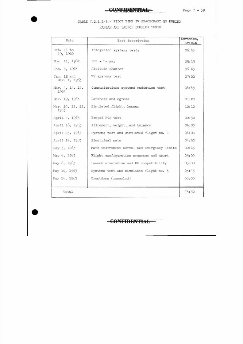
8/7/2019 Post Launch Memorandum Report for Mercury-Atlas No. 9(MA-9). Part 1 Mission Analysis
http://slidepdf.com/reader/full/post-launch-memorandum-report-for-mercury-atlas-no-9ma-9-part-1-mission 220/344
JVF1DEIVTIAL"
-
Page 7-59
TABLE 7.2.1.1-1.- PILOT TIME IN SPACECRAFT 20 DURING
HANGAR AND LAUNCH COMPLEX TESTS
Date
Oct. 11 to
19, 1962
Nov. 11, 1962
Jan. 5, 1963
Jan. 12 and
Mar. 1, 1963
Mar. k, Ik, 15,1963
Mar. 19, 1963
Mar. 20, 21, 22,
1963
April U, 1963
April 18, 1963
April 23, 1963
April 2 , 1963
May 3, 1963
May 6, 1963
May 8, 1963
May 10, 1963
May 14, 1963
Total
Test description
Integrated systems tests
RCS - hangar
Altitude chamber
TV systems test
Communications systems radiation test
Darkness and egress
Simulated flight, hangar
Prepad RCS test
Alinement, weight, and balance
Systems test and simulated flight no. 1
Electrical mate
Mark instrument normal and emergency limits
Flight configuration sequence and abort
Launch simulation and RF compatibility
Systems test and simulated flight no. 3
Countdovn (canceled)
Duration,hr:min
06:45
03=15
06: 5
07:00
04: 5
01:20
12:10
00:50
0 :00
0 :00
0 :30
00: 5
03:00
05:00
03: 5
06:00
73:50
C O N F I D E N T I A L
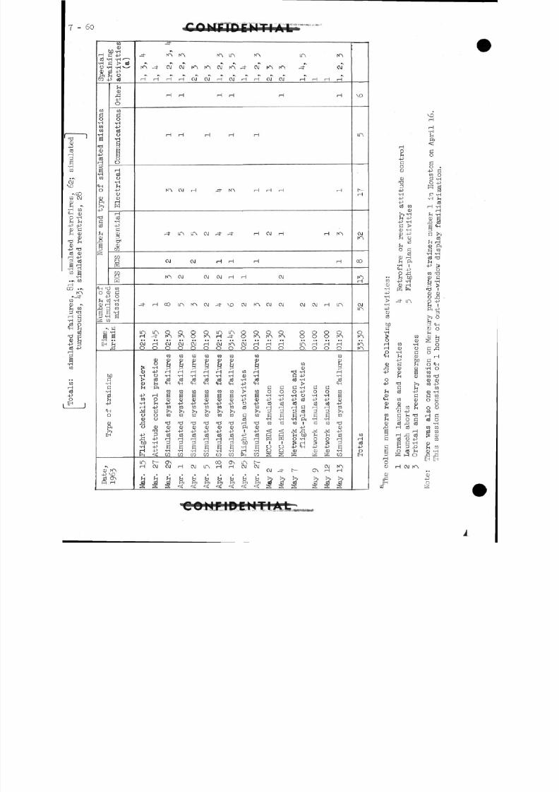
8/7/2019 Post Launch Memorandum Report for Mercury-Atlas No. 9(MA-9). Part 1 Mission Analysis
http://slidepdf.com/reader/full/post-launch-memorandum-report-for-mercury-atlas-no-9ma-9-part-1-mission 221/344
6o ctw i'-J'iW•»».,•.-
H0 3 »•HO •CU
ra 4
lated missions
m
O
-p
Gc d
jo -isqumjtf
CU
^
tf
*rc•r0
4-
^C
jE -
c u
a
:tivities
(a)
J 03
C U
4^
0
Communications
Electrical
Sequential
raoK
O
missions
a•Ha
i
iD
^
^3H3
H
)
i
^H
^
H
w,
H H H H O J O J H O J H H O J O J HHHH
H H H H H H
H H H H H
N ~ N . OJ H _3- r < ~N HHH H
------H 0, H
O J OJ H H H H
r<~ N OJ OJ OJ H H OJ
-3" H CO ITN rO OJ -3" \O OJ K"N OJ OJ OJ OJ H LTN
t r\ LTN o o o o LTN ir\ o o o o o o o oH - = | - r < ~ N K s \ O K ^ H - H r O f < " N . t < ~ N r < ^ O O O i ^ N
O J H O J O J O J H O J r O i O J H H H m H H HO O O O O O O O O O O O O . O O O
ra ra co r a r a r a co r ac u c u c u c u c u c u c u c u c u
C U - P H H H H H H t o H 13 -H H•H O -H -H -H -H -H -H 0) -H G 4J -H^ c d c d c d c d c d c d c d T H o ^ c d * H c d
4 - j H g g a g a & -H a - ri - H - H o - H - H aC O O C U C U ( 1 ) C U C U C U +
3C U 4
J4
J4 J c d 4
:' 4
JC D
H 4 - 5 r a t o c o r a t o r a c d " ' ' d ' d H c l H H r a
C U O 03 'H *H 'H ft -H -H
O C U C U C U C U C U D C U f t C U 4 ^ C U'd 4 -
; >4 -
34
J4 -
: )4
J4 -
3 1 -P ^ <t! J^ JIH ,M r^ 4-5
^ 4J
H r H H H H H ^ ! H F Q p H O- H o OH
H -P -H -9 -H -H -H -H H -H O O 0) CD CU -H
m f CJN CO CJ\ IC\ £~H O J O J H O J L P x H H O J O J O J K ^ s
O J J- I>- ON H H
!!ltt!tS!!!!iIII
VO
,n
H
O JKA
CO
H
O JITN
O
K
Totals
» •ra
•H4-3•Ht>
•H4-J
0cd
MG•H
§
HH0
MH
0)!
4-3
o4-3
£- 4
«
ewhO JrO
g
P
JH
G
§HOO
c urC
EH
H0
4JCoo
O J
3-P•H
-P-P
03 tocur>i *H
fH 4-1
-P -HG >C U -H
K - Scd
o c:c d
C U H^H ft
•H 1CH 4J0 £1fn bO4^ 'H
C U HK f
- LTN
raC D
ra -Hcu o
•H fif H C U
-P bOd ?Hc u c uc u a?H CU
r"Cf r*J
SH ?H
cd -Pa
W C Uc u c u& W f-tO -P
£H H d
P 0 C03 f> cdH cd
HH cS03 O 4->a G 'HH 0 £*O cd ^S^ 0
H OJ fO
VOH
H•H
ft
ao
C0.
•p ara oP -H0 -P
c- 3e -H
•H ^Hcd
H -HH£H -Hc u an^a ^p
Cl rcd
fH H
CU ftG ra•H -H
cd ^h
-P >0
C Q T3
C U G
-d fc u c u0 £!
O 4^
ft -P
>5O
^CH0 O
SOc: ^oH
GO <H•H Orara fdc u c uM -P
C OC U -HG WO G
OO 0
H Gc d o
•Hra racd raP cu
co0)fn racu -H
EH E H
cu-p0
COifFIPEMTIAL
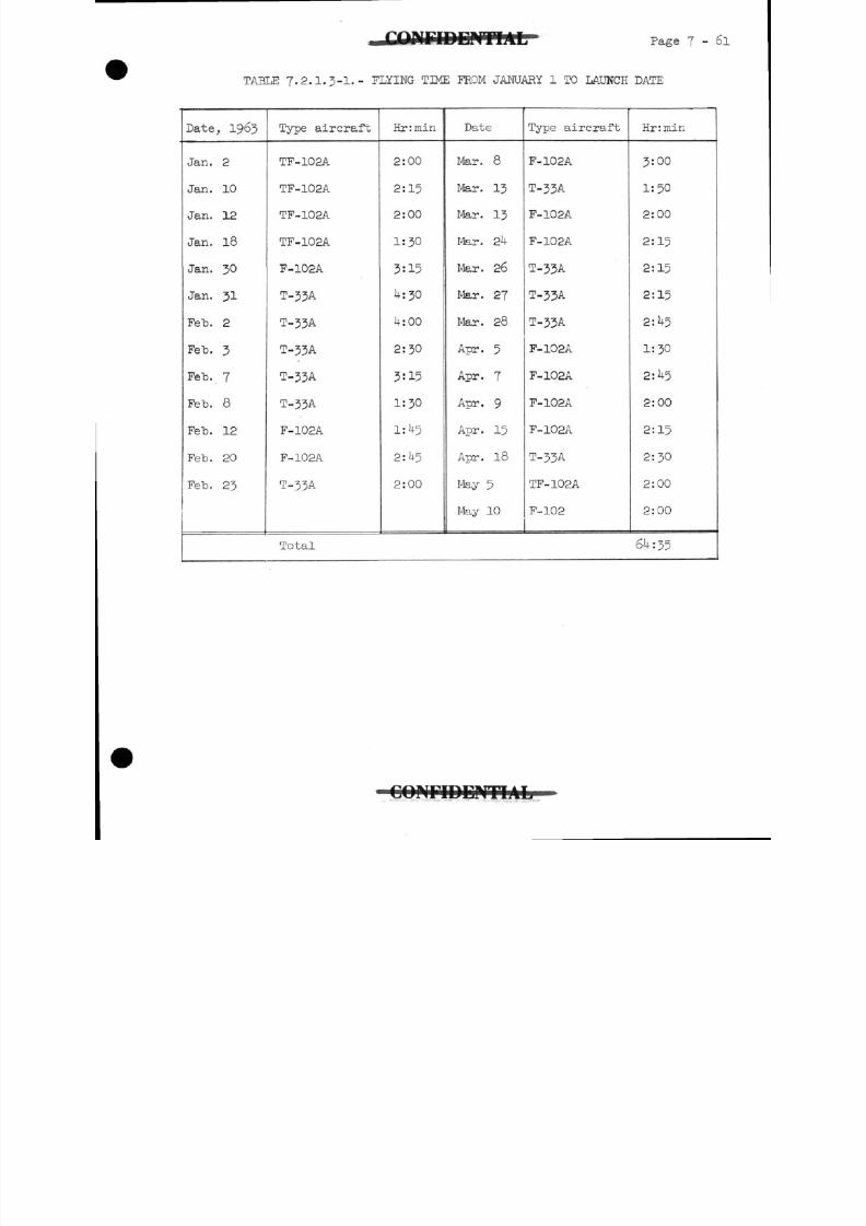
8/7/2019 Post Launch Memorandum Report for Mercury-Atlas No. 9(MA-9). Part 1 Mission Analysis
http://slidepdf.com/reader/full/post-launch-memorandum-report-for-mercury-atlas-no-9ma-9-part-1-mission 222/344
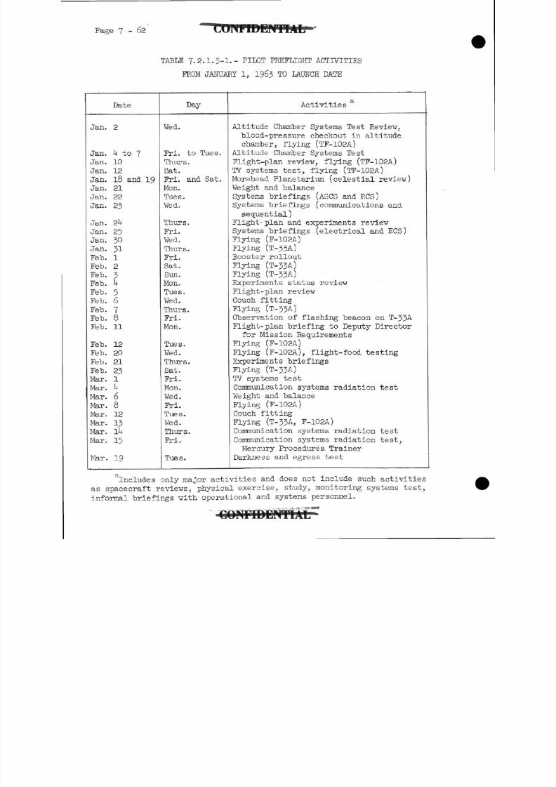
8/7/2019 Post Launch Memorandum Report for Mercury-Atlas No. 9(MA-9). Part 1 Mission Analysis
http://slidepdf.com/reader/full/post-launch-memorandum-report-for-mercury-atlas-no-9ma-9-part-1-mission 223/344
Page 7-62
TABLE 7.2.1.5-1.- PILOT PKEFLIGHT ACTIVITIES
FROM JANUARY 1, 1963 TO LAUNCH DATE
Date
Jan. 2
Jan. U to 7
Jan. 10
Jan. 12
Jan. 18 and 19
Jan. 21
Jan. 22
Jan. 23
Jan. 2
Jan. 25
Jan. 30
Jan. 31
Feb. 1
Feb. 2
Feb. 3
Feb. k
Feb. 5
Feb. 6
Feb. 7Feb. 8
Feb. 11
Feb. 12
Feb. 20
Feb. 21
Feb. 23
Mar. 1
Mar. U
Mar. 6
Mar. 8
Mar. 12
Mar. 13
Mar. lU
Mar. 15
Mar. 19
Day
Wed.
Fri. to Tues.
Thurs.Sat.Fri. and Sat.Mon.
Tues.
Wed.
Thurs.
Fri.Wed.
Thurs.Fri.Sat.Sun.Mon.Tues.Wed.
Thurs.
Fri.Mon.
Tues.
Wed.Thurs.Sat.
Fri.Mon.
Wed.
Fri.Tues.
Wed.Thurs.
Fri.
Tues.
Q
Activities
Altitude Chamber Systems Test Review,
blood-pressure checkout in altitude
chamber, flying (TF-102A)
Altitude Chamber Systems Test
Flight-plan review, flying (TF-102A)
TV systems test, flying (TF-102A)
Morehead Planetarium (celestial reviev)Weight and balance
Systems briefings (ASCS andRCS)
Systems briefings (communications andsequential)
Flight- plan and experiments reviewSystems briefings (electrical andECS)
Flying (F-102A)
Flying (T-J5A)
Booster rolloutFlying (T-JJA)Flying (T-3JA)
Experiments status review
Flight -plan reviewCouch fitting
Flying (T-JJA)Observation of flashing beacon on T-33A
Flight-plan briefing to Deputy Directorfor Mission Requirements
Flying (F-102A)
Flying (F-102A), flight-food testingExperiments briefingsFlying (T-33A)
TV systems test
Communication systems radiation testWeight and balance
Flying (F-102A)
Couch fitting
Flying (T-JJA, F-102A)
Communication systems radiation testCommunication systems radiation test,Mercury Procedures Trainer
Darkness and egress test
Includes only major activities and does not include such activitiesas spacecraft reviews, physical exercise, study, monitoring systems test,
informal briefings with operational and systems personnel.
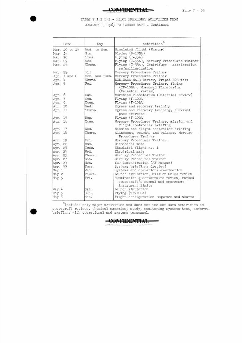
8/7/2019 Post Launch Memorandum Report for Mercury-Atlas No. 9(MA-9). Part 1 Mission Analysis
http://slidepdf.com/reader/full/post-launch-memorandum-report-for-mercury-atlas-no-9ma-9-part-1-mission 224/344
I E N T I A L Page 7 - 6 3
TABLE 7.2.1.5-1.- PILOT PREFLIGHT ACTIVITIES FROM
JANUARY 1, 1963 TO LAUNCH DATE - Continued
Date
Mar. 20 to 2k
Mar. 2
Mar. 26
Mar. 27
Mar. 28
Mar. 29
Apr. 1 and 2
Apr. U
Apr. 5
Apr. 6
Apr. 7
Apr. 9
Apr. 10
Apr. 11
Apr. 15
Apr. 16
Apr. 17
Apr. 18
Apr. 19
Apr. 22
Apr. 23
Apr. 2}4
Apr. 25
Apr. 27
Apr. 29
Apr. 30
May 1
May 2
May 3
May ^May 5'4ay 6
DayWed. to Sun.
Sun.
Tues.
Wed.
Thurs.
Fri.Mon. and Tues.Thurs.Fri.
Sat.Sun.
Tues.
Wed.
Thurs.
Mon.
Tues.
Wed.
Thurs.
Fri.
Mon.
Tues.Wed.
Thurs.
Sat.
Mon.
Tues.
Wed.
Thurs.
Fri.
Sat.
Sun.
ton.
Activities
Simulated flight (Hangar)
Flying (F-102A)
Flying (T-33A)
Flying (T-33-M, Mercury Procedures Trainer
Flying (T-33-M, Centrifuge - acceleration
re familiarization
Mercury Procedures TrainerMercury Procedures TrainerDOD-NASA MA-9 Review, Prepad RCS test
Mercury Procedures Trainer, flying(TF-102A), Morehead Planetarium(Celestial review)
Morehead Planetarium (Celestial review)Flying (F-102A)
Flying (F-102A)
Egress and recovery training
Egress and recovery training, survival
pack exercise
Flying (F-102A)
Mercury Procedures Trainer, mission and
flight controller briefing
Mission and flight controller briefing
Alinement, weight, and balance, MercuryProcedures Trainer
Mercury Procedures Trainer
Mechanical mate
Simulated flight no. 1
Electrical mate
Mercury Procedures TrainerMercury Procedures Trainer
Yaw demonstration (AF Hangar)
Systems briefings (review)
Systems and operations examination
Launch simulation, Mission Rules review
Examination questionnaire review, markedspacecraft's normal and emergency
instrument limits
Launch simulation
Flying (TF-102A)
Flight configuration sequence and aborts
Includes only major activities and does not include such activities as
spacecraft reviews, physical exercise, study, monitoring systems test, inform
briefings with operational and systems personnel.
C O N F I D E N T I A L
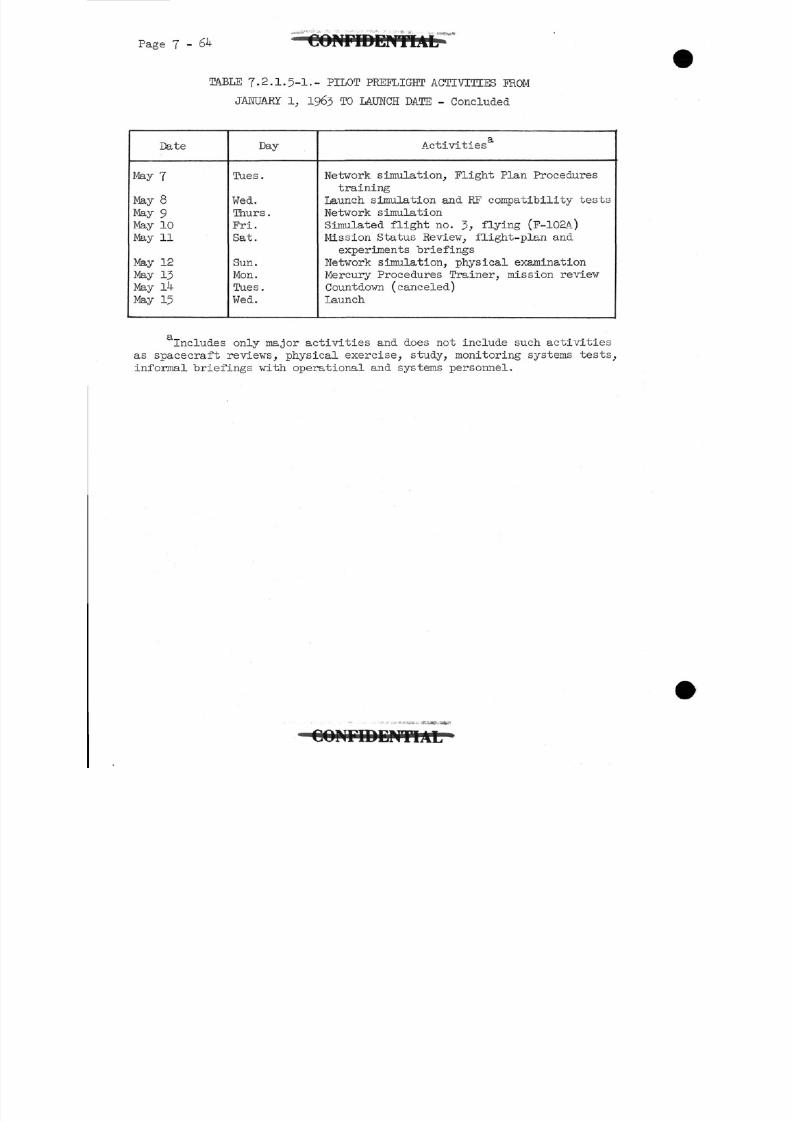
8/7/2019 Post Launch Memorandum Report for Mercury-Atlas No. 9(MA-9). Part 1 Mission Analysis
http://slidepdf.com/reader/full/post-launch-memorandum-report-for-mercury-atlas-no-9ma-9-part-1-mission 225/344
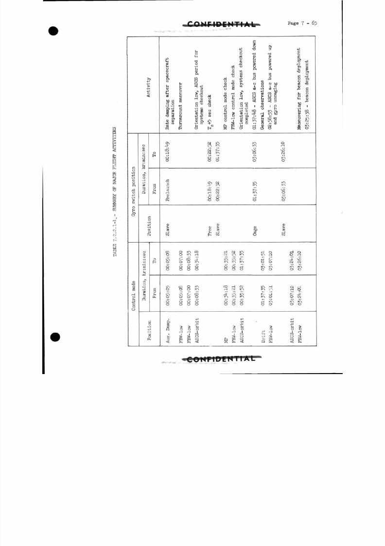
8/7/2019 Post Launch Memorandum Report for Mercury-Atlas No. 9(MA-9). Part 1 Mission Analysis
http://slidepdf.com/reader/full/post-launch-memorandum-report-for-mercury-atlas-no-9ma-9-part-1-mission 226/344
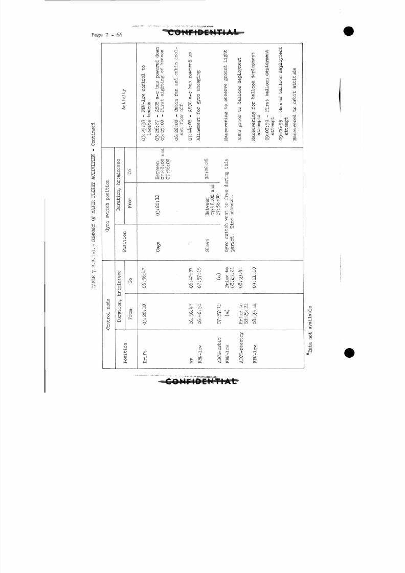
8/7/2019 Post Launch Memorandum Report for Mercury-Atlas No. 9(MA-9). Part 1 Mission Analysis
http://slidepdf.com/reader/full/post-launch-memorandum-report-for-mercury-atlas-no-9ma-9-part-1-mission 227/344
Page 7-66 IPCMTM.LI
Activity
g•H-P•Hra
ajdo
-p
Sto
I
Control mode
Duration, hr:min:sec
oS
gJHf^
Position
Duration, hr:min:sec
OEH
fHs
Position
p ' +3> fl H -P -PCO O 0 p, 43 -P C 0)
T J o o a w ) C D Sto o 'H -p cu s ?\
Td 0) Tf H C § S, Oa;P c CD CD R, o H
O ?H - H f n • d S O H P n.p CD IH p CD c !>> H ft cu <u
Is o co > w d o f t a j ' d ' c l
HO o o C O H <D T:! 3O f t S D PH-H M PH d a -pr4 fl Tl M M <U C O -H- p c Q H d r a c t i ti C O O -pC 3 -P CO a o <D O O rH -PO f l f f PC S r t O r H r j C d0 h O C a f n O H H o i
O ' H c d O ( U O H c d ^ - Pg| I d H - i 1 O M H t S P - H
H i Oj ^ l p r HP T J PH - P C R O d J + 3 C ^ Hi r t r a t o - H M t i O p ^ w o o^ r OO^p ^O O O M Op qo M' H c d ' H M^ i -P O -H CD Of L , 0 } < ! f n V O < Z O + 1 p c n C Q - P
0 CH W) hfl1 , 0 1 1 l> i C f- t C r a i 1 T3
O - p - H O - H - P - p - P O )
C O (D t O OHir\c fn -H f n P<O\ P( r<^P<^r^HJOjo o^Ooj <u M D g i r \ S L f \ B a J.. oj .. •• •• •• S > PH >. a) .. (U •• (D >L P i O V O l T N C \ J - P - ^ - ( U 3 d - p o - P ^ Q - P Sc v i o o j o ojcj-c ID ra a > 4 J o - p O- p < u..H"" • • C B - - - H C O C o j " C d - - a i C
r O v H ^ L T \ V O [ ^ H C d W o j Q A O N O iQOOOO< ! § <; s ; oos
1C O
O O CO raa o o c\j -H0 .. .. •• J3(U 03 MD VO -PS = j - in cu4j .. .. •• M
0) t t - O CFQ O O H -rH
M
-d -d
cfl (UCD
O O O H C O O CHfl
VD <D CO V3 O OOJ > -d- 1TN -p C
+3 .... 3K\ 0) t C- +3 Co pq o o a 3
< u3 (D
|3
ra -dcu O
(U > O -H
M cd H httf H S (DO CQ C5 ft
t H IT\ O H -=t- Oj- in H -pcv j -d- H
VO C M t C S ^ I A O A Hto, J- ITN - O OJ U~N H
•H ••VO VD t fl OO CO ONO O O ffi O O O
O C H LH O H -*H J- UA H -p 0] -=t
vo vooj ^ r t h L T N C T soj N \ _4- m ^ o GJ m
(Ov VD VO l>- S - t CO COO 0 0 O ffi O 0
&£ Sft 0)
> JH > <D ^O O O JH O
-p rH 1 H 1 rH
S i 8 4 8 s § e s § 1 3
•H
8
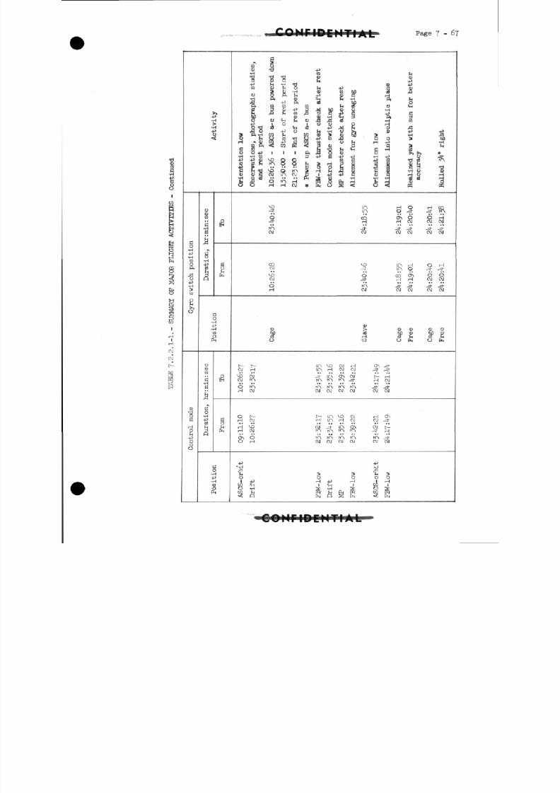
8/7/2019 Post Launch Memorandum Report for Mercury-Atlas No. 9(MA-9). Part 1 Mission Analysis
http://slidepdf.com/reader/full/post-launch-memorandum-report-for-mercury-atlas-no-9ma-9-part-1-mission 228/344
CMTIAL Page J - 6-J
Activity
Gyro switch position
Control mode
Duration, hr:min:sec
•
g
Position
o
en
B•rH
S
O•H
rH
•
rH
Position
". 3
W O
0 ) -d -P
Td "d -d 8 IU
d 0 ) O M .p•P rH vH >d OJ -Pt o f l > M o H 49 do)
I* CD *H V M b f l (JO ,Q
tl O 1 O O O rl
' d c o Vial f M ft O Ao -P o tl "C Si n " ^ ti
H ^ a j w - p c W c o o h '"''S > r (
O O - P I I I P n A Q O ) >, >, o• H - H C O a^l^j^j -H-P t ) JK- p _ p d j v o o o t o n 4 ^ a T j c d f * \
a ) o f l c v i i o , o j S i 4 i . p d o j c r d ° ^ j
C5 O rH rH CVJ ^f F*-\ C? j < o <ij pi pq
^P in H o H co•7. f> 9 -5 -S T?
S C O O\ O O HH H CVI CVI CVJ
OJ OJ OJ OJ OJ OJ
CO VO 1T\ rH O rH
O J j- ir\ o J- _*^O O CO O\ O OO J J - rH H O J O J
O rA j- -* -4- -=J-H OJ OJ OJ OJ OJ
t oj bo o w) a)rH US rH «J rHra o PR o PR
OJrH I T N r H O J O J -* J-
VO OJ - IT\ ON OJ t HO J N A K> hOtO\ J- H OJ
H OJ O J O J O J O J O J O J
Ot^ I ^ I A VOOJ HO\H OJ HmHOJ OJ-d-
HOJ rOfOi l^N^J-rH
O H c v i c v i o j o j c v o j
-P H^••H -H
" S > > " S \ ?1+3 H 4J H 1 H
co <*H I IH I CO iO -H S -H IS O J5
C V J
cvi
t
OOHriDCHTIAL
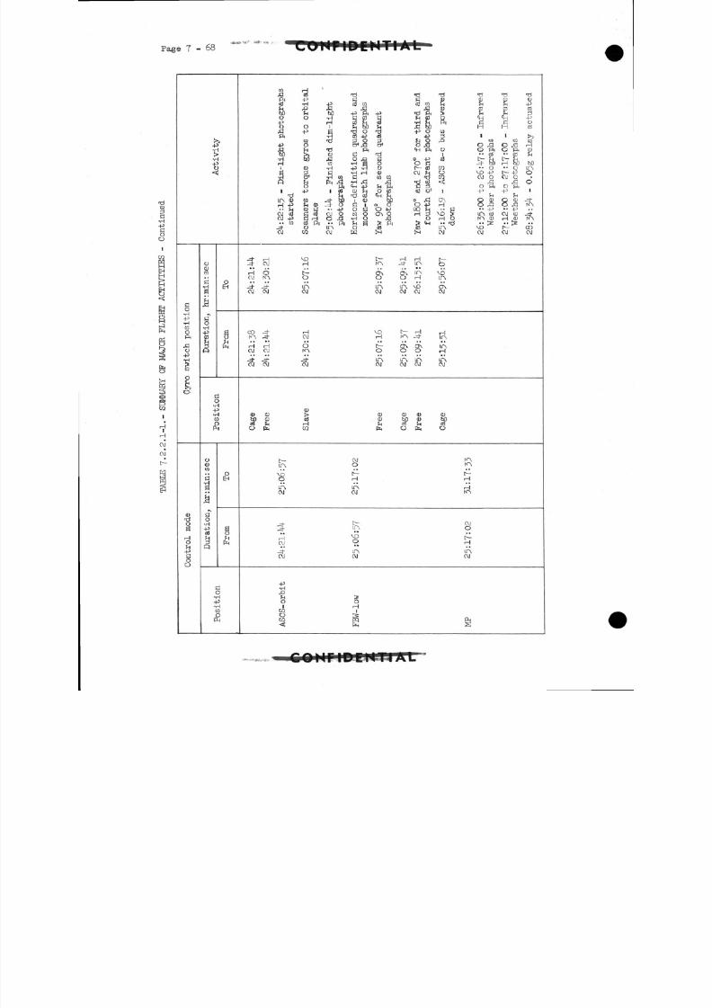
8/7/2019 Post Launch Memorandum Report for Mercury-Atlas No. 9(MA-9). Part 1 Mission Analysis
http://slidepdf.com/reader/full/post-launch-memorandum-report-for-mercury-atlas-no-9ma-9-part-1-mission 229/344
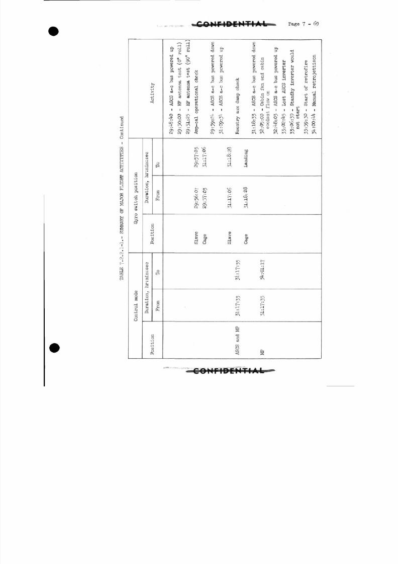
8/7/2019 Post Launch Memorandum Report for Mercury-Atlas No. 9(MA-9). Part 1 Mission Analysis
http://slidepdf.com/reader/full/post-launch-memorandum-report-for-mercury-atlas-no-9ma-9-part-1-mission 230/344
. v* -*•-Page7-69
-d01
C
o
ao•H
•P•rl
CO
Oftsio
•HJy
01
o
O J
o"rH
oM-Paoo
-iiii1<
o0)CO
C•HaM^
f To•H
-pcd
S
I1
H
i
P
OCDCO
b•r)
a
I
„co
-pcd
*3
(5
!<•l
-4
•r
Ci
P
>>3
-Ik
H3
C
oEH
a
A
5
3H0JH
OEH
gQ
^[T !
5H3H
03LI
*-*• rH C C
rH rH ? ?ft H O O ft O ft
T - I ^ O rd t) -d T f ' d
C U o O (1)0) < D B O O OM O O \ M M M - H h F H 3 c u c o0 ) D O ) D r ^ O O ) M'lH
O - P - p O O O O O H 0 ^ H - P
Pi m o >d ftft ft fto)-p oo)CD CL O T^J & U ^ *r^t o +3 - P Q) r a co c o G c c t d O ) - p Od £ 3d ,!«! d c o d - H ! > ( l ) M
C d 01 w -H cuO G C r H o o ^ ! o c d o o < H Ml O C U C O I I I ' M I W S O
" ^ " a o f t s o S - p ' c dc o c S c d - r i w c o s OJ-H r a - p c M dO -p O O c d O r T i ^ O a i c d c d drahfeg rara T J 2 ri 5 2 5 i£> "S^
4> X "in -p( l i f t I I 3 1 1 I I I M I I
o cd -p 3_ ^- o oj rH oj m £*} m o co o - rn to rn -
C O O H O O\CT\ - P C O L n O C O O J V O . p O N . O^d - in in i mo c noo-^-oooino
O N O N ^ S ON rH 0) HOJ O J N ^ K A K> ^d"o j o j o j <s o j m ps m KS ro KN ro m KN
m v o c oO O OJ bQ
t t CO THm rH rH Td
ON rH H (Soj m fn i i
t~- KN VD COO O O OJ
MD t C COin in H rH
CT\ O\ rH rHo j o j m KN
0) 01> 0) > 0)cd Sb ai Mi 1 CO rH (0C O O CO O
in c.» ..
rH O. . ..
H -=hrn KN
K> m'.O I!?
1
t1 D
rH H•• . •
m m
5£3
s^ g
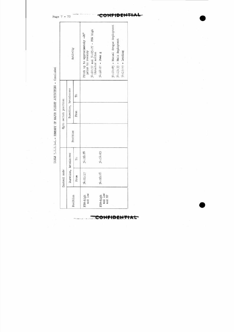
8/7/2019 Post Launch Memorandum Report for Mercury-Atlas No. 9(MA-9). Part 1 Mission Analysis
http://slidepdf.com/reader/full/post-launch-memorandum-report-for-mercury-atlas-no-9ma-9-part-1-mission 231/344
Page 7 - 7 0
+1•H
•H-PO
HO•H-p•HCO
fto
+2•H
CO
O
1gHO
-pS30
O
CO
a
r.H
ao•H
•£CD
5
oEH
Ej
HP H
ao•H
CO
O
CJ
CO
P3•Hg
g~•H+3
£_ j
3
oEH
gfH
P H
H0•H
•P•rH
CO
£
-PdCD
60 S>o -H OO JS HOJ ft
1 IS (Dpq -d -P
>> PH H
H CU CDCD 1 3 B-P MS;
cS C ~ - O O
X >» i r\ CD hpO ^ O G M H - d C(H -P •• O 08 -HPHC " H Vj j T
cd Q ) o d j c d c c j c d^ T^ a i P H J5i l J5j h-1
O fl- P o aJ ^H i ill
-p oPJ t .jp t ^^^ j>r\ Q\
ft ° OJ 2 OJ -' IA ON
-p ft •• .p
P H ro\ ro\ fO» ro\ K^
C O t <~ \C J o
C O j-'O H
KN KA
1^- COH OJ
H CO0 0
N~\ hO\
"* ^ PHMH bDH S•H -H4n Tj 4n TJ "d
S Oi g CS O
P H P H
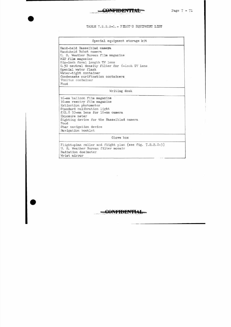
8/7/2019 Post Launch Memorandum Report for Mercury-Atlas No. 9(MA-9). Part 1 Mission Analysis
http://slidepdf.com/reader/full/post-launch-memorandum-report-for-mercury-atlas-no-9ma-9-part-1-mission 232/344
Page 7-71
T A B L E 7.2.2.2-1.- PILOT'S E Q U I P M E N T LIST
Special equipment storage kit
Hand-held Hasselblad camera
Hand-held Ro~bot camera
U. S. Weather Bureau film magazine
MTT film magazine
Six-inch focal length TV lens
O.JO neutral density filter for 6-inch TV lens
Special water flask
Water-tight container
Condensate purification containers
Vomitus container
Food
Writing desk
l6-mm balloon film magazine
l6-mm reentry film magazine
Extinction photometer
Standard calibration light
f/2.8 50-mm lens for l6-mm camera
Exposure meter
Sighting device for the Hasselblad camera
Food
Star navigation deviceNavigation booklet
Glove box
Flight-plan roller and flight plan (see fig. 7-2.2.2-3)
U . S. Weather Bureau filter mosaic
Radiation dosimeter
Wrist mirror
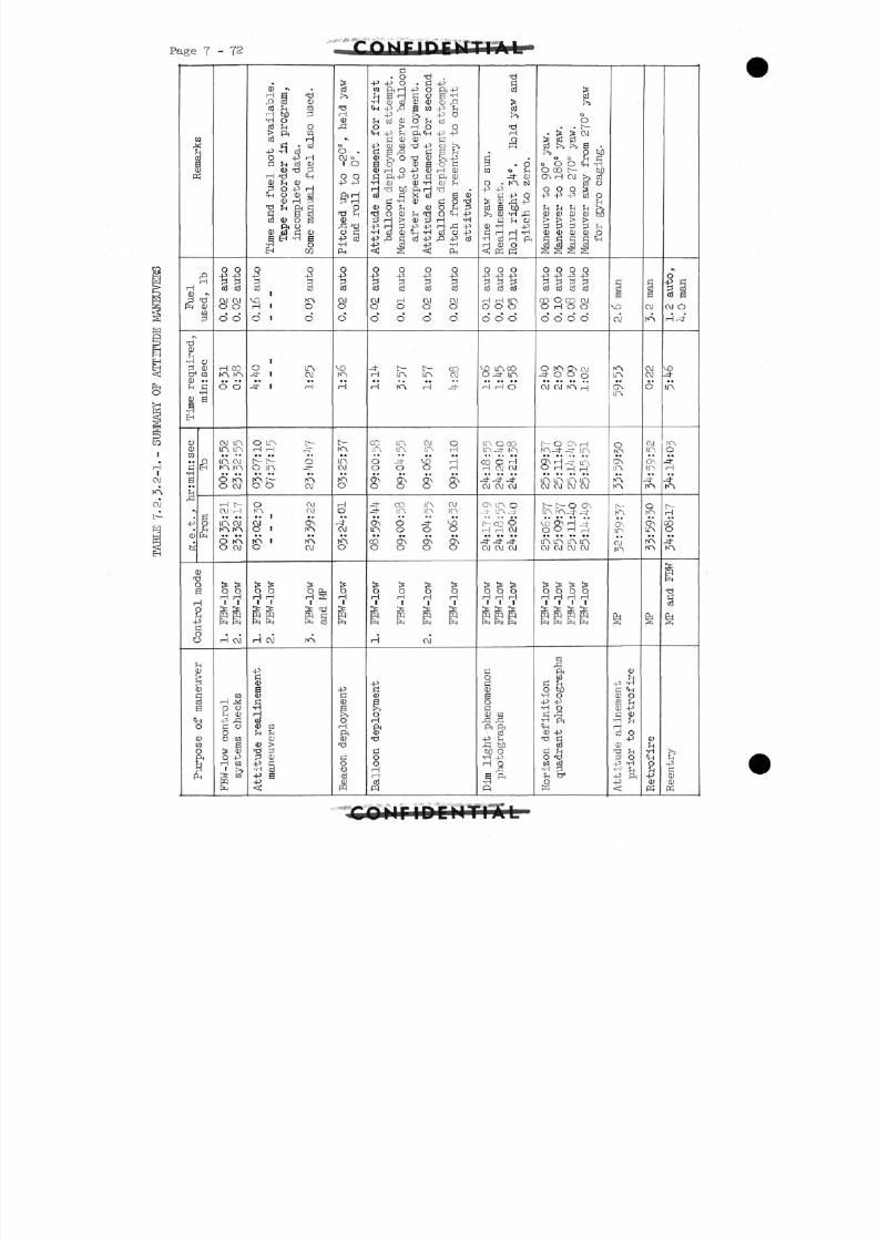
8/7/2019 Post Launch Memorandum Report for Mercury-Atlas No. 9(MA-9). Part 1 Mission Analysis
http://slidepdf.com/reader/full/post-launch-memorandum-report-for-mercury-atlas-no-9ma-9-part-1-mission 233/344
Page 7 - 7 2>*'X n i- i ri i-
c1
1!i
P
H0)
1
•N
C Dfn•H
CDH
CD
HEH
oC U03
•Ha
-pC U
w
<i
ip
<!4
S<£
ij
i(
qi
(
P
aAH
da)
rD
H
CD
CD
P
O
CD
ra
fl•Ha
oEH
0
D '3
HDH3
D3
H
u>
3U
d3
H
D
VaD3lH
3M
0 0+3 +3
cd c d
S0
o o
rH COKN. fTN
0 0
oj min m
in cvj
o m
o cu
Ht-OJ H
in oj
8 IO\O J
Is Iso oH H1 1
IS,.
H OJ
CO
O 0H C D-P flfl 0Oora
aIs S0 -PrH ra1 >>
p"[
E
.0) «.na iscd f-i raH bO 3•H 0
o 3 H O> ft Mcd H
fl • cd-P -H cdO -P rH
fl M c d C D< u fd 2
i j r[j CH
C D H CDS O -P H
CH O C D o jC D H P
" S ^ § * §o s a > o a
ft oCD 03 fl 0)a E H - H a•a o
EH ra
0 0
"§ ^o 3 c d
VD mrH1 O
O 1 O
1
o in-=t 1 OJ
-=t 1 H
o in c--H rH -=J-
t~- D Oo in _*f<- [~_ |Ov
O O OJ
O CVJN"N, CM
O J ONO I ro
N \ 1 |f\O OJ
O O O EHHH H §
i?H S "flmm m o3
. . ,
H OJ MA
-Pfl
CD
aC Dfl•HrH
cdcu raH H
CD
d) >rci ^0 CD
4 ^ > f l•H cd-p a
<
f5
c < 3PS
r^j
HO JA
*\Q
0.O J o1 O
0 0-P -P
ft 1 1p 1 1
•d 80c~] r^j
O fl
-P o3•HFM
0-P
cd
0
0
VD
H
C
inO J
fO,
O
HO
CV J
K>O
orH
1
S
-pflCD
S>OrH
ft(U
-d
rOoC o
dJ
m
fl• o 'd
4^ 4-5 O . fl -Pra ft H 45 O ft -P
•H d) cd CD CU CD r^CH -p ,Q a
M-P rH
4^ Ss -P OH CO CD O f -i COO > H O O
CH -p H ft CH 4J 4-f l C D C D f l
-P 0 M rd _p CD >,
C U & O T3 D >j 4J3 O CD g 0 flC U H O 4^ CU H CDfl ft 4^ CJ fl ft CU
•H CD d) -H CD ?HH fd bO ft i 1 T^ •c d fl X o3 a cu
fl -H CU fl O 'dC U O l CD O M P
P H > CD Ji rH -H•P ] 1 S -p -p 1 i pfl 4>
•H cd CD CH -H cd o 4^>
+3 (rt -p -H
<; g < p..
o o o o4J -p 4J +0
o 3 c d c d c d
0000
0000
• t C COH in in oj, | [O\ r-J_J-
co in 01 oin m in i i
O -dr VD HO O O H
O N O N O N O >
O O O O
-^ co in ojJ- in in in
O N O -4- VDin o o o
oo ON. ON ON0000
Is Is > >O O O OH H H HI 1 1 1
Is Is Is Ispq pq pq pq
. .
H OJ
4^flC D
P 3
OHp|
d )•d
flooHH
$rn
r^Jrtcd
[5
cd
rHOM
fl •3 . ora o £n
-* CUo • m w4J -P
a -p o> CD fl 4^C d B MS CU -H fl
fl !H 0CU -H JJfl H H -H•H cd H ftH CU O< q ffi K
o o o-p -p -p
cd o 3 c d
H H moo o
0 0 O
VD in coo - = t - in
H H O
in ocoin j-N^CO O H
H OJ OJ
-i"-i* j-'O J O J O J
O\ Lf\ C)
b-CO OH rH OJ
-3- -d- -4-OJ CXJ OJ
> Is >o o oH rH rH
1 1 1
gig
flOflcua0fl0) CQfl flft ft
c d
f(~] f fl
to o•H -p
H 0
S Pi•rH
o
IsJ>J
0
0
• Is Is oj|5 O/ 03c d > 3 > i a>i O bD
O 0 H fl
o O O C H - HO CO t-- MO N H OJ !> j o3
cd oO O O Is4 ^ 4 ^ 4 ^ 0 5 0
t ^
C D C D CD C D b D
p p 3 P JH0) CD CU CD Of l f l f l f l C H
mi0000-p -p -p +5
c d c d c d c d
C O O CO OJO H O O
o o o o
5£&gO J OJ K> H
h- O O N HK A _ d - -4- inQ ,_) . !_
0 H H H
in in in inO J O J O J O J
h- t O ON
VD CJN H J-0 0 H H
in in in inOJ OJ OJ CVJ
> > Is Iso o o oHH H H1 1 1 1
Is is is Isp q p q p q p q
raflftoj
fl M
0 bO•H 0
-P -P•H ofl fl•H ft
C D -Prd fl
cdfl Ho "dN OJ•H p^ a
1
Q
K
fl
VD
c v j
in
ONin
o
ONin
ir\
KA
t"
O-LT A
C VJ
§
C DM
-p -H
C D OB >HC D -Pf l CD•H MHc d o
4-JC D•d fn? O
-P vH•rH Jn]
4J ft
<
fl
C VJ
^
O JO J
o
C VJ
in
ONin
_4 -
K\
0KN
O Nin
KA
^
§
C Df-l•HCH0
4->C DK
f\
O•P flS cdc d a
cu o
H-H-
VD
in
o_3-H
_H ^
KN
H
COO
_JK\
^S
•dflcd
j>j
-pflcucuK
o
M
rai
HC V J
o
4 IF ID C If
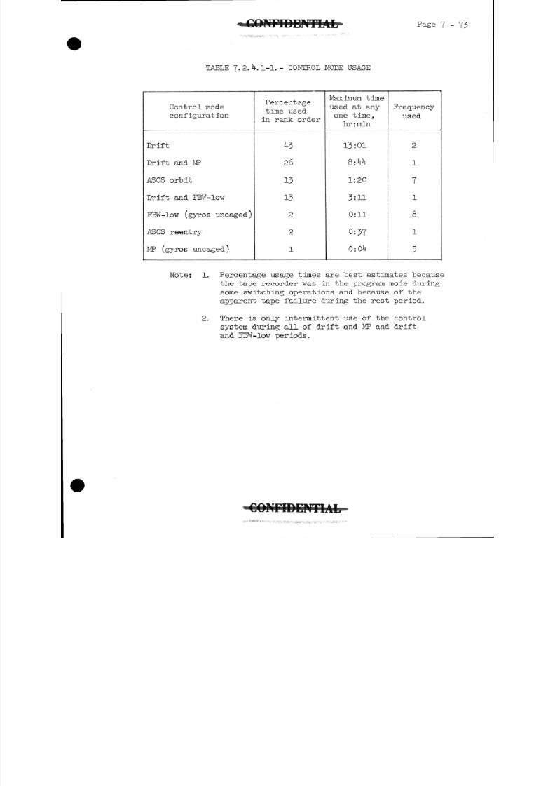
8/7/2019 Post Launch Memorandum Report for Mercury-Atlas No. 9(MA-9). Part 1 Mission Analysis
http://slidepdf.com/reader/full/post-launch-memorandum-report-for-mercury-atlas-no-9ma-9-part-1-mission 234/344
WriDCNTIAL Page 7-73
TABLE 7.2.4.1-1.- CONTROL MODE USAGE
Control mode
configuration
Drift
Drift and MP
ASCS orbit
Drift and FBW-low
FBW-low (gyros uncaged)
ASCS reentry
MP (gyros uncaged)
Percentagetime used
in rank order
43
26
13
13
2
2
1
Maximum time
used at any
one time,
hrrmin
13:01
8:44
1:20
3:11
0:11
0:37
0:04
Frequency
used
2
1
7
l
8
1
5
Note: 1. Percentage usage times are test estimates "because
the tape recorder was in the program mode during
some switching operations and because of the
apparent tape failure during the rest period.
2. There is only intermittent use of the control
system during all of drift and MP and drift
and FBW-low periods.
C O N F I D E N T I A L•
8/7/2019 Post Launch Memorandum Report for Mercury-Atlas No. 9(MA-9). Part 1 Mission Analysis
http://slidepdf.com/reader/full/post-launch-memorandum-report-for-mercury-atlas-no-9ma-9-part-1-mission 235/344
7 7 ^
7-3 Pilot's Flight Report
7.3.1 Introduction.- The MA-9 mission was designed to evaluate
the operational and aeromedical aspects of the man-
spacecraft system in a manned one-day mission. The flight
of Faith Seven has demonstrated this capability and, I
hope, has shown the way for expanded capabilities in the
manned space-flight program.
Because of the extension of the flight duration for this
flight, there was much more time available for evaluating
systems, conducting experiments, and determining man's
adaptability to the space environment.
The name of my spacecraft, Faith Seven, was chosen for
three reasons; a belief in God and country, a loyalty tomy parent organizations, and a confidence in the entire
Mercury space team.
This flight was an excellent example of a well coordinated,
well disciplined, voice procedure between the spacecraft
and the world-wide tracking network. The information
received onboard Faith Seven was clear, concise, and served
to keep me continuously updated throughout the flight.
In my opinion, it is pertinent that this data flow was so
complete that I felt confident of my ability to accomplish
the mission successfully in the event of an unexpected
loss of air-ground communications.
The remaining context of this report will be a chronological
discussion of the flight from launch to recovery.
7.3.2 Launch.- Launch activities were well planned and were accom-
plished smoothly. We were always on or slightly ahead of
schedule, and I did not feel at all rushed for time. The
donning of the Mercury pressure suit for my second flight
attempt was accomplished in good order, and we arrived at
Launch Pad Ik on schedule. I was inserted into the
cockpit, and we had completed the necessary checks
7 minutes ahead of the scheduled time for gantry removal.This time, the gantry came back without any delays, and
the countdown proceeded very successfully with lift-off
occurring 4 minutes behind schedule.
The time interval between my insertion into the spacecraft
and lift-off did not seem excessive, although insertion
GONriDCHTIAL
8/7/2019 Post Launch Memorandum Report for Mercury-Atlas No. 9(MA-9). Part 1 Mission Analysis
http://slidepdf.com/reader/full/post-launch-memorandum-report-for-mercury-atlas-no-9ma-9-part-1-mission 236/344
8/7/2019 Post Launch Memorandum Report for Mercury-Atlas No. 9(MA-9). Part 1 Mission Analysis
http://slidepdf.com/reader/full/post-launch-memorandum-report-for-mercury-atlas-no-9ma-9-part-1-mission 237/344
Page 7-76
would; however, the thrust of the posigrades gave me a
distinct boot in the rear.
Window discoloration, or smudging, occurring during powered
flight. The window appeared to be smudged in two areas.
The first smudge was streaks, similar to powder burns, on
the outside of the window. The second appeared to be a
solid, greasy, coating on the inside of the outside pane
of glass. It appeared oily when I looked through it with
direct light; but with oblique light, it blotted out the
external view and resembled ice or frost.
7 - 3 - ^ - Orbital flight.- The turnaround maneuver felt just as it
did on the procedures trainer. I went to auxiliary damping
control mode, waited for a short interval, and then selected
fly-by-wire control and started a k°/sec left yaw rate using
instruments. I did not pitch down because we had calculated
that a left yaw rate would result in a slow negative pitch
rate. However, the spacecraft did not pitch down as much
as expected during the turnaround; and, consequently, my
pitch attitude was still well above orbit attitude at com-
pletion of the maneuver.
Immediately after turnaround, my attention was attracted
to the booster, which was not more than 200 yards away.
I could read the lettering on the sides and could see
various details of the sustainer, such as the tanks. It
was a very bright silver in color, with a frosty white band
around the center portion of it. It was still wisping
lox and fuel from the aft end. It was yawed approximately
15° to 20° to its left. I had it in sight for a total of
approximately 8 minutes. The front end was slowly turning
in counterclockwise rotation'. The last time I saw it, it
was turned about 70° to the azimuth at which I had departed
from it. I began to drop slowly down to my -3 -°pitch
attitude. After selecting ASCS control, I pulled the
l6-mm camera out of its bracket and took a short film
burst of the booster with part of the east coast of the
United States and Cape Canaveral in the background;
however, the booster had moved some distance away by thistime.
I agree with Scott Carpenter that visual perspective
changes when you go into zero-g. The cockpit did seem to
be somewhat differently located in perspective to myself.
You move up forward in the seat, regardless of how tight
your straps are cinched. The ditty bag (special equipment
storage kit) on the right seems to be a different angle
to you than it is when you are on the launch pad. I did
8/7/2019 Post Launch Memorandum Report for Mercury-Atlas No. 9(MA-9). Part 1 Mission Analysis
http://slidepdf.com/reader/full/post-launch-memorandum-report-for-mercury-atlas-no-9ma-9-part-1-mission 238/344
WriDCNTIAL Page 7 - 77
feel very distinctly that I was sitting upright. Most of
the time I felt as if I were lightly floating. A couple
of times I felt almost as if I were hanging upside down
because of the feeling of floating into the shoulder
straps. Every time I "dropped" something, I grabbed below
it, expecting it to fall, (items stayed close to the
place I put them when the cabin fan was off.)
Speed is very apparent when overflying clear or broken-
cloud areas. You definitely have a feeling of really
traveling along. If the cloud is a solid deck underneath
you and you don't have any other motion cues, you have a
very slow, floating feeling.
You really need to use automatic control on the first
orbital pass or to have a low work load in order to
collect your senses, to acclimatize yourself to this new
situation, and to organize the flight activities. I felt
that I was not on top of the situation as completely as
I would like to be right after insertion. Although I was
thinking about all the items to be done and of how to do
them, I did not feel completely at home. I felt that I
was in a strange environment and was not at my best, until
perhaps halfway through the pass. By the end of the first
pass, I was feeling really ready to power down and go into
drifting flight - able to manage the spacecraft in manner
or means.
The operating bands of the automatic control mode, particu-
larly in yaw and roll, appeared to "be wider than I thoughtthey would be. You just slop along between these 11-5° bands,
Sometimes, it varied right out to the full extent of the
limits. It does not hold a precise attitude, as I knew
it would not from a previous engineering analysis. However,
it did not occur to me that these excursions would show
up so much from visual reference. You soon get accustomed
to it, and it is no problem.
I checked my T +5 second relay by going to gyros-frees
with pitch-torquing on, and it worked. I got TV on for
the Canary Islands, gave a consumable readout over Zanzibar,
and checked the manual proportional system and found that
it was functional. The manual proportional control mode
in procedures trainer felt identical to that in the space-
craft. It worked very well. After becoming used to the
slow light-off and the slight lag, I could control attitudes
easily, even down to small changes. It is not as good
for very fine attitude control as the 1-pound fly-by-wire
low thrusters.
•
8/7/2019 Post Launch Memorandum Report for Mercury-Atlas No. 9(MA-9). Part 1 Mission Analysis
http://slidepdf.com/reader/full/post-launch-memorandum-report-for-mercury-atlas-no-9ma-9-part-1-mission 239/344
Page 7-78 1»• J.J^fHill I
I put a short status report on the tape at ho minutes
and went into the night side. I immediately saw the
white haze layer, as described by Wally, in which the
stars would fade out, when behind it, and then reappear
below it before disappearing behind the horizon. The
earth has a sharp horizon even at night. I estimated the
haze layer to be about 6° or 7° in height and located
2°, or perhaps 5° above the horizon line.
I never tired of looking at the sunsets. As the sun
begins to get down towards the horizon it is very well
defined, quite difficult to look at, and not diffused as
when you look at it through the atmosphere. It is a very
bright white; in fact, it is almost the bluish white color
of an arc. As it begins to impinge on the horizon line,
it undergoes a spreading, or flattening effect. The sky
begins to get quite dark and gives the impression of deep
blackness. This light spreading out from the sun is a
bright orange color which moves out under a narrow band
of bright blue that is always visible throughout the day-
light period. As the sun begins to go down, it is re-
placed by this bright gold-orange band which extends out for
some distance on either side, defining the horizon even
more clearly. The sun goes below the horizon rapidly, and
this orange band still persists but gets considerably fainter
as the black sky bounded by dark blue bands follows it on
down. You do see a glow after the sun has set, although
it is not ray-like. I could still tell exactly where the
sun had set a number of seconds afterward.
I conducted the emergency voice check over Muchea, sent a
blood pressure, switched the S-band beacon to "ground
command," and at 1:10:00 gave a short status report.
When there is no moon, the earth is darker than the sky;
there is a difference in the two blacks. In general, there
was more light from the sky; the sky is a shining black
as compared with a dull black appearance of the earth.
There is a distinct line at the horizon and the earth is
the darker.
I saw the lights of Perth on the'west coast of Australia.
If there is moonlight, then cloud layers and ground
features can be seen. The moonlight is bright enough to
see the motion over the ground. On several occasions I
could see light from cities on the ground glowing through
the clouds.
•-*-3 ' "
CONFIDENTIAL
8/7/2019 Post Launch Memorandum Report for Mercury-Atlas No. 9(MA-9). Part 1 Mission Analysis
http://slidepdf.com/reader/full/post-launch-memorandum-report-for-mercury-atlas-no-9ma-9-part-1-mission 240/344
8/7/2019 Post Launch Memorandum Report for Mercury-Atlas No. 9(MA-9). Part 1 Mission Analysis
http://slidepdf.com/reader/full/post-launch-memorandum-report-for-mercury-atlas-no-9ma-9-part-1-mission 241/344
Page T - 80
good yav indications. At night I saw some towns andcities underneath some of the cloud decks, which areexcellent yaw indicators.
At 3:25:00 I went to fly-by-wire low, slowly pitched up
to the -20° mark on the window, deployed the flashingbeacon, and there was a loud "cloomp" as the squib firedand it departed. I then caged the gyros and powered downthe ASCS a-c bus. I never did see the beacon on that firstnight, but I was having some difficulty finding my180° point. I tried unsuccessfully to observe the flash-ing beacon early on the day side also.
On the second night side after deploying the flashing beacon,shortly after going into the night side, I spotted thelittle rascal. It was quite visible and appeared to beonly 8 to 10 miles away. I deliberately moved off target,
waited until 5: 0:00 and eased back to l80° yaw andsaw the light again, at which time it appeared to bearound 12 to 1^ miles away and still quite visible.
On the third night side after deploying the flashing light,I had, no anticipation of seeing it at all; but at 6:56:00
there it was, blinking away. It was very faint andappeared to be at a distance of about 16 to 17 miles. Iwould say it was approximately the brightness of a fifth-magnitude star, whereas on the second night side afterdeployment it appeared to be about that of a second-magnitude star.
At 4:25:00 I gave the medics their first orbital urinesample. At 4:5 :00 I ate four brownies from one of thelittle snack boxes and drank five or six gulps of water.While in flight, you must force yourself to eat and drink.When you have a fairly full flight plan, the temptationis not to bother with eating and drinking, but to devoteyour time to doing a good job on the items you have to doso that you can do them correctly. I deliberately madea point of forcing myself to drink water regularly. Thefood was so difficult to prepare and to eat that I did noteat the quantity of food I had planned to. The older type
of tube food would have been better on this flight.
Control of suit circuit is definitely marginal. It wasphysiologically and psychologically the worst problem Ihad during the flight. I was concerned with the suit circuit,probably more than with any other system throughout theentire flight. I worked continuously to keep it withinlimits. The suit was very moist and I was really soakedwith water for some time before recovery. Controlling the
8/7/2019 Post Launch Memorandum Report for Mercury-Atlas No. 9(MA-9). Part 1 Mission Analysis
http://slidepdf.com/reader/full/post-launch-memorandum-report-for-mercury-atlas-no-9ma-9-part-1-mission 242/344
nP a g e 7-81
suit heat exchanger was a big problem during the entire
flight. Wo setting, regardless of how small the change,
would hold the suit dome temperature within acceptable
limits. It was frequently frozen, at which point I would
have to turn the suit water flow completely off until
it thawed. At times, it would then go to the high temperature
side, and the suit-inlet temperature would also become
uncomfortably high. I would slowly work it back down to a
point where I was beginning to get a comfortable suit; and
then upon leaving it there, it would hold for a short while
and suddenly would plunge on down to the freezing mark and
I would have to start all over. Even when I would remember
the settings that I had previously used and go back to
even slightly lesser settings than these, it would hold
for a short while, but then plunge or rise. It did not
appear to be constant at all. Naturally, opening and
closing the visor also added to the variations.
At 8:21:00, I pitched down to observe the ground light with
gyros free. At 9:00:00, I tried to deploy the balloon,
with no success. At 9'10:00; I tried again to deploy the
balloon, and again with no success. I used the procedure
on the checklist, but nothing happened.
The valve on the drinking container leaked so much water
that I could not place water in any of the plastic food
containers. The plastic food containers, with the frozen
dehydrated food, are completely unsatisfactory for zero-g
use. Under zero-g, there is no way of getting the plastic
container away from the nozzle to work the water down into
the food. The water tends to come out of the plastic
top as you try closing it off. I tried one of them and
had so much trouble and got water all over myself, my
gloves, and the instrument panel, but only enough water
in the container to wet approximately one-third of the food
that was in there. I finally just gave it up as a lost
cause, and ate only the snack-type foods.
The condensate bag appeared to fill up much sooner than it
should have and was so hard to pump against that I was afraid
I would rupture it if I pumped any harder. I finally
stopped pumping, transferred over to the 4-pound tank andproceeded to pump some water into it. Subsequently, the
pump appeared to be jammed, and after switching back to
the other tank the needle fitting came out with the entire
system completely out of commission.
As previously stated, I found that orienting the space-
craft after drifting flight was quite easy on the day side
and not too difficult on the night side, although
8/7/2019 Post Launch Memorandum Report for Mercury-Atlas No. 9(MA-9). Part 1 Mission Analysis
http://slidepdf.com/reader/full/post-launch-memorandum-report-for-mercury-atlas-no-9ma-9-part-1-mission 243/344
8/7/2019 Post Launch Memorandum Report for Mercury-Atlas No. 9(MA-9). Part 1 Mission Analysis
http://slidepdf.com/reader/full/post-launch-memorandum-report-for-mercury-atlas-no-9ma-9-part-1-mission 244/344
i O M r i D C N T l A L P a g e 7 - 83
I dropped off to sleep very soundly at about 13:30:00, andslept on until I woke up at 1 :48:00. I dropped off tosleep again at about 16:50:00 and slept right on throughuntil 17:50:00. I woke up and the dome temperature light
was on. After adjusting the temperature, I dropped offto sleep immediately thereafter and woke up at 18:25:00.
I dropped off to sleep again and did not wake up until19:27:00.
During portions of the rest period when I was awake, I madeseveral interesting ground observations. I could detect in-dividual houses and streets. I also saw what appeared to betrains and trucks in some of the clear regions in the Tibetianarea. I noted several cases of observing wind direction and
velocity on the ground from smoke emanating from smokestacksor fireplaces of houses. Particularly in the Himalayaarea I could see houses, yards, fields, roads, streams, and
lakes. I could see a lot of snow on the ground in the upperportions of the mountains and a lot of the lakes frozen overeven down in the lower sections of the windblown, sandy, highplateau areas of the Himalayas.
During the day, the earth has a predominantly bluish cast.I found that green showed up very little. Water lookedvery blue, and heavy forest areas looked blue-green. Theonly really distinctive green showed up in the high
Tibetian area. Some of the high lakes were a bright emeraldgreen and looked like those found in a copper-sulphatemining area. The browns of the Arabian desert showed up
quite distinctly, but the Sahara was not quite so brown.If you are looking straight down on things, the color is
truer than if you're looking at an angle.
At 21:34:00 on the night side, I observed a line of lightedcities along the East Coast of Australia - Sidney, Melbourne,Brisbane. I powered up the ASCS bus at 23:30:00, alinedthe spacecraft at 23: 0:00 and uncaged the gyros. The Cap
Com in the Mercury Control Center mentioned that the scanneroutputs and gyro outputs agreed perfectly.
At 2 :15:00, I went to fly-by-wire low and zeroed the space-
craft yaw axis on the setting sun,which was very difficultbecause the sun is extremely bright. I then caged thegyros, brought them back to free, rolled to 3^° right,caged the gyros again, brought them back to free. Thepitch torquing switch was on and I placed the spacecrafton automatic mode to start the zodiacal light photographs.
C O N F I D E N T I A L
8/7/2019 Post Launch Memorandum Report for Mercury-Atlas No. 9(MA-9). Part 1 Mission Analysis
http://slidepdf.com/reader/full/post-launch-memorandum-report-for-mercury-atlas-no-9ma-9-part-1-mission 245/344
Page 7-84
On the latter part of the night side, I placed the gyrosto "slave" and the scanners began to correct the spacecraftback to the orbital plane. Meantime, I was busily snappingpictures. The fuel quantity warning light came on at6l percent at 24:58:00. I remained on automatic control,
snapped two pictures of the horizon-definition quadrantphotographs, went to gyros free, yawed 90° right, tooktwo pictures, caged and uncaged the gyros, went to 90° rightagain (which put me directly into the sun)snapped twopictures, went to 180° right (which put me to the270
0point) snapped two pictures., gave one negative yaw
pulse to start back around to get the gyros off thel80° stop, let it drift on around for a few moments, cagedthe gyros, and powered down.
At 25:20:00 the moon was beginning to set in the west. Iwas faced in the right direction so I used manual propor-
tional to keep my attitudes nearly correct and made threeshots of the setting moon for M.I.T. At this time themoon appeared full from earthshine.
At two different times, I saw a faint glow just aftersunset or prior to sunrise; it was somewhat cone shaped,and I believe it was the faint glow of zodiacal light. Itwas not exactly vertical to the horizon. I had a feelingthat this was just a glow off the sun. It was not asbright as the Milky Way. Another night phenomenon that Inoticed occurred when I was over South America looking Eastor Northeast. At the particular time I couldn't see this
layer, but I had the feeling that it was more of a ceilingthan a layer. It was not distinct and did not last long,but it was higher than I was, was not well defined, andwas not in the vicinity of the horizon. It was a goodsized area very indistinct in shape. It had a faint glowwith a reddish brown cast. It seemed to be quite extensive,very faint, and contrasted as a lighter area in thenight sky.
On the 17th and l8th orbital passes, I took infraredphotographs. The G.m.t. time check over Mercury Controlat 26:45:00 showed the G.m.t. clock to be 10 seconds fast.
I made more photographs. I was using full drifting flightand engaging the manual proportional handle to make somevery slight attitude corrections when necessary tophotograph, trying to hold a window-down attitude, andallowing yaw to ease around wherever it would. At timesduring the day, I did note that the sun was very, veryhot through the window. The particular pattern of thesun would be hot on my suit. I could feel heat on theinside of the window from the sun, too,and through myglove.
CONFIDENTIAL
8/7/2019 Post Launch Memorandum Report for Mercury-Atlas No. 9(MA-9). Part 1 Mission Analysis
http://slidepdf.com/reader/full/post-launch-memorandum-report-for-mercury-atlas-no-9ma-9-part-1-mission 246/344
8/7/2019 Post Launch Memorandum Report for Mercury-Atlas No. 9(MA-9). Part 1 Mission Analysis
http://slidepdf.com/reader/full/post-launch-memorandum-report-for-mercury-atlas-no-9ma-9-part-1-mission 247/344
7 - 8 6
7.3.5 Retrofire.- As a result of the premature latching in of
the ASCS 0.05g relay and the subsequent loss of the ASCS
main and standby inverter power, I was required to initiate
and control the spacecraft manually during the retrofire
and reentry events. I decided to control the spacecraft
during the retrofire period on manual proportional with
fly-by-wire ready as a backup, if necessary. I stowed the
equipment and completed the necessary preretrofire switching
procedures well in advance and was all set except for the
squib switch.
As I entered the last night side prior to the retrofire
event, and realizing that I would have to orient the
spacecraft to the proper retroattitude within 10 minutes
after sunrise for a countdown from Coastal Sentry Quebec
(CSQ), I decided to orient the spacecraft to retroattitude
during the night side and stay fairly close to it. I was
able to use stars that were near my flight path as well
as cloud patterns after the moon came up to maintain proper
yaw orientation. Shortly after sunrise when sunlight
first struck the window at an oblique angle, the window
became completely translucent, thus making it impossible
to see through it for aljnost a minute. I flew instruments
(rate needles) during this period and when I again was able
to see out the window I was still close to the proper
retroattitude. I positioned the spacecraft exactly on
retroattitude. I could now see out the window clearly,
and the manual proportional control system was operating
very well.
The procedure from the ground to prepare me for retrofire
was good with one exception. The original plan had been
to count down to retrosequence (if it was to be used) and
then to retrofire. When retrosequence was not used, I
had rejected the idea of any count except to retrofire,
so that there was some doubt in my mind when the CSQ
Cap Com began a countdown, whether it was retrofire or not.
I would recommend that we not count down in this same manner
for anything but retrofire in the future. Fortunately,
we had set the clock on minutes and seconds so that I
assured myself with this and waited for the second count.
The CSQ spacecraft communicator (John Glenn) gave me a
countdown for retrofire, and at 5 seconds to go, I placed
the squib switch to "on." I punched the retrofire button
at time zero and the retrorockets commenced firing right
on time.
8/7/2019 Post Launch Memorandum Report for Mercury-Atlas No. 9(MA-9). Part 1 Mission Analysis
http://slidepdf.com/reader/full/post-launch-memorandum-report-for-mercury-atlas-no-9ma-9-part-1-mission 248/344
Page 7 - 87
Because of the loss of my attitude indicators, I wasrequired to use the view of the earth through the windowfor attitude reference. During the thrust period of theretrorockets, I used the gnat rate gyro indicators inorder to control rates while crosschecking through thewindow for attitude control. This method proved to Toe
somwhat difficult because of the high contrast in brightnesslevel existing between the exterior and interior of the
spacecraft. Consequently, I had to hold up my hand toshade my eyes from the light coming through the windowwhile viewing the rate indicators. Other than this, Ihad no difficulty in controlling the spacecraft during thisevent.
The first retrorocket offset moment was fairly mild; Ikept the rates close to zero and observed that attitudes
were still fairly close to nominal. As the second onefired, the attitudes shifted off a little but I broughtthem back and then shifted my vision to the rate indicators.The greatest offset moment appeared to be in plus yaw whenthe number two retrorocket commenced firing.
I had plenty of training using the fly-by-wire and manualproportional control modes to control retrorocket firing
disturbances. I did not have the opportunity to practicecontrolling retrofire simulations on the ground trainers
using a combination of window reference and rate indicators.This, however, was not a great problem.
If I had lost air - ground communications prior to retro-fire, I would have been able to use the last retrofire
time I received, which was correct, and could have accomplished
retrofire at the proper time and in a proper manner.
The retros give a good, solid "thump" in the seat of your
pants and I could very easily count each one as it ignited.Retrojettison, which I did manually, was a very solid
"clack" in the retropack area. I felt that I could actuallyfeel the pack depart.
I maintained retroattitude for part of the 10-minute period
prior to the nominal 0.05g time in order to keep the earthreference in view as long as possible before going to
reentry attitude. A few minutes prior to the time for
0.05g, I slowly pitched up to a negative 12° to 1^° pitchattitude, just keeping the earth horizon at the bottom ofthe window and holding yaw and roll at zero.
8/7/2019 Post Launch Memorandum Report for Mercury-Atlas No. 9(MA-9). Part 1 Mission Analysis
http://slidepdf.com/reader/full/post-launch-memorandum-report-for-mercury-atlas-no-9ma-9-part-1-mission 249/344
Page 7-
7.3.6 Reentry.- Initially, I was intending to use fly-by-wire
for reentry. The fly-by-wire pitch-up high thruster was
slow to light off. So I pushed in the manual proportional
handle and decided to go dual authority, which gave me
9 pounds of thrust capability in the pitch and yaw axes.
About 1 minute prior to 0.05g, the spacecraft began to
feel definitely like it wanted to reenter. It was sluggish
on the controls, and began to pitch up to zero pitch
attitude. I allowed it to pitch on up, and started a
negative roll rate. I was rather surprised to see what
a "wallow" the spacecraft set up with this roll rate.
This, of course, is something you do not see in the procedures
trainer. The spacecraft more or less "wallowed" or spiraled
around, and the pitch and yaw rates began to build very
slowly; they were a very low order of magnitude. For the
early oscillations, pure manual proportional would have
handled them very nicely. The 1-pound thrusters would
almost handle the initial oscillations. Later the
oscillations had considerable more force to them, and
required more thrust to damp them.
The fly-by-wire high thrusters were not used during the
first part of the reentry. The oscillations began to
increase and thereby required a continuously greater control
input. It was at this time that the fly-by-wire high
thrusters unexpectedly fired, causing me to overshoot two
different yaw oscillations. I began to be a little more
cautious on the amount of thrust called for and had them
well under control prior to max g. On down through max g,
I held the rates down relatively low. At 95;000 feet on
down to about 50,000 feet, the rates became quite pronounced.
It seemed to take on a different ratio in amplitude and
frequency. Even using dual authority with ^9 pounds of
thrust, I still was not able to pin the rates as well as
I would have liked to. The oscillations were held to a
reasonable degree until about 50,000 feet at which time
the oscillations got fairly large and fast and I was really
having difficulty controlling them. You could actually
feel the oscillating g-forces, but they were not physio-
logically objectionable at all.
7.3.7 Landing and recovery.- As planned, I started to deploy the
drogue parachute when passing through 42,000 feet as
indicated on the altimeter. I pushed the drogue button
and the drogue came out immediately. I realized I was
in the clouds when the parachute deployed, but I still
could see it very easily. It immediately stabilized the
spacecraft and it looked very nice.
8/7/2019 Post Launch Memorandum Report for Mercury-Atlas No. 9(MA-9). Part 1 Mission Analysis
http://slidepdf.com/reader/full/post-launch-memorandum-report-for-mercury-atlas-no-9ma-9-part-1-mission 250/344
WIAL* Page 7 -
The main parachute came out automatically at approximately11,000 feet indicated altitude, reefed normally, and then
blossomed fully.
The g's from the parachute opening were much less than Ihad expected. Rate of descent after parachute opening was
between 35 and 40 feet per second. The spacecraft wasoscillating slowly under the parachute. At 4,000 feet
indicated altitude the rate of descent was down to JO feet
per second, but oscillations were still present.
The landing bag deployed automatically. Landing was solid
but not severe. Considerable water splashed in, apparently
through the snorkles, but was splashing all about the
cockpit in small amounts from each side. The spacecraft
went down to the left side, rolled around with my head
down, and wound up with the right side of the spacecraftunder the water. I could see the spacecraft then ease
back up the water line where it was lying flat in the water,with my head up.
The helicopter pilot circling the spacecraft reported that
the parachute was slow in disconnecting. I put the main
and emergency disconnect fuse switches to number 1, and
the rescue aids switch was placed to "manual." (l am
not absolutely certain, but it is my feeling that I placed
the rescue aids switch to manual immediately after landing.)It appeared to be a matter of a minute before the space-craft began to right itself, and it came right up to an
upright position.
At this point, I used the swizzle stick and turned the
manual-fill nitrogen handle, pulled it out, turned it tothe "on"position and then put the rescue aids switchto "automatic" to extend the whip antenna. By this time
there were swimmers actually in the water around me.
Immediately after main parachute deployment, I began tohear the helicopters contacting me on radio. There were
two of them circling me at this time. They stated thatthe carrier was very nearby (4.4 miles) and would be
right with me. This was extremely comforting. I was
asked how I preferred to be recovered. I elected, as I
had planned, to be hoisted onboard the carrier.
Everything proceeded very smoothly, and I did not get outof the spacecraft until John Graham and his troops blew
the hatch from the outside on the carrier. I was met byJohn and Dick Pollard, and we took two blood pressures
C Q N r i D E P f T I A L
8/7/2019 Post Launch Memorandum Report for Mercury-Atlas No. 9(MA-9). Part 1 Mission Analysis
http://slidepdf.com/reader/full/post-launch-memorandum-report-for-mercury-atlas-no-9ma-9-part-1-mission 251/344
P a g e 7 - 90 C O N F I D E N T I A L
while I was still inside the spacecraft. I then climbed
out and we took another blood pressure. While standing
still for the blood pressure I "began to feel somewhat
light headed. This feeling disappeared as soon as I had
taken two steps away from the spacecraft. At no time
after that did I again notice any more light headedness.
We then proceeded below for the medical and technical
debriefings.
C O N r i D E N T I A L
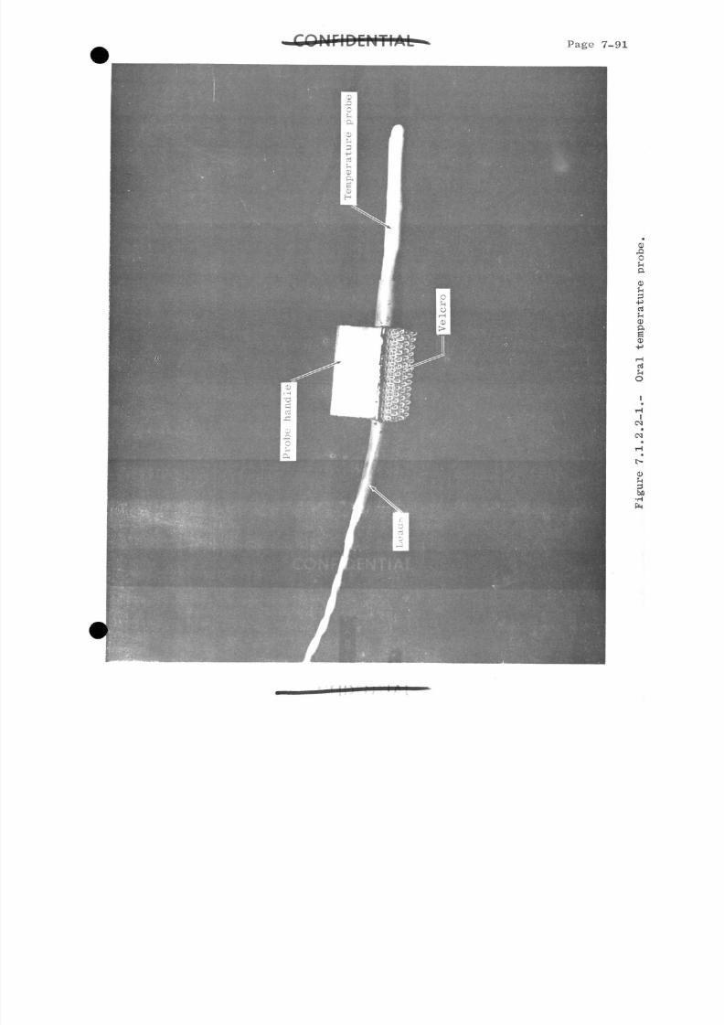
8/7/2019 Post Launch Memorandum Report for Mercury-Atlas No. 9(MA-9). Part 1 Mission Analysis
http://slidepdf.com/reader/full/post-launch-memorandum-report-for-mercury-atlas-no-9ma-9-part-1-mission 252/344
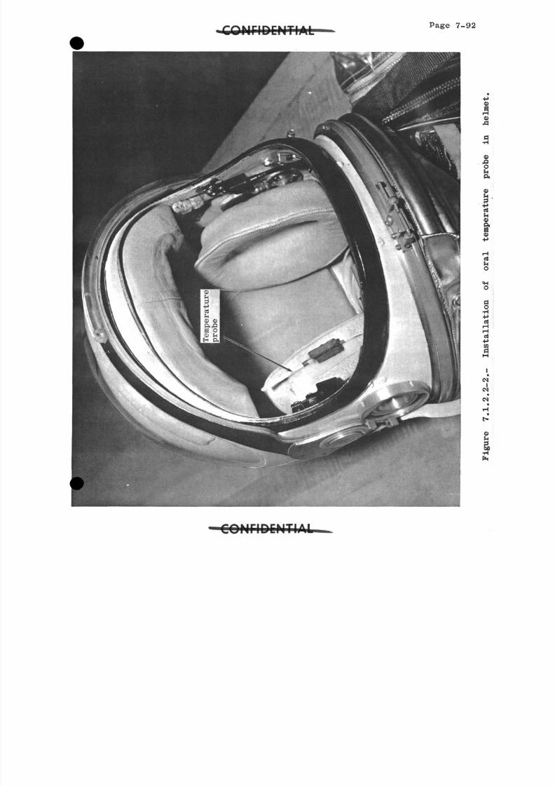
8/7/2019 Post Launch Memorandum Report for Mercury-Atlas No. 9(MA-9). Part 1 Mission Analysis
http://slidepdf.com/reader/full/post-launch-memorandum-report-for-mercury-atlas-no-9ma-9-part-1-mission 253/344
Page 7-9
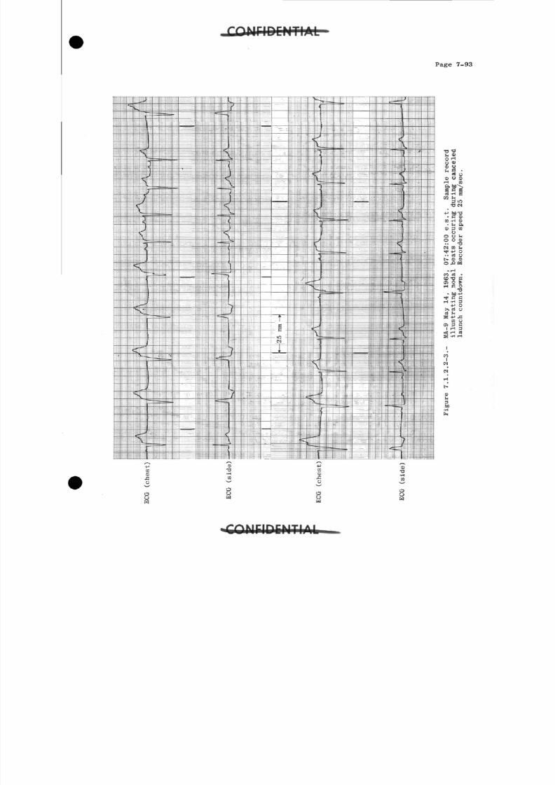
8/7/2019 Post Launch Memorandum Report for Mercury-Atlas No. 9(MA-9). Part 1 Mission Analysis
http://slidepdf.com/reader/full/post-launch-memorandum-report-for-mercury-atlas-no-9ma-9-part-1-mission 254/344
Page 7-93
< n< D&o
0)•a
•p
Io
•a•H
w
I ir\FKITIA I
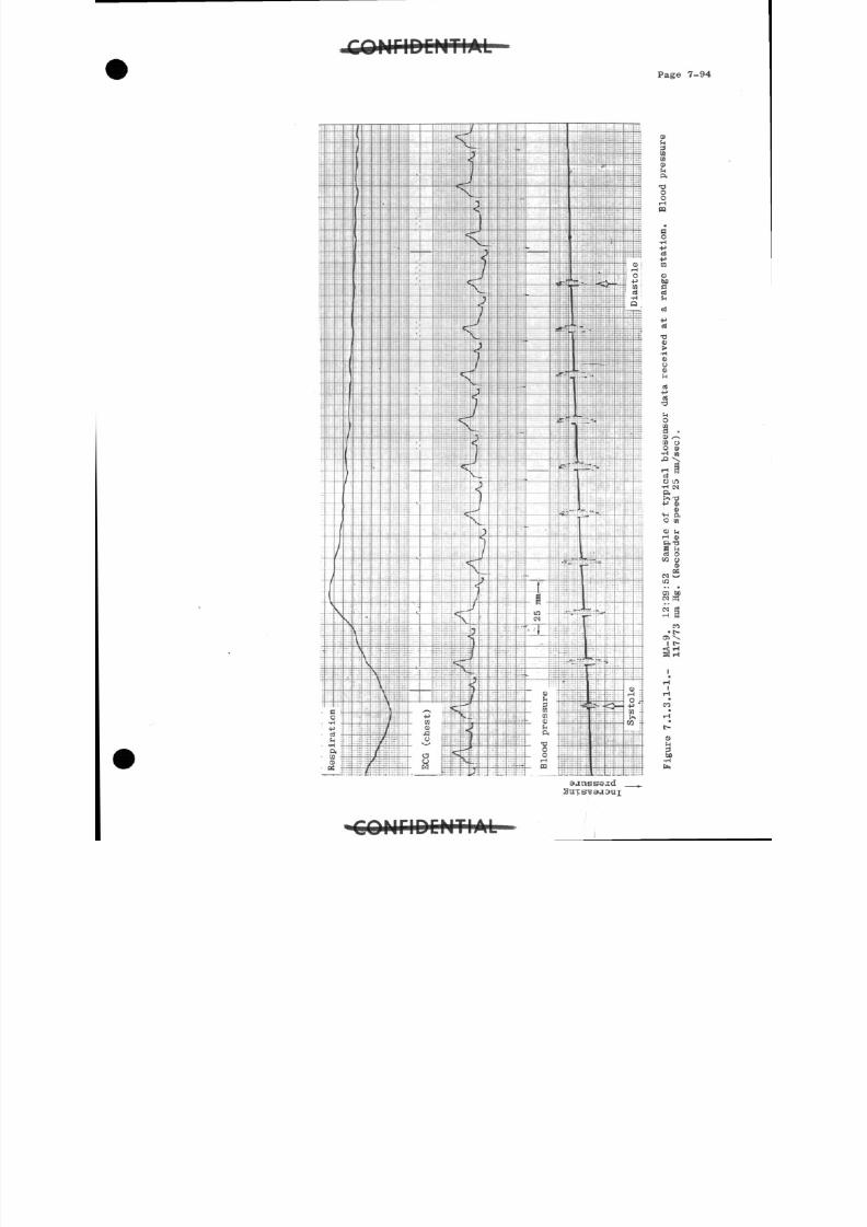
8/7/2019 Post Launch Memorandum Report for Mercury-Atlas No. 9(MA-9). Part 1 Mission Analysis
http://slidepdf.com/reader/full/post-launch-memorandum-report-for-mercury-atlas-no-9ma-9-part-1-mission 255/344
Page 7-94
•ooo
o >M
O S
a
-p
730)
•H< DO0)
a•o
Oma •O x^10 oO 0)•H 01
ciO lO•H INO.>>•&+j m
o•H ao en
O i-irH fl>P.T3S hrt o
W O0!K
N v^in
0> boN B5
C1• t-
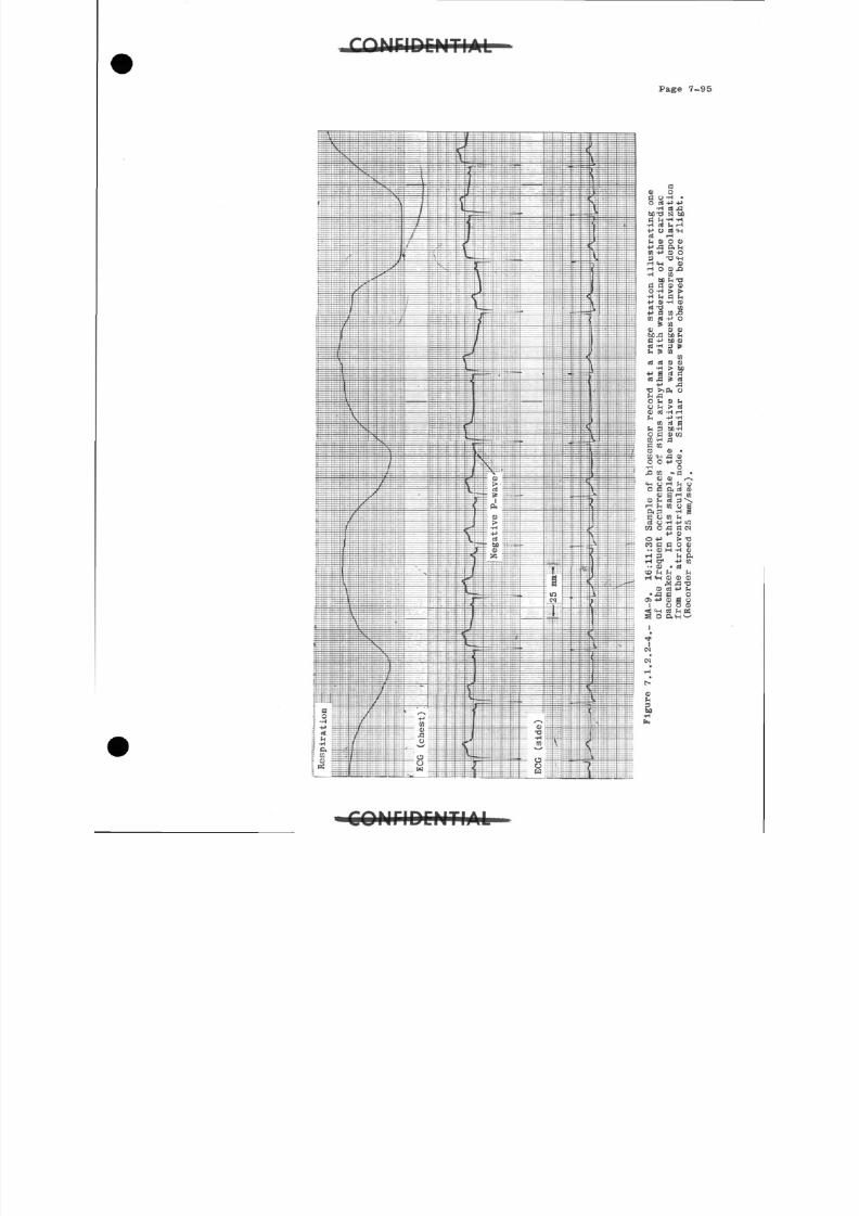
8/7/2019 Post Launch Memorandum Report for Mercury-Atlas No. 9(MA-9). Part 1 Mission Analysis
http://slidepdf.com/reader/full/post-launch-memorandum-report-for-mercury-atlas-no-9ma-9-part-1-mission 256/344
Page 7-95
a0 oa o -H •o a 4 -> -p
•H CS Sit o - d IS) SBa i* -H -H•H 01 t, rH
•P O e« IHCli iHt* 0 O »•P J3 P. SH
3 T3 <HrH <H CD
iH O 0 ja•rt U!
Mh 73
a a 0 0O -H > >•H h a IH•P 0 -H 0d-d (0
•p a to arao j v o3 in0 00
a -P SB 0rt -H 3 &h 6
ind d CD o
•H > to•p a d an A P cd
P JST3 XQ, O
Oh 0 h
O > rt0 rt -H rHh +J -H
10 «l 8h 3 bB-Ho a 0 raM -H aa inC D 0 •C O <H J3 0O O P T3•H O
00 /-s"M O H h OO a On rt 0
0 S iH 010 P rt 3\
IH h in o aft 3 -H aa o ra 3 o -H p uira o * a IN
•p 0
n a a o 0•• 0 M H 0
H 3 H P.HC T +• in••0 • d
CD ^H 5n h
r-l <H V 0 0^ J3T3
0 a -p ^•fl S O
o > -P 0 8 o1 O O 0
«! <H <S hCH3 OP.H'
C Q N r i D C M T I A L
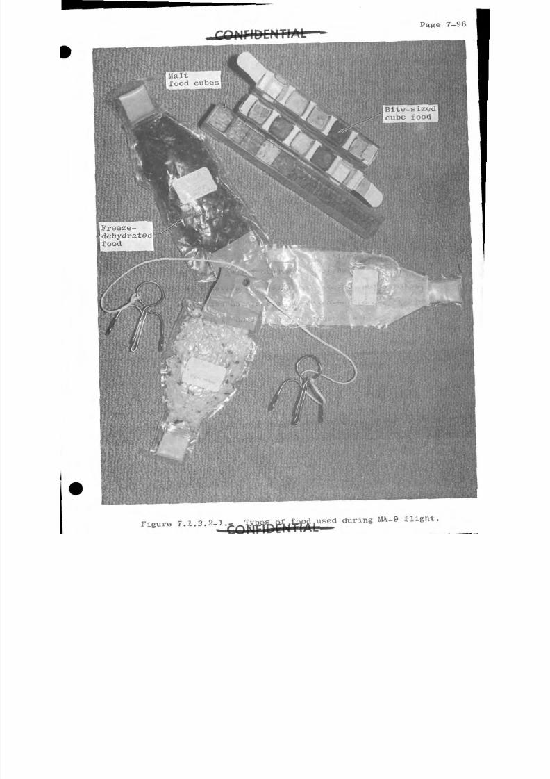
8/7/2019 Post Launch Memorandum Report for Mercury-Atlas No. 9(MA-9). Part 1 Mission Analysis
http://slidepdf.com/reader/full/post-launch-memorandum-report-for-mercury-atlas-no-9ma-9-part-1-mission 257/344
Page
-
zit
ood c u ~ e s - 71 'b
3eze-
h y d r a tnd
F i g u r e 7.1.3.2-1.-u s e d d u r i n g MA-9 f l i g h t *
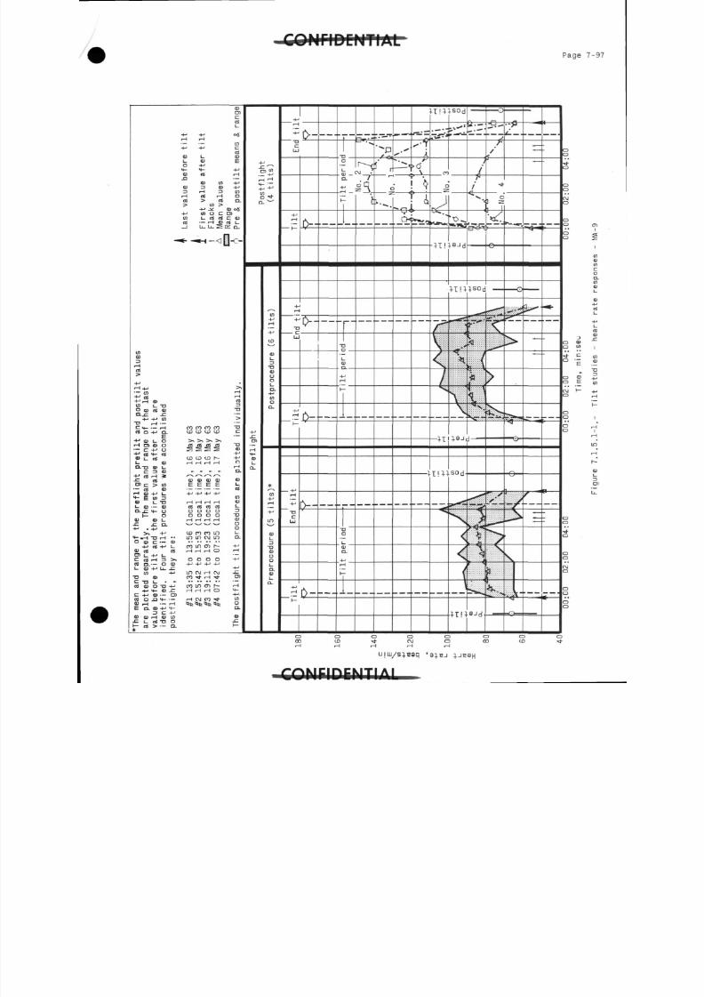
8/7/2019 Post Launch Memorandum Report for Mercury-Atlas No. 9(MA-9). Part 1 Mission Analysis
http://slidepdf.com/reader/full/post-launch-memorandum-report-for-mercury-atlas-no-9ma-9-part-1-mission 258/344
C Q U C I D C N T I A LP a g e 7 - 9
aC D
<D!_
01
_ MslJJHCMT1AI
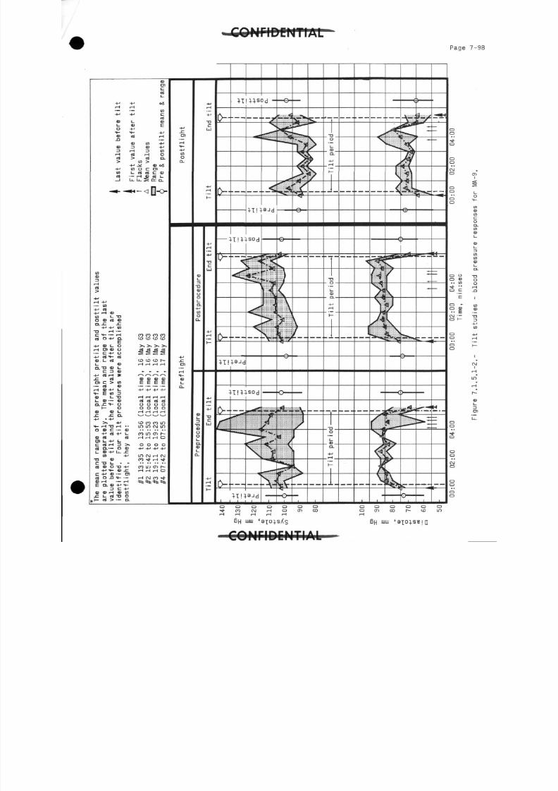
8/7/2019 Post Launch Memorandum Report for Mercury-Atlas No. 9(MA-9). Part 1 Mission Analysis
http://slidepdf.com/reader/full/post-launch-memorandum-report-for-mercury-atlas-no-9ma-9-part-1-mission 259/344
P a g e 7
T
r
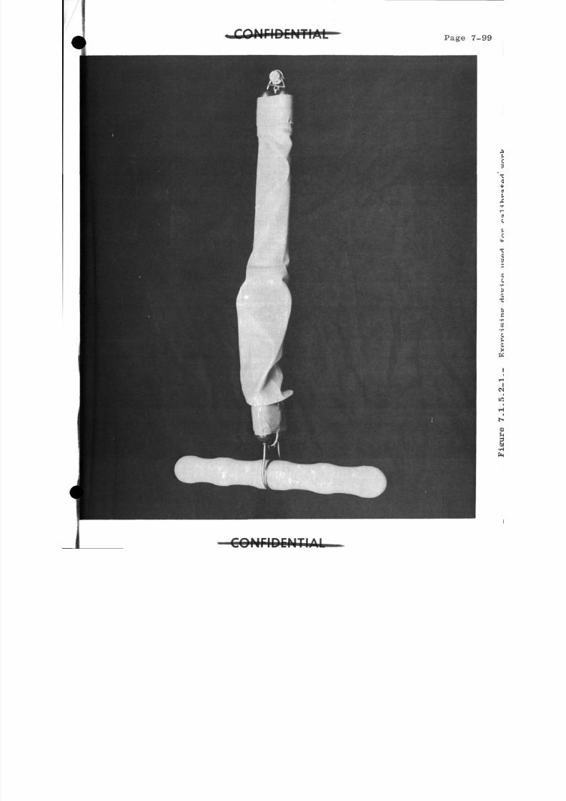
8/7/2019 Post Launch Memorandum Report for Mercury-Atlas No. 9(MA-9). Part 1 Mission Analysis
http://slidepdf.com/reader/full/post-launch-memorandum-report-for-mercury-atlas-no-9ma-9-part-1-mission 260/344
Page 7-
AI
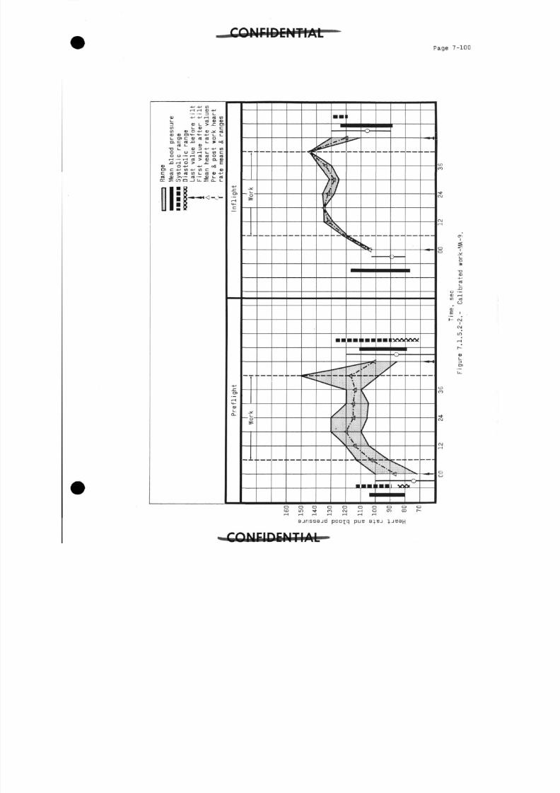
8/7/2019 Post Launch Memorandum Report for Mercury-Atlas No. 9(MA-9). Part 1 Mission Analysis
http://slidepdf.com/reader/full/post-launch-memorandum-report-for-mercury-atlas-no-9ma-9-part-1-mission 261/344
P a g e 7-100
tni
<z
-nc u
re!_
-Q
OS
CJ
CM
CM
IT)
it
r-
<D
ajnssajd p o o - [ q P U B
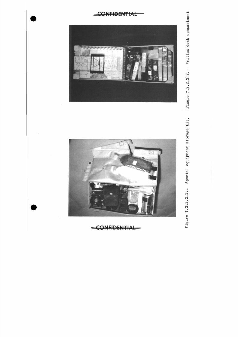
8/7/2019 Post Launch Memorandum Report for Mercury-Atlas No. 9(MA-9). Part 1 Mission Analysis
http://slidepdf.com/reader/full/post-launch-memorandum-report-for-mercury-atlas-no-9ma-9-part-1-mission 262/344
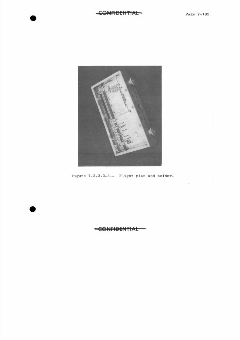
8/7/2019 Post Launch Memorandum Report for Mercury-Atlas No. 9(MA-9). Part 1 Mission Analysis
http://slidepdf.com/reader/full/post-launch-memorandum-report-for-mercury-atlas-no-9ma-9-part-1-mission 263/344
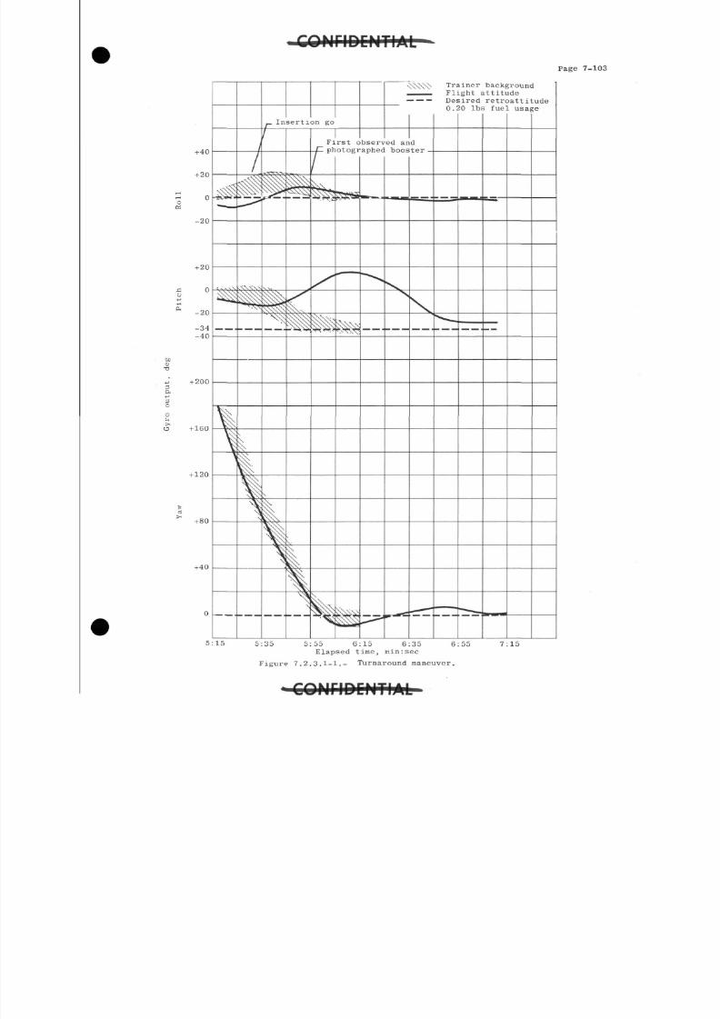
8/7/2019 Post Launch Memorandum Report for Mercury-Atlas No. 9(MA-9). Part 1 Mission Analysis
http://slidepdf.com/reader/full/post-launch-memorandum-report-for-mercury-atlas-no-9ma-9-part-1-mission 264/344
C O N F I D E N T I A L
Page 7-103
+40
+ 20
cOS
-20
+ 20
o-P•H
Q ,-20
-34-40
ito
•o
3ft
+ 200
+ 160
+120
Itx
+ 80
+ 40
5:15
f
Insertion go
r
\SSSS> Trainer background^__ Flight attitude
Desired retroattitude0.20 Ibs fuel usage
First observed an dphotographed booster
5:35 5:55 6:15 6:35Elapsed time, min:sec
Figure 7.2.3.1-1.- Turnaround maneuver.
6:55 7:15
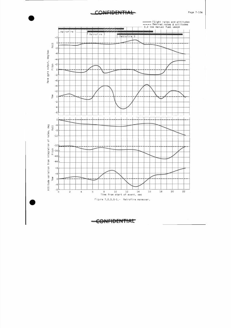
8/7/2019 Post Launch Memorandum Report for Mercury-Atlas No. 9(MA-9). Part 1 Mission Analysis
http://slidepdf.com/reader/full/post-launch-memorandum-report-for-mercury-atlas-no-9ma-9-part-1-mission 265/344
I r^i-i. 1Page 7
+ 2
^ 0i t
O
K -2
- 4
+ 4
•c +2o
o l 0
*6
+ 4
* 0
-2
- 4
- 6
-Retrof r e I ,
' Retrof r eRetrof i r e
F l i g h t rates a n d attitudesD e s i r e d rates & a t t i t u d e s
• 3.2 Ibs manual fuel usage
z
° = -8
-12
-32
3-36
'^-40
-44
+8
7
- 4
- 8
\
8 10 12 14
T i m e from start o f event, s e c
16 18 20 22
F i g u r e 7.2.3.5-1.- R e t r o f i r e maneuver.
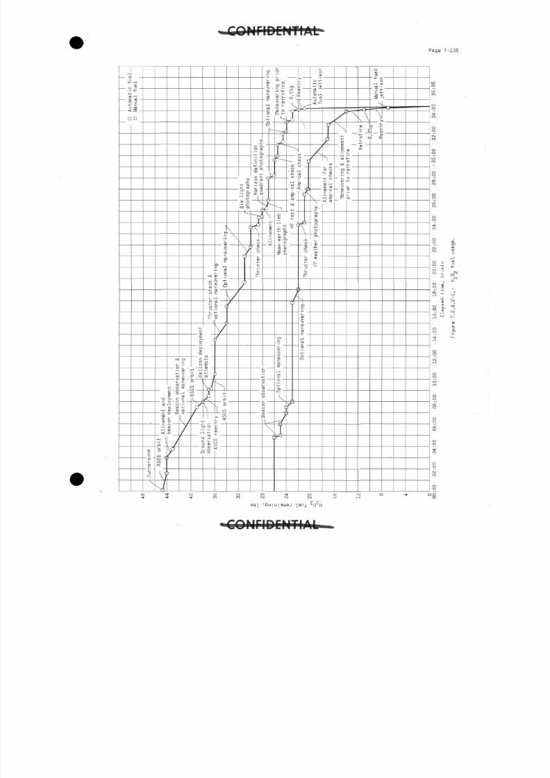
8/7/2019 Post Launch Memorandum Report for Mercury-Atlas No. 9(MA-9). Part 1 Mission Analysis
http://slidepdf.com/reader/full/post-launch-memorandum-report-for-mercury-atlas-no-9ma-9-part-1-mission 266/344
P a g e 7-105
A . i
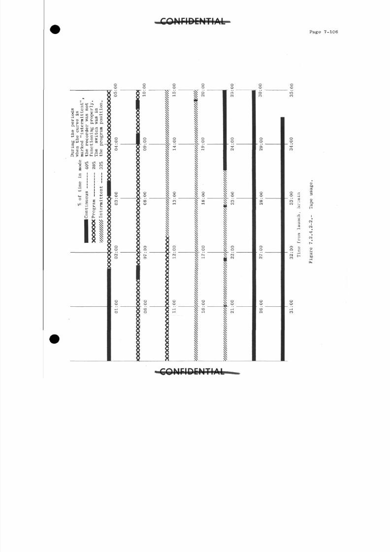
8/7/2019 Post Launch Memorandum Report for Mercury-Atlas No. 9(MA-9). Part 1 Mission Analysis
http://slidepdf.com/reader/full/post-launch-memorandum-report-for-mercury-atlas-no-9ma-9-part-1-mission 267/344
TIA i
Page 7-1
o f
5 36 CD
P.h rt
orf+H
0)
CS 1I
CM
IPvCklTlAl
8/7/2019 Post Launch Memorandum Report for Mercury-Atlas No. 9(MA-9). Part 1 Mission Analysis
http://slidepdf.com/reader/full/post-launch-memorandum-report-for-mercury-atlas-no-9ma-9-part-1-mission 268/344
-JCyWWftfimTMT* Page 8-1
8.0 FLIGHT CONTROL AND NETWORK PERFORMANCE
8.1 Flight Control Summary
8.1.1 Prelaunch operations.- The Mercury Control Center (MCC) and
Bermuda (BDA) flight controllers were deployed for the MA-9
mission on April 30, 19^3. The remainder of the flight con-
trol teams began to deploy on May 2, and all teams had " b e e n
deployed by May 5, 196j. The MCC-BDA flight control teamswere exercised through a series of 10 launch simulations.
These simulations exercised the decision capability of the
flight controllers and the astronaut during the criticalpowered-flight phase of the mission.
Four days of network simulations were conducted in prepara-
tion for the mission. The exercises performed on May 1, 8,
and 9 involved two simulations daily. The final networksimulation was performed on May 12, 1963. At the completion
of this exercise, the network and the flight control teamshad reached a satisfactory state of readiness and were ready
to support the scheduled flight.
Because of the extended flight duration, an additional flightcontroller was assigned to the flight control teams at both
Kano, Nigeria (KNO) and Zanzibar (ZZB). The Kauai Island,Hawaii (HAW) site was supported by two complete flight con-
trol teams, because of the frequency of its contact periods.
Several new flight controllers were used, primarily at BDA,
ZZB, Rose Knot Victor command ship (RKV), and HAW. The CorpusChristi, Texas (TEX) site was again used as a training facil-
ity for the mission. Five aeromedical monitors and five
procedures-trainer personnel from the Flight Crew Operations
Division participated in the simulations at this site.
The Mercury Control Center was manned on a two-shift basis.
The shift changeover occurred approximately every 8 hours
throughout the flight. The flight control countdown was in-
itiated by the second shift team at T-215 minutes. The first
shift was on duty at T-120 minutes. Both shifts were on dutyfor the launch and reentry phases of the mission.
The flight control documentation for the MA-9 mission was sat-
isfactory. A total of 3^ Instrumentation Support Instructionswas transmitted to the network. The majority of these docu-
ments required only one revision during the prelaunch period.The only major revisions required were those to the instrument
calibration curves. These changes were necessary because of
calibration shifts and are normally transmitted after the launch-
pad tests, conducted 4 days prior to lift-off. Other minor
8/7/2019 Post Launch Memorandum Report for Mercury-Atlas No. 9(MA-9). Part 1 Mission Analysis
http://slidepdf.com/reader/full/post-launch-memorandum-report-for-mercury-atlas-no-9ma-9-part-1-mission 269/344
8/7/2019 Post Launch Memorandum Report for Mercury-Atlas No. 9(MA-9). Part 1 Mission Analysis
http://slidepdf.com/reader/full/post-launch-memorandum-report-for-mercury-atlas-no-9ma-9-part-1-mission 270/344
Page 8-3
data channel and the shift register in the range digital data
channel. The simultaneous failure of both components compli-
cated an effective failure analysis and caused the earlier
difficulties in solving the problems.
At 4:00 p.m.e.s.t. it was decided that the BDA FPS-16 radar
system would be able to support the launch and that the count-
down for the second launch attempt would be initiated the
following day.
The countdown was recycled for 24 hours, and the network count-
down was resumed at 2:00 a.m.e.s.t. on May 15, 19&3- All
primary network systems, with minor exceptions, were operable
when the countdown was initiated.
The confidence summaries transmitted by the network to verify
the site and calibrations were very good. No major discrepan-
cies were noted in the network voice communications. However,
the ZZB, Canton Island (CTN), RKV,and Coastal Sentry Quebec (CS
sites were influenced by propagation, and several repeats were
required from the stations. The ships were serviced by two
diverse radio links. The CSQ communications were routed through
New York and Honolulu. In most cases, these different paths
allowed communications to the ships during the periods ofday-
night frequency transition. The sites suffered short-duration
dropouts on the voice links throughout the test; however,
communications were quickly reestablished.
This countdown was continuous, except for a short hold for the
launch-vehicle ground support equipment at T-llminutes 30 sec-onds. The countdown was resumed within approximately 4 minutes
and lift-off occurred at 8:04:13 a.m.e.s.t.
8.1.3 Powered flight.- The powered flight phase was normal and all
launch events occurred at nearly the expected time. The guidanc
and data systems performance was excellent. All data sources
provided good, consistent data. Sustainer engine cut-off occurr
at 00:05:02.9 at a space-fixed velocity of 25,735 ft/sec. The
flight-path angle at cut-off was +0.00321°. A "go"condition
was evident at insertion, and the orbit lifetime was notcon-
sidered to be a problem. All spacecraft and launch-vehicle
systems performed satisfactorily during the launch phase, andthe air-ground communications were somewhat better than those
in previous missions.
8.1.4 Orbital flight.- After spacecraft separation, the astronaut
performed a fly-by-wire (ZBW) turnaround maneuver. Shortly
after completion of this maneuver, the BDA capsule communica-
tor (Cap Com)advised the MCC that an approximate 6° rise in
C O N F I D C H T I A L " -
8/7/2019 Post Launch Memorandum Report for Mercury-Atlas No. 9(MA-9). Part 1 Mission Analysis
http://slidepdf.com/reader/full/post-launch-memorandum-report-for-mercury-atlas-no-9ma-9-part-1-mission 271/344
Page 8 -
• -»**»*- " - . • • - - • . . . . tttfg.f.,
CONFIDENTIAL
c a ~ b i n - and suit-dome heat-exchanger temperatures had been
observed on telemetry at BDA. The astronaut was appraisedof this situation and increased the coolant flow. At space-craft loss of signal with BDA, the dome temperatures hadstabilized. When the astronaut acquired communications with
the Canary Islands (CYl), he said that the dome-temperaturewarning light was on. This warning indication was causedby the suit dome temperature decreasing below 51° F. Theastronaut was required to monitor this temperature through-out the flight and make frequent adjustments to the coolantcontrol valve. As a result of the exit heat pulse, thecabin temperature indication on telemetry rose from 9 -° Fat launch to approximately 118° F when the spacecraft was overMuchea, Australia (MUG). Subsequently, this temperature de-creased slowly to a value between 90° F and 100° F. Thecabin-air temperature appeared to vary slightly as a functionof the spacecraft a-c power usage. During the periods in
which the automatic stabilization and control system (ASCS)115 v a-c inverter was being used, the temperature would riseto a value of between 97° F and 105° F; and when this inverterwas not being used, the temperature would apparently decreaseslowly over a period of two passes to a value of between90° F and 97° F. All spacecraft systems were functioningnormally, and the MCC advised the Guaymas, Mexico (GYM) siteto transmit a "go" decision for seven orbital passes to theastronaut.
The first minor discrepancy occurred over MCC at the beginningof the second orbital pass. When the telemetry was commanded
by the ground, a series of repetitive R- and Z-calibrationsoccurred. It was decided that the programed R and Z calibra-tion function would be turned off during the sleep period.This anamoly occurred again when the C-band beacon wascommanded "on" over MCC at the beginning of the l6th orbitalpass.
The flashing beacon was deployed at 03: 5:00. The astronautreported that he felt the beacon deploy; however, he did notsee the light during its first night period. The astronaut
All instrumentation values presented in this section werederived in real time over telemetry, unless otherwise stated.
8/7/2019 Post Launch Memorandum Report for Mercury-Atlas No. 9(MA-9). Part 1 Mission Analysis
http://slidepdf.com/reader/full/post-launch-memorandum-report-for-mercury-atlas-no-9ma-9-part-1-mission 272/344
Page 8-5
verified that the attitudes and time were correct for deploy-ment of the beacon. The "beacon was observed during sunsetof the 4th orbital pass~"and was tracked during the night per-iod of that pass. All systems continued to perform satis-factorily. However, the astronaut was required to makefrequent changes to the suit coolant control valves in order
to maintain the suit heat-exchanger dome temperature withinlimits.
At the beginning of the 5th orbital pass, the astronautturned the cabin fan and cabin heat exchanger off as scheduledby the flight plan. It was noted subsequently that turningoff the cabin fan while in a powered-down condition did notmaterially affect the cabin temperature. The astronaut openedthe outlet port of the condensate trap in accordance with hisflight plan.
It was noted early in the flight that the actual power usage
was slightly less than predicted. This condition resulted inallowing for more radar beacon tracking during the later phasesof the flight. The C-band beacon was turned on three timesprior to passes over the HAW station to enable tracking by theRange Tracker ship. Attitude-control-fuel usage was also lessthan expected, and all reports indicated that the astronautwas managing his fuel supplies exceptionally well.
The astronaut made two attempts to deploy the balloon for theballoon drag and visibility experiment, starting at 09:00:00.All attempts were unsuccessful; and based upon analysis ofthe system and the undesirability of powering up the squibbus, it was decided that no further attempts would be made todeploy the balloon. The astronaut was advised not to actuatethe jettison switch.
During the 7th pass at 10:02:00, MCC directed ZZB to transmitto the astronaut a "go" decision to continue for 17 orbitalpasses. At this time all systems were performing well. Ingeneral, the usage of consumables was better than expectedand the astronaut was in excellent condition. Because of theexcellent performance of the astronaut and the spacecraftsystems, the task of flight control was one of monitoring
systems performance, gathering and transmitting summary infor-mation, and assisting the astronaut in carrying out his flightplan.
At the end of the 7~th pass the astronaut powered down the ASCSbus over the CSQ and began a period of extended drifting flightAt this time he stated that he was perspiring lightly and that
8/7/2019 Post Launch Memorandum Report for Mercury-Atlas No. 9(MA-9). Part 1 Mission Analysis
http://slidepdf.com/reader/full/post-launch-memorandum-report-for-mercury-atlas-no-9ma-9-part-1-mission 273/344
n fPage 8-6
he was continuing to monitor the suit dome temperature.Occasionally, the ground stations became concerned becauseof the gradual temperature increase apparent in the cabin-
heat-exchanger dome temperature. This measurement wasexpected to reach ambient eventually, but it stabilized at
approximately 75° F. The HAW site obtained good trackingon the C-band beacon on the 7th pass, and these datacon-firmed the nominal orbit. All scheduled radar tracking duringthe orbital phase was good and the acquisition and retrofiretimes were near nominal throughout the entire flight.
The RKV received a readout of the major onboard parametersfrom the astronaut at 12:28:00, and the astronaut turned thetelemetry to continuous in preparation for the sleep period.The astronaut performed a checkout of the manual and fly-by-wire (FEW) thrusters. He reported to the CSQ at 13:30:00that the system was performing satisfactorily and that he hadjust been sitting quietly looking out the window. He thenindicated that he was ready to sleep. The network sites wereadvised that the sleep period had started, and that they wereto maintain air-ground communications silence unless telemetrysignals indicated that the astronaut should be contacted.Throughout the sleep period, all parameters indicated normalsystems operation. The suit dome temperature reading receivedat the KNO site changed abruptly. The change indicated thatthe astronaut had adjusted his suit coolant flow in order tomaintain the dome temperature within the limits. The aero-medical parameters which were monitored by the remote sites
indicated that the astronaut was sleeping. The respirationrate was holding fairly steadily at 15 breaths per minute,and the heart rate was steady, at approximately 60 beats perminute. During the llth pass, the MCC received electrocardio-gram (EGG) data, remoted from the Ascension Island; and asudden increase in the heart rate from 60 beats per minute to110 beats per minute was noted. The heart rate then decreasedto 70 beats per minute. These data were interpreted by theaeromedical monitors to indicate that the astronaut may havebeen dreaming. During the llth through l4th passes, theindicated automatic fuel quantity decreased from 82 percentto 75 percent. This change initially caused some concern,
but, after evaluation it was attributed to temperature stabi-lization effects, the normal nitrogen bottle leakage rate,and the readout accuracy of the ground telemetry for automaticfuel quantity.
During the l^th pass at 21:23:00, the MUG site received a re-port on consumables from the astronaut. The astronaut stated
C O M r i D E H T l A L
8/7/2019 Post Launch Memorandum Report for Mercury-Atlas No. 9(MA-9). Part 1 Mission Analysis
http://slidepdf.com/reader/full/post-launch-memorandum-report-for-mercury-atlas-no-9ma-9-part-1-mission 274/344
8/7/2019 Post Launch Memorandum Report for Mercury-Atlas No. 9(MA-9). Part 1 Mission Analysis
http://slidepdf.com/reader/full/post-launch-memorandum-report-for-mercury-atlas-no-9ma-9-part-1-mission 275/344
Page 8 -
not yet completed, it was generally thought that the gyros,
attitude indicators,, and scanners were inoperative and that the
0.05g circuit was latched up. At this time it was realized
that a manual retrofire would be required and that a check-
list would have to be prepared for the astronaut.
At approximately 30:00:00 the remote site flight control
personnel that were on standby status were recalled to their
stations, and they were advised to stand by to attempt to
relay communications to the astronaut if directed by MCC.
While he was in contact with the CSQ, the astronaut was
requested to turn on the telemetry and the C-band beacon in
order that the Range Tracker could make a check of its radar
data, since this ship was the prime station for reentry
tracking. These data were even more important since the
retrofire maneuver would be performed manually. During the
time interval between loss of signal with MCC on the 20th pass
and acquisition of communications with HAW on this pass, addi-
tional tests were devised to verify where the ASCS logic was
latched up. As the spacecraft passed over HAW, the astronaut
was requested to place the ASCS 0.05g and emergency 0.05g fuse
switches in the on position and to select the ASCS automatic
mode to verify the 0.05g event. If the spacecraft began to
roll as it would normally do if 0.05g indications were valid,
the ASCS was latched in to the reentry mode. The astronaut
verified this roll rate, and the 0.05g event was confirmed
by telemetry over the GYM site. At this point the flight
controllers knew the configuration of the ASCS logic and
the required configuration for reentry. After completion
of this test, it was determined that the ASCS would provide
proper attitude control and roll rate for reentry.
Prior to the astronaut's acquiring communications with the
CSQ on the 21st pass, a manual retrofire checklist was com-
pleted and thoroughly checked out by MCC. This checklist
was sent via TWX to ZZB, CSQ, and HAW, and its receipt was
acknowledged. The checklist was as follows:
A. Primary procedure for retrofire
1. Attitude permission by-pass
2. Retrorocket arm switch, manual
3. Fly-by-wire thrust select switch, high and low
4. Retrosequence fuse switch, number 2
8/7/2019 Post Launch Memorandum Report for Mercury-Atlas No. 9(MA-9). Part 1 Mission Analysis
http://slidepdf.com/reader/full/post-launch-memorandum-report-for-mercury-atlas-no-9ma-9-part-1-mission 276/344
Page 8-9
5- Retrofire manual fuse switch, number 2
6. ASCS a-c bus switch, on
T. ASCS 0.05g fuse switch, number 1
8. ASCS control switch, select
9 - Mode select switch, off
10. Manual handle, push on
11. Squib arm at retrofire minus 5 seconds
12. Countdown to retrofire
IJ. Depress fire retro override at retrofire time
B. Backup to be used if there is no retrofire
1. Retro delay to instant
2. Depress retrosequence button
C. Additional precautions
1. Retropackage jettison will have to be manual.
Be sure not to arm the retropackage jettison
switch until after the rockets are fired.
2. Astronaut probably will not get a fire retro
telelite
D. Hold retroattitude and jettison retro, keep ratesas low as possible while maintaining usual referenceas an aid for low rates and at the nominal 0.05g time
(3 :09:19); select reentry mode.
E. At correct 0.05g time, select automatic on the ASCScontinuous switch.
In addition to the checklist which was relayed to the space-craft and written down by the astronaut, the CSQ attemptedto reset the clock by a ground command. The desired clocksetting for the time of retrofire was 3^ hours 59 minutes and52 seconds.
The desired time of retrofire was 33:59:30. The differencebetween the clock setting and the desired time of retrofire
8/7/2019 Post Launch Memorandum Report for Mercury-Atlas No. 9(MA-9). Part 1 Mission Analysis
http://slidepdf.com/reader/full/post-launch-memorandum-report-for-mercury-atlas-no-9ma-9-part-1-mission 277/344
- 10
resulted from a correction for the predicted clock error
which would be 22 seconds fast at time of retrofire. Also
since the clock was not to be used for retrosequence, only
the minutes and seconds needed to be accurate for the astro-
naut's reference and the clock setting advanced 1 hour to
avoid possible clock timeout. This command was not set into
the clock, but the astronaut successfully reset the clock.
The telemetry and G-band beacon were again turned on for the
Range Tracker as the spacecraft passed over the CSQ.
The astronaut was advised to "take green for go, " which was
a coded means of telling him to take a dextro amphetamine
pill. The pill was used as an added precaution to be sure
that the astronaut was alert for the retrofire maneuver.
The flight surgeon was not concerned over the astronaut's
condition but he was not sure the astronaut was thoroughly
rested from his sleep. The ZZB site noted a rise in carbon
dioxide partial pressure (PCCu) and the astronaut was advised
to purge the suit circuit with fresh oxygen by going on
0 emergency rate flow. A quick estimate of the quantity ofd
1oxygen remaining indicated that Ip- hours of 0 emergency rate
flow was available. The ZZB capsule communicator confirmed
each item on the checklist with the astronaut and he verified
that all items on the list were completed with the exception
of arming the squib switch.
Two additional items were added to the checklist at this
time. The first was to be sure that the visor was closed,and the second was to cage the gyros.
For the first time, the astronaut reported to ZZB that the
main and standby 250 v-amp inverters had failed to operate.
At this point, MCC advised ZZB to turn the ASCS a-c switch
to off, because the inoperative power circuit would require
the entire reentry to be manually controlled.
The CSQ acquired communication with the spacecraft at 33:56:5^--
The capsule communicator and the astronaut reviewed the retro-
fire and reentry procedures and it was apparent that the
astronaut was prepared for his task. Time hacks were trans-mitted to the astronaut at retrofire time minus 60 seconds
and at retrofire time minus 30 seconds. Finally, a 10-second
terminal countdown to retrofire was transmitted. The squib
bus was armed at retrofire minus 5 seconds. The number one
retrorocket was ignited at 33:59:30 and ignition of retro-
rockets number two and three occurred at the proper 5-second

8/7/2019 Post Launch Memorandum Report for Mercury-Atlas No. 9(MA-9). Part 1 Mission Analysis
http://slidepdf.com/reader/full/post-launch-memorandum-report-for-mercury-atlas-no-9ma-9-part-1-mission 278/344
Page 8-11
intervals. The telemetry data immediately confirmed the
retrofire. The astronaut stated that his attitudes were
good and confirmed the ignition of the three retrorockets.
The retropackage was manually jettisoned at approximately
3 :00:43. Communications were good through loss of signal
with CSQ. The "beginning of the reentry blackout was re-
ported by the Range Tracker to be within 2 seconds of the
time predicted, which indicated that the landing point would
be close to nominal. Communications were regained by the
HAW capsule communicator via the relay aircraft at approxi-
mately 3 -:20:30. The weather in the recovery area was good.
The final landing point was only about 4 miles from nominal.
8.2.7 General Comments.- The network flight control teamsper-
formed extremely well. Communications between the ground
and the astronaut were concise and they conveyed thenec-
essary information. The flight control teams utilized the
proper contact and reporting procedures that were developed
for this mission. The network data as presented on the
summary messages appeared, in most cases, to have an accuracy
within 2 percent. The operations messages provided muchuse-
ful real-time data, and no difficulty existed in determining
the precise status of the spacecraft, the astronaut, and the
mission.
The ground communications were generally good; however, those
at the ZZB and CSQ sites were not as good as those from the
rest of the network. The air-ground communications as
monitored on the Goddard loop were somewhat better than in
previous missions and probably resulted from the use of
squelch control at the remote sites. The air-ground com-
munications as remoted through the HAW site were good;how-
ever, two transmitters at the HAW site failed.
The entire mission was an extremely smooth and well coordinated
effort. The preflight network simulation exercises were the
best planned and executed to date. The flight controllers
response was very good, and it is felt that this test was
the best executed mission or Project Mercury. The cooperation
between the flight astronaut and flight control personnel had
a significant influence on the success of the MA-9mission.
CQNriDEMTIAlr
8/7/2019 Post Launch Memorandum Report for Mercury-Atlas No. 9(MA-9). Part 1 Mission Analysis
http://slidepdf.com/reader/full/post-launch-memorandum-report-for-mercury-atlas-no-9ma-9-part-1-mission 279/344
8/7/2019 Post Launch Memorandum Report for Mercury-Atlas No. 9(MA-9). Part 1 Mission Analysis
http://slidepdf.com/reader/full/post-launch-memorandum-report-for-mercury-atlas-no-9ma-9-part-1-mission 280/344
1DENTIAL Page 8 - 13
absence of equipment malfunctions during the longer duration of the
MA-9 mission, considering that sites were allowed to go to a standby
status at various times, is indicative of a high degree of excellence
in maintenance and operational procedures by all sites.
8.2.1 Computing and trajectory displays.- The network countdown for
the MA-9mission began at the Goddard Computing Center at
midnight on May 14. The Goddard computer, equipment, interface,
CADFISS, and trajectory confidence tests were all satisfactory.
During the countdown, some dropout in the Goddard "B" computer
readouts was observed at the MCC. The high-speed output
subchannel on the data communication channel for this computer
was interchanged with the plotboard high-speed subchannel.
At the request of the Flight Dynamics Officer, the powered-
flight- phase was supported with the "A" and "C" computers,
and then the support was switched to the "A" and "B" computers
during orbital flight. The "B" computer gave no indication
of dropout during the rest of the mission. Lift-off occurredat 08:04:13 a.m.e.s.t.
The Atlantic Missile Eange (AMR) I.P. 709 and the General
Electric - Burroughs computers provided excellent data
throughout the launch. A "go"decision was indicated by all
three data sources. The cut-off conditions are shown in
table 8.2.1-1.
In the orbital phase, during the periods when the spacecraft
C- and S-band beacons were on, the tracking data received
from the network sites were excellent. During the mission,
weight changes in the spacecraft resulting from fuel andcoolant-water usage were manually put into the computers.
The retrofire time recommended by the Goddard computers was
33:59:30, and retrofire was manually initiated at this time.
After retrofire, the predicted landing point transmitted to
the MCC from the Goddard computer was 27° 22' North latitude
and 176° 29' West longitude. An attempt to refine this
prediction with six frames of data from the Range Tracker
ship, acquired during blackout, failed to yield a converged
solution. The computed time of the blackout was from
3 :08:16 to 3V.22:30. The actual time of initial blackout
was reported by the Range Tracker to be 3 -:08:17« The actuallanding point was reported by the recovery ship to be
27° 22.6' North latitude and 176° 35-3' West longitude.
Although several minor computer problems were encountered and
corrected throughout the flight, at no time during the mission
did the computers fail to drive the digital displays and
plotboards at the MCC. In addition, performance of the high-
speed lines between Goddard and the MCC was excellent.
8/7/2019 Post Launch Memorandum Report for Mercury-Atlas No. 9(MA-9). Part 1 Mission Analysis
http://slidepdf.com/reader/full/post-launch-memorandum-report-for-mercury-atlas-no-9ma-9-part-1-mission 281/344
3 -
For the first time, CADFISS tests were conducted during the
mission to determine the operational status of major equipment
subsystems at network sites. These tests were considered
necessary since mandatory equipment at many sites was shut
down for prolonged periods of time when the spacecraft was out
of range. All of these tests were successfully supported by
the third Goddard computer while the other two Goddard
computers continued the operational support of the mission.
This flight was the first to be supported by a triplex computing
system and the IBM 709 computers.
Two range ships, the Range Tracker and the Twin Falls Victory,
were used to provide tracking data to the Goddard computers.
The Range Tracker provided good tracking data during the 7th,
20th, and 21st orbital passes. During reentry the Range Tracker
was poorly positioned with respect to the blackout zone and
provided only six frames of data for this phase of reentry.
An analysis of these data indicated a landing point which was
about-3° or 180 nautical miles away from the correct landing
point. Twin Falls Victory data readout was good on three passes.
East Island data appear to be unusable. Ascension Island data,
used for the first time in a Mercury mission, appear to be
satisfactory.
8.2.2 Command system.- The command system for the MA-9mission
operated in a satisfactory mariner, and the command control plan
was followed very closely throughout the mission. Several
malfunctions were noted at various sites, but command capability
was never lost by any site during the time in which the space-
craft was passing over that site. The command carrier "on"
indication from BDA to the MCC was delayed approximately
32 seconds on the first pass; however, it had no net effect on
the mission since the onboard command receiver signal strength
remained above the receiver threshold setting. A summary of
the command handover exercises is shown in table 8.2.2-1 and
a summary of command transmissions is shown in table 8.2.2-2.
8.2.2.1 Ground system: A preliminary evaluation of the data shows
that all command sites had very good command coverage during
each pass. Command coverage became reliable at slant ranges
varying from 300 to 950 nautical miles. This large variancewas caused by the change in spacecraft antenna orientation
while the spacecraft was in attitude-free drifting flight, the
trajectory of"the spacecraft over the site, and the transmitter
output power of the respective sites.
MCC, GBI, and San Salvador (SAL) provided commandcon-
trol coverage during launch. This coverage was provided
by the MCC low pover unit from lift-off to T+90 seconds,
by the MCC high power unit from T+90 seconds to
8/7/2019 Post Launch Memorandum Report for Mercury-Atlas No. 9(MA-9). Part 1 Mission Analysis
http://slidepdf.com/reader/full/post-launch-memorandum-report-for-mercury-atlas-no-9ma-9-part-1-mission 282/344
Page 8-15
seconds, and by the SAL high power unit from
T+245 seconds to T+3&0 seconds, at which time command control
was switched to BDA. This switch to BDA was performed at
00:05:58.350, but the command carrier "on" indication was not
received at MCC until 00:06:30.3 , a delay of 32 seconds.
An evaluation of the onboard receiver signal strength data
revealed that the ground transmitted carrier was being received
by the onboard system at a signal strength of 27.5 microvolts
from lift-off to 00:07:03. The ground-recorded telemetry
readout correlates well with the onboard recorded data. This
delay is considered to have been a function of the ground
remoting equipment and was not detrimental to command control
during the launch phase. Investigations are continuing to
determine the cause of this delay.
The command control handover plan was updated one time during
the mission. This change compensated for the slight variance
in the orbital trajectory over the 22 orbital passes and was
sent to the Coastal Sentry Quebec (CSQ)ship for the reentry
phase. All other times were nominal.
A total of 19 functions was transmitted from the command
stations. All of these functions were received onboard the
spacecraft with the exception of one telemetry "on"function
from Muchea (MUG) and the clock change from the CSQ. The
telemetry "on"command from MUG was not received because it
was transmitted when the spacecraft was out of range of the
600-watt ground transmitter. The clock change from the CSQ
was not received because the command tone was also sent before
the spacecraft was within range of the ground transmitter.The frequency monitor aircraft which was stationed in the
Pacific reported through the CSQ that they did not attempt
any transmissions on the command frequency during the orbital
passes monitored.
The following ground system malfunctions were experienced:
1. The Bermuda high-power transmitter came on with a
3-6-kw output but did not come up to full power and failed
over to low power at approximately 00:06:16. This failover
did not interrupt command control during this pass. Beam
voltage was low and was corrected in time to support the nextpass with full 10 kw-power output.
"Vailover is defined as failure of the primary system,
accompanied by automatic switching to standby system.
•
8/7/2019 Post Launch Memorandum Report for Mercury-Atlas No. 9(MA-9). Part 1 Mission Analysis
http://slidepdf.com/reader/full/post-launch-memorandum-report-for-mercury-atlas-no-9ma-9-part-1-mission 283/344
8 - 1 6
2. The RKV had an intermittent problem in the beam
power supply of the backup power amplifier, and at 09:24:47 it
was reported as being inoperative for the remainder of the
mission. The prime transmitter was used to support the remainder
of the mission.
3. At BDA the C-band beacon "on" command was on before
the command carrier came up at 22:08:00, giving a code fault.
The code fault was released after the command system was brought
up manually.
4. Guaymas (GYM) had an autotransformer failure in the
standby transmitter at 25:16:47, and the system was reported
as operative at 27:13:47.
8.2.2.2 Spacecraft command system: The spacecraft had only one command
receiver onboard during the MA-9mission. The threshold level
was intended to be set between 2.5 and 3 microvolts; however,
the receiver was capable of and did receive command functions
at a level of approximately 5-microvolt. The saturation
value of the receiver was 27-5 microvolts. The system operated
normally with the exception of spurious command carrier reception
at 03:35:00 to 03:38:00, 11:24:00 to 11:27:00, and 27:10:40 to
27:13:20. During the time period of 27:10:40 to 27:13:20,
eight functions, having a duration of approximately 2 seconds
each, were recorded on the onboard recorder. These functions
have yet to be identified; however, they were of such a nature
that they did not affect the mission. An investigation is inprogress to determine the exact cause of these recorded events.
The preliminary results tend to show that these signals were
generated outside the spacecraft and were not caused by internal
EF beat harmonics.
The effect of antenna orientation angle during drifting flight
was noticeable, as it had been during the MA-8 mission.
However, the signal strengths received were much better than
had been anticipated. The onboard system was capable of and
did receive functions whenever they were transmitted within
range of the ground transmitters.
8.2.3 Eadar tracking performance.- During the countdown on May l4,
1963, the radar at Bermuda failed to pass the CADFISS slew
tests. Digital data were intermittently of poor quality in
both the azimuth and range channels. Efforts to locate the
trouble were ineffective, and the quality of the data
gradually decreased. At T-15 minutes, the range data error
exceeded the tolerable limits, and at T-13 minutes the mission
CONFIDENTIAL
8/7/2019 Post Launch Memorandum Report for Mercury-Atlas No. 9(MA-9). Part 1 Mission Analysis
http://slidepdf.com/reader/full/post-launch-memorandum-report-for-mercury-atlas-no-9ma-9-part-1-mission 284/344
Page 8-17
was postponed. Subsequent trouble shooting revealed a
faulty preamplifier in the azimuth digital data channel and
a faulty shift register in the range digital data channel.
The simultaneous failure of both components complicated the
failure analysis. The radar was repaired at 2:00 p.m. e.s.t.
on May l4, 1963.
On launch day there were no radar problems, and the C- and
S-band beacon checks prior to launch indicated no beacon
problems. The network C-band radars tracked approximately
10 percent of the total mission time, which is 80 percent of
the total time that the C-band beacon was turned on. The
network S-band radars tracked 1.7 percent of the total mission
time, which is 36 percent of the total time that the S-band
beacon was turned on. The amount of radar data furnished to
the Goddard computers was of sufficient quality and quantity
to update the trajectories, and it was determined that the
orbital parameters did not decay an appreciable amount.
Initial tracking reports indicated that the C-band beacon
was not as good as it had been on previous missions because
of the heavier than usual modulation on the beacon replies.
The heavy modulation experienced by the MCC and BDA radars
during launch seemed to lessen as the mission progressed.
In addition to the normal Mercury Network radar sites, the
following sites were used for the MA-9 mission: Ascension
Island, East Island, Puerto Rico, and the radar ships Twin
Falls Victory and Range Tracker. Radar tracking data for all
sites are tabulated in tables 8.2.3-1 and 8.2.3-2.
8.2.4 Ground telemetry system performance.- The telemetry coverage
for the MA-9 mission was excellent as shown in table 8.2.4-1.
There were no major ground system failures, although some
coverage was lost because of the manual switching procedure
used onboard the spacecraft. In general, any deviation from
nominal coverage can be attributed to spacecraft attitude or
to the transmitter being turned off. The telemetry relay
circuits from Antigua, California, Bermuda, and Ascension
were satisfactory in all respects. During all passes over
these stations when telemetry antennas were radiating, data
were remoted to the MCC. During the third orbital pass, the
telemetry was switched to the high-frequency link prior to the
spacecraft's passing over Hawaii and remained on until it
was over the California site, at which time telemetry was
switched back to the low-frequency link. At all other times,
the telemetry remained on low frequency. No telemetry system
anomalies were noted during this period.
8/7/2019 Post Launch Memorandum Report for Mercury-Atlas No. 9(MA-9). Part 1 Mission Analysis
http://slidepdf.com/reader/full/post-launch-memorandum-report-for-mercury-atlas-no-9ma-9-part-1-mission 285/344
P a g e 8 - 18 C O N F I D E N T I A L
In general, the performance of the acquisition-aid systems
at all stations was satisfactory and comparable to that of
previous missions. Low-angle elevation tracking, "below
approximately 15% was accomplished manually because of
multipath conditions at most stations. The only major
acquisition-aid problem experienced during the mission was
on the CSQ where failure of the elevation antenna drive
system occurred prior to the 6th orbital pass. However, theantenna was positioned manually from the 6th through the
8th passes, and the malfunction in the drive system was corrected
in time for acquisition in the 9~th pass.
8.2.5 Air-to-ground communications.- During the MA-9 mission, the
air-to-ground communications were of good quality. The UHF
system was used as the primary communications system except
for the scheduled HF checks. During periods of communication,
UHF coverage varied only slightly from predicted acquisition
and loss times because of the nominal orbital trajectory.
As expected, air-to-ground communications could not be
established during the communications blackout period. An
Instrumentation Support Instruction was transmitted to the
network outlining the use of the UHF squelch circuit as defined
in the network documentation. A premission checkout and the
mission results indicate that proper use of the squelch
circuit eliminates background noise from open UHF receivers
during periods of silence. This change also resulted in a
reduction of noise level on the Goddard circuit during
air-to-ground transmissions.
The results of the ground HF antenna test, in which a
vertically polarized antenna replaced the normally used
horizontally polarized two-element beam, are inconclusive at
this time. The Kano station reported that the signal strength
received was lower when the vertically polarized antenna was
used than when the horizontally polarized antenna was used.
Texas reported higher signal strengths when the vertically
polarized antenna was used during the second period of space-
craft contact. Since these reports are conflicting, analysis
of the test results is continuing.
Relay aircraft in the Atlantic Ocean area reported good UHFreception from the spacecraft and good relay transmissions to
MCC on the 2nd, 3rd, and 17th orbital passes. A relay attempt
on the l6th pass was unsuccessful because of a severe thunder-
storm in the vicinity of the relay aircraft. Communications
from the MCC to the spacecraft through the relay aircraft
were not attempted on the 2nd pass, and they were unsuccessful
on the 3rd pass because the spacecraft had passed out of range.
However, they were successful on the 17th pass. Ascension and
8/7/2019 Post Launch Memorandum Report for Mercury-Atlas No. 9(MA-9). Part 1 Mission Analysis
http://slidepdf.com/reader/full/post-launch-memorandum-report-for-mercury-atlas-no-9ma-9-part-1-mission 286/344
8 - 1 9
Antigua Islands in the Atlantic were also available for
relaying communications between the spacecraft and the MCC.
Relay through Ascension was successfully accomplished for a
period of approximately 6 minutes during the 3rd orbital
pass. The Antigua voice relay was not used during the
mission.
In the Pacific Ocean area, communications were successfully re-
layed from Hawaii through Kwajalein and ¥ake Islands on passes 3
and 19, respectively. A voice-operated relay from the MCC
through the Range Tracker was attempted on the 20th orbital pass.
However, this attempt was unsuccessful because the transmission
was made on the MCC/HAW remote air-ground position instead of
the Goddard Conference Loop. This error apparently placed a
1700-cps tone on the circuit to the Range Tracker and resulted
in keeping the auto-voice relay continuously closed; however,
several transmissions from the astronaut were received in the
MCC. Another attempt to use the relay on the 22nd pass wasineffective. As in the MA-8 mission, satisfactory communications
were established in the primary landing area between the space-
craft and Hawaii using relay aircraft.
Table 8.2.5-1 summarizes the air-to-ground communications
coverage.
Wfctfe
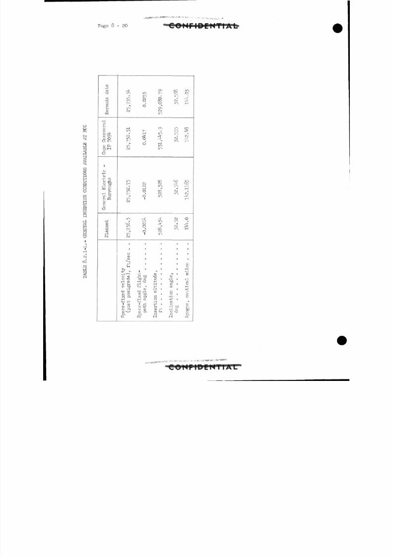
8/7/2019 Post Launch Memorandum Report for Mercury-Atlas No. 9(MA-9). Part 1 Mission Analysis
http://slidepdf.com/reader/full/post-launch-memorandum-report-for-mercury-atlas-no-9ma-9-part-1-mission 287/344
- 20
.•„*"•#-»'.• ' • ' • - • * • - i.
COMriDEMTIAL
o
gEH<
I
IHEH
OO
BO
@C QS
J
|
iiHlH
OJ
CO
Ha
C O•p
C O
C O•ti
pj0)
m
HCO
C D
1C O Oo t-
Q) PnftHC Oo
1
o•H
-p CO
CU bD
H O
H fncf l pfn mC DC
cuR
HP-i
KN.
L TA
P
LTNO J
H
d
t
ir\O J
K"At
OJ
f-
LT \CM
VDKNt
cu
ocuCO
^PrCjH
£>J
-p "
•H' *0 (UO 'dH CO
CD ^H|> bD
•HCD OX ft•HC j _ j _^3
1 COC D Oo ftCO -ftra
K^liAai
1
o
o
tH
0
d
OJOJH0
d
T Ho0
9
•
•.•i
-p^3 bDM cu•H jr-\Cj_j ^
cu•d Hcu wX P>
•H COIHi _<"]
CD -PO CO
ft^CO
ONt-
0
8•\
ONOJ[f\
ON,
LT \
t•s
H
L TN
COOJ
•N
COOJLT \
^j-
-\
COC\ j(C\
•
•
.
>
•\
cu •r Jj3 •
4J•H •-P
H •C O
HO ••H-P •in<U -pCO <H
aH
COV CITN
OJ
10LT \LTN
O JKN
voIrS
1
OJK~N,
OJITS•
OJN~\
-
•
.
•
»\ <
CDH •
bDG •C O
HO ••H•P •Bn•H MH CDo -d
H
fAO
jH-
3H
OJ
H
ir\HM
OJ_^J-
rH
O
_^-jj-
H
•
CO
CD
H•HB
HC OO•H
-PPC Os•\
CDcuboOft
, , v», ... ^ i- •• :*
> N I I fc* U I
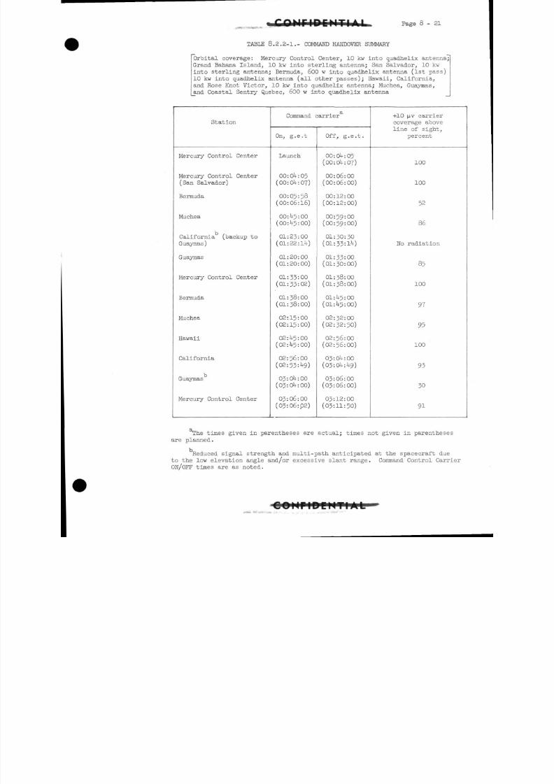
8/7/2019 Post Launch Memorandum Report for Mercury-Atlas No. 9(MA-9). Part 1 Mission Analysis
http://slidepdf.com/reader/full/post-launch-memorandum-report-for-mercury-atlas-no-9ma-9-part-1-mission 288/344
Page 8-21
TABLE 8.2.2-1.- COMMAND HANDOVER SUMMARY
Orbital coverage: Mercury Control Center, 10 kw into quadhelix antenna;
Grand Bahama Island, 10 kw into sterling antenna; San Salvador, 10 kw
into sterling antenna; Bermuda, 600 w into quadhelix antenna (1st pass)
10 kw into quadhelix antenna (all other passes); Hawaii, California,
and Rose Knot Victor, 10 kw into quadhelix antenna; Muchea, Guaymas,
and Coastal Sentry Quebec, 600 w into quadhelix antenna
Station
Mercury Control Center
Mercury Control Center
(San Salvador)
Bermuda
Muchea
California (backup to
Guaymas)
Guaymas
Mercury Control Center
Bermuda
Muchea
Hawaii
California
Guaymas
Mercury Control Center
Command carrier
On, g.e.t
Launch
00:04:05
(00:04:07)
00:05:58
(00:06:16)
00:45:00
(00:45:00)
01:23:00
(01:22:14)
01:20:00
(01:20:00)
01:33:00
(01:33:02)
01:38:00
(01:38:00)
02:15:00
(02:15:00)
02:45:00
(02:45:00)
02:56:00
(02:53:49)
03:04:00
(03:04:00)
03:06:00
(03:06:02)
Off, g.e.t.
00:04:05
(00:04:07)
00:06:00
(00:06:00)
00:12:00
(00:12:00)
00:59:00
(00:59:00)
01:30:30
(01:33:1 )
01:33:00
(01:30:00)
01:38:00
(01:38:00)
01:45:00
(01:45:00)
02: 32 : 00
(02:32:50)
02:56:00
(02:56:00)
03:04:00
(03:04:49)
03:06:00(03:06:00)
03:12:00
(03:11:50)
+10 [iv carrier
coverage above
line of sight,
percent
100
100
52
86
Mo radiation
85
100
97
95
100
93
30
91
xhe times given in parentheses are actual; times not given in parentheses
are planned.
Reduced signal strength and multi-path anticipated at the spacecraft due
to the low elevation angle and/or excessive slant range. Command Control Carrier
ON/OFF times are as noted.
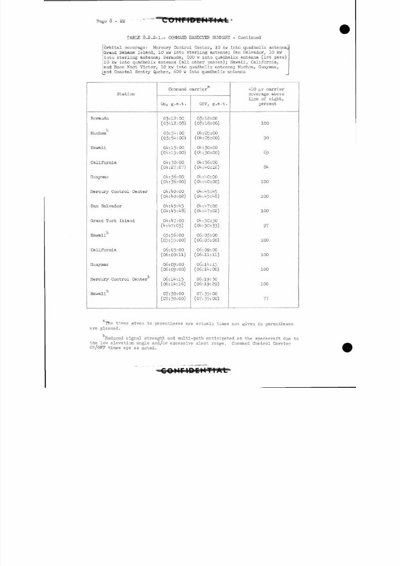
8/7/2019 Post Launch Memorandum Report for Mercury-Atlas No. 9(MA-9). Part 1 Mission Analysis
http://slidepdf.com/reader/full/post-launch-memorandum-report-for-mercury-atlas-no-9ma-9-part-1-mission 289/344
- 22
TABtE 8.2.2-1.- COMMAND HANDOVER SUMMARY - Continued
Orbital coverage: Mercury Control Center, 10 kw into quadhelix antenna
Grand Bahama Island, 10 kw into sterling antenna; San Salvador, 10 kwinto sterling antenna; Bermuda, 600 w into quadhelix antenna (1st pass)
10 kw into quadhelix antenna (all other passes); Hawaii, California,
and Rose Knot Victor, 10 kw into quadhelix antenna; Muchea, Guaymas,
and Coastal Sentry Quebec, 600 w into quadhelix antenna
Station
Bermuda
tMuchea
Hawaii
California
Guaymas
Mercury Control Center
San Salvador
Grand Turk Island
Hawaii
California
Guaymas
Mercury Control Center
Hawaii
13
Command carrier
On, g.e.t.
03:12:00
(03:12:03)
03:54:00
(03:54:00)
04:15:00(04:15:00)
04:30:00
(04:27:27)
04:36:00
(04:36:00)
04:40:00
(04:40:02)
04:45:45
( O k - . h - y - . k 8 )
o4:47:oo(4:47:03)
05=56:00
(05:55=00)
06:03:00
(06:00:11)
06:09:00
(06:09:00)
06:14:15
(06:14:16)
07:30:00(07:30:00)
Off, g.e.t.
03:18:00
(03:18:00)
04:05:00
(Ok: 05:00)
04:30:00(04:30:00)
Ok : 36: 00(04:40:12)
04:40:00
(04:40:00)
04:45:45
(04:45:48)
04:47:00(04:47:02)
04:50:30(04:50:33)
06:03:00
(06:03:00)
06:09:00
(06:11:11)
06:14:15
(06:14:00)
06:19:30
(06:19:29)
07:35:00(07:35:00)
+10 p,v carrier
coverage atove
line of sight,
percent
100
90
69
84
100
100
100
97
100
100
100
100
77
The times given in parentheses are actual; times not given in parenthesesare planned.
Reduced signal strength and multi-path anticipated at the spacecraft due to
the low elevation angle and/or excessive slant range. Command Control CarrierOH/OFF times are as noted.
c o u n s e l
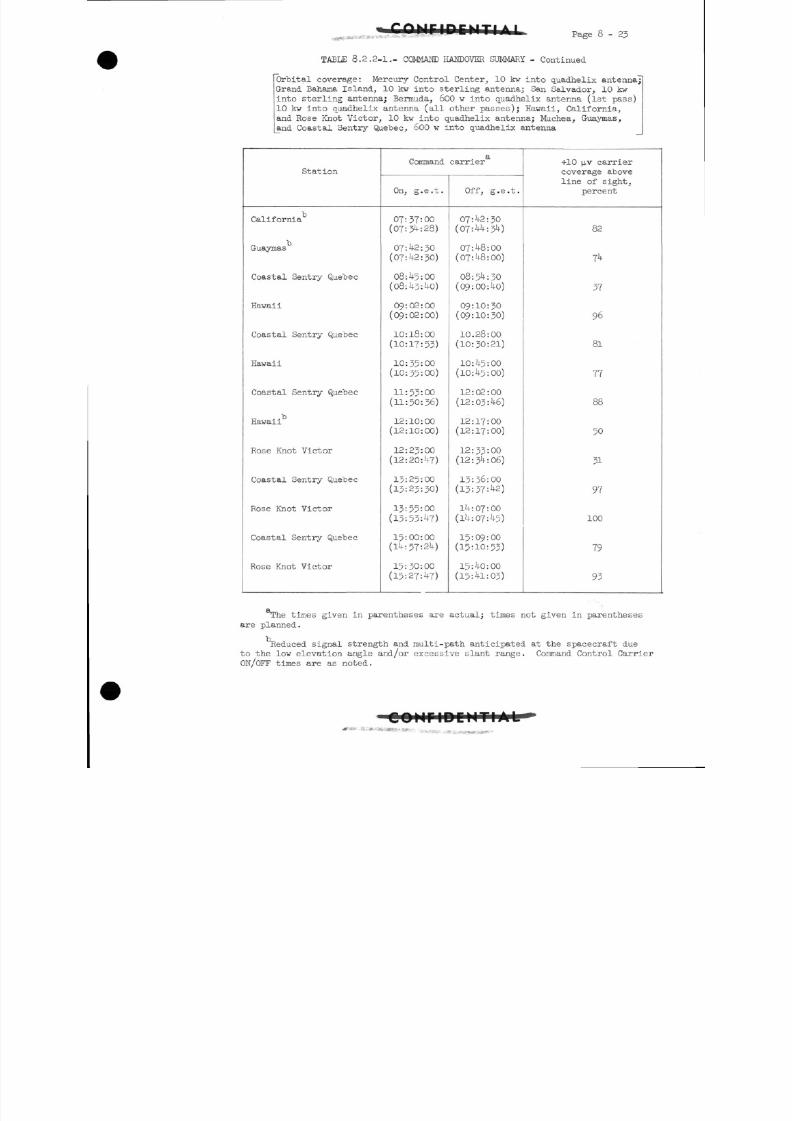
8/7/2019 Post Launch Memorandum Report for Mercury-Atlas No. 9(MA-9). Part 1 Mission Analysis
http://slidepdf.com/reader/full/post-launch-memorandum-report-for-mercury-atlas-no-9ma-9-part-1-mission 290/344
Page 8-23
TABLE 8.2.2-1.- COMMAND HANDOVER SUMMARY - Continued
Orbital coverage: Mercury Control Center, 10 kw into quadhelix antenna;
Grand Bahama Island, 10 kw into sterling antenna; San Salvador, 10 kw
into sterling antenna; Bermuda, 600 w into quadhelix antenna (1st pass)
10 kw into quadhelix antenna (all other passes); Hawaii, California,
and Rose Knot Victor, 10 kw into quadhelix antenna; Muchea, Guaymas,
and Coastal Sentry Quebec, 600 w into quadhelix antenna
Station
California13
Guaymas
Coastal Sentry Quebec
Hawaii
Coastal Sentry Quebec
Hawaii
Coastal Sentry Quebec
Hawaii13
Rose Knot Victor
Coastal Sentry Quebec
Rose Knot Victor
Coastal Sentry Quebec
Rose Knot Victor
Command carrier
On, g.e.t.
07:37:00
(07:34:28)
07:42:30
(07:42:30)
08:45:00(08:43:40)
09:02:00
(09:02:00)
10:18:00
(10:17:53)
10:35:00
(10:35:00)
11:53:00
(11:50:36)
12:10:00
(12:10:00)
12:23:00
(12:20:47)
13:25:00
(13:23:30)
13:55:00
(13:53:47)
15:00:00
(14:57:24)
15:30:00
(15:27:47)
Off, g.e.t.
07:42:30(07:44:34)
07:48:00(07:48:00)
08:54:30
(09:00:40)
09:10:30
(09:10:30)
10.28:00
(10:30:21)
10:45:00
(10:45:00)
12:02:00
(12:03:46)
12:17:00
(12:17:00)
12:33:00
(12:34:06)
13:36:00(13:37:42)
14:07:00
(14:07:45)
15:09:00
(15:10:53)
15:40:00
(15:41:03)
+10 p,v carrier
coverage above
line of sight,
percent
82
74
37
96
81
77
88
50
31
97
100
79
93
T?he times given in parentheses are actual; times not given in parentheses
are planned.
Reduced signal strength and multi-path anticipated at the spacecraft due
to the low elevation angle and/or excessive slant range. Command Control Carrier
ON/OFF times are as noted.
*
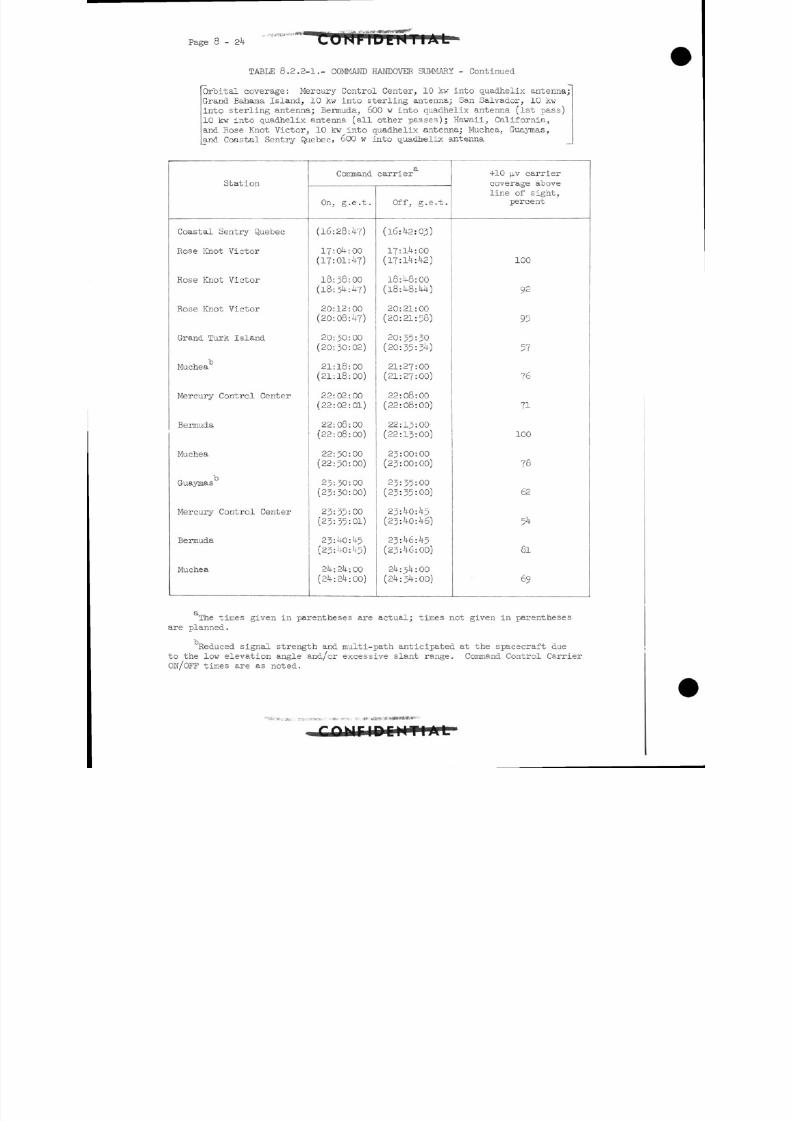
8/7/2019 Post Launch Memorandum Report for Mercury-Atlas No. 9(MA-9). Part 1 Mission Analysis
http://slidepdf.com/reader/full/post-launch-memorandum-report-for-mercury-atlas-no-9ma-9-part-1-mission 291/344
Page 8-24
TABLE 8.2.2-1.- COMMAND HANDOVER SUMMARY - Continued
Orbital coverage: Mercury Control Center, 10 kw into quadhelix antenna;
Grand Bahama Island, 10 kw into sterling antenna; San Salvador, 10 kw
into sterling antenna; Bermuda, 600 w into quadhelix antenna (1st pass)
10 kw into quadhelix antenna (all other passes); Hawaii, California,
and Rose Knot Victor, 10 kw into quadhelix antenna; Muchea, Guaymas,
and Coastal Sentry Quebec, 600 w into quadhelix antenna
Station
Coastal Sentry Quebec
Rose Knot Victor
Rose Knot Victor
Rose Knot Victor
Grand Turk Island
Muchea
Mercury Control Center
Bermuda
Muchea
Guaymas
Mercury Control Center
Bermuda
Muchea
Command carrier
On, g.e.t.
(16:28:47)
17:04:00
(17:01:4?)
18:38:00
(18:34:47)
20:12:00
(20:08:47)
20:30:00
(20:30:02)
21:18:00
(21:18:00)
22:02:00
(22:02:01)
22:08:00
(22:08:00)
22:50:00
(22:50:00)
23:30:00
(23:30:00)
23:35:00
(23:35:01)
23:40:45
(23:40:45)
24:24:00(24:24:00)
Off, g.e.t.
(l6:42:0j)
17:14:00(17:14:42)
18:48:00
(18:48:44)
20:21:00
(20:21:58)
20:35:30
(20:35:34)
21:27:00
(21:27:00)
22:08:00
(22:08:00)
22:13:00
(22:13:00)
23:00:00
(23:00:00)
23:35:00
(23:35:00)
23:40:45
(23:40:46)
23:46:45
(23:46:00)
24:34:00
(24:34:00)
+10 | _ L V carrier
coverage above
line of sight,
percent
100
92
95
57
76
71
100
78
62
54
81
69
The times given in parentheses are actual; times not given in parentheses
are planned.
Reduced signal strength and multi-path anticipated at the spacecraft due
to the low elevation angle and/or excessive slant range. Command Control Carrier
ON/OFF times are as noted.
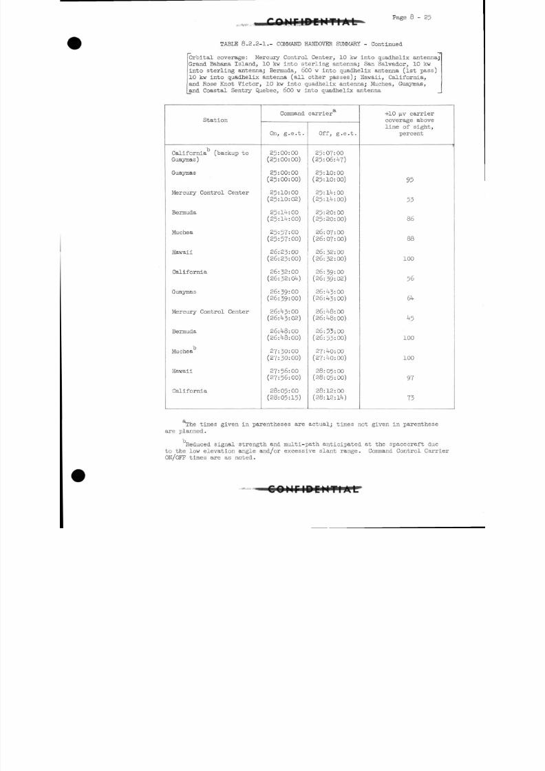
8/7/2019 Post Launch Memorandum Report for Mercury-Atlas No. 9(MA-9). Part 1 Mission Analysis
http://slidepdf.com/reader/full/post-launch-memorandum-report-for-mercury-atlas-no-9ma-9-part-1-mission 292/344
Page 8-25
TABLE 8.2.2-1.- COMMAND HANDOVER SUMMARY - Continued
Orbital coverage: Mercury Control Center, 10 kw into quadhelix antenna;
Grand Bahama Island, 10 kw into sterling antenna; San Salvador, 10 kw
into sterling antenna; Bermuda, 600 w into quadhelix antenna (1st pass)
10 kw into quadhelix antenna (all other passes); Hawaii, California,
and Rose Knot Victor, 10 kw into quadhelix antenna; Muchea, Guaymas,
_and Coastal Sentry Quebec, 600 w into quadhelix antenna
Station
California (backup to
Guaymas)
Guaymas
Mercury Control Center
Bermuda
Muchea
Hawaii
California
Guaymas
Mercury Control Center
Bermuda
Muchea
Hawaii
California
Command carrier
On, g.e.t.
25:00:00
(25:00:00)
25:00:00
(25:00:00)
25:10:00
(25:10:02)
25:14:00
(25:14:00)
25:57:00
(25:57:00)
26:23:00
(26:23:00)
26:32:00
(26:32:04)
26:39:00
(26:39=00)
26:43:00
(26:43:02)
26:48:00
(26:48:00)
27:30:00
(27:30:00)
27:56:00
(27:56:00)
28:05:00
(28:05:15)
Off, g.e.t.
25:07:00
(25:06:47)
25:10:00
(25:10:00)
25:14:00
(25:14:00)
25:20:00
(25:20:00)
26:07:00
(26:07:00)
26:32:00
(26:32:00)
26:39:00
(26:39:02)
26:43:00
(26:43:00)
26:48:00
(26:48:00)
26:53:00
(26:53:00)
27:40:00
(27:40:00)
28:05:00
(28:05:00)
28:12:00
(28:12:14)
+10 n,v carrier
coverage above
line of sight,
percent
1
95
55
86
88
100
56
64
5
100
100
97
73
T?he times given in parentheses are actual; times not given in parenthese
are planned.
Reduced signal strength and multi-path anticipated at the spacecraft due
to the low elevation angle and/or excessive slant range. Command Control Carrier
OH/OFF times are as noted.
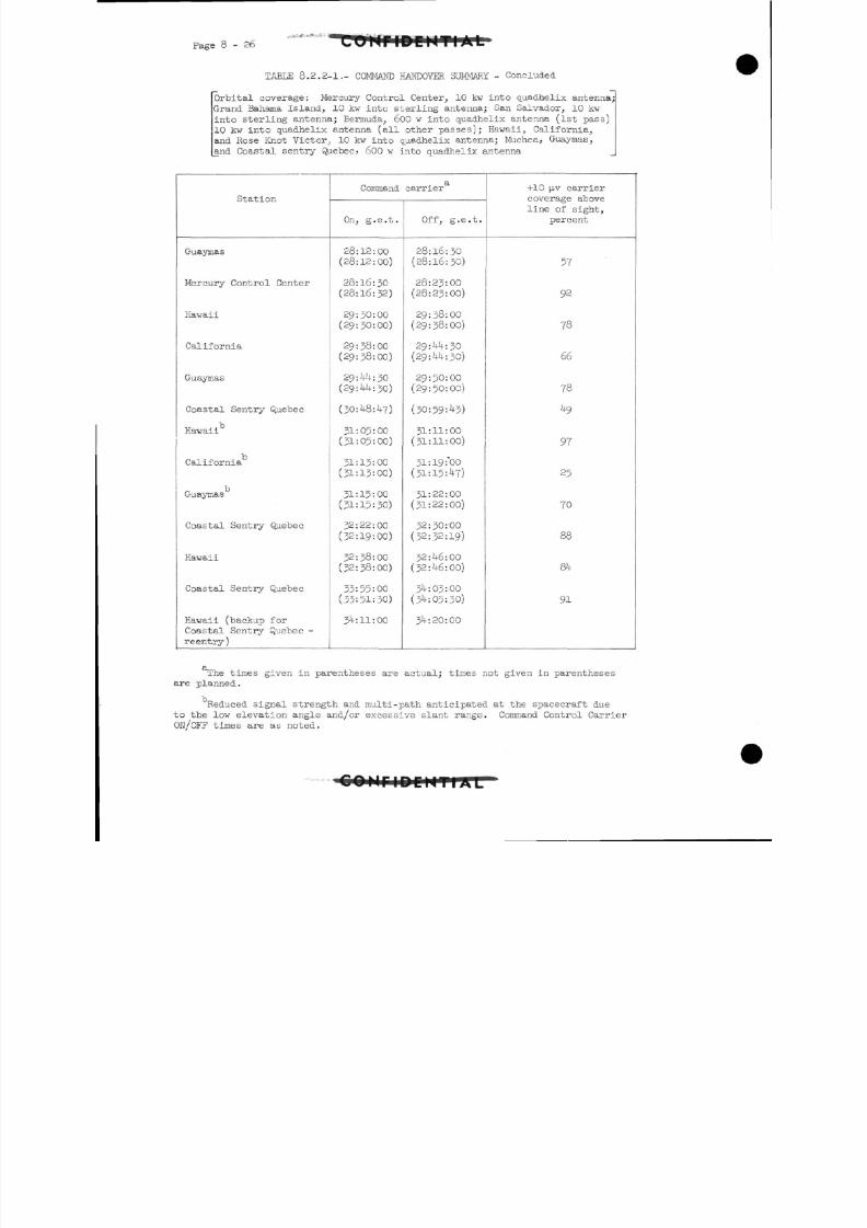
8/7/2019 Post Launch Memorandum Report for Mercury-Atlas No. 9(MA-9). Part 1 Mission Analysis
http://slidepdf.com/reader/full/post-launch-memorandum-report-for-mercury-atlas-no-9ma-9-part-1-mission 293/344
Page 8-26
TABI£ 8.2.2-1.- COMMAND HANDOVER SUMMARY - Concluded
Orbital coverage: Mercury Control Center, 10 kw into quadhelix antenna;
Grand Bahama Island, 10 kw into sterling antenna; San Salvador, 10 kw
into sterling antenna; Bermuda, 600 w into quadhelix antenna (1st pass)
10 kw into quadhelix antenna (all other passes); Hawaii, California,
and Rose Knot Victor, 10 kw into quadhelix antenna; Muchea, Guaymas,
and Coastal sentry Quebec* 600 w into quadhelix antenna
Station
Guaymas
Mercury Control Center
Hawaii
California
Guaymas
Coastal Sentry Quebec
. .bHawaii
California
Guaymas
Coastal Sentry Quebec
Hawaii
Coastal Sentry Quebec
Hawaii (backup for
Coastal Sentry Quebec -
reentry)
Command carrier
On, g.e.t.
28:12:00
(28:12:00)
28:16:30
(28:16:32)
29:30:00
(29:30:00)
29:38:00
(29:38:00)
29:1)4:30
(29:1(4:30)
(30:48:47)
31:05:00
(31:05:00)
31:13:00
(31:13:00)
31:15:00
(31:15:30)
32:22:00
(32:19:00)
32:38:00
(32:38:00)
35:55:00
(33:51:30)
34:11:00
Off, g.e.t.
28:16:30
(28:16:30)
28:23:00
(28:23:00)
29:38:00
(29:38:00)
29:44:30
(29:44:30)
29:50:00
(29:50:00)
(30:59: 3)
31 : 11 : 00(31:11:00)
31: 19 :~00
(31: 1 5 - A T )
31:22:00
(31:22:00)
32:30:'00
(32:32:19)
32:46:00
(32:46:00)
34:03:00
(34:05:30)
34:20:00
+10 u.v carrier
coverage above
line of sight,
percent
57
92
78
66
78
49
97
25
70
88
84
91
times given in parentheses are actual; times not given in parentheses
are planned.
Reduced signal strength and multi-path anticipated at the spacecraft due
to the low elevation angle and/or excessive slant range. Command Control Carrier
ON/OFF times are as noted.
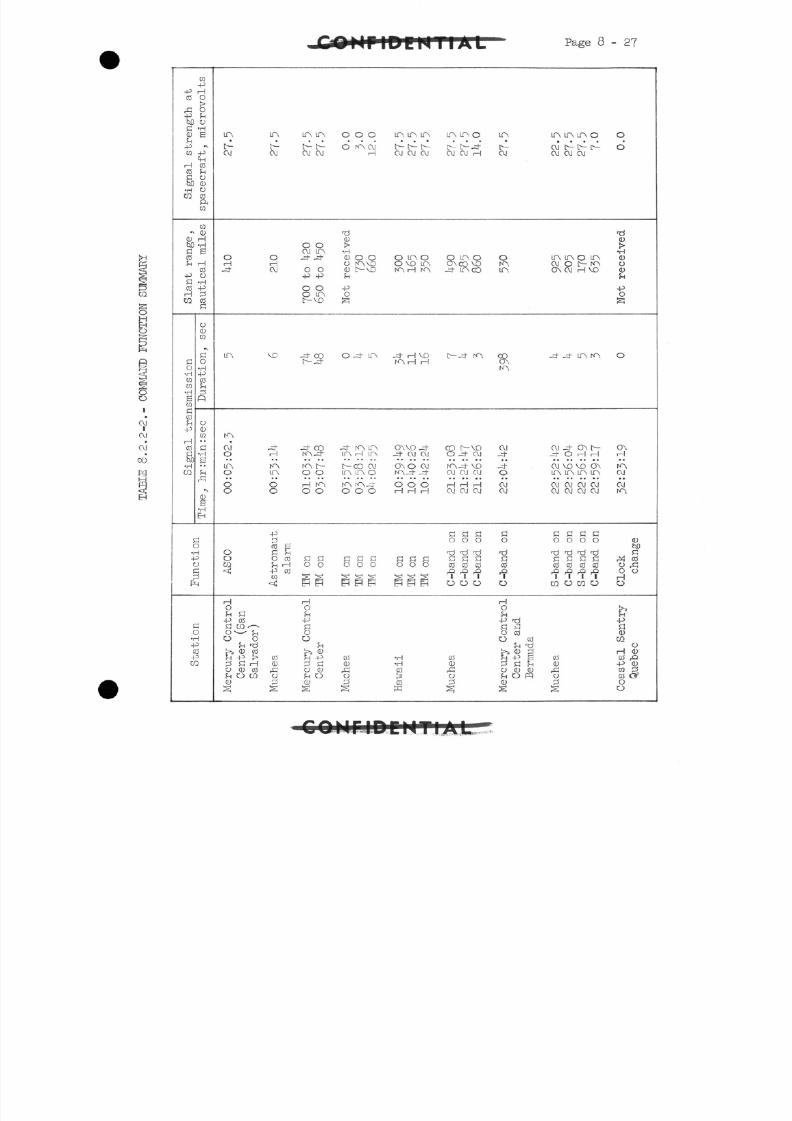
8/7/2019 Post Launch Memorandum Report for Mercury-Atlas No. 9(MA-9). Part 1 Mission Analysis
http://slidepdf.com/reader/full/post-launch-memorandum-report-for-mercury-atlas-no-9ma-9-part-1-mission 294/344
Page 8-27
gH
O
I
O J
C M•
C X I
CO
C Q-p
-P HC O O
& 0-P rH
bD ofi -H
0) Be .rH
CO -P
H COC O fn
S) CL)•H 0w
&CO
C O*• CD
C O HM -Hfi BC OrH H
CO
-P 0S -H
C O -PH 302 CO
O
C Q
•N
aG o0 -H•H -P
C Q C O
CQ rH
13CQ
flC OrH 0
-P CD
CQi 1 " •
C O f l
ffl'gQ JJ p:•H ••CQ rH
"
•X
a >
•HE H
SO•H-POr_j
H
fi
C
0•H-P
C O-pCQ
U A LT\ LtA UA OOO LfA UA UA
b- [>- t^ C O HA OJ IT l>- tC M O J C X J C M H C M C M C M
TdC O
o o >CXI UA -rl
O O -3--3- C D O O QLP\OH rH O I<AVO O VO LT\-4" CM O O 0) t VO KA H fA
I,1 1 1 t.
O O -PO LTA OI VD ^
L P \ VO -COO-^"LO\ -^HVOt -3F KA H rH
KA
O J J- _^- CO -4- KA IT\ OAVD _4-O H NA-^F LT\ rH LTN -^- CXI CM
L T \ KA NA f- tCOOJ OAOCMO \T\ O O LT\ UA O KA_4- -3"
O O rH K> KAr<A-4" OOOO O OO OOO rHHrH
-P
C O SO d H
O O c o f l r ! SSC C S f lO 2 r i H O O OOO<t j -P CO
< EH0 PPB PPEH
rH rH
0 0
rH G rH
-P CO -P
fi02^ aO *• ^ f-i OO 0 O
rH li rH
>2 0) CO >5 CUr H - P f > C O SH-P CO -Hp l f iHO) ^S CL> -HOCUCOr Cl CJ CD r C! CO
r H O C Q O fnO O >CU ^ CU ^ COS S S S K
ir\ U A o
C M CXJ H
O Lf\ O
-3~ LfA CO
t-tK>
C O t-VOO J-CM
MA-H/ VOCM OJ CM
H H HC X I C X I C M
fl S flO O O
r£j rj rjj
s a aC O C O C Oo o o1 1 1
OOO
C O<L >
O
^3s
L \
cV
0
UA
COO AK~\
O J
j-0
O JO J
j-H
o
ndaroo1
O
H0rH-P Tjfn H
O COO CO
rH Tj
h v 3M-P S
3 S SO CD brH C ffl
C Dg
L( A LtA LtA O
CXI t^- C^- t^-CM CXI CM
UA LT\ O LtACM O C^ KAO\ CMH VO
_HT J- UA NA
OJ J- ON D
CXI VO VD OALtA UA UA L!A
O J C M C M C MC X J CXJ CXI OJ
a a a a0 0 O O
T S Ti 'tj tjfi fi fi SC O C O C O C Oo o o o1 1 1 1
02 0CQ 0
C O<DA
pf
S
0
d
0)>•H
CDOCDrH
-P
O
*
o
O AH
HAC X J
C X IHA
0)
rjj
r*! COC -> rGo oH
O
r?
-P
fl
(U02
CJ
H CD
-P CUC Q rsC O C 3?oo
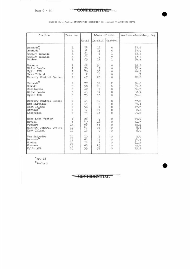
8/7/2019 Post Launch Memorandum Report for Mercury-Atlas No. 9(MA-9). Part 1 Mission Analysis
http://slidepdf.com/reader/full/post-launch-memorandum-report-for-mercury-atlas-no-9ma-9-part-1-mission 295/344
Page 8 - 2 8 • C O N F I D E N T I A L
TABLE 8.2.3-1.- COMPUTER READOUT OF RADAR TRACKING DATA
Station
1a
Bermuda,
Bermuda
Canary Islands
Canary IslandsMuchea
Woomera
White Sands
Eglin AFB
East Island
Mercury Control Center
Bermuda
Hawaii
California
White Sands
Eglin AFB
Mercury Control Center
San SalvadorEast Island
Bermuda
Ascension
Rose Knot Victor
Hawaii
Woomera
Mercury Control Center
East Island
San Salvador
BermudaMuchea
Woomera
Eglin AFB
Pass no.
1
11
1
1
1112
2
2
3
333
1 *
k444
77141515
15
15151515
Total
7^7k6162
85
62
36702
67
775042
573
45
15564773
26
49584715
10
647466
59
Lines of data
Invalid
18
173311
38
9332
25
5228
71410
32
01
4T13
01833250
3
172
29
37
Garbled
0
01
01
000
00
2
40
0
0
0
00
0
0
0
00
0
0
0
000
0
Maximum elevation, deg
67-567-572.172.164.4
7 9 - 215.444.9
.718.2
96.025.036.580.936.6
37-2
84.447.72.825.0
59-0
71.770.2
8.86.9
2.0
14. 361.2
49.425.2
FPS-16
Verlort
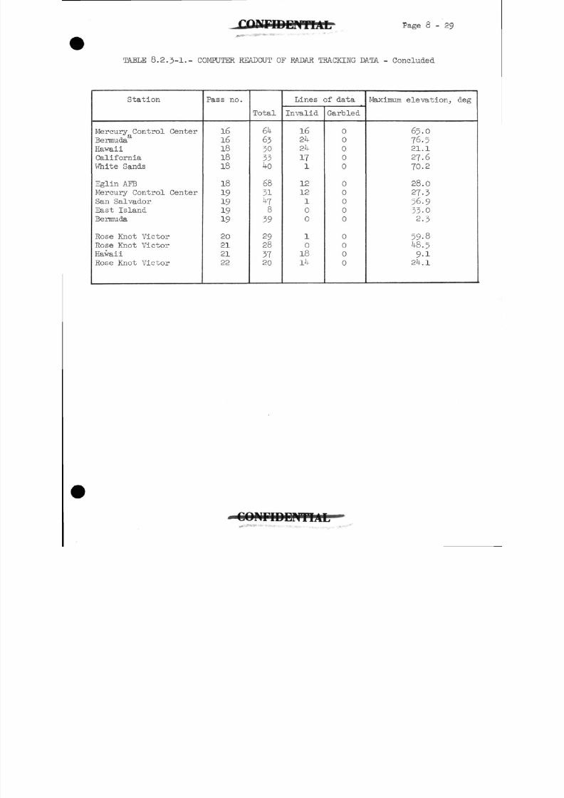
8/7/2019 Post Launch Memorandum Report for Mercury-Atlas No. 9(MA-9). Part 1 Mission Analysis
http://slidepdf.com/reader/full/post-launch-memorandum-report-for-mercury-atlas-no-9ma-9-part-1-mission 296/344
Page 8 - 2 9
TABLE 8.2.3-1.- COMPUTER READOUT OF RADAR TRACKING DATA - Concluded
Station
Mercury Control CenterBermuda
HawaiiCaliforniaWhite Sands
Eglin AFBMercury Control CenterSan Salvador
East IslandBermuda
Rose Knot Victor
Rose Knot VictorHawaiiRose Knot Victor
Pas s no .
16
16
181818
18
19191919
20
21
21
22
Total
€ k6 3303 31 * 0
6831kl
839
2928
3720
Lines of data
Invalid
1624
2k
171
12
12
1
00
1
01814
Garbled
00
0
0
0
0
0
0
00
0
0
0
0
Maximum elevation, deg
65.0
76.521.1
27.6
70.2
28.0
27-3
56.9
3 3 - 02 - 3
59-848.59 - 1
24.1
C O N F I D E N T I A L..»_
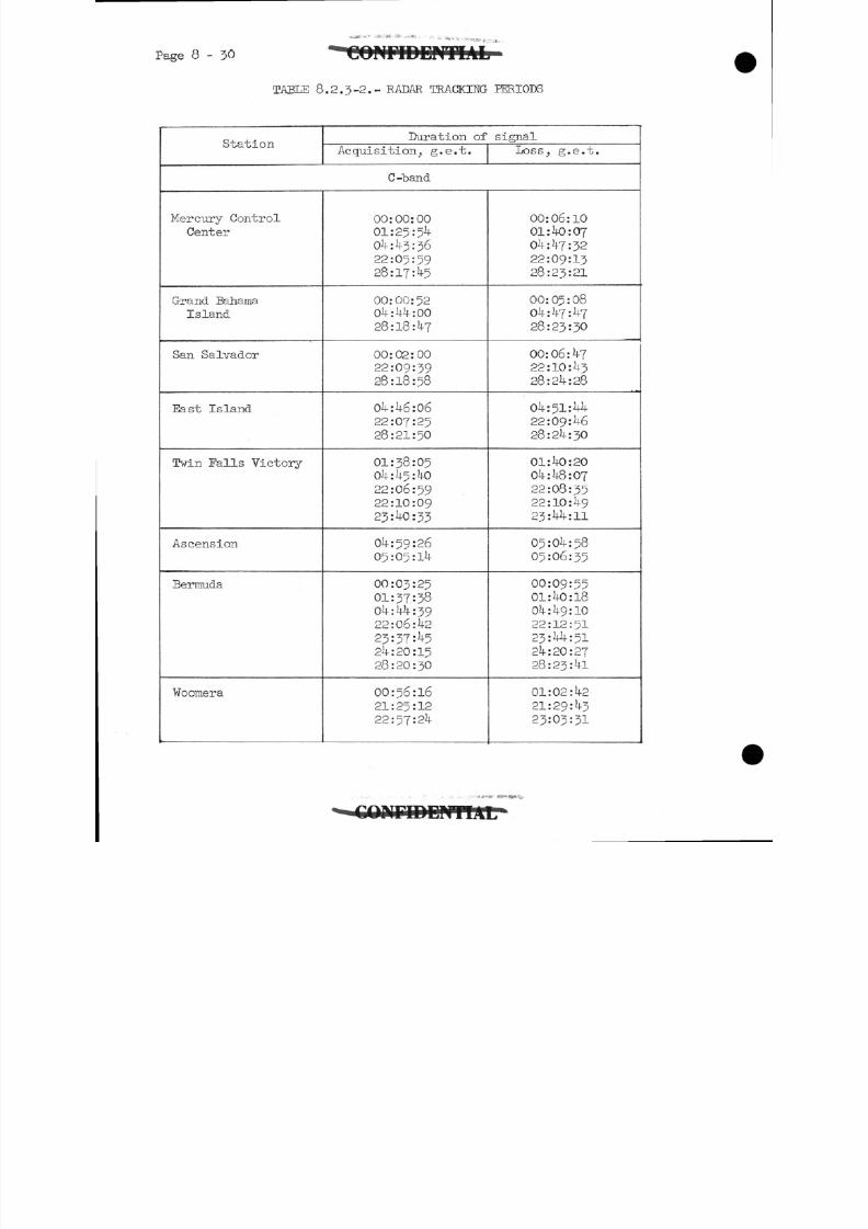
8/7/2019 Post Launch Memorandum Report for Mercury-Atlas No. 9(MA-9). Part 1 Mission Analysis
http://slidepdf.com/reader/full/post-launch-memorandum-report-for-mercury-atlas-no-9ma-9-part-1-mission 297/344
8 - 30
T A B L E 8.2.3-2.- R A D A R T R A C K I N G P E R I O D S
StationDuration of signal
Acquisition, g.e.t. Loss, g.e.t.
C-"band
Mercury Control
Center
Grand Bahama
Island
San Salvador
East Island
Twin Falls Victory
Ascension
Bermuda
Woomera
00:00:0001:25:5404:43:36
22:05:59
28:17:45
00:00:52O i l - : 114:0028:18:47
00:02:0022:09:39
28:18:58
04:U6:0622:07:25
28:21:50
01:38:05
05:0
22:06:59
22:10:09
23: 0:33
Olf:59:2605:05:lU
00:03:25
01:37:38Ol4-:l| :39
22:06: 2
23:37: 52 :20:15
28:20:30
00:56:16
21:25:12
22:57:2
00:06:1001:itO:07
Oi4-:^7:32
22:09:13
28:23:21
00:05:0804:Vf:V7
28:23:30
00:06: 7
22:10:1+328:24:28
04:51:22:09:46
28:24:30
01:40:2004:48:07
22:08:3522:10:49
23:44:11
05:04:58
05:06:35
00:09:55
01:40:18
04:49:10
22:12:51
23:44:5124:20:27
28:23:41
01:02:4221:29:43
23:03=31
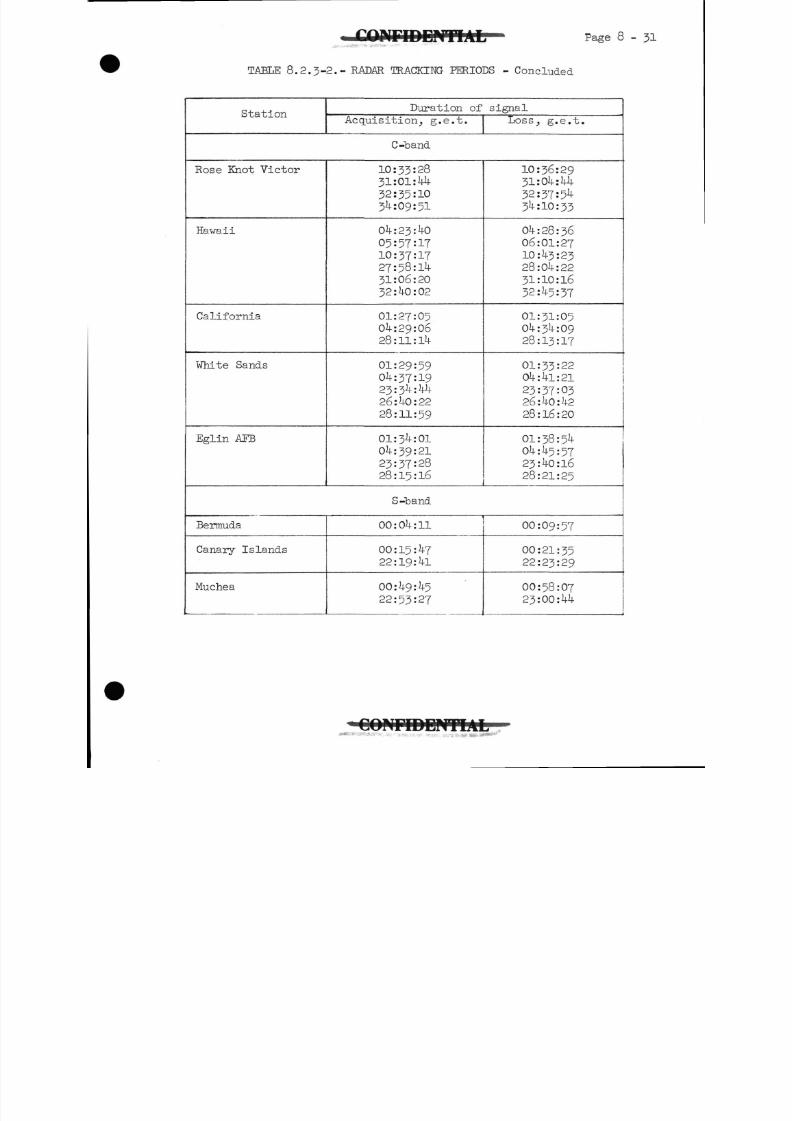
8/7/2019 Post Launch Memorandum Report for Mercury-Atlas No. 9(MA-9). Part 1 Mission Analysis
http://slidepdf.com/reader/full/post-launch-memorandum-report-for-mercury-atlas-no-9ma-9-part-1-mission 298/344
TABLE 8.2.3-2.- RADAR TRACKING PERIODS - Concluded
StationDuration of signal
Acquisition, g.e.t. Loss, g.e.t.
C-band
Rose Knot Victor
Hawaii
California
White Sands
Eglin APE
10:33:2831:01:44
32:35:1034:09:51
04:23:40
05:57=1710:37:1727:58:14
31:06:20
32:40:02
01:27:05
04:29:06
28:ll:lU
01:29:5904:37:19
23:34:1*426:40:22
28:11:59
01:34:0104:39:21
23:37:28
28:15:16
10:36:2931:04:44
32:37:5434:10:33
04:28:3606:01:2710:43:2328:04:2231:10:16
32:45:37
01:31:0504:34:0928:13:17
01:33:22
04:41:21
23:37:0326:40:42
28:16:20
01:38:5404:4-5:57
23:40:16
28:21:25
S-band
Bermuda
Canary Islands
Muchea
00:04:11
00:15:47
22:19:41
00:49:45
22:53:27
00:09:57
00:21:35
22:23:29
00:58:07
23:00:44
C O N F I D E N T I A L... •* - .
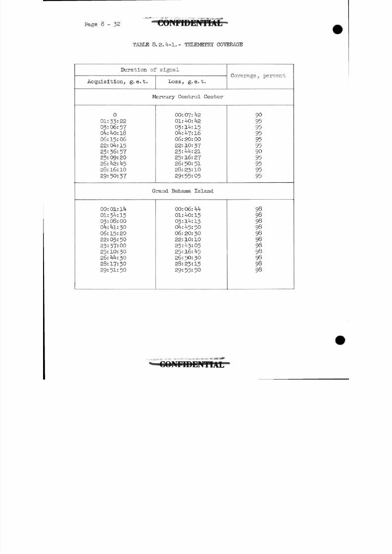
8/7/2019 Post Launch Memorandum Report for Mercury-Atlas No. 9(MA-9). Part 1 Mission Analysis
http://slidepdf.com/reader/full/post-launch-memorandum-report-for-mercury-atlas-no-9ma-9-part-1-mission 299/344
Page 8-32
TABLE 8.2.4-1.- TELEMETRY COVERAGE
Duration of signal
Acquisition, g. e.t. Loss, g. e. t.Coverage., percent
Mercury Control Center
0
01:33:2203:06:57
Ok: kO: 1806:15:06
22:04:15
23:36:5?25:09:20
26:42: 4528:16:10
29:50:37
00: 07: k201: 40: 42
03:14:15
Ok: 47: 1606:20:00
22:10:3723:44:21
25:16:2726:50:51
28:23:10
29:55:05
90
95959595
959095959595
Grand Bahama Island
00:01:14
01:34:1503:08:0004:41:30
06:15:20
22:03:50
23:37:00
25:10:30
26:44:30
28:17:30
29:51:50
00:06:44
01:40:1503:14:13
04:45:50
06:20:30
22:10:10
23:43:0525:16:45
26:50:3028:23:1529:55:50
98
98989898989898989898
* -ii "r ,
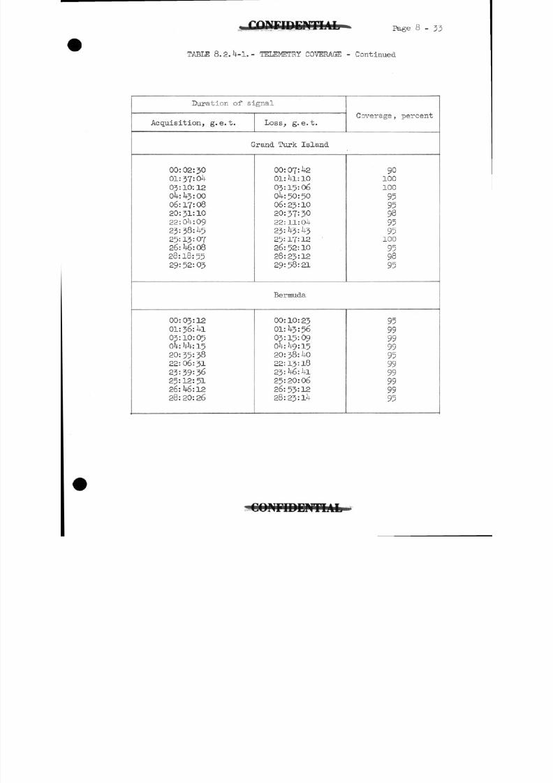
8/7/2019 Post Launch Memorandum Report for Mercury-Atlas No. 9(MA-9). Part 1 Mission Analysis
http://slidepdf.com/reader/full/post-launch-memorandum-report-for-mercury-atlas-no-9ma-9-part-1-mission 300/344
Page 8-33
TABLE 8.2.4-1.- TELEMETRY COVERAGE - Continued
Duration of signal
Acquisition, g. e.t. Loss, g. e.t.Coverage , percent
Grand Turk Island
00:02:30
01:37:0403:10:1204:43:00
06:17:0820:31:1022:04:09
23=38:45
25:13:0?26:46:08
28:18:5529:52=03
00: 07: 4201:41:10
03:15:0604:50:50
06:23:1020:37=3022:11:0423=43:4325:17:12
26:52:10
28:23:12
29: 58: 21
90100
100
95
95989595100
959895
Bermuda
00:03:12
01:36:4103:10:05
04: 44: 1520:35:38
22:06:31
23:39:36
25:12:5126:46:1228:20:26
00:10:2301:43:5603:15:0904:49:15
20:38:40
22:13:18
23:46:41
25:20:06
26:53=1228:23:14
95999999959999999995
O O M T D D M I A f c
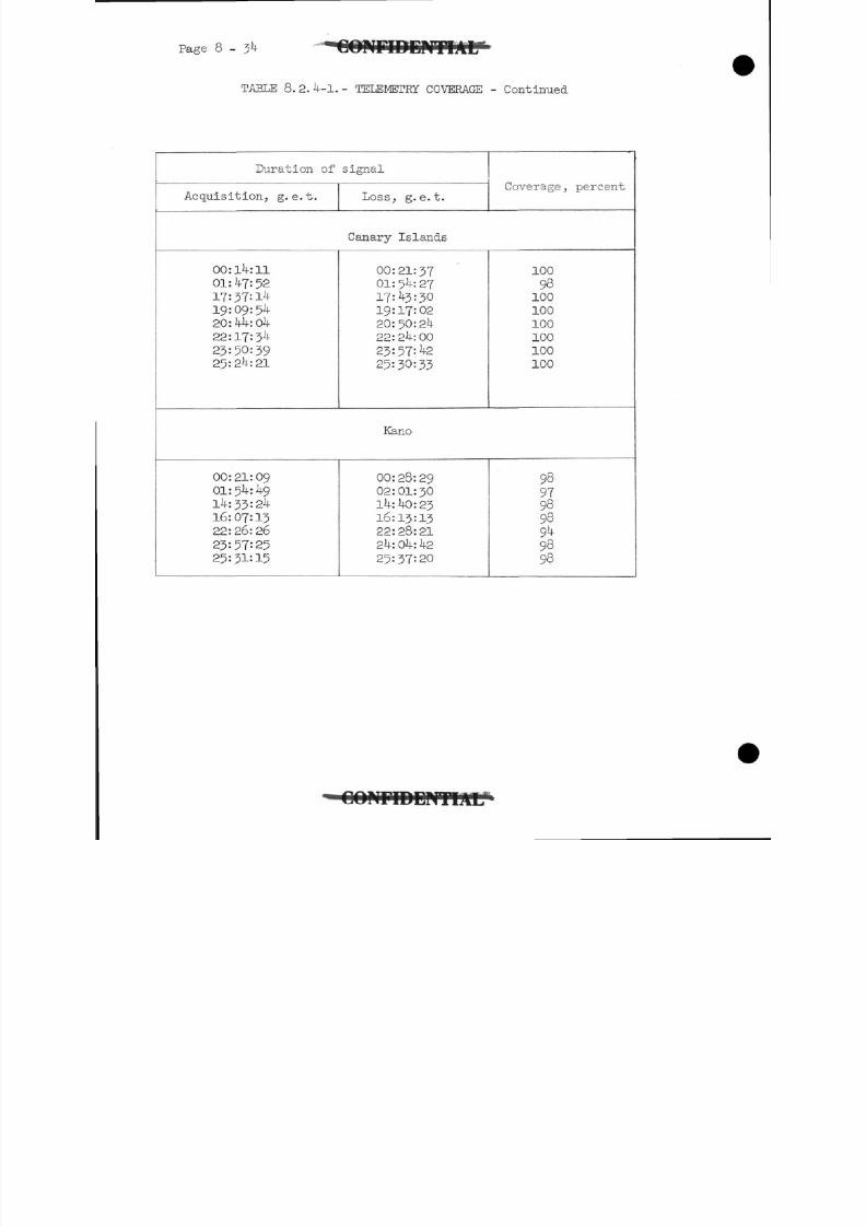
8/7/2019 Post Launch Memorandum Report for Mercury-Atlas No. 9(MA-9). Part 1 Mission Analysis
http://slidepdf.com/reader/full/post-launch-memorandum-report-for-mercury-atlas-no-9ma-9-part-1-mission 301/344
TABLE 8. 2. 4-1. - TELEMETRY COVERAGE - Continued
Duration of signal
Acquisition, g. e.t. Loss, g. e.t.Coverage ^ percent
Canary Islands
00:14:1101:47:5217=37:1419:09:5420:44:0422: 17:34
23:50:3925:24:21
00:21:37
01: 54: 2717:43 = 3019:17:02
20:50:24
22:24:00
23:57:42
25=30=33
100
98
100
100
100
100
100
100
Kano
00:21:0901:54:4914:33:24
16:07:13
22:26:26
23=57:25
25:31:15
00:28:2902:01:30
14:40:23
16:13:13
22:28:21
24: 04: 4225:37:20
98979898949898
OONnDDPiTIAL1
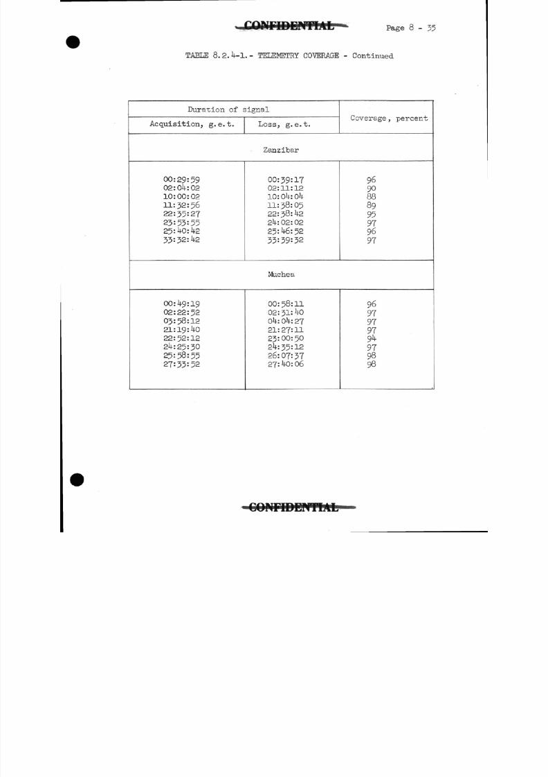
8/7/2019 Post Launch Memorandum Report for Mercury-Atlas No. 9(MA-9). Part 1 Mission Analysis
http://slidepdf.com/reader/full/post-launch-memorandum-report-for-mercury-atlas-no-9ma-9-part-1-mission 302/344
Page 8 - 35
TABLE 8. 2. 4-1. - TELEMETRY COVERAGE - Continued
Duration of signal
Acquisition, g. e.t. Loss, g. e.t.Coverage, percent
Zanzibar
00:29:5902:04:02
10:00:0211:52:5622:35:2?
23=53:5525:40:42
33: 32: 42
00:39:1702:11:1210: Ok: 0411:38:0522: 38: 4224:02:02
25:46:52
33=39:32
9690888995979697
Muchea
00:49:1902:22:52
03:58:1221:19:40
22:52:1224:25:30
25:58:5527:33:52
00:58:1102:31:40
04:04:2721:27:1123:00:50
24:35:1226:07=3727:40:06
9697979794979898
C O M r i D D W T I A L
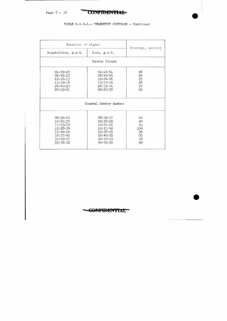
8/7/2019 Post Launch Memorandum Report for Mercury-Atlas No. 9(MA-9). Part 1 Mission Analysis
http://slidepdf.com/reader/full/post-launch-memorandum-report-for-mercury-atlas-no-9ma-9-part-1-mission 303/344
Page 8-36
TABLE 8.2.4-1.- TELEMETRY COVERAGE - Continued
Duration of signal
Acquisition, g. e.t. Loss, g. e.t.
Coverage } percent
Canton Island
01:09:2502:43:10
12:16:15
13:50:14
24:11-5:2526:19:21
01:l6:4l02:49:45
12:24:06
13:57:0324:53:01
26:25=35
989995
989799
Coastal Sentry Quebec
08:52:00
10:21:30
11:55:0?13:28:34
15:02:02
16:37:4532:23:26
33:56:52
08:54:5710:28:22
12:01:4613:35:4215:08:03
16: 40: 0332:30:19
34:03:30
4090
95100
95059890
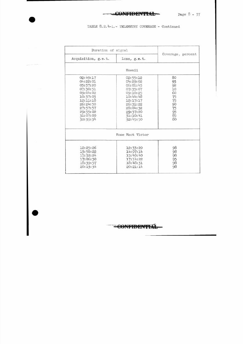
8/7/2019 Post Launch Memorandum Report for Mercury-Atlas No. 9(MA-9). Part 1 Mission Analysis
http://slidepdf.com/reader/full/post-launch-memorandum-report-for-mercury-atlas-no-9ma-9-part-1-mission 304/344
. C O i n T D D O T f A L Page 8-37
TABLE 8.2.4-1.-- TELEMETRY COVERAGE - Continued
Duration of signal
Acquisition, g. e.t. Loss, g. e.t.
Coverage .percent
Hawaii
02:49:1704:22:01
05:57:20
07:30:5109:04:0210: 37: 0312:11:1826:24:50
27:57:5729:35:0231:07:00
32:39:3
02:55:12
04:29:0206: 01: 45
07:35:0709:10:25
10:44:48
12:17:1726:31:22
28:04:3229:37:20
31:10:4132:45:50
809392
106075759075958580
Rose Knot Victor
12:25:26
13:58:22
15:32:2417:06:30
18:39:5720:13:34
12:33:20
14: 07: 14
15:40: 4017:14:2218:48:3120:21:14
989898939898
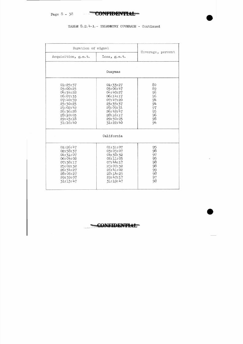
8/7/2019 Post Launch Memorandum Report for Mercury-Atlas No. 9(MA-9). Part 1 Mission Analysis
http://slidepdf.com/reader/full/post-launch-memorandum-report-for-mercury-atlas-no-9ma-9-part-1-mission 305/344
Page 8-38
TABLE 8.2.4-1.- TELEMETRY COVERAGE -Continued
Duration of signal
Acquisition, g. e.t. Loss, g.e.t.
Coverage, percent
Guaymas
01:25:57
03:00:2304:34:22
06:07:33
07:40:59
23:30:23
25:02:4226:36:2828:10:03
29:43:18
31: 16: hO
01:33:27
03:06:4704:40:2706:14:1707:47:20
23:35:3725:09:31
26:42: 4728:16:1729: 50: 0331:22:40
80
89969694949795969894
California
01:26:4?02:58:3704:31:0706:04:0207:38:17
25:02:3226:34:27
28:06:27
29:39:0731:13=47
01:31:07
03:05:07
04:38:32
06:11:0307:44:17
25:07:32
26:41:02
28:14:2529:47:17
31:19=47
95989795989899989798
C O I U r i D D N T I A t r
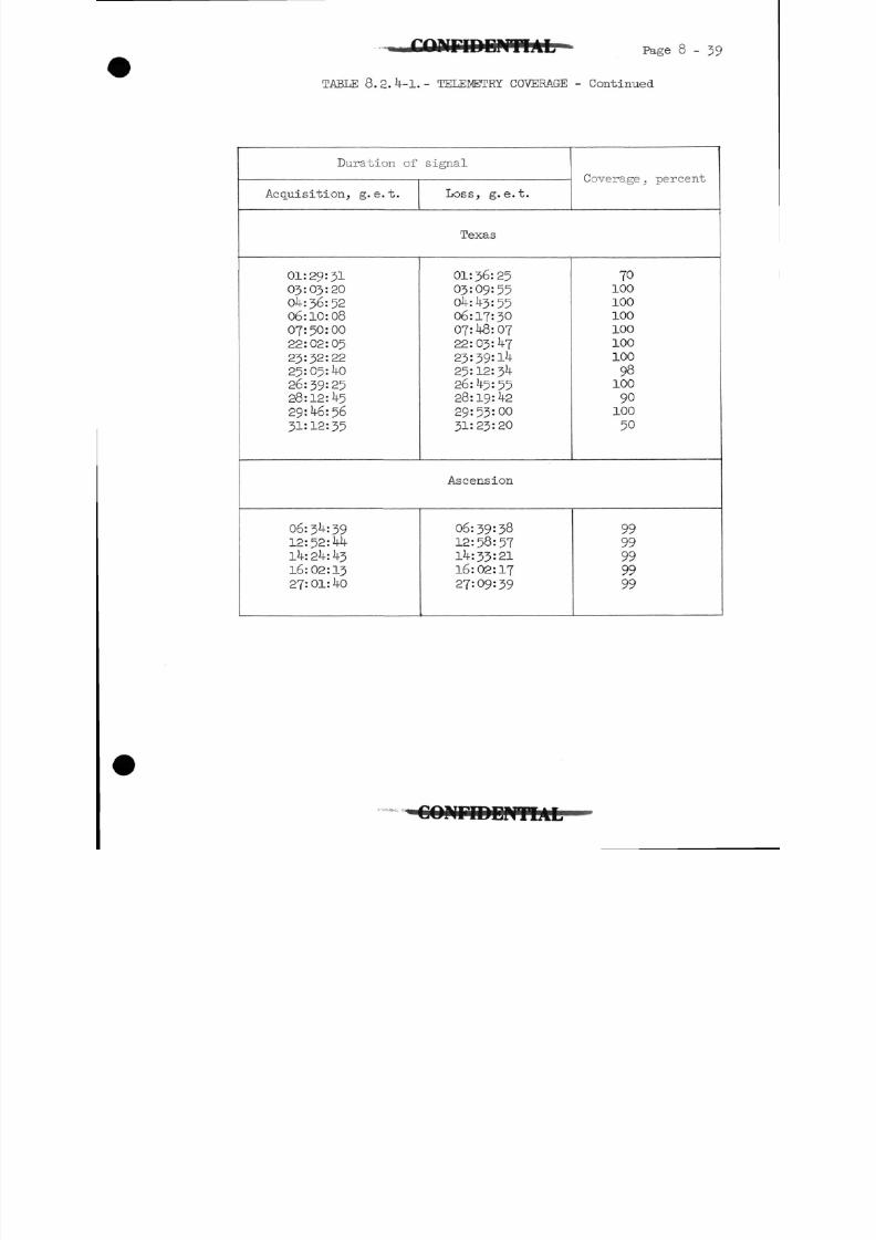
8/7/2019 Post Launch Memorandum Report for Mercury-Atlas No. 9(MA-9). Part 1 Mission Analysis
http://slidepdf.com/reader/full/post-launch-memorandum-report-for-mercury-atlas-no-9ma-9-part-1-mission 306/344
Page 8-39
TABLE 8.2. -1.- TELEMETRY COVERAGE - Continued
Duration of signal
Acquisition, g.e.t. Loss, g.e.t.
Coverage, percent
Texas
01:29:31
03:03:20
0 :36:52
06:10:0807:50:00
22:02:05
23:32=2225:05: 0
26:39:25
28:12: 529: 6:56
31=12:35
01:36:25
03:09:550 : 3:55
06:17:30
07::07
22:03: 7
23=39:1^25:12:3
26: 5:5528:19: 229:53:00
31:23:20
70100
100
100
100
100
100
9 8100
90100
50
Ascension
06:3 :39
12: 52: Ml-
14: 2k: 316:02:13
27:01: 0
06:39:3812: 58: 571 :33:21
16:02:17
27:09:39
9999999999
C O M r i D D P i T I A L
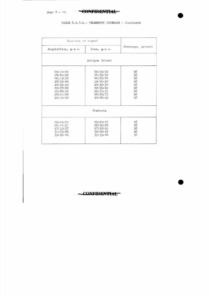
8/7/2019 Post Launch Memorandum Report for Mercury-Atlas No. 9(MA-9). Part 1 Mission Analysis
http://slidepdf.com/reader/full/post-launch-memorandum-report-for-mercury-atlas-no-9ma-9-part-1-mission 307/344
Page 40 • C O N F I D E N T I A L
TABLE 8.2.4-1.- TELEMETRY COVERAGE - Concluded
Duration of signal
Acquisition, g. e. t. Loss, g. e.t.Coverage, percent
Antigua Island
05:12:5304:45:22
06:19:5218:59:40
20:32:10
22:07:00
26:48:5028:21:20
29:55:50
03:13:3004:52:30
06:25:2419:05:20
20:39:30
22:11: 40
26:54:3528:23:1530:00:29
989898989898989898
Pretoria
02:05:50
06:44:25
27:12:37
31: 53: 2033:26:46
03:10:3706:52:20
27:18:2632:02:07
33:33:00
9898989898
fflFIDEMTIAL-
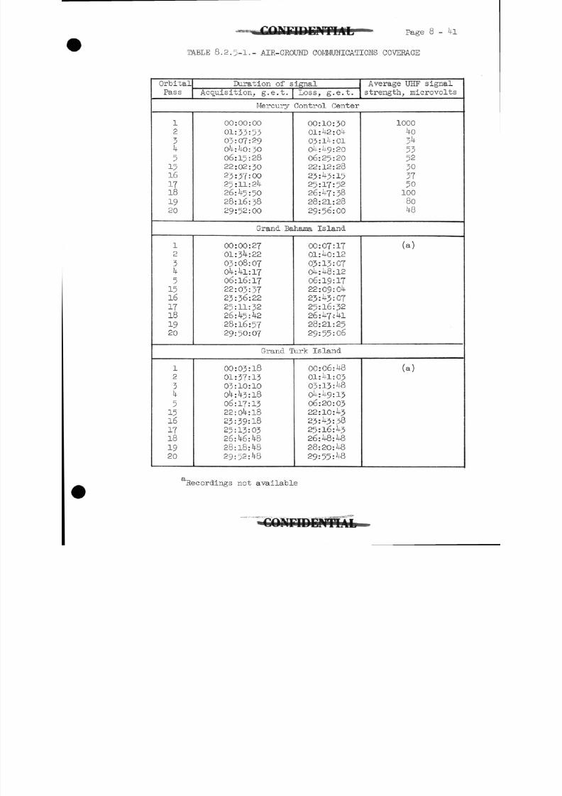
8/7/2019 Post Launch Memorandum Report for Mercury-Atlas No. 9(MA-9). Part 1 Mission Analysis
http://slidepdf.com/reader/full/post-launch-memorandum-report-for-mercury-atlas-no-9ma-9-part-1-mission 308/344
Page 8 - 4l
TABLE 8.2.5-1.- AIR-GROIMD COMMUNICATIONS COVERAGE
OrbitalPass
Duration of signal
Acquisition, g.e.t. Loss, g.e.t.
Average UHF signal
strength, microvolts
Mercury Control Center
1
2
34515161718
1920
00:00:00
01:33:5303:OT:2904:40:3006:15:28
22:02:30
23:37:0025:11:24
26:45:50
28:16:38
29:52:00
00:10:3001: 42 : 04
03:14:01
04:49:20
06:25:20
22:12:28
23:43:1525:17:52
26:47:3828:21:28
29:56:00
1000
40
345352303T501008048
Grand Bahama Island
12
34
51516
IT181920
00:00:27
01:34:22
03:08:0704:41:1706: 16: 17
22:03:3T23:36:22
25:11:3226 : 45 : 42
28:l6:5T
29:50:07
00:07:1701:40:12
03:13:0704:48:12
06:19:1722:09:04
23 : 43 : 07
25:16:3226:47-:4l
28:21:25
29:55:06
(a)
Grand Turk Island
1
2
3
5
1516IT18
1920
00:03:18
01:37:1303:10:10
04:43:18
06:17:13
22:04:1823:39:18
25:13:0326:46:4828:18:48
29:52:48
00:06:48
01:41:0303:13:48
04:49:13
06:20:03
22:10:4323:43:38
25:16:43
26:48:4828:20:48
29:55:48
(a)
Recordings not available
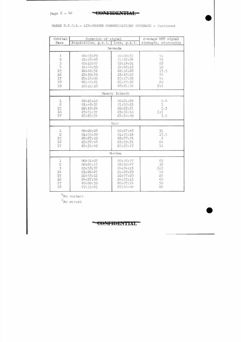
8/7/2019 Post Launch Memorandum Report for Mercury-Atlas No. 9(MA-9). Part 1 Mission Analysis
http://slidepdf.com/reader/full/post-launch-memorandum-report-for-mercury-atlas-no-9ma-9-part-1-mission 309/344
Page 8 - 4 2
T A B L E 8.2.5-1.- A I R - G R O U N D C O M M U N I C A T I O N S C O V E R A G E - Continued
Orbital
Pass
Duration of signal
Acquisition, g.e.t. Loss, g.e.t.
Average UEF signal
strength, microvolts
Bermuda
12
34
1516171819
00:03:29
01:36:4803:10:27
04:44:39
22:06:52
23:39:5925:14:00
26:46:23
28:21:28
00:09:3301 : 42 : 0403:14:0104:48:1322:12:28
23:43:15
25:17:52
26:47:38
28:21:30
41
702812
17-5804l
29(*)
Canary Islands
12
1516IT
00:15:10
01:48:3522:18:24
23:51:3725:25:54
00:21:20
01:50:23
22:23:31
23:56:1025:30:09
5.4l5 - 3
(c)
3 - 5
Kano
1
2
1516
17
00:22:28
01:55:0922:27:09
23:57:4825:31:49
00:27:48
01:55:1422:27:54
23:59:3125:35:17
3117-5624
11
Muchea
12
31415161718
00:51:0702:24:17
03:58:3721:22:27
22:53:12
24:27:36
26:00:39
27:33:23
00:56:5702:30:47
04:04:1321:26:29
22:57:20
24:33:1326:07:14
27:40:00
6038
(c)4o
25605022
bWo contact
'No record
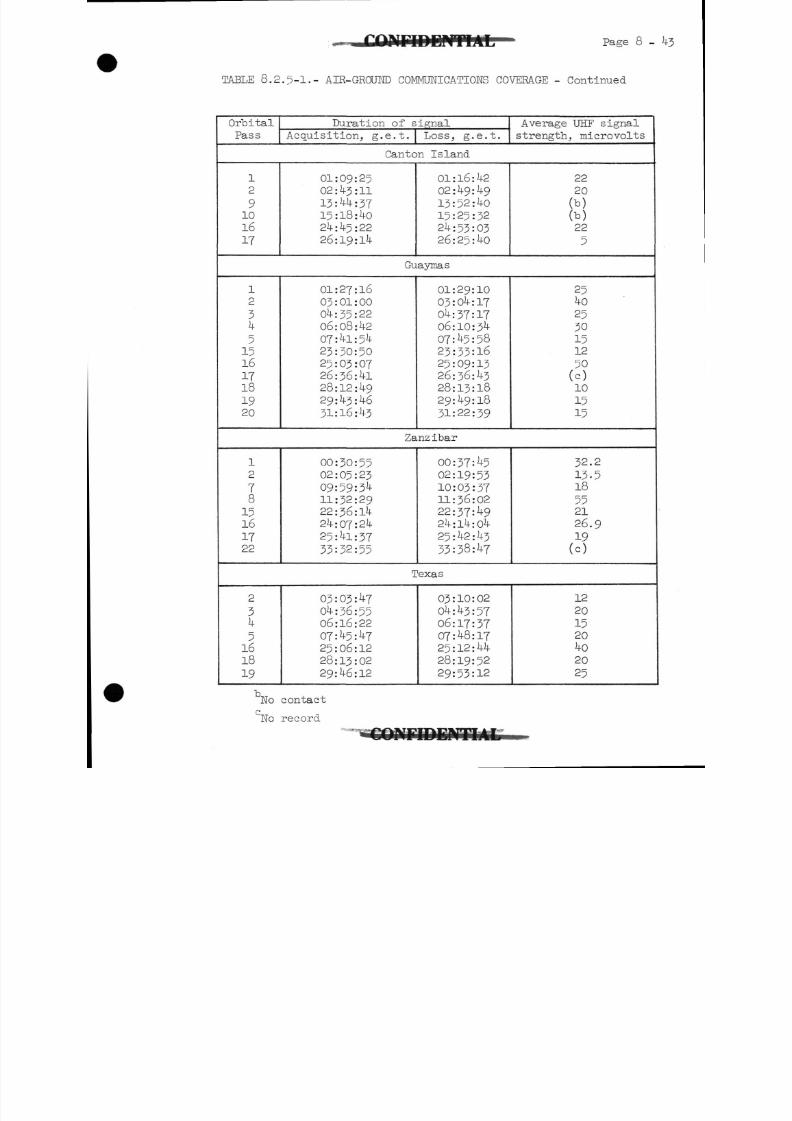
8/7/2019 Post Launch Memorandum Report for Mercury-Atlas No. 9(MA-9). Part 1 Mission Analysis
http://slidepdf.com/reader/full/post-launch-memorandum-report-for-mercury-atlas-no-9ma-9-part-1-mission 310/344
Page 8 - 4 3
' TA B LE 8.2.5-1.- A I R - G R O U N D C O M M U N I C A T I O N S C O V E R A G E - Continued
Orbital
Pass
Duration of signal
Acquisition, g.e.t. Loss, g.e.t.
Average UEF signal
strength^ microvolts
Canton Island
12
910
16
17
01:09:25
02:43:11
13:44:3715:18:4024:45:22
26:19:14
01:16:42
02:49:49
13:52:40
15:25:3224:53:0326:25:40
22
20
(b)(b)22
5
Guaymas
12
34
515161718
1920
01:27:1603:01:00
04:35:22
06:08:42
07:4l:5423:30:50
25:03:0726:36:41
28:12:49
29:43:46
31:16:43
01:29:1003:04:17
04:37:17
06:10:34
07:45:5823:33:16
25:09:1326:36:43
28:13:18
29:49:18
31:22:39
254o
2530
151250(c)10
1515
Zanzibar
12
78
1516
1722
00:30:5502:05:23
09:59:511:32:29
22:36:14
24:07:24
25:41:37
33:32:55
00:37: 5
02:19:53
10:03:3711:36:02
22:37:49
24:14:04
25:42:43
33:38:47
32.2
1 3 - 5185521
26.9
19(c)
Texas
2
31 *
51618
19
03:03:47
04:36:5506:16:22
07:45:47
25:06:12
28:13:02
29:46:12
03:10:02
04:43:57
06:17:3707:48:17
25:12:44
28:19:52
29:53:12
12
20
15204020
25
Wo contact
"No record
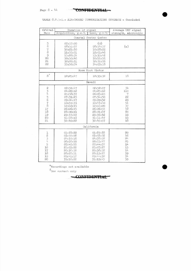
8/7/2019 Post Launch Memorandum Report for Mercury-Atlas No. 9(MA-9). Part 1 Mission Analysis
http://slidepdf.com/reader/full/post-launch-memorandum-report-for-mercury-atlas-no-9ma-9-part-1-mission 311/344
Page 8 - 44 E K T I A L
TABLE 8.2.5-1.- AIR-GROUND COMMUNICATIONS COVERAGE - Concluded
Orbital
Pass
Duration of signal
Acquisition, g.e.t. | Loss, g.e.t.
Average UHF signal
strength, microvolts
Coastal Sentry Quebec
56
18
92021
22
07:17:20
08:51:3710:21:30
11:55:01
13:28:34
30:50:4632:22:31
33:56:5
(a )08:5 :5710:28:22
12:01:46
13:35: 2
30:51:5632:31:06
34:03:18
(a)
Rose Knot Victor
8" 12:25:47 12:33:32 18
Hawaii
2
34
56
7
81718
1920
21
02:51:4704:22:12
05:58:37
07:31:2509:0 :17
10:37:33
12:10:1526:26: -5
28:00:11
29:33: 7
31:07:1732:40:22
02:52:17
04:25:12
06:05:15
07:3 :50
09:09:52
10:43:40
12:14:2026:26:54
28:01:47
29:36:42
31:11:47
32:45:57
34110
722
29
51
374880
191918
California
12
3
4516
1718
1920
01:28:22
03:00:02
0 :33:16
06: 06: 0007: 0:5525 : 03 : 2226:36:32
28:07:5129:41:17
31:16:22
01:29:22
03:05:02
04:37:02
06:11:4707:44:0?25:07:27
26:38:12
28:13:27
29:44:32
31:19: 5
20
1624
2514
1514
393^30
Recordings not available
One contact only
8/7/2019 Post Launch Memorandum Report for Mercury-Atlas No. 9(MA-9). Part 1 Mission Analysis
http://slidepdf.com/reader/full/post-launch-memorandum-report-for-mercury-atlas-no-9ma-9-part-1-mission 312/344
EH~* Page 9-1
9.0 RECOVERY
9-1 Recovery Plans
The areas where recovery ships and aircraft were positioned in the
Atlantic and Pacific Oceans are shown in figure 9-l-l(a) and figure
9-l-l(b), respectively. Recovery capability was provided in areas A
through F in the event that it became necessary to abort the mission
during powered flight. Areas 2-1 through 21-1 were areas in which the
spacecraft could have landed if the flight were terminated earlier than
planned. These areas were spaced so that the spacecraft would pass
over one of them approximately every 90 minutes, or about once per orbital
pass. Area 22-1, which was the primary planned landing area for a nom-
inal flight of 3 - hours and 20 minutes, was located approximately 70
nautical miles southeast of Midway Island.
Recovery forces were deployed within these planned landing areas so"
that recovery and assistance could be provided within 3 to 9 hours after
spacecraft landing. This "access time" varied for the different areas
and was based on the probability of a spacecraft landing within a given
area and the planned deployment of recovery forces in that area. Selec-
tion of landing areas at spacecraft ground-track intersections permitted
a unit to move from one area to another and thereby provide a recovery
capability in several landing areas. A total of 23 ships and kk aircraft
were employed in the MA-9 recovery operation, of which 12 ships and 26 air-
craft were in the Atlantic landing areas and 11 ships and 18 aircraft were
in the Pacific. Table 9-1-1 indicates the number of ships and aircraft
on station at the various landing areas, their movements from one area toanother, and the access time for each area. Additional search aircraft
were available as back-ups to the aircraft on station. Also, helicopters,
amphibious surface vehicles, and small boats were positioned for recovery
support near the launch complex.
Contingency recovery aircraft and personnel were on alert status at
staging bases around the world to provide support in the event a landing
should occur at any place along the orbital ground track. These aircraft
were equipped to locate the spacecraft and to provide emergency on-the-
scene assistance if required. A typical support unit at a staging base
consisted of 2 or 3 long-range aircraft and pararescue personnel.
The locations of these staging bases are as follows:
Patrick Air Force Base, Florida Singapore, Malaya
Kindley Air Force Base, Bermuda Clark Air Force Base, Philippines
Lajes Air Force Base, Azores Waha, Okinawa
Nouasseur, Morocco Tachikawa, Japan
Wheelus Air Force Base, Libia Andersen Air Force Base, Guam
Kano, Nigeria Perth, Australia
Aden Protectorate Townsville, Australia
C O M F 1 D E M T M L
8/7/2019 Post Launch Memorandum Report for Mercury-Atlas No. 9(MA-9). Part 1 Mission Analysis
http://slidepdf.com/reader/full/post-launch-memorandum-report-for-mercury-atlas-no-9ma-9-part-1-mission 313/344
Page 9-2
Nairobi, Kenya Midway Island
Salisbury, Rhodesia Kwajalein Island
Mauritius Island Wandi, Fiji Islands
Ascension Island Hickam Air Force Base, Hawaii
Trinidad Island Johnston Island
Lima, Peru Papeete, Tahiti
Galapagos Islands San Diego, California
9-2 Recovery Operations
All recovery forces were on station at launch time and moved to
planned positions as the mission progressed. Weather conditions were
favorable for spacecraft location and retrieval in all planned andcon-
tingency areas throughout the mission.
A communications network linked the deployed recovery forces to the
recovery room of the Mercury Control Center at Cape Canaveral. Recovery
communications were good throughout the entire operation and the recovery
forces were informed of mission status during all phases of the flight.
At an appropriate time, recovery units were informed that the flight
would proceed to normal completion, and the expected retrorocket ignition
time of 33:59:30 for landing area 22-1 was transmitted. At about 34:04:00,
approximately l6 minutes prior to landing, recovery forces in area 22-1
were informed that the retrorockets had ignited normally and that the
landing position was predicted to be 2T°23rNorth latitude and 176°30' West
longitude. This information was transmitted as CALREP 1 (calculated land-
ing position report) to the recovery forces from the Recovery Coordinator
in the Mercury Control Center.. Recovery units in the area made contact
with the descending spacecraft before any additional predicted landing po-
sitions, based on reentry tracking, were made available from network support.
At about 34:12:00 the U.S.S. Kearsarge, the aircraft carrier positioned in
the center of area 22-1, reported radar contact with the spacecraft at a
slant range of l80 nautical miles and held contact until shortly before
spacecraft landing. A "sonic boom," similar to that heard during the
MA-8 reentry, was detected by recovery ship personnel. Personnel aboard
the U. S. S. Kearsarge reported first visual contact with the spacecraft as
it descended on the main parachute at an altitude of about 8,000 feet.
(See fig. 9.2-1.) The spacecraft landed at approximately 34:20:00 at27°22.6' North latitude, 176°35.3' West longitude, which corresponded to
a position approximately 4.4 nautical miles uprange of the recovery ship.
Weather conditions in the recovery area are listed in section 10.3.
Helicopters had been launched from the U.S.S. Kearsarge 15 minutes
prior to spacecraft landing and were in an excellent position to deploy
swimmers immediately. These swimmers quickly installed the auxiliary
flotation collar around the spacecraft. Helicopter pilots and swimmers
1M.J\Li
8/7/2019 Post Launch Memorandum Report for Mercury-Atlas No. 9(MA-9). Part 1 Mission Analysis
http://slidepdf.com/reader/full/post-launch-memorandum-report-for-mercury-atlas-no-9ma-9-part-1-mission 314/344
Page 9-3
in the landing area reported that the spacecraft, Immediately after land-ing, was floating on its side and gradually righted itself soon after mainparachute release, which was estimated to have occurred about JO secondsafter landing. Four minutes after landing, the astronaut reported thathe would remain in the spacecraft and await retrieval "by the recovery ship.
The antenna canister landed within 600 feet of the spacecraft but sankbefore the back-up swimmers could attempt retrieval. The ejected reserveparachute was retrieved by the swimmers. At about 5k:k6:OQ as the U. S. S.Kearsarge approached within 600 feet of the spacecraft, a motor whaleboat(shown in fig. 9.2-2) attached a lifting line to the recovery loop of thespacecraft. The spacecraft was then brought alongside the ship, liftedclear of the water, and placed on the no. 3 elevator of the recoverycarrier at 3 t56:00. The explosive -actuated hatch was released, as shownin figure 9-2-3, by using the external release lanyard. At about 35sOlsOO>doctors began examining the astronaut and taking blood-pressure measure-ments. The astronaut egressed from the spacecraft kQ minutes after landingat 35:08:00. (See fig. 9.2- .) He remained onboard the Kearsarge for a
period of examination, rest, and debriefing.
There was no apparent damage to the spacecraft at the time of landing.The swimmers who attached the auxiliary flotation collar to the spacecraftreported that none of the heat -shield straps were broken and damage tothe landing bag consisted of several small vertical tears. However, whilethe spacecraft was being lifted aboard the carrier, the UHF descent andrecovery antenna was broken loose at the hinge point. In addition, whenthe explosive -actuated hatch was released, the spacecraft window wasbroken.
Certain spacecraft onboard equipment was removed immediately after
recovery and flown to Cape Canaveral. Two days after recovery, the space-craft was transferred from the recovery ship to a truck at Pearl Harbor NavalBase. Prom there, it was taken to Hickam Air Force Base, loaded aboard aC-130 aircraft, and delivered to Cape Canaveral the next day.
9 - 3 Recovery Aids
Prior to spacecraft landing, telemetry aircraft established contactbefore and after communications blackout, and radar tracking aircraftmaintained contact during most of the blackout period.
All spacecraft visual and electronic recovery aids were reported tohave been operating normally. Helicopters reported that the dye markerpresented a brilliant green visual target which could be observed from adistance of 500 yards. The flashing light was reported as operatingnormally by on-scene observers.
8/7/2019 Post Launch Memorandum Report for Mercury-Atlas No. 9(MA-9). Part 1 Mission Analysis
http://slidepdf.com/reader/full/post-launch-memorandum-report-for-mercury-atlas-no-9ma-9-part-1-mission 315/344
p a g e 9 - ooinrroraiTLiL
The HF/DF- stations in Midway Island and San Francisco, California,
received, spacecraft • HF transmissions after landing and determined the
landing position within approximately JO nautical miles of the actual
retrieval point, as shown in figure 9- 3-1-
The telemetry and search aircraft reported contact with and verifiedthe operation of both spacecraft SARAH beacons. Acquisition ranges re-
ported by these aircraft were as great as 270 nautical miles.
Stations reporting fixes from the SOFAR-bomb detonation determined
the landing position within 10 nautical miles. A quick fix was provided
approximately 20 minutes after landing. Post-landing details of area 22-1
are illustrated in figure 9-3-1-
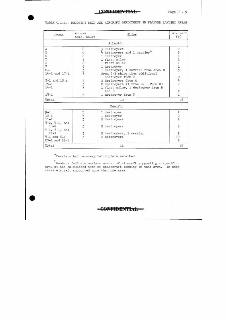
8/7/2019 Post Launch Memorandum Report for Mercury-Atlas No. 9(MA-9). Part 1 Mission Analysis
http://slidepdf.com/reader/full/post-launch-memorandum-report-for-mercury-atlas-no-9ma-9-part-1-mission 316/344
Page 9-5
TABLE 9.1-1.- RECOVERY SHIP AND AIRCRAFT DEPLOYMENT IN PLANNED LANDING AREAS
AreasAccess
time, hoursShips
Aircraft
Cb)
Atlantic
A
BCD
E
F
2-1
16-1 and 17-1
3-1 and 18-1
15-1
1*41
13-1
69636633
333
5
3 destroyers
4 destroyers and 1 carrier
1 destroyer
1 fleet oiler
1 fleet oiler
1 destroyer
1 destroyer, 1 carrier from area B
Area 2-1 ships plus additional
destroyer from B
2 destroyers from A
2 destroyers (l from B, 1 from C)1 fleet oiler, 1 destroyer from D
and E
1 destroyer from F
2
311113
9k
2
21
Total 12 26
Pacific
9-110-1
11-1
3-2, 8-1, and
18-2
-1, 7-1, and
22-1
5-1 and 6-1
20-1 and 21-1
553
3
33
1 destroyer
1 destroyer
2 destroyers
2 destroyers
2 destroyers, 1 carrier
2 destroyers
2
2
2
2
2
122
Total 11 18
Carriers had recovery helicopters embarked.
Numbers indicate maximum number of aircraft supporting a specific
area at the calculated time of spacecraft landing in that area. In somecases aircraft supported more than one area.
C O M T D D P i T I A L
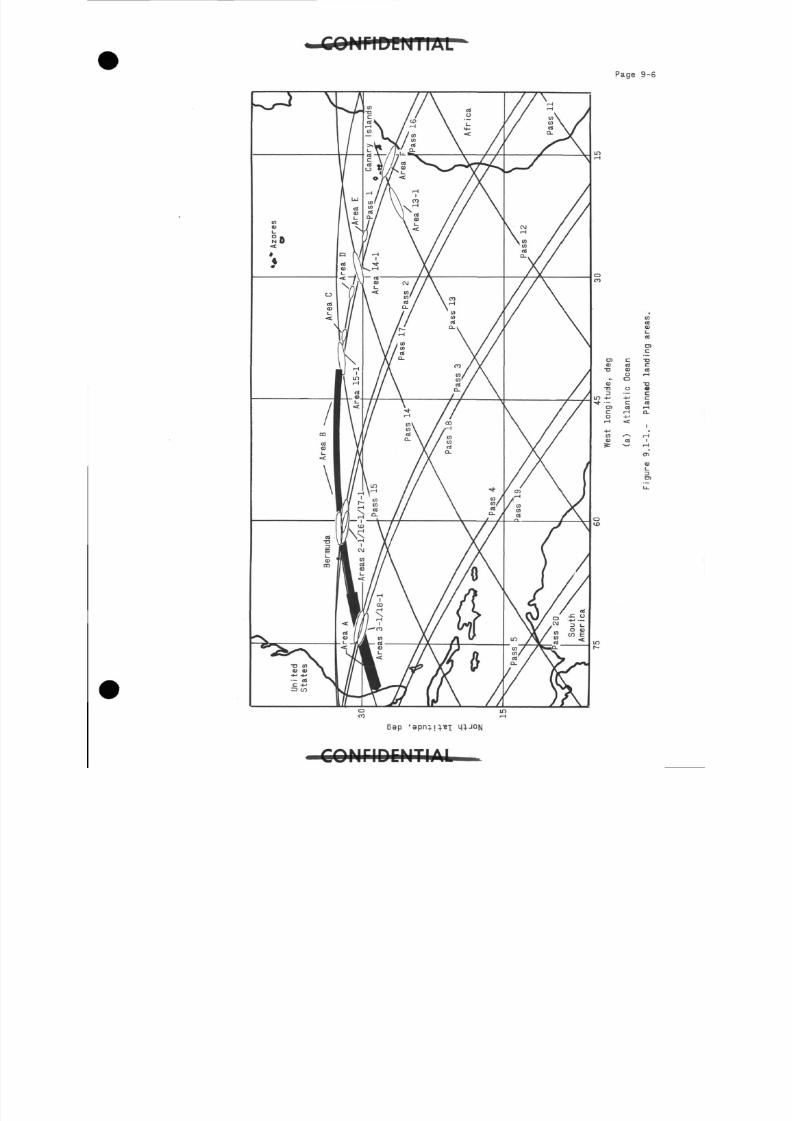
8/7/2019 Post Launch Memorandum Report for Mercury-Atlas No. 9(MA-9). Part 1 Mission Analysis
http://slidepdf.com/reader/full/post-launch-memorandum-report-for-mercury-atlas-no-9ma-9-part-1-mission 317/344
P a g e 9 - 6
A i
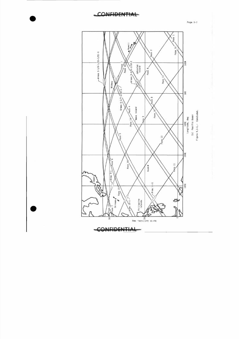
8/7/2019 Post Launch Memorandum Report for Mercury-Atlas No. 9(MA-9). Part 1 Mission Analysis
http://slidepdf.com/reader/full/post-launch-memorandum-report-for-mercury-atlas-no-9ma-9-part-1-mission 318/344
P a g e 9- 7
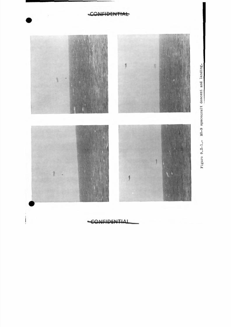
8/7/2019 Post Launch Memorandum Report for Mercury-Atlas No. 9(MA-9). Part 1 Mission Analysis
http://slidepdf.com/reader/full/post-launch-memorandum-report-for-mercury-atlas-no-9ma-9-part-1-mission 319/344
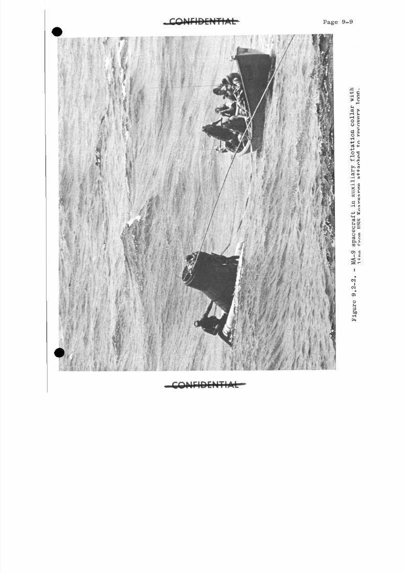
8/7/2019 Post Launch Memorandum Report for Mercury-Atlas No. 9(MA-9). Part 1 Mission Analysis
http://slidepdf.com/reader/full/post-launch-memorandum-report-for-mercury-atlas-no-9ma-9-part-1-mission 320/344
Page 9
..
IJy
;
j.
•m•**'
t K . ^
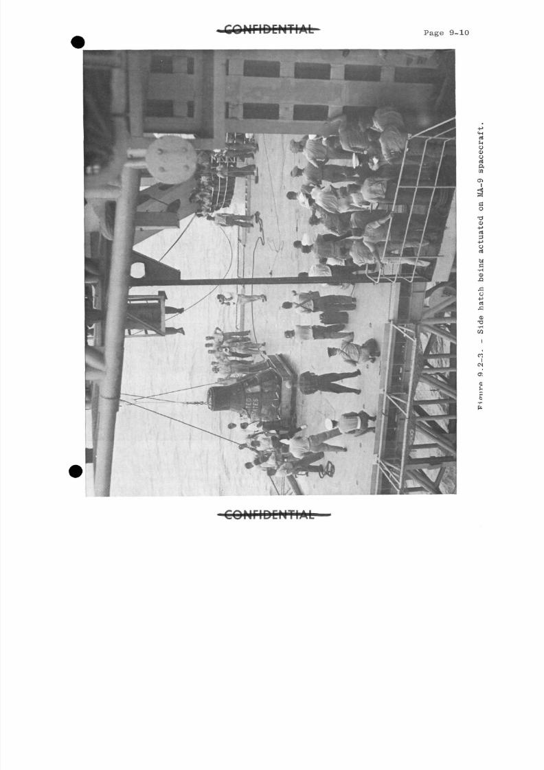
8/7/2019 Post Launch Memorandum Report for Mercury-Atlas No. 9(MA-9). Part 1 Mission Analysis
http://slidepdf.com/reader/full/post-launch-memorandum-report-for-mercury-atlas-no-9ma-9-part-1-mission 321/344
C O N F I D E N T I Page 9-1
C O N F I D E N T I A L
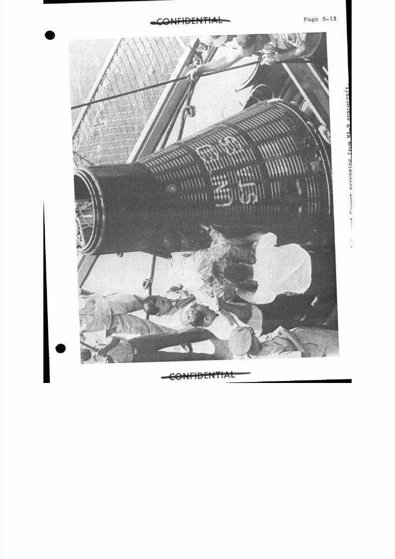
8/7/2019 Post Launch Memorandum Report for Mercury-Atlas No. 9(MA-9). Part 1 Mission Analysis
http://slidepdf.com/reader/full/post-launch-memorandum-report-for-mercury-atlas-no-9ma-9-part-1-mission 322/344
Page 9-11
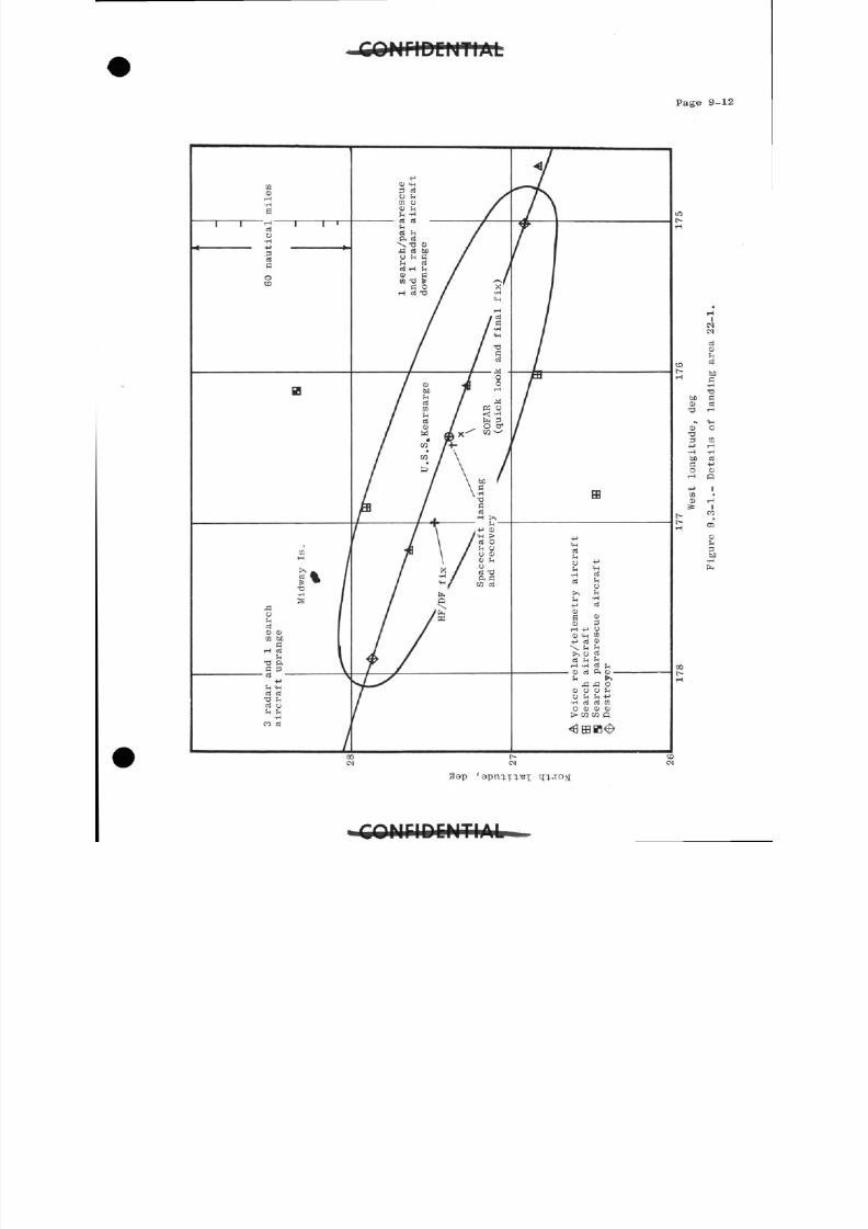
8/7/2019 Post Launch Memorandum Report for Mercury-Atlas No. 9(MA-9). Part 1 Mission Analysis
http://slidepdf.com/reader/full/post-launch-memorandum-report-for-mercury-atlas-no-9ma-9-part-1-mission 323/344
Page 9-12
S a p '
8/7/2019 Post Launch Memorandum Report for Mercury-Atlas No. 9(MA-9). Part 1 Mission Analysis
http://slidepdf.com/reader/full/post-launch-memorandum-report-for-mercury-atlas-no-9ma-9-part-1-mission 324/344
Page 10-1
10.0 APPENDIX A
10.1 Spacecraft History
Spacecraft 20 arrived at Cape Canaveral, Florida, on October 9>1962. The preparation period for the spacecraft and the individualonboard systems and equipment was slightly different from that ofprevious spacecraft in that an integrated systems test was made priorto the normal individual system tests. This sequence of testing waspossible because of the extensive individual spacecraft systems testswhich had been performed by the spacecraft contractor. The number
of work days in the hangar totaled 170 days, of which 59^ days were
spent on formal tests. There were 6ll Mission Preparation Sheets (MPS),
which authorize specifically required work, and 62^ DiscrepancyReports (DR), which describe items requiring rework.
The spacecraft was transported to the launch site and mated with
the launch vehicle on April 22, 19&3-
The major prelaunch tests, modifications, and events in thehistory of spacecraft 20 at Cape Canaveral are shown in chronological
order in the following table:
A ¥
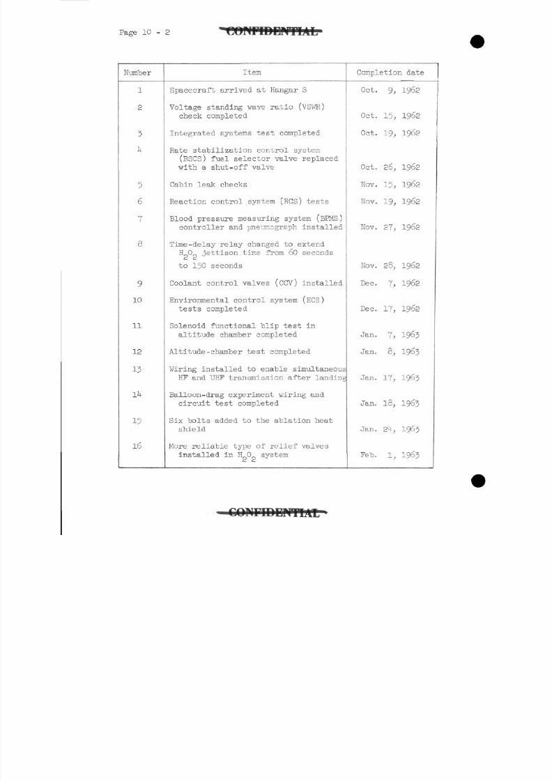
8/7/2019 Post Launch Memorandum Report for Mercury-Atlas No. 9(MA-9). Part 1 Mission Analysis
http://slidepdf.com/reader/full/post-launch-memorandum-report-for-mercury-atlas-no-9ma-9-part-1-mission 325/344
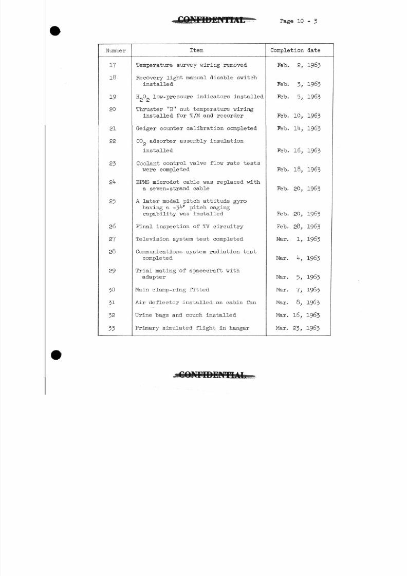
8/7/2019 Post Launch Memorandum Report for Mercury-Atlas No. 9(MA-9). Part 1 Mission Analysis
http://slidepdf.com/reader/full/post-launch-memorandum-report-for-mercury-atlas-no-9ma-9-part-1-mission 326/344
Page 1 0- 3
Number
17
18
19
20
21
22
23
2U
25
26
27
28
29
30
3 132
33
Item
Temperature survey wiring removed
Recovery light manual disable svitch
installed
HO low-pressure indicators installed
Thruster "B" nut temperature wiring
installed for T/M and recorder
Geiger counter calibration completed
CO adsorber assembly insulation
installed
Coolant control valve flow rate tests
were completed
BPMS microdot cable was replaced with
a seven- strand cable
A later model pitch attitude gyro
having a -3 -° pitch caging
capability was installed
Final inspection of TV circuitry
Television system test completed
Communications system radiation test
completed
Trial mating of spacecraft with
adapter
Main clamp-ring fitted
Air deflector installed on cabin fan
Urine bags and couch installed
Primary simulated flight in hangar
Completion date
Feb. 2, 1963
Feb. 3, 1963
Feb. 5, 1963
Feb. 10, 1963
Feb. lU, 1963
Feb. 16, 1963
Feb. 18, 1963
Feb. 20, 1963
Feb. 20, 1963
Feb. 28, 1963
Mar. 1, 1963
Mar. k, 1963
Mar. 5, 1963
Mar. 7, 1963
Mar. 8, 1963
Mar. 16, 1963
Mar. 23, 1963
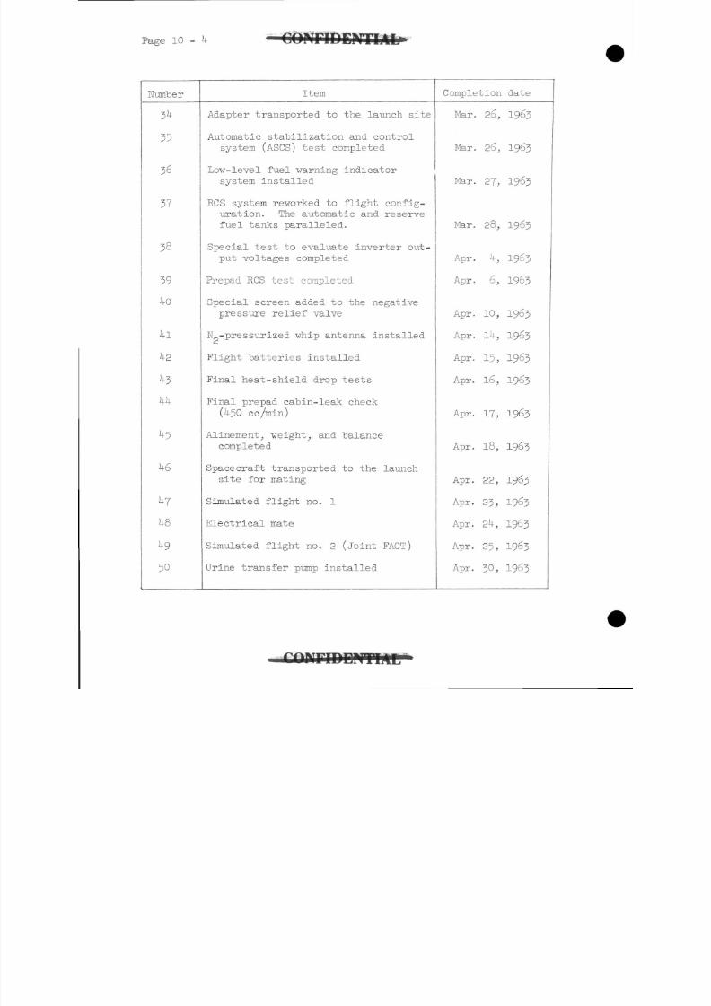
8/7/2019 Post Launch Memorandum Report for Mercury-Atlas No. 9(MA-9). Part 1 Mission Analysis
http://slidepdf.com/reader/full/post-launch-memorandum-report-for-mercury-atlas-no-9ma-9-part-1-mission 327/344
Page 10 - I V F I D E P r T L I L
Number Item Completion date
35
36
37
38
39
i n
50
Adapter transported to the launch site
Automatic stabilization and controlsystem (ASCS) test completed
Low-level fuel warning indicatorsystem installed
ECS system reworked to flight config-uration. The automatic and reservefuel tanks paralleled.
Special test to evaluate inverter out-
put voltages completed
Prepad RCS test completed
Special screen adde d to the negativepressure relief valve
N -pressurized whip antenna installed
Flight batteries installed
Final heat-shield drop tests
Final prepad cabin-leak check(i+50 cc/min)
Alinement, weight, and balancecompleted
Spacecraft transported to the launchsite for mating
Simulated flight no. 1
Electrical mate
Simulated flight no. 2 (Joint FACT)
Urine transfer pump installed
Mar. 26, 1963
Mar. 26, 1963
Mar. 27, 1963
Mar. 28, 1963
Apr. h, 1963
Apr. 6, 1963
Apr. 10, 1963
Apr. 1 * 4 - , 1963
Apr. 15, 1963
Apr. 16, 1963
Apr. 17, 1963
Apr. 18, 1963
Apr. 22, 1963
Apr. 23, 1963
Apr. 2U, 1963
Apr. 25, 1963
Apr. 30, 1963
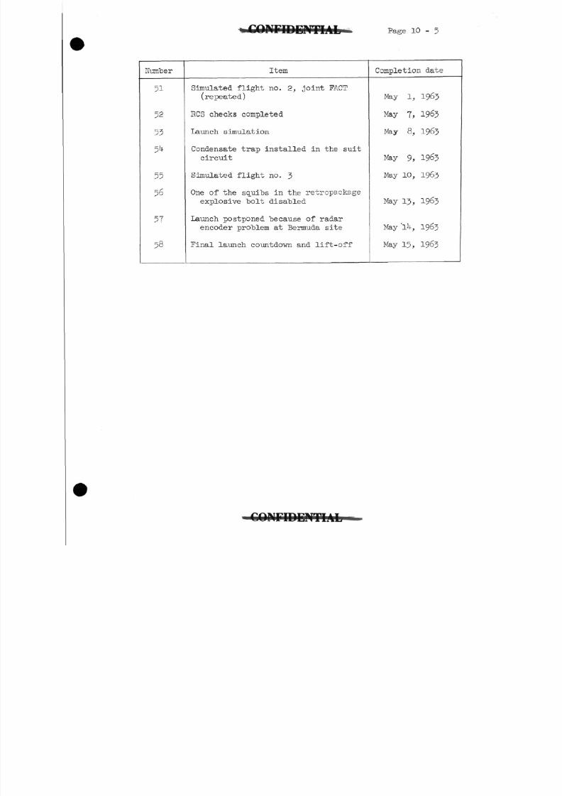
8/7/2019 Post Launch Memorandum Report for Mercury-Atlas No. 9(MA-9). Part 1 Mission Analysis
http://slidepdf.com/reader/full/post-launch-memorandum-report-for-mercury-atlas-no-9ma-9-part-1-mission 328/344
K F I D E K T I A L Page 10-5
Number
51
52
53
5U
55
56
57
58
Item
Simulated flight no. 2., joint FACT(repeated)
RCS checks completed
Launch simulation
Condensate trap installed in the suit
circuit
Simulated flight no. J
One of the squibs in the retropackage
explosive bolt disabled
Launch postponed because of radar
encoder problem at Bermuda site
Final launch countdown and lift-off
Completion date
May 1, 1963
May 1, 1963
May 8, 1963
May 9, 1963
May 10, 1963
May 13, 1963
May 'Ik, 1963
May 15, 1963
M F I D E P O I A L
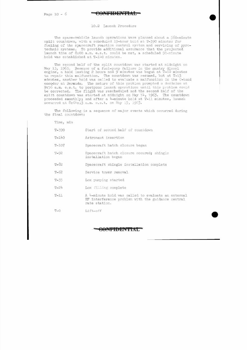
8/7/2019 Post Launch Memorandum Report for Mercury-Atlas No. 9(MA-9). Part 1 Mission Analysis
http://slidepdf.com/reader/full/post-launch-memorandum-report-for-mercury-atlas-no-9ma-9-part-1-mission 329/344
1 0 - 6 • C O N F I D E N T I A L
10.2 Launch Procedure
The space-vehicle launch operations were planned about a 560-minute
split countdown, with a scheduled 19-hour hold at T-390 minutes for
fueling of the spacecraft reaction control system and servicing of pyro-technic systems. To provide additional assurance that the projected
launch time of 8:00 a.m. e.s.t. could be met, a scheduled 90-minute
hold was established at T-l4o minutes.
The second half of the split countdown was started at midnight on
May 13, 1963- Because of a fuel-pump failure in the gantry diesel
engine, a hold lasting 2 hours and 9 minutes was begun at T-60 minutes
to repair this malfunction. The countdown was resumed, but at T-13
minutes, another hold was called to evaluate a malfunction in the C-band
encoder at Bermuda-. The nature of this problem prompted a decision at
9:56 a.m. e.s.t. to postpone launch operations until this problem could
be corrected. The flight was rescheduled and the second half of thesplit countdown was started at midnight on May lk, 1963. The countdown
proceeded smoothly; and after a ^--minute hold at T-ll minutes, launch
occurred at 8:0 -:13 a.m. e.s.t. on May 15, 19 3-
The following is a sequence of major events which occurred during
the final countdown:
Time, min
T-390 Start of second half of countdown
T-l4o Astronaut insertion
T-107 Spacecraft hatch closure began
T-92 Spacecraft hatch closure secured; shingle
installation began
T-82 Spacecraft shingle installation complete
T-62 Service tower removal
T-35 Lox pumping started
T-24 Lox filling complete
T-ll A ^--minute hold was called to evaluate an external
KF interference problem with the guidance central
rate station.
T-0 Lift-off
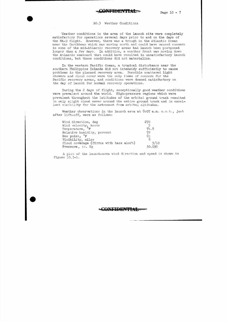
8/7/2019 Post Launch Memorandum Report for Mercury-Atlas No. 9(MA-9). Part 1 Mission Analysis
http://slidepdf.com/reader/full/post-launch-memorandum-report-for-mercury-atlas-no-9ma-9-part-1-mission 330/344
Page 10-7
10.3 Weather Conditions
Weather conditions in the area of the launch site vere completely
satisfactory for operations several days prior to and on the days of
the MA.-9 flight. However, there was a trough in the Atlantic Oceannear the Caribbean which was moving north and could have caused concern
in some of the mid-Atlantic recovery areas had launch been postponed
longer than a few days. In addition, a weather front was moving down
the Atlantic seaboard that could have resulted in unsatisfactory launch
conditions, but these conditions did not materialize.
In the western Pacific Ocean, a tropical disturbance near the
southern Philippine Islands did not intensify sufficiently to cause
problems in the planned recovery area. Possible scattered light
showers and cloud cover were the only items of concern for the
Pacific recovery areas, and conditions were deemed satisfactory on
the day of launch for normal recovery operations.
During the 2 days of flight, exceptionally good weather conditions
were prevalent around the world. High-pressure regions which were
prevalent throughout the latitudes of the orbital ground track resulted
in only slight cloud cover around the entire ground track and in excel-
lent visibility for the astronaut from orbital altitudes.
Weather observations in the launch area at 8:07 a.m. e.s.t., just
after lift-off, were as follows:
Wind direction, deg 270
Wind velocity, knots 5Temperature, °F 7 .8
Relative humidity, percent J2
Dew point, °F 65
Visibility, miles 8
Cloud coverage (Cirrus with haze aloft) 5/10
Pressure, in. Hg 30.095
A plot of the launch-area wind direction and speed is shown in
figure 10.3-1.
K r i D E P F T I A L
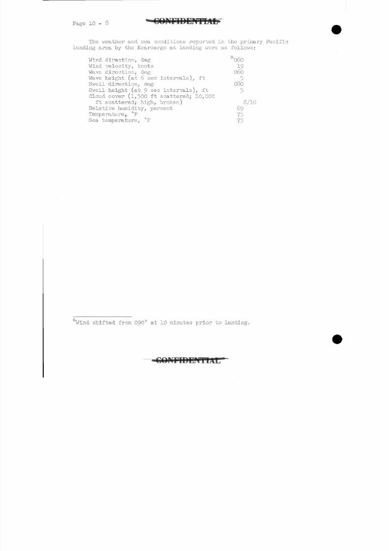
8/7/2019 Post Launch Memorandum Report for Mercury-Atlas No. 9(MA-9). Part 1 Mission Analysis
http://slidepdf.com/reader/full/post-launch-memorandum-report-for-mercury-atlas-no-9ma-9-part-1-mission 331/344
Page 10 - C O N F I D E N T I A L
The weather and sea conditions reported in the primary Pacific
landing area by the Kearsarge at landing were as follows:
Wind direction,, deg 060
Wind velocity, knots 19
Wave direction, deg 060Wave height (at 6 sec intervals), ft
Swell direction, deg 080
Swell height (at 9sec
intervals), ft
Cloud cover (l,500 ft scattered; 10,000
ft scattered; high, broken) 8/10
Relative humidity, percent 69
Temperature, °F 75
Sea temperature, °F 75
Wind shifted from 090° at 10 minutes prior to landing.
8/7/2019 Post Launch Memorandum Report for Mercury-Atlas No. 9(MA-9). Part 1 Mission Analysis
http://slidepdf.com/reader/full/post-launch-memorandum-report-for-mercury-atlas-no-9ma-9-part-1-mission 332/344
Page 10-9
10.h Flight Safety Review
Flight safety and mission review meetings were conducted to determine
the flight worthiness of the MA-9 spacecraft and launch vehicle and to
ascertain the readiness of all supporting elements for the MA-9 mission.
10.h.I Spacecraft.- As a result of the systems changes necessitated by
the extended mission, flight safety review meetings were held
after the completion of the RCS and ECS systems tests and after
the primary simulated flight in the hangar. The meeting on the
RCS system was held on November 29, 19 2, and, for that stage of
checkout and preparation, the system was found to be capable of
performing,'its intended mission. The meeting on the ECS system
was held on February 5, 19&3, and no problems other than those
already in the process of being resolved were noted. Again, for
that stage of checkout and preparation, the system was found to
be capable of performing it's mission. A review of the spacecraft
systems following the primary simulated flight was held onApril 9, 1963?
arid all problems encountered were discussed and
direction for corrective action was given. At the spacecraft
flight safety review held on May 9, 196j, all systems were
approved as ready for flight, pending the successful completion
of the final simulated flight test, which was satisfactorily
completed on May 10, 1963.
10. U. 2 Launch vehicle.- Several meetings were held to determine the stat
of the Atlas IJOD launch vehicle. The first meeting was conducted
on April 22, 1963, to review the nature and the solutions of the
problems in the flight control system that had caused the late
delivery of the launch vehicle to the Atlantic Missile Range.Satisfactory resolution had been obtained on all problems. The
regular launch-vehicle review meeting was held at 9'00 a.m. e.s.t.
on May 11, 1963- The status of the launch-vehicle systems was
reviewed and all systems were approved for flight, pending the
resolution of a ground-equipment fuse anomaly. Subsequent testing
revealed the anomaly to be an out-of-tolerance fuse, and this com-
ponent was replaced.
10. -3 Mission.- The MA-9 mission review meeting was held on May 11, 1963-
The launch vehicle was listed in a no-go status because of the fuse
problem mentioned in the preceding paragraph. The spacecraft was
also determined to be in a no-go status pending a leak check on a
pressure transducer in the reaction control system. In addition,
trouble with Bermuda tracking was reported. All other elements of
the flight were found to be ready.
- C O N F I D E N T I A L
8/7/2019 Post Launch Memorandum Report for Mercury-Atlas No. 9(MA-9). Part 1 Mission Analysis
http://slidepdf.com/reader/full/post-launch-memorandum-report-for-mercury-atlas-no-9ma-9-part-1-mission 333/344
P a g e 10 - 10 G O F f r i D D H T I A L
The X-l Day Flight Safety Reviev Board met on May 1J, 1963. This
board was advised that the Launch-Vehicle Status Reviev Board had
met earlier at 8:15 and had determined the Atlas 1JOD was ready
for flight. In addition,, problems with the spacecraft and
Bermuda tracking were reported as having been solved, and the
Flight Safety Review Board approved both the MA-9 spacecraft andlaunch vehicle for flight.
8/7/2019 Post Launch Memorandum Report for Mercury-Atlas No. 9(MA-9). Part 1 Mission Analysis
http://slidepdf.com/reader/full/post-launch-memorandum-report-for-mercury-atlas-no-9ma-9-part-1-mission 334/344
1 0 -
10.5 Photographic Coverage
Photographic coverage, including quantity of instrumentation com-
mitted and data during the launch phase, which was obtained "by the
Atlantic Missile Range (AMR) is shown in table 10.5-1 and discussed
in the following paragraphs. Additional coverage obtained by the re-covery forces in the landing area is also described. Launch-phase photo-
graphic coverage was generally poor in quality because of sunlight and
overcast haze conditions. However, photographic data were obtained
through the time of launch-vehicle staging and were available for a
detailed photographic evaluation had it been necessary. The photo-
graphic coverage discussed in the following sections is based on film
available for evaluation during the postlaunch reporting period.
10.5-1 Metric film.- Metric film from 16 cameras were processed,
and the results were tabulated by the AMR. These data were
not required for evaluation by the Manned Spacecraft Center,
since the powered-flight phase was normal.
10.5-2 Engineering; sequential film.- Engineering sequential coverage
of the launch phase is shown in figure 10.5-2-1. This figure
indicates the time interval for which the spacecraft, launch
vehicle, and/or exhaust flame were visible to the tracking
camera. Optimum camera coverage was obtained from lift-off
through the region of maximum dynamic pressure, and adequate
data would have been available had a malfunction occurred
during this time. Although photographic coverage was obtained
through launch-vehicle staging, coverage near the region of
staging is considered marginal. At lower altitudes, coverage
was primarily limited in quality by a low-level haze. At
higher altitudes sun, haze, and image reduction caused by the
increasing slant range restricted tracking capability and
affected both the quality and the duration of tracking camera
coverage. Fifteen films were reviewed, including l6-mm and
35-mm film from four fixed cameras and eleven tracking cameras.
Fixed camera coverage with respect to exposure, focus, and film
quality was good, with the exception of one item which faced
into the sun and overexposed and one item which was grainy
because of haze. Two fixed cameras indicated normal lox
boil-off, umbilical disconnect, and umbilical door closure.
The two other fixed cameras showed close-up views of space-
craft and launch-vehicle displacement through lift-off. The
quality of the tracking camera coverage was generally good
with respect to exposure, focus, and tracking but was poor
in quality with respect to color, grain, and resolution.
Five tracking cameras showed launch-vehicle ignition and
lift-off. Ten tracking cameras indicated normal launch-
vehicle staging.
8/7/2019 Post Launch Memorandum Report for Mercury-Atlas No. 9(MA-9). Part 1 Mission Analysis
http://slidepdf.com/reader/full/post-launch-memorandum-report-for-mercury-atlas-no-9ma-9-part-1-mission 335/344
Page 10 - 12
10.5-3 Documentary film.- Documentary coverage used for engineering
evaluation of the mission was provided "by eight l6-mm motion-
picture films and numerous still photographs. Three films
provided tracking coverage of lift-off from different loca-
tions near complex 12 and from a recovery vehicle positioned
on the beach.
Six aerial motion-picture films of the launch sequence were
taken by aircraft in the launch area. Two films provided very
good aerial photographic coverage with the exception of slight
camera vibration and intermittent tracking. The remaining
aerial films provided additional photographic coverage of the
launch sequence but were poor in quality with respect to color,
focus, and resolution. One motion-picture film of the recovery
operation was-available for review. This film provided aerial
and shipboard photographic coverage of the spacecraft descending
on the main parachute, spacecraft landing in the water, para-
rescue personnel being dropped near the spacecraft, activities
of pararescue team with the spacecraft in the water, space-
craft retrieval from the water by the recovery aircraft carrier,
spacecraft preparation for astronaut egress, removal of the
spacecraft hatch, astronaut egress from spacecraft, and re-
trieval of pararescue personnel from water. Photographs of
personnel with the spacecraft below the main deck of the air-
craft carrier were also obtained.
Documentary coverage of the mission by still photography was
very good. Numerous still photographs were available for re-
view, in which prelaunch, launch, flight, recovery, and post-
flight operations were documented. Still photographs of
prelaunch activities included views of astronaut preparation
at Hangar S, insertion of the astronaut into the spacecraft,
and securing for launch. Also included were prelaunch photo-
graphs of the spacecraft alone and mated with the launch vehicle.
Still photographs taken during the flight provided views of the
launch sequence from different locations, flight operations in
Mercury Control Center, and the slow-scan TV pictures received
from the spacecraft. Recovery photographic coverage showed
views of the spacecraft on the main parachute, the spacecraft
and pararescue personnel in the water before retrieval by the
recovery carrier, spacecraft retrieval by the aircraft carrier,
the spacecraft onboard the carrier after pick up, removal of
the hatch, astronaut's egress, the spacecraft in close-ups
after recovery, and astronaut activities after the medical
examination. Engineering still photographs, showing close-up
views of the spacecraft during postflight inspection at Cape
Canaveral, were also available.
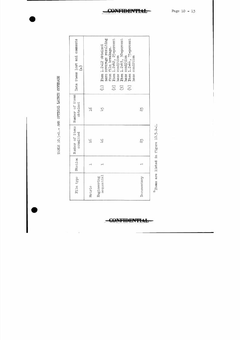
8/7/2019 Post Launch Memorandum Report for Mercury-Atlas No. 9(MA-9). Part 1 Mission Analysis
http://slidepdf.com/reader/full/post-launch-memorandum-report-for-mercury-atlas-no-9ma-9-part-1-mission 336/344
Page 10 - 13
w-p
Q J
0o
•d
CO
-pra ^-x0 cd
CO
iQ J-p•H
C O-p
COp
raSC D
-P•H TI^
C D
0 -HCO
rH ~P
CD rQ
£> O
ra
1
-P <d•H CD-P
'in -pO -H
orH g
C D O
GO•H-P
C O-Pto
CD
5j-P
JE;H„_!pr.
b O -P -P -PG G G G
•H Q J C D C D< d -P o o o
G 2 CD QJ QJ CD•H 03 bD ft ft ft
C T J QJ CO 1-P rH ! 1TN O TN
,Q C O O J G K A G I ^ - GO C D C D O O O
bO fn *> -H " -H "^ -HO J cd r C!OJ-P t^4
J-^ |- -P
H fn Jt -H -=h -H J- -Hi Q j 2 ' r d ' l d ' r d
O J i>rHOJ GOJ GOJ G. O -H • O • O • O
HO'i -l r- IOrHOrHO
g O g S C D g C D S C DC D r H O C D N C D t s l Q J I S I
- P C D r H - P C O - P C O - P C OHts|CHH^!H^!H^!
rH OJ K -=h
^
VD LTA
1 1 - t"
V O M DrH J-
K^CO
roC O
H rH rH
H
t j Q C OG -H•H -PrH G
C D C D0 QJ 3
•H G C^rH -H CD-p tiD raQ J GS W
&C O
-pGC DI
^jOOp
Iaj
ir\oH
ih
G
CO
-PM•H
H
W
§
C O N F I D E N T I A L
8/7/2019 Post Launch Memorandum Report for Mercury-Atlas No. 9(MA-9). Part 1 Mission Analysis
http://slidepdf.com/reader/full/post-launch-memorandum-report-for-mercury-atlas-no-9ma-9-part-1-mission 337/344
1 0 -
10.6 Postf light Inspection
Spacecraft 20, shown in figure 10.6-1, underwent the normal
postflight inspection and conditioning procedure. A thorough visual
inspection was made of the external and internal areas of the space-craft in the "as received" condition. The immediate postflight-
inspection procedure included removal of the heat shield, landingbag,
and conical and beryllium shingles for inspection of the pressure
bulkhead and internal skin areas. A photographic record was made of
the inspection process.
A desalting wash-down, tank drainage, and flushing procedure, as
applicable, was accomplished; and safeguards against deterioration
were taken. The detailed inspection results of the individual space-
craft structural systems are discussed in the following paragraphs.
10.6.1 General.- The overall condition of the spacecraft structurewas good. The outer pane of the spacecraft window was
broken during actuation of the explosive hatch aboard the
recovery ship. As on previous flights, there were drops
of water on the inside of the outer pane of the spacecraft
window. The exterior of the spacecraft showed the usual
discoloration due to aerodynamic heating. There were
numerous deposits of molten metal on both the conical and
cylindrical portions of the spacecraft exterior. The
deposits were in the areas above each of the three
retropackage umbilicals and one of the spacecraft-adapter
umbilicals, all of which failed to jettison from the
spacecraft. Most of the deposits had the appearance ofsolder spots. There was also evidence of considerable
aerodynamic heating in the area around where the still
attached umbilicals were located.
The coaxial antenna cable also did not separate from the
spacecraft, although it had been severed by the coaxial
cutter located beneath the shingle. The cable evidently
was caught at the hole in the shingle, through which it
passed and broke off,leaving about 6 inches of free cable
remaining.
Hydrogen peroxide was noted to be dripping very slowlyfrom the spacecraft between stringers 15 and l6 on to the
edge of the heat shield. Subsequent inspection showed that
an RCS line beside stringer 15 had corroded through from
the outside and was leaking hydrogen peroxide. Several
RCS lines had "considerable amounts of corrosion on their
outer surfaces; however, all RCS lines were exceptionally
clean and free of corrosion on their inner surfaces.
COMJD:
8/7/2019 Post Launch Memorandum Report for Mercury-Atlas No. 9(MA-9). Part 1 Mission Analysis
http://slidepdf.com/reader/full/post-launch-memorandum-report-for-mercury-atlas-no-9ma-9-part-1-mission 338/344
Page 10 - 15
10.6.2 Structure.- The spacecraft experienced very little
structural damage. Two cracks in the outer skin of the
pressure vessel, one of which was 3^ inches long and the
other 2 inches long, were noted in the area just to theright of the hatch. This damage most probably resulted
from the explosive-hatch actuation which produced a warpin the hatch sill.
10.6.3 Ablation shield.- The ablation shield appeared to be intact.
There were several minor circumferential cracks noted in
ablation laminate, but they were less severe than the ones
noted on the MA-8 heat shield. One of the heat-shield re-
taining lugs was broken off and another was bent. The
ablation-shield bondline under the flotation weights hadsep-
arated in places, but the bolts held the weights in place.
10.6.^4- Landing bag.-The landing bag was slit vertically in six
places. The slits varied in length from 6 to 20 inches.
In addition, there were numerous small tears and punctures
near the top of the bag. All of the landing bag straps
were intact, although they were twisted and kinked.
Twisting and kinking probably occurred during postrecovery
handling.
10.6.5 Recovery compartment.- Wo damage was noted in the recovery
compartment area except that the UHF descent and recovery
antenna was broken loose at the hinge point. This damage
occurred while the spacecraft was being lifted aboard the
recovery ship.
10.6.6 Main pressure bulkhead.- The main pressure bulkhead area
sustained very little damage on landing. The postflight
appearance of the honeycomb structure was not noticeably
changed from that before the flight. The fiberglass shield
had five scratches along the right X-axis and a dent in the
center stiffening ring in the same location. The protector
over the manual system selector valve was bent; and two dents,
or creases, in a bead in the skin next to the valve indicated
that the skin was pushed in during the landing. Also, there
was a surface crack in a spot weld in this area.
10.6.7 Spacecraft interior.- The interior of the spacecraft was
in good condition. The astronaut's couch had been
removed by the recovery forces for access to the area under
the couch and it had been replaced without being bolted
down. Approximately 0.28 pound of liquid was removed from
under the couch by the recovery personnel, and approximately
0.39 pound of liquid was removed from the same area during
8/7/2019 Post Launch Memorandum Report for Mercury-Atlas No. 9(MA-9). Part 1 Mission Analysis
http://slidepdf.com/reader/full/post-launch-memorandum-report-for-mercury-atlas-no-9ma-9-part-1-mission 339/344
Page 10 - 16
postflight inspection at Cape Canaveral. A chemical
analysis of this liquid to determine its source is in
process. There was a considerable amount of paint chips
throughout the interior of the spacecraft. These chips
resulted from initiating the explosive-actuated hatch.
CONFIDE1
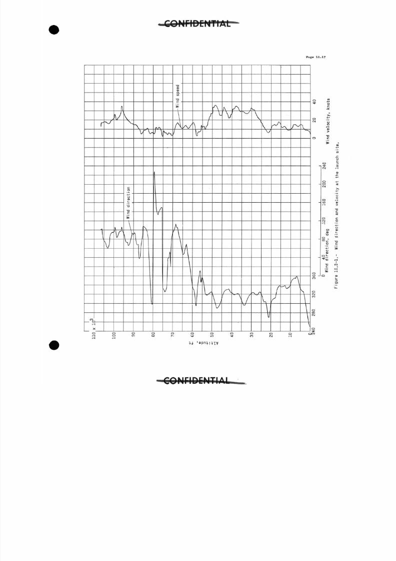
8/7/2019 Post Launch Memorandum Report for Mercury-Atlas No. 9(MA-9). Part 1 Mission Analysis
http://slidepdf.com/reader/full/post-launch-memorandum-report-for-mercury-atlas-no-9ma-9-part-1-mission 340/344
Page 10-17
A
.A/
V
V%
-
_
n
0(M
0>•D
D -
oCO
A I
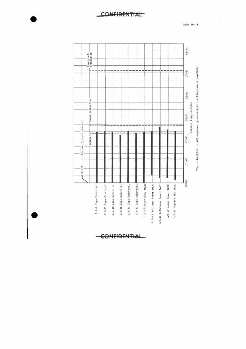
8/7/2019 Post Launch Memorandum Report for Mercury-Atlas No. 9(MA-9). Part 1 Mission Analysis
http://slidepdf.com/reader/full/post-launch-memorandum-report-for-mercury-atlas-no-9ma-9-part-1-mission 341/344
Page 10-18
< Hdb
BO
•H
O dO hO dd ftft 0)
m (0
5•Hd
0)
5 ^
inta
H
ft
o•H
%
s3-t
1C
I !e £
•HXd
f
ss
-q
>-
H
D1JH
J
._.
__
. ^>-
__
._ -
. _«.
_ _ _ _._M
H_- -
d d d r t d d O Q H Q Q
05:00
06:00
coverage.
9)
o
g |
00:00
01:00
02:00 03:00
04:
Elapsed time, rain: sec
Figure 10.5.2-1. - AMR engineering sequential track
U
CdO
CdU
BdO
CdO
BdO
ftdO O
OH
O Od dO O )
C O CO
&H-a!
rq
HCOT)<
rf
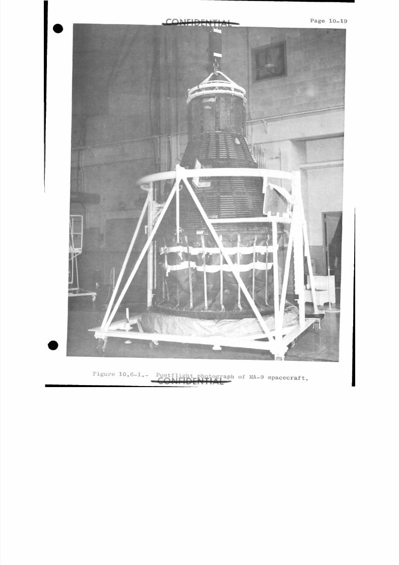
8/7/2019 Post Launch Memorandum Report for Mercury-Atlas No. 9(MA-9). Part 1 Mission Analysis
http://slidepdf.com/reader/full/post-launch-memorandum-report-for-mercury-atlas-no-9ma-9-part-1-mission 342/344
Page 10-
Figure 10.6-1.- o f M A~
9 s p a c e c r a f t-
8/7/2019 Post Launch Memorandum Report for Mercury-Atlas No. 9(MA-9). Part 1 Mission Analysis
http://slidepdf.com/reader/full/post-launch-memorandum-report-for-mercury-atlas-no-9ma-9-part-1-mission 343/344
Page 11-1
APPENDIX B
11.0 ACKNCMIiEDGEMENT
The Flight Evaluation Team for the MA-9flight, upon whose
analysis this report is "based, was composed as follows:
3.0 SPACE VEHICLE DESCRIPTION
3-1 Spacecraft Description
C. Vaughn
3.2 Launch Vehicle Description
L. DuGoffA. E. Franklin
14-.0 TRAJECTORY AND MISSION EVENTS
D. Incerto M. Apple
M. Cassetti F. McCreary
E. Hawkins J. Wells
P. McKaskill S. Yates
5.0 SPACECRAFT PERFORMANCE
5.1 'Spacecraft Control System
G. T. Sasseen
R. Buckley
T. Williams
5.2 Lift Support System
F. Samonski J. Billingham, M.D.
D. Hughes D. Hampton
J. Whalen F. Hettinger
5-3 Communications Systems
W. R. Stelges
5. Mechanical and Pyrotechnic Systems
S. T. Beddingfield
FIDENTIAL
8/7/2019 Post Launch Memorandum Report for Mercury-Atlas No. 9(MA-9). Part 1 Mission Analysis
http://slidepdf.com/reader/full/post-launch-memorandum-report-for-mercury-atlas-no-9ma-9-part-1-mission 344/344
11 - 2 COPTICC M T I A L i
5-5 Electrical and Sequential Systems
M. A. Guidry
J. D. Collner
5-6 Instrumentation System
¥. R. Durrett
M. A. Wedding
H. J. Ness
5-7 Heat Protection Systems
J. Pavlosky
5.8 Scientific Experiments
¥. ArmstrongJ. McKee
6.0 LAUNCH VEHICLE PERFORMANCE
L. DuGoff
M. Cassetti
A. E. Franklin
7.0 ASTRONAUT ACTIVITIES
7-1 Aeromedical Analysis
E. P. McCutcheon, M.D.D. D. Catterson, M.D.
R. A. Pollard, M.D.
H. A. Minners, M.D.
R. Hackworth
7-2 Astronaut Performance
J. B. Jones T. ¥. Holloway
J. J. Van Bockel R. B. Benson
R. D. Mercer G. ¥. Harvey
7.3 Pilot's Flight Report
L. G. Cooper, Jr.
8.0 FLIGHT CONTROL AND NETWORK PERFORMANCE
8.1 Flight Control Summary
C. Kraft
E. Kranz
J. Hodge