Embed Size (px)
Citation preview
Position control of a ferromagnetic micro-particle in a dry environment
Soukeyna Bouchebout1, Aude Bolopion2, Michael Gautier2 and Stephane Regnier1
Abstract— Most of current wireless micro-robotic systemsevolve in liquids, as the predominance, at this scale, of sur-face adhesion makes it hard to control these systems in dryenvironments. The purpose of this article is to propose amethod to improve wireless micro-devices performances in theair, by focusing on the workspace substrate. In this work, amagnetically actuated micro-particle is described and a strategyto limit the surface forces is presented. The micro-devicebehavior is studied and compared on five different surfaces.We demonstrate that reducing the electrical resistivity and theroughness of the surface helps improving the particle actuationoccurrence. Furthermore, to validate the proposed approach,the particle is positioned with high precision using a closed loopcontrol based on visual feedback. The micro-particle responseis identified using a statistical approach over a large micro-particle response database.
I. INTRODUCTION
The new field of untethered micro/nano sized devicespresents promising applications in several fields. For ex-ample, in biomedicine inside micro-fluidic chips [1], inmedicine for mini invasive surgery devices [2] and targeteddrug delivery, as well as in advanced manufacturing toassemble micro-components [3] or to perform mechanicalcharacterization [4]. Untethered micro-devices benefit fromtheir small size to fit in clustered environment and performtasks on micro-objects. The low inertia of these devicesallows high velocities, hence they can carry out many actionsin a short time.
However, the reduced size of the untethered submillimeterdevices makes it currently impracticable to be embeddedwith energy sources or sensors. Off-board power methods canbe used at this scale. Major progresses have been achieved inthis area. Electrostatic effect [5] is used to wirelessly powerscratch drive devices. However, this method requires specificsurfaces to operate on. Otherwise, the dielectrophoresis actu-ation [6] uses the dielectric forces to create motion but needsa high voltage. Moreover, electromagnetism is widely usedas an external energy source. For instance, the Magneticallydriven MicroTool (MMT) [1] [7] uses permanent magnetsas a power source and presents good results in manipulat-ing biological cells inside microfluidic channels. Swimming
*This work has been supported by the Labex ACTION project (con-tract ”ANR-11-LABX-01-01”), the French RENATECH network and itsFEMTO-ST technological facility and the French Agence Nationale de laRecherche, through the LEMA project (contract ANR 12 BS03 007 01)
1S. Bouchebout · S. Regnier are with the Institut des SystemeIntelligents et de Robotique (ISIR), Universite Pierre et MarieCurie/CNRS UMR-7222, BC 173, 4 Place Jussieu, 75005 Paris, Francebouchebout,[email protected]
2A. Bolopion · M. Gautier are with the FEMTO-ST Institute, UFC,ENSMM, UTBM, CNRS UMR-6174, 24 rue Alain Savary, 25000 Besancon,France [email protected]
micro-robots [8] [9] [10] operate using magnetic actuationas a remote propulsion in a liquid environment, hence theyare well suited for in vivo and in vitro applications. Besides,other mobile micro-devices employ electromagnets for actua-tion [11][12][13]. Therefore, the magnetic field is well suitedto remotely actuate micro-devices. Furthermore, to performmicro-assembly or micro-manipulation tasks, the control ofthe untethered devices is required at high speed and highprecision. A closed/open loop control is based on a posi-tion/velocity/acceleration feedback. However, at this scale,embedding accelerometers or sensors is hard to achieve. Toovercome this issue, image based detection using cameras[12] is widely used; as it offers, though with a limiteddetection field, a high speed tracking at low cost. Otherlocalization methods can be employed like fluoroscopy, MRI(magnetic resonance imaging) [14] [15], etc.
In addition, at the micro-scale, adhesion effects due to cap-illary, electrostatic, van der Waals, etc., dominate the physics[16][17] in liquids and, in particular, dry environments.Most magnetic based systems [11][18] evolve in a liquidenvironment. However, in a liquid, the micro-devices velocityis reduced due to the drag force which is proportional tothe device speed [19]. In contrast, micro-robotic systemsoperating in the air benefit from high dynamics but sufferfrom frequent adhesions to the surface. To avoid this issue,wireless micro-devices use, beside the magnetic actuation,the electrostatic effect [20]: the interdigitaded electrodesin an engineered surface induce a charge separation inthe micro-device metallic part and therefore regulate thefrictional forces. Also, the piezoelectric properties [21] canbe employed to engender vibrations to a micro-particle bya successive distortion of the sample, thus limiting theadhesion to surface. Although, these methods require highvoltages and specific surfaces that increase the productioncosts. Another solution to reduce the surface adhesion is tofocus on the workspace substrate. A particular material andtexture of the surface are used in [22] to perform the graspingof micro-spheres in a dry environment. The limitation of thesurface adhesion is important to obtain a reliable, fast andprecise control of magnetic actuated micro-devices in the air.
This article focuses on the untethered magnetically ac-tuated micro-tool, evolving in the air. Currently, the re-peatability of the micro-particle displacement in the air isinsufficient for reliable control. The challenge in actuatingand controlling micro-devices in a dry environment is toreduce the surface adhesion. The approach in this articlerelies on the substrate engineering. Using micro-fabricationprocesses, the surface roughness is controlled, and the effectof the substrate material and surface finish on the particle
adhesion to the substrate is addressed. We demonstrate thatthe electrical properties and the substrate finish are importantand enhances the particle performances in the air, beside,it enables controlling the system at high precision usinga simple closed loop control. The control of the particleposition is a vision based closed-loop, synthesized upon theparticle response characterization using a statistical approachover a large experimental database.
The magnetic actuation in dry environments and its mainchallenges are presented in the second section. A solutionto address the adhesion issue is proposed in the third sec-tion. The control of a magnetic actuation based system isapproached in the fourth section. The final section concludesand provides directions for future works.
II. THE UNTETHERED MICRO-ROBOTIC SYSTEM
’Untethered’ means for a micro-robotic system that itsmicro-end effector is wirelessly manipulating objects andevolving in the environment. In this work, vision baseddetection methods are used to locate the manipulator and themagnetic field is employed to actuate the end effector (alsocalled micro-particle). The micro-robotic system is describedin this section.
A. Particle micro-fabrication
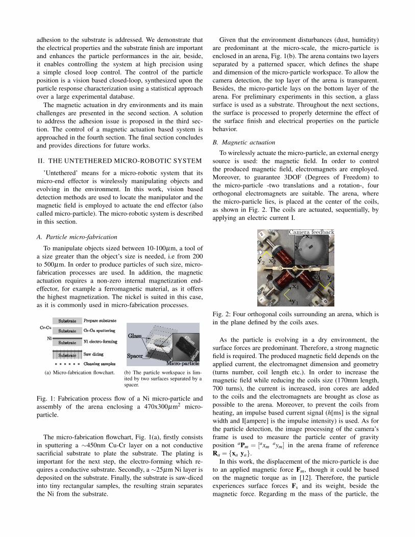
To manipulate objects sized between 10-100µm, a tool ofa size greater than the object’s size is needed, i.e from 200to 500µm. In order to produce particles of such size, micro-fabrication processes are used. In addition, the magneticactuation requires a non-zero internal magnetization end-effector, for example a ferromagnetic material, as it offersthe highest magnetization. The nickel is suited in this case,as it is commonly used in micro-fabrication processes.
(a) Micro-fabrication flowchart. (b) The particle workspace is lim-ited by two surfaces separated by aspacer.
Fig. 1: Fabrication process flow of a Ni micro-particle andassembly of the arena enclosing a 470x300µm2 micro-particle.
The micro-fabrication flowchart, Fig. 1(a), firstly consistsin sputtering a ∼450nm Cu-Cr layer on a not conductivesacrificial substrate to plate the substrate. The plating isimportant for the next step, the electro-forming which re-quires a conductive substrate. Secondly, a ∼25µm Ni layer isdeposited on the substrate. Finally, the substrate is saw-dicedinto tiny rectangular samples, the resulting strain separatesthe Ni from the substrate.
Given that the environment disturbances (dust, humidity)are predominant at the micro-scale, the micro-particle isenclosed in an arena, Fig. 1(b). The arena contains two layersseparated by a patterned spacer, which defines the shapeand dimension of the micro-particle workspace. To allow thecamera detection, the top layer of the arena is transparent.Besides, the micro-particle lays on the bottom layer of thearena. For preliminary experiments in this section, a glasssurface is used as a substrate. Throughout the next sections,the surface is processed to properly determine the effect ofthe surface finish and electrical properties on the particlebehavior.
B. Magnetic actuation
To wirelessly actuate the micro-particle, an external energysource is used: the magnetic field. In order to controlthe produced magnetic field, electromagnets are employed.Moreover, to guarantee 3DOF (Degrees of Freedom) tothe micro-particle -two translations and a rotation-, fourorthogonal electromagnets are suitable. The arena, wherethe micro-particle lies, is placed at the center of the coils,as shown in Fig. 2. The coils are actuated, sequentially, byapplying an electric current I.
Fig. 2: Four orthogonal coils surrounding an arena, which isin the plane defined by the coils axes.
As the particle is evolving in a dry environment, thesurface forces are predominant. Therefore, a strong magneticfield is required. The produced magnetic field depends on theapplied current, the electromagnet dimension and geometry(turns number, coil length etc.). In order to increase themagnetic field while reducing the coils size (170mm length,700 turns), the current is increased, iron cores are addedto the coils and the electromagnets are brought as close aspossible to the arena. Moreover, to prevent the coils fromheating, an impulse based current signal (h[ms] is the signalwidth and I[ampere] is the impulse intensity) is used. As forthe particle detection, the image processing of the camera’sframe is used to measure the particle center of gravityposition aPm = [axm
aym] in the arena frame of referenceRa = {xa ya}.
In this work, the displacement of the micro-particle is dueto an applied magnetic force Fm, though it could be basedon the magnetic torque as in [12]. Therefore, the particleexperiences surface forces Fs and its weight, beside themagnetic force. Regarding m the mass of the particle, the
equation of motion is as follow:
Fs +Fm +mg = maPm
where aPm and g are respectively the acceleration and thegravity. The magnetic force depends on the magnetic fieldgradient:
Fm = V(M ·∇)B
considering that the particle is of a volume V and is madeof a ferromagnetic material with a magnetization M. As theparticle is assumed saturated, the particle magnetization Mis constant. Hence, the magnetic force is proportional to theapplied magnetic field gradient.
The magnetic field, thus the magnetic field gradient,depends on the relative particle position to the electromagnetand the current I applied to this coil. To determine theparticle position according to a coili, iPm = [ixm
iym], a twisttransformation matrix aTi is used. In this work, the magneticfield is considered predominant in the coil axis and directedtoward it, as the electromagnets are four times the size ofthe arena and are arranged in a configuration close to theworkspace. The magnetic field is then assumed to be varyingonly in the coil axis, and can be expressed by:
||B||= fB(I, ixm)
and by differentiating the magnetic field gradient magnitudeis expressed by:
||∇B||= f∇B(I, ixm)
The relationship between the generated magnetic field andthe applied current and distance to the coil is interpolatedfrom experimental measurements.
Fig. 3: To apply a given ||∇B||re f during a time h, therequired current I is computed according to the currentparticle position to the actuated coili.
In addition, the magnetic force depends on the particleposition and the applied current. For a desired displacement,the applied force should be constant regardless of the par-ticle position. As shown in Fig. 3, the system inputs are||∇B||[mT/mm] and h[ms], and produce the movement ofthe particle at the new position aPm.
C. Actuation results
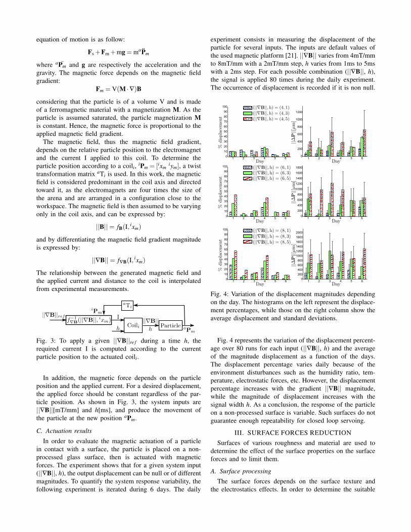
In order to evaluate the magnetic actuation of a particlein contact with a surface, the particle is placed on a non-processed glass surface, then is actuated with magneticforces. The experiment shows that for a given system input(||∇B||, h), the output displacement can be null or of differentmagnitudes. To quantify the system response variability, thefollowing experiment is iterated during 6 days. The daily
experiment consists in measuring the displacement of theparticle for several inputs. The inputs are default values ofthe used magnetic platform [21]. ||∇B|| varies from 4mT/mmto 8mT/mm with a 2mT/mm step, h varies from 1ms to 5mswith a 2ms step. For each possible combination (||∇B||, h),the signal is applied 80 times during the daily experiment.The occurrence of displacement is recorded if it is non null.
1 2 3 4 5 60
200
400
600
800
1000
1200
1400
1600
1800
2000
1 2 3 4 5 60
10
20
30
40
50
60
70
80
90
100
1 2 3 4 5 60
200
400
600
800
1000
1200
1400
1600
1800
1 2 3 4 5 6
1 2 3 4 5 60
200
400
600
800
1000
1200
1 2 3 4 5 60
10
20
30
40
50
60
70
80
90
100
Fig. 4: Variation of the displacement magnitudes dependingon the day. The histograms on the left represent the displace-ment percentages, while those on the right column show theaverage displacement and standard deviations.
Fig. 4 represents the variation of the displacement percent-age over 80 runs for each input (||∇B||, h) and the averageof the magnitude displacement as a function of the days.The displacement percentage varies daily because of theenvironment disturbances such as the humidity ratio, tem-perature, electrostatic forces, etc. However, the displacementpercentage increases with the gradient ||∇B|| magnitude,while the magnitude of displacement increases with thesignal width h. As a conclusion, the response of the particleon a non-processed surface is variable. Such surfaces do notguarantee enough repeatability for closed loop servoing.
III. SURFACE FORCES REDUCTION
Surfaces of various roughness and material are used todetermine the effect of the surface properties on the surfaceforces and to limit them.
A. Surface processing
The surface forces depends on the surface texture andthe electrostatics effects. In order to determine the suitable
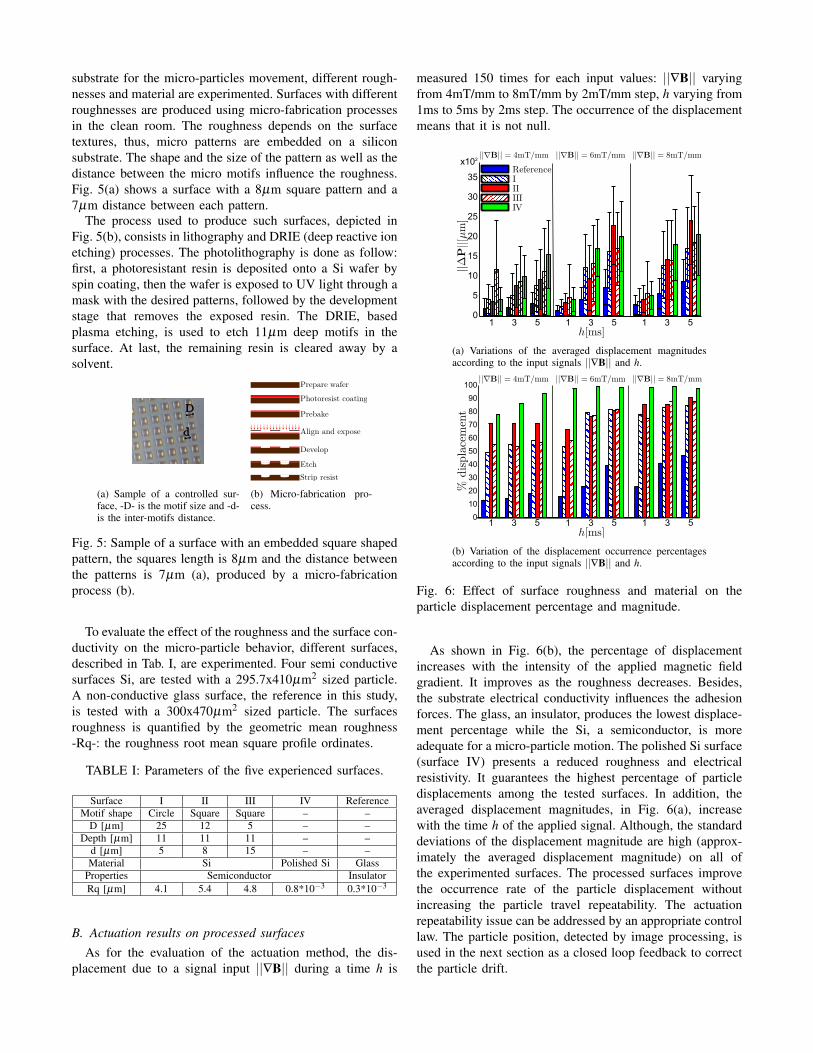
substrate for the micro-particles movement, different rough-nesses and material are experimented. Surfaces with differentroughnesses are produced using micro-fabrication processesin the clean room. The roughness depends on the surfacetextures, thus, micro patterns are embedded on a siliconsubstrate. The shape and the size of the pattern as well as thedistance between the micro motifs influence the roughness.Fig. 5(a) shows a surface with a 8µm square pattern and a7µm distance between each pattern.
The process used to produce such surfaces, depicted inFig. 5(b), consists in lithography and DRIE (deep reactive ionetching) processes. The photolithography is done as follow:first, a photoresistant resin is deposited onto a Si wafer byspin coating, then the wafer is exposed to UV light through amask with the desired patterns, followed by the developmentstage that removes the exposed resin. The DRIE, basedplasma etching, is used to etch 11µm deep motifs in thesurface. At last, the remaining resin is cleared away by asolvent.
(a) Sample of a controlled sur-face, -D- is the motif size and -d-is the inter-motifs distance.
(b) Micro-fabrication pro-cess.
Fig. 5: Sample of a surface with an embedded square shapedpattern, the squares length is 8µm and the distance betweenthe patterns is 7µm (a), produced by a micro-fabricationprocess (b).
To evaluate the effect of the roughness and the surface con-ductivity on the micro-particle behavior, different surfaces,described in Tab. I, are experimented. Four semi conductivesurfaces Si, are tested with a 295.7x410µm2 sized particle.A non-conductive glass surface, the reference in this study,is tested with a 300x470µm2 sized particle. The surfacesroughness is quantified by the geometric mean roughness-Rq-: the roughness root mean square profile ordinates.
TABLE I: Parameters of the five experienced surfaces.
Surface I II III IV ReferenceMotif shape Circle Square Square – –
D [µm] 25 12 5 – –Depth [µm] 11 11 11 – –
d [µm] 5 8 15 – –Material Si Polished Si Glass
Properties Semiconductor InsulatorRq [µm] 4.1 5.4 4.8 0.8*10−3 0.3*10−3
B. Actuation results on processed surfacesAs for the evaluation of the actuation method, the dis-
placement due to a signal input ||∇B|| during a time h is
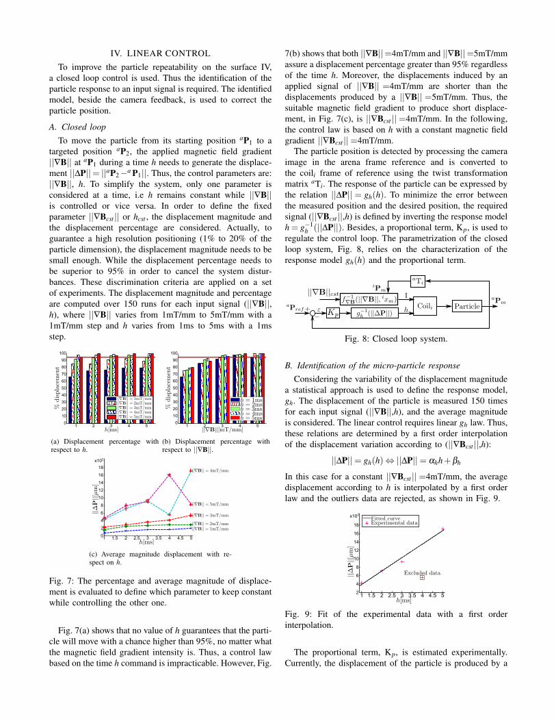
measured 150 times for each input values: ||∇B|| varyingfrom 4mT/mm to 8mT/mm by 2mT/mm step, h varying from1ms to 5ms by 2ms step. The occurrence of the displacementmeans that it is not null.
0
5
10
20
25
30
35
15
x102
1 3 5 1 3 5 1 3 5
(a) Variations of the averaged displacement magnitudesaccording to the input signals ||∇B|| and h.
1 3 5 1 3 5 1 3 50
10
20
30
40
50
60
70
80
90
100
(b) Variation of the displacement occurrence percentagesaccording to the input signals ||∇B|| and h.
Fig. 6: Effect of surface roughness and material on theparticle displacement percentage and magnitude.
As shown in Fig. 6(b), the percentage of displacementincreases with the intensity of the applied magnetic fieldgradient. It improves as the roughness decreases. Besides,the substrate electrical conductivity influences the adhesionforces. The glass, an insulator, produces the lowest displace-ment percentage while the Si, a semiconductor, is moreadequate for a micro-particle motion. The polished Si surface(surface IV) presents a reduced roughness and electricalresistivity. It guarantees the highest percentage of particledisplacements among the tested surfaces. In addition, theaveraged displacement magnitudes, in Fig. 6(a), increasewith the time h of the applied signal. Although, the standarddeviations of the displacement magnitude are high (approx-imately the averaged displacement magnitude) on all ofthe experimented surfaces. The processed surfaces improvethe occurrence rate of the particle displacement withoutincreasing the particle travel repeatability. The actuationrepeatability issue can be addressed by an appropriate controllaw. The particle position, detected by image processing, isused in the next section as a closed loop feedback to correctthe particle drift.
IV. LINEAR CONTROLTo improve the particle repeatability on the surface IV,
a closed loop control is used. Thus the identification of theparticle response to an input signal is required. The identifiedmodel, beside the camera feedback, is used to correct theparticle position.
A. Closed loop
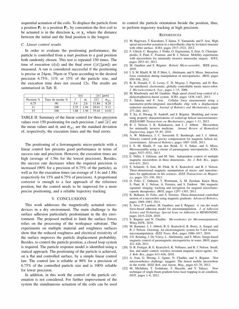
To move the particle from its starting position aP1 to atargeted position aP2, the applied magnetic field gradient||∇B|| at aP1 during a time h needs to generate the displace-ment ||∆P||= ||aP2−a P1||. Thus, the control parameters are:||∇B||, h. To simplify the system, only one parameter isconsidered at a time, i.e h remains constant while ||∇B||is controlled or vice versa. In order to define the fixedparameter ||∇Bcst || or hcst , the displacement magnitude andthe displacement percentage are considered. Actually, toguarantee a high resolution positioning (1% to 20% of theparticle dimension), the displacement magnitude needs to besmall enough. While the displacement percentage needs tobe superior to 95% in order to cancel the system distur-bances. These discrimination criteria are applied on a setof experiments. The displacement magnitude and percentageare computed over 150 runs for each input signal (||∇B||,h), where ||∇B|| varies from 1mT/mm to 5mT/mm with a1mT/mm step and h varies from 1ms to 5ms with a 1msstep.
1 2 3 4 50
10
20
30
40
50
60
70
80
90
100
(a) Displacement percentage withrespect to h.
0
10
20
30
40
50
60
70
80
90
100
1 2 3 4 5
(b) Displacement percentage withrespect to ||∇B||.
1 1.5 2 2.5 3 54 4.53.50
2
4
6
8
10
12
14
16
18
x102
(c) Average magnitude displacement with re-spect on h.
Fig. 7: The percentage and average magnitude of displace-ment is evaluated to define which parameter to keep constantwhile controlling the other one.
Fig. 7(a) shows that no value of h guarantees that the parti-cle will move with a chance higher than 95%, no matter whatthe magnetic field gradient intensity is. Thus, a control lawbased on the time h command is impracticable. However, Fig.
7(b) shows that both ||∇B||=4mT/mm and ||∇B||=5mT/mmassure a displacement percentage greater than 95% regardlessof the time h. Moreover, the displacements induced by anapplied signal of ||∇B|| =4mT/mm are shorter than thedisplacements produced by a ||∇B|| =5mT/mm. Thus, thesuitable magnetic field gradient to produce short displace-ment, in Fig. 7(c), is ||∇Bcst ||=4mT/mm. In the following,the control law is based on h with a constant magnetic fieldgradient ||∇Bcst ||=4mT/mm.
The particle position is detected by processing the cameraimage in the arena frame reference and is converted tothe coili frame of reference using the twist transformationmatrix aTi. The response of the particle can be expressed bythe relation ||∆P|| = gh(h). To minimize the error betweenthe measured position and the desired position, the requiredsignal (||∇Bcst ||,h) is defined by inverting the response modelh = g−1
h (||∆P||). Besides, a proportional term, Kp, is used toregulate the control loop. The parametrization of the closedloop system, Fig. 8, relies on the characterization of theresponse model gh(h) and the proportional term.
Fig. 8: Closed loop system.
B. Identification of the micro-particle responseConsidering the variability of the displacement magnitude
a statistical approach is used to define the response model,gh. The displacement of the particle is measured 150 timesfor each input signal (||∇B||,h), and the average magnitudeis considered. The linear control requires linear gh law. Thus,these relations are determined by a first order interpolationof the displacement variation according to (||∇Bcst ||,h):
||∆P||= gh(h)⇔ ||∆P||= αhh+βh
In this case for a constant ||∇Bcst ||=4mT/mm, the averagedisplacement according to h is interpolated by a first orderlaw and the outliers data are rejected, as shown in Fig. 9.
1 1.5 2 2.5 3 54 4.53.52
4
6
8
10
12
14
16
18
x102
Fig. 9: Fit of the experimental data with a first orderinterpolation.
The proportional term, Kp, is estimated experimentally.Currently, the displacement of the particle is produced by a
sequential actuation of the coils. To displace the particle froma position P1 to a position P2, by convention the first coil tobe actuated is in the direction xa or ya where the distancebetween the initial and the final position is the longest.
C. Linear control results
In order to evaluate the positioning performance, theparticle is controlled from a start position to a goal positionboth randomly chosen. This test is repeated 150 times. Thetime of execution (t[s]) and the final error (||ε||[µm]) aremeasured. A run is considered successful if the positioningis precise at 24µm, 39µm or 53µm according to the desiredprecision 6.75%, 11% or 15% of the particle size, andthe execution time does not exceed 12s. The results aresummarized in Tab. II.
t[s] ||ε|| [µm]Prcision % Taux de russite % t σt ||ε|| σ||ε||
6.75 90 3.4 2.6 11.84 8.2411 100 2.35 1.94 29.01 9.1115 100 1.88 1.56 35.44 14.01
TABLE II: Summary of the linear control for three precisionvalues over 150 positioning for each precision. t and ||ε|| arethe mean values and σt and σ||ε|| are the standard deviationof, respectively, the execution times and the final errors.
The positioning of a ferromagnetic micro-particle with alinear control law presents good performance in terms ofsuccess rate and precision. However, the execution times arehigh (average of 1.56s for the lowest precision). Besides,the success rate decreases when the required precision isincreased (90% for a precision of 6.75% of the particle), aswell as for the execution times (an average of 3.4s and 1.88srespectively for 15% and 6.75% of precision). A proportionalcorrector is enough to a fast approach of the referenceposition, but the control needs to be improved for a moreprecise positioning, and a reliable trajectory tracking.
V. CONCLUSIONS
This work addresses the magnetically actuated micro-devices in a dry environment. The main challenge is thesurface adhesion particularly predominant in the dry envi-ronment. The proposed method to limit the surface forcesrelies on the processing of the workspace substrate. Theexperiments on multiple material and roughness surfacesshow that the reduced roughness and electrical resistivity ofthe surface improves the particle displacement probability.Besides, to control the particle position, a closed loop systemis required. The particle response model is identified using astatical approach. The positioning of the particle is achieved,on a flat and controlled surface, by a simple linear controllaw. The control law is reliable at 90% for a precision of6.75% of the controlled particle size and is 100% reliablefor lower precision.
In addition, in this work the control of the particle ori-entation is not considered. For further improvement of thesystem the simultaneous actuation of the coils can be used
to control the particle orientation beside the position, thus,to perform trajectory tracking at high precision.
REFERENCES
[1] M. Hagiwara, T. Kawahara, T. Iijima, Y. Yamanishi, and F. Arai. Highspeed microrobot actuation in a microfluidic chip by levitated structurewith riblet surface. ICRA, pages 2517–2522, 2012.
[2] F. Ullrich, C. Bergeles, J. Pokki, O. Ergeneman, S. Erni, G. Chatzipir-piridis, S. Pane, C. Framme, and B. J. Nelson. Mobility experimentswith microrobots for minimally invasive intraocular surgery. IOVS,pages 2853–63, 2013.
[3] M. Gauthier and S. Regnier. Robotic Micro-assembly. IEEE press,2010.
[4] I. S. M. Khalil, R. M. P. Metz, L. Abelmann, and S. Misra. Interactionforce estimation during manipulation of microparticles. IROS, pages950–956, 2012.
[5] B. R. Donald, C. G. Levey, C. D. Mcgray, I. Paprotny, and D. Rus.An untethered, electrostatic, globally controllable mems micro-robot.J. Microelectromech. Syst., pages 1–15, 2006.
[6] M. Kharboutly and M. Gauthier. High speed closed loop control of adielectrophoresis-based system. ICRA, pages 1438–1443, 2013.
[7] S. Sakuma and F. Arai. Cellular force measurement using ananometric-probe-integrated microfluidic chip with a displacementreduction mechanism. Journal of Robotics and Mechatronics, pages277–284, 2013.
[8] T. Xu, G. Hwang, N. Andreff, and S. Regnier. Modeling and swim-ming property characterizations of scaled-up helical microswimmers.IEEE/ASME Transactions on Mechatronics, pages 1–11, 2013.
[9] B. J. Nelson, I. K. Kaliakatsos, and J. J. Abbott. Microrobotsfor minimally invasive medicine. Annual Review of BiomedicalEngineering, pages 55–85, 2010.
[10] A. W. Mahoneya, J. C. Sarrazinb, E. Bambergb, and J. J. Abbott.Velocity control with gravity compensation for magnetic helical mi-croswimmers. Advanced Robotics, pages 1007–1028, 2011.
[11] I. S. M. Khalil, F. van den Brink, O. S. Sukas, and S. Misra.Microassembly using a cluster of paramagnetic microparticles. ICRA,pages 5527–5532, 2013.
[12] E. Diller, J. Giltinan, and M. Sitti. Independent control of multiplemagnetic microrobots in three dimensions. Int. J. Rob. Res., pages614–631, 2013.
[13] S. Schuerle, S. Erni, M. Flink, B. E. Kratochvil, and B. J. Nelson.Three-dimensional magnetic manipulation of micro- and nanostruc-tures for applications in life sciences. IEEE Transactions on Magnet-ics, pages 321–330, 2013.
[14] D. Folio, C. Dahmen, T. Wortmann, A. M. Zeeshan, Kaiyu Shou,S. Pane, B. J. Nelson, A. Ferreira, and S. Fatikow. Mri magneticsignature imaging, tracking and navigation for targeted micro/nano-capsule therapeutics. IROS, pages 1297–1303, 2011.
[15] K. Belharet, D. Folio, and A. Ferreira. Three-dimensional controlledmotion of a microrobot using magnetic gradients. Advanced Robotics,pages 1069–1083, 2011.
[16] S. Alvo, P. Lambert, M. Gauthier, and S. Regnier. A van der waalsforce-based adhesion model for micromanipulation. J. of AdhesionScience and Technology, Special Issue on Adhesion in MEMS/NEMS,pages 2415–2428, 2010.
[17] S. Regnier and N. Chaillet. Microrobotics for Micromanipulation.Wiley-ISTE, 2010.
[18] M. Kummer, J. J. Abbott, B. E. Kratochvil, R. Borer, A. Sengul, andB. J. Nelson. Octomag: An electromagnetic system for 5-dof wirelessmicromanipulation. IEEE Trans. Rob., pages 1006–1017, 2010.
[19] J.D. Keuning, J. De Vriesy, L. Abelmanny, and S. Misra. Image-basedmagnetic control of paramagnetic microparticles in water. IROS, pages421–426, 2011.
[20] D. R. Frutiger, B. E. Kratochvil, K. Vollmers, and B. J. Nelson. Small,fast, and under control: wireless resonant magnetic micro-agents. Int.J. Rob. Res., pages 613–636, 2010.
[21] A. Ivan, G. Hwang, J. Agnus, N. Chaillet, and S. Regnier. Nistmicrororobotics challenge. magpier: The fastest mobile microrobotsin the world. IEEE Rob. and Autom. Mag., pages 63–70, 2013.
[22] M. Michihata, T. Yoshikane, T. Hayashi, and Y. Takaya. Newtechnique of single-beam gradient-force laser trapping in air condition.ISOT, pages 1–6, 2012.