Embed Size (px)
Citation preview
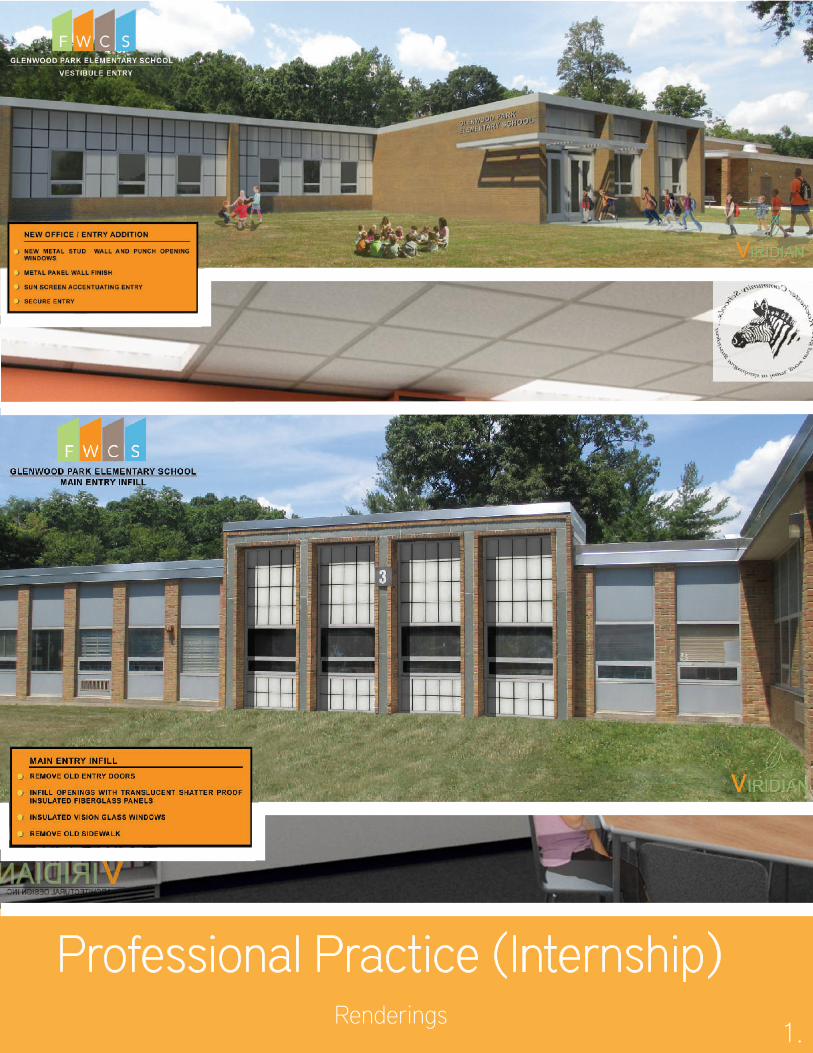
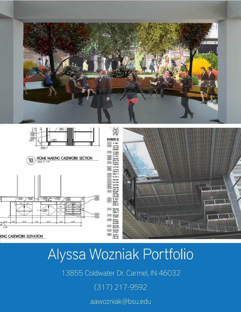
Professional Practice (Internship)Renderings
1.
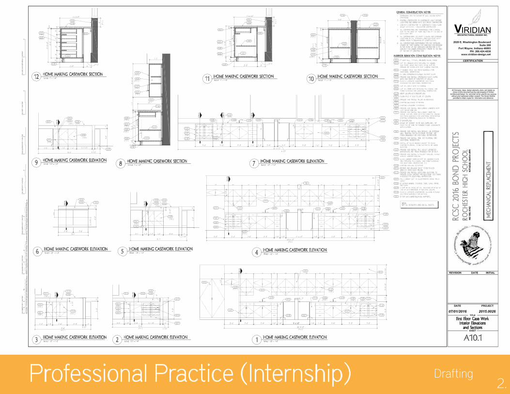
Professional Practice (Internship) Drafting2.
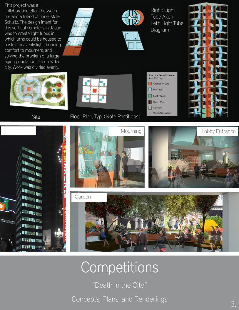
Competitions“Death in the City”
Concepts, Plans, and Renderings3.
Right: Light Tube AxonLeft: Light Tube Diagram
Site Floor Plan, Typ. (Note Partitions)
This project was a collaboration e�ort between me and a friend of mine, Molly Schultz. The design intent for this vertical cemetery in Japan was to create light tubes in which urns could be housed to bask in heavenly light, bringing comfort to mourners, and solving the problem of a large aging population in a crowded city. Work was divided evenly.
Night View Mourning Lobby Entrance
Garden
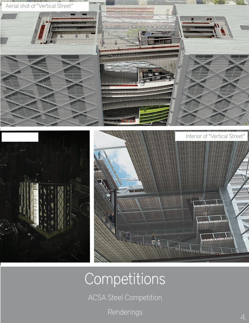
CompetitionsACSA Steel Competition
Renderings4.
Night View
Aerial shot of “Vertical Street”
Interior of “Vertical Street”
CompetitionsACSA Steel Competition
Program and Structure5.
STAY
‘VERTICAL STREETS’
WORK/PLAY
PROGRAM + CIRCULATION
FLOORS 1-4: MUSIC VENUES
FLOORS 5-8: LARGE PUBLIC VENUES
FLOORS 9-12: SMALL PUBLIC VENUES
FLOORS 13-16: LARGE PRIVATE VENUES
FLOORS 17-20: SMALL PRIVATE VENUES
FLOORS 21-24: BUSINESS VENUES
Vertical Circulation Cores
‘Street Vendor’ Spaces
Stairwells for short vertical circulation paths
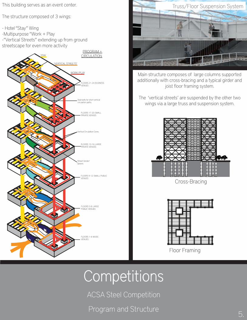
This building serves as an event center.
The structure composed of 3 wings:
- Hotel “Stay” Wing-Multipurpose “Work + Play-”Vertical Streets” extending up from ground streetscape for even more activity
Main structure composes of large columns supported additionally with cross-bracing and a typical girder and
joist floor framing system.
The ‘vertical streets’ are suspended by the other two wings via a large truss and suspension system.
Truss/Floor Suspension System
Cross-Bracing
Floor Framing
CompetitionsCRIPE Tiny Home Competition
Renderings and Site Plan6.
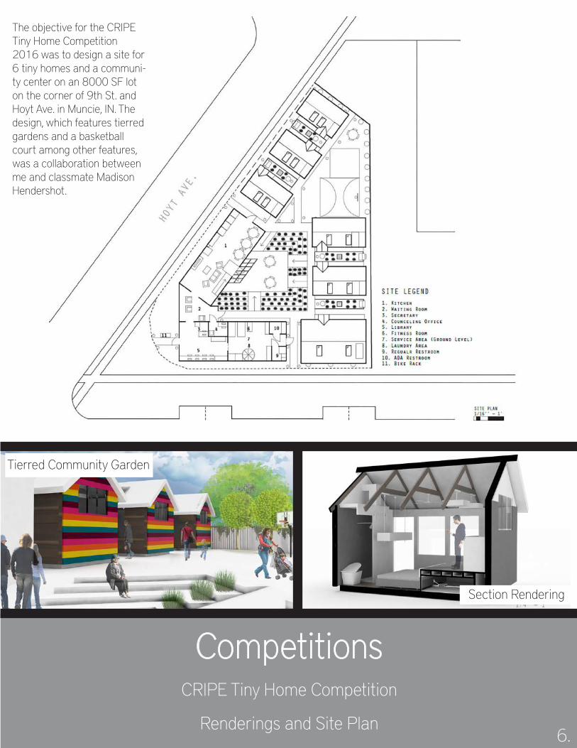
The objective for the CRIPE Tiny Home Competition 2016 was to design a site for 6 tiny homes and a communi-ty center on an 8000 SF lot on the corner of 9th St. and Hoyt Ave. in Muncie, IN. The design, which features tierred gardens and a basketball court among other features, was a collaboration between me and classmate Madison Hendershot.
Tierred Community Garden
Section Rendering
CompetitionsCRIPE Tiny Home Competition
Energy and Mechanics6.
Gypsum Board 1/2’’
SIPS OSB 1/2’’
SIPS Insul. 5-1/2’’ R-23
SIPS OSB 1/2’’
Vapor Membrane
Wood Siding 1/2’’
Furring Strips2’ O.C.
Wood Blocking
Woood Flooring 1/2’’
2x4
ScrewNeoprene 1/4’’
Treated Wood Blocking
10’’ Anchor Bolt
Screw
Gravel 6’’
Radiant Floor Syst.
4’’ Conc. Slab
Drainage Pipe
3x2 Conc. Footing
#4 Rebar
2’’ Rigid Insul R-10
X4 Rebar
1/4 Neoprene
Window Sash
Muntin
Vapor Membrane
Filler
Fascia
Sealant
12’’ Screw
SIPS OSB 1/2’’SIPS Insul. 5-1/2’’ R-29
SIPS OSB 1/2’’Roof Paper
Shingles
2’’ Rigid Insul R-10
Window Trim
Sealant
Wood Blocking
Drip Edge
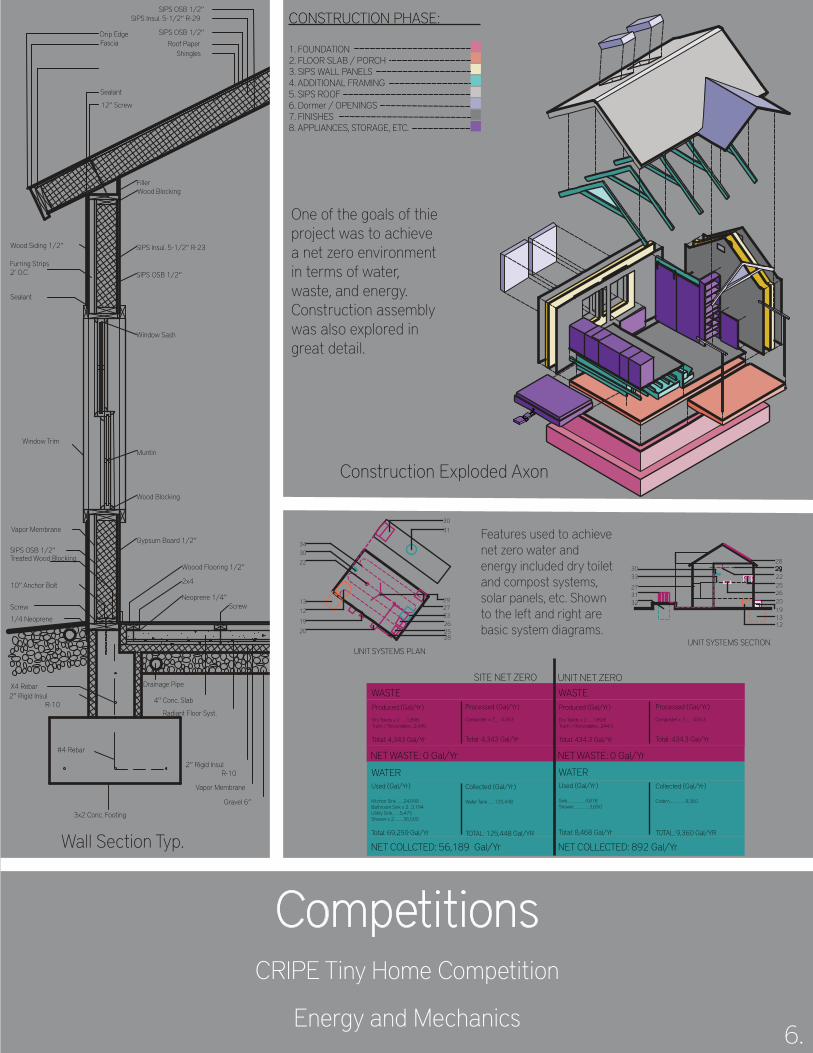
CONSTRUCTION PHASE:
1. FOUNDATION2. FLOOR SLAB / PORCH3. SIPS WALL PANELS4. ADDITIONAL FRAMING5. SIPS ROOF6. Dormer / OPENINGS7. FINISHES8. APPLIANCES, STORAGE, ETC.
WASTEProduced (Gal/Yr)
Dry Toilets x 2 ......1,898Trash / Recyclables...2,445
Total: 4,343 Gal/Yr
Processed (Gal/Yr)
Composter x 2.......4,343
Total: 4,343 Gal/Yr
NET WASTE: 0 Gal/Yr
WATERUsed (Gal/Yr)
Kitchen Sink........24,090Bathroom Sink x 2...3,194Utility Sink........5,475Shower x 2..........36,500
Total: 69,259 Gal/Yr
Collected (Gal/Yr)
Water Tank........125,448
TOTAL: 125,448 Gal/YR
NET COLLCTED: 56,189 Gal/Yr
WASTEProduced (Gal/Yr)
Dry Toilets x 2 ......189.8Trash / Recyclables...244.5
Total: 434.3 Gal/Yr
Processed (Gal/Yr)
Composter x 2.........434.3
Total: 434.3 Gal/Yr
NET WASTE: 0 Gal/Yr
WATERUsed (Gal/Yr)
Sink...................4,818Shower.................3,650
Total: 8,468 Gal/Yr
Collected (Gal/Yr)
Cistern.................9,360
TOTAL: 9,360 Gal/YR
NET COLLECTED: 892 Gal/Yr
SITE NET ZERO UNIT NET ZERO
UNIT SYSTEMS PLAN
2019
1213
28
3022
3031
27
25
3326
29
UNIT SYSTEMS SECTION
1319202625222928
3231
3330
34
12
27
One of the goals of thie project was to achieve a net zero environment in terms of water, waste, and energy. Construction assembly was also explored in great detail.
Section Rendering
Construction Exploded Axon
Wall Section Typ.
Features used to achieve net zero water and energy included dry toilet and compost systems, solar panels, etc. Shown to the left and right are basic system diagrams.
UP
School ProjectsBiophilic Design
Renderings and Program8.
BrooklynGovenor’s Island
Manhattan
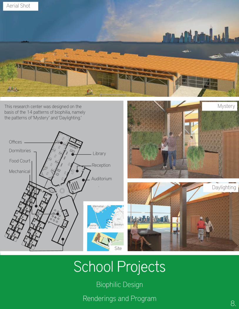
Aerial Shot
Mystery
Daylighting
This research center was designed on the basis of the 14 patterns of biophilia, namely the patterns of ‘Mystery’ and ‘Daylighting.’
Auditorium
Reception
Library
O�ces
Dormitories
Food Court
Mechanical
Site
School ProjectsBiophilic Design
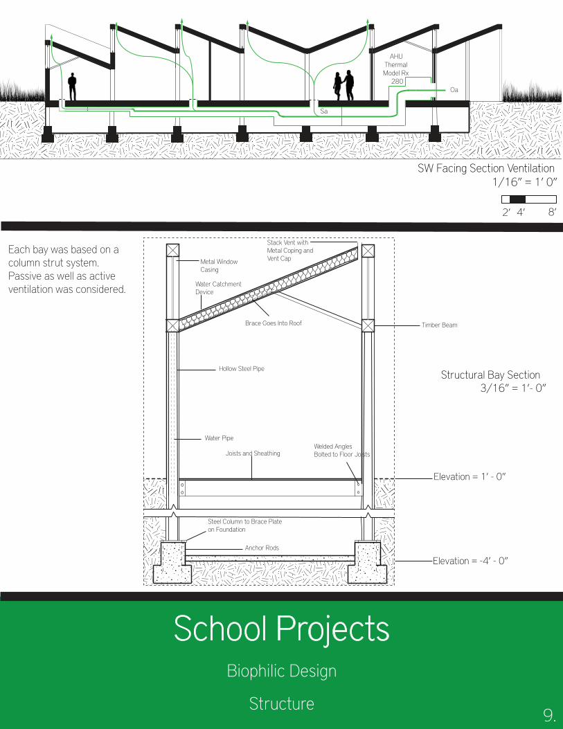
Structure9.
2’ 4’ 8’
SW Facing Section Ventilation 1/16’’ = 1’ 0’’
AHUThermal Model Rx
280Oa
Sa
Stack Vent with Metal Coping and Vent CapMetal Window
Casing
Water Catchment Device
Brace Goes Into Roof
Hollow Steel Pipe
Timber Beam
Water Pipe
Joists and SheathingWelded Angles Bolted to Floor Joists
Steel Column to Brace Plate on Foundation
Anchor Rods
Structural Bay Section3/16’’ = 1’- 0’’
Elevation = 1’ - 0’’
Elevation = -4’ - 0’’
Each bay was based on a column strut system. Passive as well as active ventilation was considered.
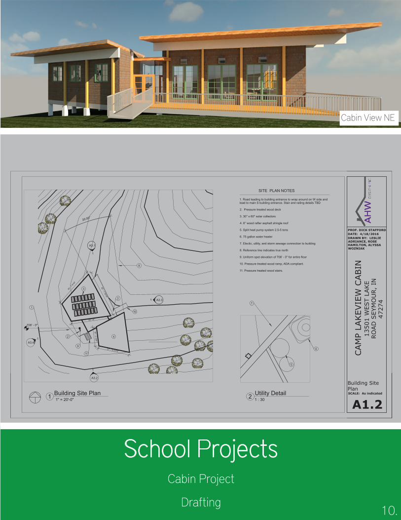
School ProjectsCabin Project
Drafting10.
A3.2
1
A3.1
1
A3.31
A3.41
27' - 10 3/16"
16' - 11 5/8"
35' -
7 5/16
"
42' - 1 15/16"
35' - 6"
20.00°
706' - 0"
PROF. DICK STAFFORD
SCALE: As indicated
A1.2
DATE: 4/18/2016
Building SitePlan
DRAWN BY: LESLIEADRIANCE, ROSEHAMILTON, ALYSSAWOZNIAK
CAM
P LA
KEV
IEW
CABIN
1350
1 W
EST
LAKE
RO
AD
SEY
MO
UR,
IN47
274
1" = 20'-0"1 Building Site Plan
1
2
SITE PLAN NOTES
1. Road leading to building entrance to wrap around on W side and lead to main S building entrance. Stair and railing details TBD
2. Pressure treated wood deck
3. 30'' x 60'' solar collectors
4. 6'' wood rafter asphalt shingle roof
5. Split heat pump system 2.5-5 tons
6. 75 gallon water heater
7. Electic, utility, and storm sewage connection to building
8. Reference line indicates true north
9. Uniform spot elevation of 706' - 0'' for entire floor
10. Pressure treated wood ramp, ADA compliant.
11. Pressure treated wood stairs.
2
3
4
1 : 302 Utility Detail
6
5
7
8
9
10
11
Cabin View NE
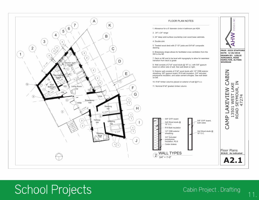
School Projects Cabin Project . Drafting11.
5/8" GYP. board, both sides
2x4 Wood studs @ 16" O.C.
5/8" GYP. board
2x6 Wood studs @ 16" O.C.
1/2" OSB exterior sheathing
3/4" Extruded polystyrene insulation, R3.8Cedar shakes
R19 Batt insulation
FD
TV
UP
12
3
5
A
F
B
C
D
E
4
67
G
H
I
J
101
Kitchen andDining
102Living Room
103
MechanicalSpace
104
ADABathroom
8' - 1
1/8"
8' - 5
1/2"
11 1/
8"
2' - 0
"
3' - 6 3/16"
4' - 5 13/16"
16' - 8 5/16"
9' - 8 3/4"
9' - 1 5/16"
5' - 10 5/8"
10' - 2 7/8"
26' - 0 1/4"
103
104
105B
105A
2
2
2
2
2
1 1
1
1
1
1
1
1
2
2
3
3
3
3
105Breezeway
106Hallway
107Sleeping
108Sleeping
109
ReadingNook
5
6
1
3
2
4
8
7
9
10
K
PROF. DICK STAFFORD
SCALE: As indicated
A2.1
DATE: 4/18/2016
Floor Plans
DRAWN BY: LESLIEADRIANCE, ROSEHAMILTON, ALYSSAWOZNIAK
CAM
P LA
KEV
IEW
CABIN
1350
1 W
EST
LAKE
RO
AD
SEY
MO
UR,
IN47
274
3/4" = 1'-0"WALL TYPES
FLOOR PLAN NOTES
1. Allowance for a 5' diameter circle in bathroom per ADA
2. 24'' x 24'' range
3. 24'' deep solid surface countertop over wood base cabimets.
4. Double sink
5. Treated wood deck with 2"-10'' joists and 5/4''x6" composite decking.
6. Breezeway shape allows for facilitated cross ventilation from the SW to the NE
7. Deck on NE end to be level with topography to allow for seamless transition from deck to grade
8. Wall consists of 2"x4" wood studs @ 16'' o.c. with 5/8'' gypsum board on either side of wall. See wall detail on right.
9. Exterior wall consists of 2"x6" wood studs with 1/2'' OSB exterior sheathing, 5/8'' gypsum board, R19 batt insulation, 2/4'' extruded polystyrene insulation, and cedar cement shingles. See wall detail on left.
10. 6"x6" timber columns placed on exterior of wall @ 8' o.c.
11. Nominal 6"x6" gluelam timber column.
2