Embed Size (px)
Citation preview
Transportation Research Record 1060
REFERENCES
1. Castle Rock Consultants. Heavy Vehicle Electronic License Plate System--Feasibility Study Report. Arizona Department of Transportation, Phoenix, Jan. 1985.
2. Marketing/Distribution Plan for Lo-Jack Corporation. Touche Ross and Company, Boston, Mass. (undated).
3. G. O'Neill. Geostar Location and Conununication System. Proc., NAV 1 84 Conference, Royal Institute of Navigation, London, England, 1984.
4. P. Davies and F.K. Sonunerville. Low-Cost WIM: The Way Forward. Proc., 2nd National Weigh-inMotion Conference, Atlanta, Ga., May 1985.
127
5. D.R. Salter and P. Davies. Development and Testing of a Portable Microprocessor-Based Capacitive Weigh-in-Motion System. In Transportation Research Record 997, TRB, National Research Council, Washington, D.C., 1984, pp. 61-69.
6. CRC Corporation. Heavy Vehicle Electronic License Plate System--Concept Development Study Report. Arizona Department of Transportation, Phoenix, June 1985.
Publication of this paper sponsored by Task Force on Weigh-in-Motion.
Portable Sensors and Equipment for
Traffic Data Collection
WILEY D. CUNAGIN, ALBERT B. GRUBBS, Jr., and
NADER A. AYOUB
ABSTRACT
In recent.years, the need for traffic data has increased although the resources available to collect them have decreased; consequently, the use of automated traffic data collection procedures and equipment has spread rapidly. These techniques and devices may be used in either a fixed or portable mode. Portable applications require the deployment of sensors that are accurate and rugged as well as portable, easily and quickly installed and .removed, and reusable. Presented in this paper are the results of an investigation into available technologies that may be used in portable sensors for vehicle detection. The emphasis of this research was on those technologies that may be used in temporary or short-term traffic data collection. A second objective of this study was to develop performance requirements for portable automated traffic data collection equipment. The research was funded by the Federal Highway Administration under a contract entitled "Automated Speed Data Collection for Temporary Applications."
As the need and demand for traffic data and monitoring have increased over the last few years, the available manpower and financial resources to provide this information have declined in many public agencies. Consequently, the use of automated traffic data collection procedures and equipment has rapidly increased. This technology includes devices that are portable as well as those that are permanently installed. The equipment in all cases includes a sensor that is placed on, in, or near the roadway and provides an indication of vehicle passage and pres-
Texas A&M University, College Station, Texas 77843.
ence, or both. (Weigh-in-motion devices were not included in this research.) The equipment also includes a detector that interprets a sensor actuation as information and processes or stores it in useful form. The balance of the data collection equipment system consists of computational, data storage, or conununication elements. This report deals with portable sensors and equipment used for temporary traffic data collection or monitoring.
Portable applications require the deployment of sensors that are both accurate and durable. Portable sensors fall into two general types--those that are fixed to the surface of the roadway (such as pneu-

128
matic tubes) and those that are placed at the side of (or above) the roadway (such as infrared sensors). Possible portable traffic sensor alternatives were assessed in this study with respect to their technical effectiveness, probability of user acceptance, and cost. The evaluation of technical effectiveness included accuracy, sensitivity, ability to reject spurious signals, environmental limitations, possible problems related to interfacing with traffic data collection equipment, and adaptability to a range of roadway geometric and surface textural conditions. User acceptance issues comprised portability, ease of installation and removal (including time and manpower requirements), hazard of installation, vulnerability to vandalism, operational life, and conspicuity. Cost includes original price, installation and removal, and maintenance. As a result of this evaluation, it was concluded that three technologies show the greatest promise for increased use in the future for temporary traffic data collection. They are (a) piezoelectric cable, (b) infrared detectors, and (c) laser beams. These an~ other concepts that may be or are useful for temporary traffic data collection are discussed in the following sections.
A second part of the research effort was directed toward what types and amounts of traffic data are commonly collected. Information was obtained from published literature as well as from practicing professionals and was used to determine performance requirements for portable sensors and data collection equipment. In addition, an advisory panel of city, county, and state traffic engineers from around the country was used to: review and comment on traffic sensor concepts; provide input on traffic data requirements; identify desirable properties of automated traffic data collection equipment and portable sensors; and determine the relative importance of factors to be considered in the evaluation of the equipment. The following sections discuss the details, results, and conclusions of the research.
PORTABLE TRAFFIC SENSOR TECHNOLOGIES
Current practice in portable traffic data collection is heavily dependent on two sensor types--pneumatic tubes for traffic volume counts and radar units for speed data. Pneumatic tube sensors are normally placed across a traffic lane perpendicular to the flow of traffic. As a tire passes over the pneumatic tube, the air within the tube is compressed, forcing a diaphragm connected to one end to allow a pulse of ~ir throu~h= This action is interpreted by aet~ctinn circuitry as a switch closure and the actuation is recorded by incrementinq a counter (for volume counting applications) or as an event time if the pneumatic tube is being used to acquire speed, vehicle type, vehicle separation, or truck weight data. Portable radar units generate a microwave beam that is directed at oncoming vehicles. The signal is reflected back to the unit and the resulting Doppler effect frequency shift is interpreted as a speed. These two sensor concepts have been widely used because they are well suited to portable and temporary applications. The advantages and disadvantages of these devices will be discussed in the following paragraphs and compared to other technologies that may be used for this purpose.
Surface-Mounted Portable Sensors
A wide variety of surface-mounted portable traffic sensors have been used to some degree. These include pneumatic tubes, tapeswitches, piezoelectric and
Transportation Research Record 1060
tr iboelectr ic cables, and specially constructed inductive loops. Some technologies that have not been widely used in portable devices, but that may show some promise in the future, are seismic, piezoelectric film, capacitive strip, and magnetic sensors.
Pneumatic Tubes
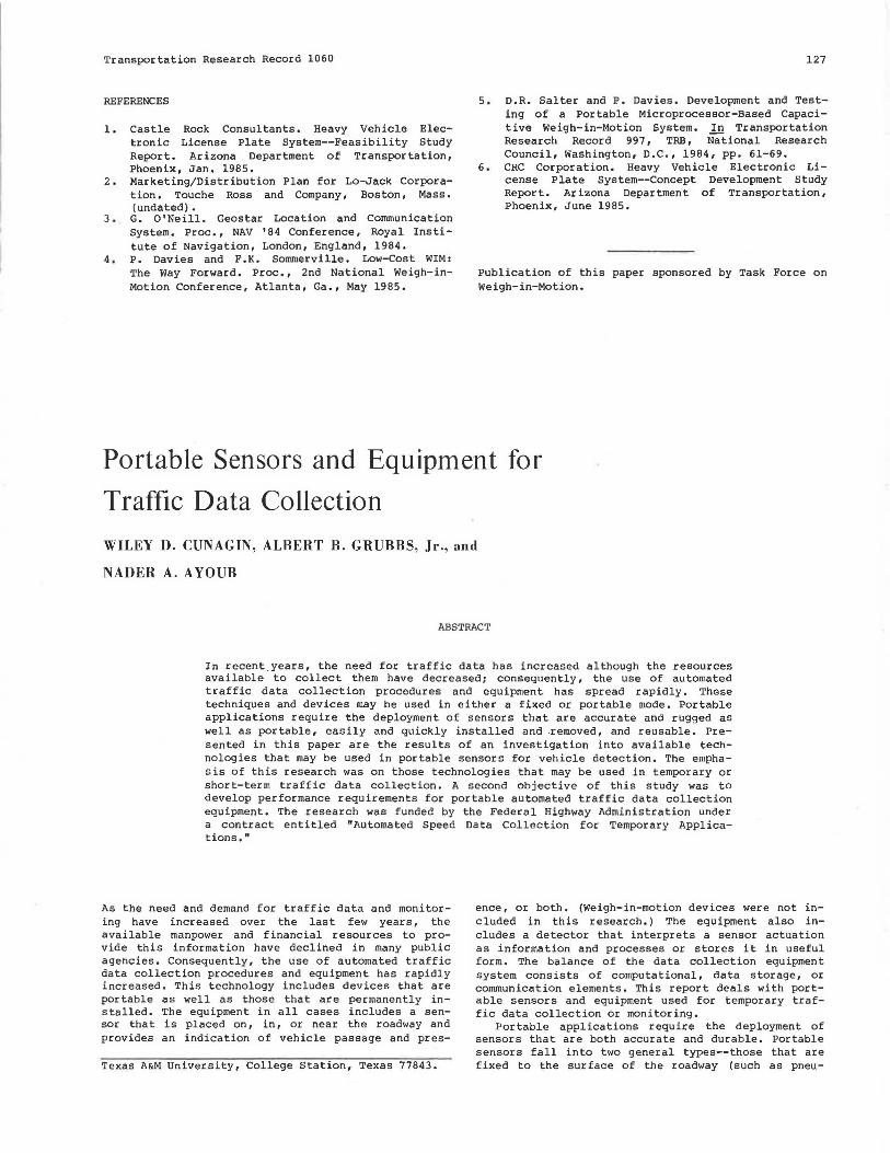
Pneumatic tubes have several important advantages. The first of these is cost. Lane-by-lane traffic data can be acquired on a two-lane highway using two pneumatic tubes, which cost approicimately $50 including hardware. These sensors are easily installed by one person in less than 10 min under low trafficvolume conditions. Placement of the pneumatic tubes requires only inexpensive nails and straps or clamps. Spare sensors are easily carried and lanes with unusual dimensions are easily accommodated. The pneumatic tubes are reusable and durable, especially those that have a D-shaped cross section as shown in Fiyure 1. Pn.,,um<ilic Lui.Jes under daily use and moderate traffic flow levels have an operational life of approximately 6 months.
D - Shaped Regular
@ FIGURE 1 Pneumatic tube cross section.
However, pneumatic tubes also have some significant disadvantages. Streets and highways that have heavy traffic volumes are not good locations for pneumatic tubes. The passage of a large number of axles may cause the device to work loose and could even create a hazard for traffic. In heavy traffic, there is a greater likelihood that two vehicles will pass over the pneumatic tube at approximately the same time, resulting in one actuation when there should have been two. The placement of pneumatic tubes under heavy traffic conditions is also hazardous to data collection personnel. Some difficulties have been experienced with the detection mechanism: pneumatic tubes placed side-by-side can vary by as much as 30 percent over a 15-min time interval. Pneumatic tubes are also susceptible to vandalism, both by drivers and by pedestrians. Drivers who lock their brakes as their tires pass over the tubes can rip the sensors out of place. Pedestrians have pulled up the pneumatic tubes.
Because this device is an axle detector, an adjustment factor must be applied to convert the number of axles into a vehicle count. This requires additional vehicle classification information.
Tapeswitches
Tapeswitches are essentially long narrow pairs of metallic contacts. The contacts are separated along their edges by insulation. The entire device is sealed in a waterproof vinyl sheath. The cost of one tapeswitch is approximately $30 if purchased in quantfties of ten or more. This device is fixed to the road surface with adhesives. In use with the FHWA' s Traffic Evaluator System, it is recommended that an anchoring tape with adhesive on both sides be placed in the road surface. The tapeswitch is placed on the upper surface of the tape and then covered with a protective and camouflaging second strip of tape (an olive drab-colored material was

Cunagin et al.
used in at least one study). It is not necessary to use the covering strip of tape for short duration studies with low traffic volume and little braking action by the vehicles. A material known as bituthene has come into increasing use in recent months for fixing portable sensors to the highway surface. Originally and principally used as a waterproofing material, it consists of a sheet of rubberized bituminous adhesive (bituthene) either alone or bonded to nonwoven or woven fabric. This material has been successfully used to fix tapeswitches to the highway by applying it directly over both the tapeswitch and the road surface, eliminating the need for doubles ided tape.
Tapeswitches have a low profile (approximately 3/16-in.) and are much less conspicuous than pneumatic tubes. They produce little audible or tactile feedback to the drivers of vehicles. Tapeswitches are portable, although installation and removal are more difficult than for pneumatic tubes. Total site placement for a two-lane location requires about 20 (versus 10) min for the tubes. Tapeswitches are slightly more durable on the highway than are pneumatic tubes, but some users have experienced as much as a 30 percerit loss of sensors with each removal. At this rate, the use of tapeswitches is much more costly than for tubes. The accuracy of data obtained from tapeswitches is significantly higher than is normally available from pneumatic tubes. The primary reason for this is the apparently inherent misoperation of many existing commercial pneumatic tube detectors. The switch closure of the tapeswi tch seems to be a much more reliable phenomenon to detect than is the operation of a diaphragm. For measuring vehi~ cle speeds, tapeswitches are generally much more securely fixed to the highway so that the exact separation between sensors is maintained. In contrast, pneumatic tubes come loose fairly often and even if they stay in approximately the same position, the relative distance between two tubes can vary, resulting in error in the speed calculations.
Piezoelectric Cable
Piezoelectric cable operates on the principle that electrical charge is generated when certain crystalline materials are subjected to stress. One type now in use is a coaxial cable with piezoelectric power as the dielectric material. For best results, piezoelectric cable (like the tapeswitch) used in temporary applications is fixed to the pavement surface with an adhesive. Consequently, the distance between two cables in a speed trap can be known to within ±1 percent, and the resulting speed calculations are also accurate to within ±1 percent. Of course, if care is not taken to maintain an exact separation, the accuracy will be less. Piezoelectric cable is sensitive, so care must be taken to minimize vibration and wind effects. The cable should be drawn taut and any excess active cable well secured. Loose cable can be moved by the wind resulting in false signals. For this reason, although the cable can be used by merely securing either end, the use of an adhesive is recommended.
Piezoelectric cable must be installed when the pavement is dry and warm enough for the adhesive tape to stick to the roadway surface. Manufacturers also recommend tape placement designs that allow water to pump out from under the tape during wet weather. Piezoelectric cables are not widely used in commercially available data collection systems nor in routine traffic data collection activities in the United States. However, they have been offered in the pas·t by at least one U.S. vendor and they have been used extensively in research studies. Piezo-
129
electric cable has been used extensively at fixed data collection sites in Europe, particularly in Germany and France. Piezoelectric cable is also readily adaptable to irregular roadway geometries because it can be cut to almost any length and connected to nonactive cable, which leads back to the traffic data collection equipment.
Piezoelectric cable sensors are as portable as tapeswitches, but less so than pneumatic tubes. Installation of both lanes of a two-lane roadway requires approximately 20 min. It is necessary to avoid cracks in the pavement that may create localized stress in the cable: alternatively, a piece of adhesive-backed fabric can be used to provide a bridge over a crack for the cable. (This is shown in Figure 2.) The need to carefully install the piezoelectric cable means that the data collection personnel must be in the traffic lane longer than they would for the installation of a pneumatic tube. As a result, the hazard to the workers is greater, particularly under high speed and high traffic volume conditions, or both. Removal of the piezoelectric cable also takes about 20 min for a two-lane site as a result of the need to carefully pull the bituthene from the cable.
Bituthene
d:;:=, ~.t;:;:=, ====::;,~ Sensor
FIGURE 2 Surface.mounted sensor cross section.
The vulnerability of a piezoelectric cable to vandalism is about the same as that for a tapeswitch and considerably less than for a pneumatic tube. The adhesive material is resistant to normal vehicular braking, but probably cannot withstand full braking across it by a loaded truck. The operational life of a portable piezoelectric cable sensor is about 6 months under normal operating conditions, assuming frequent installation and removal. The visual, audible, and tactile cons~icuities of the cable are similar to that of the tapeswitch and significantly less than that of the pneumatic tube. Piezoelectric cable costs about $400 for two lanes. The adhesive material costs an additional $10 per two-lane site.
Coaxial Cable
Coaxial cable without piezoelectric material as its dielectric has also been used as an axle detector. Use is made of the production of electrical charge due to friction between certain materials. Common varieties of commercially available coaxial cable such as that shown in Figure 3 exhibit this tr iboelectr ic effect when subjected to vibration or flexure. For permanent installation, the cable is encased in epoxy and placed in a slot in the pavement, which is then sealed. As a temporary sensor, the cable is used as is. Its use is analogous to the piezoelectric cable described previously.
FIGURE 3 Coaxial cable.

130
The accuracy of the temporary coaxial cable axle sensor is similar to that obtained with the piezoelectric cable. Like the piezoelectric cable, it can be stretched across the road and secured at each end, but better results are obtained if the cable is held in place with bituthene. The effects of wind and vibration can be significant for loose cable, resulting in false signals. If an adhesive such as bituthene is used, the cable must be installed under dry conditions when the temperature is above freezing. Interfacing the cable to available traffic data collection equipment should not be a problem because most of the u.s. vendors have been using coaxial cable experimentally ror several years. Coaxial cable is readily adapted to non~tandard roadway geometries because it can be cut to nearly any length and connected to a nonactive cable leading to the traffic data collection equipment.
Like piezoelectric cable, triboelectric coaxial cable is made less portable by the need to minimize the effects of wind and vibration. Removal requires care and the adhesive material must be removed and replaced for each installation. installation and removal each require about 20 min for a two-lane site. This puts the data collection personnel in an exposed position that can be hazardous under heavy traffic conditions. The probability of vandalism is about equal to that for piezoelectric cable: less than for pneumatic tubes but still significant. The operational life of a coaxial triboelectric cable is about 6 months unless a large number of heavy truck axles pass over it. The visual, tactile, and audible conspicuity are equal to those of the piezoelectric cable, but slightly less than for pneumatic tubes. It is in the area of cost that the coaxial triboelectr ic cable is most attractive. Sensors for a two-lane location cost a total of less than $20, which is less than the cost of pneumatic tubes and about 5 percent of the cost of piezoelectric cable. The adhesive material adds about $10 for a two-lane site.
The Inductive Loop
The inductive loop, consisting of one or more turns of insulated wire placed in a shallow slot in the roadway, is undoubtedly the most widely used permanent traffic sensor. It is simple, accurate, relatively inexpensive, and durable. In recent years, increasing attention has been directed toward adapting this technology to temporary traffic data collection.
Two different concepts have been used to produce temporary surface-mountt:oa inn1_H:~tiv'=' loops .. ThP- first involves fixing wire to the roadway surface with an adhesive material. One early approach to accomplish this consisted of (a) measuring and marking on the surface of the pavement the desired shape, size; and location of the loop; (b) driving nails at the loop corners; (c) winding wire around the rectangle formed by the nails; (d) covering the wire with adhesive tape; and (e) applying a waterproofing material sealant to the edges of the tape. A similar temporary inductive loop installation procedure replaces the tape and waterproofing sealant with the bituthene material described previously under the tapeswitch discussion. The bituthene is easier to apply than is the tape and waterproofing, but it also makes removal more difficult. Further development of this concept led to prefabrication of temporary loops. Common loop sizes are shown in Figure 4. Several vendors now offer these sensors at a cost of approximately $75 each, but it is possible for highway agencies that wish to use temporary surface-
Transportation Research Record 1060
FIGURE 4 Common dimensions of temporary loops.
mounted loops to make them at a cost of about $25 each including both material and labor.
A second approach to producing temporary inductive loops uses an industrial floor mat, which is approximately 3/8-in. thick. A shallow slot is cut from the underside of the mat in the desired shape and size of the loop. The wire is placed in the slot and an asphaltic sealant is used to permanently close the opening. This prefabricated sensor is then fixed to the road along its outside edges using bituthene strips. The Florida Department of Transportation has successfully used this method in conjunction with its portable dynamic truck weighing system.
Inductive loop technology has produced counting and speed accuracies as high as 98.5 percent. Because it is activated by the presence of the iron in a vehicle that enters its magnetic field, the inductive loop enjoys a significant advantage in vehicle counting as compared to the pneumatic tube, tapeswitch, piezoelectric, or triboelectric devices, which count axles. These latter devices can acquire only a total axle count that must be converted to a vehicle count by using data or assumptions about the distribution of the number of axles per vehicle. However, the accuracy of inductive loops is diminished by the presence in the traffic stream of trucks that do not have a significant amount of ferrous material throughout their lengths. For example, a tractor pulling a semitrailer designed to carry logs, concrete beams, or pipes will often appear as two separate vehicles to the inductive loop detector. The accuracy of inductive loops is also adversely affected by poor lane discipline. Depending on the georoetry of the l~n~s, vehicles in an adjoining lane may be erroneously detected.
Sensitivity can be a problem with inductive loops. Self-tuning circuitry is required in the detection equipment to compensate for drift. The difficulty in sensing some log trucks is due to the practical limit to the sensitivity of the detector circuitry. There is virtually no problem in adapting traffic data collection equipment to temporary inductive loops because nearly all of these devices are designed to work with permanently installed inductive loops and there is no functional difference between the permanent and temporary sensors. Inductive loops can be installed in a wide variety of shapes and sizes while still maintaining electromagnetic characteristics within the operational range of the detection circuitry. They are therefore adaptable to roadway geometry, although care must be taken to assure that only those vehicles tl)at are intended to be detected come within the effective range of the loop. The same environmental limita-

Cunagin et al.
tions apply to temporary inductive loops as for the previously described surface-mounted sensors: the surface must be dry and not below freezing. Once installed, traffic may be allowed to pass over the sensors immediately.
Portability is not a feature of the loops fabricated using only wire and bituthene. The loop is destroyed during removal and must be discarded. However, the inductive loop that is embedded in the industrial mat is readily removed, transported, and reinatalled. A preformed inductive loop can be installed in approximately 10 min. Removal requires about the same period of time if the sensor has been in place for l week or less. If it has been on the pavement for more than l week, or if the temperature has been above 90°F for a significant period of time, removal of an inductive loop made from wire and bi tuthene can take as long as l hr. Removal of the mat with the embedded loop takes about 10 min. It is not known at this time how long removal would take after longer and/or high temperature periods, but it should be easier than with the wire-bituthene loop.
Installation hazard is directly proportional to the time required to install the sensor. To this extent, prefabricated surface-mounted inductive loops are more hazardous than pneumatic tubes and about the same as the other previously discussed axle sensors. Inductive loops are less prone to vandalism than are pneumatic tubes, and similar to tapeswitches and piezoelectric cables in their degree of resistance to damage from this source. The visual, audible, and tactile conspicui ty of surface-mounted inductive loops are about the same as with the tapeswitch and piezoelectric cable sensors, but less than for pneumatic tubes, possibly for the reason that these three devices appear to be patched locations in the road although the tubes are clearly identifiable.
Radio Frequency
Radio frequency detectors have received attention for more than a decade. During the early 1970s, the New York Department of Transportation developed the Radio Frequency Traffic Sensor (RFTS) as a replacement for the pneumatic tube. The RFTS has two elements: a surface-mounted roadway sensor and a roadside receiver-decoder. The roadway sensor is powered by 16 nickel-cadmium, AA batteries and includes vehicle detection circuitry and a crystal-controlled transmitter and antenna. This assembly is encased in polyurethane. The roadway sensor is circular with a diameter of approximately 10 in. and a height of about 1.5 in. with an overarl shape similar to a large, raised pavement marker.
The RFTS functions in the following manner. A detection loop, which is 8 in. in diameter, ii> etched inside the roadway sensor and forms part of an LC detection oscillator circuit that operates at approximately 500 kHz. A reference oscillator is tuned to the same frequency as the detection oscillator. The presence of a vehicle passing over the detection loop causes a shift in the frequency of the detection oscillator. The result is that the transmitter circuit is activated and a signal is transmitted to the roadside receiver.
The roadside receiver includes a crystal-controlled superheterodyne receiver, a phase-lock loop, a decoder, and digital logic circuitry. When a signal is received from the roadway sensor, the phaselock loop is used to produce one pulse at its onset (when the vehicle enters the detection area) and another pulse as the signal falls (when the vehicle
131
leaves the detection area). An engineering model for the RFTS was produced but this promising work was terminated in 1975 as a result of the nationwide public agency budgetary crisis.
Although unproven in the field, this technology has several features that are attractive for temporary traffic collection applications. For example, it probably has an accuracy similar to that of inductive loops. The sensitivity of the RFTS is also not established, nor is the ability to reject false signals. The researchers had an early problem with detection instability because of temperature variation, but reported that this difficulty was successfully addressed. The RFTS has not been used with traffic data collection equipment offered commercially in the United States, so there would certainly be a delay in adapting the device for routine use. However' , the phase-lock loop employed in the RFTS emulates the output of the widely used inductive loop vehicle detector, so the incorporation of this device should not be a major effort for any vendor.
Portability is a strong point of the RFTS. The roadway sensor can be installed with one nail in less than l min, although the use of an underpad of rubberized asphalt (bituthene) for additional adhesive strength is probably advisable. The roadside unit can be quickly installed with no traffic hazard or interference. The roadway sensor can be removed in approximately 2 min. Because of the comparatively small size of the roadway sensor, the potential for vandalism is probably less than for any other type of surface-mounted traffic sensor. - The roadside receiver can either be incorporated into traffic data collection equipment or secured in the same fashion as that equipment. Assuming that the roadway sensor is installed between the wheelpaths in a lane, it should last at least l year before needing replacement. The roadside receiver should last several years. The visual conspicuity of the sensor is low and could be further minimized by the use of recent advances in battery technology. It should be possible to reduce the diameter of the roadway sensor electronics to less than 6 in., but provision must still be made for the proper size detection loop, which is presently 8 in. in diameter. The cost of a modified RFTS is not known, but should be less than $200.
Magnetometer
Magnetometer technology - has been thoroughly addressed by the FHWA in its development of a SelfPowered Vehicle Detector (SPVD). However, in its current configuration, it requires boring a hole in the pavement 4. 5 in. in diameter and 15 in. deep. The SPVD is placed in the cavity, which is then sealed. A major redesign effort would be required to adapt this device to surface-mounting and therefore to temporary traffic data collection applications.
Roadside-Mounted Portable Sensors
Like surface-mounted technologies, a wide variety of concepts have been used for sensing vehicles from above or at the side of the roadway. The most familiar of these devices is handheld radar. Other sensors that have been used include microwave, sonic, optical, infrared, video, laser, magnetic, seismic, and radio frequency devices.
Handheld Radar
Handheld radar is easy to use and is widely accepted. It is also theoretically accurate if aimed

132
directly at oncoming vehicles. The equipment is portable and may be operated from inside a vehicle. Although the initial cost of the radar unit can be as much as $3,000, the annual cost apportioned over the life of the device is not more than 10 percent of that cost. Handheld radar is easily operated by a single person. Probably the greatest advantage of radar is that it does not require placement of sensors on or in the highway surface.
There are also some significant disadvantages associated with handheld radar. If it is not pointed directly into the oncoming traffic (as it seldom is), an error is introduced that is proportional to the cosine of the angle between the vehicle's direction of travel and the direction in which the radar is aimed. This improper use is shown in Figure 5. It is also well documented that the use of the radar unit is detectable visually or electronically by vehicles in the traffic stream so that the average speeds may be reduced significantly by its use. The problem may be im:reai;ed by the ui;e of citizens' band radio to w;irn other driven; thilt nid;ir iR in use. The effectiveness of handheld radar is also influenced by the presence of large vehicles, which make the use of radar in heavy traffic conditions of questionable value.
-q
* Error is Proportional to cos 0. FIGURE 5 Example of handheld radar usage.
Perhaps the most serious disadvantage of radar is that it must be manually operated, although the radar concept has been used to produce nonportable sensors. Manual operation results in high labor costs as well as placing demands on a labor pool that is limited in these days of increasing pressure to reduce staff size and trim budgets. The need to operate the radar manually also restricts the sample size to a level that can be effectively acquired by one person in a reasonable study period. Samples that are taken during normal working hours may not ut:: represei-1LaLive or Llit: acLual UistriUution of speeds of all vehicles passing the survey point. In addition, if speeds are taken on a lane-by-lane basis, vehicles in the near lane may obstruct the acquisition of data from the far lane.
A modified form of radar technology uses a narrow, low-power microwave beam directed across the roadway at an angle of about 20 degrees. These devices have the advantage that individual speed readings can be obtained in even relatively heavy traffic. They are also more difficult to detect electronically because they do not broadcast their microwave energy down the roadway. This equipment is widely used in Europe, but its cost is approximately five times that of conventional radar.
Microwave Radar
Microwave radar is currently under study in research funded by the FHWA that is being performed by the Epsilon Lambda Electronics Corporation. The objec-
Transportation Research Record 1060
tive is to produce an upper microwave frequency radar system that can detect the presence and movement of vehicles at intersections. The researchers have tested a laboratory model of a unit that operates at a frequency of 24 gHz using a 24-in. antenna. The prototype device is being constructed using commercially available hardware that has moderate performance specifications. This device may be useful for, or adaptable to, temporary traffic data collection applications in the future.
Infrared Sensors
Infrared sensors are classified as either active or passive. Active infrared devices operate by using a semiconductor infrared generator to produce a narrow beam of energy in the infrared frequency band that is projected horizontally across the road onto an infrared-sensitive cell. The interruption of the heam hy ii veh i r.l e is interpreted by detection circuitry as vehicle presence and/or passage. Alternatively, the beam may be directed vertically down onto the road surface and reflected back up to the cell. A change in the level of infrared energy received by the infrared-sensitive cell can then be used to register the passage of a vehicle.
Passive infrared detectors register a change from the level of ambient infrared energy being received from the road surface. If the level of infrared emissions radiated by a vehicle is significantly different from that radiated by the pavement surface, the passage of a vehicle is recorded. Inf·rared detectors have not been widely used but ongoing research at the Texas Transportation Institute (TTI) funded by the Texas State Department of Highways and Public Transportation (in cooperation with the FHWA) directed toward development of an effective overhead vehicle sensor system, has recently become focused on passive infrared sensor technology. Mounting of this sensor is shown in Figure 6. Although this research is not specifically aimed at temporary traffic data collection applications, results to date indicate that the final device produced in that research will be useful for both permanent and temporary installations.
FIGURE 6 Mounting of overhead sensor.
Recent research at the Australian Road Research Board (ARRB) studied the usefulness of an active infrared vehicle detector in conjunction with the ARRB Vehicle Detector Data Acquisition System to acquire field data for use with their TRARR simulation model. The sensor system used by the ARRB consisted of an infrared transmitter-receiver unit directed horizontally across the roadway at either a pavement

Cunagin et al.
surface- or post-mounted reflector. The ARRB was attempting to detect axles.
The accuracy of infrared detectors depends on several factors. For active devices, the width and strength of the transmitted beam are important. The ARRB found that axle detection accuracy was adversely affected by low-hanging vehicle parts, which frequently introduced extra actuations. In trying to detect axles in both lanes of a two-lane facility, the ARRB attempted to align one surface-mounted reflector with a pole-mounted reflector at the same height as the transmitter unit. They found it difficult to maintain the alignment of the sensor system. The ARRB concluded that this device is much more accurate as a vehicle detector than as an axle detector. The accuracy of this configuration is also diminished by the probability that two vehicles will pass the detection point at exactly the same time.
The accuracy of the passive overhead vehicle detector is affected by the width of the field of influence from which infrared energy is received. It is necessary to use a parabolic reflector with the infrared sensing element directed inward if a suff iciently narrow field of influence is to be attained. Hardware or software provisions must also be included to (a) compensate for changing ambient infrared energy conditions, (b) filter out noise due to sonic or mechanical vibration or electromagnetic interference, and (c) provide for properly interpreting variation in infrared emissions from a single vehicle, as with a tractor with a semitrailer.
Environmental conditions are important to both active and passive infrared detectors. Although the roadside transmitter-receiver and the post-mounted reflector can be installed in wet weather if necessary, the surface-mounted reflector must be installed during dry conditions with the temperature above freezing if commercially available adhesives are to be used. The presence of dust and dirt is a major consideration for either passive or active infrared sensors, although this restriction is not significant in the case of most temporary traffic data collection activities. Interfacing with commercially available traffic data collection equipment may be a problem in some cases because infrared detector inputs are not a normally offered i tern for any products now offered in the United States. It will be necessary for the user to construct or otherwise obtain the necessary sensor interface. The overhead vehicle sensor under development at TTI will produce an output that is seen by traffic data collection equipment as a switch closure, thereby allowing its use with all commercially available equipment.
Adaptation of the infrared sensor to a wide range of roadway geometric conditions is difficult. Whereas the active horizontal infrared sensor may be adaptable to two-lane roads, the presence of a crown in the cross section or atypical geometry will present a challenge to the user. Likewise, if the overhead sensor is to be effective for lane discrimination, it is necessary to position one detector directly over each lane. This will be difficult to accomplish if no overhead structures are available at the desired location.
Portability is good for the active horizontal infrared sensor. The roadside elements can be quickly set up without significant interference to or from the traffic stream. The surface mounted reflector can be attached within one or two minutes. The hazard of installing a portable sensor is therefore greatly reduced. The portability of the overhead sensor is limited by the necessity to have an overhead structure suitable for supporting the device. However, if a supporting structure is available, in-
133
stallation and removal may not require any intrusion into the lanes of travel.
Vandalism should not be a problem with either of these two devices. Both are inconspicuous and should not be apparent to destructive persons. In addition, because they are not located in the main lanes, destruction by vehicles is not likely. One possible exception to this is if a driver intentionally or accidentally leaves the road and runs over the active infrared transmitter-receiver or reflector units.
The cost of the horizontal active infrared transmitter-receiver unit is approximately $200. The cost of the reflector uni ts should be less than $20. It is expected that the passive infrared overhead sensor unit can be sold for less than $100.
Photoelectric Sensors
Photoelectric sensors are analogous to the infrared devices described previously under active infrared technology. These devices cannot be operated in a passive mode for traffic data collection. That is, they require a light source that must be interrupted or reflected to produce an actuation. Light beams are also visible (while infrared beams are not) so that conspicuity may be a minor problem for photoelectric sensors. In all other ways (i.e., accuracy, sensitivity, ability to reject false signals, environmental limitations, interfacing with traffic data collection equipment, adaptability to the roadway, portability, installation and removal, hazard of installation, operational life, and cost), the discussion for infrared sensors also applies to the photoelectric devices.
Laser Radar
Laser radar is being used in a wide range of applications and at least one vendor is offering a laser radar traffic detector. The term "laser" is an acronym for "light amplification by stimulated emission of radiation" while "radar" means "radio detection and ranging." A laser is produced by a device that contains a crystal, gas, or other material in which atoms are stimulated by focused light waves. These 1 ight waves are amplified and concentrated into a narrow, intense beam. Conceptually, traffic detection products that employ this technology will operate in the same fashion as the active infrared device described in the preceding paragraphs. That is, the laser beam is produced and transmitted. A vehicle is then sensed by either interruption of the beam or by its being reflected back to a combined transmitter-receiver unit. The advantages and disadvantages of these devices are also similar to those found with the active infrared sensors. However, the cost of these devices is much higher than that of infrared sensors while their performance has not yet been established in the highway environment. Maintenance and repair of these sensors might be a problem because it is unlikely that any highway agencies will have technical personnel on hand who are qualified to perform this task. They are not now offered by any vendor in the United States and reasonable repair service is not available. On the positive side, laser radar technology is advancing rapidly and both cost and availability of sensors based on this concept should improve dramatically.
Present designs of laser radar sensors use a tripod to support a combined transmitter-receiver unit. This device is portable and reportedly is accurate to within 1 mph. The environmental limitations are the same as those for the active infrared sensor and

134
may be more severe as a result of the narrow laser beam, Adaptation to the roadway is potentially better than with infrared devices because the laser can be precisely aimed and can also detect distance. It can also be used in a manner analogous to the narrow beam radar used in the "cross-the-road" microwave radar application described in the preceding section on handheld radar.
Portability is a strong advantage of tripodmounted laser radar but also presents a potential problem of vandalism. The units are new and will probably continue to be too costly to leave unattended, with the result that the system cannot be used efficiently for automated traffic data collection. Visual conspicuity can also be a problem unless the highway agency is particularly careful and creative in devising a method to camouflage the device.
COMPARATIVE ASSESSMENT OF TECHNOLOGIES
The fo r ego i ng portable traff i c sensor technol ogies were evaluated and ranked with respect to the previously defined criteria as follows:
A. Technical Effectiveness 1. Accuracy 2. Sensitivity
TABLE 1 Comparative Assessment of Portable Traffic Sensor Technologies' Technical Effectiveness
Rejection Environmental of False
Sensor Accuracy Sensitivity Limitations Signals
Surface-mounted Pneumatic tube s s s s Tapeswitcl) 8 8 s 8 Piezoelectric cable 8 IO 5 5 Coaxial cable 8 5 5 8 Inductive loop 5 5 5 5 Radio frequency 5 5 5 5
Overhea d-rou dsid e Handheld radar 3 3 Microwave radar Infrared (active) 5 7 7 7 Infrared (passive) 5 6 5 Photoelectric 5 7 7 Laser radar 7 7 7
Note: Higher rankings indicate stronger beneficial qualities. For example, a sensor with a higher rating under "environmental conditions" would be able to withstand poor environmental conditions. 3 Information not yet available.
Transportation Research Record 1060
3. Ability to reject false signals 4. Environmental limitations
B . User Acceptance 1. Portability 2. Ease of installation and removal 3. Hazard of installing 4. Vandalism 5. Operational life
c. Cost 1. Original purchase 2. Installation and removal 3. Maintenance
The results are given in Tables l and 2. Based on this analysis, piezoelectric cable, infrared, and laser technologies were recommended for further development as temporary traffic data collection sensors.
PERFORMANCE REQUIREMENTS
Performance requil:emenls for porlable sensors and traffic data collection equipment were developed based on published and unpublished studies, information obtained in interviews of practicing professionals actively involved in routine traffic data collection, and the experience of the research staff in traffic data collection equipment, procedures, and technology. The performance requirements for sensors and equipment are presented in the following sections.
Po r tabl e Sens o i: Per f o rmance Re q uiremen t s
The perfoi:mance criteria developed for poi:table sensors for traffic data collection include the following factors:
1. Portability; 2 . Response time and sensitivity; 3. Overall accuracy; 4. Envii:onmental limitations (such as tempera
ture range and weather conditions) ; 5. Size and placement considerations (such as
conspicuity, vulnerability to deliberate destruction, and adaptability to vai:ious lane configurations and other geometric features);
6. Cost (initial, installation, i:epair, and maintenance);
7. Ease and hazard of installation and i:emoval, and limftations with respect to pavement surfaces; and
TABLE 2 Cornparath·e Assessment of Portable Traffic Sensor Technologies' User Acceptance and Cost
Sensor Portability Ease of Use Installation Hazard Vandalism Operation Life Cost
Surface-mounted Pneumatic tu be 8 8 s s 7 9 Tapeswitch 6 5 5 7 s 6 Piezoelectric cable 6 5 s 7 8 5 Coaxial cable 6 5 s 7 5 8 Inductive loop 6 5 4 5 7 8 Radio frequency 6 4 6 7 7 5
Overhead-roadside Handheld radar 8 8 9 9 9 5 Microwave radar • Infrared (active) 6 7 5 7 5 Infrared (passive) 6 9 9 7 6 Photoelectric 6 7 5 7 5 Laser radar 6 7 5 7 4
Note: Higher rankings indicate stronger beneficial qualities. For example, a sensor \vith a higher rating under "vandalism" would be less vulnerable to vandalism. 3 Information not yet available.

Cunagin et al.
8, Operational life.
These er i ter ia are each des er ibed in the following discussion.
Portability
Portability is an important consideration. The sensor must be designed and packaged such that one person can easily handle it. In addition, it is common practice for one data collection person to set up as many as 40 temporary traffic data collection sites in a single day. Because all equipment must be transported in a single station wagon or cargo van, the sensors must be small enough and rugged enough to withstand daily handling as well as traffic wear.
Response Time and Sensitivity
Response time and sensitivity become especially important as the traffic volume and speed, or both, increase. The response time for sensors should be short to allow each actuation to be processed in time for another closely following actuation. The worst case of this condition occurs when an axle detector extends across two lanes that can each have traffic at that point at exactly the same time. Obviously, if the two vehicles actually hit the same sensor at the same time, it is not reasonable to require that device to give two outputs, although some sensors such as piezoelectric cable are theoretically capable of providing information for doing so. Instead, because most commercially available traffic data collection equipment is capable of resolution to l msec, that value is recommended as the total time to be required for a portable traffic sensor to respond to the physical stimulus that it is designed to detect and also to recover when the stimulus is removed.
Sensitivity has both positive and negative aspects. Pneumatic tubes often suffer from a lack of sensitivity so that they have been observed to undercount axles by as much as 30 percent. On the other hand, piezoelectric cable, which is not firmly secured to the roadway surface, can be subject to wind effects that result in overcounting. It is therefore recommended that vendors of portable traffic data collection devices should provide detailed application guidelines that advise the user as to the best procedures for installing the sensors that are compatible with their equipment. Alternatively, the FHWA, NCHRP, or individual states may wish to prepare generic application guidelines for using portable traffic sensors.
Overall Accuracy
Overall accuracy of the portable sensor sets a limit on the attainable accuracy of the data collection system. It is imperative that traffic counting sensors measure the phenomenon they are designed to detect, whether it be axle passages or vehicle passages, within no less than ±10 percent at the 95 percent confidence level. The accuracy of event times, required for calculation of speed, should be within l msec at the 95 percent confidence level, as previously indicated under response time. This will result in a theoretical possible accuracy of approximately l percent for vehicles traveling at 60 mph through a speed trap with a spacing of 16 ft between sensors.
135
Environmental Criteria
Environmental criteria are more difficult to define. The axle sensors that are capable of the greatest accuracy also require the use of adhesive materials that cannot be effectively applied to wet or freezing surfaces. However, once these devices are installed, they generally can withstand moderate amounts of rainfall and short periods of belowfreezing temperatures. Wet, frozen, or snow-covered surfaces can also affect the performance of devices that depend on reflected energy because the ambient levels of the energy being measured may be approximately equal to those derived from a vehicle that passes by the sensor. Rainfall or snowfall can also impair the transmission and reception of roadside sensors.
It is not possible to prescribe uniform environmental performance requirements for all portable sensors, but it is reasonable and desirable to define a range of performance tests that portable sensors must pass before they are included in a list of acceptable devices from which a public agency will select acceptable products for procurement. Standard tests that cover the range of environmental conditions in which a device must function effectively are needed. It is recommended that simulated passages of vehicles be used in combination with conditions that create adverse effects similar to those that are of concern. For example, infrared detectors could be tested by using specified filters between moving sources of infrared energy and the sensor and recording the number of successful actuations. The definition of specific performance requirements should be based on the criterion that under some minimal environmental condition, axle or vehicle counting accuracy, depending on which quantity the device measures, should be within 10 percent at the 95 percent confidence level. Likewise, event times should be accurately recorded within ±1 msec at the 95 percent confidence level.
Size and Placement
Size and placement are two related critical factors. In addition to the impacts of these considerations on installation and removal (a discussion follows) the performance of portable traffic sensors with regard to conspicuity, resistance to destruction, and adaptability to different lane configurations must be addressed. It is widely accepted that an effective sensor should not affect the phenomenon that it is measuring. In the traffic data acquisition context, it has been shown that the use of radar directed down the roadway very quickly results in lower speeds as drivers become aware that they are being monitored. The conspicuity of portable traffic data collection sensors is therefore an important performance variable. Axle sensors are the most conspicuous class of portable sensors. They provide visual, audible, and tactile feedback to the drivers. It has not been shown, however, that these devices significantly affect traffic speeds, possibly because they are routinely encountered without concurrent enforcement activity. Nevertheless, it is advisable to apply some sort of camouflaging material to sensors, if possible. This is not reasonable with pneumatic tubes, but the adhesive material, which is sometimes applied over tapeswitches, piezoelectric or triboelectric cable, and surface-mounted inductive loops, is effective for this purpose. Roadside or overhead sensors should be placed ori existing structures where possible or else made to resemble typical roadside features. New portable sensors to be offered for sale should be tested to

136
determine whether their presence affects the traffic. Speeds could be acquired using a candidate at a location where permanently installed inductive loops exist and before and after data are available.
Vulnerability to deliberate destruction is another difficult characteristic to measure. Any portable sensor can be damaged, but the stronger it is held in place, and the less conspicuous and accessible it is, the better. Surface-mounted devices should be designed to be fixed to the pavement with adhesive. Roadside sensors should be encased in tough housings that are resistant to destruction and these should be secured to a permanent feature of the roadside with a heavy lock and chain or other similar mechanism.
The sensor should be adaptable to a variety of lane configurations and geometric features. The active sensor element should be restricted to the area of interest with nonactive cable (or some other communication means) connecting it to the traffic data collection equipment. The pneumatic tube is an excellent example of a sensor that does not conform to this requirement. To count traffic separately in each of two lanes, it is necessary to run one tube across the near lane and another across both lanes, connecting both pneumatic tubes to the same traffic data collection device. Lane volumes for the far lane are computed by subtracting the volume for the near lane.
Costs
Costs are directly obtainable after using a sensor for a short time. However, care must be taken to include all costs associated with using a particular device. For example, triboelectric coaxial cable costs about the same as pneumatic tube but can take twice as long to install. The mean time between failures, average repair cost, and average down time all have significant cost implications. Comparisons among sensor alternatives must include fully allocated costs. The sensor comparisons of Table 1 include relative costs among available and potential sensors.
Installation and Removal
Installation and removal requirements have important safety and cost impacts. It is clear that an effective portable sensor must be installable and removable in not more than 30 min, preferably not more than 20 min. For surface-mounted sensors, the installation procedure must be aesignea so tnat one person can install the device without losing concentration on approaching traffic. Otherwise, traffic control is necessary and the device will have only limited applicability. Similarly, the installation procedure must allow the data collection person to leave the partially installed sensor in the traffic lane while traffic passes over it. The sensor installation procedure must also take into account surface irregularities and provide for installing the device in less than perfect conditions. For example, tapeswitches, piezoelectric and triboelectric cable, and surface-mounted inductive loops all require a "bridge" over discontinuities in the pavement surface to prevent damage to the sensor as a result of localized stress.
Operational Life
Operational life has important cost as well as operational impacts. An inexpensive sensor that must be
Transportation Research Record 1060
replaced every month can have a higher annual cost than a device that is expensive yet lasts for several years. Practically speaking, though, an effective sensor should last at least 6 months and amortization of the cost of a portable sensor should be for not more than 3 years.
AUTOMATED TRAFFIC DATA COLLECTION PERFORMANCE REQUIREMENTS
Automated traffic data collection devices must operate in conjunction with effective sensors to acquire and store traffic data in a usable format. Performance requirements for this equipment include the following factors:
• Traffic data output; • Accuracy range; • Operational range (road, traffic, and envi-
ronment); • Portability; • Cost; • Capacity; • Conspicuity and resistance to vandalism; and • Ease of operation.
These er i ter ia are described in the following discussion.
Traffic Data Output
Traffic data output is an essential consideration. It involves a direct tradeoff with capacity and cost. The traffic data collection device should do the job that needs to be done at the lowest possible overall long-term cost. This may not be, and probably is not, the lowest initial cost. It should also be adaptable to a wide variety of types of studies and be flexible in the parameters available. This last consideration complicates the isime of ease of operation because the requirement to make many decis ions to set up the equipmen·t may detract from its usability. It is clear, however, that for traffic counting, daily, preferably hourly, totals by lane are needed. Recent changes to statewide traffic counting programs suggested by the FHWA Traffic Monitoring Guide point to wider use of 48-hr counts rather than 24-hr counts. Because traffic volumes fluctuate significantly by day of the week, it is necessary to have daily or hourly totals in order to properly apply daily adjustment factors. Speed data collection devices should offer the capability to obtain speed distribution~ Uy vehicle: type (at least a separation of cars from trucks) and the option to get the speed distributions of free-flowing and nonfree-flowing vehicles using a headway threshold value specified by the user.
Accuracy
Accuracy within the traffic data collection device should not diminish the accuracy obtainable from the sensor. A resolution of 1 msec for event times seems to be standard in the industry and this value is acceptable as a performance requirement. "Binning" (i.e., sununing data into categories rather than storing discrete events to preserve memory) does not seem to have a significant adverse effect on accuracy. The traffic data collection device must record sensor actuations with an error rate of not more than 1 percent at the 99 percent confidence level. This should not be confused with the sensor accuracy, which is a lesser value.

Cunagin et al.
Operational Range
Operational Range of the equipment should include the expected road, traffic, and environmental conditions commonly found in the United States. It must be resistant to dust and humidity as well as rain. The traffic data collection equipment should function without diminished performance for temperatures in the range of -40°F to 160°F. It should operate on battery power for at least 180 days when used with two pneumatic tubes to acquire traffic volume data from two lanes, storing hourly totals by lane in its memory. The equipment should acquire traffic volume or speed data when vehicles are passing at a rate of one every 1.5 sec at 60 mph while maintaining the accuracy specified in the previous section. The number of lanes of data to be acquired is an optional parameter. In some cases, an axle counter input is sufficient.
10 , 9
8 ~ ' ' I-
z 7 UJ :;; CJ)
6 CJ) UJ CJ) CJ) <{ 5 UJ
~ 4 I-<{ a: <{ 3 0-:;; 0 2 (.)
' ' ~ ' ~ ~ !iii II
~ - ~ ~ " i,i J i.-i,i '; 'J i.-
' ~ ~ i.-I II
' ' ' II
' ' ' II
' ' ' ~ WI ' ' ~
II ~ :, '
" i.-i.-i.-i.-i.-II II ~
'
137
Portability
Portability is absolutely necessary for automated traffic data collection equipment to be used for temporary applications. As described earlier, it is common for data collection personnel to set up as many as 40 sites per day. The traffic data collection equipment must be easily carried by one person, small enough so that all of the equipment can be transported in a station wagon or a cargo van, and rugged enough to withstand the handling.
Cost
Cost is dependent on the features included in the device, the quality of construction, and the level of support offered by the vendor. it is clear, however, that a full-featured product can be purchased
- " II II i.-II '; II '; ~
'
-
LEGEND
~ACCURACY rzzl SENSITIVITY
~ ENV. LIMIT.
D REJ . OF SIGNALS
0 -PN~IClP'iEz. CAB~NO. LOOP-i
TAPES'w1TCH COAXIAL CABLE RADIO FREQ.
SENSOR
FIGURE 7 Portable traffic sensors' technical effectiveness (surface-mounted).
10 LEGEND
9 ~ACCURACY
8 rzz.J SENSITIVITY I-z ~ ENV. LIMIT. UJ :;; 7
D gi REJ. OF SIGNALS UJ 6 gi <{
UJ 5 ::: I- 4 <{ a: <{
3 0-::;; 0
2 (.)
o.1._----;;~~~~~:!:-l!:~~~~~~ HANO. RADAR /1NFRAREO (PASS .) LASER RADAR
INFRARED (ACT.) PHOTO LECTRIC
SENSOR • MICll':OWAVE fU.OAR INFO. NOT AVAILABLE
FIGURE 8 Portable traffic sensors' technical effectiveness (overall-roadside).

138
10
9
8 I-z w 7 :::;; !:l 6 w (/) (/) <(
5 w > ; I- 4 <( ' IC <(
3 0.. :::;; 0
; ; ;
u 2 ; ; ; ;
E
~ • ' ' ; ;
; ; ; ; ; ; ; ; ;
' ; ~-' ; ;
• ~ ~ ; ; ;
~ ; ;
Transportation Research Record 1060
LEGEND
PORTABIUTY
EASE OF USE
INSTAL. HAZARDS
VANDALISM
OPER. LIFE
COST
0 ~-
PNEUMATICTPiEz:-cA"BLE I IND. LOOPI TAPE'.SWITCH COAXIAL CABLE RADIO FREQ
SENSOR
F1GURE 9 Portable traffic sensors' user acceptance and cost (surface-mounted).
10
9
I- 8 z w 7 :::;; !:l w 6 (/) (/)
i ; ~ :; :;
<( w ~ ~ I- 4 <( a: <( 3 0..
' ' ;
' ;
' ; ~
~ = ; :::;; 0
2 u ; ;
' ; :; ; :; ; = :; ;
0
=
; ; ; =
' =
' ' ; ; ; ; ; ; ; ~ ; ; :: ; ;
;
' ~ 'f
' :; :; :; ;
LEGEND
PORTABILITY
EASE OF USE
INSTAL. HAZARD
VANDALISM
OPER. LIFE
COST
--HAND. RADAR /1NFRARED (PASS.) j LASER RADAR
INFRARED (ACT.) PHOTOELECTRIC
SENSOR
• "'ICAOWAVE AAOAA INF"O. NOT AVAIL.ABLE
FIGURE 10 Portable traffic sensors' user acceptance and cost (overhead-roadside).
for less than $2,500, and a single function trattic counter or speed classifier can be obtained in bid quantities ot approximately 6 or more for less than $1,000. These devices may require a data retrieval device, which costs about $2,500, but can be used with between 6 and 12 data collection machines.
Capacity
Capacity of traffic data collection equipment is directly related to the method of data storage. Maximum memory size for commercially available devices is approximately 48,000 bytes. Data are usually stored as totals in a manner selected by the user. The time interval, number of channels, and number of lanes all contribute to the useful capacity of the devices. With worldwide, solid-state memory prices falling dramatically, it is reasonable to require that all traffic data collection devices have a memory capacity of 48,000 bytes. It is likely that the available memory will increase dramatically in the near future.
conspicuity
Conspicui~y and resistance to vandalism are important. The traffic data collection equipment should be housed in a tough enclosure that can be chained to a roadside feature using a tough lock and chain. It should also be painted a color that is likely to blend in with its surroundings.
Ease of Operation
Ease of operation has significant impacts on both cost and capacity. The most usable equipment devotes memory space that could be used to store data to a program that aids the data collection personnel in setting up and transferring data from the equipment. It is necessary, however, to make the operation of the device easily learned by nonexpert personnel. It is therefore recommended that the traffic data collection equipment include the following features: execution of a startup program that prompts the operator about (a) the required set-up parameter

Transportation Research Record 1060
values, (b) a limited pinpoint problems, and transferring the data.
CONCLUSION
self-diagnostic program (c) prompts to assist
to in
The use of automated traffic data collection procedures and equipment has increased rapidly as demand for data has grown while available resources have not. Recent developments in portable traffic sensor technology may be of use in improving the efficiency of acquiring these data. This paper has reviewed several aspects of possible technologies that may be applied to this need. The results of this paper are shown in Tables 1 and 2 as well as in Figures 7, 8,
139
9, and 10. Piezoelectric cable, infrared, and laser sensors were identified as having potential for increased use in temporary traffic data collection applications.
Performance requirements for portable sensors and traffic data collection equipment were developed based on a variety of sources. The need to consider standards for these devices is apparent and should be pursued to provide both users and vendors with guidelines.
Publication of this paper sponsored by Task Force on Weigh-in-Motion.
Multivariate Analysis of Pavement Dynaflect Deflection Data
JOHN G. ROHLF and RAMEY O. ROGNESS
ABSTRACT
Pavement management has become an area of great concern for highway departments. Pavement evaluation and research play an important role in the pavement management process. In this study, a relationship was developed between Dynaflect deflections and pavement temperature, subgrade moisture, and cumulative traffic loading for a number of different pavement sections. Dynaflect deflections and pavement surface temperatures were recorded for 76 flexible pavement sections·. The data were collected over a 9-year period on a North Dakota State Highway Department test road. A subgrade moisture classification was developed and used as a surrogate measure of subgrade moisture. The 5-day mean air temperature, in addition to the surface temperature, was used to represent the overall pavement temperature. The five Dynaflect sensor readings were found to be highly correlated. As a result, multivariate analysis techniques were used to analyze the data. Season (moisture), pavement surface and mean air temperatures, and traffic were found to significantly affect pavement deflection. The effects of temperature were significantly different for the different seasons.
Pavement management has become an area of great concern for highway dependents. As available resources and funds decrease, and a majority of roadways reach a state of severe deterioration, highway departments are no longer able to manage their roadways based on experience alone.
PAVEMENT MANAGEMENT
It has become apparent that in order to maximize the benefits of limited budgets, highway departments
J.G. Rohlf, FHWA, Western Federal Direct Office, Vancouver, Wash. 98770. R.O. Rogness, Transportation Technology Transfer Center, North Dakota State University, Fargo, N.D. 58105.
must develop extensive pavement management systems. In recent years, highway departments have begun to realize the importance of pavement evaluation and research in the pavement management process. Many highway departments have established control or evaluation roadway sections. Data related to pavement performance are periodically measured and recorded in a data bank.
In general, the data collected through pavement evaluation activities can be classified into the following four groups (_!) :
1. Roughness (ride quality), 2. Surface distress (impending failure),