Embed Size (px)
Citation preview
Aseismic hybrid control for
high-rise buildings
Y.P. Wang
Department of Civil Engineering, Chung-Hua
Polytechnic Institute, Hsin-Chu, Taiwan 30067,
ABSTRACT
Presented in the paper is a hybrid control system, referred to as the activeisolation system, consisting of rubber bearings as base isolators and a hydraulicactuator to monitor the base motion of the isolated structure. A predictivecontrol strategy is considered for control design of the active system. Thisalgorithm is developed specifically for relative response reduction ofbase-isolated structures subjected to seismic excitation. Effectiveness andadaptability of the proposed system is verified through numerical examples.Influences of the design parameters and time delay on the control efficacy aswell as the stability issue are discussed. Moreover, its performance is comparedwith that of a hysteretically damped base isolation system. Superiority ofincorporating active devices over passive ones is clearly demonstrated.
INTRODUCTION
Base isolation has been widely accepted for seismic design of buildingstructures in recent years. Application of this structural control scheme,however, is limited to low-rise buildings only due to problems of excessivebase displacement or high overturning moment. The former poses difficultiesin design and maintenance while the latter may give rise to structural instability.While introduction of energy dissipation devices such as friction dampers orhysteretic dampers may mitigate the problem of base displacement, theoverturning problem, however, can not be resolved simultaneously.Application of active control technique for seismic protection, on the otherhand, has also been extensively studied over the past two decades and hasreached the stage of full-scale implementation to date . An effective active
Transactions on the Built Environment vol 3, © 1993 WIT Press, www.witpress.com, ISSN 1743-3509
720 Soil Dynamics and Earthquake Engineering
system, however, may require a great deal of energy supply in proportion to thestructure's weight ™. Hence, it is economically impractical to use this type ofaseismic system alone for large-scale buildings.
Very recently, researchers have been focusing on hybrid control systemswhich tend to retain the merits of both active and passive systems with then-drawbacks mutually compensated. For instance, using rubber isolation systemassociated with hydraulic actuator or active mass damper ""' or slidingisolation system associated with the above mentioned active devices l Mostresults indicate that hybrid control systems are more effective and practical. Afew of the proposed systems have been tested in the laboratory. Due toproblems of either capacity limitation or neglecting the effect of time delay, theexperimental results are not as good as expected .
In this paper, a hybrid control system referred to as the active isolationsystem is proposed for seismic design of tall buildings. This system consists ofrubber bearings as base isolators and a hydraulic actuator to monitor the basemovement. The predictive control algorithm " is considered for the controldesign of the active system. It is developed specificly for relative responsereduction of base-isolated structures herein. Formulated in discrete-timerepresentation, this algorithm can easily account for the effect of time delayand can be directly implemented for on-line control. Effectiveness of theproposed system is verified through numerical simulation. Influences of thedesign parameters and time delay on the control efficacy as well as structuralstability are analyzed. In addition, analyses of the optimally designed systemare carried out under earthquakes of different characteristics to verify itsadaptability. Moeover, the performance of this system is compared with that ofa hysterically damped base isolation system. Superiority of incorporatingactive devices over passive ones is clearly demonstrated.
MODELING AND ANALYSIS OF CONTROLLED BASE-ISOLATEDSTRUCTURES
Equations of Motion and solution algorithm
The governing equations of the superstructure of a base-isolated building areexpressed in terms of relative coordinates with respect to the base in thefollowing form:
M%(f ) + C;t(f) + f z(f ) = -Ml(f»(f )+%,(,)) (1)
in which M = the superstructure mass matrix, C = the superstructure dampingmatrix, K = the superstructure stiffness matrix, and J_ = the vector ofearthquake contribution coefficients with all elements being 1. x& = the base
acceleration relative to the ground and x^ = the ground acceleration.
The equation of motion of the base is as follows
) = w(f ) (2)
where M&, C& and K± are respectively the mass, damping and stiffness of the
base. u(t) represents either the active control force or the passive restoringforce depending on whether the hydraulic actuator or the hysteretic damper is
Transactions on the Built Environment vol 3, © 1993 WIT Press, www.witpress.com, ISSN 1743-3509
Soil Dynamics and Earthquake Engineering 721
applied. Modeling of these elements will be discussed in the followingsections. Furthermore, *>(*) and %&(;) denote the base displacement and thebase velocity respectively.
Combining (1) and (2), the following equation is derived:
w MI ifx(t)\ rc
or in short,
(36)
Equation (3) can be reformulated in state space representation as:
(4)
where (5)
X
Equation (4) can be solved analytically in a discrete-time recursive formprovided the continuous time evolution of u(i) and Xg(i) over the samplingperiod [kjc+l] are known. A zero-order interpolation for the forcing functionu(i) and a linear variation for the ground excitation jc (r) gives
) (6)
where W*(k) is a vector associated with the ground motion given by
jf(A)] (7*)
The discrete system matrix A* and the control matrix B* with sampling periodAr are defined as
(76)
In equations (7), matrix PI =A"*(A*-7) and P2 = A"*(jPi- A*).
Active Control Element: Predictive Control Algorithm
The active control force is obtained by adding up the available structuralresponses filtered with proper feedback gains which in turn are determined inaccordance with a chosen control rule. In this study, the predictive controlalgorithm is considered. Formulation of the predictive control strategy startsfrom the discrete-time response of the dynamic system in (6) with a time lagimposed in the control signal to accommodate the time delay required forcontrol execution using the hydraulic system in real-time application. That is
Transactions on the Built Environment vol 3, © 1993 WIT Press, www.witpress.com, ISSN 1743-3509
722 Soil Dynamics and Earthquake Engineering
) (8)
in which d is an integer number of sampling intervals representing the timedelay. Based on the concept of predictive control, the control signals aredetermined by minimizing a cost function which penalizes the output state ofthe system at instant k + 'k + d and the control signal u(k\ X being thepredicting length from k. The output sequences during the prediction intervalare estimated using the predictive model defined by
t(k +j | k) = A*Z(k +j - 1 1 *) + B*tf(i +y - 1 -d \ k) (9a)
(96)
where Z(k +y | k) and Y(k +/ | k) are, respectively, the full state and the outputstate vectors predicted at instant k for instant k +j and u(k +j - 1 -d) is thecorresponding control vector sequence. Q being the output matrix. It is notedthat in this predictive model the ground excitation is excluded since it isunknown during the predicting process.
Model (9) is redefined at each instant k from the measured state Z(k) and thecontrol values u(.) prior to instant &, that is
(10a)
u(k-j\k) = u(k-j) (/ = l,...,d) (106)
Control signal u(k) is obtained by minimizing a cost function J defined by
J=^(k+\ + d\k)QY(k + \ + d\k)^u^(k\k)Ru(k\k) (11)
with the condition
(/ = 1,.-A) (12)
that imposes a constant control sequence on interval [k,k + X]. Weightingmatrices Q and R are respectively positive semidefinite and positive definite.
The estimated output states Y(k +X + d \ k), chosen to be the story drifts inthis study, can be obtained using the predictive model (9) repeatedly complyingfor conditions (10) and (12) giving
i) (13)
where
T, = (AT" (14)
~ ~ (15)
(16)
Transactions on the Built Environment vol 3, © 1993 WIT Press, www.witpress.com, ISSN 1743-3509
Soil Dynamics and Earthquake Engineering 723
Minimization of cost function / implies that the desired output at instantk + \ + d will be as close to zero as possible. Since u(k) is the only unknown in(11), minimization of/ requires simply
-^- = 0 (17)ou(k)
which leads to
0 (18)
where G and £, are, respectively, the gain matrix and the correction matricesgiven by
G =4(Cor/QCo7 + tf (CJ-jQCJi (19)
(20)
Taking the z- transform of eqs.(8) and (18) and considering zero initialconditions, one has
= H(z)W(z) (21)
where the transfer function
(A* + K-'S*G)]~' (22)
The scalar constant K = z*- Z £,z ~'. //(z) becomes the frequency response
function when the complex variable z is replaced by g"*\
Passive Control Element - Hysteretic Model for Steel Dampers
In the case of passive control, a steel damper consisting of a concentricallyloaded steel beam (can be simply supported or cantilevered) is added in thedirection of base movement for motion control. The steel damper deformselastically in the beginning until the yielding stress is exceeded at the criticalsection. It then dissipates energy through a hysteresis process. A mathematicalmodel proposed by Wen ^ is used to describe the nonlinear behavior of thehysteretic damper.
In the equations of motion (3), the restoring force u(t) generated passivelythrough the hysteretic damper is given by
Fy FYr -." a)-f?WJ (23)
where the hysteretic restoring deformation q is described by
*=fljfc>-puj?r'<7-T*j<7r (24* >
or equivalently
Transactions on the Built Environment vol 3, © 1993 WIT Press, www.witpress.com, ISSN 1743-3509
724 Soil Dynamics and Earthquake Engineering
(246)
in which , a is the post-yielding stiffness ratio and 0,P,y and n are parameterscharacterizing the actual hysteresis loops derived through testing of the device.The values of a=l, (1=0.9, y=0.1 and n=2 are considered in this paper. sgn(.) isa signum function.
The differential equation (24b) governing the behavior of the nonlinearhysteretic damper can be solved using the unconditionally stable fourth-orderRunge-Kutta method. The restoring force u(t) can be calculated using equation(23) in which, however, the base displacement ** and implicitly the base
velocity %,, are yet unknown quantities to be determined from the equations ofmotion (4). Therefore an iterative procedure consisting of corrective restoringforce is employed within each time step until equilibrium is achieved. Thisiterative procedure is shown below:
1. Assume the restoring force w(Jfc) = u(k - 1) and solve eq. (4) using the SSPalgorithm presented earlier.2. Calculate q in eq. (24) and consequently the transition restoring force u'(k)from eq. (23) with ** and %& obtained in step 1.
4. If err > tolerance, further iteration is required. Set u(k - 1) = u'(k) and resetthe initial state back to Z(k - 1) calculated in the previous time step. Go to step1.
Otherwise, u(k) = u'(k). Proceed to the next time step with updatedinformation.
NUMERICAL EXAMPLE
A numerical example is presented in this section to illustrate the application ofthe proposed hybrid control systems for aseismic design of building structures.To allow for a realistic assessment, a flexible six-story full-scale structure isconsidered [3]. The base of the objective building is isolated using elasticrubber bearings which result in a fundamental period of 2 seconds for thebase-isolated structure. Properties of the structure used in the simulation isgiven in Appendix. The resulting natural frequencies of the isolated systemobtained from eigenvalue analysis are 0.50, 1.71, 3.46, 5.51, 7.38, 11.08 and14.18 in Hz. Design considerations for the active system using the predictivecontrol algorithm is described in the following subsection concluded with aparametric study for design purposes. As for the passive control system, thehysteretic damper considered is a cantilever steel damper with yield force Fy =
0.286 ton, yield displacement K = 0.111 cm and postyielding stiffness ratio a =0.023. Recorded ground motions are used for performance verifications of theproposed systems under seismic effects.
Transactions on the Built Environment vol 3, © 1993 WIT Press, www.witpress.com, ISSN 1743-3509
Soil Dynamics and Earthquake Engineering 725
Control Design of Active System - Parametric Study
The feedback gains of the closed-loop control system are pre-determinedbefore on-line implementation. Control design using the predictive controlalgorithm involves determinations of the weighting matrices Q and R and thepredicting length X in eq. (11) based on efficiency requirements and stabilityconsiderations. In the present study, Q is chosen as
JQr 01
LO oj(26)
L u uj
where
fir-flj"? ?1 (27)
R is a scalar factor in this particular case since only one controller isconsidered. In practice, Q/R is considered as an independent parameter sinceonly the ratio of Q and R matters.
Stability condition can be verified, for such a single-controller case, fromthe eigenvalues of the closed-loop matrix A" + K~*£*G (see eq. (22)) using, forinstance, a Lyapunov criterion. The equivalent damping and the equivalentfrequency of the controlled system can further be estimated, for each mode /,from the complex eigenvalue A, as
,1/2
where
r, = A,A, (30)
on
It is observed from eq. (28) that, as the modulus of the eigenvalue r, beinggreater than 1, damping becomes negative and, as a consequence, the systembeing unstable. This is consistent with the Lyapunov criterion that, for a stablesystem, all the eigenvalues of the system matrix are inside the unit circle.
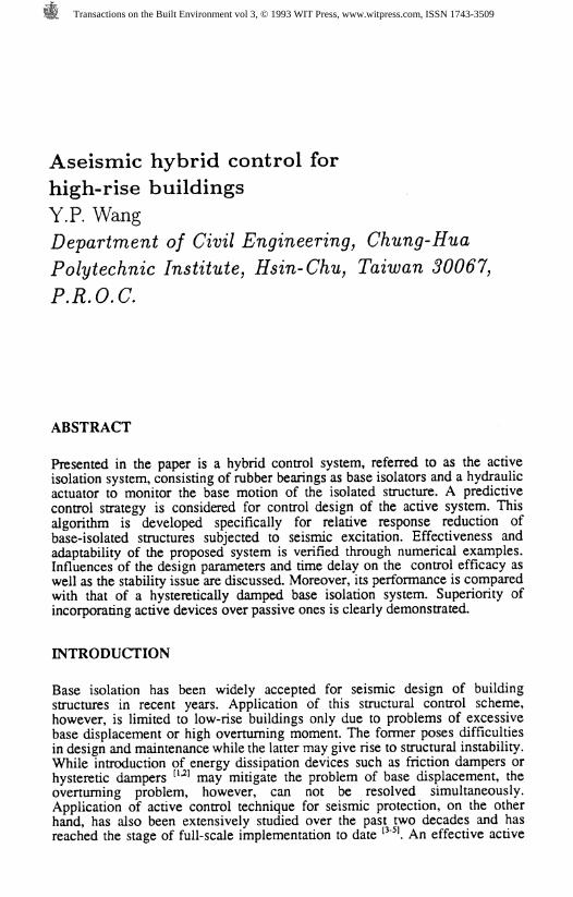
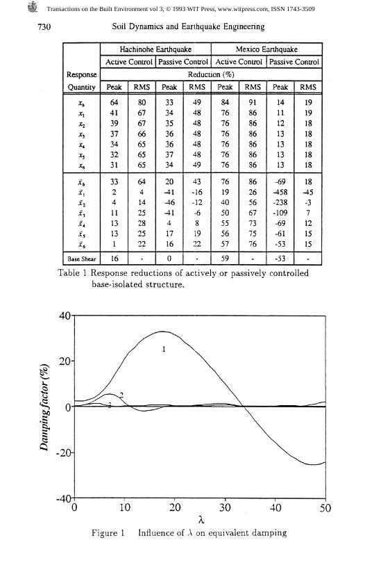
Adopted from a previous study of the author [16], plots of equivalentdamping of the lowest three modes vs. the predicting length X illustrated inFig. 1 show sinusoid-like variations. These curves variate with the samefrequencies as their corresponding modal frequencies. It is interesting to seethat improvement of modal damping is more significant for the first mode thanfor others. In this particular case, damping as high as 30% can be achieved for
Transactions on the Built Environment vol 3, © 1993 WIT Press, www.witpress.com, ISSN 1743-3509
726 Soil Dynamics and Earthquake Engineering
the first mode when X * l/4/;Ar. However,, it could result in negative dampingsif an improper X is used as observed for the first two modes. Therefore, the choiceof a suitable X is crucial in order to facilitate a more efficient control system.
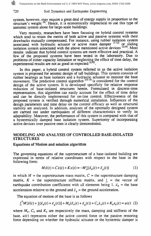
Influences of design parameters Q/R, 5, and X as well as the time delay d onthe control efficiency are analyzed under the excitation of Hachinoheearthquake. Peak responses of the base displacement, the 6th floordisplacement and the base shear are considered as indices for structuralperformance. Furthermore, the maximum control force which serves as anindication of resource demand of the active system is also included. Thesimulated results are summarized in Figures 2(a)-(d). The response quantities(dotted lines) are presented in reduction percentages with respect to theuncontrolled case (refer to the vertical axis on the left) while the maximumcontrol force (solid line) is normalized with respect to the weight of thestructure (refer to the vertical axis on the right).
In Fig. 2(a) the influence of Q/R with 8== 0, X=9 and d= 0 is illustrated. Thecontrol efficiency increases with increasing weighting factor until Q/R=9xlO*.As Q/R keeps increasing, however, no significant improvement is obtained forthe base displacement while amplifications of the 6th floor displacement andthe base shear are induced plus drastically increased control forcerequirements.
In Fig. 2(b) the effect of 8 with Q/R=10*°, X=9 and d=0 is demonstrated.Control efficiencies for the 6th floor displacement and the base shear increasewith 5 increased up to 5 = 0.3 while that of the base displacement decreases.This is reasonable since more weight is given to the superstructure in theobjective function as 5 increases. However, the control system becomes lessefficient when 8 exceeds 0.3.
In Fig. 2(c) the effect of X for Q/R=10'°, 8=0 and d=0 is presented. It is seenfor the considered range of X values that, for the base displacement and thebase shear, the longer the predicting length the better the control efficiencieswhile for the sixth floor displacement this trend is reversed. The requiredcontrol force increases as X increases.
In Fig. 2(d) the influence of time delay is presented. As revealed from theoverall structural response and the control force requirement, the systemperforms less and less efficient as the delay increases although it is stilleffective as compared with the uncontrolled system.
Simulation Results
Performances of the proposed seismic protective systems are evaluated usingthe Hachinohe earthquake and the Mexico earthquake as input excitations. It isnoted that the latter is used intentionally to verify the adequacy of the proposedsystems under resonance conditions. Design parameters considered for theactive control system are Q/R = 9x10*, 8 == 0 and X = 9 with emphasis on basemotion control.
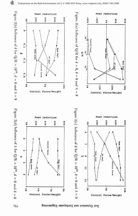
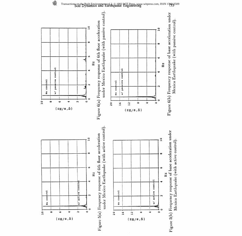
Control efficiences of the systems are presented in terms of peak reductionand root-mean-squared (RMS) reduction of the response quantities assummarized in Table 1. Typical frequency responses of the controlled structureare plotted vs. those of the uncontrolled one in Figures 3 ~ 6. The effectivenessof the active control system is clearly demonstrated. The active system showseven greater improvement under resonance condition, however, it requires also
Transactions on the Built Environment vol 3, © 1993 WIT Press, www.witpress.com, ISSN 1743-3509
Soil Dynamics and Earthquake Engineering 727
greater demand on control resource - the maximum control force required isincreased from 5.5% to 19% of the structure's weight. Time histories of thecontrol force requirement are shown in Figs. 7(a) and 8(a). On the other hand,the passive system though is sufficient for base motion control, it can bringadverse effect on the acceleration responses of the superstructure, especially forthe lower levels. This is a consequence of higher mode amplifications (3rd or4th modes) caused by material nonlinearity of the damper as illustrated in Figs.4 and 6. It is noted that performance of the passive system degrades underresonance condition even though larger restoring force is introduced from thedamper as shown in Figs. 7(b) and 8(b).
CONCLUDING REMARKS
Hybrid control of flexible structures subjected to seismic excitations usingbase isolation system associate with hydraulic actuator (active control) orhysteretic damper (passive control) have been presented. In this study, designof the active controller is based on a predictive control strategy. This algorithmis formulated in discrete-time therefore is suitable for digital control. Specificapplication of this algorithm for active control of base-isolated structures hasbeen demonstrated numerically. A modified version of the Structural StateProcedure (SSP) algorithm is developed for response analyses of linear (withactive control) and nonlinear (with passive control) base-isolated systems.Based on the simulation results, the following conclusions may be drawn:
1. Base isolation system with active control is a feasible solution for seismicdesign of flexible structures. This hybrid system is insensitive to the frequencycontents of the earthquakes, therefore is adequate for applications in varioustypes of seismic areas.
2. As observed from frequency response, the predictive control strategy isextremely efficient for control of the first mode. This is also revealed from theequivalent damping of the feedback controlled system (Fig. 1).
3. The hysteretic damper is useful in base motion control, however, it maycause adverse effect on the acceleration response of the superstructure. Thisdisadvantage may limit its application, especially for buildings housed withsensitive equipment.
4. The superiority of the active control system over the passive one is clearlydemonstrated in this study. It should be pointed out, however, that thehysteretic damper considered in the numerical example has not been optimallydesigned. Nevertheless, the design of active system is more flexible andmanageable in that no modification on the hardwares is necessary.
5.The implementation of this controller requires full state estimation for linearfeedback. Measuring the displacement responses, however, may be a problemin practice since it requires a reference point. Development of an efficientcontrol algorithm with velocity and acceleration feedback of limited sensorsmay be a possible direction.
ACKNOWLEDGEMENTS
The support of this research from the National Science Council of theRepublic of China with contract no. NSC 81-0410-E-216-502 is acknowledged.
Transactions on the Built Environment vol 3, © 1993 WIT Press, www.witpress.com, ISSN 1743-3509
728 Soil Dynamics and Earthquake Engineering
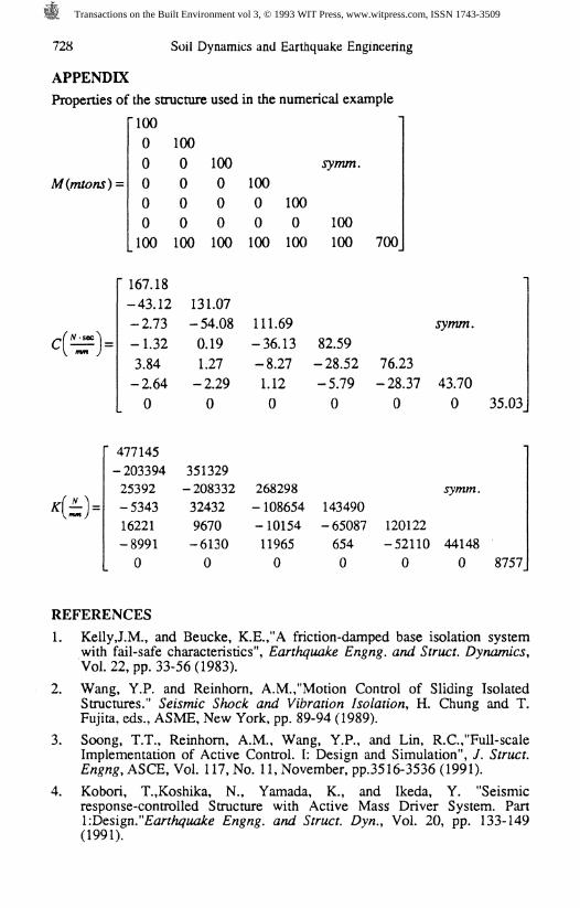
APPENDIX
Properties of the structure used in the numerical example
M(mtons) =
'100
0
0
0
0
0
100
100
0
0
0
0
100
100
0
0
0
100
100
0
0
100
100
0
100
symm.
100
100 700
" 167.18
-43.12
-2.73
-1.32
3.84
-2.64
0
131.07
-54.08
0.19
1.27
-2.29
0
111.69
-36.13
-8.27
1.12
0
82.59
-28.52 76.23
-5.79 -28.37
0 0
symm.
43.70
0 35.03
" 477145-20339425392-534316221-89910
351329-208332324329670-61300
268298-108654 143490-10154 -6508711965 6540 0
symm.
120122-52110 441480 0 8757
REFERENCES
1. KellyJ.M., and Beucke, K.E.,"A friction-damped base isolation systemwith fail-safe characteristics", Earthquake Engng. and Struct. Dynamics,Vol. 22, pp. 33-56(1983).
2. Wang, Y.P. and Reinhorn, A.M.,"Motion Control of Sliding IsolatedStructures." Seismic Shock and Vibration Isolation, H. Chung and T.Fujita, eds., ASME, New York, pp. 89-94 (1989).
3. Soong, T.T., Reinhorn, A.M., Wang, Y.P., and Lin, R.C.,"Full-scaleImplementation of Active Control. I: Design and Simulation", /. Struct.Engng, ASCE, Vol. 117, No. 11, November, pp.3516-3536 (1991).
4. Kobori, T.,Koshika, N., Yamada, K., and Ikeda, Y. "Seismicresponse-controlled Structure with Active Mass Driver System. PartI-.Design."Earthquake Engng. and Struct. Dyn., Vol. 20, pp. 133-149(1991).
Transactions on the Built Environment vol 3, © 1993 WIT Press, www.witpress.com, ISSN 1743-3509
Soil Dynamics and Earthquake Engineering 729
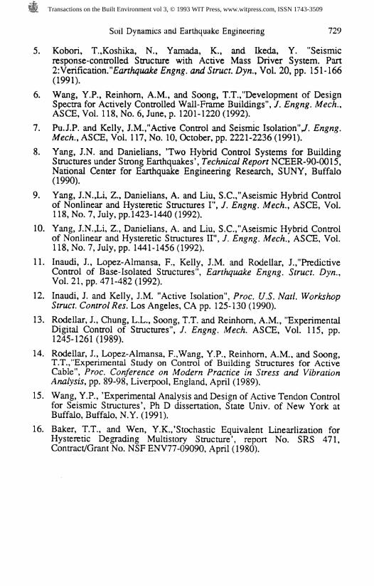
5. Kobori, T.,Koshika, N., Yamada, K., and Ikeda, Y. "Seismicresponse-controlled Structure with Active Mass Driver System. Part2: Verification."Earthquake Engng. and Struct. Dyn., Vol. 20, pp. 151-166(1991).
6. Wang, Y.P., Reinhorn, A.M., and Soong, T.T.,"Development of DesignSpectra for Actively Controlled Wall-Frame Buildings", /. Engng. Mech.,ASCE, Vol. 118, No. 6, June, p. 1201-1220 (1992).
7. PuJ.P. and Kelly, J.M.,"Active Control and Seismic Isolation"/. Engng.Mech., ASCE, Vol. 117, No. 10, October, pp. 2221-2236 (1991).
8. Yang, J.N. and Danielians, Two Hybrid Control Systems for BuildingStructures under Strong Earthquakes', Technical Report NCEER-90-0015,National Center for Earthquake Engineering Research, SUNY, Buffalo(1990).
9. Yang, J.N.JJ, Z., Danielians, A. and Liu, S.C.,"Aseismic Hybrid Controlof Nonlinear and Hysteretic Structures I", /. Engng. Mech., ASCE, Vol.118, No. 7, July, pp. 1423-1440 (1992).
10. Yang, J.N.,Li, Z., Danielians, A. and Liu, S.C.,"Aseismic Hybrid Controlof Nonlinear and Hysteretic Structures II", /. Engng. Mech., ASCE, Vol.118, No. 7, July, pp. 1441-1456 (1992).
11. Inaudi, J., Lopez-Almansa, F., Kelly, J.M. and Rodellar, J.,"PredictiveControl of Base-Isolated Structures", Earthquake Engng. Struct. Dyn.,Vol. 21, pp. 471-482 (1992).
12. Inaudi, J. and Kelly, J.M. "Active Isolation", Proc. U.S. Natl. WorkshopStruct. Control Res. Los Angeles, CA pp. 125-130 (1990).
13. Rpdellar, J., Chung, L.L., Soong, T.T. and Reinhorn, A.M., "ExperimentalDigital Control of Structures", /. Engng. Mech. ASCE, Vol. 115, pp.1245-1261(1989).
14. Rodellar, I, Lopez-Almansa, F.,Wang, Y.P., Reinhorn, A.M., and Soong,T.T.,"Experimental Study on Control of Building Structures for ActiveCable", Proc. Conference on Modern Practice in Stress and VibrationAnalysis, pp. 89-98, Liverpool, England, April (1989).
15. Wang, Y.P., 'Experimental Analysis and Design of Active Tendon Controlfor Seismic Structures', Ph D dissertation, State Univ. of New York atBuffalo, Buffalo, N.Y. (1991).
16. Baker, T.T., and Wen, Y.K./Stochastic Equivalent Linearlization forHysteretic Degrading Multistory Structure', report No. SRS 471,Contract/Grant No. NSF ENV77-09090, April (1980).
Transactions on the Built Environment vol 3, © 1993 WIT Press, www.witpress.com, ISSN 1743-3509
730 Soil Dynamics and Earthquake Engineering
Response
Quantity
J»*i*2*3A*S*6
4*1*2*3*4*S*6
Base Shear
Hachinohe Earthquake
Active Control
Peak
64413937343231
33241113131
16
RMS
80676766656565
6441425282522
Passive Control
Mexico Earthquake
Active Control Passive Control
Reduction (%)
Peak
33343536363734
20-41-46-4141716
0
RMS
49484848484849
43-16-12•681922
-
Peak
84767676767676
76194050555657
59
RMS
91868686868686
86265667737576
-
Peak
14111213131313
-69-458-238-109-69-61-53
-53
RMS
19191818181818
18-45-37121515
-
Table 1 Response reductions of actively or passively controlledbase-isolated structure.
Figure 1 Influence of A on equivalent damping
Transactions on the Built Environment vol 3, © 1993 WIT Press, www.witpress.com, ISSN 1743-3509
Peak reduction Peak reduction
oo
Ci-5/— N
Oo
3C-
Control Force/Weight Control Force/Weight
0to
Peak reductionto
Peak reduction
o3O
£»>-cT
oo
opc-
oo
Control Force/Weight Control Force/Weight
TCZ,
Transactions on the Built Environment vol 3, © 1993 WIT Press, www.witpress.com, ISSN 1743-3509
N33
N33
Cn
i.o
0 .5
8 10
0.5
Figure 3(a) Frequency response of 6th floor acceleration under Figure 4(a) Frequency response of 6th floor acceleration underllachinohe Earthquake (with active control). llachinohe Earthquake (with passive control).
•i . u T i j I 4.0
3.0
2.0
1.0
0.0
Ho cont1
A>
:ol
w / active- control
0 2 4 (Hz
..
) 8 1
3.0N33
2.0-Or.
i.osive cont
C/)C
o
$
m
3era
10Hz
Figure 3(b) Frequency response of base acceleration underllachinohe Earthquake (with active control).
Figure 4(b) Frecjuency response of base acceleration underllachinohe Earthquake (with passive control).
Transactions on the Built Environment vol 3, © 1993 WIT Press, www.witpress.com, ISSN 1743-3509
Soil Dynamics and Earthquake Engineering 733
"o «Ui V
J 8 3 1I 1 1 1 1 r 2 "rt? O o .O •£
O
OUOZ
FH0*Jc0uo>•H«JQ.
^
-<•
J
/1
«- >.2 •«g a* *
li-3. 0Z3 VO O <^<^ 3
N O ?Z o %3W3 U,C (0
* OHIs
&3' <N C ^5
ll0 %& 50
0 CO \0 r* CN 0 (CO' f
(zH/s,6) g
S)£
1ouoz
0cou4)
;
! 1 1D VO (N 00 ««
(2H/s,6)
•<
r <
«H -*-' Q2 wO QJr) • *"J0 w00 ( fj
a § 3C- 3"en —* U *_,
u fc3
1.3
Ui3
2
1OZ
a1
I
o 112 yu >15 V3
oo c\j
II
N *3 cr
"* o yOT* 0U '0
CN U «?H
ll.0 £s- 3
0u0uo
1
r-t
ive contr
u
)-*
.0 1 .
0 1
2 3oo a ^
y |
^ .T>
0 3G. cren —
^ 13
§ 0
0 r^ ZO 00 VO O vo <N 00 T O
(2H/s,6) 100)
o
Transactions on the Built Environment vol 3, © 1993 WIT Press, www.witpress.com, ISSN 1743-3509