Embed Size (px)
Citation preview

10.1098/rspa.2000.0726
Polarization patterns of the summer skyand its neutral points measured by full-sky
imaging polarimetry in Finnish Laplandnorth of the Arctic Circle
By J ¶ozsef G ¶al1, G ¶ab or Horv ¶at h1,Viktor Benno Meyer-Rochow2 a n d R �udiger W ehner3
1Department of Biological Physics, E�otv�os University, H-1117 Budapest,P¶azm¶any s¶et¶any 1, Hungary ([email protected])
2Department of Biology (Zoology), University of Oulu, Linnanmaa A,SF-90401 Oulu, Finland ([email protected]. )
3Zoologisches Institut, Universit�at Z�urich, Winterthurerstrasse 190,CH-8057 Z�urich, Switzerland ([email protected])
Received 6 April 2000; revised 6 November 2000; accepted 30 November 2000
Using 180¯ eld-of-view (full-sky) imaging polarimetry, the patterns of the degreeand angle of polarization of the entire summer sky were measured on 25 June 1999 ata location north of the Arctic Circle in Finnish Lapland as a function of the angularsolar zenith distance. A detailed description of the used full-sky imaging polarimeterand its calibration is given. A series of the degree and angle of polarization patternof the full sky is presented in the form of high-resolution circular maps measured inthe blue (450 nm) spectral range as a function of the solar zenith distance. Graphsof the spectral dependence of the degree and angle of polarization of skylight at 90¯
from the Sun along the antisolar meridian are shown. The celestial regions of negativepolarization and the consequence of the existence of this anomalous polarization, theneutral points, are visualized. The measured values of the angular zenith distanceof the Arago and Babinet neutral points are presented as a function of the zenithdistance of the Sun for the red (650 nm), green (550 nm) and blue (450 nm) rangesof the spectrum. The major aim of this work is to give a clear and comprehensivepicture, with the help of full-sky imaging polarimetry, of what is going on in theentire polarized skydome. We demonstrate how variable the degree of polarization ofskylight and the position of the neutral points can be within 24 h on a sunny, almostcloudless, visually clear day.
Keywords: sky polarization; neutral points; full-sky imaging polarimetry;polarization vision; dispersion of skylight polarization; optical orientation
1. Introduction
The clear sky has a characteristic polarization pattern depending on the angularsolar zenith distance (K�onnen 1985). The polarization of skylight has been the sub-ject of numerous theoretical and experimental investigations (e.g. Chandrasekhar
Proc. R. Soc. Lond. A (2001) 457, 1385{1399
1385
c® 2001 The Royal Society
1386 J. G¶al, G. Horv¶ath, V. B. Meyer-Rochow and R. Wehner
1950; Neuberger 1950; Van de Hulst 1952; Sekera 1957; Holzworth & Rao 1965; Bel-lver 1987; Coulson 1988; North & Duggin 1997; Voss & Liu 1997; Horv´ath et al .1998; Horv´ath & Wehner 1999). Most ground-based measurements of skylight polar-ization were performed by means of point-source polarimeters using narrow-bandinterference lters to determine the degree and angle of polarization for di¬erentwavelengths of light. As these polarimeters possess a very small aperture (ca. 1{5¯,in which the optical information is averaged), the polarization characteristics of thesky can be analysed by them only within very restricted elds of view.
The spatial distribution of the degree and angle of polarization of skylight canbe determined by scanning the rmament with such a point-source polarimeter,but this is a time-consuming task done rarely and only in special cases. Using apoint-source polarimeter and making repeated scans in the Sun’s vertical and alonga meridian crossing the zenith perpendicularly to the solar meridian, Shaw (1975)measured the polarization of skylight in the blue (400 nm) spectral range duringthe total solar eclipse of 30 June 1973 in Kenya. Brines & Gould (1982) undertooksimilar measurements at several points of the rmament by means of a point-sourcescanning polarimeter. They could measure points at every 5¯ of zenith distanceand azimuth of a half hemisphere of the sky within 7{8 min, during which the Sunmoved ca. 2¯ along its arc. Certain unavoidable errors were a consequence of theirrapid measurement process, such as inaccuracies attendant upon setting the axesof the instrument. If one wished to enhance the spatial resolution of the samplesby one or two orders, to obtain a picture-like scan of the polarization of the entiresky, the measurements would require 70{80 or 700{800 min, a period during whichthe celestial polarization pattern would change considerably due to the rotationof the Earth (it takes 80 min for the Sun to move by 20¯). It is clear that thepolarization pattern of the entire rmament cannot reliably be measured by such atime-consuming method. The disadvantage of the very narrow eld of view of point-source polarimeters can be eliminated by wide- eld-of-view imaging polarimetry.
The elds of view of the di¬erent imaging polarimeters designed for di¬erentpurposes by Walraven (1981), Prosch et al . (1983), Egan (1986), Wol¬ (1994),Deschamps et al . (1994), Cronin et al . (1994), Shashar et al . (1995), Horv´ath & Zeil(1996), Horv´ath & Varju (1997), Horv´ath et al . (1997, 1998) or Horv´ath & Wehner(1999), for example, are limited by the eld of view of the (video or photo) cam-era used, being generally no larger than ca. 40{50¯. The entire celestial hemispherecannot be recorded with these polarimeters. Recently, North & Duggin (1997) devel-oped a practical method for obtaining partial Stokes vectors and derivative imagesof the rmament by taking advantage of a four-lens photographic camera. Althoughthe spherical convex mirror of their imaging polarimeter possessed a eld of view ofalmost 180¯, they could not record the entire skydome, because the camera of theirequipment was set up on a huge, heavy tetrapod at a height of 6 m above the mirror.The tetrapod, and also the camera itself, screened out small areas of the rmament.Furthermore, this equipment was rather voluminous and cumbersome, which did notpermit easy and rapid setting up, taking down, transfer and transport. Another,much easier but unportable, design was developed by Voss & Liu (1997) for measur-ing the distribution of polarization in the full sky. The charge-coupled device imagesensor (detector) of this full-sky imaging polarimeter should be thermoelectricallycooled ( ¡ 40 6T 6 ¡ 30 ¯C), and the instrument needs a power supply (220 or110 V) and connection with a computer.
Proc. R. Soc. Lond. A (2001)

Polarization patterns of the full sky and its neutral points 1387
Using 180¯ eld-of-view imaging polarimetry, an opportunity to measure the polar-ization pattern of the entire summer sky occurred for us in Finnish Lapland northof the Arctic Circle. The major motivation of our study was to give a clear and com-prehensive picture of what is going on in the entire polarized skydome. Since full-skyscans of the polarization of skylight have not previously been undertaken, this work lls this gap. In the present work we rst describe in detail our instrument and itscalibration. Then we show a series of the degree and angle of polarization patternsof the full sky in the form of high-resolution circular maps measured in the blue(450 nm) spectral range as a function of the angular solar zenith distance. Graphsof the spectral dependence of the degree and angle of polarization of skylight at 90¯
from the Sun along the antisolar meridian are presented. The celestial regions ofnegative polarization and the consequence of the existence of this anomalous polar-ization, the neutral points, are visualized. The measured values of the angular zenithdistance of the Arago and Babinet neutral points are given as a function of the solarzenith distance for the red (650 nm), green (550 nm) and blue (450 nm) ranges ofthe spectrum. Since at the place and time of our measurements the Sun did not set,we could measure the 24 h change of the polarization pattern of the summer sky. Wedemonstrate here how variable the degree of polarization of skylight and the positionof the neutral points can be within 24 h on a sunny, almost cloudless, visually clearday.
2. Materials and methods
(a) Place and date of the measurements
Our measurements were carried out on a sunny day (25 June 1999) at Sodankyl�aMeteorological Station (67¯250 N, 26¯300 E) of the University of Oulu (Finland) from02:00 on 25 June 1999 to 01:00 on 26 June 1999 (the latter point of time is calledthe `25th hour’ further on in this work). The station is located in the vicinity of thetownship of Sodankyl�a in Finnish Lapland, north of the Arctic Circle. We measuredthe polarization pattern of the entire celestial hemisphere from the top of a 16 mhigh meteorological tower rising above the tips of the surrounding pine trees.
The tower was in the middle of a huge pine forest, the trees of which did not disturbour recordings. The spatial distribution of the albedo of the surrounding terrain (pineforest) was homogeneous, and there was no spatio-temporal variation of the localalbedo during our measurements. Since at the place and time of our measurementsthe Sun did not set, we could make hourly measurements of the changing polarizationpattern of the summer sky throughout the whole day (from 0 to 24 h, local summertime = UTC + 3). During our measuring campaign, the sky was relatively clear foralmost the entire day, but sometimes high altitude thin cirrus clouds occurred nearthe horizon.
(b) Measurement of the celestial polarization pattern byfull-sky imaging polarimetry
The set-up of our full-sky rotating-analyser imaging photopolarimeter is shownin gure 1a. An angle of view of 180¯ is ensured by a Nikon{Nikkor sh-eye lens(F-number = 2:8, focal length = 8 mm), including a built-in rotating disc mountedwith three neutral density linearly polarizing (HNP’B) lters with three di¬erent
Proc. R. Soc. Lond. A (2001)
1388 J. G¶al, G. Horv¶ath, V. B. Meyer-Rochow and R. Wehner
90°
90°
45°
60°
30°
0°30°
top view
0° (measuredfrom the radius)
side view
photoemulsion(roll-film)
zenith of the sky
linearlypolarizing
filters
built-inrotating disc
opticalaxis
photographic camera (Nikon F801)
fish-eye lens (Nikon Nikkor,F = 2.8, focal length = 8 mm)
North
view-finder
camera
N
horizon
W
Santisolarmeridian
solarmeridian
celestial system of polar coordinates
Sun
zenith
E
photoemulsion
projection angle q
60°
p
90°0°
(c)
(d )
f( )
(a)
(b)
(e)
fish-eyelens
fish-eyelens
off-axis angle q
qj
o
q o
0.0
0.0
1.0
1.0-
0.0
1.0
1.0-
0.2
0.4
0.6
hr
0.8
1.0
0°
maximalaperture
effectiveaperture
30°
°Io = I( I()0 ) =
60° 90°
0° 90° 0° 90°
off-axis angle q
q
o
off-axis angle q ooff-axis angle q o
o q o
q o
proj
ecti
on a
ngle
rela
tive
light
inte
nsit
y I
elem
ent m
12 o
f th
ere
duce
d M
uelle
r m
atri
x
elem
ent m
13 o
f th
ere
duce
d M
uelle
r m
atri
x
0 I/q p
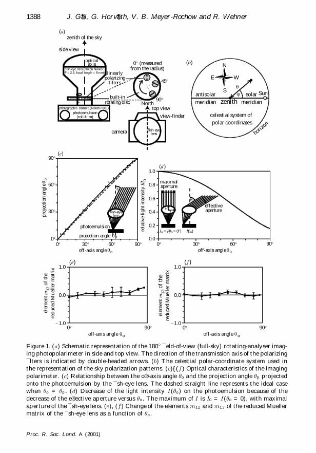
Figure 1. (a) Schematic representation of the 180¯ ¯eld-of-view (full-sky) rotating-analyser imag-ing photopolarimeter in side and top view. The direction of the transmission axis of the polarizing¯lters is indicated by double-headed arrows. (b) The celestial polar-coordinate system used inthe representation of the sky polarization patterns. (c){(f ) Optical characteristics of the imagingpolarimeter. (c) Relationship between the o® -axis angle ³ o and the projection angle ³ p projectedonto the photoemulsion by the ¯sh-eye lens. The dashed straight line represents the ideal casewhen ³ o = ³ p . (d) Decrease of the light intensity I( ³ o ) on the photoemulsion because of thedecrease of the e® ective aperture versus ³ o . The maximum of I is I0 = I( ³ o = 0), with maximalaperture of the ¯sh-eye lens. (e), (f) Change of the elements m12 and m13 of the reduced Muellermatrix of the ¯sh-eye lens as a function of ³ o .
Proc. R. Soc. Lond. A (2001)
Polarization patterns of the full sky and its neutral points 1389
polarization axes (0, 45 and 90¯, measured from the radius of the disc), and thedetector is a photoemulsion in a Nikon F801 photographic camera. For the detector,we used Fujichrome Sensia II 100 ASA colour reversal lm; the maxima and halfband widths of its spectral sensitivity curves were ¶ red = 650 § 30, ¶ green = 550 § 30and ¶ b lu e = 450 § 50 nm.
From a given sky, three photographs were taken for the three di¬erent alignmentsof the transmission axis of the polarizers on the built-in rotating disc. The camerawas set up on a tripod in such a way that its axis passing through the view nderpointed northward and the optical axis of the sh-eye lens was vertical, pointingtowards the zenith ( gure 1a). In order to eliminate distorting internal re®ections ofdirect sunlight from the refracting surfaces of the sh-eye lens, the Sun was screenedout by a small disc, which could be slid along a circular wire positioned radially andconcentrically with respect to the outer (entrance) surface of the lens.
The reliability of the process of development of the colour reversal lms wasensured by always developing the lms in the same professional Kodak photographiclaboratory (in Budapest), using the same automatically controlled method. Withthe aid of a personal computer, after an eight-bit (true-colour) digitization (witha Hewlett Packard ScanJet 6100C with an optical resolution of 600 dpi and anenlargement (or scaling) of 500%) and evaluation of the three developed colour slidesbelonging to a given sky, the patterns of the brightness, degree and angle of polar-ization of skylight were determined and visualized as high-resolution colour-codedtwo-dimensional circular maps in the red (650), green (550) and blue (450 nm) spec-tral ranges, in which the three colour-sensitive layers of the used photoemulsion havethe maximal sensitivity. The red, green and blue spectral ranges were obtained usinga digital image processing program provided with the scanner to digitally separatethe colour channels in the digitized images. The calculation of the brightness, degreeand angle of polarization of skylight was the same as in the case of videopolarimetry(Horv´ath & Varju 1997). The three-dimensional celestial hemisphere was representedin two dimensions by a polar-coordinate system, where the angular distance ³ fromthe zenith and the azimuth angle ’ from the solar meridian are measured radiallyand tangentially, respectively ( gure 1b). In this two-dimensional coordinate system,the zenith corresponds to the centre and the horizon to the perimeter of the circularmap.
(c) Algorithmic determination of the zenith distance ofthe Arago and Babinet neutral points
In the red, green and blue spectral ranges, the zenith distances of the Arago andBabinet neutral points were determined by a simple algorithm, which took intoconsideration that (i) the skylight is unpolarized ( ¯ = 0%) in a neutral point; (ii) thedegree of polarization gradually increases with increasing angular distance from aneutral point; and (iii) the skylight polarization switches from negative to positive(that is, the angle of polarization ¬ su¬ers a change of j¢ ¬ j = 90¯) as one passesa neutral point parallel to the solar or antisolar meridian. The points possessingthese characteristics were recognized in a given sky (around the tips of the eight-shaped blue-green celestial region of the ¬ -pattern with positive polarization seenin gure 2a). Then the position of the Arago or Babinet point was obtained as thegeometric centre (centre of mass) of these points. In certain cases, the deviation of
Proc. R. Soc. Lond. A (2001)
1390 J. G¶al, G. Horv¶ath, V. B. Meyer-Rochow and R. Wehner
angle ofpolarization
a
angle ofmeasured from the
local meridian
polarization a
colourphotograph
degree ofpolarization
d
degree ofpolarization
d
angle ofpolarization
a
colourphotograph
degree ofpolarization
d
N
S
W
0%
100%
0°
180°
90°- 90°
- 45° 45°
- 135° 135°E
(a)
2 h = 83.1° s q
3 h = 82.5° s q
4 h = 81.0° s q
5 h = 78.5° s q
6 h = 75.4° s q
8 h = 64.4° s q
9 h = 60.1° s q
10 h = 56.0°s q
11 h = 52.0° s q
13 h = 47.5° s q
7 h = 68.0° s q
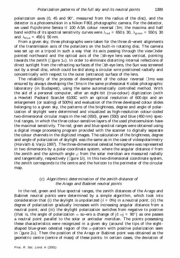
Figure 2. (a) The colour photograph and the degree ¯ and angle ¬ of polarization pattern of theentire celestial hemisphere versus the time (and the angular solar zenith distance ³ s ) measuredby full-sky imaging polarimetry in the blue (450 nm) spectral region from 2 h (local summertime = UTC + 3, ³ s = 83:1¯) to 13 h ( ³ s = 47:5¯) on 25 June 1999 in Sodankyl�a (67¯250 N,26¯300 E, Finnish Lapland). In the black celestial regions of the ¬ -pattern, the photoemulsion wasover-exposed. The two radial bars in the circular pictures come from a wire (holding a small discto screen out the Sun) and a pole (pointing approximately north-eastward and accommodatingan anemometer) on the top of the meteorological tower where the measurement was performed.The position of the Sun is indicated by the small screening disc.
these points from each other was so great that the Arago and/or the Babinet neutralpoint could not have been algorithmically recognized. This is the reason why thepositions of the Arago and Babinet points could not always have been evaluatedfrom the measured celestial polarization patterns ( gure 3).
(d ) Instrument calibration
The calibration of our instrument involved the determination of the in®uence ofthe sh-eye objective on the optical parameters of the light passing through it, andthe determination of the transfer function of the whole evaluation process; that is,the function between the real intensity I of the light fallen onto the photoemulsionand the digital value DV of the brightness taken from the digitization process.
Proc. R. Soc. Lond. A (2001)
Polarization patterns of the full sky and its neutral points 1391
angl
e of
pol
ariz
atio
n
at 9
0° f
rom
the
sun
alon
gth
e an
tisol
ar m
erid
ian a
180°
0°degr
ee o
f po
lari
zatio
n
at 9
0° f
rom
the
sun
alon
gth
e an
tiso
lar
mer
idia
n d
100%(b) (c)
0%45°
angular solar zenith distance85°
2
4
5671112
14 19 20 21181716
2413
25
102
4567
11
12
14
1920 21
181716
24
13
25
10
q s
45°angular solar zenith distance
85°q s
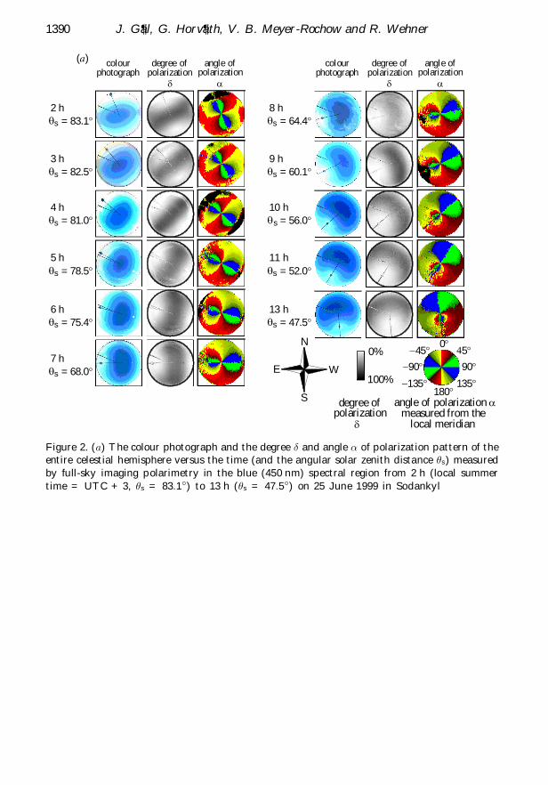
Figure 2. (Cont.) (b), (c) Spectral dependence of the degree ¯ and angle ¬ of polarization ofskylight measured in the blue (450), green (550) and red (650 nm) spectral ranges at 90¯ fromthe Sun (averaged on a small circular celestial region with a radius of ten pixels; the radiusof the entire sky was 334 pixels) along the antisolar meridian versus the angular solar zenithdistance ³ s . The numbers around the graphs indicate the hours (UTC + 3) of recording. In the¯rst and second half of the course, the neighbouring points of the graphs are connected withsolid and broken straight lines (linear interpolation), respectively.
(i) Calibration of the ¯sh-eye objective
Our 180¯ eld-of-view sh-eye objective forms a circular image with a radius ofR = 10 mm in its focal plane (on the photoemulsion) from the object eld. Theincident rays originating from a given o¬-axis angle ³ o are focused into a given pointof this circular image at a distance r from the centre. The value of the so-called`projection angle’ was calculated as ³ p = 90¯r=R. In order to determine the angulartransfer function ³ o( ³ p ) of the camera- sh-eye lens system, we took pictures from anarc composed of a black and white grating with a frequency of 5¯ in its centre withthe sh-eye lens and the camera. The measured inverse angular transfer function³ p ( ³ o) is shown in gure 1c. The polynomial tted to the measured values of ³ o( ³ p )is
³ o =
7
i= 1
ai³ p
90¯
i
90¯;
a1 = 0:977 552; a2 = ¡ 0:862 213; a3 = 5:405 678;
a4 = ¡ 16:3937; a5 = 26:219 318; a6 = ¡ 20:857 125;
a7 = 6:510 49; 0 6³ p 690¯; ³ o = ³ o( ³ p ):
(2.1)
The light intensity I reaching the photoemulsion decreases because of the decreasein the e¬ective aperture as the o¬-axis angle ³ o increases. The change of the relativelight intensity I=I0 versus ³ o is as follows ( gure 1d):
I( ³ o)
I( ³ o = 0)² I
I0
= cos ³ o if ³ o 6arctan» ¡ h
r;
I
I0
=1
2rr cos ³ o +
r2 + h2
2h(1 ¡ sin ³ o) + h sin ³ o
if ³ o > arctan» ¡ h
r;
(2.2)
Proc. R. Soc. Lond. A (2001)
1392 J. G¶al, G. Horv¶ath, V. B. Meyer-Rochow and R. Wehner
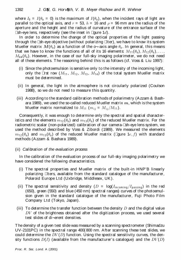
where I0 = I( ³ o = 0) is the maximum of I(³ o), when the incident rays of light areparallel to the optical axis, and r = 53, h = 16 and » = 96 mm are the radius of theaperture and the height and the radius of curvature of the entrance surface of the sh-eye lens, respectively (see the inset in gure 1d).
In order to determine the change of the optical properties of the light passingthrough the sh-eye objective (without polarizing lter), we have to know its systemMueller matrix M( ³ o) as a function of the o¬-axis angle ³ o. In general, this meansthat we have to know the functions of all of its 16 elements: M11( ³ o); M12( ³ o); : : : ;M44( ³ o). However, in the case of our full-sky imaging polarimeter, we do not needall of these elements. The reasoning behind this is as follows (cf. Voss & Liu 1997):
(i) Since the photoemulsion is sensitive only to the intensity of the incoming light,only the rst row (M11, M12, M13, M14) of the total system Mueller matrixmust be determined.
(ii) In general, the light in the atmosphere is not circularly polarized (Coulson1988), so we do not need to measure this quantity.
(iii) According to the standard calibration methods of polarimetry (Azzam & Bash-ara 1989), we used the so-called reduced Mueller matrix m, which is the systemMueller matrix normalized to M11 (mij = Mij=M11).
Consequently, it was enough to determine only the spectral and spatial character-istics and the elements m12( ³ o) and m13( ³ o) of the reduced Mueller matrix. For theradiometric scalar (non-polarized) calibration of our camera- sh-eye lens system, weused the method described by Voss & Zibordi (1989). We measured the elementsm12( ³ o) and m13( ³ o) of the reduced Mueller matrix ( gure 1e; f) with standardmethods (Azzam & Bashara 1989).
(ii) Calibration of the evaluation process
In the calibration of the evaluation process of our full-sky imaging polarimetry wehave considered the following characteristics.
(i) The spectral properties and Mueller matrix of the built-in HNP’B linearlypolarizing lters, available from the standard catalogue of the manufacturer,Polaroid Europe Ltd (Uxbridge, Middlesex, UK).
(ii) The spectral sensitivity and density (D = log(Iin com in g=I p as s in g) in the red(650), green (550) and blue (450 nm) spectral ranges) curves of the photoemul-sion given in the standard catalogue of the manufacturer, Fuji Photo FilmCompany Ltd (Tokyo, Japan).
(iii) To determine the transfer function between the density D and the digital valueDV of the brightness obtained after the digitization process, we used severaltest slides of di¬erent densities.
The density of a given test slide was measured by a scanning spectrometer (ShimadzuUV-2101PC) in the spectral range 400{800 nm. After scanning these test slides, wecould determine the DV (D) function. Using the spectral sensitivity curves, the den-sity functions D(I) (available from the manufacturer’s catalogue) and the DV (D)
Proc. R. Soc. Lond. A (2001)

Polarization patterns of the full sky and its neutral points 1393
functions (in the red, green and blue channels), we could determine the DV (I) func-tions (depending on the type of the photoemulsion used as detector). From theinverse I(DV ) function, we could calculate the real intensity of light I (measured inlux seconds (lx s)).
3. Results
Figure 2a shows a series of the colour photographs and the degree ¯ and angle¬ of polarization patterns of the entire celestial hemisphere as a function of theangular solar zenith distance ³ s measured by full-sky imaging polarimetry in the blue(450 nm) spectral range from ³ s = 83:1 to ³ s = 47:5¯ on 25 June 1999 in Sodankyl�a(67¯250 N, 26¯300 E, Finnish Lapland). Because of the qualitative resemblance ofthe full-sky polarization patterns measured in di¬erent spectral ranges, we omit thepatterns measured in the red and green ranges.
In gure 2a we can see, for example, that the degree of skylight polarization rstincreases with increasing angular distance from the Sun, reaching its maximum,the value of which depends on the Sun’s zenith distance and on the meteorologicalconditions (on haze and the aerosol concentration), at ca. 90¯ from the Sun, and thendecreasing towards the anti-Sun. The ¯ -pattern at 8 h demonstrates how the degreeof polarization of skylight was reduced by the thin cirrus clouds near the horizon.Figure 2a demonstrates well the characteristic axial symmetry of the sky polarizationpattern too, and that the axis of symmetry is the solar and antisolar meridian.
Parts (b) and (c) of gure 2 show the spectral dependence of the degree ¯ and angle¬ of polarization of skylight measured in the blue (450), green (550) and red (650 nm)spectral ranges at 90¯ from the Sun along the antisolar meridian as a function of theangular solar zenith distance. Sky polarization is frequently measured in this celestialdirection, where ¯ is maximal ³ if the sky is clear. We can see from gure 2b that,during the 24 h period investigated (from 2 to 24 + 1 h), at 90¯ from the Sun alongthe antisolar meridian, the degree of polarization of skylight was always lowest in thered spectral range (25 6 red 657% for solar zenith distances of 47:5 6³ s 683:1¯).For certain solar zenith distances, the ¯ values were higher in the blue spectral rangethan those in the green range, while for other solar zenith distances the relationwas the contrary. Although the temporal change of the degree of polarization ¯ wasnot monotonous in all three spectral ranges, there was a general trend that, at 90¯
from the Sun, ¯ decreased with decreasing solar zenith distance, especially in the redregion of the spectrum. During the 24 h studied, there was a characteristic hysteresisin the temporal change of the degree of polarization: when the Sun moved alongthe rst half of its arc, from 2 to 13 h, the change of ¯ in all three spectral rangeswas characterized by di¬erent graphs in comparison with the case between 14 and24 + 1(= 25) h.
We can see in gure 2c that, during the 24 h period studied, at 90¯ from theSun along the antisolar meridian, independently of the wavelength, the angle ofpolarization was always within the range 80 < ¬ < 100¯, with an average of 90 § 10¯;that is, the direction of polarization was always approximately perpendicular to theantisolar meridian, as expected from Rayleigh theory. The di¬erence between the ¬values at a given time was maximal for the red and blue range of the spectrum andit was always smaller than ca. 10¯. There was not any systematic temporal changeof the angle of polarization.
Proc. R. Soc. Lond. A (2001)
1394 J. G¶al, G. Horv¶ath, V. B. Meyer-Rochow and R. Wehner
horizon
Brewster
Arago
Babinet
zenith
Sun
D. F. J. Arago(1786–1853)
25 h 24 h 23 h
22 h
21 h
20 h
19 h
18 h
17 h
16 h
15 h
14 h
13 h12 h11 h
10 h
9 h
8 h
7 h
6 h
5 h
4 h
3 h
2 h
12:39 D. Brewster(1781–1868)
W
N
E
S
Aragoneutralpoint
Babinet neutral point
degree ofpolarization d
0%
100%
J. Babinet(1794–1872)
90°
55°50°
17
angu
lar
zeni
th d
ista
nce
ofth
e A
rago
neu
tral
poi
nt
85°
Arago neutral point
2
45
67
9
1011 18
19 20
2122
2325
(b)
(a)
(c)60°
25°
angu
lar
zeni
th d
ista
nce
ofth
e B
abin
et n
eutr
al p
oint
45° 85°12:39’
Babinet neutral point
23
67
89
11
1213
1819
20212223
14
25
17
angular solar zenith distance q s angular solar zenith distance q s
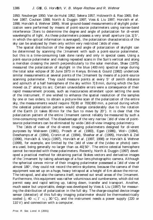
Figure 3. For description see opposite.
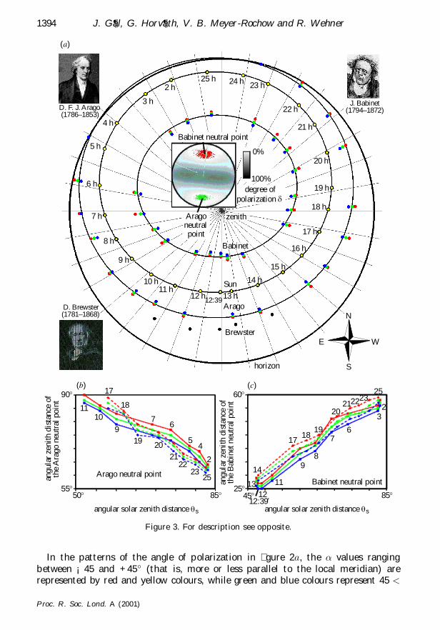
In the patterns of the angle of polarization in gure 2a, the ¬ values rangingbetween ¡ 45 and +45¯ (that is, more or less parallel to the local meridian) arerepresented by red and yellow colours, while green and blue colours represent 45 <
Proc. R. Soc. Lond. A (2001)

Polarization patterns of the full sky and its neutral points 1395
¬ < 135¯ (that is, more or less perpendicular to the local meridian). We can seethat, in the case of this colour coding of the angle of polarization, an eight-shapedblue{green region occurs around the zenith in the dominating yellow{red area ofthe sky. The bright yellow{red zones around the tips of this eight-shaped blue{greenregion are the areas of the so-called `anomalous’ or `negative’ polarization of skylight.The polarization along the solar and antisolar meridian within this blue{green eight-shaped celestial region is called `normal’ or `positive’. Figure 2a demonstrates wellhow the celestial areas of positive and negative polarization change as a function ofthe solar zenith distance.
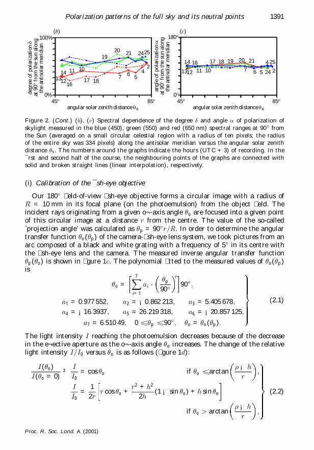
The consequence of the negative polarization of skylight is the existence of theunpolarized or neutral points. The Arago and Babinet neutral points are positionedalways at the tips of the eight-shaped blue{green region of the angle of polariza-tion maps in gure 2a, where positive polarization switches to negative polarization.Figure 3a represents the hourly positions of the Arago and Babinet neutral pointsof skylight polarization on the rmament evaluated from a 24 h series of the celes-tial polarization patterns measured by full-sky imaging polarimetry on 25 June 1999in Sodankyl�a in the red (650), green (550) and blue (450 nm) spectral ranges. Thepositions of the Brewster neutral point could not have been evaluated due to theover-exposure of the photoemulsion in the vicinity of the Sun. Usually, the Brewsterpoint is positioned on the solar meridian below the Sun at about the same angulardistance as the Babinet point above the Sun (Coulson 1988; Horv´ath et al . 1998).The positions of the Brewster neutral point (indicated by black dots in gure 3a)were predicted on the basis of this rule.
The inset in the middle of gure 3a shows the pattern of the degrees of polarization¯ for a solar zenith distance of ³ s = 81:2¯ measured at 24 h (UTC+3) on 25 June 1999in Sodankyl�a. The Arago and Babinet neutral points and their immediate vicinitiesare shaded with green and red colours, respectively, indicating ¯ 62%. Parts (b) and(c) of gure 3 represent the change of the zenith distance of the Arago and Babinetneutral points for the red, green and blue spectral ranges as a function of the solarzenith distance. The most important characteristics of the Arago and Babinet pointsread from gure 3 are the following.
Figure 3. (a) Hourly positions of the Sun and Arago, Babinet and Brewster neutral points of skylightpolarization on the rmament evaluated from a 24 h series of the celestial polarization patterns measuredby full-sky imaging polarimetry on 25 June 1999 in Sodankyl�a. The positions of the Sun are indicated byyellow dots, and next to them the times of recording are shown. The positions of the Arago and Babinetneutral points measured in the red (650), green (550) and blue (450 nm) spectral regions are indicatedby red, green and blue dots, respectively. At a given position of the Sun, the Babinet point is placedon the solar meridian, while the Arago point is placed on the antisolar meridian. Black dots representthe predicted positions of the Brewster neutral point. For a few hours, the positions of the Arago andBabinet points could not be evaluated from the recordings. The ellipses represent the trajectories of theSun and the Arago and Babinet points tted to their hourly measured positions by the method of leastsquares. The insets in the corners show the portraits of Arago, Babinet and Brewster, who discovered theneutral points of the polarized rmament in 1810, 1840 and 1842, respectively. The inset in the middleshows the pattern of the degree of polarization ¯ of the full sky for an angular solar zenith distance of³ s = 81:2¯, measured at 24 h on 25 June 1999 in Sodankyl�a, where the Arago and Babinet neutral pointsand their immediate vicinities are shaded with green and red colours, respectively, indicating ¯ 62%.(b), (c) The change of the angular zenith distance of the Arago and Babinet neutral points for the red,green and blue spectral ranges as a function of the angular solar zenith distance. The numbers aroundthe graphs indicate the hours (local summer time, UTC + 3) of recording. In the rst and second halfof the course, the neighbouring points of the graphs are connected with solid and broken straight lines(linear interpolation), respectively.
Proc. R. Soc. Lond. A (2001)
1396 J. G¶al, G. Horv¶ath, V. B. Meyer-Rochow and R. Wehner
(i) The smaller the solar zenith distance, the smaller or the larger is the zenithdistance of the Babinet or Arago point, respectively.
(ii) The longer the wavelength of skylight, the larger is the zenith distance of theArago and Babinet points.
Similarly to the temporal change of the degree of polarization of skylight at 90¯
from the Sun, during the 24 h studied, there was a hysteresis in the temporal changeof the zenith distance of the Arago and Babinet points, as can be seen in gure 3b; c.When the Sun moved along the rst half of its arc in the sky (from 2 to 11 h for theArago point, and from 2 to 13 h for the Babinet point), the change of the zenith dis-tance of the neutral points in all three spectral ranges was characterized by di¬erentgraphs, in comparison with the case when the Sun moved along the second half of itsarc (from 17 to 25 h for the Arago point, and from 14 to 25 h for the Babinet point).
4. Discussion
In our full-sky imaging polarimetric method, we used a normal photographic camerawith roll- lms. For this purpose, one can also use a digital camera with an appropri-ate sh-eye lens with a 180¯ eld of view. The use of a photoemulsion in a normalcamera and a digitizing system (e.g. a scanner) with a high optical resolution has theadvantage that, at least presently, a much greater spatial resolution can be achievedthan in the case of a digital camera. Furthermore, for eld work, conventional photo-graphic cameras are more advantageous than digital cameras, which are very sensitiveto environmental variations, such as dust, direct sunshine, or changes in air temper-ature, air humidity or electromagnetic elds, for example. Digital cameras also needexpensive electromagnetic storage media, or a connection to a portable computer, inorder to store the digital recordings. The latter method of information storage is notideal for eld work. These problems are simply eliminated if one uses a normal andless sensitive photographic camera with as many roll- lms as needed in the eld.
Figures 2b and 3 demonstrate that the degree of polarization of skylight and thezenith distance of the neutral points of skylight polarization can change considerablywithin hours even if the sky is relatively visually clear throughout the day (24 h).The rather unsettled temporal variation of the degree of polarization of the clearsky and the hysteresis of this variation seen in gure 2b and gure 3b; c, show thatthe degree of polarization pattern of a clear sky is temporally unstable (that is,for the same solar zenith distance at di¬erent times, signi cantly di¬erent ¯ valuescan occur in a given point of a clear sky), in comparison with the relatively stablepattern of the angle of polarization (that is, the ¬ values in a given point of a clearsky are approximately the same at di¬erent times if the solar zenith distance is thesame). This problem, and the temporal stability of the ¬ -pattern of a cloudy sky, arestudied and discussed elsewhere (Pomozi et al . 2001). Thus it is not surprising thatpolarization-sensitive animals that orient or navigate with the aid of the celestialpolarization use the angle of polarization pattern of the sky and not the degree ofpolarization pattern (Wehner 1976, 1997; Brines & Gould 1982).
The most anomalous feature for gure 2b is the low magnitude of the degree ofpolarization in the red (650 nm) spectral range. This corresponds to that measuredby Coulson (1988, pp. 308{312) at Davis (CA, USA), under conditions of moderatehaze on 25 July 1973, for instance. The surface albedo of the area surrounding Davis
Proc. R. Soc. Lond. A (2001)

Polarization patterns of the full sky and its neutral points 1397
is typical of that of green vegetation, with some elds of bare loam-type soil, like thearea surrounding Sodankyl�a, the place of our imaging polarimetric measurements. Adecrease in the degree of polarization of skylight at the longer wavelengths is typicalof hazy conditions, and the relatively high albedo of vegetated surfaces (pine forestin Sodankyl�a) in the longer wavelength range is an additional contributing factor.Generally, the turbidity (e.g. haze or dust) of the atmosphere strongly reduces themaximum of the degree of polarization, particularly at longer wavelengths (Coulson1988, p. 289). This may also explain why northern Finnish bumblebees exhibit high-est polarization sensitivity in the blue-sensitivity photoreceptor cells (Meyer-Rochow1981).
Using a point-source polarimeter, Beaglehole & Carter (1992) measured the sky-light polarization in the Sun-zenith plane in a high-albedo environment in the Antarc-tic during spring. They experienced that the skylight in Antarctica had a low max-imum polarization of ca. 40%, essentially independent of wavelength across the vis-ible spectrum due to multiple scattering in the atmosphere induced by the highsnow albedo. Contrary to these ndings, at Sodankyl�a we observed a greater spec-tral variation of the degree of polarization ¯ of skylight and higher maxima of ¯ranging from 25 to 72% ( gure 2b). The zenith distance of the Arago and Babinetneutral points also depended on the wavelength ( gure 3). These observations canbe explained by the fact that our measurements were performed in summer in a pineforest and not in a snowy high-albedo environment. Thus the spectral characteristicsof the sky polarization in Sodankyl�a were in®uenced less by the multiple scatteringin the atmosphere induced by light re®ected from the woody terrain.
For a neutral point to occur in the sky, the positively polarized skylight intensity(the Stokes parameter Q if U = 0), in which the direction of polarization is normal tothe plane of scattering passing through the observer, the Sun and the point observed,should be cancelled out by the negatively polarized skylight intensity, in which thedirection of polarization is parallel to the scattering plane. Multiple scattering of lightenhances the negatively polarized intensity (Chandrasekhar 1950). The stronger themultiple scattering, the greater the negatively polarized intensity that appears in theatmosphere, and the more the neutral points are displaced from the Sun or anti-Sun.The amount of multiple scattering is strongly a¬ected by atmospheric turbidity.
The di¬erent positions of the neutral points in the red, green and blue regionsof the spectrum seen in gure 3 demonstrate well the dispersion of skylight polar-ization and are in accordance with earlier measurements (Coulson 1988; Horv´athet al . 1998). K�onnen (1985), in his popular book about polarized light in nature,and Coulson (1988), in his famous monograph on polarization and intensity of lightin the atmosphere, summarized information on skylight polarization put togetherduring the last two centuries. These studies are now complemented by the directmeasurements and the visualization of the polarization patterns of the entire celes-tial hemisphere with the aid of full-sky imaging polarimetry. The advantage of thisapproach lies in the ability to image the polarization of the entire sky, and to producehigh-resolution colour-coded circular maps of the degree and angle of polarizationof skylight. Finally, we would like to mention that using an appropriate waterproofhousing, 180¯ eld-of-view imaging polarimetry can also be used underwater to mea-sure the extended polarization patterns of aquatic optical environments.
This work was supported by a three-year J¶anos Bolyai postdoctoral research fellowship receivedby G.H. from the Hungarian Academy of Sciences, and by a one-year doctoral research fel-
Proc. R. Soc. Lond. A (2001)

1398 J. G¶al, G. Horv¶ath, V. B. Meyer-Rochow and R. Wehner
lowship received by J.G. from the George Soros Foundation (grant number 230/2/878). Thegrants OTKA T-034981 received by G.H. from the Hungarian National Science Foundationand 31-43317.95 received by R.W. from the Swiss National Science Foundation are gratefullyacknowledged. Further ¯nancial support came from the Oulu University and Nowotka Metall-bau K G, Bremen (V.B.M.-R.). Many thanks are due to Professor Jorma Kangas (Sodankyl�aGeophysical Observatory), who organized our accommodation at the Meteorological Station inSodankyl�a. We are grateful to two anonymous referees for their valuable comments.
References
Azzam, R. M. A. & Bashara, N. M. 1989 Ellipsometry and polarized light. Amsterdam: North-Holland.
Beaglehole, D. & Carter, G. G. 1992 Antarctic skies. 2. Characterization of the intensity andpolarization of skylight in a high albedo environment. J. Geophys. Res. 97, 2597{2600.
Bellver, C. 1987 In° uence of particulate pollution on the positions of neutral points in the skyat Seville (Spain). Atmos. Environ. 21, 699{702.
Brines, M. L. & Gould, J. L. 1982 Skylight polarization patterns and animal orientation. J. Exp.Biol. 96, 69{91.
Chandrasekhar, S. 1950 Radiative transfer. Oxford: Clarendon.
Coulson, K. L. 1988 Polarization and intensity of light in the atmosphere. Hampton, VA:A. Deepak.
Cronin, T. W., Shashar, N. & Wol® , L. B. 1994 Portable imaging polarimeters. In Proc. 12thIAPR Int. Conf. on Pattern Recognition, Jerusalem, Israel, 9{13 October 1994, pp. 606{609.
Deschamps, P. Y., Br¶eon, F. M., Leroy, M., Podaire, A., Bricaud, A., Buriez, J. C. & S¶eze, G.1994 The POLDER mission: instrument characteristics and scienti¯c objectives. IEEE Trans.Geosci. Remote Sensing 32, 598{615.
Egan, W. G. 1986 Proposed design of an imaging spectropolarimeter/photometer for remotesensing of earth resources. Opt. Engng 25, 1155{1159.
Holzworth, G. C. & Rao, C. R. 1965 Studies of skylight polarization. J. Opt. Soc. Am. 55,403{408.
Horv¶ath, G. & Varj¶u, D. 1997 Polarization pattern of freshwater habitats recorded by videopolarimetry in red, green and blue spectral ranges and its relevance for water detection byaquatic insects. J. Exp. Biol. 200, 1155{1163.
Horv¶ath, G. & Wehner, R. 1999 Skylight polarization as perceived by desert ants and measuredby video polarimetry. J. Comp. Physiol. A 184, 1{7.
Horv¶ath, G. & Zeil, J. 1996 Kuwait oil lakes as insect traps. Nature 379, 303{304.
Horv¶ath, G., G¶al, J. & Wehner, R. 1997 Why are water-seeking insects not attracted by mirages?The polarization pattern of mirages. Naturwissenschaften 84, 300{303.
Horv¶ath, G., G¶al, J., Pomozi, I. & Wehner, R. 1998 Polarization portrait of the Arago point:video-polarimetric imaging of the neutral points of skylight polarization. Naturwissenschaften85, 333{339.
K�onnen, G. P. 1985 Polarized light in nature. Cambridge University Press.
Meyer-Rochow, V. B. 1981 Electrophysiology and histology of eye of the bumblebee Bombushortorum (Hymenoptera: Apiolae). J. R. Soc. NZ 11, 123{153.
Neuberger, H. 1950 Arago’s neutral point: a neglected tool in meteorological research. Bull. Am.Meteorol. Soc. 31, 119{125.
North, J. A. & Duggin, M. J. 1997 Stokes vector imaging of the polarized sky-dome. Appl. Opt.36, 723{730.
Pomozi, I., Horv¶ath, G. & Wehner, R. 2001 How the clear-sky angle of polarization patterncontinues underneath clouds: full-sky measurements and implications for animal orientation.J. Exp. Biol. (In the press.)
Proc. R. Soc. Lond. A (2001)

Polarization patterns of the full sky and its neutral points 1399
Prosch, T., Hennings, D. & Raschke, E. 1983 Video polarimetry: a new imaging technique inatmospheric science. Appl. Opt. 22, 1360{1363.
Sekera, Z. 1957 Light scattering in the atmosphere and the polarization of skylight. J. Opt. Soc.Am. 47, 484{490.
Shashar, N., Cronin, T. W., Johnson, G. & Wol® , L. B. 1995 Portable imaging polarized lightanalyzer. Proc. SPIE 2426, 28{35.
Shaw, G. E. 1975 Sky brightness and polarization during the 1973 African eclipse. Appl. Opt.14, 388{394.
Van de Hulst, H. C. 1952 Scattering in atmospheres. In The atmosphere of the earth and planets(ed. G. P. Kniper). University of Chicago Press.
Voss, K. J. & Liu, Y. 1997 Polarized radiance distribution measurements of skylight. I. Systemdescription and characterization. Appl. Opt. 36, 6083{6094.
Voss, K. J. & Zibordi, G. 1989 Radiometric and geometric calibration of a visible spectralelectro-optic ` sh-eye’ camera radiance distribution system. J. Atmos. Oceanic Technol. 6,652{662.
Walraven, R. L. 1981 Polarization imagery. Opt. Engng 20, 14{18.
Wehner, R. 1976 Polarized-light navigation by insects. Scient. Am. 235(1), 106{114.
Wehner, R. 1997 The ant’s celestial compass system: spectral and polarization channels. In Ori-entation and communication in arthropods (ed. M. Lehrer), pp. 145{185. Basel: Birkh�auser.
Wol® , L. B. 1994 Polarization camera for computer vision with a beam splitter. J. Opt. Soc.Am. A 11, 2935{2945.
Proc. R. Soc. Lond. A (2001)