Embed Size (px)
Citation preview
RELAYS
Presented By:-ANIL KUMAR KUMAWAT 4Yr. EE
Guided By:-Mr. GAURAV SRIVASTAVA(Seminar Co-ordinator)
CONTENTS :-Introduction
trip circuit
Functional diagram
Classifications
Distance relAy
I. Impedance relay
II. Reactance relay
III. Mho relay
references
Introduction :-
designed to trip a circuit breaker when a fault is
detected.
A relay may also be called an “electromagnetic
switch”.
Relays use a “low amperage circuit” to control a
“high amperage circuit”.
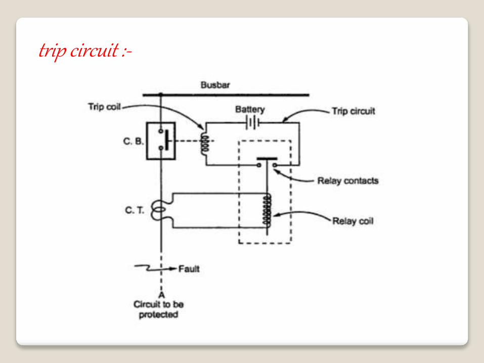
trip circuit :-
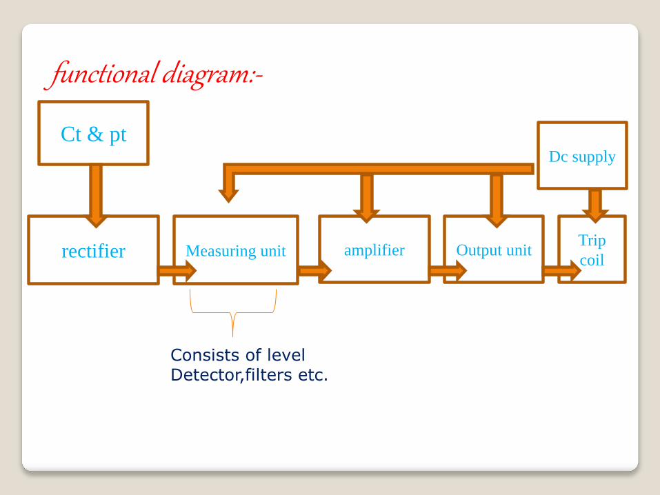
functional diagram:-
Ct & pt
rectifier Measuring unit amplifier Output unitTrip
coil
Dc supply
Consists of level Detector,filters etc.
Classifications :-
According to Construction & Principle –
1. Electromagnetic Attraction relay
2. Electromagnetic Induction relay
3. Electro dynamic relay
4. Moving Coil relay
5. Thermal type relay
6. Static relay etc.
According to Applications :-
1.Under V,Under I,Under P Relay
2.Over V, Over I,Over P Relay
3.Directional or Reverse Current Relay
4.Directional or Reverse Power Relay
5.Differential Relay
6.Distance Relay etc.
According to Time of Operation :-
1.Instantaneous type Relay
2.Definite Time Lag Relay
3.Inverse Time Lag Relay
4.IDMT Lag Relay
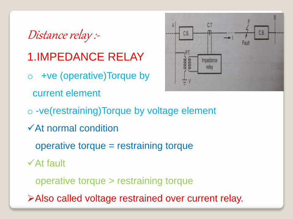
Distance relay :-
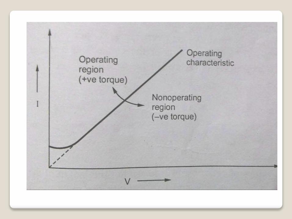
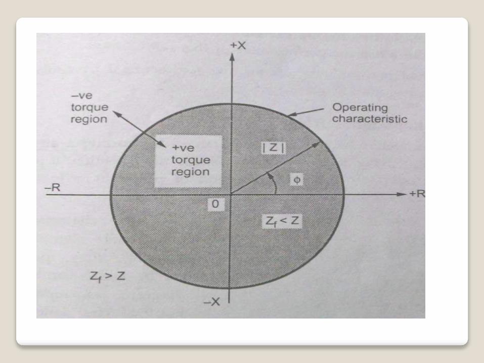
1.IMPEDANCE RELAY
o +ve (operative)Torque by
current element
o -ve(restraining)Torque by voltage element
At normal condition
operative torque = restraining torque
At fault
operative torque > restraining torque
Also called voltage restrained over current relay.
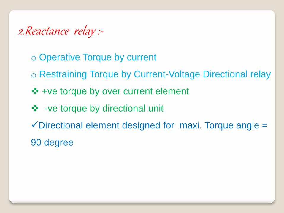
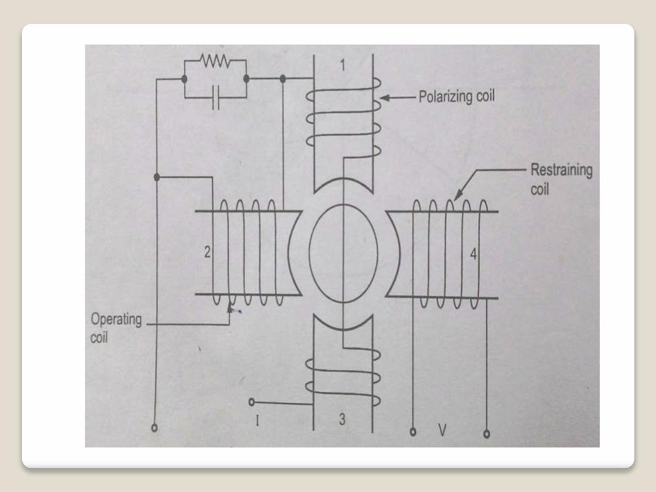
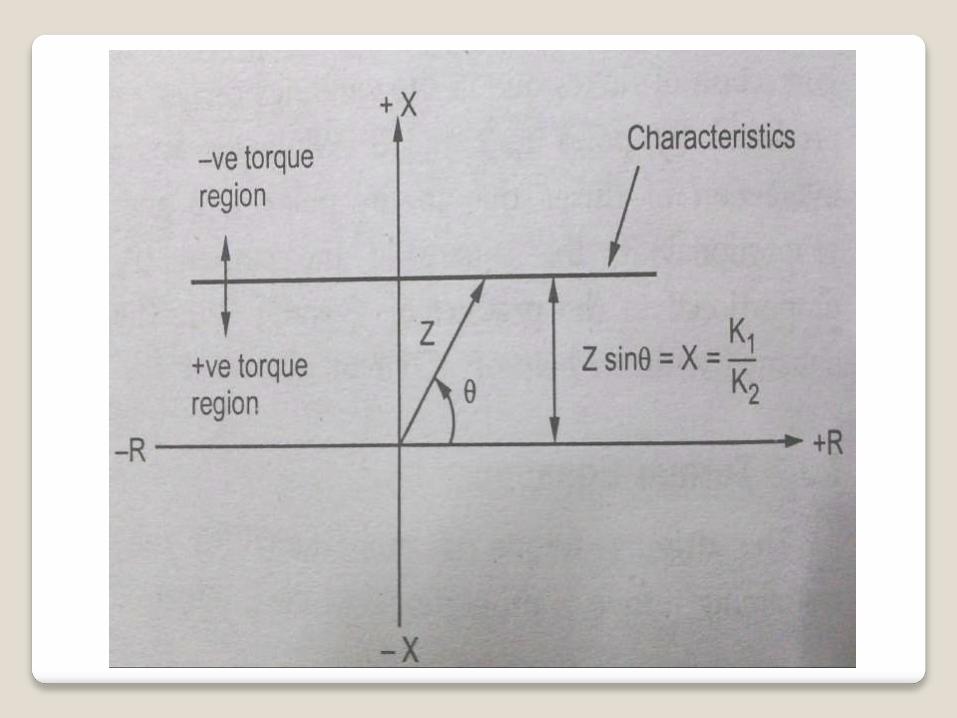
2.Reactance relay :-
o Operative Torque by current
o Restraining Torque by Current-Voltage Directional relay
+ve torque by over current element
-ve torque by directional unit
Directional element designed for maxi. Torque angle =
90 degree
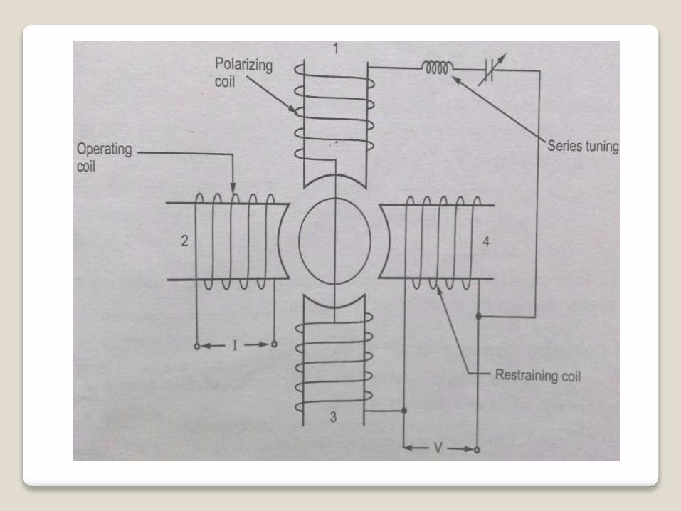
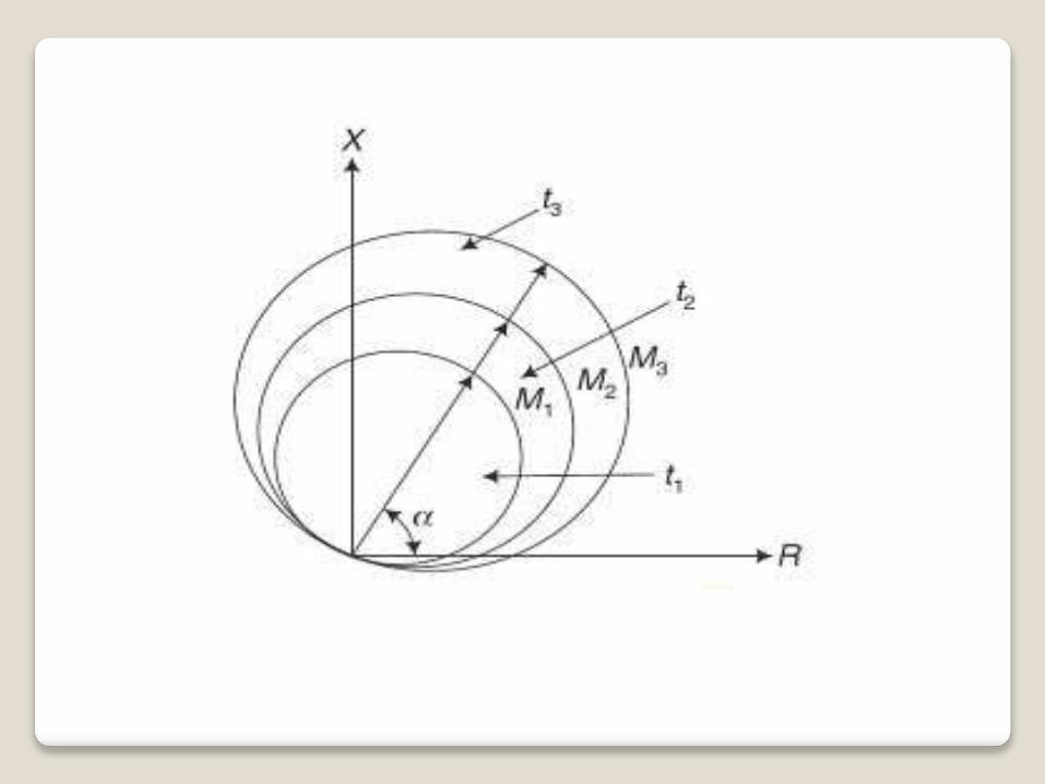
3.Mho relay :-
Induction cup type structure.
oOperative Torque produced by V & I element.
o Restraining Torque by Voltage element.
Also called Admittance relay.
Digital protective relay
Protective relay that uses a micro
processor to analyze power system
voltages, currents or other process
quantities for the purpose of detection
of faults in an industrial process
system.
Also called NEUMERIC RELAY.
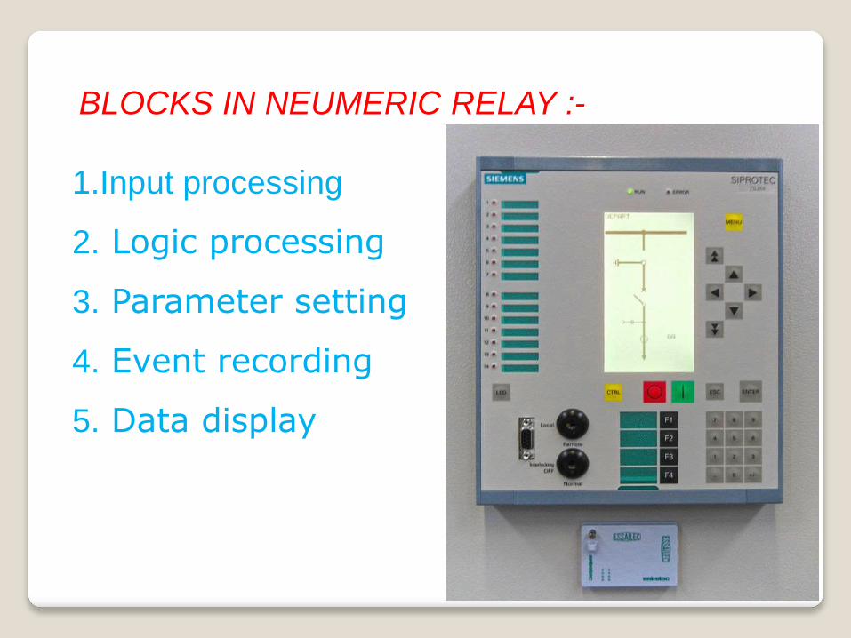
1.Input processing
2. Logic processing
3. Parameter setting
4. Event recording
5. Data display
BLOCKS IN NEUMERIC RELAY :-
REFERENCES :-
https://www.wikipedia.org/
https://books.google.co.in/books?isbn=8184316399
Induction Type Relays. CircuitManiac.com. Accessed
March 8th, 2012.
Fundamental Relay-Operating Principles and Characteristics.
G.E. Digital Energy. Accessed March 8th, 2012.
www.google.co.in