Embed Size (px)
Citation preview

PNOZ m1p (ETH)
Operating Manual20878EN13
Configurable Control System PNOZmulti

PrefaceThis document is the original document.
All rights to this documentation are reserved by Pilz GmbH & Co. KG. Copies may be madefor internal purposes. Suggestions and comments for improving this documentation will begratefully received.
Pilz®, PIT®, PMI®, PNOZ®, Primo®, PSEN®, PSS®, PVIS®, SafetyBUS p®,SafetyEYE®, SafetyNET p®, the spirit of safety® are registered and protected trademarksof Pilz GmbH & Co. KG in some countries.
SD means Secure Digital

Content
Operating Manual PNOZ m1p (ETH)20878EN13
3
Section 1 Introduction 51.1 Validity of documentation 51.2 Using the documentation 51.3 Definition of symbols 5
Section 2 Overview 72.1 Range 72.2 Unit features 72.3 Chip card 82.4 Front view 8
Section 3 Safety 113.1 Intended use 113.2 System requirements 113.3 Safety regulations 113.3.1 Safety assessment 113.3.2 Use of qualified personnel 113.3.3 Warranty and liability 123.3.4 Disposal 123.3.5 For your safety 12
Section 4 Function description 134.1 Integrated protection mechanisms 134.2 Functions 134.3 Block diagram 134.4 Diagnostics 144.5 Cascading 144.6 Safety mat, muting 144.7 Interfaces 14
Section 5 Installation 155.1 General installation guidelines 155.2 Dimensions 165.3 Install base unit without expansion module 165.4 Connecting the base unit and expansion modules 17
Section 6 Commissioning 186.1 Wiring 186.2 Ethernet interfaces (only PNOZ m1p ETH) 196.2.1 RJ45 interfaces ("Ethernet") 196.2.2 Requirements of the connection cable and connector 196.2.3 Interface configuration 196.2.4 RJ45 connection cable 206.2.5 Process data exchange 216.3 Preparing for operation 226.3.1 Function test during commissioning 226.3.2 Commissioning the PNOZmulti control system for the first time 22

Content
Operating Manual PNOZ m1p (ETH)20878EN13
4
6.3.2.1 Load project from chip card 226.3.2.2 Load project via integrated interface 236.3.3 Download modified project to the control system PNOZmulti 236.3.3.1 Load modified project from chip card 236.3.3.2 Load modified project via integrated interface 236.3.4 Connection 246.4 Connection example 26
Section 7 Operation 277.1 LEDs 277.1.1 Display elements for the Ethernet connection (only PNOZ m1p ETH) 297.2 Reset Ethernet connection settings 29
Section 8 Technical Details 308.1 Safety characteristic data 37
Section 9 Supplementary data 389.1 Maximum capacitive load C (μF) with load current I (mA) at the semicon
ductor outputs38
9.2 Service life graph of output relays 38
Section 10 Order reference 4010.1 Product 4010.2 Accessories 40

Introduction
Operating Manual PNOZ m1p (ETH)20878EN13
5
1 Introduction
1.1 Validity of documentationThis documentation is valid for the product PNOZ m1p. It is valid until new documentationis published.
This operating manual explains the function and operation, describes the installation andprovides guidelines on how to connect the product.
1.2 Using the documentationThis document is intended for instruction. Only install and commission the product if youhave read and understood this document. The document should be retained for future reference.
1.3 Definition of symbolsInformation that is particularly important is identified as follows:
DANGER!
This warning must be heeded! It warns of a hazardous situation that posesan immediate threat of serious injury and death and indicates preventivemeasures that can be taken.
WARNING!
This warning must be heeded! It warns of a hazardous situation that couldlead to serious injury and death and indicates preventive measures that canbe taken.
CAUTION!
This refers to a hazard that can lead to a less serious or minor injury plusmaterial damage, and also provides information on preventive measuresthat can be taken.
NOTICE
This describes a situation in which the product or devices could be damaged and also provides information on preventive measures that can betaken. It also highlights areas within the text that are of particular importance.

Introduction
Operating Manual PNOZ m1p (ETH)20878EN13
6
INFORMATION
This gives advice on applications and provides information on special features.

Overview
Operating Manual PNOZ m1p (ETH)20878EN13
7
2 Overview
2.1 Range Base unit PNOZ m1p
Terminator
Documentation on data medium
2.2 Unit featuresUsing the product PNOZ m1p:
Base unit from the configurable control system PNOZmulti
The product has the following features:
Can be configured in the PNOZmulti Configurator
Positiveguided relay outputs:– 2 safety outputs
Depending on the application, up to PL e of EN ISO 138491 and up to SIL CL 3 ofEN IEC 62061
Semiconductor outputs:– 4 safety outputs
Depending on the application, up to PL e of EN ISO 138491 and up to SIL CL 3 ofEN IEC 62061
– 1 output for standard applications
4 test pulse outputs
1 cascading input and output;can also be used as a standard output
20 inputs for connecting, for example:– ESTOP pushbuttons
– Twohand buttons
– Safety gate limit switches
– Start buttons
– Light beam devices
– Scanners
– Enabling switches
– PSEN
– Operating mode selector switches
– Pressure sensitive mats
Muting function
LED for:– Diagnostics
– Supply voltage
– Output circuits

Overview
Operating Manual PNOZ m1p (ETH)20878EN13
8
– Input circuits
Test pulse outputs used to monitor shorts across the inputs
Monitoring of shorts between the safety outputs
Expansion modules can be connected(please refer to the document "PNOZmulti System Expansion" for details of the typeand number that can be connected)
Integrated interfaces:– PNOZ m1p: Serial interface RS232
– PNOZ m1p ETH: 2 Ethernet interfaces Plugin connection terminals:
either springloaded terminal or screw terminal available as an accessory (see orderreference)
Coated version:Increased environmental requirements (see Technical details)
2.3 Chip cardTo be able to use the product you will need a chip card.
Chip cards are available with memories of 8 kByte and 32 kByte. For largescale projectswe recommend the 32 kByte chip card (see Technical Catalogue: Accessories chapter).
2.4 Front view
PNOZ m1p
CHIP-Card
Overview
Operating Manual PNOZ m1p (ETH)20878EN13
9
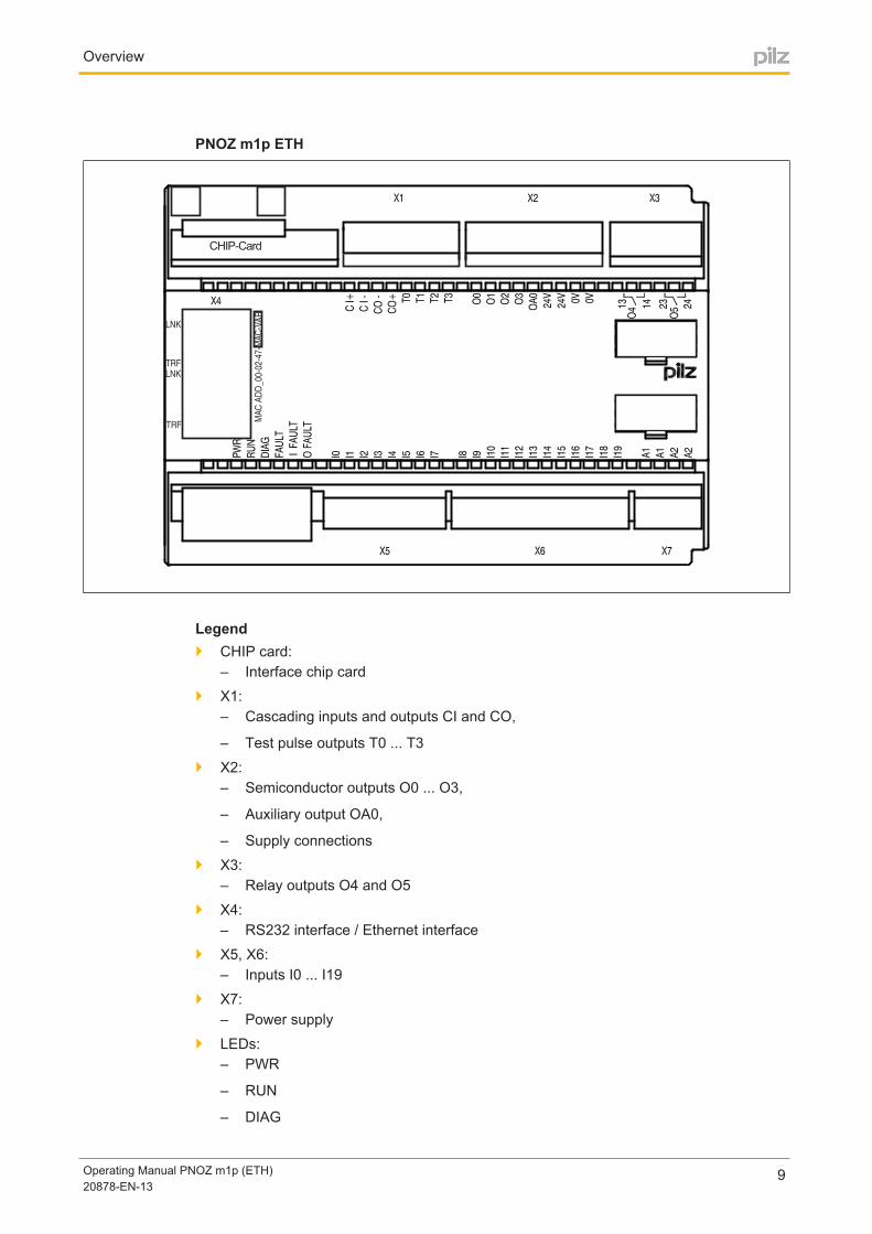
PNOZ m1p ETH
CHIP-Card
TRF
LNK
TRF
LNK
MA
C A
DD
_00-0
2-4
7-M
AC
-VA
R
Legend CHIP card:
– Interface chip card
X1:– Cascading inputs and outputs CI and CO,
– Test pulse outputs T0 ... T3
X2:– Semiconductor outputs O0 ... O3,
– Auxiliary output OA0,
– Supply connections
X3:– Relay outputs O4 and O5
X4:– RS232 interface / Ethernet interface
X5, X6:– Inputs I0 ... I19
X7:– Power supply
LEDs:– PWR
– RUN
– DIAG

Overview
Operating Manual PNOZ m1p (ETH)20878EN13
10
– FAULT
– I FAULT
– O FAULT

Safety
Operating Manual PNOZ m1p (ETH)20878EN13
11
3 Safety
3.1 Intended useThe configurable control system PNOZmulti is used for the safetyrelated interruption ofsafety circuits and is designed for use in:
ESTOP equipment
Safety circuits in accordance with VDE 0113 Part 1 and EN 602041
CAUTION!
Inputs and outputs for standard functions must not be used for safetyrelated applications.
The coated version of the product PNOZ m1p is suitable for use where there are increasedenvironmental requirements (see Technical Details).
Intended use includes making the electrical installation EMCcompliant. The product is designed for use in an industrial environment. It is not suitable for use in a domestic environment, as this can lead to interference.
The following is deemed improper use in particular:
Any component, technical or electrical modification to the product
Use of the product outside the areas described in this manual
Use of the product outside the technical details (see chapter entitled “Technical Details”)
3.2 System requirementsPlease refer to the "Product Modifications" document in the "Version overview" section fordetails of which versions of the PNOZmulti Configurator can be used for this product.
3.3 Safety regulations
3.3.1 Safety assessmentBefore using a unit it is necessary to perform a safety assessment in accordance with theMachinery Directive.
Functional safety is guaranteed for the product as a single component. However, this doesnot guarantee the functional safety of the overall plant/machine. In order to achieve the required safety level for the overall plant/machine, define the safety requirements for theplant/machine and then define how these must be implemented from a technical and organisational standpoint.
3.3.2 Use of qualified personnelThe products may only be assembled, installed, programmed, commissioned, operated,maintained and decommissioned by competent persons.
Safety
Operating Manual PNOZ m1p (ETH)20878EN13
12
A competent person is someone who, because of their training, experience and current professional activity, has the specialist knowledge required to test, assess and operate thework equipment, devices, systems, plant and machinery in accordance with the generalstandards and guidelines for safety technology.
It is the company’s responsibility only to employ personnel who:
Are familiar with the basic regulations concerning health and safety / accident prevention
Have read and understood the information provided in this description under "Safety"
And have a good knowledge of the generic and specialist standards applicable to thespecific application.
3.3.3 Warranty and liabilityAll claims to warranty and liability will be rendered invalid if
The product was used contrary to the purpose for which it is intended
Damage can be attributed to not having followed the guidelines in the manual
Operating personnel are not suitably qualified
Any type of modification has been made (e.g. exchanging components on the PCBboards, soldering work etc.).
3.3.4 Disposal In safetyrelated applications, please comply with the mission time TM in the safetyre
lated characteristic data.
When decommissioning, please comply with local regulations regarding the disposal ofelectronic devices (e.g. Electrical and Electronic Equipment Act).
3.3.5 For your safetyThe unit meets all the necessary conditions for safe operation. However, you should alwaysensure that the following safety requirements are met:
This operating manual only describes the basic functions of the unit. Advanced functions such as cascading are described in the online help for the PNOZmulti Configurator, in the document entitled "PNOZmulti Communication Interfaces" and in"PNOZmulti Special Applications". Only use these functions once you have read andunderstood the documentation.
Adequate protection must be provided for all inductive consumers.
Do not open the housing or make any unauthorised modifications.
Please make sure you shut down the supply voltage when performing maintenancework (e.g. exchanging contactors).

Function description
Operating Manual PNOZ m1p (ETH)20878EN13
13
4 Function description
4.1 Integrated protection mechanismsThe relay conforms to the following safety criteria:
The circuit is redundant with builtin selfmonitoring.
The safety function remains effective in the case of a component failure.
The relay contacts meet the requirements for protective separation through increasedinsulation compared with all other circuits in the safety system.
The safety outputs are tested periodically using a disconnection test.
4.2 FunctionsThe function of the inputs and outputs on the control system depends on the safety circuitcreated using the PNOZmulti Configurator. A chip card is used to download the safety circuit to the base unit. The base unit has 2 microcontrollers that monitor each other. Theyevaluate the input circuits on the base unit and expansion modules and switch the outputson the base unit and expansion modules accordingly.
The LEDs on the base unit and expansion modules indicate the status of the configurablecontrol system PNOZmulti.
The online help on the PNOZmulti Configurator contains descriptions of the operatingmodes and all the functions of the control system, plus connection examples.
4.3 Block diagram
Inte
rfa
ce
fi
eld
bu
s,
ex
pa
ns
ion
mo
du
le
Inte
rfa
ce
ch
ip c
ard
Eth
ern
et/
RS
23
2
Inte
rfa
ce
ex
pa
ns
ion
mo
du
leO4 O5
A1 A2 I0 I14I6 I11I9 I10 I13I8I7 I16I12 I18I15I2 I4 I5I1 I3 I17 I19
Input
Power
CascadingTest pulse
output24 V 0 V
24 V 0 V
1323
CI+ CI- CO+ CO- T0 T1 T2 T3 O0 O1 O2 O3 OA0 14 24

Function description
Operating Manual PNOZ m1p (ETH)20878EN13
14
4.4 DiagnosticsThe status and error messages displayed by the LEDs are saved in an error stack. This error stack can be read from the PNOZmulti Configurator via the interfaces (RS 232 or Ethernet). More comprehensive diagnostics are possible via the interfaces or one of the fieldbusmodules, e.g. the PROFIBUS module.
4.5 CascadingThe cascading inputs and outputs enable several PNOZmulti and PNOZelog units to beconnected in series or as a tree structure.
INFORMATION
Detailed information on these functions and connection examples can befound in the online help for the PNOZmulti Configurator and in thePNOZmulti Installation Manual.
4.6 Safety mat, muting
INFORMATION
Detailed information on these functions and connection examples can befound in the online help for the PNOZmulti Configurator and in the document entitled "PNOZmulti Special Applications".
4.7 InterfacesThe product PNOZ m1p ETH has two Ethernet interfaces, the product PNOZ m1p has oneserial interface to
Project download
Read the diagnostic data
Set virtual inputs for standard functions
Read virtual outputs for standard functions.
Information on diagnostics via the interfaces can be found in the document "PNOZmulticommunication interfaces".
The connection to Ethernet is made via the two 8pin RJ45 sockets.The Ethernet interface is configured in the PNOZmulti Configurator and is described in theonline help for the PNOZmulti Configurator.

Installation
Operating Manual PNOZ m1p (ETH)20878EN13
15
5 Installation
5.1 General installation guidelines The control system should be installed in a control cabinet with a protection type of at
least IP54. Fit the control system to a horizontal mounting rail. The venting slots mustface upward and downward. Other mounting positions could destroy the control system.
Use the notches on the rear of the unit to attach it to a mounting rail. Connect the control system to the mounting rail in an upright position, so that the earthing springs on thecontrol system are pressed on to the mounting rail.
The ambient temperature of the PNOZmulti units in the control cabinet must not exceedthe figure stated in the technical details, otherwise air conditioning will be required.
To comply with EMC requirements, the mounting rail must have a low impedance connection to the control cabinet housing.
CAUTION!
Damage due to electrostatic discharge!
Electrostatic discharge can damage components. Ensure against dischargebefore touching the product, e.g. by touching an earthed, conductive surface or by wearing an earthed armband.

Installation
Operating Manual PNOZ m1p (ETH)20878EN13
16
5.2 Dimensions
94 (3.70")
121 (4.7
6")
135 (5.31")
5.3 Install base unit without expansion module The terminator must be fitted to the side of the base unit marked “Termination/Link”.
Do not fit a terminator on the left hand side of the base unit.
Terminator Termination/Link
Installation
Operating Manual PNOZ m1p (ETH)20878EN13
17
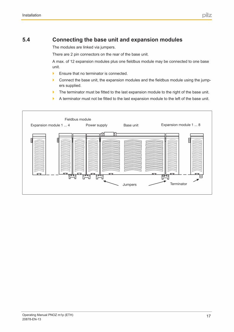
5.4 Connecting the base unit and expansion modulesThe modules are linked via jumpers.
There are 2 pin connectors on the rear of the base unit.
A max. of 12 expansion modules plus one fieldbus module may be connected to one baseunit.
Ensure that no terminator is connected.
Connect the base unit, the expansion modules and the fieldbus module using the jumpers supplied.
The terminator must be fitted to the last expansion module to the right of the base unit.
A terminator must not be fitted to the last expansion module to the left of the base unit.
Expansion module 1 ... 8
Jumpers Terminator
Fieldbus module
Base unitExpansion module 1 ... 4 Power supply

Commissioning
Operating Manual PNOZ m1p (ETH)20878EN13
18
6 Commissioning
6.1 WiringThe wiring is defined in the circuit diagram in the Configurator. There you can select the inputs that are to perform a safety function and the outputs that are to switch this safety function.
Note:
CAUTION!
The plugin connection terminals on the relay outputs that carry mainsvoltage should only be connected and disconnected when the voltage isswitched off.
Information given in the "Technical details" must be followed.
Outputs:– O0 to O5 are safety outputs.
– O4 and O5 are relay outputs
– O0 to O3 are semiconductor outputs
– OA0 is an output to delete a project from the base unit (see online help for thePNOZmutli Configurator).
To prevent contact welding, a fuse should be connected before the output contacts (seetechnical details).
Use copper wire that can withstand 75°C.
Sufficient fuse protection must be provided on all output contacts with inductive loads.
The control system and input circuits must always be supplied by a single power supply. The power supply must meet the regulations for extra low voltages with protectiveseparation.
Two connection terminals are available for each of the supply connections 24 V and 0 V(semiconductor outputs), plus A1 and A2 (power supply). This means that the supplyvoltage can be looped through several connections. The current at each terminal maynot exceed 3 A.
Test pulse outputs must exclusively be used to test the inputs. They must not be usedto drive loads. Do not route the test pulse lines together with actuator cables within an unprotectedmulticore cable.
Test pulse outputs are also used to supply safety mats that trigger a short circuit.Test pulses that are used for the safety mat may not be reused for other purposes.

Commissioning
Operating Manual PNOZ m1p (ETH)20878EN13
19
6.2 Ethernet interfaces (only PNOZ m1p ETH)
6.2.1 RJ45 interfaces ("Ethernet")Two free switch ports are provided as Ethernet interfaces via an internal autosensingswitch. The autosensing switch automatically detects whether data transfer is occurring at10 Mbit/s or 100 Mbit/s.
INFORMATION
The connected subscribers must support the autosensing/autonegotiationfunction. If not, the communication partner must be set permanently to "10Mbit/s, half duplex".
The switch's automatic crossover function means there is no need to distinguish on theconnection cable between patch cable (uncrossed data line connection) and crossovercable (crossover data line connection). The switch automatically creates the correct dataline connection internally. Patch cable can therefore be used as the connection cable forend devices as well as cascading.
Both Ethernet interfaces use RJ45 technology.
6.2.2 Requirements of the connection cable and connectorThe following minimum requirements must be met:
Ethernet standards (min. Category 5) 10BaseT or 100BaseTX
Doubleshielded twisted pair cable for industrial Ethernet use
Shielded RJ45 connectors (industrial connectors)
6.2.3 Interface configurationRJ45 socket8pin PIN Standard Crossover
8 1
1 TD+ (Transmit+) RD+ (Receive+)
2 TD (Transmit) RD (Receive)
3 RD+ (Receive+) TD+ (Transmit+)
4 n.c. n.c.
5 n.c. n.c.
6 RD (Receive) TD (Transmit)
7 n.c. n.c.
8 n.c. n.c.

Commissioning
Operating Manual PNOZ m1p (ETH)20878EN13
20
6.2.4 RJ45 connection cableRJ45 connector8pin
8
1
10BaseT cable or 100BaseTX cable
max. 100 m
NOTICE
With the plugin connection please note that the data cable and connectorhave a limited mechanical load capacity. Appropriate design measuresshould be used to ensure that the plugin connection is insensitive to increased mechanical stress (e.g. through shock, vibration). Such measuresinclude fixed routing with strain relief, for example.

Commissioning
Operating Manual PNOZ m1p (ETH)20878EN13
21
6.2.5 Process data exchangeThe RJ45 interfaces on the internal autosensing switch enable process data to be exchanged with other Ethernet subscribers within a network.
The product PNOZ m1p ETH can also be connected to Ethernet via a hub (hub or switch).
Ethernet
Hub/Switch Hub/Switch
Ethernet subscriber Ethernet subscriber
PNOZmulti base unitwith Ethernet interface
PNOZmulti base unitwith Ethernet interface
PC with PNOZmultiConfigurator
Fig.: PNOZmulti as Ethernet subscriber possible topologies

Commissioning
Operating Manual PNOZ m1p (ETH)20878EN13
22
6.3 Preparing for operation
6.3.1 Function test during commissioning
CAUTION!
It is essential to check that the safety devices operate correctly
– after the chip card has been exchanged
– after a project has been downloaded
– when the project has been deleted from the base unit's memory ("Reset Project" menu)
6.3.2 Commissioning the PNOZmulti control system for the first timeProcedure:
Wire the inputs and outputs on the base unit and expansion modules in accordancewith the circuit diagram.
Cascading output as auxiliary output: Connect the load to CO+ and A2, see connectionexample.
Connect the supply voltage:– Supply voltage for the units (connector X7):
– Terminal A1: + 24 VDC
– Terminal A2: 0 V
– Supply voltage for the semiconductor outputs (connector X2):
– 24 V terminal: + 24 VDC
– 0V terminal: 0 V
Please note: Supply voltage must always be applied to X2 and X7, even if you are not using the semiconductor outputs.
6.3.2.1 Load project from chip card
NOTICE
Chip contacting is only guaranteed if the contact surface is clean and undamaged. The chip's contact surface should therefore be protected fromcontamination, contact and mechanical impact such as scratches.
Procedure:
Insert the chip card containing the current project into the card slot on the base unit.
Switch on the supply voltage.

Commissioning
Operating Manual PNOZ m1p (ETH)20878EN13
23
6.3.2.2 Load project via integrated interfaceProcedure:
Insert a chip card into the chip card slot on the base unit.
Connect the computer containing the PNOZmulti Configurator to the base unit via theinterface.
Switch on the supply voltage.
Download the project (see PNOZmulti Configurator's online help).
INFORMATION
You will need a PC with an Ethernet card in order to establish an Ethernetconnection.
6.3.3 Download modified project to the control system PNOZmulti
6.3.3.1 Load modified project from chip cardTo download data via chip card, the existing configuration data must first be deleted (general reset of device).
Procedure:
Switch off the supply voltage.
Disconnect all the output terminals.
Jumper OA0I19 on the base unit.
Switch on the supply voltage.
When the "DIAG" LED on the base unit flashes, the memory has been cleared. The projectdata can now be downloaded:
Switch off the supply voltage.
Remove the old chip card from the chip card slot on the base unit.
Remove the jumper from OA0I19 on the base unit.
Insert the chip card containing the current project into the card slot.
Switch on the supply voltage.
6.3.3.2 Load modified project via integrated interfaceProceed as described for the initial commissioning

Commissioning
Operating Manual PNOZ m1p (ETH)20878EN13
24
6.3.4 Connection
Supply voltage AC DC
For the safety system(connector X7)
A1 + 24 V DC
A2 0 V
For the semiconductor outputs(connector X2)Must always be present, even ifthe semiconductor outputs are notused
24 V + 24 V DC
0 V 0 V
Supply voltage
Input circuit Singlechannel Dualchannel
ESTOPwithout detection of shorts acrosscontacts
S1
I0 L+S1
I1
I0 L+
L+
ESTOPwith detection of shorts acrosscontacts
I0
T0
S1
S1
T1
I1
T0
I0
Connection examples for the input circuit
Start circuit Input circuit without detection ofshorts across contacts
Input circuit with detection ofshorts across contacts
I5
S3
L+
I5
T0
S3
Connection examples for start circuit

Commissioning
Operating Manual PNOZ m1p (ETH)20878EN13
25
Redundant output
K2L-
O0 (O2)
O1 (O3)
K1L-
Single output
K3L-
K4
O0 (O2)
O1 ( O3)
K1L-
K2
Connection examples for semiconductor outputs
Redundant output
O5 K1
L1
N
K2
14
13
23
24
O4
Single output
O5 K1
L1
N
K214
13
23
24
O4
Connection examples for relay outputs

Commissioning
Operating Manual PNOZ m1p (ETH)20878EN13
26
Feedback loop Redundant output
Contacts from external contactors K1
L+
L-
K2
O0 (O2, O4)
O1 (O3, O5)
I0
L-
Connection examples for feedback loop
6.4 Connection exampleDualchannel ESTOP and safety gate wiring, monitored start (I17), feedback loop (I14),cascading output as auxiliary output (CO+/A2)
I0 I1 I2 I3 I4 I5 I6 I7 I8 I9 I10
I11
I12
I13
I14
I15
I16
I17
I18
I19
A1
A1
A2
A2
CI+
CI-
CO-
CO+
T0
T1
T2
T3
O0
O1
O2
O3
OA0
24V
24V
0V
0V
13
14
23
24
K1
K2S1
K2
K1
S2
S3
L+
L-

Operation
Operating Manual PNOZ m1p (ETH)20878EN13
27
7 OperationWhen the supply voltage is switched on, the PNOZmulti safety system copies the configuration from the chip card.
The LEDs "POWER","DIAG", "FAULT", "IFAULT" and "OFAULT" light up on the base unit.
The PNOZmulti control system is ready for operation when the "POWER" and "RUN" LEDson the base unit are lit continuously.
7.1 LEDsLegend:
LED on
LED flashes
LED off
Base Exp. Error
InputIx
RUN DIAG FAULT IFAULT OFAULT CI CO FAULT IN/OUT
The existing userprogram has beendeleted.
External error on thebase unit, leading toa safe condition,e.g. terminator notconnected
External error leading to a safe condition, e.g. shortacross the contactsor error at safetymat input
External error on thebase unit outputs,e.g. short across thecontacts, leading toa safe condition.
External error, leading to a safe condition, e.g. shortacross the contacts
External error on theoutput
Internal error on thebase unit
Operation
Operating Manual PNOZ m1p (ETH)20878EN13
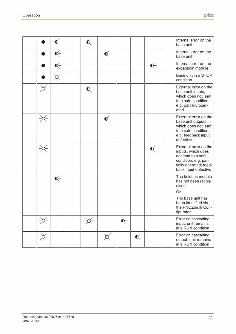
28
Internal error on thebase unit
Internal error on thebase unit
Internal error on theexpansion module
Base unit in a STOPcondition
External error on thebase unit inputs,which does not leadto a safe condition,e.g. partially operated
External error on thebase unit outputs,which does not leadto a safe condition,e.g. feedback inputdefective
External error on theinputs, which doesnot lead to a safecondition, e.g. partially operated; feedback input defective
The fieldbus modulehas not been recognised.OrThe base unit hasbeen identified viathe PNOZmulti Configurator.
Error on cascadinginput; unit remainsin a RUN condition
Error on cascadingoutput; unit remainsin a RUN condition

Operation
Operating Manual PNOZ m1p (ETH)20878EN13
29
7.1.1 Display elements for the Ethernet connection (only PNOZ m1p ETH)The operating and fault states of the Ethernet connection are displayed via the LNK (Link)and TRF (Traffic) LEDs on the Ethernet interfaces.
LED Signal Meaning
LNK(green)
No network connection
Network connection present
TRF (yellow)
No data traffic
Data traffic present
7.2 Reset Ethernet connection settingsThe Ethernet connection settings of the base unit can be configured in the PNOZmulti Configurator.
You can reset the base unit's Ethernet connection settings to the default settings.
Proceed as follows:
Switch off the supply voltage
Remove the chip card
Restart the base unit without the chip card inserted.
The Ethernet connection settings are now reset to the default settings.

Technical Details
Operating Manual PNOZ m1p (ETH)20878EN13
30
8 Technical Details
General 773100 773103 773104 773105
Approvals
BG, CCC, CE, EAC(Eurasian), KCC,KOSHA, TÜV,cULus Listed
BG, CCC, CE, EAC(Eurasian), KCC,TÜV, cULus Listed
BG, CCC, CE, EAC(Eurasian), TÜV,cULus Listed
BG, CCC, CE, EAC(Eurasian), KCC,KOSHA, TÜV,cULus Listed
Electrical data 773100 773103 773104 773105Supply voltage
for Supply to the system
Supply to the system
Supply to the system
Supply to the system
Voltage 24,0 V 24,0 V 24,0 V 24,0 VKind DC DC DC DCVoltage tolerance 15 %/+20 % 15 %/+20 % 15 %/+20 % 15 %/+20 %Output of externalpower supply(DC) 8,0 W 9,0 W 9,0 W 8,0 WResidual rippleDC 5 % 5 % 5 % 5 %
Supply voltagefor Supply to the SC
outputsSupply to the SCoutputs
Supply to the SCoutputs
Supply to the SCoutputs
Voltage 24 V 24 V 24 V 24 VKind DC DC DC DCVoltage tolerance 15 %/+20 % 15 %/+20 % 15 %/+20 % 15 %/+20 %Residual rippleDC 5 % 5 % 5 % 5 %Potential isolation Yes Yes Yes Yes
Supply voltagePower consumption per expansion module 2,50 W 2,50 W 2,50 W 2,50 W
Status indicator LED LED LED LEDInputs 773100 773103 773104 773105Number 20 20 20 20Max. number of liveinputs in the area ofmax. permitted ambient temperature(see "Environmentaldata")
U_B <= 26,4 V : 20,U_B > 26,4 V : 15
U_B <= 26,4 V : 20,U_B > 26,4 V : 15
U_B <= 26,4 V : 20,U_B > 26,4 V : 15
U_B <= 26,4 V : 20,U_B > 26,4 V : 15
Signal level at "0" 3 +5 V DC 3 +5 V DC 3 +5 V DC 3 +5 V DCSignal level at "1" 15 30 V DC 15 30 V DC 15 30 V DC 15 30 V DCInput voltage in accordance with EN611312 Type 1 24 V DC 24 V DC 24 V DC 24 V DCInput current at ratedvoltage 8 mA 8 mA 8 mA 8 mAMin. pulse duration 18 ms 18 ms 18 ms 18 msPulse suppression 0,6 ms 0,6 ms 0,6 ms 0,6 ms

Technical Details
Operating Manual PNOZ m1p (ETH)20878EN13
31
Inputs 773100 773103 773104 773105Maximum inputdelay 4 ms 4 ms 4 ms 4 msPotential isolation No No No NoSemiconductoroutputs
773100 773103 773104 773105
Number 4 4 4 4Switching capability
Voltage 24 V 24 V 24 V 24 VCurrent 2,0 A 2,0 A 2,0 A 2,0 APower 48 W 48 W 48 W 48 W
Voltage – – 24 V 24 VCurrent – – 1 A 1 APower – – 24 W 24 W
Signal level at "1" UB 0.5 VDC at 2 A UB 0.5 VDC at 2 A UB 0.5 VDC at 2 A UB 0.5 VDC at 2 AResidual current at"0" 0,5 mA 0,5 mA 0,5 mA 0,5 mAMax. capacitive load 1 µF 1 µF 1 µF 1 µFMax. duration of offtime during self test 300 µs 300 µs 300 µs 300 µsSwitchoff delay 30 ms 30 ms 30 ms 30 msPotential isolation Yes Yes Yes YesShort circuitproof Yes Yes Yes YesSemiconductoroutputs (standard)
773100 773103 773104 773105
Number 1 1 1 1Switching capability
Voltage 24 V 24 V 24 V 24 VCurrent 0,50 A 0,50 A 0,50 A 0,50 APower 12,0 W 12,0 W 12,0 W 12,0 W
Galvanic isolation Yes Yes Yes YesShort circuitproof Yes Yes Yes YesResidual current at"0" 0,5 mA 0,5 mA 0,5 mA 0,5 mA
Signal level at "1"UB 0.5 VDC at 0.5A
UB 0.5 VDC at 0.5A
UB 0.5 VDC at 0.5A
UB 0.5 VDC at 0.5A
Test pulse outputs 773100 773103 773104 773105Number of test pulseoutputs 4 4 4 4Voltage 24 V 24 V 24 V 24 VCurrent 0,5 A 0,5 A 0,5 A 0,5 AMax. duration of offtime during self test 5 ms 5 ms 5 ms 5 msShort circuitproof Yes Yes Yes YesPotential isolation No No No No

Technical Details
Operating Manual PNOZ m1p (ETH)20878EN13
32
Relay outputs 773100 773103 773104 773105Utilisation category
In accordancewith the standard EN 6094741 EN 6094741 EN 6094741 EN 6094741
Utilisation categoryof safety contacts
AC1 at 240 V 240 V 240 V 240 VMax. current 6,0 A 6,0 A 6,0 A 6,0 AMax. power 1440 VA 1440 VA 1440 VA 1440 VADC 1 at 24 V 24 V 24 V 24 VMax. current 6,0 A 6,0 A 6,0 A 6,0 AMax. power 144 W 144 W 144 W 144 W
Safety contacts,AC1 at – – 240 V 240 VMax. current – – 4 A 4 AMax. power – – 960 W 960 WSafety contacts,DC 1 at – – 24 V 24 VMax. current – – 4 A 4 AMax. power – – 96 W 96 W
Utilisation categoryIn accordancewith the standard EN 6094751 EN 6094751 EN 6094751 EN 6094751
Utilisation categoryof safety contacts
AC15 at 230 V 230 V 230 V 230 VMax. current 3,0 A 3,0 A 3,0 A 3,0 AMax. power 690 W 690 W 690 W 690 WDC13 (6 cycles/min) at 24 V 24 V 24 V 24 VMax. current 3,0 A 3,0 A 3,0 A 3,0 AMax. power 72 W 72 W 72 W 72 W
Airgap creepagebetween
Relay contacts 3 mm 3 mm 3 mm 3 mmRelay contactsand other circuits 5,5 mm 5,5 mm 5,5 mm 5,5 mm
Contact fuse protection external, safetycontacts
In accordancewith the standard EN 6094751 EN 6094751 EN 6094751 EN 6094751Blowout fuse,quick 6 A 6 A 6 A 6 ABlowout fuse,slow 6,00 A 6,00 A 6,00 A 6,00 ACircuit breaker,24V AC/DC, characteristic B/C 6 A 6 A 6 A 6 A

Technical Details
Operating Manual PNOZ m1p (ETH)20878EN13
33
Relay outputs 773100 773103 773104 773105Switchoff delay 50 ms 50 ms 50 ms 50 msPotential isolation Yes Yes Yes YesCascading outputas standard output
773100 773103 773104 773105
Number 1 1 1 1Switching capability
Voltage 24 V 24 V 24 V 24 VCurrent 0,2 A 0,2 A 0,2 A 0,2 APower 4,8 W 4,8 W 4,8 W 4,8 W
Galvanic isolation No No No NoShort circuitproof Yes Yes Yes YesResidual current at"0" 0,5 mA 0,5 mA 0,5 mA 0,5 mAEthernet interface 773100 773103 773104 773105Number – 2 2 –Serial interface 773100 773103 773104 773105Number of RS232interfaces 1 – – 1Times 773100 773103 773104 773105Switchon delay 5,00 s 5,00 s 5,00 s 5,00 sSupply interruptionbefore deenergisation 20 ms 20 ms 20 ms 20 msSimultaneity, channel 1 and 2 3 s 3 s 3 s 3 sSimultaneity in thetwohand circuit 0,5 s 0,5 s 0,5 s 0,5 sMax. cycle time ofthe device 15 ms 15 ms 15 ms 15 msMax. processingtime for data communication – 50 ms 50 ms –Environmental data 773100 773103 773104 773105Ambient temperature
In accordancewith the standard EN 60068214 EN 60068214 EN 60068214 EN 60068214Temperaturerange 0 60 °C 0 60 °C 25 60 °C 25 60 °CForced convection in controlcabinet off 55 °C 55 °C – –
Storage temperatureIn accordancewith the standard EN 6006821/2 EN 6006821/2 EN 6006821/2 EN 6006821/2Temperaturerange 25 70 °C 25 70 °C 25 70 °C 25 70 °C

Technical Details
Operating Manual PNOZ m1p (ETH)20878EN13
34
Environmental data 773100 773103 773104 773105Climatic suitability
In accordancewith the standard
EN 60068230, EN60068278
EN 60068230, EN60068278
EN 60068230, EN60068278
EN 60068230, EN60068278
Humidity 93 % r. h. at 40 °C 93 % r. h. at 40 °C 93 % r. h. at 40 °C 93 % r. h. at 40 °CCondensation duringoperation
Not permitted Not permitted
Shortterm (onlywith separated extra low voltage)
Shortterm (onlywith separated extra low voltage)
EMC EN 611312 EN 611312 EN 611312 EN 611312Vibration
In accordancewith the standard EN 6006826 EN 6006826 EN 6006826 EN 6006826Frequency 10,0 150,0 Hz 10,0 150,0 Hz 5,0 500,0 Hz 5,0 500,0 HzAcceleration 1g 1g 1g 1g
Broadband noiseIn accordancewith the standard – – EN 60068264 EN 60068264Frequency – – 5 500 Hz 5 500 HzAcceleration – – 19 m/s² rms 19 m/s² rms
Corrosive gas checkSO2: Concentration 10 ppm, duration 10 days,passive – – DIN V 4004636 DIN V 4004636H2S: Concentration 1 ppm, duration 10 days,passive – – DIN V 4004637 DIN V 4004637
Shock stressIn accordancewith the standard EN 60068227 EN 60068227 EN 60068227 EN 60068227Acceleration 15g 15g 15g 15gDuration 11 ms 11 ms 11 ms 11 ms
Max. operatingheight above sealevel 2000 m 2000 m 2000 m 2000 mAirgap creepage
In accordancewith the standard EN 611312 EN 611312 EN 611312 EN 611312Overvoltage category III III III IIIPollution degree 2 2 2 2
Rated insulationvoltage 250 V 250 V 250 V 250 VRated impulse withstand voltage 6,00 kV 6,00 kV 6,00 kV 6,00 kV

Technical Details
Operating Manual PNOZ m1p (ETH)20878EN13
35
Environmental data 773100 773103 773104 773105Protection type
In accordancewith the standard EN 60529 EN 60529 EN 60529 EN 60529Mounting area(e.g. control cabinet) IP54 IP54 IP54 IP54Housing IP20 IP20 IP20 IP20Terminals IP20 IP20 IP20 IP20
Potential isolation 773100 773103 773104 773105Potential isolationbetween
SC output and system voltage
SC output and system voltage
SC output and system voltage
SC output and system voltage
Type of potentialisolation
Protective separation
Protective separation
Protective separation
Protective separation
Rated surge voltage 2500 V 2500 V 2500 V 2500 VPotential isolationbetween
RL output and system voltage
RL output and system voltage
RL output and system voltage
RL output and system voltage
Type of potentialisolation
Protective separation
Protective separation
Protective separation
Protective separation
Rated surge voltage 6000 V 6000 V 6000 V 6000 VMechanical data 773100 773103 773104 773105Mounting position Horizontal on top
hat railHorizontal on tophat rail
Horizontal on tophat rail
Horizontal on tophat rail
DIN railTop hat rail 35 x 7,5 EN 50022 35 x 7,5 EN 50022 35 x 7,5 EN 50022 35 x 7,5 EN 50022Recess width 27 mm 27 mm 27 mm 27 mm
Max. cable lengthMax. cable lengthper input 1,0 km 1,0 km 1,0 km 1,0 kmSum of individualcable lengths atthe test pulse output 40 km 40 km 40 km 40 km
MaterialBottom PPO UL 94 V0 PPO UL 94 V0 PPO UL 94 V0 PPO UL 94 V0Front ABS UL 94 V0 ABS UL 94 V0 ABS UL 94 V0 ABS UL 94 V0
Conductor crosssection with screwterminals (relay outputs)
1 core flexible 0,5 2,5 mm², 22 12 AWG
0,5 2,5 mm², 22 12 AWG
0,5 2,5 mm², 22 12 AWG
0,5 2,5 mm², 22 12 AWG
2 core with thesame cross section, flexiblewithout crimpconnectors orwith TWIN crimpconnectors
0,50 1,25 mm², 22 16 AWG
0,50 1,25 mm², 22 16 AWG
0,50 1,25 mm², 22 16 AWG
0,50 1,25 mm², 22 16 AWG

Technical Details
Operating Manual PNOZ m1p (ETH)20878EN13
36
Mechanical data 773100 773103 773104 773105Conductor crosssection with screwterminals
1 core flexible 0,50 1,50 mm², 22 14 AWG
0,50 1,50 mm², 22 14 AWG
0,50 1,50 mm², 22 14 AWG
0,50 1,50 mm², 22 14 AWG
2 core with thesame cross section, flexible withcrimp connectors,no plastic sleeve
0,50 0,75 mm², 22 20 AWG
0,50 0,75 mm², 22 20 AWG
0,50 0,75 mm², 22 20 AWG
0,50 0,75 mm², 22 20 AWG
2 core with thesame cross section, flexiblewithout crimpconnectors orwith TWIN crimpconnectors
0,50 0,75 mm², 22 20 AWG
0,50 0,75 mm², 22 20 AWG
0,50 0,75 mm², 22 20 AWG
0,50 0,75 mm², 22 20 AWG
Rigid singlecore,flexible multicoreor multicore withcrimp connector 0,5 1,5 mm² 0,5 1,5 mm² 0,5 1,5 mm² 0,5 1,5 mm²
Torque setting withscrew terminals 0,25 Nm 0,25 Nm 0,25 Nm 0,25 NmConnection type Cage clamp ter
minal, screw terminal
Cage clamp terminal, screw terminal
Cage clamp terminal, screw terminal
Cage clamp terminal, screw terminal
Conductor crosssection with springloaded terminals:Flexible with/withoutcrimp connector
0,50 1,50 mm², 26 14 AWG
0,50 1,50 mm², 26 14 AWG
0,50 1,50 mm², 26 14 AWG
0,50 1,50 mm², 26 14 AWG
Springloaded terminals: Terminalpoints per connection 1 1 1 1Stripping length 9,0 mm 9,0 mm 9,0 mm 9,0 mmDimensions
Height 94,0 mm 94,0 mm 94,0 mm 94,0 mmWidth 135,0 mm 135,0 mm 135,0 mm 135,0 mmDepth 121,0 mm 121,0 mm 121,0 mm 121,0 mm
Weight 499 g 518 g 538 g 519 g
Where standards are undated, the 201010 latest editions shall apply.

Technical Details
Operating Manual PNOZ m1p (ETH)20878EN13
37
8.1 Safety characteristic data
Unit Operatingmode
EN ISO138491: 2008PL
EN ISO138491: 2008Category
EN 62061SIL CL
EN 62061PFHD [1/h]
EN ISO138491: 2008TM [year]
LogicCPU 2channel PL e Cat. 4 SIL CL 3 4,90E09 20Expansion – PL e Cat. 4 SIL CL 3 9,20E09 20InputSC inputs 1channel PL d Cat. 2 SIL CL 2 2,50E09 20SC inputs 2channel PL e Cat. 4 SIL CL 3 2,90E10 20SC inputs Short circuit
formingsafety mats PL d Cat. 3 SIL CL 2 1,81E09 20
SC inputs 1ch., pulsedlight barrier PL e Cat. 4 SIL CL 3 2,50E10 20
Cascad. inputs – PL e Cat. 4 SIL CL 3 3,10E10 20OutputSC outputs 1channel PL d Cat. 2 SIL CL 2 7,00E09 20SC outputs 2channel PL e Cat. 4 SIL CL 3 8,60E10 20Cascad. outputs – PL e Cat. 4 SIL CL 3 4,91E10 20Relay outputs 1channel PL c Cat. 1 2,90E08 20Relay outputs 2channel PL e Cat. 4 SIL CL 3 3,00E10 20
All the units used within a safety function must be considered when calculating the safetycharacteristic data.
INFORMATION
A safety function's SIL/PL values are not identical to the SIL/PL values ofthe units that are used and may be different. We recommend that you usethe PAScal software tool to calculate the safety function's SIL/PL values.
CAUTION!
It is essential to consider the relay's service life graphs. The relay outputs'safetyrelated characteristic data is only valid if the values in the service lifegraphs are met.
The PFH value depends on the switching frequency and the load on the relay output.If the service life graphs are not accessible, the stated PFH value can be used irrespectiveof the switching frequency and the load, as the PFH value already considers the relay'sB10d value as well as the failure rates of the other components.

Supplementary data
Operating Manual PNOZ m1p (ETH)20878EN13
38
9 Supplementary data
9.1 Maximum capacitive load C (μF) with load current I (mA) atthe semiconductor outputs
2
4
0
0 10 50 100 200 400 600 800 1000 1200 I (mA)
6
1400 1600 1800 2000
C (µF)
9.2 Service life graph of output relaysThe service life graphs indicate the number of cycles from which failures due to wear mustbe expected. The wear is mainly caused by the electrical load; the mechanical load is negligible.

Supplementary data
Operating Manual PNOZ m1p (ETH)20878EN13
39
Example Inductive load: 0,2 A
Utilisation category: AC15
Contact service life: 1,000,000 cycles
Provided the application requires fewer than 1,000,000 cycles, the PFH value (see technical details) can be used in the calculation.
To increase the service life, sufficient spark suppression must be provided on all outputcontacts. With capacitive loads, any power surges that occur must be noted. With contactors, use freewheel diodes for spark suppression.
We recommend you use semiconductor outputs to switch 24 VDC loads.

Order reference
Operating Manual PNOZ m1p (ETH)20878EN13
40
10 Order reference
10.1 ProductProduct type Features Order no.
PNOZ m1p Base unit 773 100
PNOZ m1p coated version
Base unit, coated version 773 105
PNOZ m1p ETH Base unit, Ethernet interface 773 103
PNOZ m1p ETH coatedversion
Base unit, Ethernet interface, coated version 773 104
10.2 AccessoriesProduct type Features Order no.
Set spring terminals 1 set of springloaded terminals 783 100
Set screw terminals 1 set of screw terminals 793 100
Product type Features Order no.
PNOZmulti bus terminator Terminator 779 110
PNOZmulti bus terminatorcoated
Terminator, coated version 779 112
KOPXE Jumper 774 639
KOPXE coated Jumper, coated version 774 640

The Best of German En gineering
Partner of:
SupportTechnical support is available from Pilz round the clock.
Americas
Brazil
+55 11 97569-2804
Canada
+1 888-315-PILZ (315-7459)
Mexico
+52 55 5572 1300
USA (toll-free)
+1 877-PILZUSA (745-9872)
Asia
China
+86 21 60880878-216
Japan
+81 45 471-2281
South Korea
+82 31 450 0680
Australia
+61 3 95446300
Europe
Austria
+43 1 7986263-0
Belgium, Luxembourg
+32 9 3217575
France
+33 3 88104000
Germany
+49 711 3409-444
Ireland
+353 21 4804983
Italy
+39 0362 1826711
Scandinavia
+45 74436332
Spain
+34 938497433
Switzerland
+41 62 88979-30
The Netherlands
+31 347 320477
Turkey
+90 216 5775552
United Kingdom
+44 1536 462203
You can reach our
international hotline on:
+49 711 3409-444
CM
SE
®, I
nd
ura
NE
T p
®, P
AS
40
00
®, P
AS
cal
®, P
AS
con
fig
®, P
ilz
®, P
IT®
, PL
ID®
, PM
Cp
rim
o®
, PM
Cp
rote
go
®, P
MC
ten
do
®, P
MD
®, P
MI
®, P
NO
Z®
, Pri
mo
®, P
SE
N®
, PS
S®
, PV
IS®
, Sa
fety
BU
S p
®,
Sa
fety
EY
E®
, Sa
fety
NE
T p
®, t
he
sp
irit
of
safe
ty®
are
re
gis
tere
d a
nd
pro
tect
ed
tra
de
ma
rks
of
Pil
z G
mb
H &
Co
. KG
in s
om
e c
ou
ntr
ies.
We
wo
uld
po
int
ou
t th
at
pro
du
ct f
ea
ture
s m
ay
va
ry
fro
m t
he
de
tail
s st
ate
d in
th
is d
ocu
me
nt,
de
pe
nd
ing
on
th
e s
tatu
s a
t th
e t
ime
of
pu
bli
cati
on
an
d t
he
sco
pe
of
the
eq
uip
me
nt.
We
acc
ep
t n
o r
esp
on
sib
ilit
y f
or
the
va
lid
ity
, acc
ura
cy
an
d e
nti
rety
of
the
te
xt
an
d g
rap
hic
s p
rese
nte
d in
th
is in
form
ati
on
. Ple
ase
co
nta
ct o
ur
Tech
nic
al S
up
po
rt if
yo
u h
av
e a
ny
qu
est
ion
s.
Pilz develops environmentally-friendly products using
ecological materials and energy-saving technologies.
products and environmentally-friendly solutions.
Pilz GmbH & Co. KG
Felix-Wankel-Straße 2
73760 Ostfildern, Germany
Tel.: +49 711 3409-0
Fax: +49 711 3409-133
www.pilz.com
10
0X
XX
X-D
E-0
X
0-0
-2-3
-00
0, 2
01
4-0
0 P
rin
ted
in G
erm
an
y
© P
ilz G
mb
H &
Co
. KG
, 20
14
20878EN13, 201411 Printed in Germany
© Pilz GmbH
& Co. KG, 2011
Front cover