Embed Size (px)
Citation preview

PNOZ X3
Operating Manual 20547-EN-08
} Safety relays

PrefaceThis document is a translation of the original document.
All rights to this documentation are reserved by Pilz GmbH & Co. KG. Copies may be madefor internal purposes. Suggestions and comments for improving this documentation will begratefully received.
Source code from third-party manufacturers or open source software has been used forsome components. The relevant licence information is available on the Internet on the Pilzhomepage.
Pilz®, PIT®, PMI®, PNOZ®, Primo®, PSEN®, PSS®, PVIS®, SafetyBUS p®,SafetyEYE®, SafetyNET p®, the spirit of safety® are registered and protected trademarksof Pilz GmbH & Co. KG in some countries.
SD means Secure Digital
Contents
Operating Manual PNOZ X320547-EN-08
3
Introduction 4Validity of documentation 4Using the documentation 4Definition of symbols 4
Safety 5Intended use 5Safety regulations 5Safety assessment 5Use of qualified personnel 6Warranty and liability 6Disposal 6For your safety 6
Unit features 7
Safety features 7
Block diagram/terminal configuration 7
Function Description 8Operating modes 8Timing diagram 9
Installation 9
Wiring 10
Preparing for operation 11
Operation 13Status indicators 13
Faults – Interference 14
Dimensions in mm 14
Technical details 15Safety characteristic data 31
Supplementary data 31Service life graph 32
Order reference 32
EC declaration of conformity 33
PNOZ X3
Operating Manual PNOZ X320547-EN-08
4
Introduction
Validity of documentationThis documentation is valid for the product PNOZ X3. It is valid until new documentation ispublished.
This operating manual explains the function and operation, describes the installation andprovides guidelines on how to connect the product.
Using the documentationThis document is intended for instruction. Only install and commission the product if youhave read and understood this document. The document should be retained for future ref-erence.
Definition of symbolsInformation that is particularly important is identified as follows:
DANGER!
This warning must be heeded! It warns of a hazardous situation that posesan immediate threat of serious injury and death and indicates preventivemeasures that can be taken.
WARNING!
This warning must be heeded! It warns of a hazardous situation that couldlead to serious injury and death and indicates preventive measures that canbe taken.
CAUTION!
This refers to a hazard that can lead to a less serious or minor injury plusmaterial damage, and also provides information on preventive measuresthat can be taken.
NOTICE
This describes a situation in which the product or devices could be dam-aged and also provides information on preventive measures that can betaken. It also highlights areas within the text that are of particular import-ance.
PNOZ X3
Operating Manual PNOZ X320547-EN-08
5
INFORMATION
This gives advice on applications and provides information on special fea-tures.
Safety
Intended useThe safety relay PNOZ X3 provides a safety-related interruption of a safety circuit.
The safety relay meets the requirements of EN 60947-5-1, EN 60204-1 and VDE 0113-1and may be used in applications with
} E-STOP pushbuttons
} Safety gates
and as a safety component in accordance with the Lift Directive 95/16/EC and EN 81-1.
The following is deemed improper use in particular:
} Any component, technical or electrical modification to the product
} Use of the product outside the areas described in this manual
} Use of the product outside the technical details (see Technical details [ 15]).
NOTICEEMC-compliant electrical installation
The product is designed for use in an industrial environment. The productmay cause interference if installed in other environments. If installed in otherenvironments, measures should be taken to comply with the applicablestandards and directives for the respective installation site with regard to in-terference.
Safety regulations
Safety assessmentBefore using a unit it is necessary to perform a safety assessment in accordance with theMachinery Directive.
Functional safety is guaranteed for the product as a single component. However, this doesnot guarantee the functional safety of the overall plant/machine. In order to achieve the re-quired safety level for the overall plant/machine, define the safety requirements for theplant/machine and then define how these must be implemented from a technical and organ-isational standpoint.
PNOZ X3
Operating Manual PNOZ X320547-EN-08
6
Use of qualified personnelThe products may only be assembled, installed, programmed, commissioned, operated,maintained and decommissioned by competent persons.
A competent person is someone who, because of their training, experience and current pro-fessional activity, has the specialist knowledge required to test, assess and operate thework equipment, devices, systems, plant and machinery in accordance with the generalstandards and guidelines for safety technology.
It is the company’s responsibility only to employ personnel who:
} Are familiar with the basic regulations concerning health and safety / accident preven-tion
} Have read and understood the information provided in this description under "Safety"
} And have a good knowledge of the generic and specialist standards applicable to thespecific application.
Warranty and liabilityAll claims to warranty and liability will be rendered invalid if
} The product was used contrary to the purpose for which it is intended
} Damage can be attributed to not having followed the guidelines in the manual
} Operating personnel are not suitably qualified
} Any type of modification has been made (e.g. exchanging components on the PCBboards, soldering work etc.).
Disposal} In safety-related applications, please comply with the mission time TM in the safety-re-
lated characteristic data.
} When decommissioning, please comply with local regulations regarding the disposal ofelectronic devices (e.g. Electrical and Electronic Equipment Act).
For your safetyThe unit meets all the necessary conditions for safe operation. However, please note thefollowing:
} Note for overvoltage category III: If voltages higher than low voltage (>50 VAC or >120VDC) are present on the unit, connected control elements and sensors must have arated insulation voltage of at least 250 V.
PNOZ X3
Operating Manual PNOZ X320547-EN-08
7
Unit features} Positive-guided relay outputs:
– 3 safety contacts (N/O), instantaneous
– 1 auxiliary contact (N/C), instantaneous
} 1 semiconductor output
} Connection options for:
– E-STOP pushbutton
– Safety gate limit switch
– Start button
} LED display for:
– Supply voltage
– Switch status of the safety contacts
} Semiconductor output signals:
– Switch state of the safety contacts
} See order reference for unit types
Safety featuresThe safety relay meets the following safety requirements:
} The circuit is redundant with built-in self-monitoring.
} The safety function remains effective in the case of a component failure.
} The correct opening and closing of the safety function relays is tested automatically ineach on-off cycle.
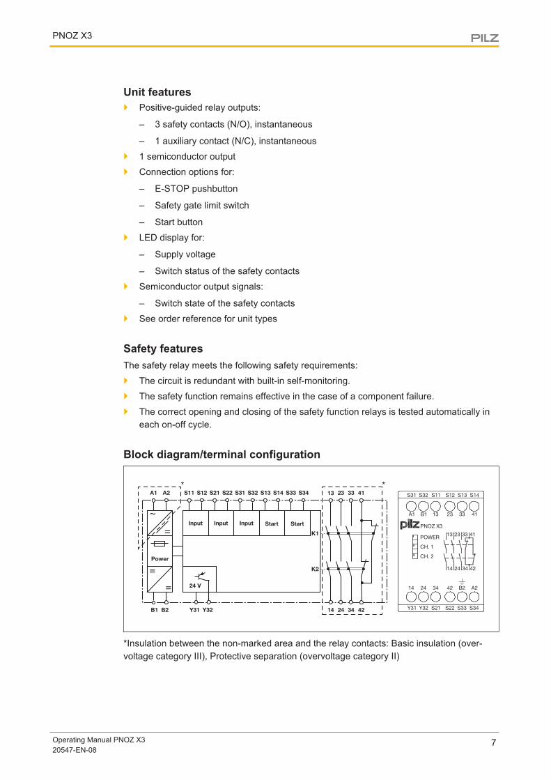
Block diagram/terminal configuration
* *
*Insulation between the non-marked area and the relay contacts: Basic insulation (over-voltage category III), Protective separation (overvoltage category II)
PNOZ X3
Operating Manual PNOZ X320547-EN-08
8
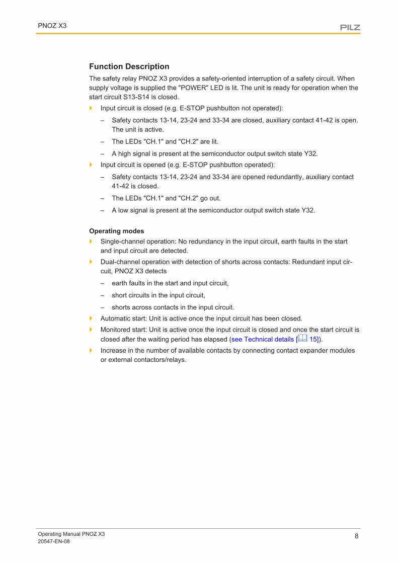
Function DescriptionThe safety relay PNOZ X3 provides a safety-oriented interruption of a safety circuit. Whensupply voltage is supplied the "POWER" LED is lit. The unit is ready for operation when thestart circuit S13-S14 is closed.
} Input circuit is closed (e.g. E-STOP pushbutton not operated):
– Safety contacts 13-14, 23-24 and 33-34 are closed, auxiliary contact 41-42 is open.The unit is active.
– The LEDs "CH.1" and "CH.2" are lit.
– A high signal is present at the semiconductor output switch state Y32.
} Input circuit is opened (e.g. E-STOP pushbutton operated):
– Safety contacts 13-14, 23-24 and 33-34 are opened redundantly, auxiliary contact41-42 is closed.
– The LEDs "CH.1" and "CH.2" go out.
– A low signal is present at the semiconductor output switch state Y32.
Operating modes} Single-channel operation: No redundancy in the input circuit, earth faults in the start
and input circuit are detected.
} Dual-channel operation with detection of shorts across contacts: Redundant input cir-cuit, PNOZ X3 detects
– earth faults in the start and input circuit,
– short circuits in the input circuit,
– shorts across contacts in the input circuit.
} Automatic start: Unit is active once the input circuit has been closed.
} Monitored start: Unit is active once the input circuit is closed and once the start circuit isclosed after the waiting period has elapsed (see Technical details [ 15]).
} Increase in the number of available contacts by connecting contact expander modulesor external contactors/relays.
PNOZ X3
Operating Manual PNOZ X320547-EN-08
9
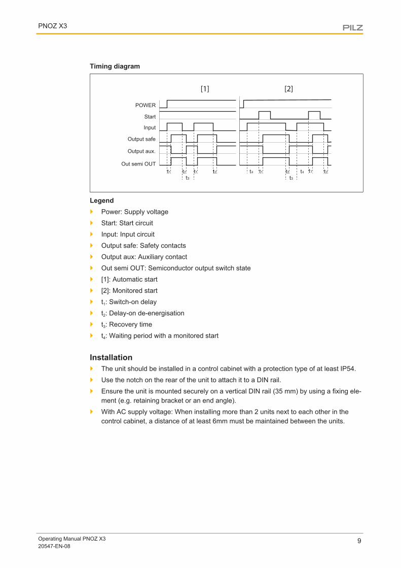
Timing diagram
[1] [2]
POWER
Start
Input
Output safe
Output aux.
Out semi OUT
Legend} Power: Supply voltage
} Start: Start circuit
} Input: Input circuit
} Output safe: Safety contacts
} Output aux: Auxiliary contact
} Out semi OUT: Semiconductor output switch state
} [1]: Automatic start
} [2]: Monitored start
} t1: Switch-on delay
} t2: Delay-on de-energisation
} t3: Recovery time
} t4: Waiting period with a monitored start
Installation} The unit should be installed in a control cabinet with a protection type of at least IP54.
} Use the notch on the rear of the unit to attach it to a DIN rail.
} Ensure the unit is mounted securely on a vertical DIN rail (35 mm) by using a fixing ele-ment (e.g. retaining bracket or an end angle).
} With AC supply voltage: When installing more than 2 units next to each other in thecontrol cabinet, a distance of at least 6mm must be maintained between the units.
PNOZ X3
Operating Manual PNOZ X320547-EN-08
10
WiringPlease note:
} Information given in the "Technical details [ 15]" must be followed.
} Outputs 13-14, 23-24, 33-34 are safety contacts; output 41-42 is an auxiliary contact(e.g. for display).
} Auxiliary contact 41-42 should not be used for safety circuits!
} Delivery condition: Link between S11-S12 (dual-channel input circuit)
} To prevent contact welding, a fuse should be connected before the output contacts (seeTechnical details [ 15]).
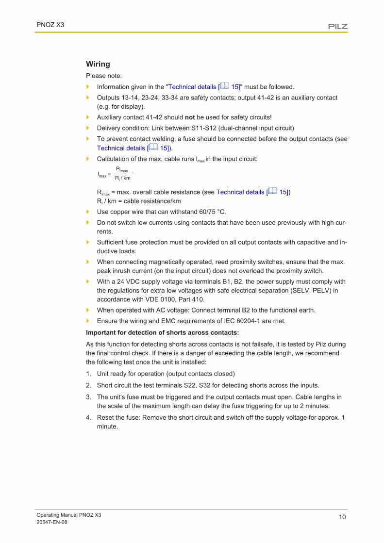
} Calculation of the max. cable runs lmax in the input circuit:R
lmax
Rl / km
Imax
=
Rlmax = max. overall cable resistance (see Technical details [ 15])Rl / km = cable resistance/km
} Use copper wire that can withstand 60/75 °C.
} Do not switch low currents using contacts that have been used previously with high cur-rents.
} Sufficient fuse protection must be provided on all output contacts with capacitive and in-ductive loads.
} When connecting magnetically operated, reed proximity switches, ensure that the max.peak inrush current (on the input circuit) does not overload the proximity switch.
} With a 24 VDC supply voltage via terminals B1, B2, the power supply must comply withthe regulations for extra low voltages with safe electrical separation (SELV, PELV) inaccordance with VDE 0100, Part 410.
} When operated with AC voltage: Connect terminal B2 to the functional earth.
} Ensure the wiring and EMC requirements of IEC 60204-1 are met.
Important for detection of shorts across contacts:
As this function for detecting shorts across contacts is not failsafe, it is tested by Pilz duringthe final control check. If there is a danger of exceeding the cable length, we recommendthe following test once the unit is installed:
1. Unit ready for operation (output contacts closed)
2. Short circuit the test terminals S22, S32 for detecting shorts across the inputs.
3. The unit‘s fuse must be triggered and the output contacts must open. Cable lengths inthe scale of the maximum length can delay the fuse triggering for up to 2 minutes.
4. Reset the fuse: Remove the short circuit and switch off the supply voltage for approx. 1minute.
PNOZ X3
Operating Manual PNOZ X320547-EN-08
11
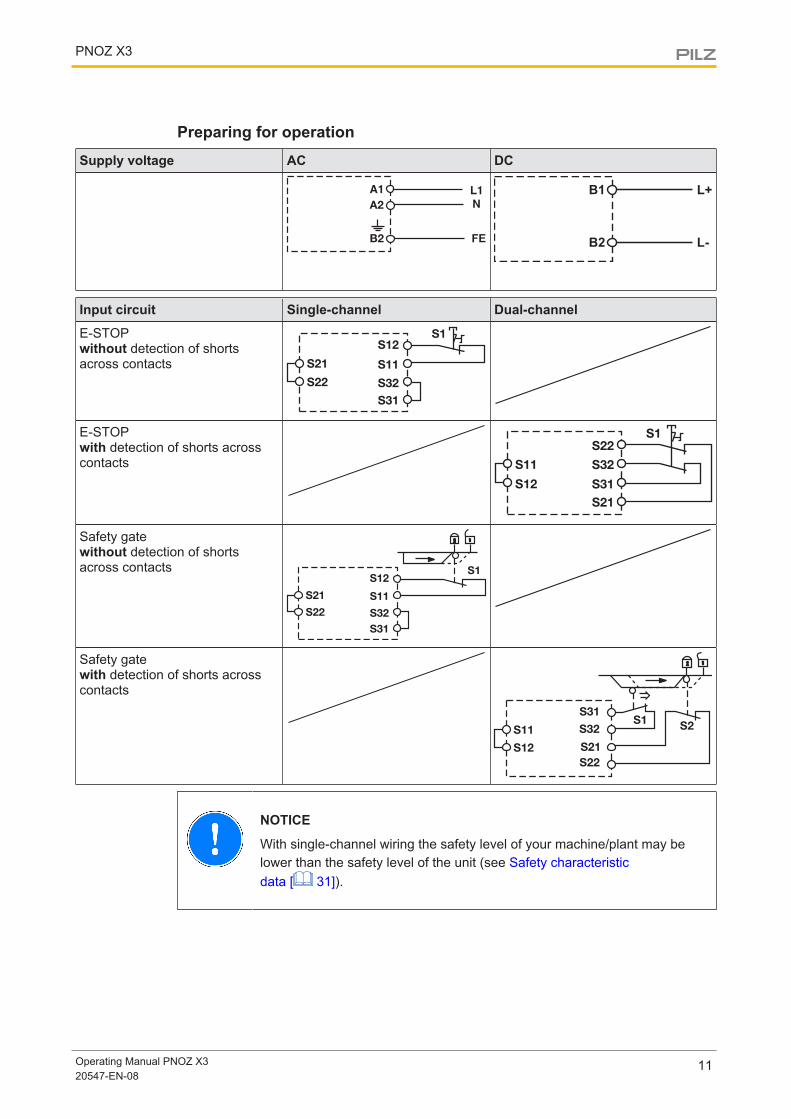
Preparing for operationSupply voltage AC DC
FE
B1
B2
L+
L-
Input circuit Single-channel Dual-channel
E-STOPwithout detection of shortsacross contacts
S1
S22
S21
S12
S32
S11
S31
E-STOPwith detection of shorts acrosscontacts
S1
S22
S31
S32
S21
S12
S11
Safety gatewithout detection of shortsacross contacts S1
S22
S21
S12
S32
S11
S31
Safety gatewith detection of shorts acrosscontacts
NOTICE
With single-channel wiring the safety level of your machine/plant may belower than the safety level of the unit (see Safety characteristicdata [ 31]).
PNOZ X3
Operating Manual PNOZ X320547-EN-08
12
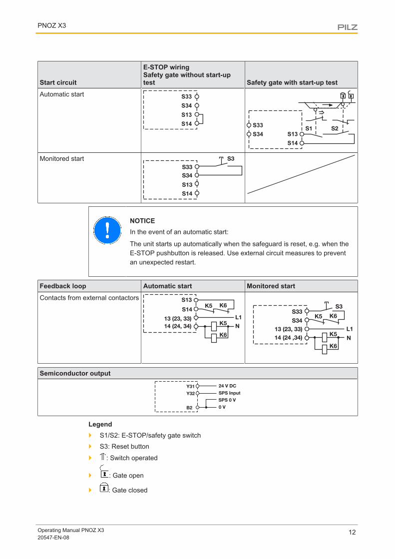
Start circuit
E-STOP wiringSafety gate without start-uptest Safety gate with start-up test
Automatic start S33
S34
S13
S14 S33
S13S34
S14
Monitored startS33
S34
S3
S14
S13
NOTICEIn the event of an automatic start:
The unit starts up automatically when the safeguard is reset, e.g. when theE-STOP pushbutton is released. Use external circuit measures to preventan unexpected restart.
Feedback loop Automatic start Monitored start
Contacts from external contactorsK5 K6
K5L1
N
K6
S13
13 (23, 33)
S14
14 (24, 34)
Semiconductor output
Legend} S1/S2: E-STOP/safety gate switch
} S3: Reset button
} : Switch operated
} : Gate open
} : Gate closed
PNOZ X3
Operating Manual PNOZ X320547-EN-08
13
INFORMATIONWith automatic start, S33 and S34 must not be linked; with monitored start,S13 and S14 must not be linked.
Operation
NOTICE
Check each safety function
– after initial commissioning and after each change of the machine/plant
– for SIL CL 3/PL e at least 1x per month, for SIL CL 2/PL d at least 1xper year
Follow the instructions below:
– Activate the safety function and check whether all the used safetycontacts open.
– Prepare for operation again and start the unit. All the used safetycontacts must be closed again.
The safety functions may only be checked by qualified personnel.
Status indicatorsLEDs indicate the status and errors during operation:
LED on
POWERSupply voltage is present.
CH.1 Safety contacts of channel 1 are closed.
CH.2 Safety contacts of channel 2 are closed.
PNOZ X3
Operating Manual PNOZ X320547-EN-08
14
Faults – Interference} Earth fault: The supply voltage fails and the safety contacts open. Once the cause of
the respective fault has been rectified and the supply voltage is switched off for approx.1 minute, the unit is ready for operation again.
} Contact malfunctions: If the contacts have welded, reactivation will not be possible afterthe input circuit has opened.
} LED "POWER" does not light: Short circuit or no supply voltage.
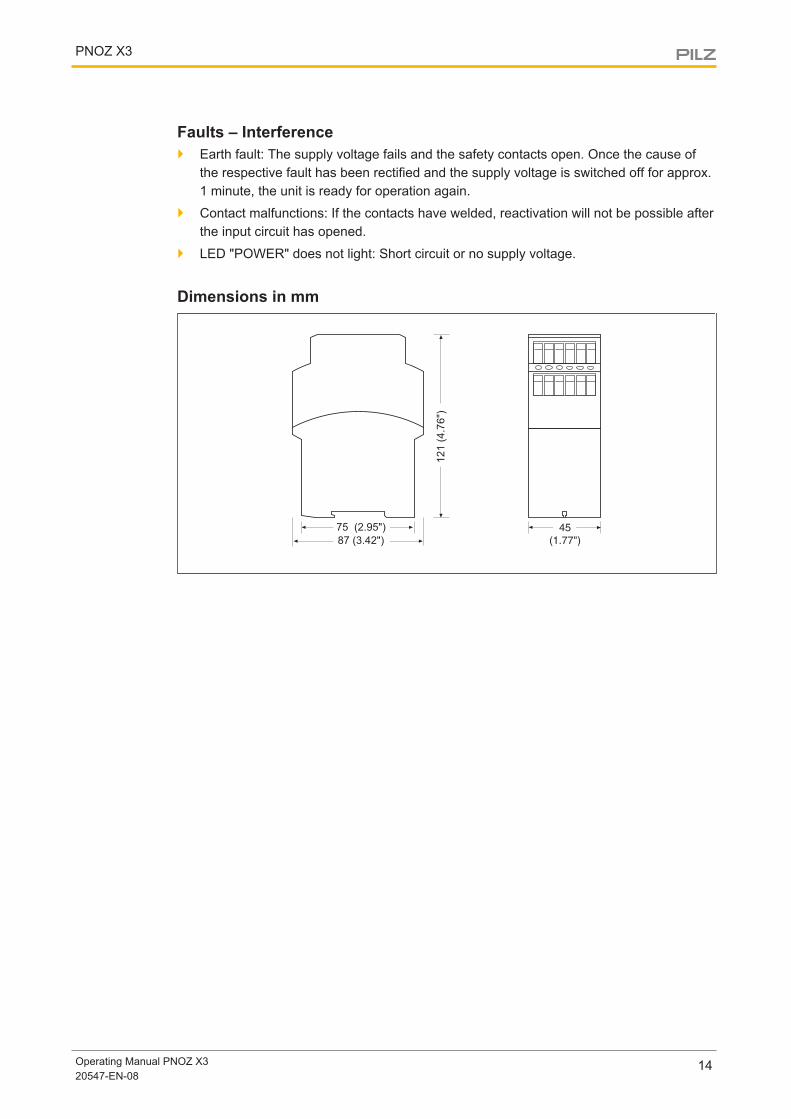
Dimensions in mm
121 (
4.7
6")
75 (2.95")
87 (3.42")
45
(1.77")
PNOZ X3
Operating Manual PNOZ X320547-EN-08
15
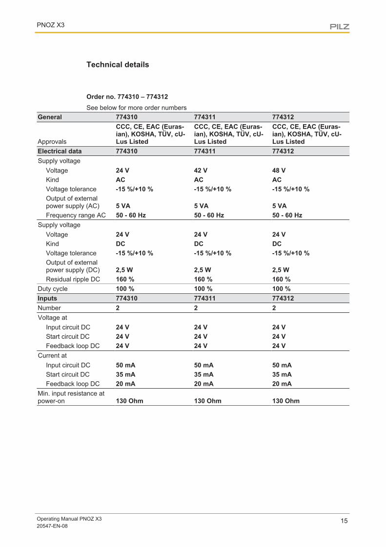
Technical details
Order no. 774310 – 774312See below for more order numbers
General 774310 774311 774312
Approvals
CCC, CE, EAC (Euras-ian), KOSHA, TÜV, cU-Lus Listed
CCC, CE, EAC (Euras-ian), KOSHA, TÜV, cU-Lus Listed
CCC, CE, EAC (Euras-ian), KOSHA, TÜV, cU-Lus Listed
Electrical data 774310 774311 774312Supply voltage
Voltage 24 V 42 V 48 VKind AC AC ACVoltage tolerance -15 %/+10 % -15 %/+10 % -15 %/+10 %Output of externalpower supply (AC) 5 VA 5 VA 5 VAFrequency range AC 50 - 60 Hz 50 - 60 Hz 50 - 60 Hz
Supply voltageVoltage 24 V 24 V 24 VKind DC DC DCVoltage tolerance -15 %/+10 % -15 %/+10 % -15 %/+10 %Output of externalpower supply (DC) 2,5 W 2,5 W 2,5 WResidual ripple DC 160 % 160 % 160 %
Duty cycle 100 % 100 % 100 %Inputs 774310 774311 774312Number 2 2 2Voltage at
Input circuit DC 24 V 24 V 24 VStart circuit DC 24 V 24 V 24 VFeedback loop DC 24 V 24 V 24 V
Current atInput circuit DC 50 mA 50 mA 50 mAStart circuit DC 35 mA 35 mA 35 mAFeedback loop DC 20 mA 20 mA 20 mA
Min. input resistance atpower-on 130 Ohm 130 Ohm 130 Ohm
PNOZ X3
Operating Manual PNOZ X320547-EN-08
16
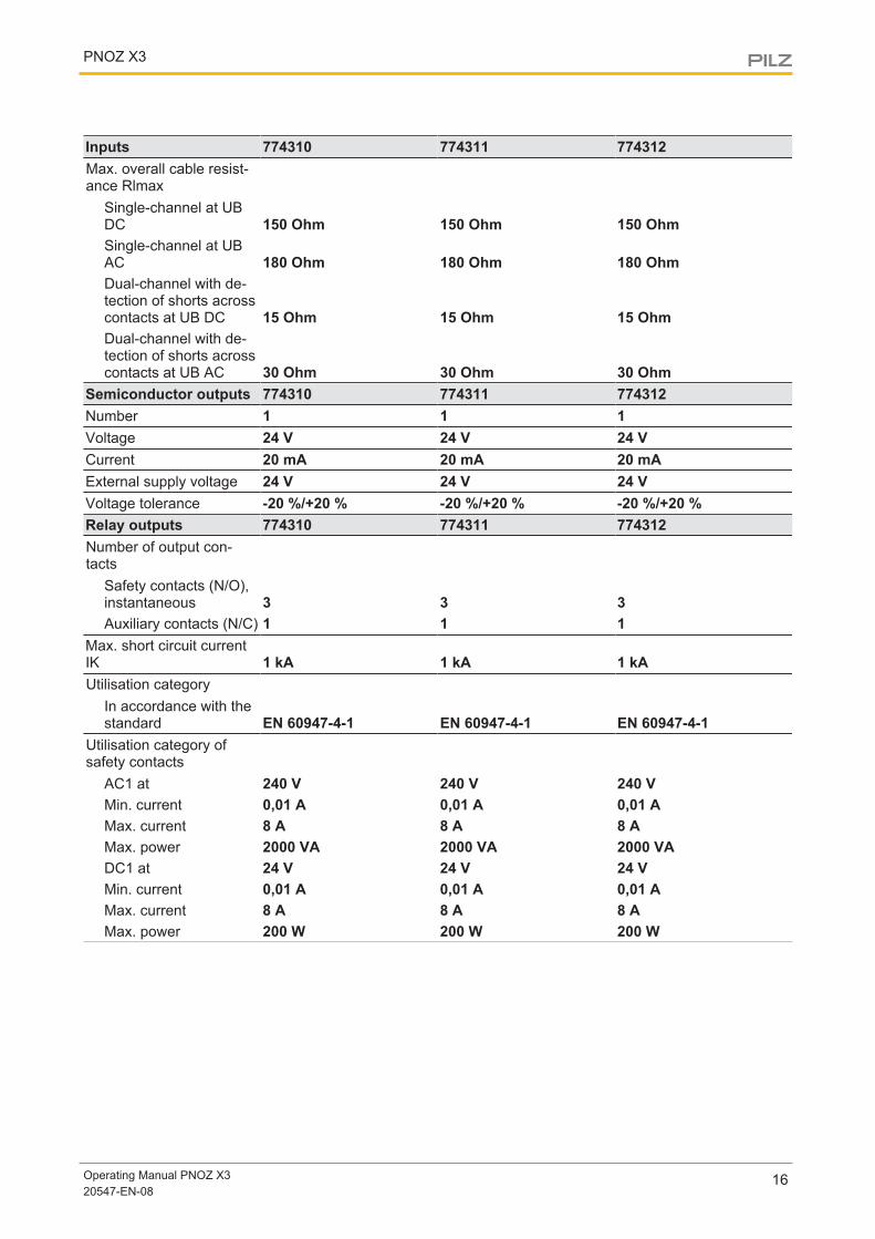
Inputs 774310 774311 774312Max. overall cable resist-ance Rlmax
Single-channel at UBDC 150 Ohm 150 Ohm 150 OhmSingle-channel at UBAC 180 Ohm 180 Ohm 180 OhmDual-channel with de-tection of shorts acrosscontacts at UB DC 15 Ohm 15 Ohm 15 OhmDual-channel with de-tection of shorts acrosscontacts at UB AC 30 Ohm 30 Ohm 30 Ohm
Semiconductor outputs 774310 774311 774312Number 1 1 1Voltage 24 V 24 V 24 VCurrent 20 mA 20 mA 20 mAExternal supply voltage 24 V 24 V 24 VVoltage tolerance -20 %/+20 % -20 %/+20 % -20 %/+20 %Relay outputs 774310 774311 774312Number of output con-tacts
Safety contacts (N/O),instantaneous 3 3 3Auxiliary contacts (N/C) 1 1 1
Max. short circuit currentIK 1 kA 1 kA 1 kAUtilisation category
In accordance with thestandard EN 60947-4-1 EN 60947-4-1 EN 60947-4-1
Utilisation category ofsafety contacts
AC1 at 240 V 240 V 240 VMin. current 0,01 A 0,01 A 0,01 AMax. current 8 A 8 A 8 AMax. power 2000 VA 2000 VA 2000 VADC1 at 24 V 24 V 24 VMin. current 0,01 A 0,01 A 0,01 AMax. current 8 A 8 A 8 AMax. power 200 W 200 W 200 W
PNOZ X3
Operating Manual PNOZ X320547-EN-08
17
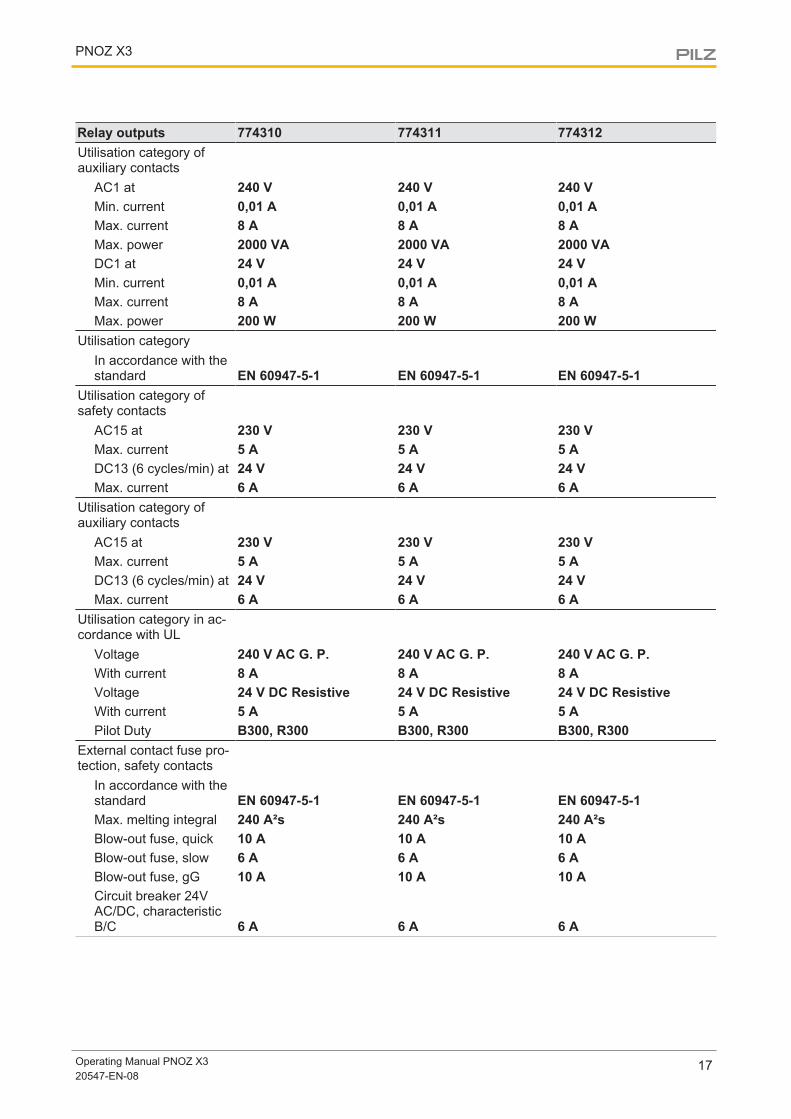
Relay outputs 774310 774311 774312Utilisation category ofauxiliary contacts
AC1 at 240 V 240 V 240 VMin. current 0,01 A 0,01 A 0,01 AMax. current 8 A 8 A 8 AMax. power 2000 VA 2000 VA 2000 VADC1 at 24 V 24 V 24 VMin. current 0,01 A 0,01 A 0,01 AMax. current 8 A 8 A 8 AMax. power 200 W 200 W 200 W
Utilisation categoryIn accordance with thestandard EN 60947-5-1 EN 60947-5-1 EN 60947-5-1
Utilisation category ofsafety contacts
AC15 at 230 V 230 V 230 VMax. current 5 A 5 A 5 ADC13 (6 cycles/min) at 24 V 24 V 24 VMax. current 6 A 6 A 6 A
Utilisation category ofauxiliary contacts
AC15 at 230 V 230 V 230 VMax. current 5 A 5 A 5 ADC13 (6 cycles/min) at 24 V 24 V 24 VMax. current 6 A 6 A 6 A
Utilisation category in ac-cordance with UL
Voltage 240 V AC G. P. 240 V AC G. P. 240 V AC G. P.With current 8 A 8 A 8 AVoltage 24 V DC Resistive 24 V DC Resistive 24 V DC ResistiveWith current 5 A 5 A 5 APilot Duty B300, R300 B300, R300 B300, R300
External contact fuse pro-tection, safety contacts
In accordance with thestandard EN 60947-5-1 EN 60947-5-1 EN 60947-5-1Max. melting integral 240 A²s 240 A²s 240 A²sBlow-out fuse, quick 10 A 10 A 10 ABlow-out fuse, slow 6 A 6 A 6 ABlow-out fuse, gG 10 A 10 A 10 ACircuit breaker 24VAC/DC, characteristicB/C 6 A 6 A 6 A
PNOZ X3
Operating Manual PNOZ X320547-EN-08
18
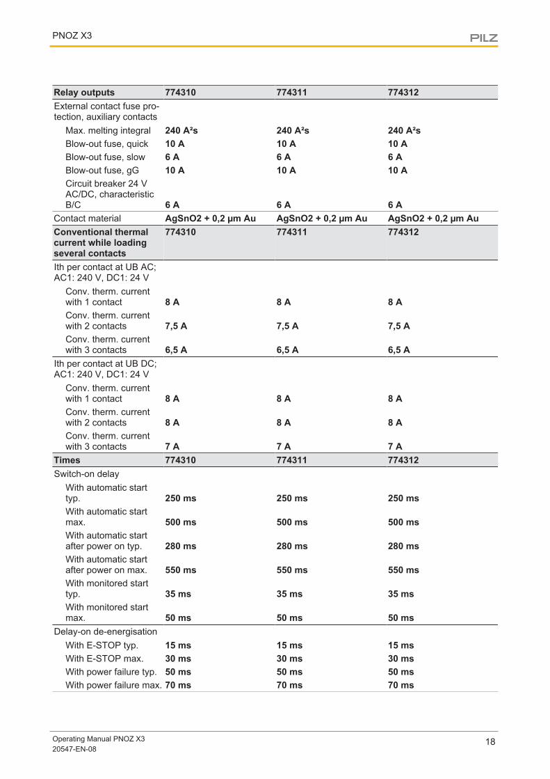
Relay outputs 774310 774311 774312External contact fuse pro-tection, auxiliary contacts
Max. melting integral 240 A²s 240 A²s 240 A²sBlow-out fuse, quick 10 A 10 A 10 ABlow-out fuse, slow 6 A 6 A 6 ABlow-out fuse, gG 10 A 10 A 10 ACircuit breaker 24 VAC/DC, characteristicB/C 6 A 6 A 6 A
Contact material AgSnO2 + 0,2 µm Au AgSnO2 + 0,2 µm Au AgSnO2 + 0,2 µm AuConventional thermalcurrent while loadingseveral contacts
774310 774311 774312
Ith per contact at UB AC;AC1: 240 V, DC1: 24 V
Conv. therm. currentwith 1 contact 8 A 8 A 8 AConv. therm. currentwith 2 contacts 7,5 A 7,5 A 7,5 AConv. therm. currentwith 3 contacts 6,5 A 6,5 A 6,5 A
Ith per contact at UB DC;AC1: 240 V, DC1: 24 V
Conv. therm. currentwith 1 contact 8 A 8 A 8 AConv. therm. currentwith 2 contacts 8 A 8 A 8 AConv. therm. currentwith 3 contacts 7 A 7 A 7 A
Times 774310 774311 774312Switch-on delay
With automatic starttyp. 250 ms 250 ms 250 msWith automatic startmax. 500 ms 500 ms 500 msWith automatic startafter power on typ. 280 ms 280 ms 280 msWith automatic startafter power on max. 550 ms 550 ms 550 msWith monitored starttyp. 35 ms 35 ms 35 msWith monitored startmax. 50 ms 50 ms 50 ms
Delay-on de-energisationWith E-STOP typ. 15 ms 15 ms 15 msWith E-STOP max. 30 ms 30 ms 30 msWith power failure typ. 50 ms 50 ms 50 msWith power failure max. 70 ms 70 ms 70 ms
PNOZ X3
Operating Manual PNOZ X320547-EN-08
19
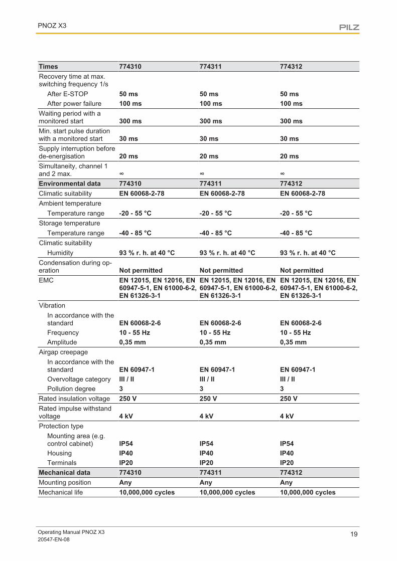
Times 774310 774311 774312Recovery time at max.switching frequency 1/s
After E-STOP 50 ms 50 ms 50 msAfter power failure 100 ms 100 ms 100 ms
Waiting period with amonitored start 300 ms 300 ms 300 msMin. start pulse durationwith a monitored start 30 ms 30 ms 30 msSupply interruption beforede-energisation 20 ms 20 ms 20 msSimultaneity, channel 1and 2 max. ∞ ∞ ∞Environmental data 774310 774311 774312Climatic suitability EN 60068-2-78 EN 60068-2-78 EN 60068-2-78Ambient temperature
Temperature range -20 - 55 °C -20 - 55 °C -20 - 55 °CStorage temperature
Temperature range -40 - 85 °C -40 - 85 °C -40 - 85 °CClimatic suitability
Humidity 93 % r. h. at 40 °C 93 % r. h. at 40 °C 93 % r. h. at 40 °CCondensation during op-eration Not permitted Not permitted Not permittedEMC EN 12015, EN 12016, EN
60947-5-1, EN 61000-6-2,EN 61326-3-1
EN 12015, EN 12016, EN60947-5-1, EN 61000-6-2,EN 61326-3-1
EN 12015, EN 12016, EN60947-5-1, EN 61000-6-2,EN 61326-3-1
VibrationIn accordance with thestandard EN 60068-2-6 EN 60068-2-6 EN 60068-2-6Frequency 10 - 55 Hz 10 - 55 Hz 10 - 55 HzAmplitude 0,35 mm 0,35 mm 0,35 mm
Airgap creepageIn accordance with thestandard EN 60947-1 EN 60947-1 EN 60947-1Overvoltage category III / II III / II III / IIPollution degree 3 3 3
Rated insulation voltage 250 V 250 V 250 VRated impulse withstandvoltage 4 kV 4 kV 4 kVProtection type
Mounting area (e.g.control cabinet) IP54 IP54 IP54Housing IP40 IP40 IP40Terminals IP20 IP20 IP20
Mechanical data 774310 774311 774312Mounting position Any Any AnyMechanical life 10,000,000 cycles 10,000,000 cycles 10,000,000 cycles
PNOZ X3
Operating Manual PNOZ X320547-EN-08
20
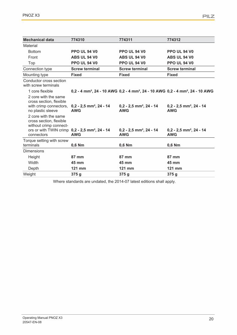
Mechanical data 774310 774311 774312Material
Bottom PPO UL 94 V0 PPO UL 94 V0 PPO UL 94 V0Front ABS UL 94 V0 ABS UL 94 V0 ABS UL 94 V0Top PPO UL 94 V0 PPO UL 94 V0 PPO UL 94 V0
Connection type Screw terminal Screw terminal Screw terminalMounting type Fixed Fixed FixedConductor cross sectionwith screw terminals
1 core flexible 0,2 - 4 mm², 24 - 10 AWG 0,2 - 4 mm², 24 - 10 AWG 0,2 - 4 mm², 24 - 10 AWG2 core with the samecross section, flexiblewith crimp connectors,no plastic sleeve
0,2 - 2,5 mm², 24 - 14AWG
0,2 - 2,5 mm², 24 - 14AWG
0,2 - 2,5 mm², 24 - 14AWG
2 core with the samecross section, flexiblewithout crimp connect-ors or with TWIN crimpconnectors
0,2 - 2,5 mm², 24 - 14AWG
0,2 - 2,5 mm², 24 - 14AWG
0,2 - 2,5 mm², 24 - 14AWG
Torque setting with screwterminals 0,6 Nm 0,6 Nm 0,6 NmDimensions
Height 87 mm 87 mm 87 mmWidth 45 mm 45 mm 45 mmDepth 121 mm 121 mm 121 mm
Weight 375 g 375 g 375 g
Where standards are undated, the 2014-07 latest editions shall apply.
PNOZ X3
Operating Manual PNOZ X320547-EN-08
21
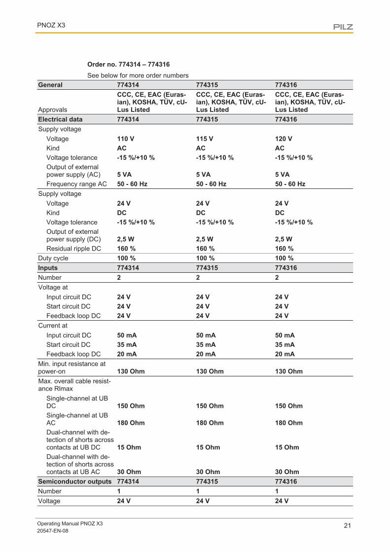
Order no. 774314 – 774316See below for more order numbers
General 774314 774315 774316
Approvals
CCC, CE, EAC (Euras-ian), KOSHA, TÜV, cU-Lus Listed
CCC, CE, EAC (Euras-ian), KOSHA, TÜV, cU-Lus Listed
CCC, CE, EAC (Euras-ian), KOSHA, TÜV, cU-Lus Listed
Electrical data 774314 774315 774316Supply voltage
Voltage 110 V 115 V 120 VKind AC AC ACVoltage tolerance -15 %/+10 % -15 %/+10 % -15 %/+10 %Output of externalpower supply (AC) 5 VA 5 VA 5 VAFrequency range AC 50 - 60 Hz 50 - 60 Hz 50 - 60 Hz
Supply voltageVoltage 24 V 24 V 24 VKind DC DC DCVoltage tolerance -15 %/+10 % -15 %/+10 % -15 %/+10 %Output of externalpower supply (DC) 2,5 W 2,5 W 2,5 WResidual ripple DC 160 % 160 % 160 %
Duty cycle 100 % 100 % 100 %Inputs 774314 774315 774316Number 2 2 2Voltage at
Input circuit DC 24 V 24 V 24 VStart circuit DC 24 V 24 V 24 VFeedback loop DC 24 V 24 V 24 V
Current atInput circuit DC 50 mA 50 mA 50 mAStart circuit DC 35 mA 35 mA 35 mAFeedback loop DC 20 mA 20 mA 20 mA
Min. input resistance atpower-on 130 Ohm 130 Ohm 130 OhmMax. overall cable resist-ance Rlmax
Single-channel at UBDC 150 Ohm 150 Ohm 150 OhmSingle-channel at UBAC 180 Ohm 180 Ohm 180 OhmDual-channel with de-tection of shorts acrosscontacts at UB DC 15 Ohm 15 Ohm 15 OhmDual-channel with de-tection of shorts acrosscontacts at UB AC 30 Ohm 30 Ohm 30 Ohm
Semiconductor outputs 774314 774315 774316Number 1 1 1Voltage 24 V 24 V 24 V
PNOZ X3
Operating Manual PNOZ X320547-EN-08
22
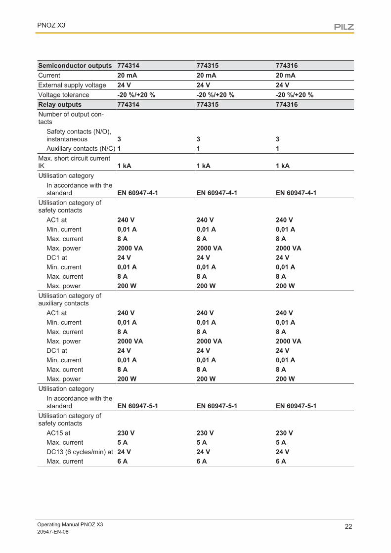
Semiconductor outputs 774314 774315 774316Current 20 mA 20 mA 20 mAExternal supply voltage 24 V 24 V 24 VVoltage tolerance -20 %/+20 % -20 %/+20 % -20 %/+20 %Relay outputs 774314 774315 774316Number of output con-tacts
Safety contacts (N/O),instantaneous 3 3 3Auxiliary contacts (N/C) 1 1 1
Max. short circuit currentIK 1 kA 1 kA 1 kAUtilisation category
In accordance with thestandard EN 60947-4-1 EN 60947-4-1 EN 60947-4-1
Utilisation category ofsafety contacts
AC1 at 240 V 240 V 240 VMin. current 0,01 A 0,01 A 0,01 AMax. current 8 A 8 A 8 AMax. power 2000 VA 2000 VA 2000 VADC1 at 24 V 24 V 24 VMin. current 0,01 A 0,01 A 0,01 AMax. current 8 A 8 A 8 AMax. power 200 W 200 W 200 W
Utilisation category ofauxiliary contacts
AC1 at 240 V 240 V 240 VMin. current 0,01 A 0,01 A 0,01 AMax. current 8 A 8 A 8 AMax. power 2000 VA 2000 VA 2000 VADC1 at 24 V 24 V 24 VMin. current 0,01 A 0,01 A 0,01 AMax. current 8 A 8 A 8 AMax. power 200 W 200 W 200 W
Utilisation categoryIn accordance with thestandard EN 60947-5-1 EN 60947-5-1 EN 60947-5-1
Utilisation category ofsafety contacts
AC15 at 230 V 230 V 230 VMax. current 5 A 5 A 5 ADC13 (6 cycles/min) at 24 V 24 V 24 VMax. current 6 A 6 A 6 A
PNOZ X3
Operating Manual PNOZ X320547-EN-08
23
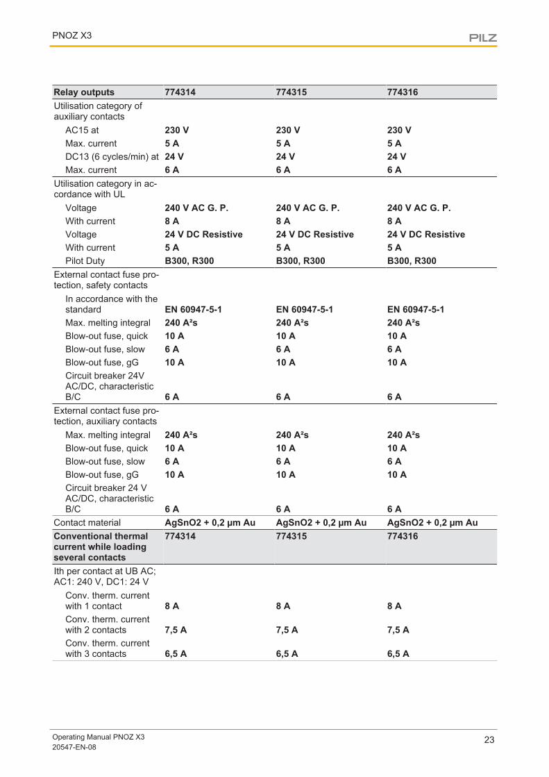
Relay outputs 774314 774315 774316Utilisation category ofauxiliary contacts
AC15 at 230 V 230 V 230 VMax. current 5 A 5 A 5 ADC13 (6 cycles/min) at 24 V 24 V 24 VMax. current 6 A 6 A 6 A
Utilisation category in ac-cordance with UL
Voltage 240 V AC G. P. 240 V AC G. P. 240 V AC G. P.With current 8 A 8 A 8 AVoltage 24 V DC Resistive 24 V DC Resistive 24 V DC ResistiveWith current 5 A 5 A 5 APilot Duty B300, R300 B300, R300 B300, R300
External contact fuse pro-tection, safety contacts
In accordance with thestandard EN 60947-5-1 EN 60947-5-1 EN 60947-5-1Max. melting integral 240 A²s 240 A²s 240 A²sBlow-out fuse, quick 10 A 10 A 10 ABlow-out fuse, slow 6 A 6 A 6 ABlow-out fuse, gG 10 A 10 A 10 ACircuit breaker 24VAC/DC, characteristicB/C 6 A 6 A 6 A
External contact fuse pro-tection, auxiliary contacts
Max. melting integral 240 A²s 240 A²s 240 A²sBlow-out fuse, quick 10 A 10 A 10 ABlow-out fuse, slow 6 A 6 A 6 ABlow-out fuse, gG 10 A 10 A 10 ACircuit breaker 24 VAC/DC, characteristicB/C 6 A 6 A 6 A
Contact material AgSnO2 + 0,2 µm Au AgSnO2 + 0,2 µm Au AgSnO2 + 0,2 µm AuConventional thermalcurrent while loadingseveral contacts
774314 774315 774316
Ith per contact at UB AC;AC1: 240 V, DC1: 24 V
Conv. therm. currentwith 1 contact 8 A 8 A 8 AConv. therm. currentwith 2 contacts 7,5 A 7,5 A 7,5 AConv. therm. currentwith 3 contacts 6,5 A 6,5 A 6,5 A
PNOZ X3
Operating Manual PNOZ X320547-EN-08
24
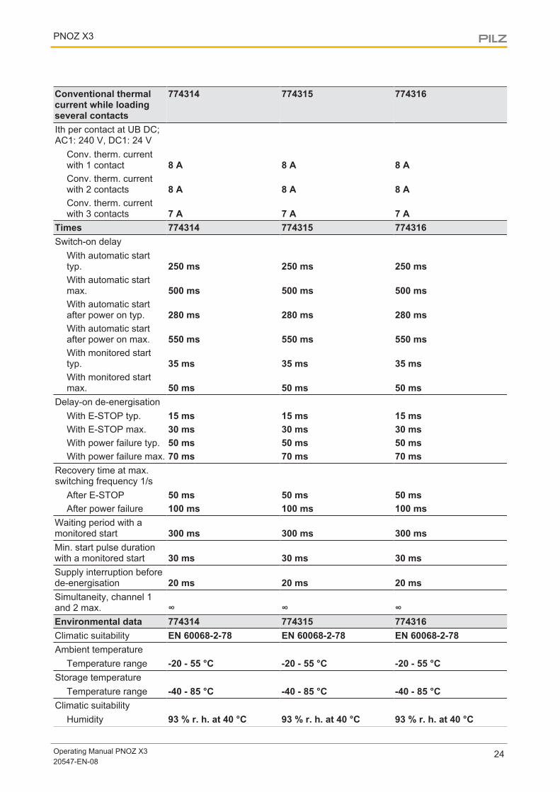
Conventional thermalcurrent while loadingseveral contacts
774314 774315 774316
Ith per contact at UB DC;AC1: 240 V, DC1: 24 V
Conv. therm. currentwith 1 contact 8 A 8 A 8 AConv. therm. currentwith 2 contacts 8 A 8 A 8 AConv. therm. currentwith 3 contacts 7 A 7 A 7 A
Times 774314 774315 774316Switch-on delay
With automatic starttyp. 250 ms 250 ms 250 msWith automatic startmax. 500 ms 500 ms 500 msWith automatic startafter power on typ. 280 ms 280 ms 280 msWith automatic startafter power on max. 550 ms 550 ms 550 msWith monitored starttyp. 35 ms 35 ms 35 msWith monitored startmax. 50 ms 50 ms 50 ms
Delay-on de-energisationWith E-STOP typ. 15 ms 15 ms 15 msWith E-STOP max. 30 ms 30 ms 30 msWith power failure typ. 50 ms 50 ms 50 msWith power failure max. 70 ms 70 ms 70 ms
Recovery time at max.switching frequency 1/s
After E-STOP 50 ms 50 ms 50 msAfter power failure 100 ms 100 ms 100 ms
Waiting period with amonitored start 300 ms 300 ms 300 msMin. start pulse durationwith a monitored start 30 ms 30 ms 30 msSupply interruption beforede-energisation 20 ms 20 ms 20 msSimultaneity, channel 1and 2 max. ∞ ∞ ∞Environmental data 774314 774315 774316Climatic suitability EN 60068-2-78 EN 60068-2-78 EN 60068-2-78Ambient temperature
Temperature range -20 - 55 °C -20 - 55 °C -20 - 55 °CStorage temperature
Temperature range -40 - 85 °C -40 - 85 °C -40 - 85 °CClimatic suitability
Humidity 93 % r. h. at 40 °C 93 % r. h. at 40 °C 93 % r. h. at 40 °C
PNOZ X3
Operating Manual PNOZ X320547-EN-08
25
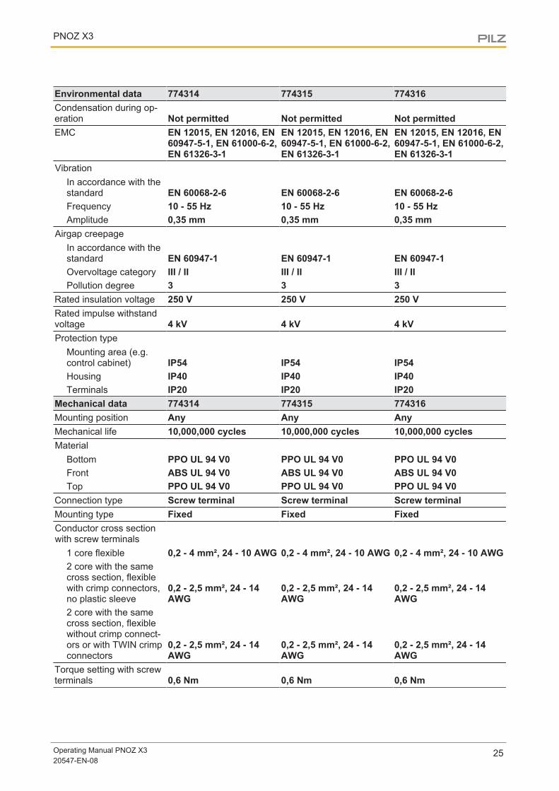
Environmental data 774314 774315 774316Condensation during op-eration Not permitted Not permitted Not permittedEMC EN 12015, EN 12016, EN
60947-5-1, EN 61000-6-2,EN 61326-3-1
EN 12015, EN 12016, EN60947-5-1, EN 61000-6-2,EN 61326-3-1
EN 12015, EN 12016, EN60947-5-1, EN 61000-6-2,EN 61326-3-1
VibrationIn accordance with thestandard EN 60068-2-6 EN 60068-2-6 EN 60068-2-6Frequency 10 - 55 Hz 10 - 55 Hz 10 - 55 HzAmplitude 0,35 mm 0,35 mm 0,35 mm
Airgap creepageIn accordance with thestandard EN 60947-1 EN 60947-1 EN 60947-1Overvoltage category III / II III / II III / IIPollution degree 3 3 3
Rated insulation voltage 250 V 250 V 250 VRated impulse withstandvoltage 4 kV 4 kV 4 kVProtection type
Mounting area (e.g.control cabinet) IP54 IP54 IP54Housing IP40 IP40 IP40Terminals IP20 IP20 IP20
Mechanical data 774314 774315 774316Mounting position Any Any AnyMechanical life 10,000,000 cycles 10,000,000 cycles 10,000,000 cyclesMaterial
Bottom PPO UL 94 V0 PPO UL 94 V0 PPO UL 94 V0Front ABS UL 94 V0 ABS UL 94 V0 ABS UL 94 V0Top PPO UL 94 V0 PPO UL 94 V0 PPO UL 94 V0
Connection type Screw terminal Screw terminal Screw terminalMounting type Fixed Fixed FixedConductor cross sectionwith screw terminals
1 core flexible 0,2 - 4 mm², 24 - 10 AWG 0,2 - 4 mm², 24 - 10 AWG 0,2 - 4 mm², 24 - 10 AWG2 core with the samecross section, flexiblewith crimp connectors,no plastic sleeve
0,2 - 2,5 mm², 24 - 14AWG
0,2 - 2,5 mm², 24 - 14AWG
0,2 - 2,5 mm², 24 - 14AWG
2 core with the samecross section, flexiblewithout crimp connect-ors or with TWIN crimpconnectors
0,2 - 2,5 mm², 24 - 14AWG
0,2 - 2,5 mm², 24 - 14AWG
0,2 - 2,5 mm², 24 - 14AWG
Torque setting with screwterminals 0,6 Nm 0,6 Nm 0,6 Nm
PNOZ X3
Operating Manual PNOZ X320547-EN-08
26
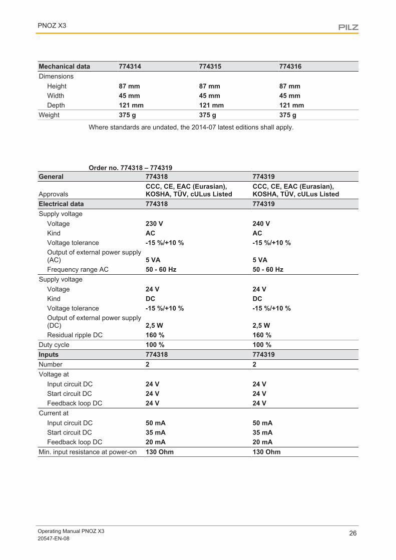
Mechanical data 774314 774315 774316Dimensions
Height 87 mm 87 mm 87 mmWidth 45 mm 45 mm 45 mmDepth 121 mm 121 mm 121 mm
Weight 375 g 375 g 375 g
Where standards are undated, the 2014-07 latest editions shall apply.
Order no. 774318 – 774319General 774318 774319
ApprovalsCCC, CE, EAC (Eurasian),KOSHA, TÜV, cULus Listed
CCC, CE, EAC (Eurasian),KOSHA, TÜV, cULus Listed
Electrical data 774318 774319Supply voltage
Voltage 230 V 240 VKind AC ACVoltage tolerance -15 %/+10 % -15 %/+10 %Output of external power supply(AC) 5 VA 5 VAFrequency range AC 50 - 60 Hz 50 - 60 Hz
Supply voltageVoltage 24 V 24 VKind DC DCVoltage tolerance -15 %/+10 % -15 %/+10 %Output of external power supply(DC) 2,5 W 2,5 WResidual ripple DC 160 % 160 %
Duty cycle 100 % 100 %Inputs 774318 774319Number 2 2Voltage at
Input circuit DC 24 V 24 VStart circuit DC 24 V 24 VFeedback loop DC 24 V 24 V
Current atInput circuit DC 50 mA 50 mAStart circuit DC 35 mA 35 mAFeedback loop DC 20 mA 20 mA
Min. input resistance at power-on 130 Ohm 130 Ohm
PNOZ X3
Operating Manual PNOZ X320547-EN-08
27
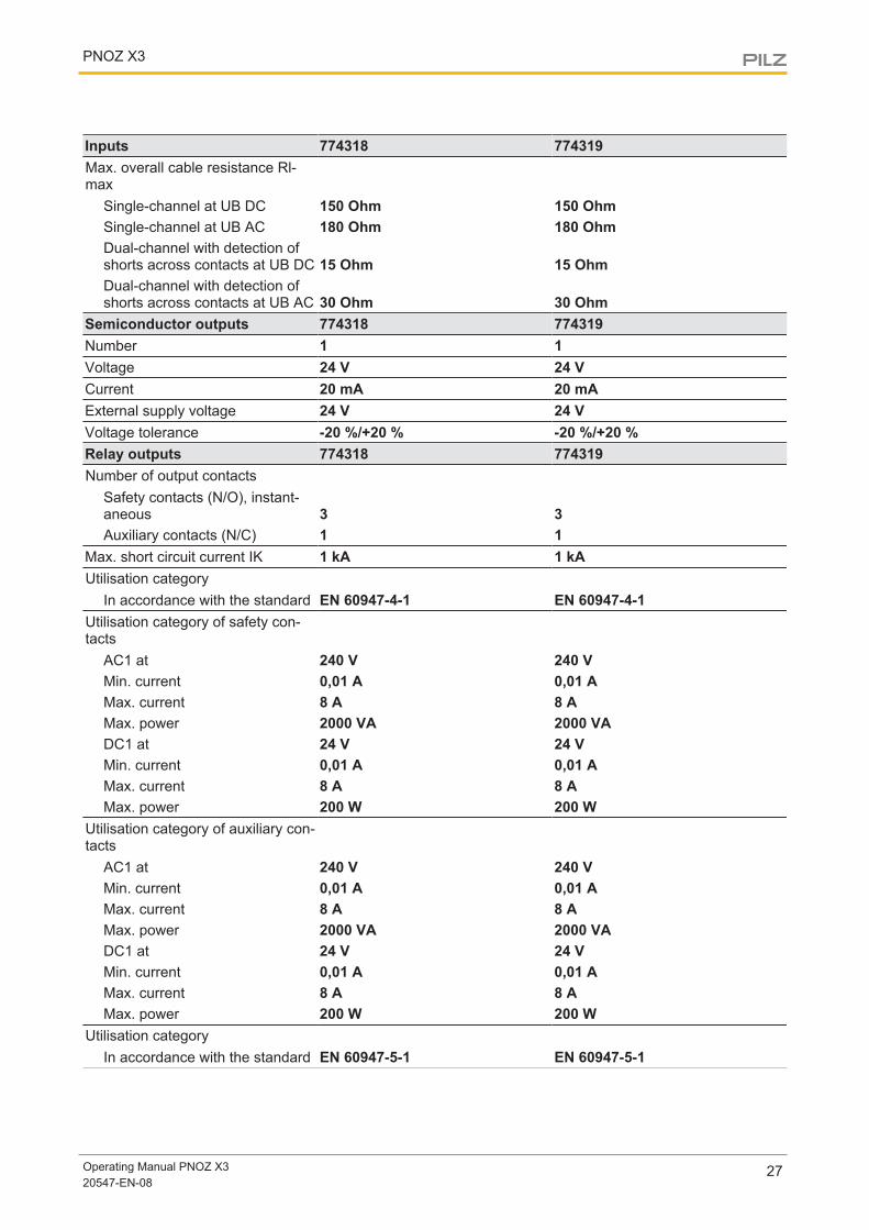
Inputs 774318 774319Max. overall cable resistance Rl-max
Single-channel at UB DC 150 Ohm 150 OhmSingle-channel at UB AC 180 Ohm 180 OhmDual-channel with detection ofshorts across contacts at UB DC 15 Ohm 15 OhmDual-channel with detection ofshorts across contacts at UB AC 30 Ohm 30 Ohm
Semiconductor outputs 774318 774319Number 1 1Voltage 24 V 24 VCurrent 20 mA 20 mAExternal supply voltage 24 V 24 VVoltage tolerance -20 %/+20 % -20 %/+20 %Relay outputs 774318 774319Number of output contacts
Safety contacts (N/O), instant-aneous 3 3Auxiliary contacts (N/C) 1 1
Max. short circuit current IK 1 kA 1 kAUtilisation category
In accordance with the standard EN 60947-4-1 EN 60947-4-1Utilisation category of safety con-tacts
AC1 at 240 V 240 VMin. current 0,01 A 0,01 AMax. current 8 A 8 AMax. power 2000 VA 2000 VADC1 at 24 V 24 VMin. current 0,01 A 0,01 AMax. current 8 A 8 AMax. power 200 W 200 W
Utilisation category of auxiliary con-tacts
AC1 at 240 V 240 VMin. current 0,01 A 0,01 AMax. current 8 A 8 AMax. power 2000 VA 2000 VADC1 at 24 V 24 VMin. current 0,01 A 0,01 AMax. current 8 A 8 AMax. power 200 W 200 W
Utilisation categoryIn accordance with the standard EN 60947-5-1 EN 60947-5-1
PNOZ X3
Operating Manual PNOZ X320547-EN-08
28
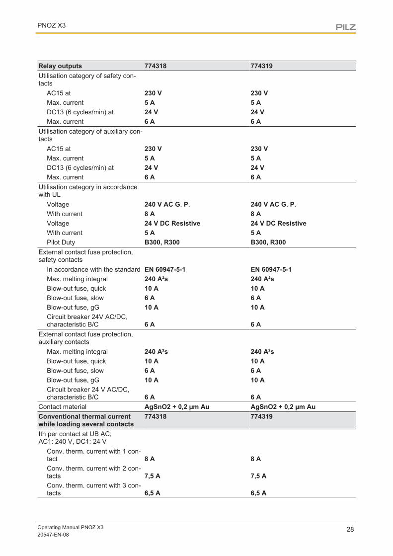
Relay outputs 774318 774319Utilisation category of safety con-tacts
AC15 at 230 V 230 VMax. current 5 A 5 ADC13 (6 cycles/min) at 24 V 24 VMax. current 6 A 6 A
Utilisation category of auxiliary con-tacts
AC15 at 230 V 230 VMax. current 5 A 5 ADC13 (6 cycles/min) at 24 V 24 VMax. current 6 A 6 A
Utilisation category in accordancewith UL
Voltage 240 V AC G. P. 240 V AC G. P.With current 8 A 8 AVoltage 24 V DC Resistive 24 V DC ResistiveWith current 5 A 5 APilot Duty B300, R300 B300, R300
External contact fuse protection,safety contacts
In accordance with the standard EN 60947-5-1 EN 60947-5-1Max. melting integral 240 A²s 240 A²sBlow-out fuse, quick 10 A 10 ABlow-out fuse, slow 6 A 6 ABlow-out fuse, gG 10 A 10 ACircuit breaker 24V AC/DC,characteristic B/C 6 A 6 A
External contact fuse protection,auxiliary contacts
Max. melting integral 240 A²s 240 A²sBlow-out fuse, quick 10 A 10 ABlow-out fuse, slow 6 A 6 ABlow-out fuse, gG 10 A 10 ACircuit breaker 24 V AC/DC,characteristic B/C 6 A 6 A
Contact material AgSnO2 + 0,2 µm Au AgSnO2 + 0,2 µm AuConventional thermal currentwhile loading several contacts
774318 774319
Ith per contact at UB AC;AC1: 240 V, DC1: 24 V
Conv. therm. current with 1 con-tact 8 A 8 AConv. therm. current with 2 con-tacts 7,5 A 7,5 AConv. therm. current with 3 con-tacts 6,5 A 6,5 A
PNOZ X3
Operating Manual PNOZ X320547-EN-08
29
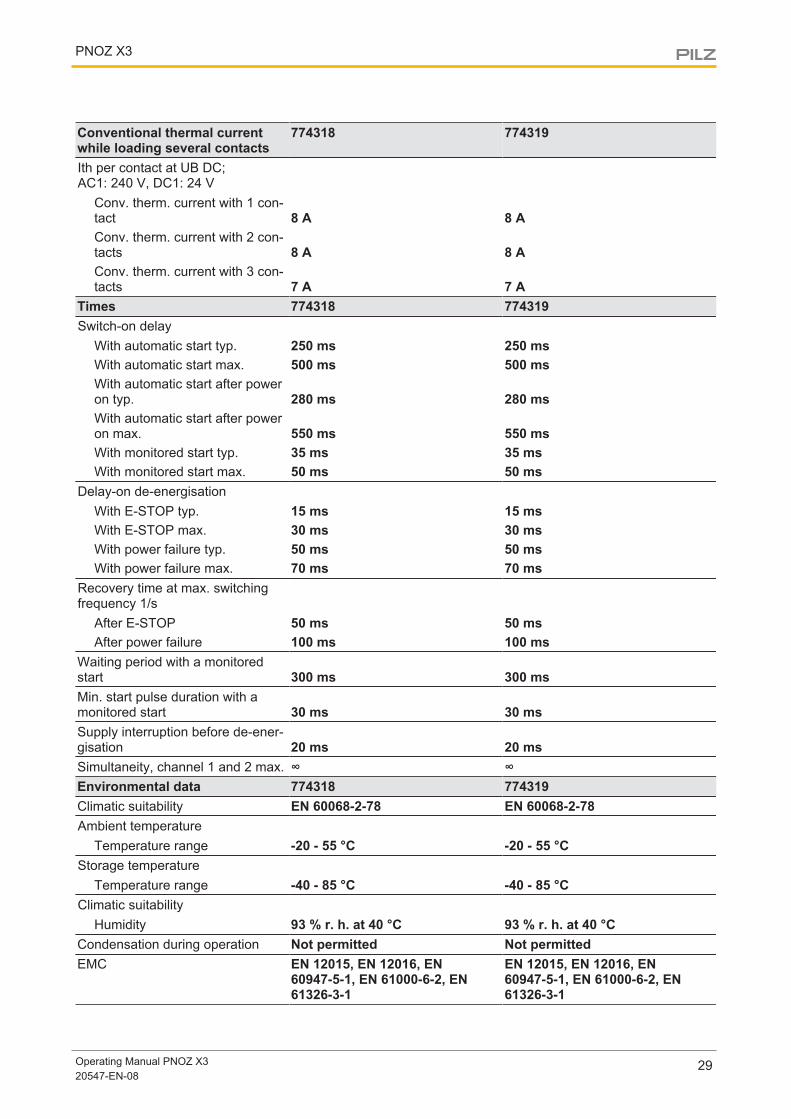
Conventional thermal currentwhile loading several contacts
774318 774319
Ith per contact at UB DC;AC1: 240 V, DC1: 24 V
Conv. therm. current with 1 con-tact 8 A 8 AConv. therm. current with 2 con-tacts 8 A 8 AConv. therm. current with 3 con-tacts 7 A 7 A
Times 774318 774319Switch-on delay
With automatic start typ. 250 ms 250 msWith automatic start max. 500 ms 500 msWith automatic start after poweron typ. 280 ms 280 msWith automatic start after poweron max. 550 ms 550 msWith monitored start typ. 35 ms 35 msWith monitored start max. 50 ms 50 ms
Delay-on de-energisationWith E-STOP typ. 15 ms 15 msWith E-STOP max. 30 ms 30 msWith power failure typ. 50 ms 50 msWith power failure max. 70 ms 70 ms
Recovery time at max. switchingfrequency 1/s
After E-STOP 50 ms 50 msAfter power failure 100 ms 100 ms
Waiting period with a monitoredstart 300 ms 300 msMin. start pulse duration with amonitored start 30 ms 30 msSupply interruption before de-ener-gisation 20 ms 20 msSimultaneity, channel 1 and 2 max. ∞ ∞Environmental data 774318 774319Climatic suitability EN 60068-2-78 EN 60068-2-78Ambient temperature
Temperature range -20 - 55 °C -20 - 55 °CStorage temperature
Temperature range -40 - 85 °C -40 - 85 °CClimatic suitability
Humidity 93 % r. h. at 40 °C 93 % r. h. at 40 °CCondensation during operation Not permitted Not permittedEMC EN 12015, EN 12016, EN
60947-5-1, EN 61000-6-2, EN61326-3-1
EN 12015, EN 12016, EN60947-5-1, EN 61000-6-2, EN61326-3-1
PNOZ X3
Operating Manual PNOZ X320547-EN-08
30
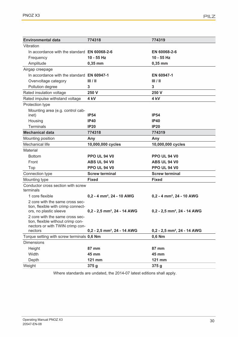
Environmental data 774318 774319Vibration
In accordance with the standard EN 60068-2-6 EN 60068-2-6Frequency 10 - 55 Hz 10 - 55 HzAmplitude 0,35 mm 0,35 mm
Airgap creepageIn accordance with the standard EN 60947-1 EN 60947-1Overvoltage category III / II III / IIPollution degree 3 3
Rated insulation voltage 250 V 250 VRated impulse withstand voltage 4 kV 4 kVProtection type
Mounting area (e.g. control cab-inet) IP54 IP54Housing IP40 IP40Terminals IP20 IP20
Mechanical data 774318 774319Mounting position Any AnyMechanical life 10,000,000 cycles 10,000,000 cyclesMaterial
Bottom PPO UL 94 V0 PPO UL 94 V0Front ABS UL 94 V0 ABS UL 94 V0Top PPO UL 94 V0 PPO UL 94 V0
Connection type Screw terminal Screw terminalMounting type Fixed FixedConductor cross section with screwterminals
1 core flexible 0,2 - 4 mm², 24 - 10 AWG 0,2 - 4 mm², 24 - 10 AWG2 core with the same cross sec-tion, flexible with crimp connect-ors, no plastic sleeve 0,2 - 2,5 mm², 24 - 14 AWG 0,2 - 2,5 mm², 24 - 14 AWG2 core with the same cross sec-tion, flexible without crimp con-nectors or with TWIN crimp con-nectors 0,2 - 2,5 mm², 24 - 14 AWG 0,2 - 2,5 mm², 24 - 14 AWG
Torque setting with screw terminals 0,6 Nm 0,6 NmDimensions
Height 87 mm 87 mmWidth 45 mm 45 mmDepth 121 mm 121 mm
Weight 375 g 375 g
Where standards are undated, the 2014-07 latest editions shall apply.
PNOZ X3
Operating Manual PNOZ X320547-EN-08
31
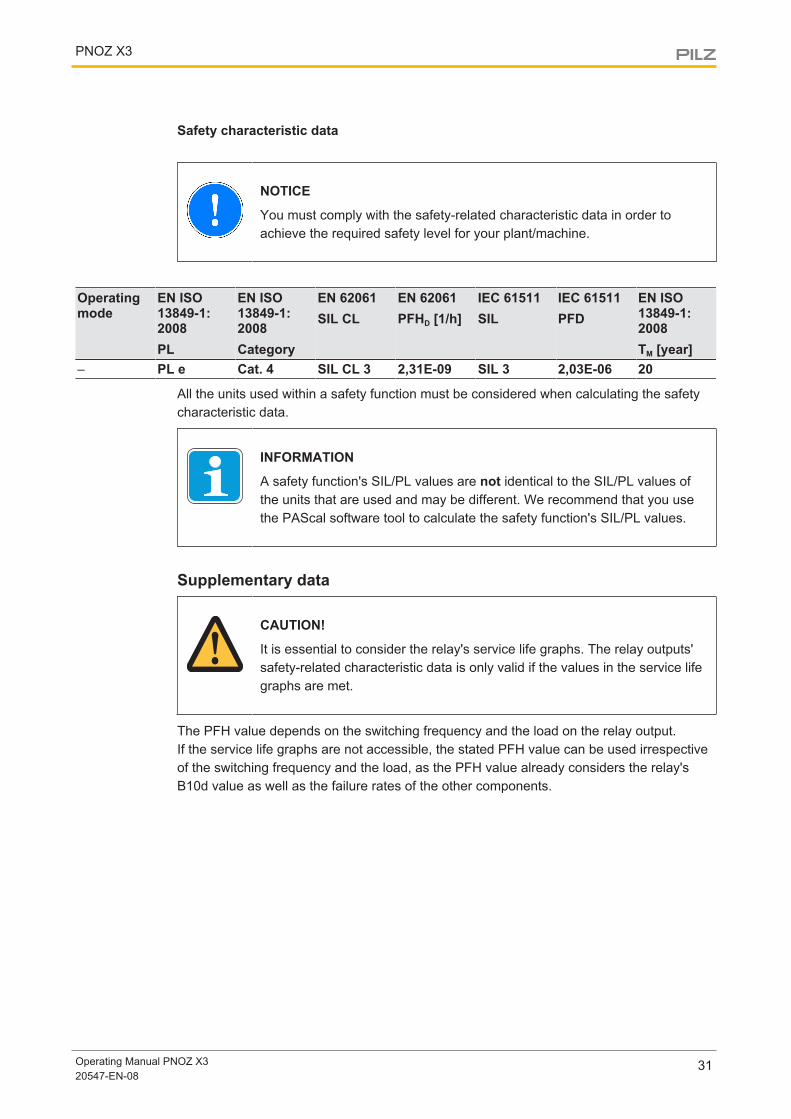
Safety characteristic data
NOTICE
You must comply with the safety-related characteristic data in order toachieve the required safety level for your plant/machine.
Operatingmode
EN ISO13849-1:2008PL
EN ISO13849-1:2008Category
EN 62061SIL CL
EN 62061PFHD [1/h]
IEC 61511SIL
IEC 61511PFD
EN ISO13849-1:2008TM [year]
– PL e Cat. 4 SIL CL 3 2,31E-09 SIL 3 2,03E-06 20
All the units used within a safety function must be considered when calculating the safetycharacteristic data.
INFORMATION
A safety function's SIL/PL values are not identical to the SIL/PL values ofthe units that are used and may be different. We recommend that you usethe PAScal software tool to calculate the safety function's SIL/PL values.
Supplementary data
CAUTION!
It is essential to consider the relay's service life graphs. The relay outputs'safety-related characteristic data is only valid if the values in the service lifegraphs are met.
The PFH value depends on the switching frequency and the load on the relay output.If the service life graphs are not accessible, the stated PFH value can be used irrespectiveof the switching frequency and the load, as the PFH value already considers the relay'sB10d value as well as the failure rates of the other components.
PNOZ X3
Operating Manual PNOZ X320547-EN-08
32
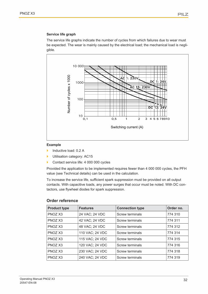
Service life graphThe service life graphs indicate the number of cycles from which failures due to wear mustbe expected. The wear is mainly caused by the electrical load; the mechanical load is negli-gible.
Num
ber o
f cyc
les
x 10
00
Switching current (A)
Example} Inductive load: 0.2 A
} Utilisation category: AC15
} Contact service life: 4 000 000 cycles
Provided the application to be implemented requires fewer than 4 000 000 cycles, the PFHvalue (see Technical details) can be used in the calculation.
To increase the service life, sufficient spark suppression must be provided on all outputcontacts. With capacitive loads, any power surges that occur must be noted. With DC con-tactors, use flywheel diodes for spark suppression.
Order referenceProduct type Features Connection type Order no.
PNOZ X3 24 VAC; 24 VDC Screw terminals 774 310
PNOZ X3 42 VAC; 24 VDC Screw terminals 774 311
PNOZ X3 48 VAC; 24 VDC Screw terminals 774 312
PNOZ X3 110 VAC; 24 VDC Screw terminals 774 314
PNOZ X3 115 VAC; 24 VDC Screw terminals 774 315
PNOZ X3 120 VAC; 24 VDC Screw terminals 774 316
PNOZ X3 230 VAC; 24 VDC Screw terminals 774 318
PNOZ X3 240 VAC; 24 VDC Screw terminals 774 319
PNOZ X3
Operating Manual PNOZ X320547-EN-08
33
EC declaration of conformityThis product/these products meet the requirements of the directive 2006/42/EC for ma-chinery of the European Parliament and of the Council. The complete EC Declaration ofConformity is available on the Internet at www.pilz.com/support/downloads.Representative: Norbert Fröhlich, Pilz GmbH & Co. KG, Felix-Wankel-Str. 2, 73760 Ost-fildern, Germany
The Best of German Engineering
Partner of:
SupportTechnical support is available from Pilz round the clock.
Americas
Brazil
+55 11 97569-2804
Canada
+1 888-315-PILZ (315-7459)
Mexico
+52 55 5572 1300
USA (toll-free)
+1 877-PILZUSA (745-9872)
Asia
China
+86 21 60880878-216
Japan
+81 45 471-2281
South Korea
+82 31 450 0680
Australia
+61 3 95446300
Europe
Austria
+43 1 7986263-0
Belgium, Luxembourg
+32 9 3217575
France
+33 3 88104000
Germany
+49 711 3409-444
Ireland
+353 21 4804983
Italy
+39 0362 1826711
Scandinavia
+45 74436332
Spain
+34 938497433
Switzerland
+41 62 88979-30
The Netherlands
+31 347 320477
Turkey
+90 216 5775552
United Kingdom
+44 1536 462203
You can reach our
international hotline on:
+49 711 3409-444
CM
SE®
, Ind
uraN
ET p
®, P
AS
4000
®, P
AS
cal®
, PA
Sco
nfig®
, Pilz
®, P
IT®, P
LID
®, P
MC
prim
o®, P
MC
prot
ego®
, PM
Cte
ndo®
, PM
D®, P
MI®
, PN
OZ®
, Prim
o®, P
SEN
®, P
SS
®, P
VIS
®, S
afet
yBU
S p
®,
Saf
etyE
YE®
, Saf
etyN
ET p
®, T
hE
SP
IrIT
Of
SA
fETY
® a
re re
gist
ered
and
pro
tect
ed tr
adem
arks
of P
ilz G
mbh
& C
o. K
G in
som
e co
untr
ies.
We
wou
ld p
oint
out
that
pro
duct
feat
ures
may
var
y
from
the
deta
ils s
tate
d in
this
doc
umen
t, de
pend
ing
on th
e st
atus
at t
he ti
me
of p
ublic
atio
n an
d th
e sc
ope
of th
e eq
uipm
ent.
We
acce
pt n
o re
spon
sibi
lity
for
the
valid
ity, a
ccur
acy
an
d en
tiret
y of
the
text
and
gra
phic
s pr
esen
ted
in th
is in
form
atio
n. P
leas
e co
ntac
t our
Tec
hnic
al S
uppo
rt if
you
hav
e an
y qu
estio
ns.
Pilz develops environmentally-friendly products using
ecological materials and energy-saving technologies.
Offices and production facilities are ecologically designed,
environmentally-aware and energy-saving. So Pilz offers
sustainability, plus the security of using energy-efficient
products and environmentally-friendly solutions.
Pilz Gmbh & Co. KG
felix-Wankel-Straße 2
73760 Ostfildern, Germany
Tel.: +49 711 3409-0
fax: +49 711 3409-133
www.pilz.com
100X
XXX-
DE-
0X0-
0-1-
3-00
0, 2
015-
00 P
rinte
d in
Ger
man
y©
Pilz
Gm
bh &
Co.
KG
, 201
5
2054
7-E
N-0
8, 2
016-
05 P
rinte
d in
Ger
man
y©
Pilz
Gm
bH &
Co.
KG
, 201
5
Back cover