Embed Size (px)
Citation preview

PNOZ m B0
Operating Manual 1002660-EN-05
} Configurable control systems PNOZmulti 2

PrefaceThis document is a translation of the original document.
All rights to this documentation are reserved by Pilz GmbH & Co. KG. Copies may be madefor internal purposes. Suggestions and comments for improving this documentation will begratefully received.
Pilz®, PIT®, PMI®, PNOZ®, Primo®, PSEN®, PSS®, PVIS®, SafetyBUS p®,SafetyEYE®, SafetyNET p®, the spirit of safety® are registered and protected trademarksof Pilz GmbH & Co. KG in some countries.
SD means Secure Digital
Contents
Operating Manual PNOZ m B01002660-EN-05
3
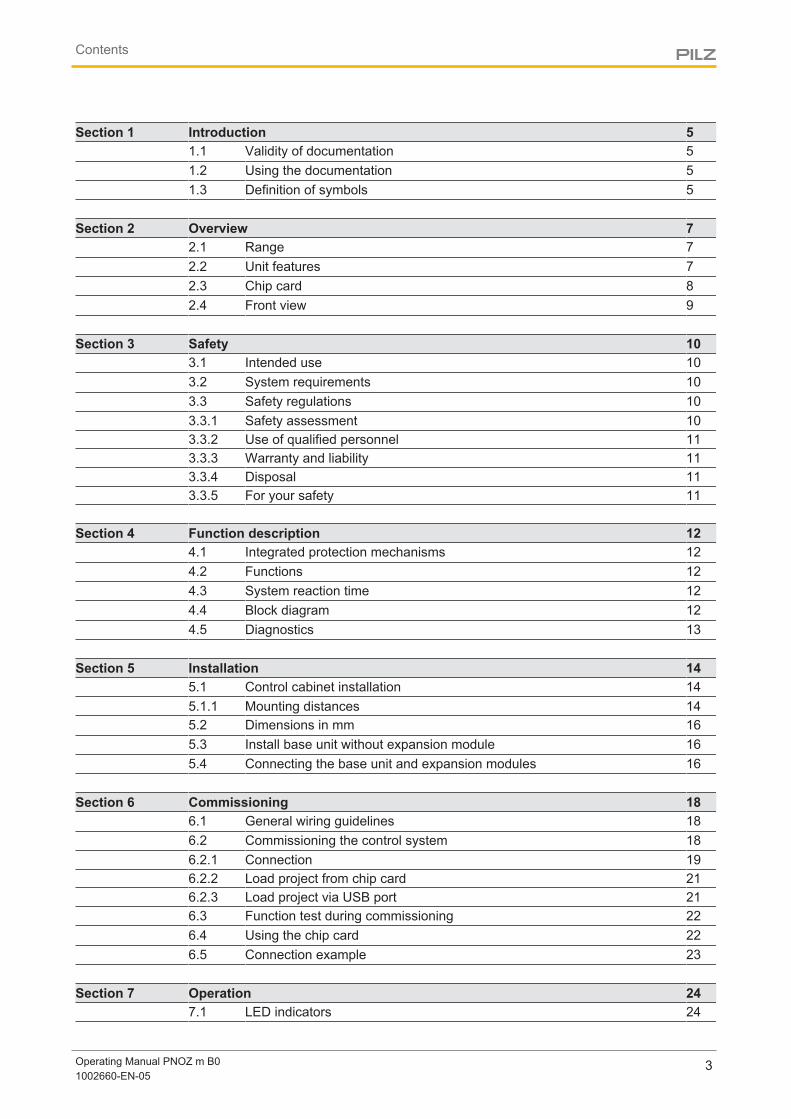
Section 1 Introduction 51.1 Validity of documentation 51.2 Using the documentation 51.3 Definition of symbols 5
Section 2 Overview 72.1 Range 72.2 Unit features 72.3 Chip card 82.4 Front view 9
Section 3 Safety 103.1 Intended use 103.2 System requirements 103.3 Safety regulations 103.3.1 Safety assessment 103.3.2 Use of qualified personnel 113.3.3 Warranty and liability 113.3.4 Disposal 113.3.5 For your safety 11
Section 4 Function description 124.1 Integrated protection mechanisms 124.2 Functions 124.3 System reaction time 124.4 Block diagram 124.5 Diagnostics 13
Section 5 Installation 145.1 Control cabinet installation 145.1.1 Mounting distances 145.2 Dimensions in mm 165.3 Install base unit without expansion module 165.4 Connecting the base unit and expansion modules 16
Section 6 Commissioning 186.1 General wiring guidelines 186.2 Commissioning the control system 186.2.1 Connection 196.2.2 Load project from chip card 216.2.3 Load project via USB port 216.3 Function test during commissioning 226.4 Using the chip card 226.5 Connection example 23
Section 7 Operation 247.1 LED indicators 24
Contents
Operating Manual PNOZ m B01002660-EN-05
4
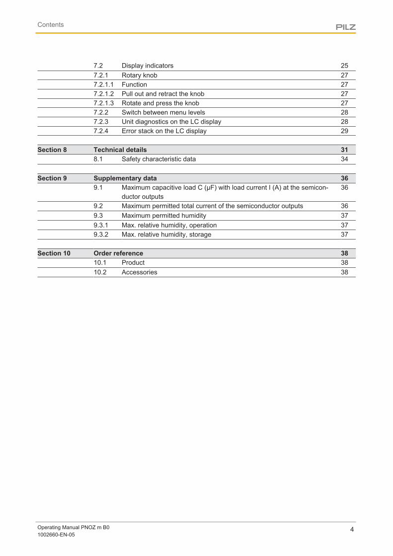
7.2 Display indicators 257.2.1 Rotary knob 277.2.1.1 Function 277.2.1.2 Pull out and retract the knob 277.2.1.3 Rotate and press the knob 277.2.2 Switch between menu levels 287.2.3 Unit diagnostics on the LC display 287.2.4 Error stack on the LC display 29
Section 8 Technical details 318.1 Safety characteristic data 34
Section 9 Supplementary data 369.1 Maximum capacitive load C (μF) with load current I (A) at the semicon-
ductor outputs36
9.2 Maximum permitted total current of the semiconductor outputs 369.3 Maximum permitted humidity 379.3.1 Max. relative humidity, operation 379.3.2 Max. relative humidity, storage 37
Section 10 Order reference 3810.1 Product 3810.2 Accessories 38
Introduction
Operating Manual PNOZ m B01002660-EN-05
5
1 Introduction
1.1 Validity of documentationThis documentation is valid for the product PNOZ m B0. It is valid until new documentationis published.
This operating manual explains the function and operation, describes the installation andprovides guidelines on how to connect the product.
1.2 Using the documentationThis document is intended for instruction. Only install and commission the product if youhave read and understood this document. The document should be retained for future ref-erence.
1.3 Definition of symbolsInformation that is particularly important is identified as follows:
DANGER!
This warning must be heeded! It warns of a hazardous situation that posesan immediate threat of serious injury and death and indicates preventivemeasures that can be taken.
WARNING!
This warning must be heeded! It warns of a hazardous situation that couldlead to serious injury and death and indicates preventive measures that canbe taken.
CAUTION!
This refers to a hazard that can lead to a less serious or minor injury plusmaterial damage, and also provides information on preventive measuresthat can be taken.
NOTICE
This describes a situation in which the product or devices could be dam-aged and also provides information on preventive measures that can betaken. It also highlights areas within the text that are of particular import-ance.
Introduction
Operating Manual PNOZ m B01002660-EN-05
6
INFORMATION
This gives advice on applications and provides information on special fea-tures.
Overview
Operating Manual PNOZ m B01002660-EN-05
7
2 Overview
2.1 Range} Base unit PNOZ m B0
} Terminator
} Documentation on data medium
2.2 Unit featuresUsing the product PNOZ m B0:
Base unit of the configurable control system PNOZmulti 2
The product has the following features:
} Can be configured in the PNOZmulti Configurator
} Semiconductor outputs:4 safety outputs Depending on the application, up to PL e of EN ISO 13849-1 and up to SIL CL 3 of ENIEC 62061
} 12 inputs for connecting, for example:
– Emergency stop pushbuttons
– Two-hand pushbuttons
– Safety gate limit switches
– Reset buttons
– Light beam devices
– Scanners
– Enabling switches
– PSEN
– Operating mode selector switches
} 8 configurable inputs/outputsCan be configured as:
– Inputs (see above for connection options)or
– Auxiliary outputs
} 4 configurable outputsCan be configured as:
– Auxiliary outputsor
– Test pulse outputs
} LED for:
– Error messages
– Diagnostics
Overview
Operating Manual PNOZ m B01002660-EN-05
8
– Supply voltage
– Fault at the outputs
– Fault at the inputs
} Backlit display for:
– Error messages
– State of supply voltage
– State of inputs/outputs
– Status information
– Device information
} Test pulse outputs used to monitor shorts across the inputs
} Monitoring of shorts between the safety outputs
} Plug-in connection terminals:Either spring-loaded terminal or screw terminal available as an accessory (see orderreference)
} Rotary knob for menu control
} Expansion modules can be connected(please refer to the document "PNOZmulti System Expansion" for details of the typeand number that can be connected)
2.3 Chip cardTo be able to use the product you will need a chip card.
Chip cards are available with memories of 8 kByte and 32 kByte. For large-scale projectswe recommend the 32 kByte chip card (see Technical Catalogue: Accessories chapter).
Overview
Operating Manual PNOZ m B01002660-EN-05
9
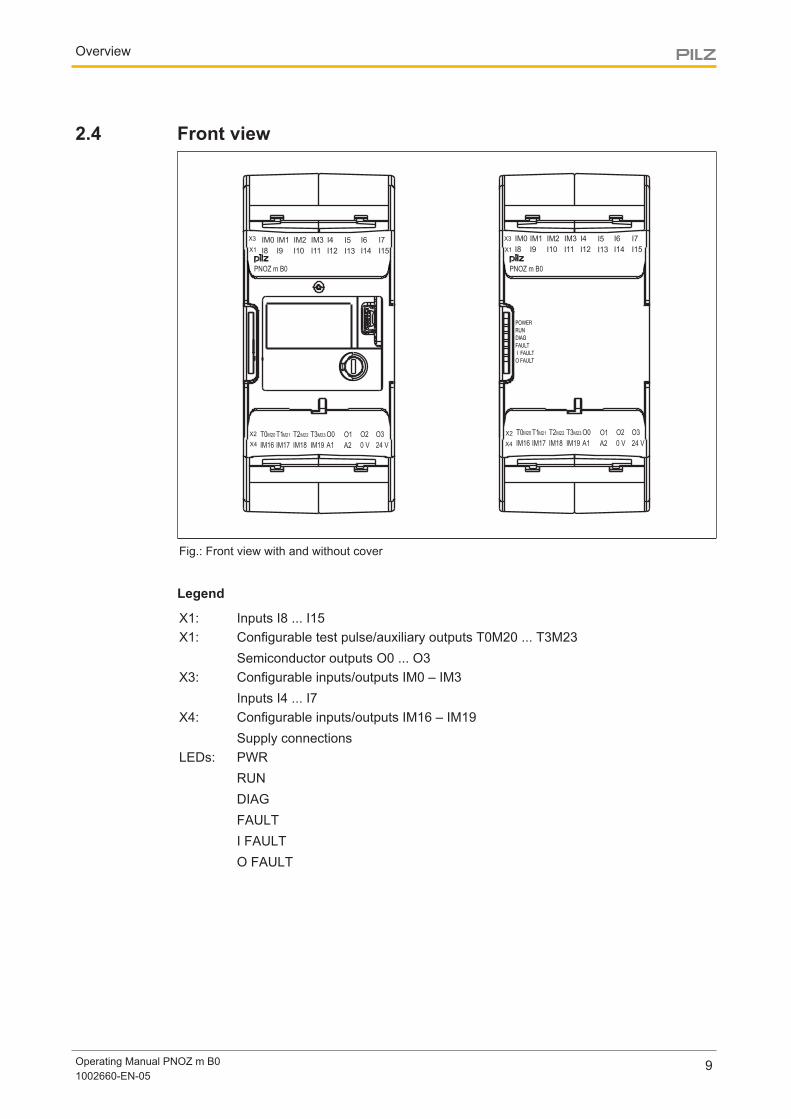
2.4 Front view
X3
X1
X4
X2
PNOZ m B0
IM0 IM1 IM2 I6I5I4IM3 I7
I8 I9 I10 I14I13I12I11 I15
X3
X1
X4
X2
PNOZ m B0
T0 T1 T2 O2O1O0T3 O3
IM16 IM17 IM18 0 VA2A1IM19 24 V
M20 M21 M22 M23
IM0 IM1 IM2 I6I5I4IM3 I7
I8 I9 I10 I14I13I12I11 I15
T0 T1 T2 O2O1O0T3 O3
IM16 IM17 IM18 0 VA2A1IM19 24 V
M20 M21 M22 M23
Fig.: Front view with and without cover
Legend
X1: Inputs I8 ... I15X1: Configurable test pulse/auxiliary outputs T0M20 ... T3M23
Semiconductor outputs O0 ... O3X3: Configurable inputs/outputs IM0 – IM3
Inputs I4 ... I7X4: Configurable inputs/outputs IM16 – IM19
Supply connectionsLEDs: PWR
RUNDIAGFAULTI FAULTO FAULT
Safety
Operating Manual PNOZ m B01002660-EN-05
10
3 Safety
3.1 Intended useThe configurable system PNOZmulti 2 is used for the safety-related interruption of safetycircuits and is designed for use in:
} Emergency stop equipment
} Safety circuits in accordance with VDE 0113 Part 1 and EN 60204-1
CAUTION!
Inputs and outputs for standard functions must not be used for safety-re-lated applications.
The following is deemed improper use in particular:
} Any component, technical or electrical modification to the product
} Use of the product outside the areas described in this manual
} Use of the product outside the technical details (see Technical details [ 31]).
NOTICEEMC-compliant electrical installation
The product is designed for use in an industrial environment. The productmay cause interference if installed in other environments. If installed in otherenvironments, measures should be taken to comply with the applicablestandards and directives for the respective installation site with regard to in-terference.
3.2 System requirementsPlease refer to the "Product Modifications" document in the "Version overview" section fordetails of which versions of the PNOZmulti Configurator can be used for this product.
3.3 Safety regulations
3.3.1 Safety assessmentBefore using a unit it is necessary to perform a safety assessment in accordance with theMachinery Directive.
Functional safety is guaranteed for the product as a single component. However, this doesnot guarantee the functional safety of the overall plant/machine. In order to achieve the re-quired safety level for the overall plant/machine, define the safety requirements for theplant/machine and then define how these must be implemented from a technical and organ-isational standpoint.
Safety
Operating Manual PNOZ m B01002660-EN-05
11
3.3.2 Use of qualified personnelThe products may only be assembled, installed, programmed, commissioned, operated,maintained and decommissioned by competent persons.
A competent person is someone who, because of their training, experience and current pro-fessional activity, has the specialist knowledge required to test, assess and operate thework equipment, devices, systems, plant and machinery in accordance with the generalstandards and guidelines for safety technology.
It is the company’s responsibility only to employ personnel who:
} Are familiar with the basic regulations concerning health and safety / accident preven-tion
} Have read and understood the information provided in this description under "Safety"
} And have a good knowledge of the generic and specialist standards applicable to thespecific application.
3.3.3 Warranty and liabilityAll claims to warranty and liability will be rendered invalid if
} The product was used contrary to the purpose for which it is intended
} Damage can be attributed to not having followed the guidelines in the manual
} Operating personnel are not suitably qualified
} Any type of modification has been made (e.g. exchanging components on the PCBboards, soldering work etc.).
3.3.4 Disposal} In safety-related applications, please comply with the mission time TM in the safety-re-
lated characteristic data.
} When decommissioning, please comply with local regulations regarding the disposal ofelectronic devices (e.g. Electrical and Electronic Equipment Act).
3.3.5 For your safetyThe device meets all the necessary conditions for safe operation. However, you should al-ways ensure that the following safety requirements are met:
} This operating manual only describes the basic functions of the device. Advanced func-tions are described in the online help for the PNOZmulti Configurator, in the"PNOZmulti Communication Interfaces" document and in "PNOZmulti Special Applica-tions". Only use these functions once you have read and understood the documenta-tion.
} You must note the information stated in the PNOZmulti Safety Manual.
} Adequate protection must be provided for all inductive consumers.
} Do not open the housing or make any unauthorised modifications.
} Please make sure you shut down the supply voltage when performing maintenancework (e.g. exchanging contactors).
Function description
Operating Manual PNOZ m B01002660-EN-05
12
4 Function description
4.1 Integrated protection mechanismsThe relay conforms to the following safety criteria:
} The circuit is redundant with built-in self-monitoring.
} The safety function remains effective in the case of a component failure.
} The safety outputs are tested periodically using a disconnection test.
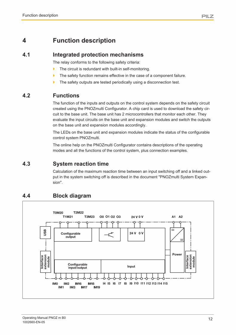
4.2 FunctionsThe function of the inputs and outputs on the control system depends on the safety circuitcreated using the PNOZmulti Configurator. A chip card is used to download the safety cir-cuit to the base unit. The base unit has 2 microcontrollers that monitor each other. Theyevaluate the input circuits on the base unit and expansion modules and switch the outputson the base unit and expansion modules accordingly.
The LEDs on the base unit and expansion modules indicate the status of the configurablecontrol system PNOZmulti.
The online help on the PNOZmulti Configurator contains descriptions of the operatingmodes and all the functions of the control system, plus connection examples.
4.3 System reaction timeCalculation of the maximum reaction time between an input switching off and a linked out-put in the system switching off is described in the document "PNOZmulti System Expan-sion".
4.4 Block diagram
=
Power
A1 A2
=
Input
Configurableoutput
24 V 0 V
24 V 0 VT1M21 O2O0 O1 O3
IM1
I8I5 I11I4 I9 I12 I13 I14 I15I7I6 I10IM2IM0IM3
IM16 IM18IM17 IM19
Inte
rfa
ce
exte
nsio
nm
od
ule
US
B
Inte
rfa
ce
exte
nsio
nm
od
ule
Configurableinput/output
T2M22
T3M23
T0M20
Function description
Operating Manual PNOZ m B01002660-EN-05
13
4.5 DiagnosticsThe status and error messages displayed by the LEDs are saved in an error stack. This er-ror stack can be shown on the display or can be read from the PNOZmulti Configurator viathe USB port.
Installation
Operating Manual PNOZ m B01002660-EN-05
14
5 Installation
5.1 Control cabinet installation} The unit should be installed in a control cabinet with a protection type of at least IP54.
} Install the system vertically on to a horizontal mounting rail. The venting slots must faceupward and downward. Other mounting positions could damage the safety system.
} Use the locking elements on the rear of the unit to attach it to a mounting rail.
} In environments exposed to heavy vibration, the unit should be secured using a fixingelement (e.g. retaining bracket or end angle).
} Open the locking slide before lifting the unit from the mounting rail.
} To comply with EMC requirements, the mounting rail must have a low impedance con-nection to the control cabinet housing.
NOTICE
Damage due to electrostatic discharge!
Electrostatic discharge can damage components. Ensure against dischargebefore touching the product, e.g. by touching an earthed, conductive sur-face or by wearing an earthed armband.
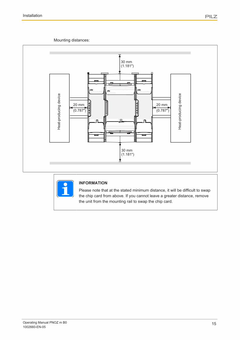
5.1.1 Mounting distancesWith control cabinet installation it is essential to maintain a certain distance from the topand bottom, as well as to other heat-producing devices (see diagram). The values statedfor the mounting distances are minimum specifications.
The ambient temperature in the control cabinet must not exceed the figure stated in thetechnical details. Air conditioning may otherwise be required.
Installation
Operating Manual PNOZ m B01002660-EN-05
15
Mounting distances:
30 mm(1.181")
30 mm(1.181")
20 mm
(0.787")
20 mm
(0.787")
IM0 IM1 IM2 I6I5I4IM3 I7
I8 I10 I14I13I12I11 I15
X3
X1
X4
X2
PNOZ mm0.1p
T0 T1 T2 O2O1O0T3 O3
IM16 IM17 IM18 0 VA2A1IM19 24 V
M20 M21 M22 M23
He
at-
pro
ducin
g d
evic
e
He
at-
pro
ducin
g d
evic
eINFORMATION
Please note that at the stated minimum distance, it will be difficult to swapthe chip card from above. If you cannot leave a greater distance, removethe unit from the mounting rail to swap the chip card.
Installation
Operating Manual PNOZ m B01002660-EN-05
16
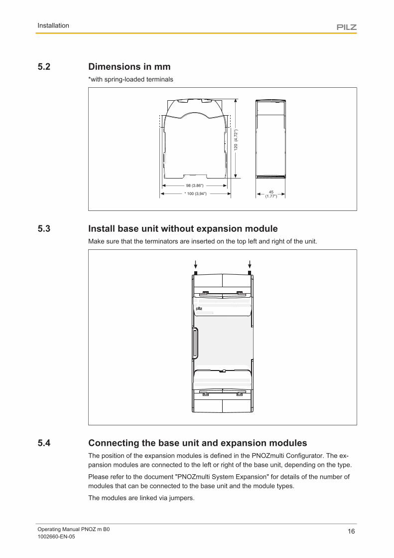
5.2 Dimensions in mm*with spring-loaded terminals
5.3 Install base unit without expansion moduleMake sure that the terminators are inserted on the top left and right of the unit.
IM0 IM1 IM2 I6I5I4IM3 I7
I8 I9 I10 I14I13I12I11 I15
X3
X1
X4
X2
PNOZ mm0.1p
T0 T1 T2 O2O1O0T3 O3
IM16 IM17 IM18 0 VA2A1IM19 24 V
M20 M21 M22 M23
5.4 Connecting the base unit and expansion modulesThe position of the expansion modules is defined in the PNOZmulti Configurator. The ex-pansion modules are connected to the left or right of the base unit, depending on the type.
Please refer to the document "PNOZmulti System Expansion" for details of the number ofmodules that can be connected to the base unit and the module types.
The modules are linked via jumpers.
Installation
Operating Manual PNOZ m B01002660-EN-05
17
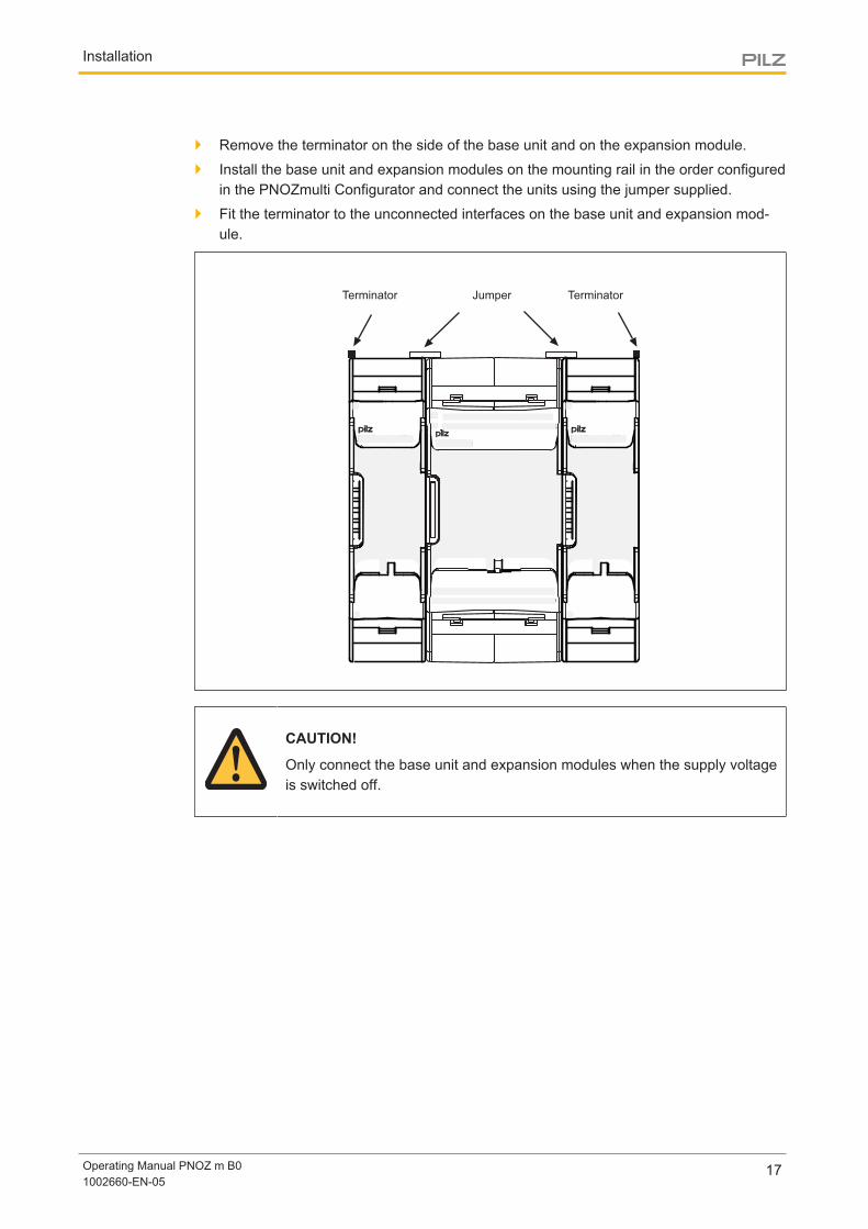
} Remove the terminator on the side of the base unit and on the expansion module.
} Install the base unit and expansion modules on the mounting rail in the order configuredin the PNOZmulti Configurator and connect the units using the jumper supplied.
} Fit the terminator to the unconnected interfaces on the base unit and expansion mod-ule.
Terminator Terminator
IM0 IM1 IM2 I6I5I4IM3 I7
I8 I10 I14I13I12I11 I15
X3
X1
X4
X2
PNOZ mm0.1p
T0 T1 T2 O2O1O0T3 O3
IM16 IM17 IM18 0 VA2A1IM19 24 V
M20 M21 M22 M23
Jumper
CAUTION!
Only connect the base unit and expansion modules when the supply voltageis switched off.
Commissioning
Operating Manual PNOZ m B01002660-EN-05
18
6 Commissioning
6.1 General wiring guidelinesThe wiring is defined in the circuit diagram in the Configurator. There you can select the in-puts that are to perform a safety function and the outputs that are to switch this safety func-tion.
Please note:
} Information given in the Technical details [ 31] must be followed.
} Outputs O0 to O3 are semiconductor outputs
} Use copper wiring with a temperature stability of 75 °C.
} Sufficient fuse protection must be provided on all output contacts with inductive loads.
} The safety system and input circuits must always be supplied by a single power supply.The power supply must meet the regulations for extra low voltages with protective sep-aration.
} Test pulse outputs must exclusively be used to test the inputs. They must not be usedto drive loads. Do not route the test pulse lines together with actuator cables within an unprotectedmulticore cable.
6.2 Commissioning the control systemProcedure:
} Wire the inputs and outputs on the base unit in accordance with the circuit diagram.
} Connect the supply voltage:
– Supply voltage for the control system:
– Terminal A1: + 24 VDC
– Terminal A2: 0 V
– Supply voltage for the semiconductor outputs:
– 24 V terminal: + 24 VDC
– 0V terminal: 0 V
Please note: The supply voltage for the semiconductor outputs must always be present,even if you are not using the semiconductor outputs.
When the voltages are fed separately using two power supplies, the supply voltage for thecontrol system and the supply voltage for the semiconductor outputs are galvanically isol-ated.
CAUTION!
Do not connect or disconnect expansion modules and terminators duringoperation.
Commissioning
Operating Manual PNOZ m B01002660-EN-05
19
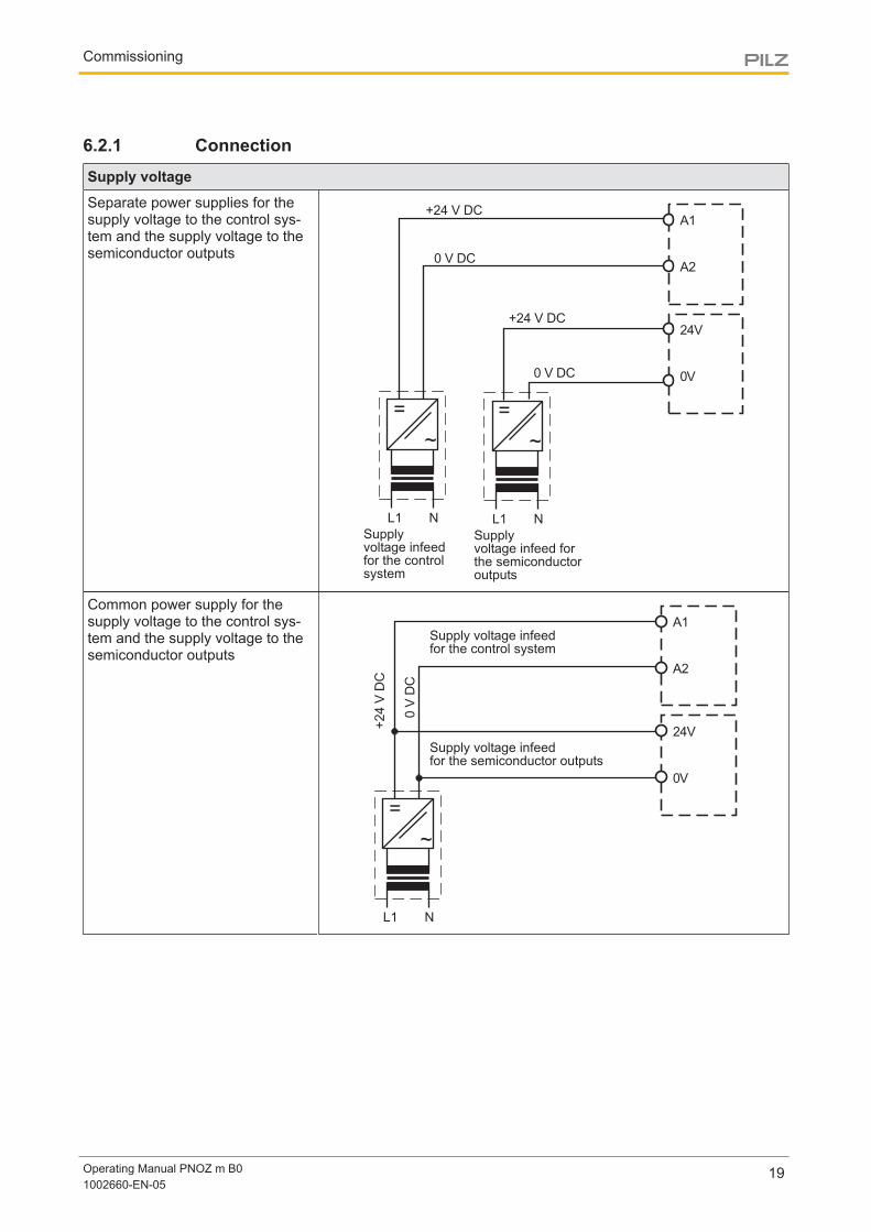
6.2.1 ConnectionSupply voltage
Separate power supplies for thesupply voltage to the control sys-tem and the supply voltage to thesemiconductor outputs
+24 V DC
0 V DC
Supplyvoltage infeedfor the controlsystem
Supplyvoltage infeed forthe semiconductoroutputs
0 V DC
+24 V DC
=
~
NL1
=
~
NL1
A1
A2
24V
0V
Common power supply for thesupply voltage to the control sys-tem and the supply voltage to thesemiconductor outputs
+24 V
DC
0 V
DC
=
~
NL1
A1
A2
24V
0V
Supply voltage infeedfor the control system
Supply voltage infeedfor the semiconductor outputs
Commissioning
Operating Manual PNOZ m B01002660-EN-05
20
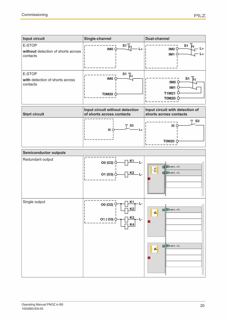
Input circuit Single-channel Dual-channel
E-STOPwithout detection of shorts acrosscontacts
S1
IM0 L+S1
IM1
IM0 L+
L+
E-STOPwith detection of shorts acrosscontacts
IM0
T0M20
S1
S1
T1M21
IM1
T0M20
IM0
Start circuitInput circuit without detectionof shorts across contacts
Input circuit with detection ofshorts across contacts
I5
S3
L+
I5
T0M20
S3
Semiconductor outputs
Redundant output
K2L-
O0 (O2)
O1 (O3)
K1L-
Single output
K3L-
K4
O0 (O2)
O1 ( O3)
K1L-
K2
Commissioning
Operating Manual PNOZ m B01002660-EN-05
21
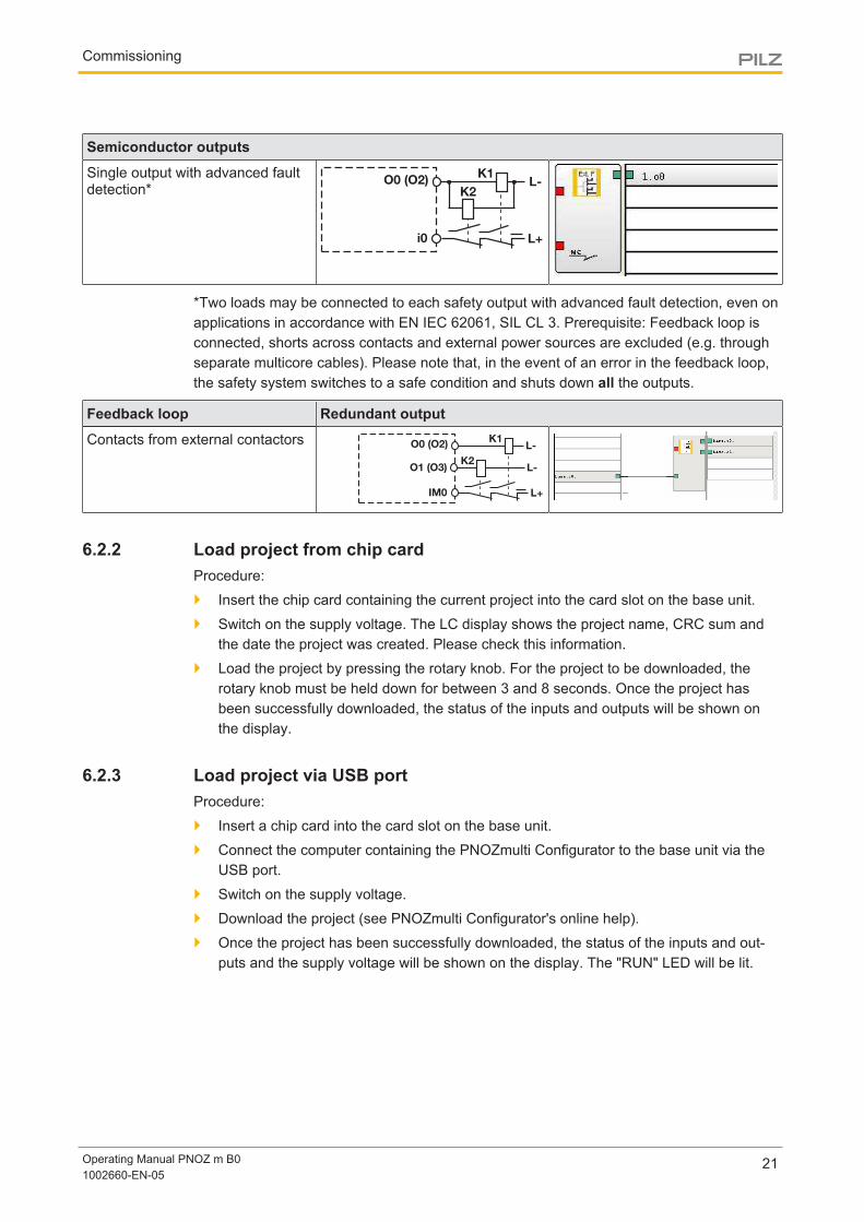
Semiconductor outputs
Single output with advanced faultdetection*
K1
L+
L-K2
O0 (O2)
i0
*Two loads may be connected to each safety output with advanced fault detection, even onapplications in accordance with EN IEC 62061, SIL CL 3. Prerequisite: Feedback loop isconnected, shorts across contacts and external power sources are excluded (e.g. throughseparate multicore cables). Please note that, in the event of an error in the feedback loop,the safety system switches to a safe condition and shuts down all the outputs.
Feedback loop Redundant output
Contacts from external contactors K1
L+
L-
K2
O0 (O2)
O1 (O3)
IM0
L-
6.2.2 Load project from chip cardProcedure:
} Insert the chip card containing the current project into the card slot on the base unit.
} Switch on the supply voltage. The LC display shows the project name, CRC sum andthe date the project was created. Please check this information.
} Load the project by pressing the rotary knob. For the project to be downloaded, therotary knob must be held down for between 3 and 8 seconds. Once the project hasbeen successfully downloaded, the status of the inputs and outputs will be shown onthe display.
6.2.3 Load project via USB portProcedure:
} Insert a chip card into the card slot on the base unit.
} Connect the computer containing the PNOZmulti Configurator to the base unit via theUSB port.
} Switch on the supply voltage.
} Download the project (see PNOZmulti Configurator's online help).
} Once the project has been successfully downloaded, the status of the inputs and out-puts and the supply voltage will be shown on the display. The "RUN" LED will be lit.
Commissioning
Operating Manual PNOZ m B01002660-EN-05
22
6.3 Function test during commissioning
CAUTION!
It is essential to check that the safety devices operate correctly
– after the chip card has been exchanged
– after a project has been downloaded
– when the project has been deleted from the base unit's memory ("Re-set Project" menu)
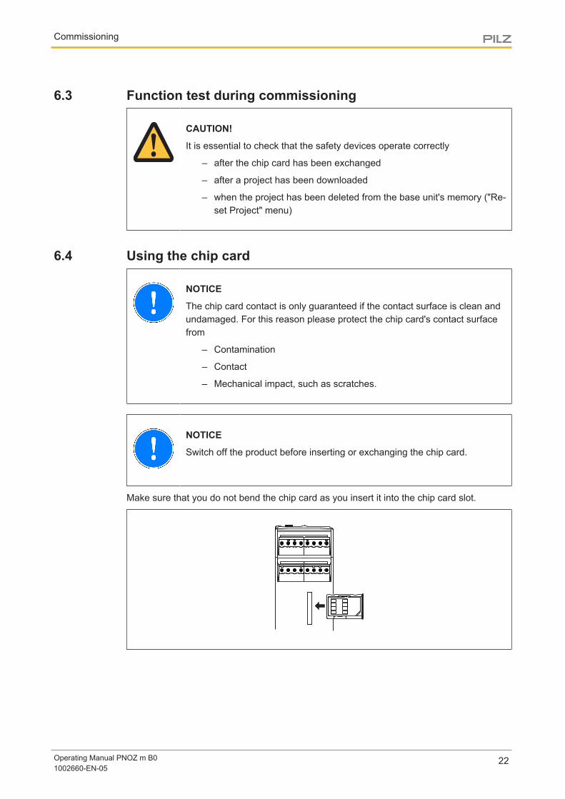
6.4 Using the chip card
NOTICE
The chip card contact is only guaranteed if the contact surface is clean andundamaged. For this reason please protect the chip card's contact surfacefrom
– Contamination
– Contact
– Mechanical impact, such as scratches.
NOTICE
Switch off the product before inserting or exchanging the chip card.
Make sure that you do not bend the chip card as you insert it into the chip card slot.
Commissioning
Operating Manual PNOZ m B01002660-EN-05
23
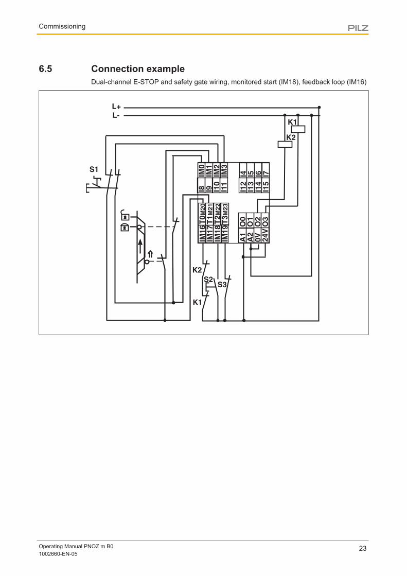
6.5 Connection exampleDual-channel E-STOP and safety gate wiring, monitored start (IM18), feedback loop (IM16)
IM0
IM1
IM2
IM3
I4 I5 I6 I7
I8 I9 I10
I11
I12
I13
I14
I15
IM16
IM17
IM18
IM19
T0M
20
T1M
21
T2M
22
T3M
23
O0
O1
O2
O3
A1
A2
24V
0V
K1
K2
S1
K2
K1
S2S3
L+
L-
Operation
Operating Manual PNOZ m B01002660-EN-05
24
7 OperationWhen the supply voltage is switched on, the PNOZmulti safety system copies the configur-ation from the chip card.
The LEDs “POWER”, “DIAG”, “FAULT”, “IFAULT” and “OFAULT” will light up on the baseunit.
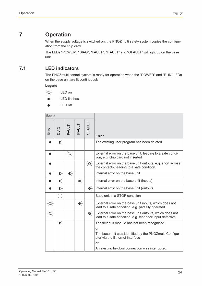
7.1 LED indicatorsThe PNOZmulti control system is ready for operation when the "POWER" and "RUN" LEDson the base unit are lit continuously.
Legend
LED on
LED flashes
LED off
Basis
ErrorRUN
DIAG
FAULT
IFAULT
OFAULT
The existing user program has been deleted.
External error on the base unit, leading to a safe condi-tion, e.g. chip card not inserted
External error on the base unit outputs, e.g. short acrossthe contacts, leading to a safe condition.
Internal error on the base unit
Internal error on the base unit (inputs)
Internal error on the base unit (outputs)
Base unit in a STOP condition
External error on the base unit inputs, which does notlead to a safe condition, e.g. partially operated
External error on the base unit outputs, which does notlead to a safe condition, e.g. feedback input defective
The fieldbus module has not been recognised.orThe base unit was identified by the PNOZmulti Configur-ator via the Ethernet interfaceorAn existing fieldbus connection was interrupted.
Operation
Operating Manual PNOZ m B01002660-EN-05
25
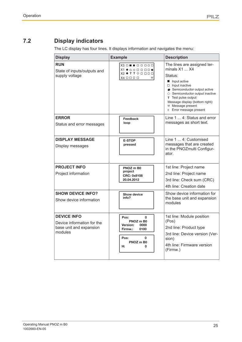
7.2 Display indicatorsThe LC display has four lines. It displays information and navigates the menu:
Display Example Description
RUNState of inputs/outputs andsupply voltage
X3
X1
X2
X4
T T
M
The lines are assigned ter-minals X1 ... X4Status:
Semiconductor output active
Semiconductor output inactive
Test pulse output
Message display (bottom right):Message present
Error message present
Input active
Input inactive
ERRORStatus and error messages
Feedback
loop
Line 1 ... 4: Status and errormessages as short text.
DISPLAY MESSAGEDisplay messages
E-STOP
pressed
Line 1 ... 4: Customisedmessages that are createdin the PNOZmulti Configur-ator.
PROJECT INFOProject information
PNOZ m B0project
CRC: 0x8108
20.04.2012
1st line: Project name2nd line: Project name3rd line: Check sum (CRC)4th line: Creation date
SHOW DEVICE INFO?Show device information
Show device
info?
Show device information forthe base unit and expansionmodules
DEVICE INFODevice information for thebase unit and expansionmodules
Pos: 0
Version: 0000
PNOZ m B0
Firmw.: 0100
Pos: 0
H: 0
PNOZ m B0
1st line: Module position(Pos)2nd line: Product type3rd line: Device version (Ver-sion)4th line: Firmware version(Firmw.)
Operation
Operating Manual PNOZ m B01002660-EN-05
26
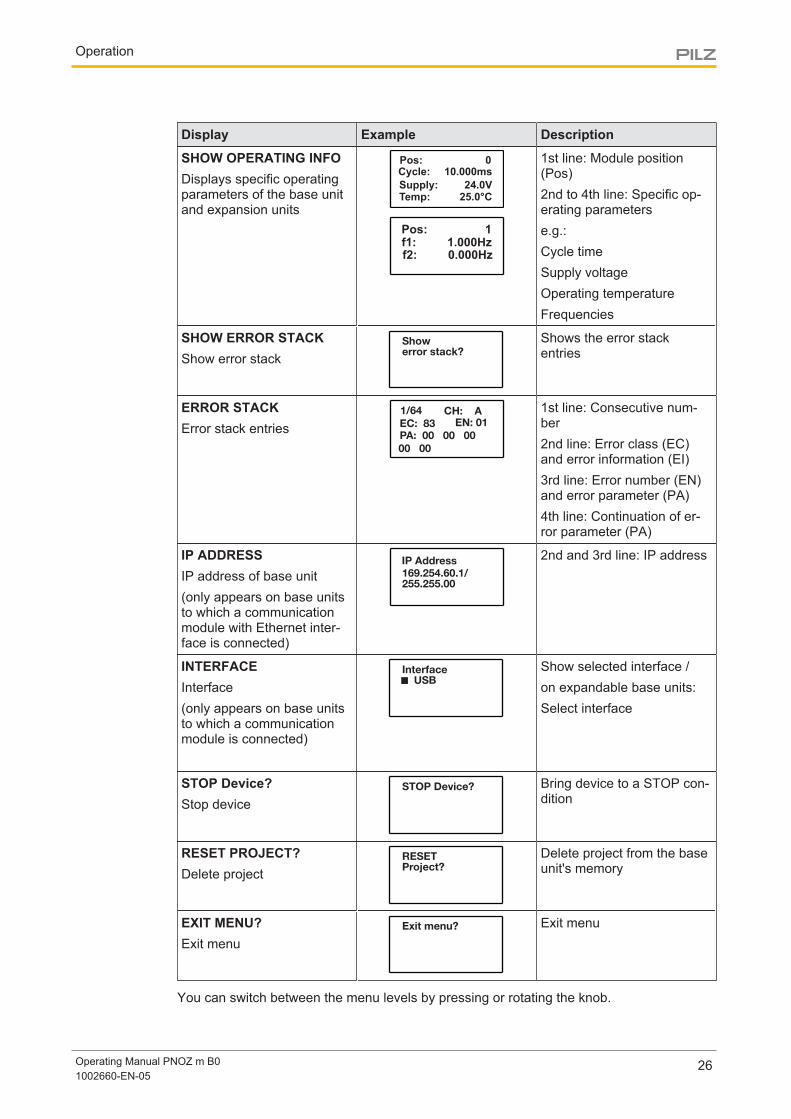
Display Example Description
SHOW OPERATING INFODisplays specific operatingparameters of the base unitand expansion units
Pos: 010.000ms
24.0V25.0°C
Cycle:
Supply:Temp:
Pos: 1
f1: 1.000Hz
f2: 0.000Hz
1st line: Module position(Pos)2nd to 4th line: Specific op-erating parameterse.g.:Cycle timeSupply voltageOperating temperatureFrequencies
SHOW ERROR STACKShow error stack
Show
error stack?
Shows the error stackentries
ERROR STACKError stack entries
1/64
PA: 00 00 00
EC: 83
00 00
EN: 01
CH: A 1st line: Consecutive num-ber2nd line: Error class (EC)and error information (EI)3rd line: Error number (EN)and error parameter (PA)4th line: Continuation of er-ror parameter (PA)
IP ADDRESSIP address of base unit(only appears on base unitsto which a communicationmodule with Ethernet inter-face is connected)
IP Address
169.254.60.1/
255.255.00
2nd and 3rd line: IP address
INTERFACEInterface(only appears on base unitsto which a communicationmodule is connected)
Interface
USB
Show selected interface /on expandable base units:Select interface
STOP Device?Stop device
STOP Device? Bring device to a STOP con-dition
RESET PROJECT?Delete project
RESETProject?
Delete project from the baseunit's memory
EXIT MENU?Exit menu
Exit menu? Exit menu
You can switch between the menu levels by pressing or rotating the knob.
Operation
Operating Manual PNOZ m B01002660-EN-05
27
7.2.1 Rotary knob
7.2.1.1 FunctionThe menu settings are made on the unit's display via a rotary knob. You have the option tomake the settings on the knob by hand or with a screwdriver. If you make the settings witha screwdriver, the knob can remain within the unit.
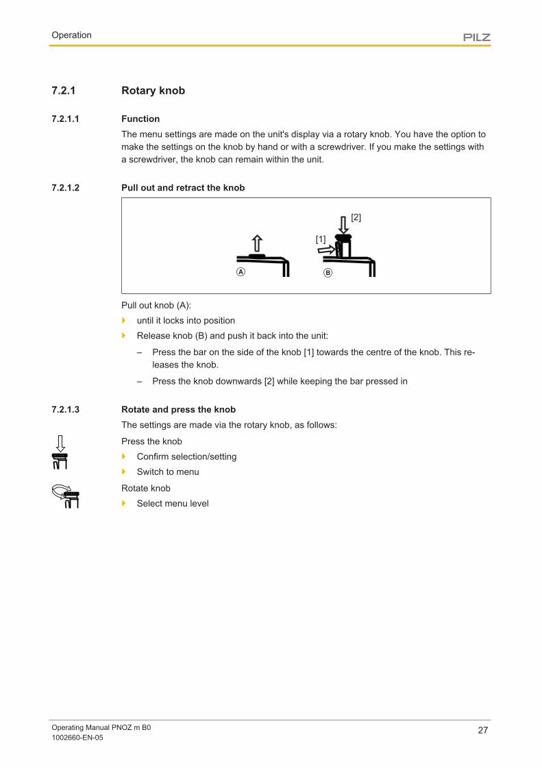
7.2.1.2 Pull out and retract the knob
[1]
[2]
Pull out knob (A):
} until it locks into position
} Release knob (B) and push it back into the unit:
– Press the bar on the side of the knob [1] towards the centre of the knob. This re-leases the knob.
– Press the knob downwards [2] while keeping the bar pressed in
7.2.1.3 Rotate and press the knobThe settings are made via the rotary knob, as follows:
Press the knob
} Confirm selection/setting
} Switch to menu
Rotate knob
} Select menu level
Operation
Operating Manual PNOZ m B01002660-EN-05
28
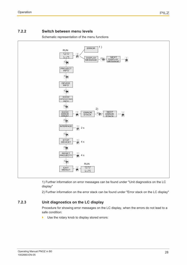
7.2.2 Switch between menu levelsSchematic representation of the menu functions
2)
1) Further information on error messages can be found under "Unit diagnostics on the LCdisplay"
2) Further information on the error stack can be found under "Error stack on the LC display"
7.2.3 Unit diagnostics on the LC displayProcedure for showing error messages on the LC display, when the errors do not lead to asafe condition:
} Use the rotary knob to display stored errors:
Operation
Operating Manual PNOZ m B01002660-EN-05
29
Outputfaulty
*X3
X1
X2
X4
T T
M
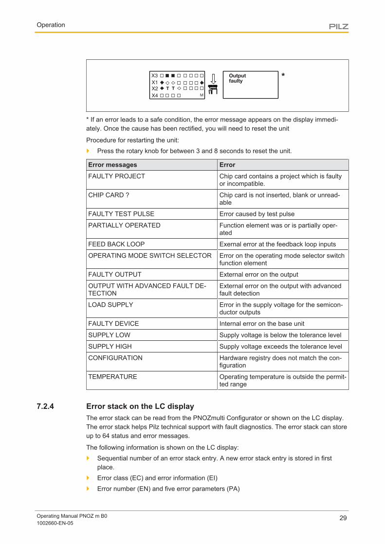
* If an error leads to a safe condition, the error message appears on the display immedi-ately. Once the cause has been rectified, you will need to reset the unit
Procedure for restarting the unit:
} Press the rotary knob for between 3 and 8 seconds to reset the unit.
Error messages Error
FAULTY PROJECT Chip card contains a project which is faultyor incompatible.
CHIP CARD ? Chip card is not inserted, blank or unread-able
FAULTY TEST PULSE Error caused by test pulse
PARTIALLY OPERATED Function element was or is partially oper-ated
FEED BACK LOOP Exernal error at the feedback loop inputs
OPERATING MODE SWITCH SELECTOR Error on the operating mode selector switchfunction element
FAULTY OUTPUT External error on the output
OUTPUT WITH ADVANCED FAULT DE-TECTION
External error on the output with advancedfault detection
LOAD SUPPLY Error in the supply voltage for the semicon-ductor outputs
FAULTY DEVICE Internal error on the base unit
SUPPLY LOW Supply voltage is below the tolerance level
SUPPLY HIGH Supply voltage exceeds the tolerance level
CONFIGURATION Hardware registry does not match the con-figuration
TEMPERATURE Operating temperature is outside the permit-ted range
7.2.4 Error stack on the LC displayThe error stack can be read from the PNOZmulti Configurator or shown on the LC display.The error stack helps Pilz technical support with fault diagnostics. The error stack can storeup to 64 status and error messages.
The following information is shown on the LC display:
} Sequential number of an error stack entry. A new error stack entry is stored in firstplace.
} Error class (EC) and error information (EI)
} Error number (EN) and five error parameters (PA)
Operation
Operating Manual PNOZ m B01002660-EN-05
30
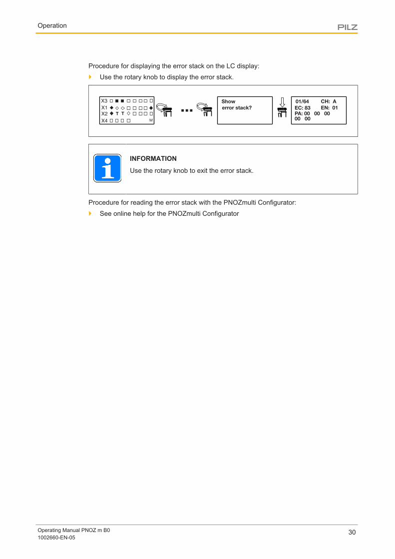
Procedure for displaying the error stack on the LC display:
} Use the rotary knob to display the error stack.
01/64
PA: 00 00 00
00 00
EC: 83 EN: 01
Show
error stack?
X3
X1
X2
X4
T T
M
...CH: A
INFORMATION
Use the rotary knob to exit the error stack.
Procedure for reading the error stack with the PNOZmulti Configurator:
} See online help for the PNOZmulti Configurator
Technical details
Operating Manual PNOZ m B01002660-EN-05
31
8 Technical details
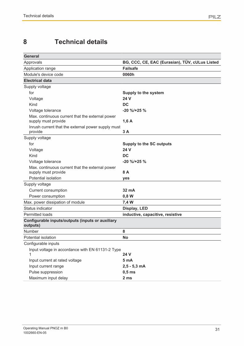
GeneralApprovals BG, CCC, CE, EAC (Eurasian), TÜV, cULus ListedApplication range FailsafeModule's device code 0060hElectrical dataSupply voltage
for Supply to the systemVoltage 24 VKind DCVoltage tolerance -20 %/+25 %Max. continuous current that the external powersupply must provide 1,6 AInrush current that the external power supply mustprovide 3 A
Supply voltagefor Supply to the SC outputsVoltage 24 VKind DCVoltage tolerance -20 %/+25 %Max. continuous current that the external powersupply must provide 8 APotential isolation yes
Supply voltageCurrent consumption 32 mAPower consumption 0,8 W
Max. power dissipation of module 7,4 WStatus indicator Display, LEDPermitted loads inductive, capacitive, resistiveConfigurable inputs/outputs (inputs or auxiliaryoutputs)Number 8Potential isolation NoConfigurable inputs
Input voltage in accordance with EN 61131-2 Type1 24 VInput current at rated voltage 5 mAInput current range 2,5 - 5,3 mAPulse suppression 0,5 msMaximum input delay 2 ms
Technical details
Operating Manual PNOZ m B01002660-EN-05
32
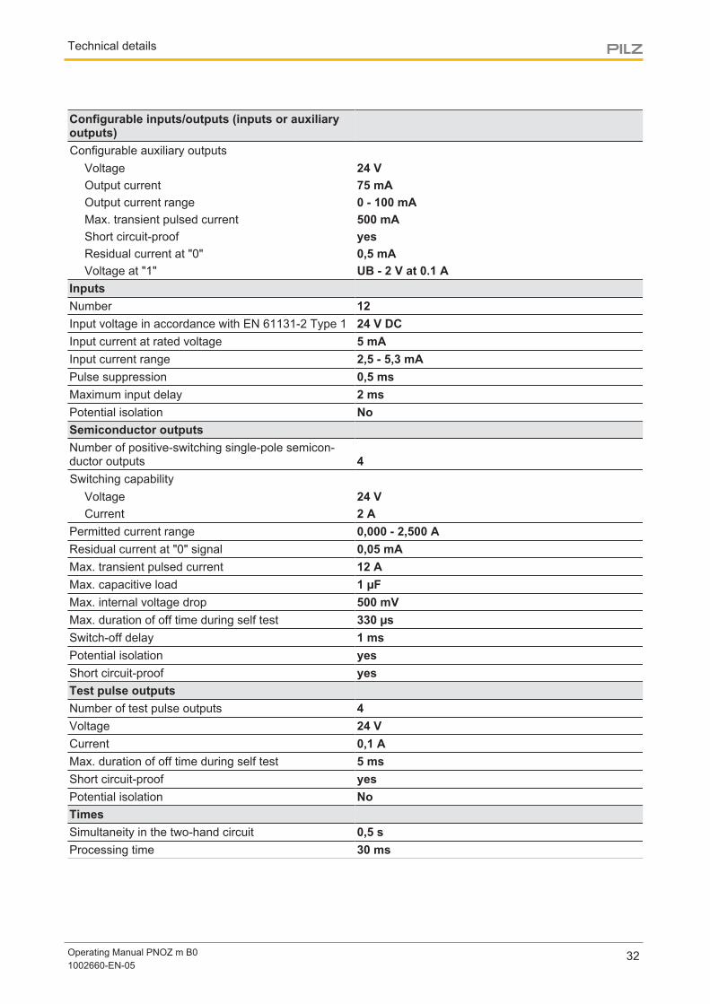
Configurable inputs/outputs (inputs or auxiliaryoutputs)Configurable auxiliary outputs
Voltage 24 VOutput current 75 mAOutput current range 0 - 100 mAMax. transient pulsed current 500 mAShort circuit-proof yesResidual current at "0" 0,5 mAVoltage at "1" UB - 2 V at 0.1 A
InputsNumber 12Input voltage in accordance with EN 61131-2 Type 1 24 V DCInput current at rated voltage 5 mAInput current range 2,5 - 5,3 mAPulse suppression 0,5 msMaximum input delay 2 msPotential isolation NoSemiconductor outputsNumber of positive-switching single-pole semicon-ductor outputs 4Switching capability
Voltage 24 VCurrent 2 A
Permitted current range 0,000 - 2,500 AResidual current at "0" signal 0,05 mAMax. transient pulsed current 12 AMax. capacitive load 1 µFMax. internal voltage drop 500 mVMax. duration of off time during self test 330 µsSwitch-off delay 1 msPotential isolation yesShort circuit-proof yesTest pulse outputsNumber of test pulse outputs 4Voltage 24 VCurrent 0,1 AMax. duration of off time during self test 5 msShort circuit-proof yesPotential isolation NoTimesSimultaneity in the two-hand circuit 0,5 sProcessing time 30 ms
Technical details
Operating Manual PNOZ m B01002660-EN-05
33
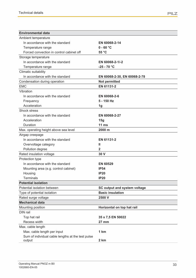
Environmental dataAmbient temperature
In accordance with the standard EN 60068-2-14Temperature range 0 - 60 °CForced convection in control cabinet off 55 °C
Storage temperatureIn accordance with the standard EN 60068-2-1/-2Temperature range -25 - 70 °C
Climatic suitabilityIn accordance with the standard EN 60068-2-30, EN 60068-2-78
Condensation during operation Not permittedEMC EN 61131-2Vibration
In accordance with the standard EN 60068-2-6Frequency 5 - 150 HzAcceleration 1g
Shock stressIn accordance with the standard EN 60068-2-27Acceleration 15gDuration 11 ms
Max. operating height above sea level 2000 mAirgap creepage
In accordance with the standard EN 61131-2Overvoltage category IIPollution degree 2
Rated insulation voltage 30 VProtection type
In accordance with the standard EN 60529Mounting area (e.g. control cabinet) IP54Housing IP20Terminals IP20
Potential isolationPotential isolation between SC output and system voltageType of potential isolation Basic insulationRated surge voltage 2500 VMechanical dataMounting position Horizontal on top hat railDIN rail
Top hat rail 35 x 7,5 EN 50022Recess width 27 mm
Max. cable lengthMax. cable length per input 1 kmSum of individual cable lengths at the test pulseoutput 2 km
Technical details
Operating Manual PNOZ m B01002660-EN-05
34
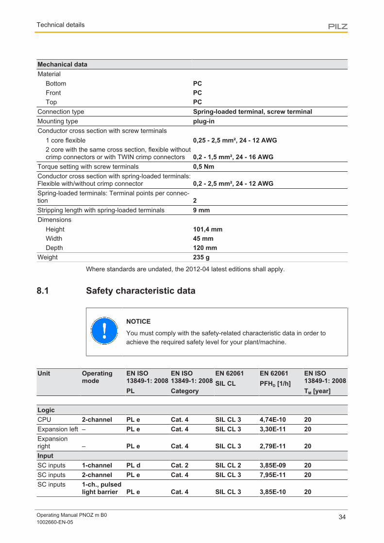
Mechanical dataMaterial
Bottom PCFront PCTop PC
Connection type Spring-loaded terminal, screw terminalMounting type plug-inConductor cross section with screw terminals
1 core flexible 0,25 - 2,5 mm², 24 - 12 AWG2 core with the same cross section, flexible withoutcrimp connectors or with TWIN crimp connectors 0,2 - 1,5 mm², 24 - 16 AWG
Torque setting with screw terminals 0,5 NmConductor cross section with spring-loaded terminals:Flexible with/without crimp connector 0,2 - 2,5 mm², 24 - 12 AWGSpring-loaded terminals: Terminal points per connec-tion 2Stripping length with spring-loaded terminals 9 mmDimensions
Height 101,4 mmWidth 45 mmDepth 120 mm
Weight 235 g
Where standards are undated, the 2012-04 latest editions shall apply.
8.1 Safety characteristic data
NOTICE
You must comply with the safety-related characteristic data in order toachieve the required safety level for your plant/machine.
Unit Operatingmode
EN ISO13849-1: 2008PL
EN ISO13849-1: 2008Category
EN 62061SIL CL
EN 62061PFHD [1/h]
EN ISO13849-1: 2008TM [year]
LogicCPU 2-channel PL e Cat. 4 SIL CL 3 4,74E-10 20Expansion left – PL e Cat. 4 SIL CL 3 3,30E-11 20Expansionright – PL e Cat. 4 SIL CL 3 2,79E-11 20InputSC inputs 1-channel PL d Cat. 2 SIL CL 2 3,85E-09 20SC inputs 2-channel PL e Cat. 4 SIL CL 3 7,95E-11 20SC inputs 1-ch., pulsed
light barrier PL e Cat. 4 SIL CL 3 3,85E-10 20
Technical details
Operating Manual PNOZ m B01002660-EN-05
35
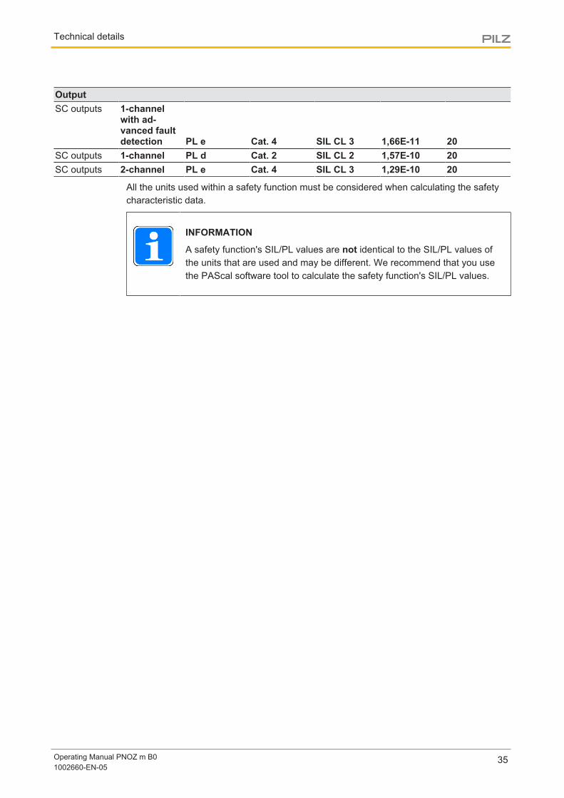
OutputSC outputs 1-channel
with ad-vanced faultdetection PL e Cat. 4 SIL CL 3 1,66E-11 20
SC outputs 1-channel PL d Cat. 2 SIL CL 2 1,57E-10 20SC outputs 2-channel PL e Cat. 4 SIL CL 3 1,29E-10 20
All the units used within a safety function must be considered when calculating the safetycharacteristic data.
INFORMATION
A safety function's SIL/PL values are not identical to the SIL/PL values ofthe units that are used and may be different. We recommend that you usethe PAScal software tool to calculate the safety function's SIL/PL values.
Supplementary data
Operating Manual PNOZ m B01002660-EN-05
36
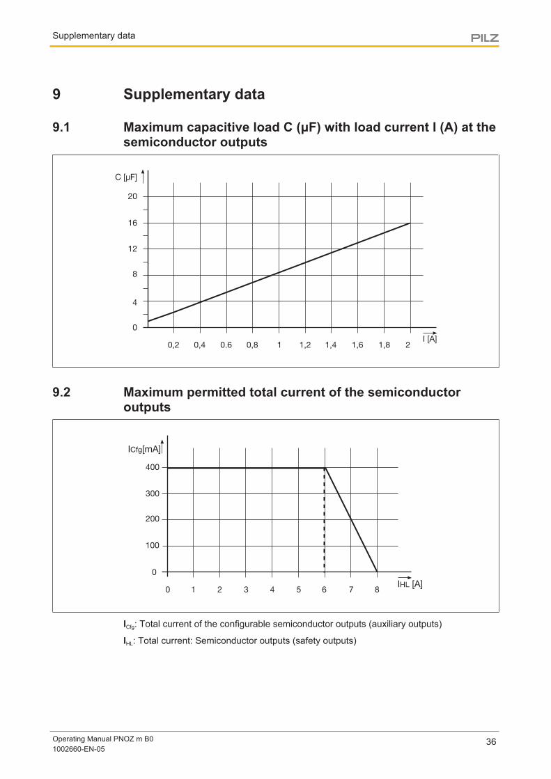
9 Supplementary data
9.1 Maximum capacitive load C (μF) with load current I (A) at thesemiconductor outputs
4
8
12
16
20
0
0,2 0,4 0.6 0,8 1 1,2 1,4 1,6 1,8 2I [A]
C [µF]
9.2 Maximum permitted total current of the semiconductoroutputs
100
200
300
400
0
1 2 3 4 5 6 7 8IHL [A]
ICfg[mA]
0
ICfg: Total current of the configurable semiconductor outputs (auxiliary outputs)
IHL: Total current: Semiconductor outputs (safety outputs)
Supplementary data
Operating Manual PNOZ m B01002660-EN-05
37
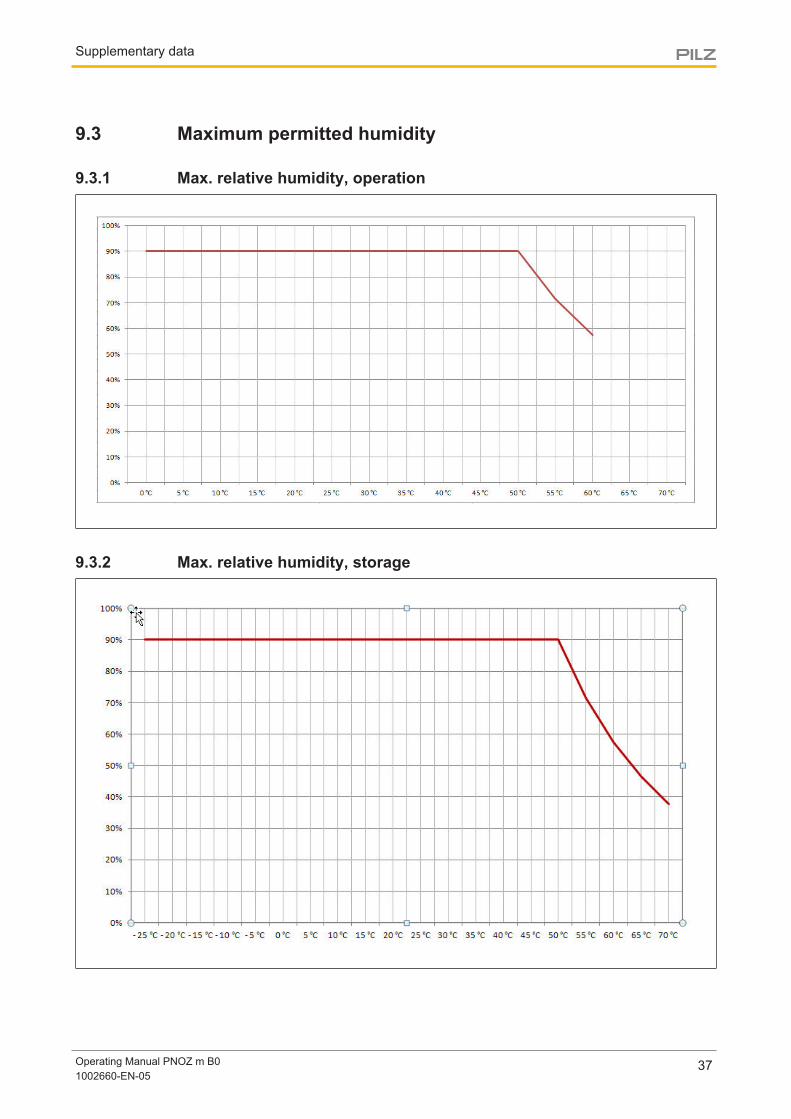
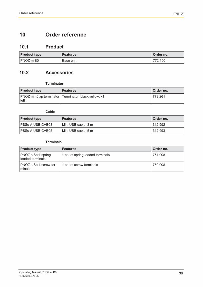
9.3 Maximum permitted humidity
9.3.1 Max. relative humidity, operation
9.3.2 Max. relative humidity, storage
Order reference
Operating Manual PNOZ m B01002660-EN-05
38
10 Order reference
10.1 ProductProduct type Features Order no.
PNOZ m B0 Base unit 772 100
10.2 Accessories
Terminator
Product type Features Order no.
PNOZ mm0.xp terminatorleft
Terminator, black/yellow, x1 779 261
Cable
Product type Features Order no.
PSSu A USB-CAB03 Mini USB cable, 3 m 312 992
PSSu A USB-CAB05 Mini USB cable, 5 m 312 993
Terminals
Product type Features Order no.
PNOZ s Set1 springloaded terminals
1 set of spring-loaded terminals 751 008
PNOZ s Set1 screw ter-minals
1 set of screw terminals 750 008
The Best of German Engineering
Partner of:
SupportTechnical support is available from Pilz round the clock.
Americas
Brazil
+55 11 97569-2804
Canada
+1 888-315-PILZ (315-7459)
Mexico
+52 55 5572 1300
USA (toll-free)
+1 877-PILZUSA (745-9872)
Asia
China
+86 21 60880878-216
Japan
+81 45 471-2281
South Korea
+82 31 450 0680
Australia
+61 3 95446300
Europe
Austria
+43 1 7986263-0
Belgium, Luxembourg
+32 9 3217575
France
+33 3 88104000
Germany
+49 711 3409-444
Ireland
+353 21 4804983
Italy
+39 0362 1826711
Scandinavia
+45 74436332
Spain
+34 938497433
Switzerland
+41 62 88979-30
The Netherlands
+31 347 320477
Turkey
+90 216 5775552
United Kingdom
+44 1536 462203
You can reach our
international hotline on:
+49 711 3409-444
CM
SE®
, Ind
uraN
ET p
®, P
AS
4000
®, P
AS
cal®
, PA
Sco
nfig®
, Pilz
®, P
IT®, P
LID
®, P
MC
prim
o®, P
MC
prot
ego®
, PM
Cte
ndo®
, PM
D®, P
MI®
, PN
OZ®
, Prim
o®, P
SEN
®, P
SS
®, P
VIS
®, S
afet
yBU
S p
®,
Saf
etyE
YE®
, Saf
etyN
ET p
®, T
hE
SP
IrIT
Of
SA
fETY
® a
re re
gist
ered
and
pro
tect
ed tr
adem
arks
of P
ilz G
mbh
& C
o. K
G in
som
e co
untr
ies.
We
wou
ld p
oint
out
that
pro
duct
feat
ures
may
var
y
from
the
deta
ils s
tate
d in
this
doc
umen
t, de
pend
ing
on th
e st
atus
at t
he ti
me
of p
ublic
atio
n an
d th
e sc
ope
of th
e eq
uipm
ent.
We
acce
pt n
o re
spon
sibi
lity
for
the
valid
ity, a
ccur
acy
an
d en
tiret
y of
the
text
and
gra
phic
s pr
esen
ted
in th
is in
form
atio
n. P
leas
e co
ntac
t our
Tec
hnic
al S
uppo
rt if
you
hav
e an
y qu
estio
ns.
Pilz develops environmentally-friendly products using
ecological materials and energy-saving technologies.
Offices and production facilities are ecologically designed,
environmentally-aware and energy-saving. So Pilz offers
sustainability, plus the security of using energy-efficient
products and environmentally-friendly solutions.
Pilz Gmbh & Co. KG
felix-Wankel-Straße 2
73760 Ostfildern, Germany
Tel.: +49 711 3409-0
fax: +49 711 3409-133
www.pilz.com
100X
XXX-
DE-
0X0-
0-1-
3-00
0, 2
015-
00 P
rinte
d in
Ger
man
y©
Pilz
Gm
bh &
Co.
KG
, 201
5
1002
660-
EN
-05,
201
5-09
Prin
ted
in G
erm
any
© P
ilz G
mbH
& C
o. K
G, 2
015
Back cover