Embed Size (px)
Citation preview
Pneumatics and HydraulicsLecture 13: Pneumatic system design and
development part 3Dr. Ahmad Al-Mahasneh
In the previous lecture
• Control system development
• Positional sketch
• Motion diagram
• Control chart
• Function diagram
Outline
• Abbreviated notation
• Function chart
• Circuit diagram
• The lifecycle of pneumatic systems
• Development of Pneumatic circuits
• Sizing of pneumatic valves
Control System Development (last lecture)
•The development of the control system solution requires that the problem is definedclearly.
•There are many ways of representing the problem in a descriptive or graphical form.
The methods of representing the control problem include:• Positional sketch
• Motion diagram:
-Displacement-Step Diagram.
-Displacement-Time Diagram.
• Control chart
• Function diagram
• Function chart
• Circuit diagram
Positional sketch (last lecture)
•The positional sketch shows the relationship between the actuators
and the machine fixture.
•The actuators are shown in the correct orientation.
•The positional sketch is not normally to scale and should not be
too detailed.
•The diagram will be used in conjunction with the description of
the machine operation and the motion diagrams.
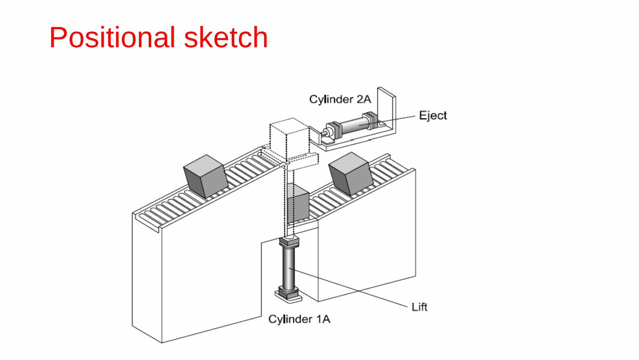
Positional sketch
Motion diagram
•The displacement-step diagram and the displacement-time
diagram are used for motion sequences.
•The displacement-step diagram represents the operating
sequence of the actuators; the displacement is recorded in
relation to the sequence step.
• If a control system incorporates a number of actuators, they are
shown in the same way and are drawn one below the other.
•Their interrelation can be seen by comparing the steps.
Motion diagram: Displacement-step diagram
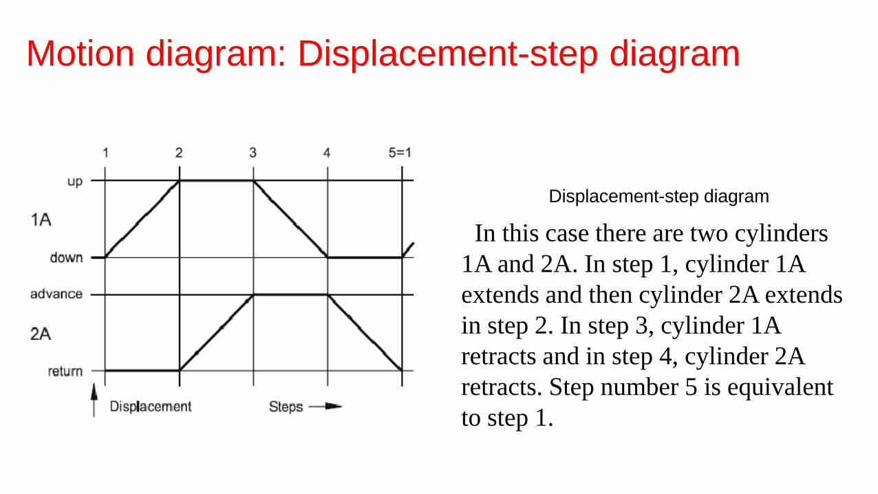
Displacement-step diagram
In this case there are two cylinders
1A and 2A. In step 1, cylinder 1A
extends and then cylinder 2A extends
in step 2. In step 3, cylinder 1A
retracts and in step 4, cylinder 2A
retracts. Step number 5 is equivalent
to step 1.
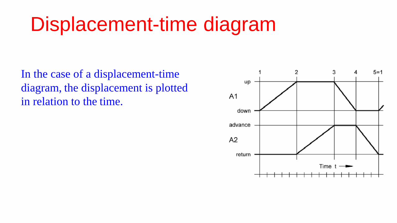
Displacement-time diagram
In the case of a displacement-time
diagram, the displacement is plotted
in relation to the time.
Control chart
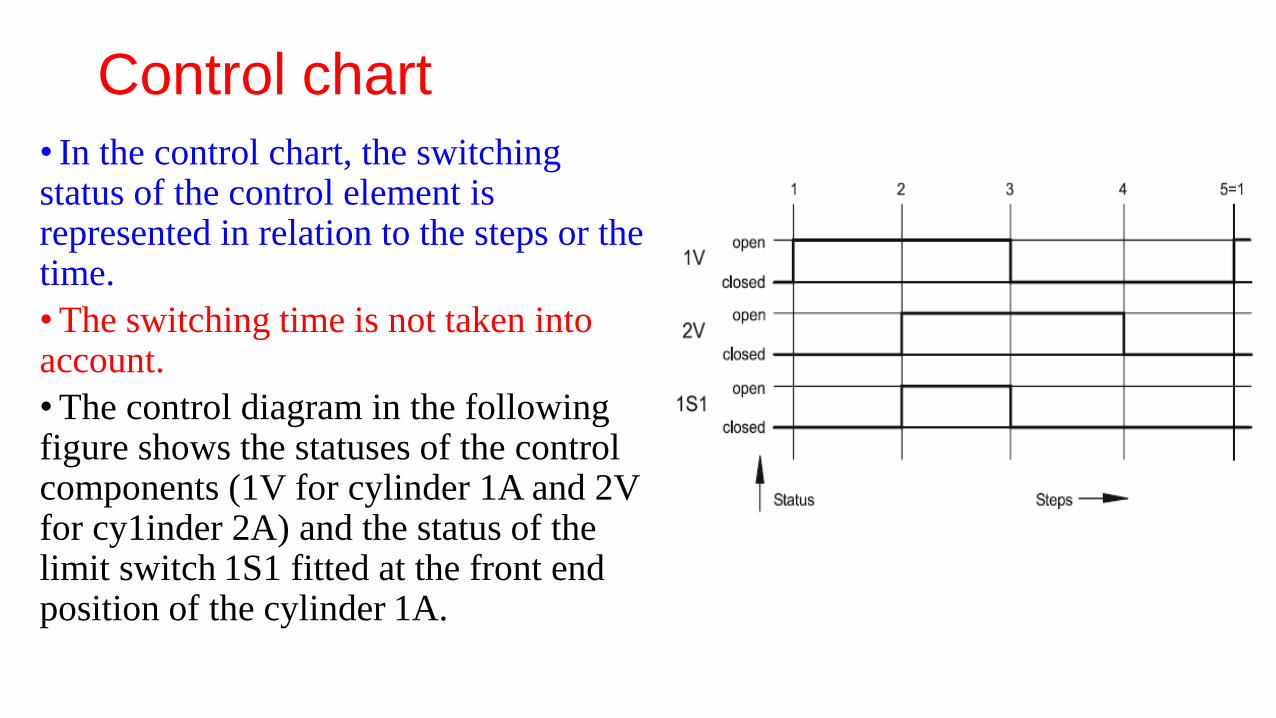
• In the control chart, the switching status of the control element is represented in relation to the steps or the time.
•The switching time is not taken into account.
•The control diagram in the following figure shows the statuses of the control components (1V for cylinder 1A and 2V for cy1inder 2A) and the status of the limit switch 1S1 fitted at the front endposition of the cylinder 1A.
Function diagram
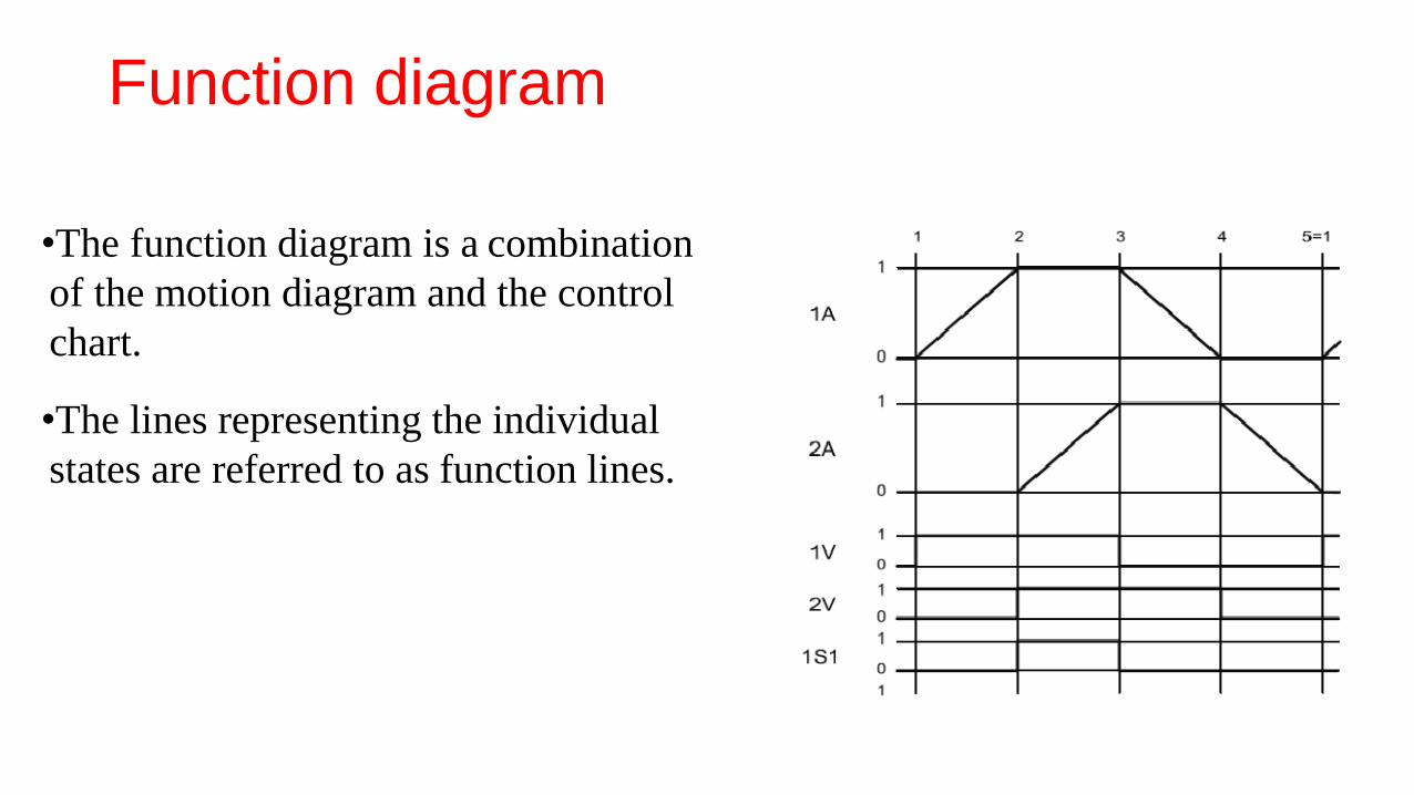
•The function diagram is a combination
of the motion diagram and the control
chart.
•The lines representing the individual
states are referred to as function lines.
Function diagram
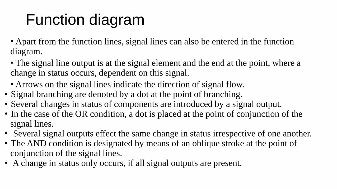
• Apart from the function lines, signal lines can also be entered in the function diagram.
• The signal line output is at the signal element and the end at the point, where a change in status occurs, dependent on this signal.
• Arrows on the signal lines indicate the direction of signal flow.• Signal branching are denoted by a dot at the point of branching. • Several changes in status of components are introduced by a signal output. • In the case of the OR condition, a dot is placed at the point of conjunction of the
signal lines.• Several signal outputs effect the same change in status irrespective of one another. • The AND condition is designated by means of an oblique stroke at the point of
conjunction of the signal lines.• A change in status only occurs, if all signal outputs are present.
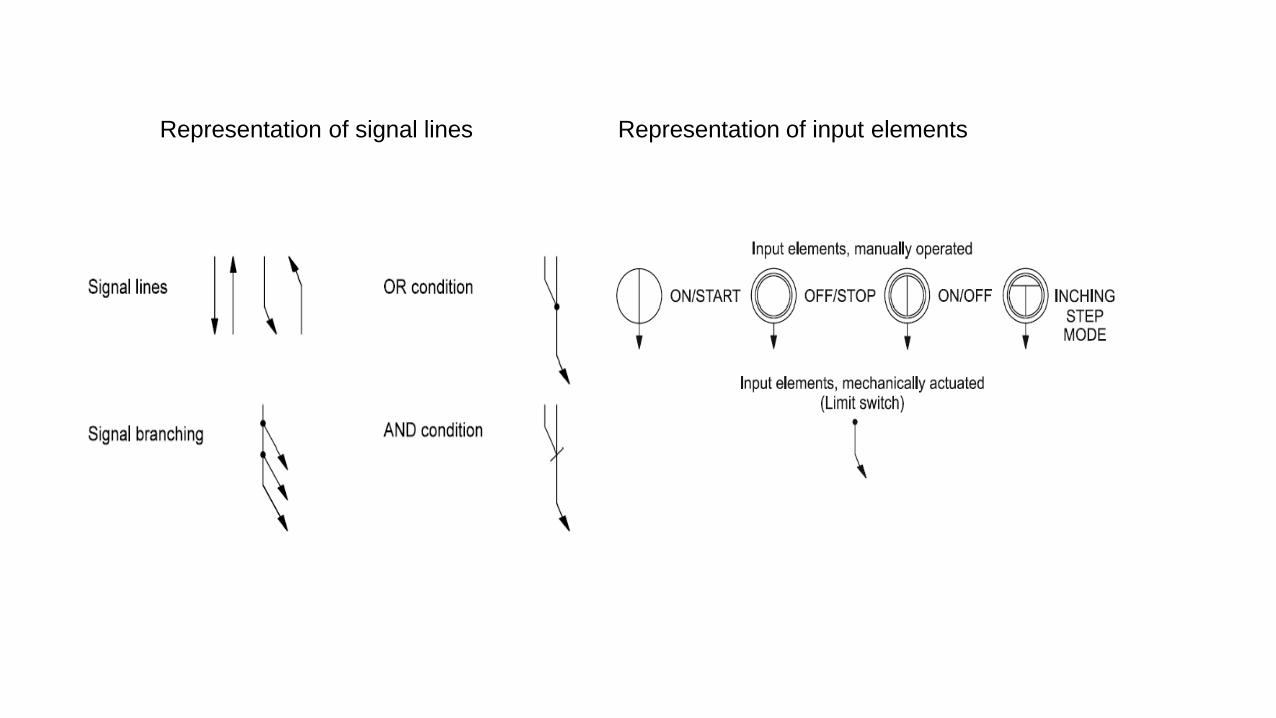
Representation of signal lines Representation of input elements
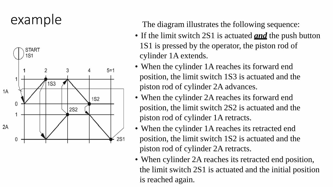
example The diagram illustrates the following sequence:
• If the limit switch 2S1 is actuated and the push button
1S1 is pressed by the operator, the piston rod of
cylinder 1A extends.
• When the cylinder 1A reaches its forward end
position, the limit switch 1S3 is actuated and the
piston rod of cylinder 2A advances.
• When the cylinder 2A reaches its forward end
position, the limit switch 2S2 is actuated and the
piston rod of cylinder 1A retracts.
• When the cylinder 1A reaches its retracted end
position, the limit switch 1S2 is actuated and the
piston rod of cylinder 2A retracts.
• When cylinder 2A reaches its retracted end position,
the limit switch 2S1 is actuated and the initial position
is reached again.
Abbreviated notation
•Abbreviated notation is another possibility of representing motion sequences. In this case, the cylinder designations 1A, 2A, etc. are used in the sequence.
•The signal for advancing is designated using a ‘+’ and the signal for retracting using a ‘-‘.
• The sequence 1A+ 2A+ 2A- 1A- is to be read as follows: Cylinder 1A advances, cylinder 2A advances, cylinder 2A retracts, cylinder 1A retracts. Sequential movements are written consecutively.• The sequence 1A+ 2A+ 2A-
1A-is to be read as:
• Cylinder 1A advances, cylinder 2A advances and cylinder 1A retracts, cylinder 2A retracts. Simultaneous movements are written vertically
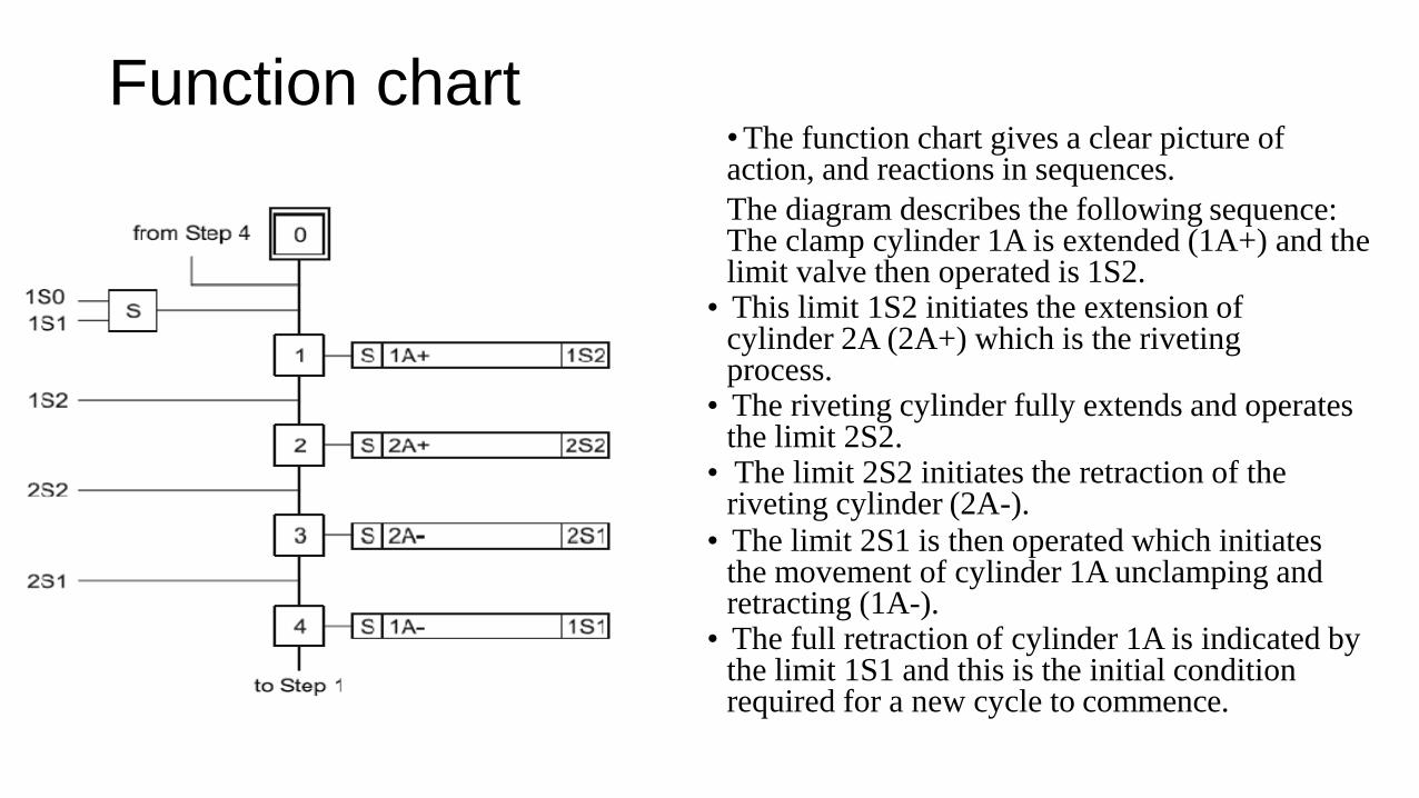
Function chart•The function chart gives a clear picture of action, and reactions in sequences.
The diagram describes the following sequence: The clamp cylinder 1A is extended (1A+) and the limit valve then operated is 1S2.
• This limit 1S2 initiates the extension of cylinder 2A (2A+) which is the rivetingprocess.
• The riveting cylinder fully extends and operates the limit 2S2.
• The limit 2S2 initiates the retraction of the riveting cylinder (2A-).
• The limit 2S1 is then operated which initiates the movement of cylinder 1A unclamping and retracting (1A-).
• The full retraction of cylinder 1A is indicated by the limit 1S1 and this is the initial condition required for a new cycle to commence.
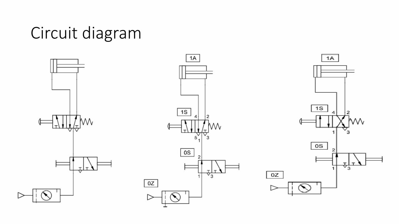
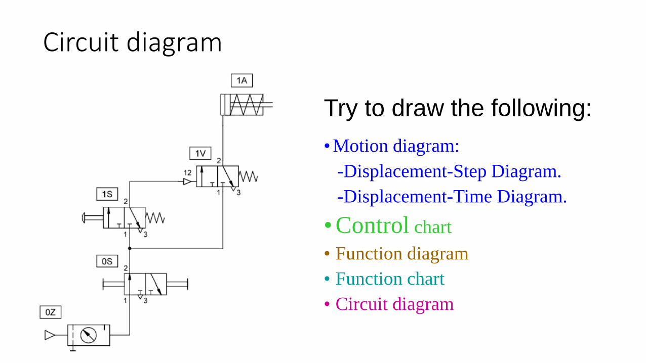
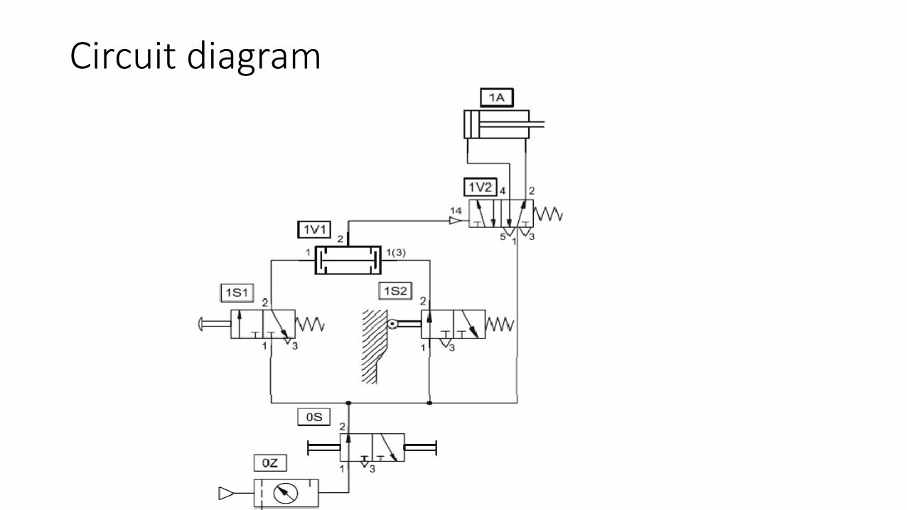
Circuit diagram
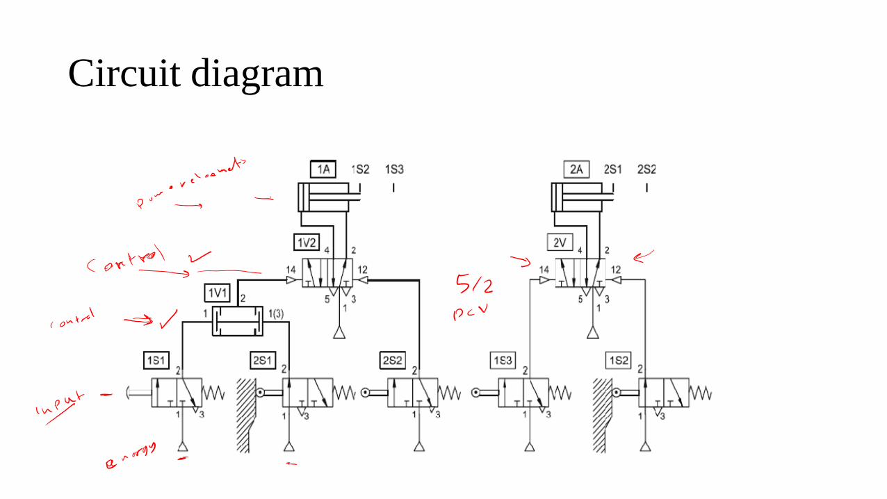
• The circuit diagram shows signal flow and the relationship between components and the air connections.
• There is no mechanical layout representation with the circuit diagram.
• The circuit is drawn with the energy flow from the bottom to the top.
• The various levels of a circuit include the energy source, signal inputs, signal processing, control elements and the actuators.
• The position of the limit valves are marked at the actuator.
• Components and lines are identified by the component numbering system and the port (way) connection numbers.
• These allow cross reference to the components on the actual machine and make the circuit readable.
Circuit diagram
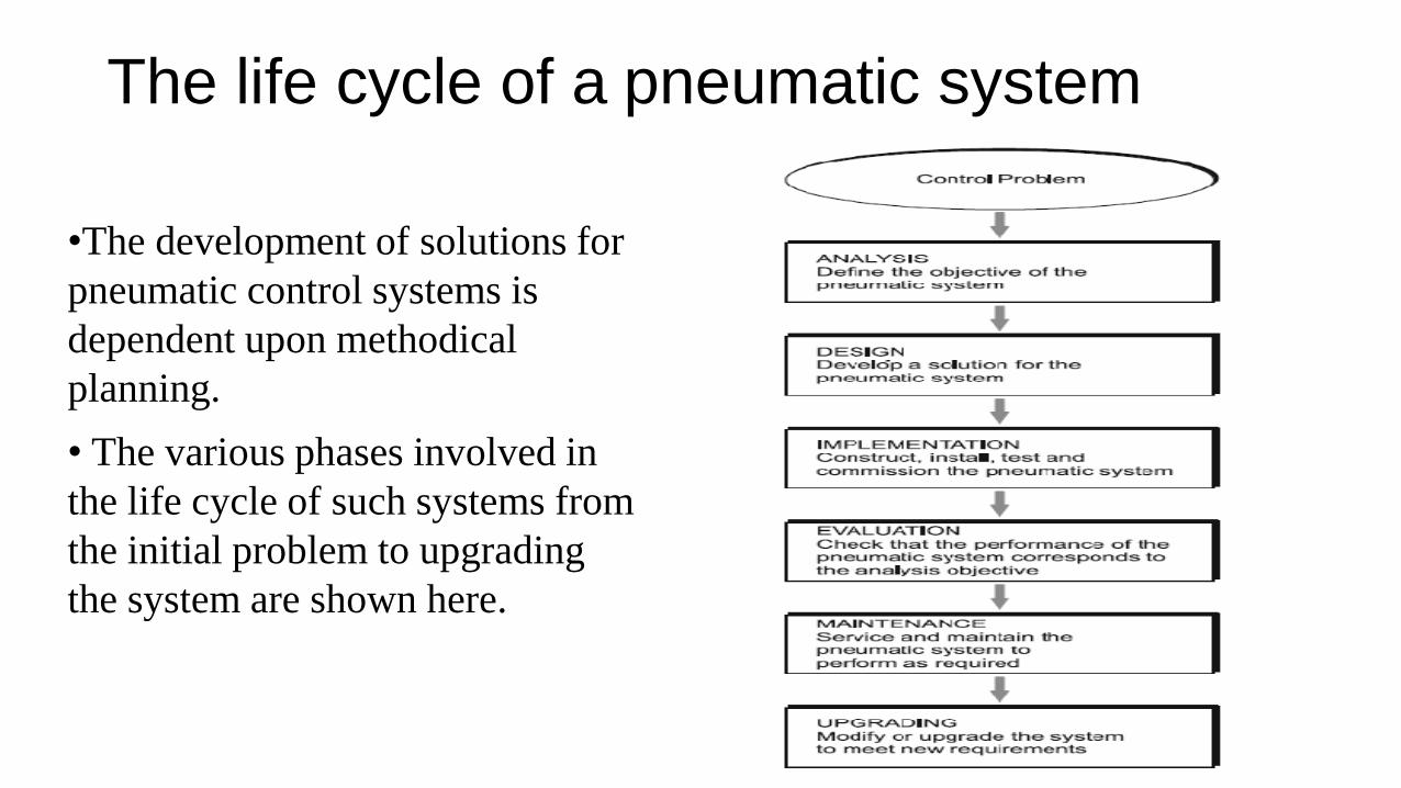
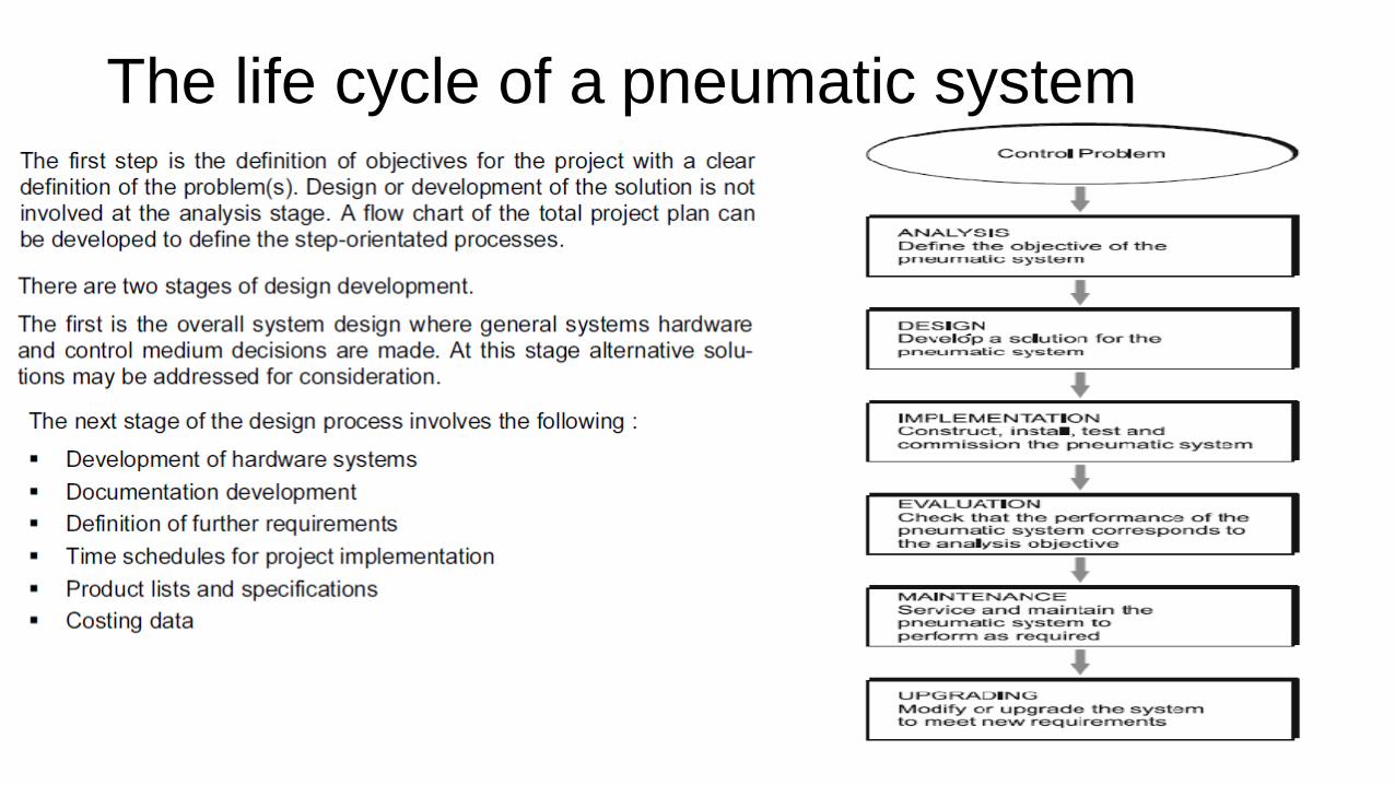
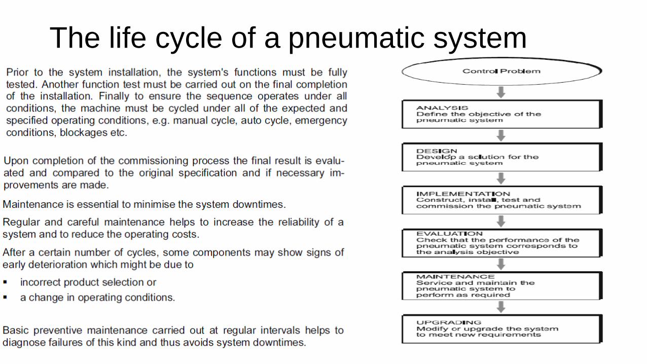
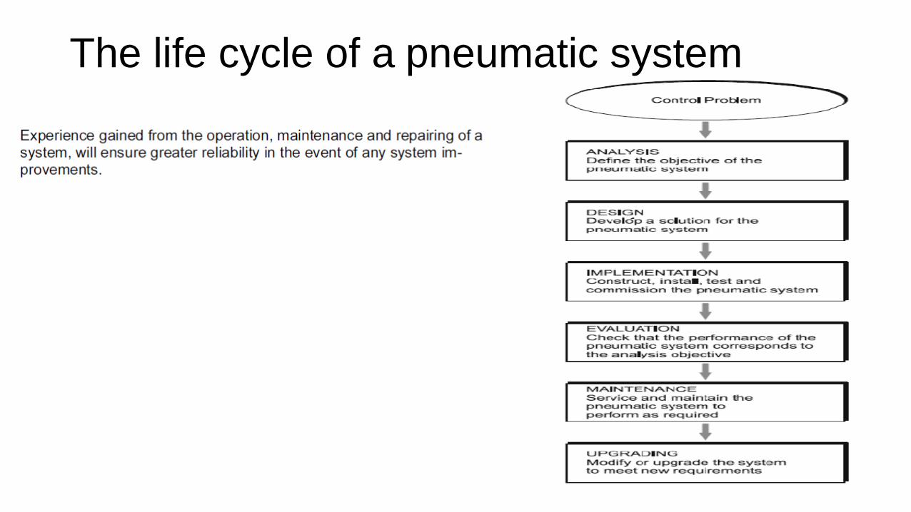
The life cycle of a pneumatic system
•The development of solutions for
pneumatic control systems is
dependent upon methodical
planning.
• The various phases involved in
the life cycle of such systems from
the initial problem to upgrading
the system are shown here.
The life cycle of a pneumatic system
The life cycle of a pneumatic system
The life cycle of a pneumatic system
Development of Pneumatic circuits• - Development of single actuator circuits:
•Direct control of a pneumatic cylinders.
• Indirect control of a pneumatic cylinders.
•Logic functions: AND, OR, …
•Memory circuit and speed control of a cylinder.
•The quick exhaust valve.
•Pressure dependent control.
•The time delay valve.
• - Development of multiple actuator circuits
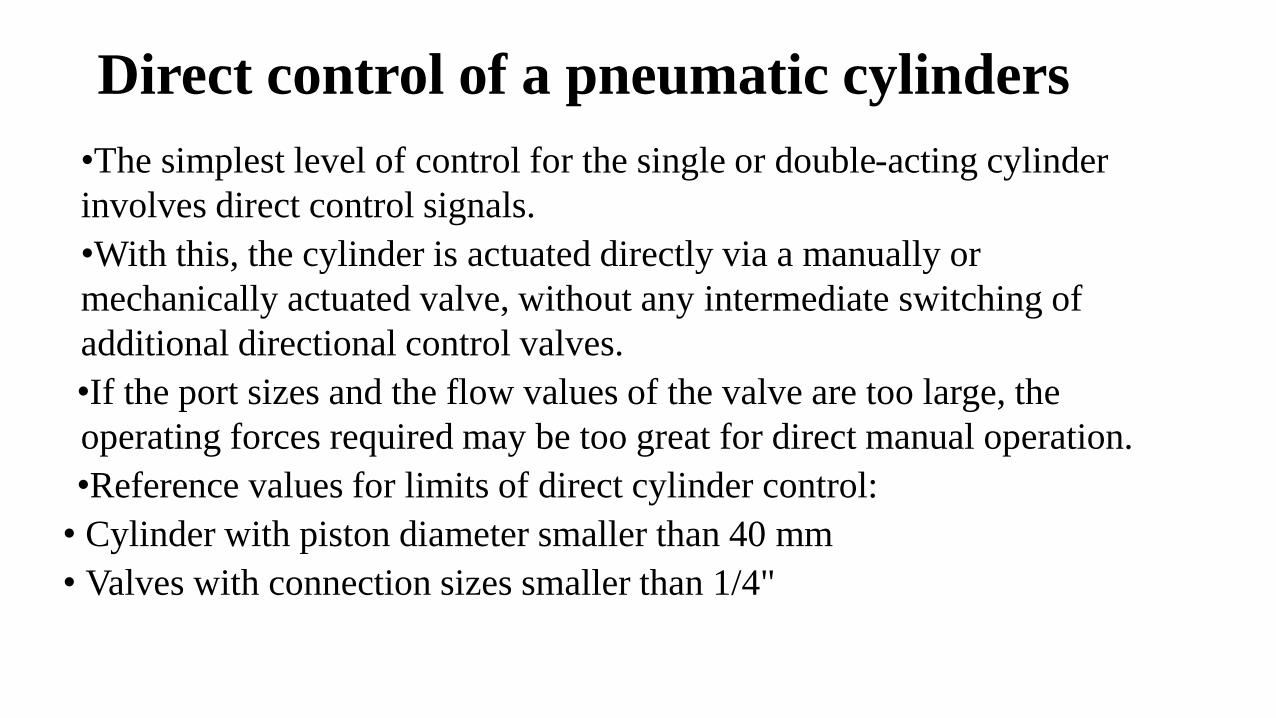
Direct control of a pneumatic cylinders
•The simplest level of control for the single or double-acting cylinder
involves direct control signals.
•With this, the cylinder is actuated directly via a manually or
mechanically actuated valve, without any intermediate switching of
additional directional control valves.
•If the port sizes and the flow values of the valve are too large, the
operating forces required may be too great for direct manual operation.
•Reference values for limits of direct cylinder control:
• Cylinder with piston diameter smaller than 40 mm
• Valves with connection sizes smaller than 1/4"
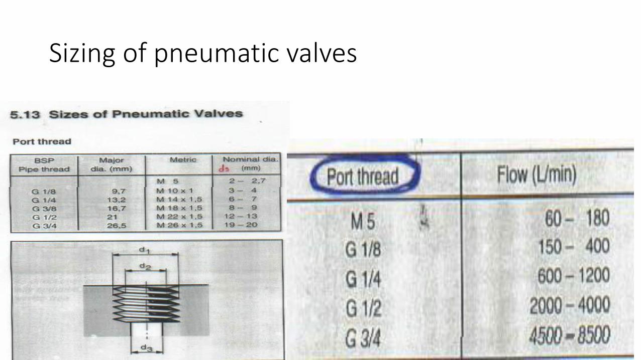
Sizing of pneumatic valves
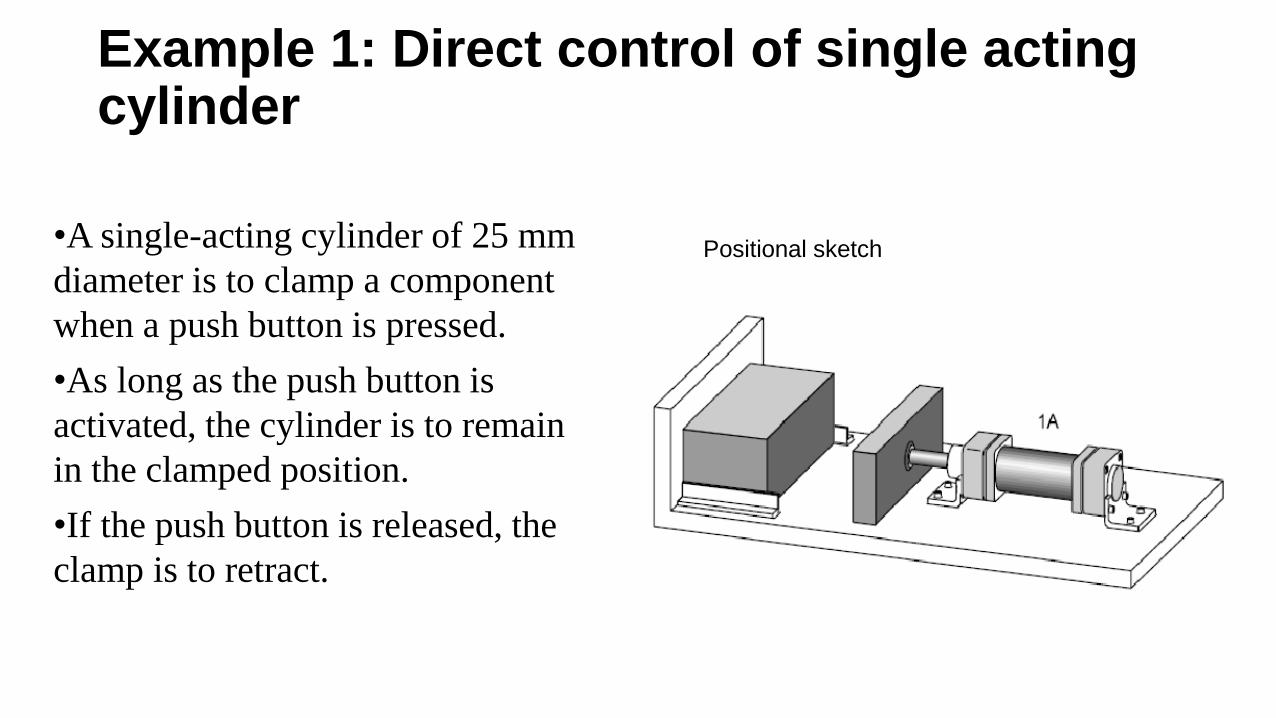
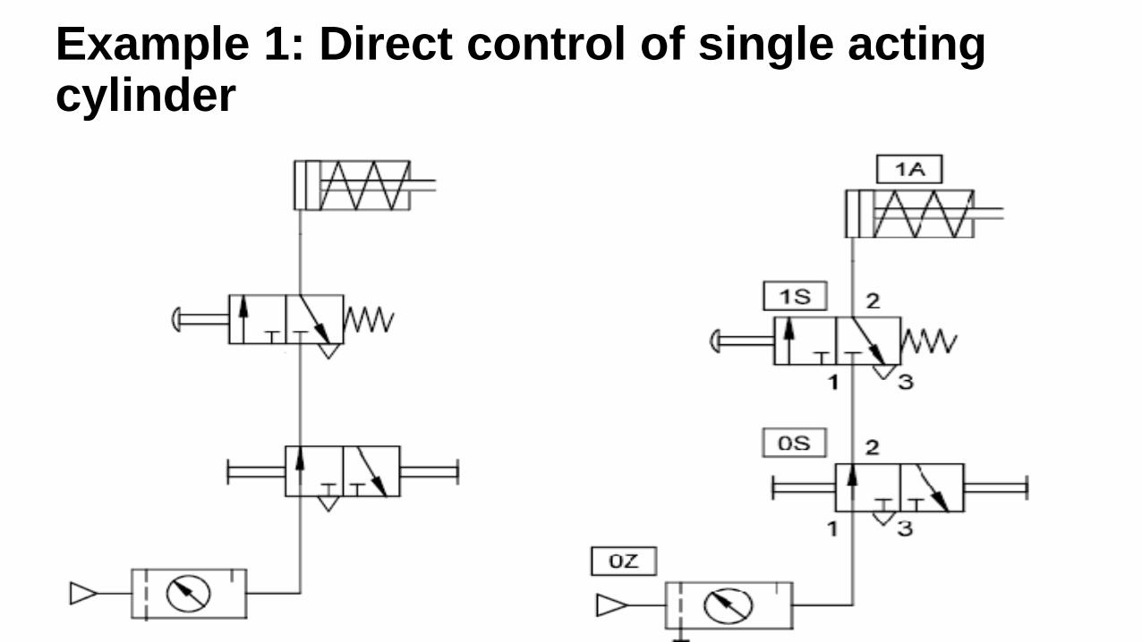
Example 1: Direct control of single acting cylinder
•A single-acting cylinder of 25 mm
diameter is to clamp a component
when a push button is pressed.
•As long as the push button is
activated, the cylinder is to remain
in the clamped position.
•If the push button is released, the
clamp is to retract.
Positional sketch
Example 1: Direct control of single acting cylinder•The control valve used for the single-acting cylinder is the 3/2-way valve.
•In this case, since the cylinder is of small capacity, the operation can be directly controlled by a push button 3/2-way directional control valve with spring return.
•On operating the push button the air passes through the valve from port 1 to 2 via the valve 1S into the piston chamber of the cylinder 1A.
•The pressure builds up and advances the piston rod against the force of the cylinder return spring.
•On release of the button, the valve spring returns the 3/2-way valve to its initial position and the cylinder retracts.
• The air returns from the cylinder via the exhaust port 3.
•Components which are the only one of their type are designated without 2 supplementary number Since the cylinder is the only working element in the circuit, it is designated 1A.
•In this and the following circuit diagrams, the service unit (0Z) and the start-up valve (0S) have also been drawn in.
Example 1: Direct control of single acting cylinder
Try to draw the following:
• Motion diagram:
-Displacement-Step Diagram.
-Displacement-Time Diagram.
• Control chart
• Function diagram
• Function chart
• Circuit diagram
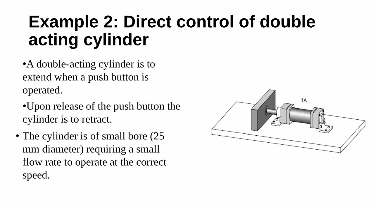
Example 2: Direct control of double acting cylinder
•A double-acting cylinder is to
extend when a push button is
operated.
•Upon release of the push button the
cylinder is to retract.
• The cylinder is of small bore (25
mm diameter) requiring a small
flow rate to operate at the correct
speed.
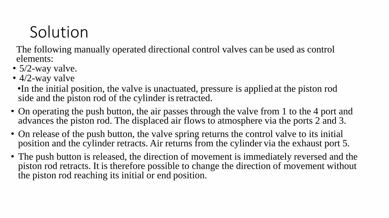
SolutionThe following manually operated directional control valves can be used as controlelements:• 5/2-way valve.• 4/2-way valve•In the initial position, the valve is unactuated, pressure is applied at the piston rod side and the piston rod of the cylinder is retracted.
• On operating the push button, the air passes through the valve from 1 to the 4 port and advances the piston rod. The displaced air flows to atmosphere via the ports 2 and 3.
• On release of the push button, the valve spring returns the control valve to its initial position and the cylinder retracts. Air returns from the cylinder via the exhaust port 5.
• The push button is released, the direction of movement is immediately reversed and the piston rod retracts. It is therefore possible to change the direction of movement without the piston rod reaching its initial or end position.
Circuit diagram
•Try to draw the following:
•Motion diagram:
-Displacement-Step Diagram.
-Displacement-Time Diagram.
• Control chart
• Function diagram
• Function chart
• Circuit diagram
Indirect control of a pneumatic cylinder
• Cylinders with a large piston diameter have a high air
requirement.
• A control element with high nominal flow rate must be used to
actuate these.
• If the force should prove too high for a manual actuation of the
valve, then an indirect actuation should be constructed, whereby a
signal is generated via a second smaller valve, which will provide
the force necessary to switch the control element.

Example 3:
•A single-acting cylinder with
a large piston diameter is to
clamp a workpiece following
actuation of a push button.
•The cylinder is to retract once
the push button is released.
Solution:
•In the initial position, the single-acting cylinder 1A is retracted. A spring return 3/2-way pneumatic valve is used to actuate the cylinder. •Connection 1 of the valve 1V is closed, connection 2 is exhausted to atmosphere via connection 3.• The valve 1S is actuated when the push button is activated and pressure is applied to the control port 12 of the control valve 1V. •The control valve 1V is actuated against spring force and is thus switched to flow. The pressure building up at the cylinder piston causes the cylinder piston rod of the single-acting cylinder to extend.• The signal at the control port 12 remains as long as the push button is operated. •Once the piston rod has reached end position, it returns only after the push button has been released.•When the push button is released, the valve 1S returns to its initial position.• Control port 12 of the control valve 1V exhausts to atmosphere and the signal is reset. •The control valve also returns to initial position.
• The return spring causes the cylinder to retract.
• The air from the cylinder chamber is exhausted to atmosphere via the control valve
Circuit diagram
Try to draw the following:
• Motion diagram:
-Displacement-Step Diagram.
-Displacement-Time Diagram.
• Control chart
• Function diagram
• Function chart
• Circuit diagram
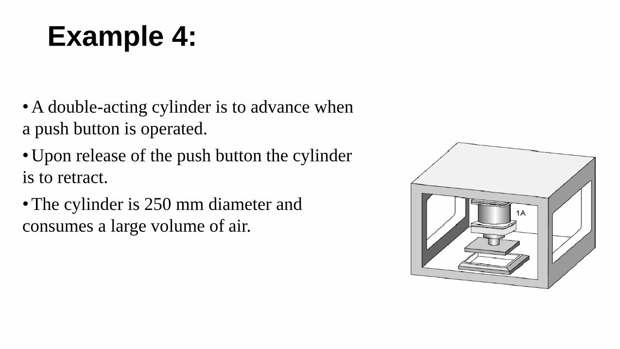
Example 4:
•A double-acting cylinder is to advance when
a push button is operated.
•Upon release of the push button the cylinder
is to retract.
•The cylinder is 250 mm diameter and
consumes a large volume of air.
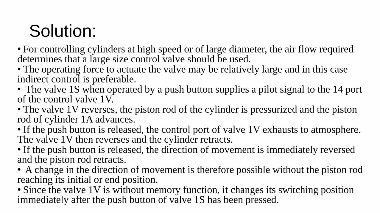
Solution:• For controlling cylinders at high speed or of large diameter, the air flow required determines that a large size control valve should be used. • The operating force to actuate the valve may be relatively large and in this case indirect control is preferable.• The valve 1S when operated by a push button supplies a pilot signal to the 14 port of the control valve 1V. • The valve 1V reverses, the piston rod of the cylinder is pressurized and the piston rod of cylinder 1A advances. • If the push button is released, the control port of valve 1V exhausts to atmosphere. The valve 1V then reverses and the cylinder retracts. • If the push button is released, the direction of movement is immediately reversed and the piston rod retracts.• A change in the direction of movement is therefore possible without the piston rod reaching its initial or end position. • Since the valve 1V is without memory function, it changes its switching position immediately after the push button of valve 1S has been pressed.
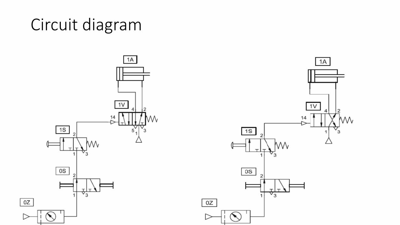
Circuit diagram
•Try to draw the following:
•Motion diagram:
-Displacement-Step Diagram.
-Displacement-Time Diagram.
• Control chart
• Function diagram
• Function chart
• Circuit diagram
Logic Functions
•The pneumatic shuttle valve and the dual pressure valve have logic
functions.
•Both have two inputs and one output each.
•The shuttle valve has the characteristic of an OR function, whereby
at least either of two inputs 1 or 1(3) are required to generate an
output at port 2 of the valve.
•In the case of the dual pressure valve, the characteristic is that of the
AND function, whereby both inputs 1 and 1(3) are required to initiate
an output 2.
Example 5:
•The piston rod of a double-acting cylinder is to advance when the 3/2-
way roller lever valve 1S2 is actuated and the push button of the 3/2-
way valve 1S1 is actuated.
• If either of these are released, then the cylinder is to return to the
initial position.
Solution:•The inputs 1 and 1(3) of the dual-pressure valve 1V1 are connected to the working ports 2 of the valves 1S1 and 1S2.
•The 3/2-way roller lever valve 1S2 is actuated by the insertion of a workpiece and then creates a signal at one input of the dual-pressure valve.
•Since only one input is actuated, the AND condition has not been fulfilled and the output of the dual-pressure valve remains closed.
•If the push button of the 3/2-way valve 1S1 is now also actuated, a signal will also be applied at the second input.
•The AND condition is now fulfilled and a signal is generated at the output 2 of the dual-pressure valve.
•The 5/2-way pneumatic valve 1V2 switches, the piston side of the cylinder is pressurized and the piston rod advances.
• If one of the two valves 1S1 or 1S2 is no longer actuated, then the AND condition will no longer be fulfilled and the signal at the output of the dual pressure valve will be reset.
•The signal pressure at the control port 14 of the control element 1V2 is exhausted to atmosphere via the reset valve 1S1 or 1S2.
•The control element 1V2 switches back. The pressure building up on the piston rod side ensures the retraction of the piston rod.
Circuit diagram
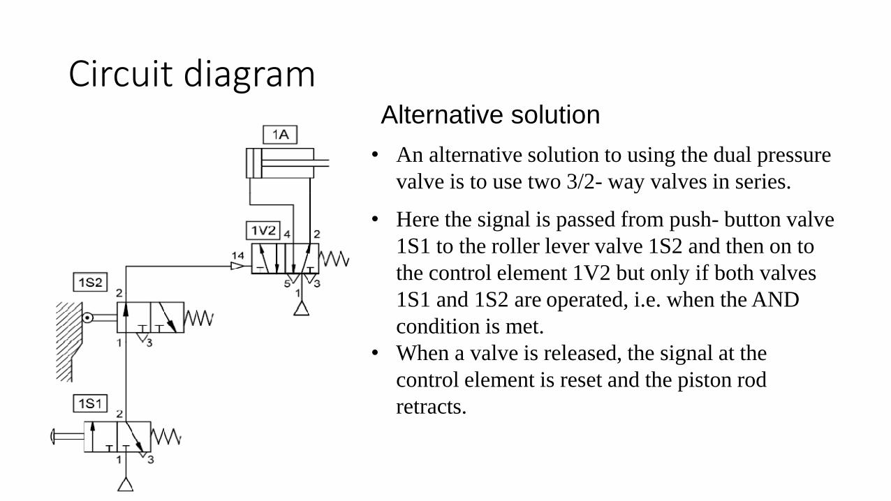
Circuit diagramAlternative solution
• An alternative solution to using the dual pressure
valve is to use two 3/2- way valves in series.
• Here the signal is passed from push- button valve
1S1 to the roller lever valve 1S2 and then on to
the control element 1V2 but only if both valves
1S1 and 1S2 are operated, i.e. when the AND
condition is met.
• When a valve is released, the signal at the
control element is reset and the piston rod
retracts.
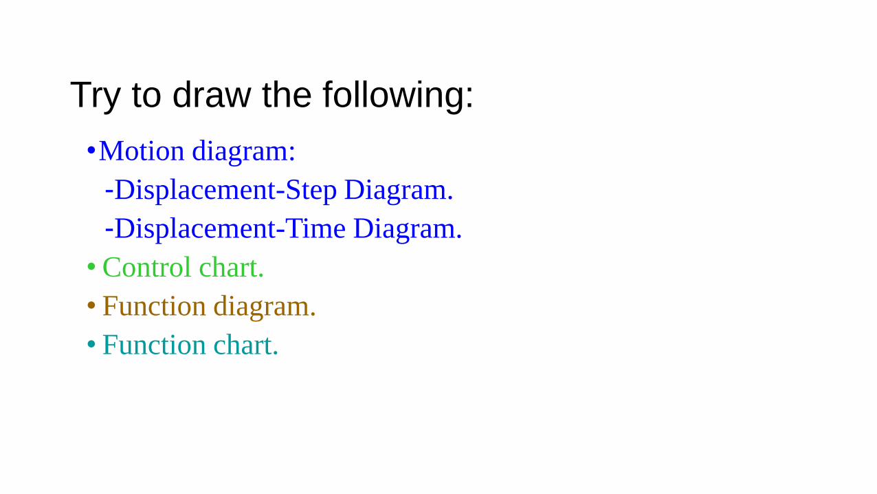
Try to draw the following:
•Motion diagram:
-Displacement-Step Diagram.
-Displacement-Time Diagram.
• Control chart.
• Function diagram.
• Function chart.

Questions


![Hydraulics and Pneumatics [302045]](https://img.pdfslide.us/doc/110x75/61dfe841a282414a66328d09/hydraulics-and-pneumatics-302045.jpg)