Embed Size (px)
Citation preview

PM 300 - 400 Planter Monitor
Troubleshooting & Connector Pin-Outs
Click on problem for troubleshooting instructions
Monitor will not power on
Row failure or HI/LOW alarm when row is planting properly
Hopper alarm does not sound when hopper is empty
Hopper alarm sounds when hopper is full
System voltage alarm
Accessory alarm sounding when shaft, fan, or flow is working
Ground speed alarm sounds with forward movement
Ground speed high alarm sounding
Self test alarmConnector Pin-outs
Battery Pin-outs
Implement Pin-outs – PM 300 & 332, PM 400
Ground Speed Pin Outs
Other Troubleshooting
FAQ’s
Glossary of Symbols

Monitor Will Not Power Up
PROBABLE CAUSE / CORRECTIVE ACTION
1. Blown Console Fuse• Check fuse (located near battery connection). If
needed, replace with 7.5 A fuse maximum. If fuseblows again, check all harnesses for pinches orbreaks that may cause power short to ground.
2. Poor Battery Connection• Be sure connections are clean and tight. Inspect
harness for damage.3. Low Battery Voltage
• Console voltage must be at least 10v. If low,recharge or replace battery.
4. Defective Console Console is damaged. Contact your dealer
BACK TO TROUBLESHOOTING MENU

Row Failure or HI/LOW Alarm WhenRow is Planting Properly
PROBABLE CAUSE / CORRECTIVE ACTION
Seed sensor coated with dirt• Clean sensor using a dry bottle brush
Faulty sensor or harness• Trigger sensor while observing troubleshooting LED. If sensor
does not have LED, swap harness connection with adjacentsensor to determine if sensor or harness is damaged. Replacesensor or harness.
Defective console• Console is damaged. Contact your dealer.
BACK TO TROUBLE SHOOTING MENU

Hopper Alarm Does Not SoundWhen Hopper is Empty
PROBABLE CAUSE / CORRECTIVE ACTION
Faulty sensor or harness open.• Swap harness connection with another sensor to determine if
sensor or harness is damaged. Use service screen if anothersensor is not available. Replace sensor or repair harness.
Defective console• Console is damaged. Contact your dealer.
BACK TO TROUBLE SHOOTING MENU

Hopper Alarm Sounds WhenHopper is Full
PROBABLE CAUSE / CORRECTIVE ACTION
Faulty sensor or harness open.• Swap harness connection with another sensor to determine if
sensor or harness is damaged. Use service screen if anothersensor is not available. Replace sensor or repair harness.
Defective console• Console is damaged. Contact your dealer.
BACK TO TROUBLE SHOOTING MENU

System Voltage Alarm
PROBABLE CAUSE / CORRECTIVE ACTION
Low battery voltage• Console voltage must be at least 10 V. If low, recharge or replace
battery. Poor battery connection
• Be sure connections are clean and tight. Inspect harness fordamage.
Damaged harness• Check all harnesses for pinches or breaks that may cause power
or 8 V-sensor power short to ground.
BACK TO TROUBLE SHOOTING MENU

Accessory Alarm Sounding WhenShaft, Fan, or Flow is Working
PROBABLE CAUSE / CORRECTIVE ACTION
Sensor failure• Shaft, fan, or flow sensor not operation. Replace defective
sensors. Wrong calibration number
• Sensor calibration number is incorrect. Check calibration numberin accessory setup screen.
Incorrect limits• Sensor limits are incorrect. Check limits in accessory setup
screen. Defective console
• Console is damaged. Contact your dealer.
BACK TO TROUBLE SHOOTING MENU

Ground Speed Alarm Sounds WithForward Movement
PROBABLE CAUSE / CORRECTIVE ACTION
Ground speed sensor failure.• No ground speed sensor is detected, or planting is
detected on at least one row with no ground speed.Replace faulty ground speed sensor.
Console Failure• Console is damaged. Contact your dealer.
BACK TO TROUBLE SHOOTING MENU

Ground Speed High AlarmSounding
PROBABLE CAUSE / CORRECTIVE ACTION
Ground speed alarm set too low.• Set ground speed alarm limit higher or to zero to disable.
Incorrect ground speed constant• Ground speed sensor has not been calibrated, RADAR sensor
angle has changed, or incorrect sensor constant is entered. UseSPEED, AREA, DISTANCE mode to determine if speed is correct.If incorrect, recalibrate speed constant (Speed Setup Screen).
BACK TO TROUBLE SHOOTING MENU

Self Test Alarm
PROBABLE CAUSE / CORRECTIVE ACTION
Seed sensor coated with dirt.• Clean sensor using dry bottle brush
Faulty sensor or harness• Trigger sensor and observe troubleshooting LED. If
sensor does not have LED, swap harness connectionwith adjacent sensor to determine if sensor or harnessis damaged. Replace sensor or harness.
Console failure• Console is damaged. Contact your dealer.
BACK TO TROUBLE SHOOTING MENU
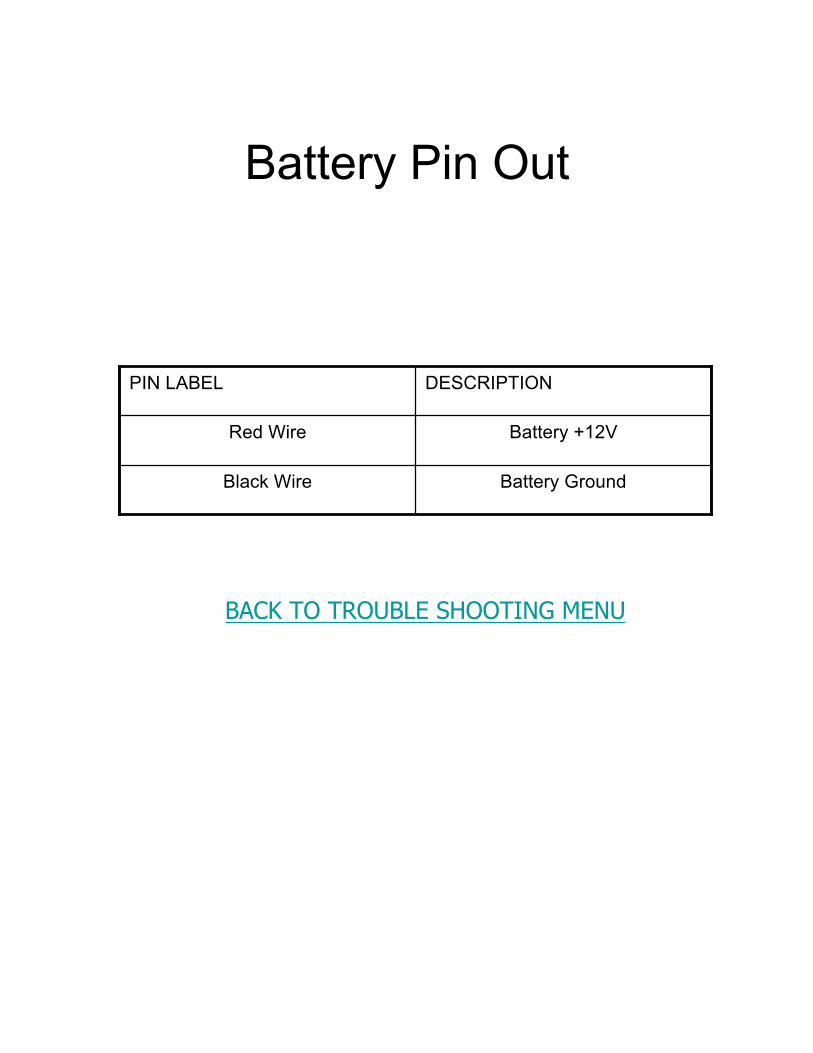
Battery Pin Out
Battery GroundBlack Wire
Battery +12VRed Wire
DESCRIPTIONPIN LABEL
BACK TO TROUBLE SHOOTING MENU

PM 300 Implement Harness
Row 16 (red / white)16
Row 15 (black / white)15
Row 14 (blue/blk)14
Row 13 (org/blk)13
Row 12 (grn/blk)12
Row 11 (red/blk)11
Row 10 (wht/blk)10
Row 9 (tan)9
Row 8 (pink)8
Row 7 (gray)7
Row 6 (violet)6
Row 5 (yellow)5
Row 4 (orange)4
Row 3 (blue)3
Row 2 (brown)2
Row 1 (green)1
DESCRIPTIONPIN #
PM 300 Implement Continued
Lift Switch (orange / red)37
RS-232 Tx (red / green)36
RS-232 Rx (blue / red)35
12V return (black)34
12V switched power (wht/red)33
8V power (red)32
Shaft / fan / flow (black / red)31
Hopper 2 (blue / white)30
Hopper 1 (green / white)29
No connection28
Sensor return (wht / blk / red)27
Sensor return (black)26
8V sensor power (red / blk/ wht)25
8V sensor power (red)24
No connection17-23
BACK TO TROUBLE SHOOTING MENU

PM 332 Implement Harness
Row 19 (black red)19
Row 18 (blue / white)18
Row 17 (green / white)17
Row 16 (red / white)16
Row 15 (black / white)15
Row 14 (blue/blk)14
Row 13 (org/blk)13
Row 12 (grn/blk)12
Row 11 (red/blk)11
Row 10 (wht/blk)10
Row 9 (tan)9
Row 8 (pink)8
Row 7 (gray)7
Row 6 (violet)6
Row 5 (yellow)5
Row 4 (orange)4
Row 3 (blue)3
Row 2 (brown)2
Row 1 (green)1
DESCRIPTIONPIN #
Lift Switch (wht)37
Row 32 (green / black / orange)36
Row 31 (red / black / green)35
Row 30 (wht / red / green)34
Row 29 (blk / red/ green )33
Row 28 (blue / blk / wht)32
Row 27 (org / blk/ wht)31
Row 26 (grn /blk / wht)30
Row 25 (blk / wht / red)29
Row 24 (orange)28
Ground right (wht / blk / red)27
Ground left (black)26
+8V snsr pwr right(red/blk/wht)25
+8V sensor power left (red)24
Row 23 (red / green)23
Row 22 (blue / red)22
Row 21 (orange / red)21
Row 20 (white / red)20
BACK TO TROUBLE SHOOTING MENU
PM 332 Implement continued
Click here for pinouts to PM 332 Implement Accessory Harness

PM 332 Implement Accessory
RS-232 Tx (neutral)9
RS-232 Rx (pink)8
Acc Return (gray)7
+12V Acc Power (purple)6
+8V Acc Power (yellow)5
Frequency (orange)4
Hopper #2 (light blue)3
Hopper #1 (brown)2
Lift Switch (light green)1
DescriptionPin #
BACK TO TROUBLE SHOOTING MENU

PM 400 Implement
Row 19 (black / red)19
Row 18 (blue / wht)18
Row 17 (green / wht)17
Row 16 (red wht)16
Row 15 (blk / wht)15
Row 14 (blue / blk)14
Row 13 (orange / blk)13
Row 12 (green / blk)12
Row 11 (red / blk)11
Row 10 (wht / blk)10
Row 9 (tan)9
Row 8 (pink)8
Row 7 (gray)7
Row 6 (violet)6
Row 5 (yellow)5
Row 4 (orange)4
row 3 (blue)3
Row 2 (brown)2
Row 1 (green)1
Implement 1
Lift switch (blk / wht/ red)37
No connection35,36
Sensor return (black)34
No Connection33
8V power (red)32
No connection30,31
Hopper 1 (wht)29
Row 24 (orange / green)28
Sensor return (black)27
Sensor return (black)26
+8V sensor pwr right (red)25
+8V sensor pwr left (red)24
Row 23 (red / green)23
Row 22 (blue / red)22
Row 21 (orange / red)21
Row 20 (wht / red)20
continued
BACK TO TROUBLE SHOOTING MENU
Click here for pin outs to PM400 Implement 2

PM 400 Implement 2
Snsr return (wht/blk/red)26
8V snsr pwr (red)25
8V snsr pwr (red/blk/wht)24
No connection13-23
Row 36 (green / blk)12
Row 35 (red / blk)11
Row 34 (wht / blk)10
Row 33 (tan)9
Row 32 (pink)8
Row 31 (gray)7
Row 30 (violet)6
Row 29 (yellow)5
Row 28 (orange)4
Row 27 (blue)3
Row 26 (brown)2
Row 25 (green)1
No connection37
RS-232 Tx (red/wht)36
RS-232 Rx (blue/wht)35
12V return (black)34
12V switched pwr (grn/wht33
8V power (red)32
Shaft / fan / flow (blk/wht)31
Hopper 2 (blue/blk)30
Hopper 1 (orange/blk)29
No connection28
Sensor return (black)27
Implement 2 continued
BACK TO TROUBLE SHOOTING MENU

Ground Speed
Sense (white)4
Power (red)3
Signal (green)2
Ground (black)1
DescriptionPIN#
BACK TO TROUBLE SHOOTING MENU

Frequently Asked QuestionsPM300/400
• Q: Can I use a RPM sensor such as a reluctance sensor for my ground speedinput?A: No, the PM300/400 cannot read the signal produced from a reluctance sensor. Itcan only read a square wave/digital signal. For best results, use either ourRVSII/RVSIII, iSpeed, or Hall Effect Sensor.
• Q: On my PM400, how many rows can I put on J1 by itself?A: J1 can take 24 row inputs. Any more, and you’ll have to put extra rows on J2.However, the PM400 can only monitor 48 rows at a time. If you want to monitormore rows, try our Seed Manager SE for population or DjASM II for no population.The PM300 can take 16 rows on J1.
• Q: My PM300 / 400 won’t stop counting acres and is only showing speed.A: You could be in Speed and Area mode. Push Operate to show normal operation.Speed and Area mode should not be used unless you are using the monitor for anon-planting operation, cultivating, plowing, disking, etc.
• Q: Is there a quick way to clear the acres off the monitor?A: Yes, use the up and down arrows next to the display to make sure the acreaccumulator is at the top of the screen. Then, push and hold Escape for threeseconds, and it will clear.
• Q: My ground speed sensor has malfunctioned. Can I put a manual speed in?A: Yes, push the ground speed button, scroll down to the manual speed, and entera speed you typically run. Keep in mind, you need to maintain the entered speedyou enter to maintain proper acre counter, population, and spacing. If you losespeed as you plant, an alarm will sound and a tractor with an X through it will bedisplayed. When this happens, at the bottom of the screen the number 00.0 will bea highlighted. Use the up and down arrow keys to the right of the display to changeto your normal planting speed, and then press enter. This will automatically put youinto a manual mode. Once this is completed, press the operate key and startplanting.
BACK TO TROUBLE SHOOTING MENU
Other frequently asked questions

Frequently Asked QuestionsPM300/400 (continued)
• Q: Is there any way to adjust the brightness of the screen to make it is easierto read?A: Yes, press the display and service button. Using the up and down arrow keys tothe right of the display scroll down to the light bulb, press enter, and use the up anddown buttons to adjust brightness.
• Q: Is there any way to change the volume of the alarm?A: Yes, press the Display and Service button. Using the up and down arrow keysscroll down to the speaker, press Enter, and use the up/down arrows to adjust thevolume. Once you have found a tolerable level, press Enter to save your settings.Then press the Operate key to resume planting.
• Q: Can I change the font size on the display?A: Yes, press the Display and Service button. Using the up/down arrow keys, scrolldown to the magnifying glass, and press Enter. When you found the font size youlike, press Enter to save, then press Operate to resume planting.
• Q: Can I use the PM300 / 400 to count acres only?A: Yes, push the Speed and Area button to access one of the different counters.There are four different counters to choose from, and there will be a stop and startfunction for each counter. After selecting the counter you want, use the up/downarrow keys to the right of the display, and press Enter to stop/start the selected acrecounter. To clear all totals, press the Clear button.
• Q: Can the PM300 / 400 monitor fertilizer drops as well as seed drops?A: Yes, press the Accuracy setup button. Using the up/down arrow keys to the rightof the display, select what you want the monitor to do and calibrate accordingly.The PM 300/400 can also monitor a shaft and fan sensor
BACK TO TROUBLE SHOOTING MENU

Glossary of Symbols
Alarm All RowsFailed
Area PerHour
AveragePopulation
AverageSpacing
Backlight Configuration Englishto Metric
Fan Field Area 1
Field Area 2 Flow Graphic Text HiLo Hopper Low
Minimum AverageMaximum Population
Minimum AverageMaximum Seeds per
Distance
Minimum AverageMaximum Spacing
No Flow No Speed
PlanterLifted
PopulationAdjust
PopulationRow Scan
Reset ResponseRate
BACK TO TROUBLE SHOOTING MENU
Symbols Continued

Glossary of Symbols(Continued)
SavePassword
Security Seeds PerDistance
Seeds PerDistance Row
Scan
Shaft
Spacing RowScan
Speed Start Stop Total Area Warning
BACK TO TROUBLE SHOOTING MENU