Embed Size (px)
Citation preview
1
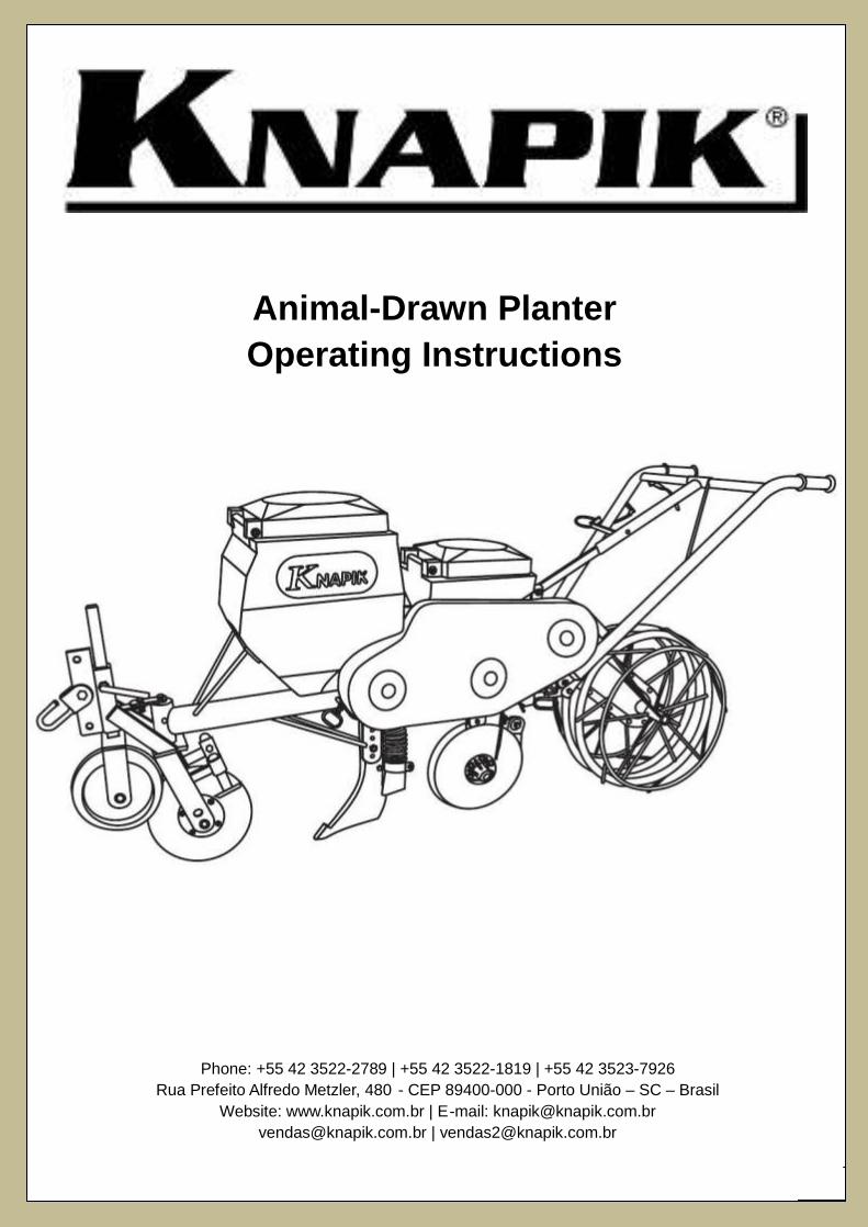
Animal-Drawn Planter
Operating Instructions
Phone: +55 42 3522-2789 | +55 42 3522-1819 | +55 42 3523-7926
Rua Prefeito Alfredo Metzler, 480 - CEP 89400-000 - Porto União – SC – Brasil
Website: www.knapik.com.br | E-mail: [email protected]
2
SUMMARY
1. OPERATOR WARNINGS..................................................................................................................................... 3
2. PLANTER PARTS................................................................................................................................................ 4
3. PLANTER ASSEMBLY ......................................................................................................................................... 5
3.1. CARRIER WHEELS INSTALLATION…………………………………………………….…………………………… 6
3.2. PLANTER FRONT UNIT ASSEMBLY…………………………………………………..…………………………….. 6
3.3. TIGHTENING THE ENGAGEMENT CLAMP............................. ........................................................................ 6
3.3.1. Adjusting the Front Unit……………......................................................................................... ........................ 7
3.4. FITTING THE GROUND WHEELS IN THE ARMORED UNIT…………............................................................ 7
3.5. FITTING THE ARMORED UNIT WITH GROUND WHEELS IN THE MAIN FRAME…………………………... 8
3.5.1. Fitting The Adjustment Bar In The Support Guide…………..…………………………………………………... 8
3.6. HANDLE ASSEMBLY......................................................................................................... ................................ 9
3.6.1. Handle Height Adjustment………......................................................... ........................................................... 10
4. FERTILIZER DISTRIBUTION............................................................................................................................... 11
4.1. FERTILIZER AMOUNT ADJUSTING……….……………................................................................................... 11
5. FURROW OPENER.............................................................................................................................................. 12
6. SEEDS DISTRUBUTION...................................................................................................................................... 12
7. DOUBLE DISC FURROW OPENER WITH OFFSET DISCS............................................................................... 12
8. SEED HOPPER STEPS OF ASSEMBLY ............................................................................................................. 13
8.1. REMOVING THE ENTIRE SEED HOPPER....................................................................................................... 13
8.2. ROLLER BOX..................................................................................................................................................... 14
9. ADJUSTMENT OF CHAINS AND SPROCKET.................................................................................................... 14
9.1. TABLE FOR CONCEPTS OF ADJUSTING OF SEEDS QUANTITY - GRAINS PER METER…………………. 15
10. TRANSPORTATION OF MACHINE ................................................................................................................... 16
11. STARTING THE PLANTING ............................................................................................................................... 16
12. DISTANCE BETWEEN THE ANIMAL AND THE PLANTER ............................................................................. 16
13. LUBRICATING NIPPLES POINTS ..................................................................................................................... 17
14. FINAL CONSIDERATIONS ................................................................................................................................ 17
3
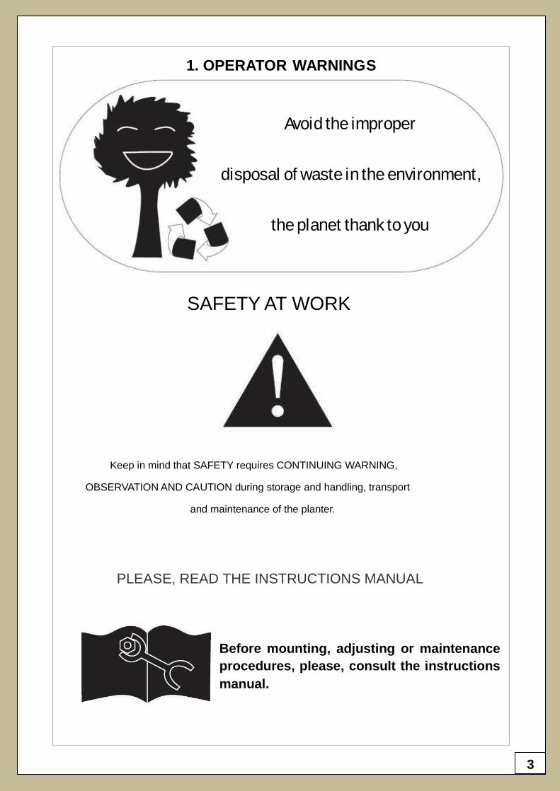
SAFETY AT WORK
Keep in mind that SAFETY requires CONTINUING WARNING,
OBSERVATION AND CAUTION during storage and handling, transport
and maintenance of the planter.
PLEASE, READ THE INSTRUCTIONS MANUAL
Before mounting, adjusting or maintenance
procedures, please, consult the instructions
manual.
1. OPERATOR WARNINGS
Avoid the improper
disposal of waste in the environment,
the planet thank to you
4
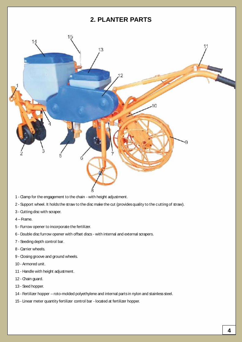
2. PLANTER PARTS
1 - Clamp for the engagement to the chain - with height adjustment.
2 - Support wheel. It holds the straw to the disc make the cut (provides quality to the c utting of straw).
3 - Cutting disc with scraper.
4 – Frame.
5 - Furrow opener to incorporate the fertilizer.
6 - Double disc furrow opener with offset discs - with internal and external scrapers.
7 - Seeding depth control bar.
8 - Carrier wheels.
9 - Closing groove and ground wheels.
10 - Armored unit.
11 - Handle with height adjustment.
12 - Chain guard.
13 - Seed hopper.
14 - Fertilizer hopper – roto-molded polyethylene and internal parts in nylon and stainless steel.
15 - Linear meter quantity fertilizer control bar - located at fertilizer hopper.
5
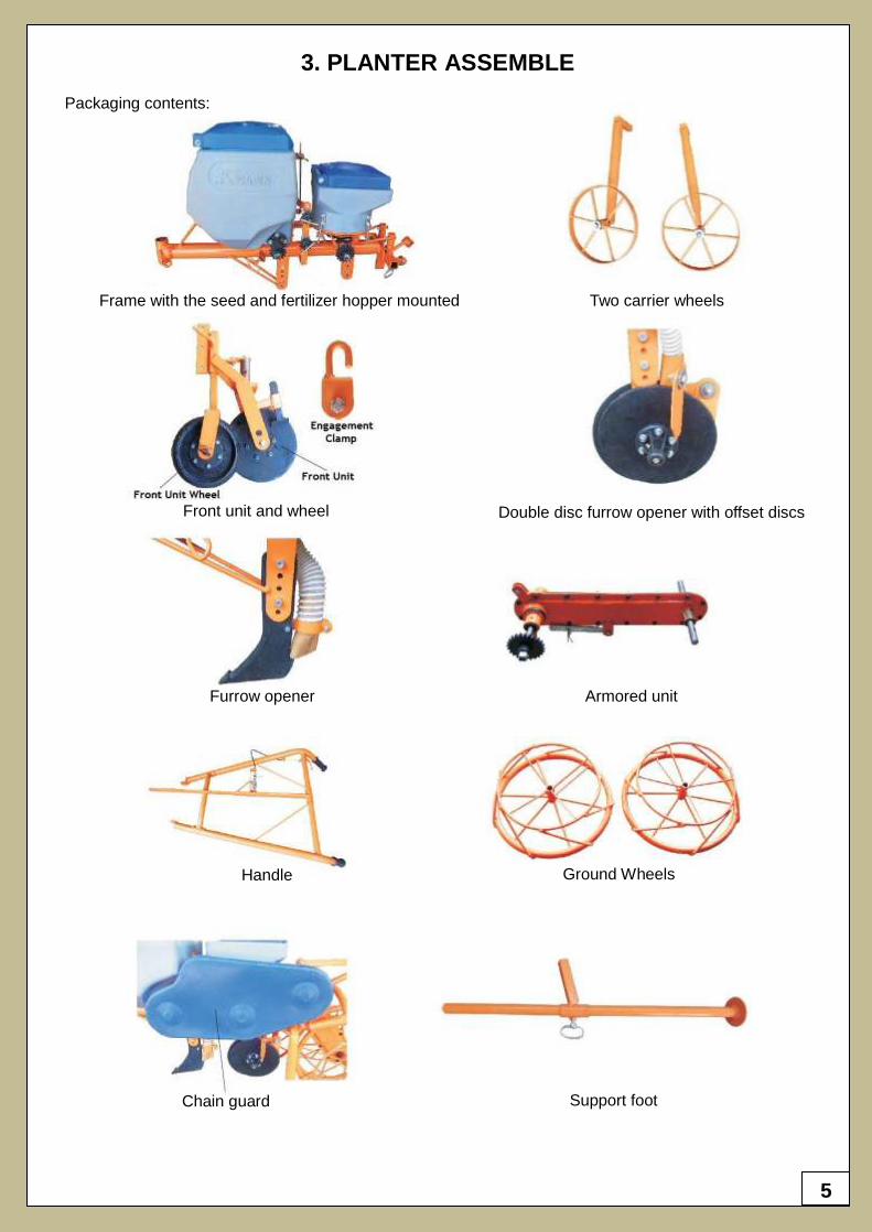
3. PLANTER ASSEMBLE
Packaging contents:
Frame with the seed and fertilizer hopper mounted Two carrier wheels
Front unit and wheel Double disc furrow opener with offset discs
Furrow opener Armored unit
Handle Ground Wheels
Chain guard Support foot
6
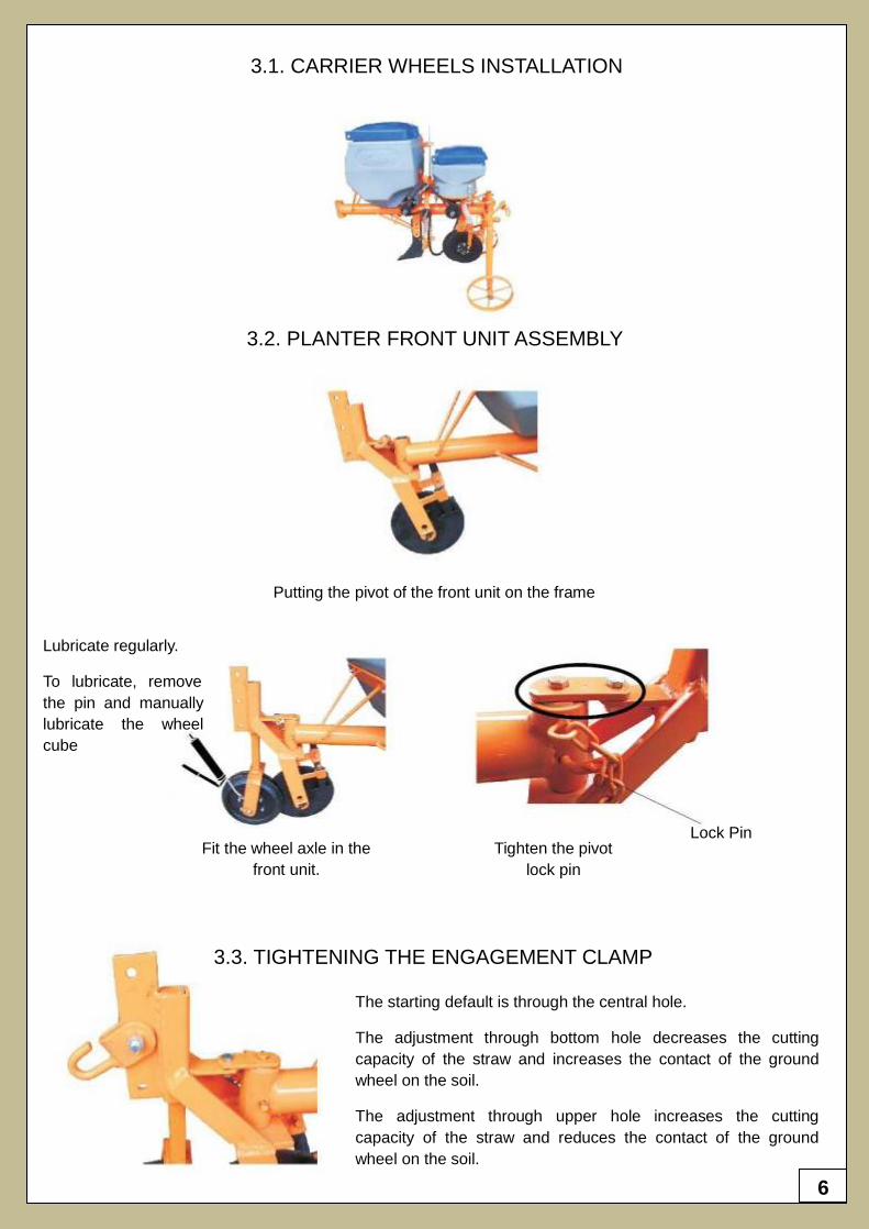
3.1. CARRIER WHEELS INSTALLATION
Putting the pivot of the front unit on the frame
Lubricate regularly.
To lubricate, remove
the pin and manually
lubricate the wheel
cube
Fit the wheel axle in the
front unit.
Tighten the pivot
lock pin
Lock Pin
The starting default is through the central hole.
The adjustment through bottom hole decreases the cutting
capacity of the straw and increases the contact of the ground
wheel on the soil.
The adjustment through upper hole increases the cutting
capacity of the straw and reduces the contact of the ground
wheel on the soil.
3.3. TIGHTENING THE ENGAGEMENT CLAMP
3.2. PLANTER FRONT UNIT ASSEMBLY
7
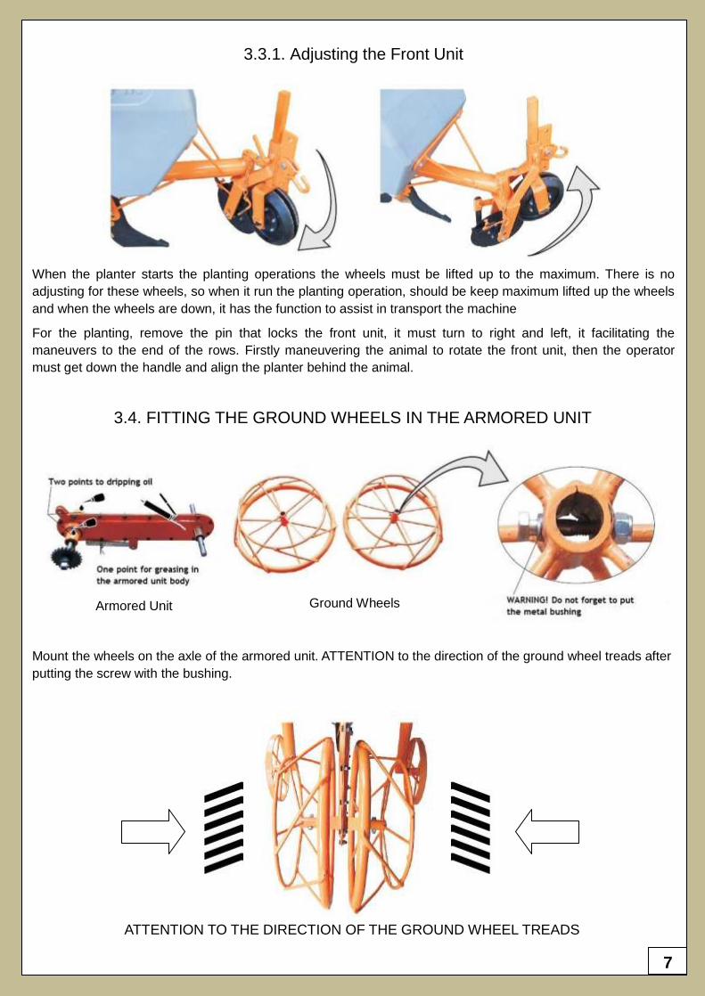
3.3.1. Adjusting the Front Unit
When the planter starts the planting operations the wheels must be lifted up to the maximum. There is no
adjusting for these wheels, so when it run the planting operation, should be keep maximum lifted up the wheels
and when the wheels are down, it has the function to assist in transport the machine
For the planting, remove the pin that locks the front unit, it must turn to right and left, it facilitating the
maneuvers to the end of the rows. Firstly maneuvering the animal to rotate the front unit, then the operator
must get down the handle and align the planter behind the animal.
3.4. FITTING THE GROUND WHEELS IN THE ARMORED UNIT
Armored Unit Ground Wheels
Mount the wheels on the axle of the armored unit. ATTENTION to the direction of the ground wheel treads after
putting the screw with the bushing.
ATTENTION TO THE DIRECTION OF THE GROUND WHEEL TREADS
8
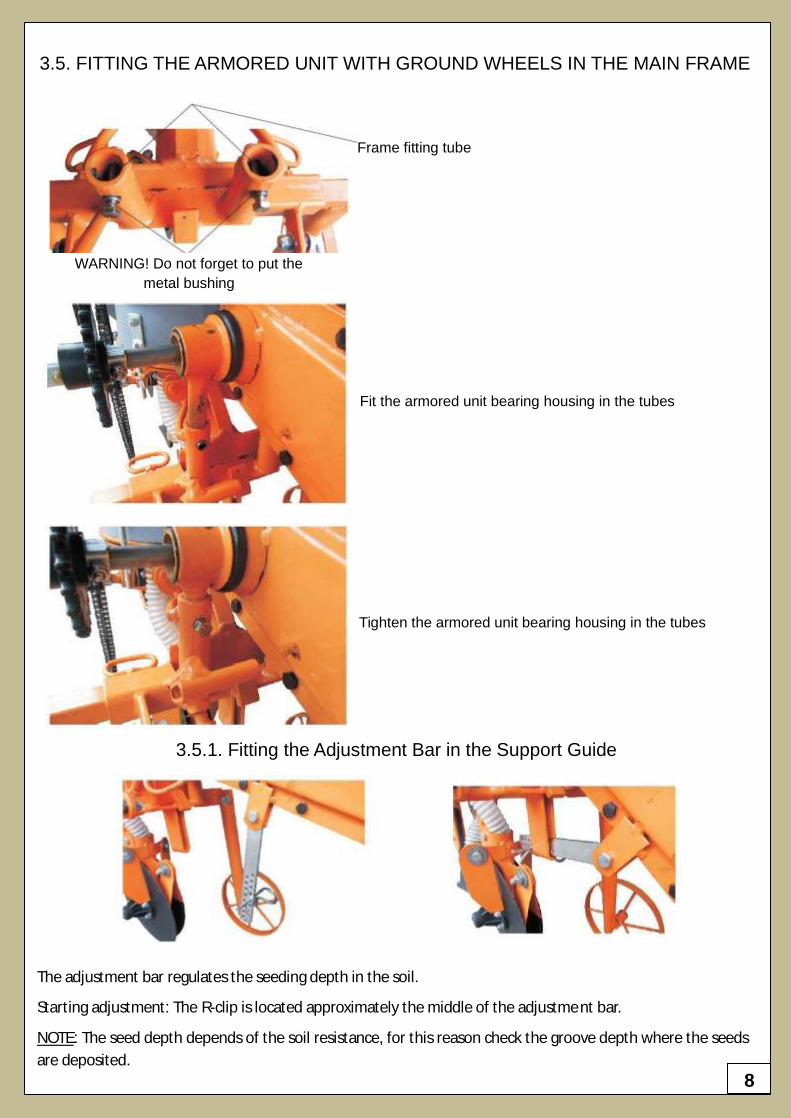
3.5. FITTING THE ARMORED UNIT WITH GROUND WHEELS IN THE MAIN FRAME
Frame fitting tube
WARNING! Do not forget to put the
metal bushing
Fit the armored unit bearing housing in the tubes
Tighten the armored unit bearing housing in the tubes
3.5.1. Fitting the Adjustment Bar in the Support Guide
The adjustment bar regulates the seeding depth in the soil.
Starting adjustment: The R-clip is located approximately the middle of the adjustme nt bar.
NOTE: The seed depth depends of the soil resistance, for this reason check the groove depth where the seeds
are deposited.
9
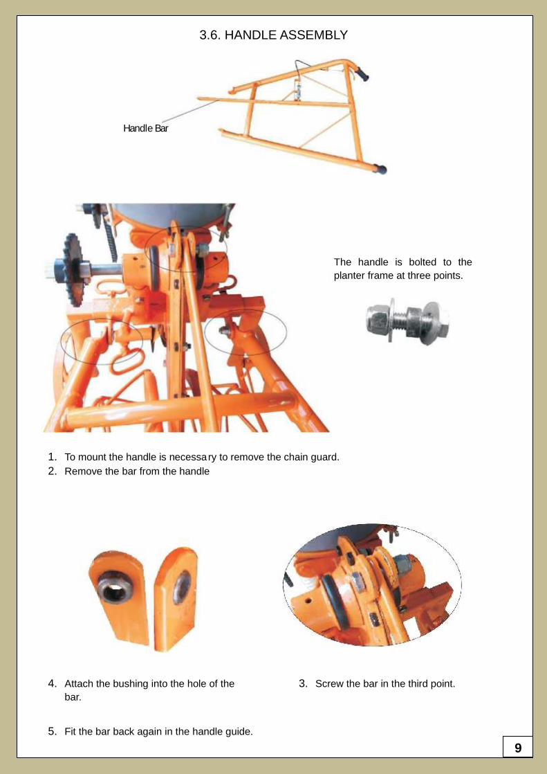
3.6. HANDLE ASSEMBLY
The handle is bolted to the
planter frame at three points.
1. To mount the handle is necessary to remove the chain guard.
2. Remove the bar from the handle
4. Attach the bushing into the hole of the
bar.
3. Screw the bar in the third point.
5. Fit the bar back again in the handle guide.
Handle Bar
10
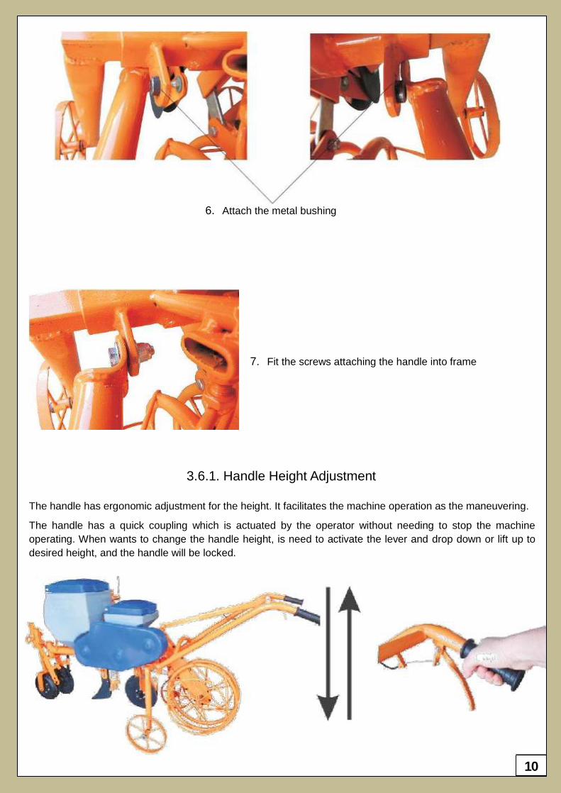
6. Attach the metal bushing
7. Fit the screws attaching the handle into frame
3.6.1. Handle Height Adjustment
The handle has ergonomic adjustment for the height. It facilitates the machine operation as the maneuvering.
The handle has a quick coupling which is actuated by the operator without needing to stop the machine
operating. When wants to change the handle height, is need to activate the lever and drop down or lift up to
desired height, and the handle will be locked.
11
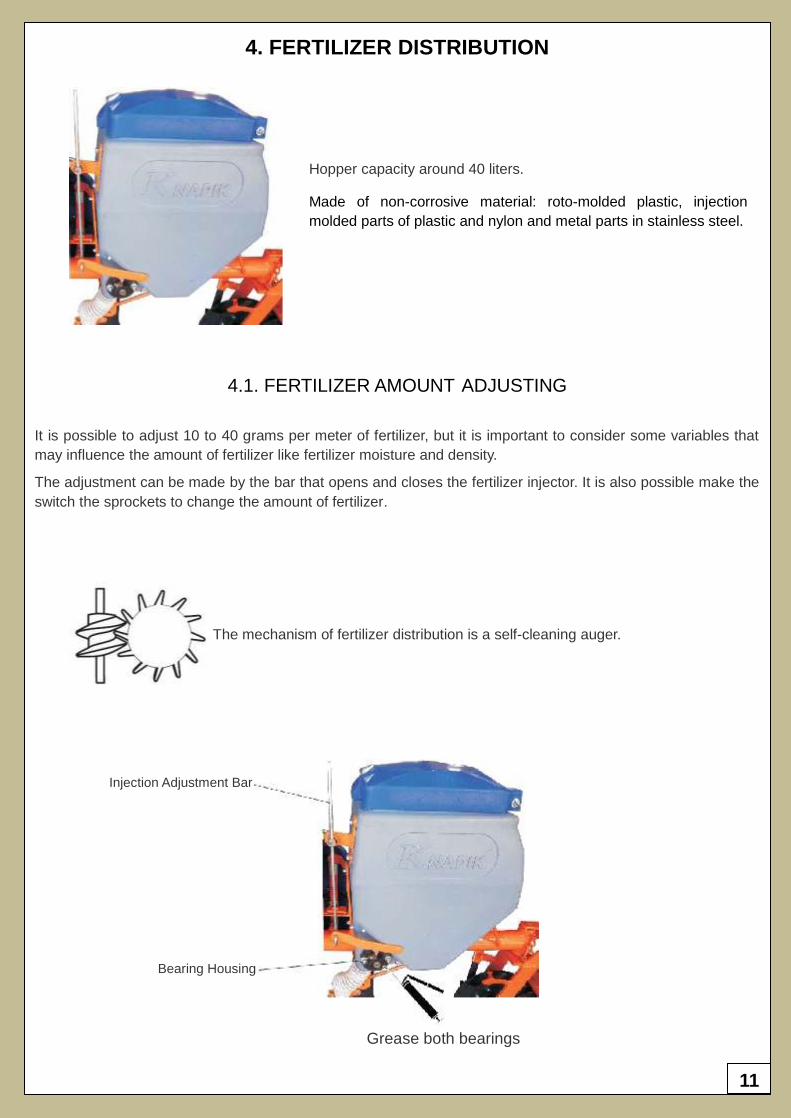
4. FERTILIZER DISTRIBUTION
Hopper capacity around 40 liters.
Made of non-corrosive material: roto-molded plastic, injection
molded parts of plastic and nylon and metal parts in stainless steel.
4.1. FERTILIZER AMOUNT ADJUSTING
It is possible to adjust 10 to 40 grams per meter of fertilizer, but it is important to consider some variables that
may influence the amount of fertilizer like fertilizer moisture and density.
The adjustment can be made by the bar that opens and closes the fertilizer injector. It is also possible make the
switch the sprockets to change the amount of fertilizer.
The mechanism of fertilizer distribution is a self-cleaning auger.
Injection Adjustment Bar
Bearing Housing
Grease both bearings
12
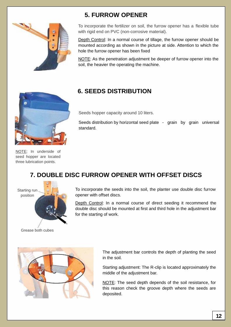
5. FURROW OPENER
To incorporate the fertilizer on soil, the furrow opener has a flexible tube
with rigid end on PVC (non-corrosive material).
Depth Control: In a normal course of tillage, the furrow opener should be
mounted according as shown in the picture at side. Attention to which the
hole the furrow opener has been fixed
NOTE: As the penetration adjustment be deeper of furrow opener into the
soil, the heavier the operating the machine.
6. SEEDS DISTRIBUTION
Seeds hopper capacity around 10 liters.
Seeds distribution by horizontal seed plate - grain by grain universal
standard.
NOTE: In underside of
seed hopper are located
three lubrication points.
7. DOUBLE DISC FURROW OPENER WITH OFFSET DISCS
To incorporate the seeds into the soil, the planter use double disc furrow
opener with offset discs.
Depth Control: In a normal course of direct seeding it recommend the
double disc should be mounted at first and third hole in the adjustment bar
for the starting of work.
Starting run
position
Grease both cubes
The adjustment bar controls the depth of planting the seed
in the soil.
Starting adjustment: The R-clip is located approximately the
middle of the adjustment bar.
NOTE: The seed depth depends of the soil resistance, for
this reason check the groove depth where the seeds are
deposited.
13
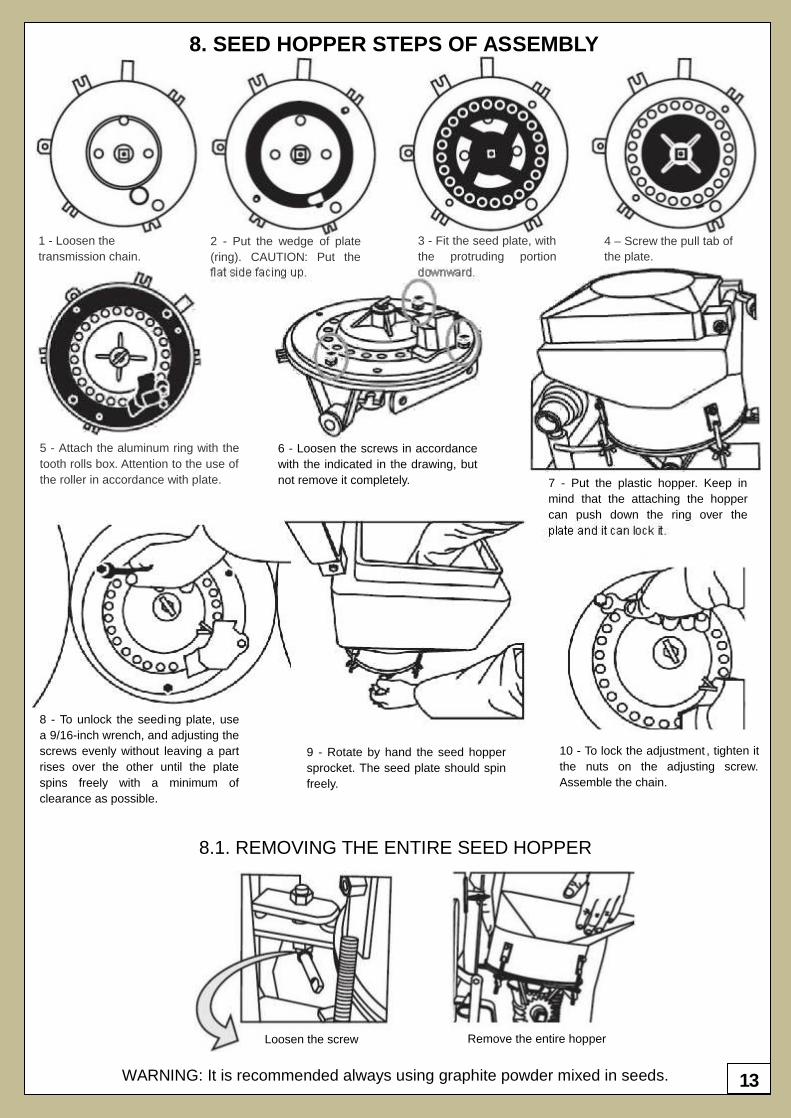
1 - Loosen the
transmission chain.
2 - Put the wedge of plate
(ring). CAUTION: Put the
flat side facing up.
3 - Fit the seed plate, with
the protruding portion
downward.
4 – Screw the pull tab of
the plate.
5 - Attach the aluminum ring with the
tooth rolls box. Attention to the use of
the roller in accordance with plate.
6 - Loosen the screws in accordance
with the indicated in the drawing, but
not remove it completely. 7 - Put the plastic hopper. Keep in
mind that the attaching the hopper
can push down the ring over the
plate and it can lock it.
8 - To unlock the seeding plate, use
a 9/16-inch wrench, and adjusting the
screws evenly without leaving a part
rises over the other until the plate
spins freely with a minimum of
clearance as possible.
9 - Rotate by hand the seed hopper
sprocket. The seed plate should spin
freely.
10 - To lock the adjustment , tighten it
the nuts on the adjusting screw.
Assemble the chain.
8.1. REMOVING THE ENTIRE SEED HOPPER
Loosen the screw Remove the entire hopper
WARNING: It is recommended always using graphite powder mixed in seeds.
8. SEED HOPPER STEPS OF ASSEMBLY
14
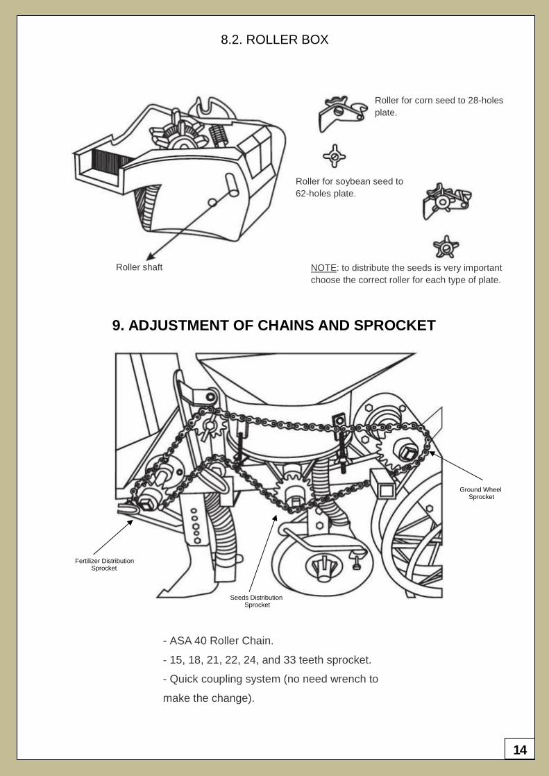
8.2. ROLLER BOX
Roller shaft
Roller for corn seed to 28-holes
plate.
Roller for soybean seed to
62-holes plate.
NOTE: to distribute the seeds is very important
choose the correct roller for each type of plate.
9. ADJUSTMENT OF CHAINS AND SPROCKET
- ASA 40 Roller Chain.
- 15, 18, 21, 22, 24, and 33 teeth sprocket.
- Quick coupling system (no need wrench to
make the change).
Ground Wheel Sprocket
Seeds Distribution Sprocket
Fertilizer Distribution Sprocket
15
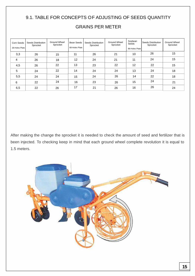
9.1. TABLE FOR CONCEPTS OF ADJUSTING OF SEEDS QUANTITY
GRAINS PER METER
After making the change the sprocket it is needed to check the amount of seed and fertilizer that is
been injected. To checking keep in mind that each ground wheel complete revolution it is equal to
1.5 meters.
3,3
264
4,5
5
5,5
6
6,5
26
26
24
24
22
22
15
18
22
22
24
24
26
11
12
13
14
15
16
17
26
24
23
24
24
23
21
21
21
22
24
26
26
26
10
11
12
13
14
15
16
26
24
22
24
22
24
26
15
15
15
18
18
21
24
Corn Seeds
28-Holes Plate
Bean Seeds
68-Holes Plate
Soybean Seeds
86-Holes Plate
Seeds Distribution Sprocket
Seeds Distribution Sprocket
Seeds Distribution Sprocket
Ground Wheel Sprocket
Ground Wheel Sprocket
Ground Wheel Sprocket
16
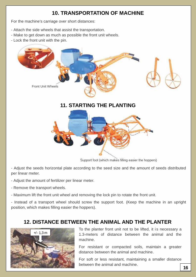
10. TRANSPORTATION OF MACHINE
For the machine's carriage over short distances:
- Attach the side wheels that assist the transportation.
- Make to get down as much as possible the front unit wheels.
- Lock the front unit with the pin.
Front Unit Wheels
11. STARTING THE PLANTING
Support foot (which makes filling easier the hoppers)
- Adjust the seeds horizontal plate according to the seed size and the amount of seeds distributed
per linear meter.
- Adjust the amount of fertilizer per linear meter.
- Remove the transport wheels.
- Maximum lift the front unit wheel and removing the lock pin to rotate the front unit.
- Instead of a transport wheel should screw the support foot. (Keep the machine in an upright
position, which makes filling easier the hoppers).
12. DISTANCE BETWEEN THE ANIMAL AND THE PLANTER
To the planter front unit not to be lifted, it i s necessary a
1.3-meters of distance between the animal and the
machine.
For resistant or compacted soils, maintain a greater
distance between the animal and machine.
For soft or less resistant, maintaining a smaller distance
between the animal and machine.
+/- 1,3 m
17
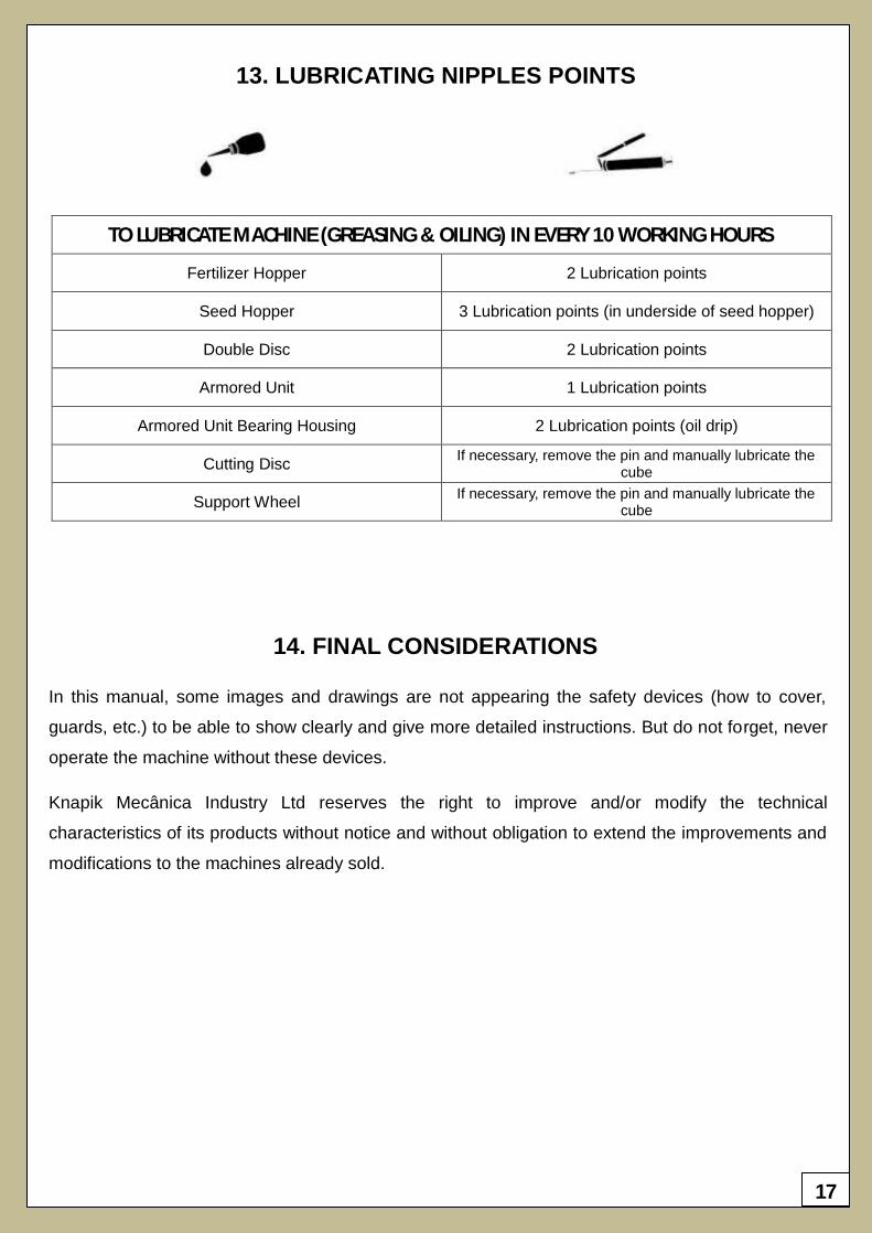
TO LUBRICATE MACHINE (GREASING & OILING) IN EVERY 10 WORKING HOURS
Fertilizer Hopper 2 Lubrication points
Seed Hopper 3 Lubrication points (in underside of seed hopper)
Double Disc 2 Lubrication points
Armored Unit 1 Lubrication points
Armored Unit Bearing Housing 2 Lubrication points (oil drip)
Cutting Disc If necessary, remove the pin and manually lubricate the
cube
Support Wheel If necessary, remove the pin and manually lubricate the
cube
13. LUBRICATING NIPPLES POINTS
14. FINAL CONSIDERATIONS
In this manual, some images and drawings are not appearing the safety devices (how to cover,
guards, etc.) to be able to show clearly and give more detailed instructions. But do not forget, never
operate the machine without these devices.
Knapik Mecânica Industry Ltd reserves the right to improve and/or modify the technical
characteristics of its products without notice and without obligation to extend the improvements and
modifications to the machines already sold.

18
Indústr
ia M
ecânic
a K
napik
Ltd
a
MARCH 2012 A empresa se reserva o direito de proceder alterações de seus produtos sem aviso prévio. La empresa se reserva el derecho de proceder alteraciones de sus productos sin aviso previo. The company reserves the right to modify products without prior notice.
INDÚSTRIA MECÂNICA KNAPIK LTDA
Rua Prefeito Alfredo Metzler, 480 - Bairro Santa Rosa
89400-000 Porto União – SC – Brasil
Tels: +55 (42) 3522-2789 | +55 (42) 3522-1819 | +55 (42) 3523-7926
Web: www.knapik.com.br
Email: [email protected]