Embed Size (px)
Citation preview

1PLX ConfidentialPLX Confidential
PLX Gen 2 Testing over “16 / 30” Tyco Comm Backplane
PLX Gen 2 Testing over “16 / 30” Tyco Comm Backplane
PLX Applications and MarketingPLX Applications and Marketing
2PLX ConfidentialPLX Confidential
IntroductionIntroduction
Introduction – PCIe of 30” Legacy BackplaneThis paper demonstrates the ability of PLX Gen2 switches to linkand operate with over 30 inches of a legacy Communication space (Tyco) backplane at both 2.5 and 5Gbps. In the communications space, the ability to drive distance and the ability to operate without a common clock reference are important factors for these systems. Both these conditions are set up and demonstrated. Link operation was established with approximately 40 total inches of PCB, multiple Hm-Zd and SMA connectors including approximately 2 feet of coax.
Introduction – PCIe of 30” Legacy BackplaneThis paper demonstrates the ability of PLX Gen2 switches to linkand operate with over 30 inches of a legacy Communication space (Tyco) backplane at both 2.5 and 5Gbps. In the communications space, the ability to drive distance and the ability to operate without a common clock reference are important factors for these systems. Both these conditions are set up and demonstrated. Link operation was established with approximately 40 total inches of PCB, multiple Hm-Zd and SMA connectors including approximately 2 feet of coax.
3PLX ConfidentialPLX Confidential
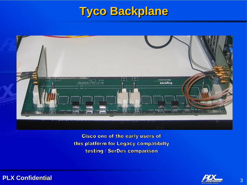
Tyco BackplaneTyco Backplane
4PLX ConfidentialPLX Confidential
Test ObjectiveTest Objective
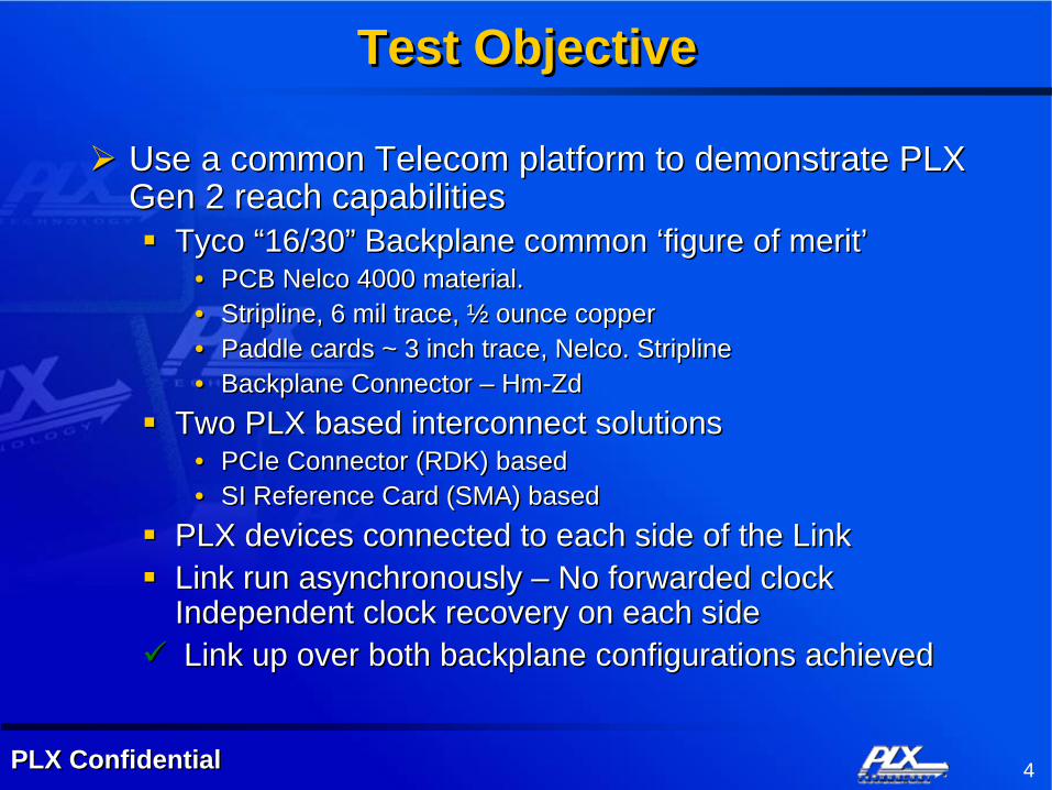
Use a common Telecom platform to demonstrate PLX Gen 2 reach capabilities
Tyco “16/30” Backplane common ‘figure of merit’• PCB Nelco 4000 material. • Stripline, 6 mil trace, ½ ounce copper• Paddle cards ~ 3 inch trace, Nelco. Stripline• Backplane Connector – Hm-Zd
Two PLX based interconnect solutions• PCIe Connector (RDK) based• SI Reference Card (SMA) based
PLX devices connected to each side of the LinkLink run asynchronously – No forwarded clock Independent clock recovery on each sideLink up over both backplane configurations achieved

5PLX ConfidentialPLX Confidential
PCIe Connector (RDK based)PCIe Connector (RDK based)
6PLX ConfidentialPLX Confidential
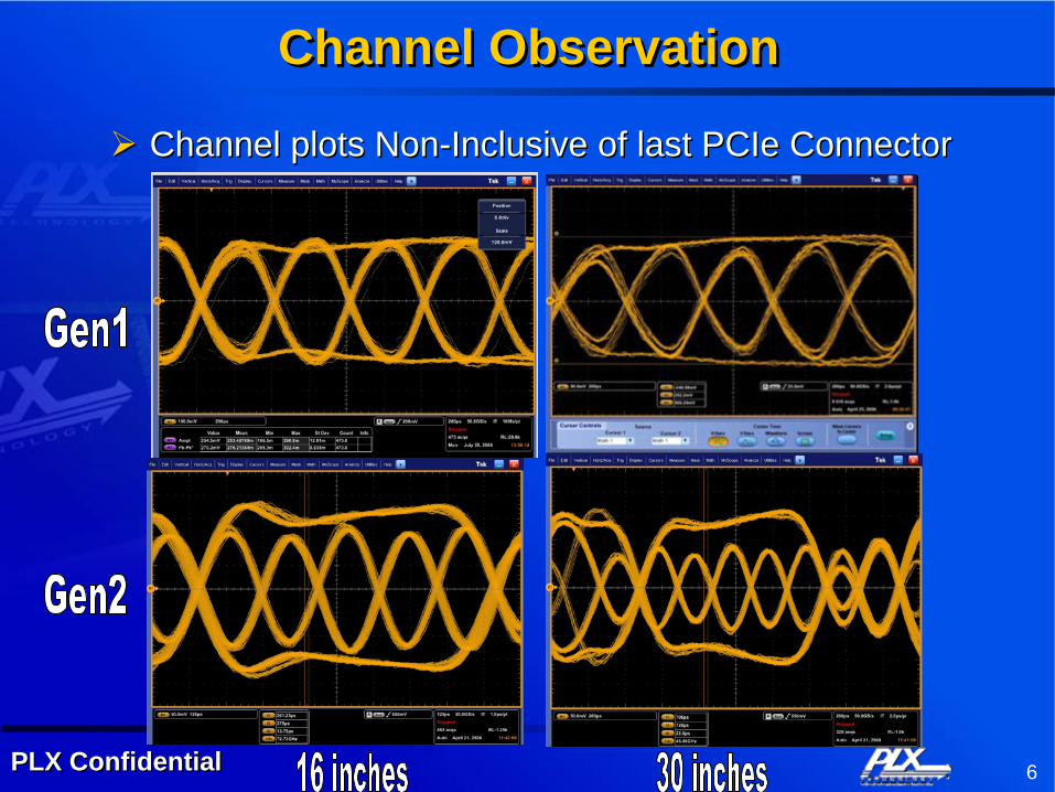
Channel ObservationChannel Observation
Channel plots Non-Inclusive of last PCIe ConnectorChannel plots Non-Inclusive of last PCIe Connector

7PLX ConfidentialPLX Confidential
PCIe Connector (RDK) based ResultsPCIe Connector (RDK) based Results
Gen 1 Linkup established at both “16 and 30”Default switch settings all that requiredTotal distance is ~ 41 inches of PCB + coaxMultiple transitions thru PCB,PCIE,SMA connectors
• Reflections, crosstalk, loss difficult to manageGen 2 Linkup established at “16 inches”
Tested overnight without bit errorTX swing slightly reduced. De-emphasis increased.
• ~600mV vs 650mV, ~10dB TX eq vs ~7.5dB RX EQ at defaultTotal effective link distance ~ 27 inches
• Channel Loss ~ 6dB• Estimated PCB BW on par with Signal BW

8PLX ConfidentialPLX Confidential
“16 / 30 Inch Testing Gen1”“16 / 30 Inch Testing Gen1”Gen1 Compliance PCIe ConnectorGen1 Compliance PCIe Connector

9PLX ConfidentialPLX Confidential
16 inch Losses16 inch Losses
From WhitepaperFrom Whitepaper

10PLX ConfidentialPLX Confidential
“16” inch Losses-Gen1“16” inch Losses-Gen1Excel ProgramExcel Program

11PLX ConfidentialPLX Confidential
“30” inch Losses-Gen1“30” inch Losses-Gen1
Excel ProgramExcel Program

12PLX ConfidentialPLX Confidential
SI Card based TestingSI Card based Testing

13PLX ConfidentialPLX Confidential
SI Card Based TestingSI Card Based Testing

14PLX ConfidentialPLX Confidential
SI CardSI Card

15PLX ConfidentialPLX Confidential
SI Card based TestingSI Card based Testing
Gen 2 Linkup established at both “16 and 30” inchesDefault switch settings fine for 16”
• ~ 25” of pcb plus coax“30” inch test used slightly reduced TX swing. De-emphasis increased. (600mv PLX drive / 10dB De-emphasis)
• Linearity more critical than loss with discontinuities• Multiple transitions thru PCB,PCIe,SMA Connectors• No PCIe Connector
Internal RX EQ kept at default• SI card accepts TFT EQ – not needed
Total effective link distance ~ 39 inches + coax• Channel Loss ~ 10 dB• Estimated PCB BW less than Signal BW ( ~1.6 Ghz)

16PLX ConfidentialPLX Confidential
Estimated Loss – Gen 2 “30”Estimated Loss – Gen 2 “30”

17PLX ConfidentialPLX Confidential
SI Card based TestingSI Card based Testing