Embed Size (px)
Citation preview
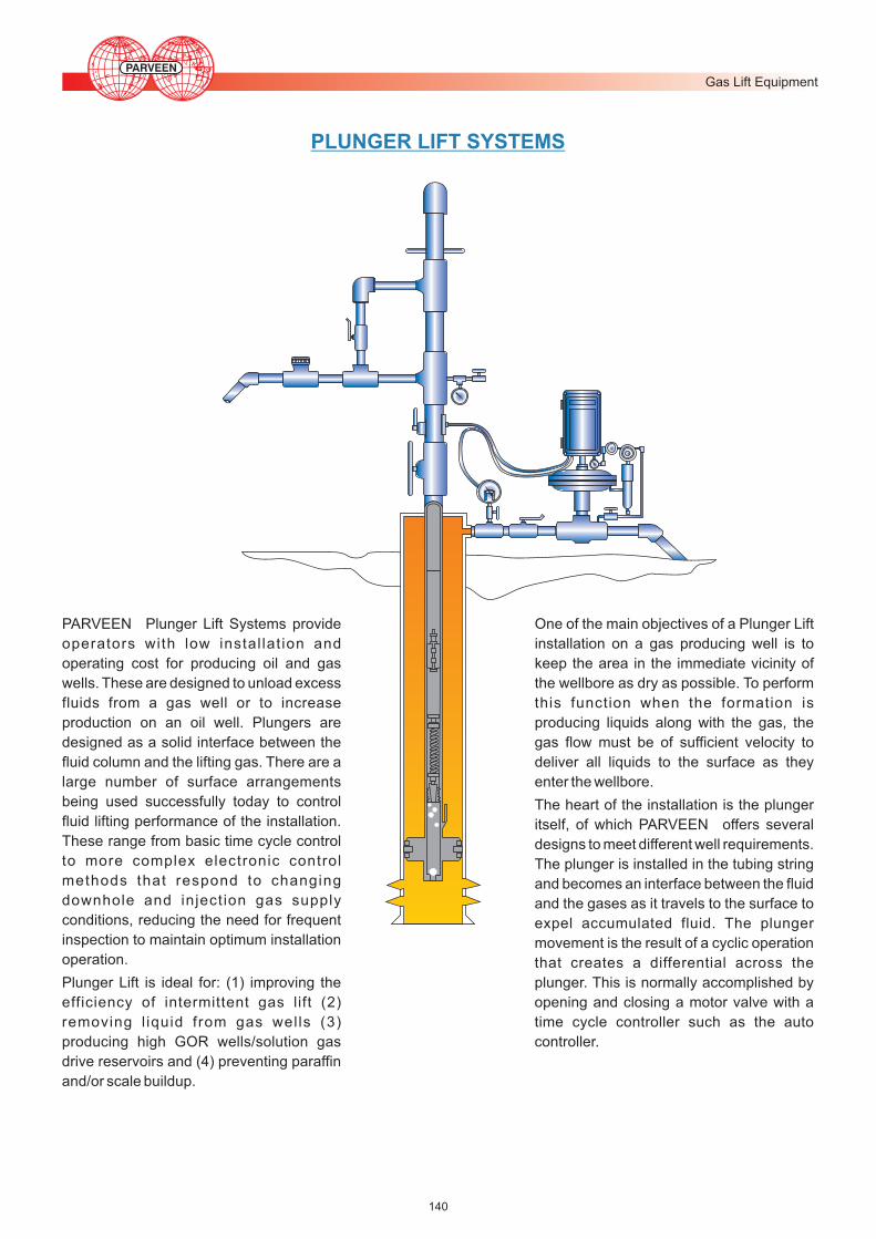
PLUNGER LIFT SYSTEMS
140
PARVEEN Plunger Lift Systems provide
operators with low instal lat ion and
operating cost for producing oil and gas
wells. These are designed to unload excess
fluids from a gas well or to increase
production on an oil well. Plungers are
designed as a solid interface between the
fluid column and the lifting gas. There are a
large number of surface arrangements
being used successfully today to control
fluid lifting performance of the installation.
These range from basic time cycle control
to more complex electronic control
methods that respond to changing
downhole and inject ion gas supply
conditions, reducing the need for frequent
inspection to maintain optimum installation
operation.
Plunger Lift is ideal for: (1) improving the
efficiency of intermittent gas lift (2)
removing l iquid from gas wells (3)
producing high GOR wells/solution gas
drive reservoirs and (4) preventing paraffin
and/or scale buildup.
One of the main objectives of a Plunger Lift
installation on a gas producing well is to
keep the area in the immediate vicinity of
the wellbore as dry as possible. To perform
this function when the formation is
producing liquids along with the gas, the
gas flow must be of sufficient velocity to
deliver all liquids to the surface as they
enter the wellbore.
The heart of the installation is the plunger
itself, of which PARVEEN offers several
designs to meet different well requirements.
The plunger is installed in the tubing string
and becomes an interface between the fluid
and the gases as it travels to the surface to
expel accumulated fluid. The plunger
movement is the result of a cyclic operation
that creates a differential across the
plunger. This is normally accomplished by
opening and closing a motor valve with a
time cycle controller such as the auto
controller.
Gas Lift Equipment
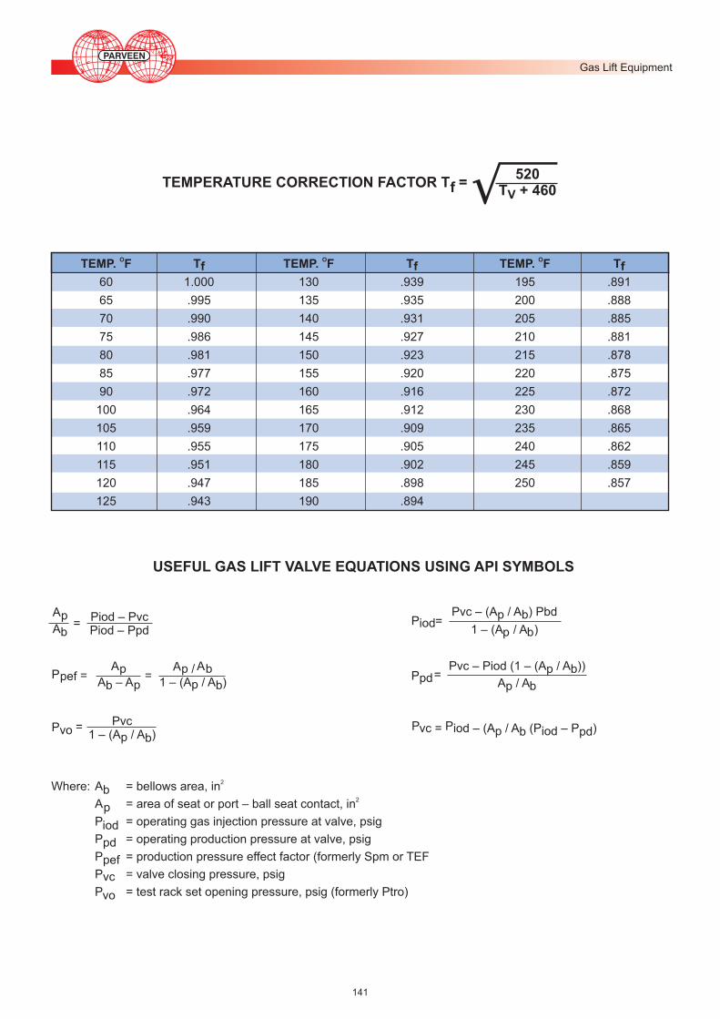
TEMPERATURE CORRECTION FACTOR T =f520
T + 460V
USEFUL GAS LIFT VALVE EQUATIONS USING API SYMBOLS
P Pvc = iod – (A / A (P – P )p iodb pd
ApAb
Piod – PvcPiod – Ppd
=
PpefAp
A – Apb
AAp / b1 – (A / A )p b
= =
PvoPvc
1 – (A / A )p b=
PiodPvc – (A / A ) Pbdp b
1 – (A / A )p b=
PpdPvc – Piod (1 – (A / A ))p b
A / Ap b=
2Where: A = bellows area, inb2 A = area of seat or port – ball seat contact, inp
P = operating gas injection pressure at valve, psigiod P = operating production pressure at valve, psigpd P = production pressure effect factor (formerly Spm or TEFpef P = valve closing pressure, psigvc P = test rack set opening pressure, psig (formerly Ptro)vo
O O O TEMP. F T TEMP. F T TEMP. F Tf f f
60 1.000 130 .939 195 .891
65 .995 135 .935 200 .888
70 .990 140 .931 205 .885
75 .986 145 .927 210 .881
80 .981 150 .923 215 .878
85 .977 155 .920 220 .875
90 .972 160 .916 225 .872
100 .964 165 .912 230 .868
105 .959 170 .909 235 .865
110 .955 175 .905 240 .862
115 .951 180 .902 245 .859
120 .947 185 .898 250 .857
125 .943 190 .894
141
Gas Lift Equipment