Embed Size (px)
Citation preview

wwwwww..iilliigghhtt--tteecchh..ccoomm
iLight Technologies • 118 South Clinton, Suite 370 • Chicago, IL 60661 • T 312.876.8630 • F 312.876.8631 • www.ilight-tech.com
CCoolloorr TTeemmppeerraattuurreess ((++//-- 1100%%))•• 2800K•• 3500K•• 4500K•• 6500K
DDiiffffuusseerr CCoolloorr (when not illuminated)•• Light amber hue
LLeennggtthhss AAvvaaiillaabbllee•• Standard lengths: 2’, 4’, 6’, 8’
(610 mm, 1219 mm, 1830 mm, 438 mm)•• Factory custom lengths available to the
nearest 1/2” (13mm) +/- 0.25’’ (6mm)1
•• 2’ (610mm) field cuttable pieces•• Illuminated outside corner pieces•• Factory convex or concave bends to minimum
inside radius of 5’’ (127mm)1
•• Factory “easy bends” to a 3/16” (5mm) radius1
•• Gentle field bends to a 48”(1219mm) radius2
PPlleexxiinneeoonn WWhhiittee 11XX SSeerriieess PPRROODDUUCCTT SSUUMMMMAARRYY
OORRDDEERRIINNGG IINNFFOORRMMAATTIIOONN
PPRROODDUUCCTT FFEEAATTUURREESS
•• Four Kelvin temperatures•• Energy efficient•• Long lifetime•• Stable and consistent color temperature•• Low voltage•• Easy to install•• Cool to the touch•• For use as exterior or interior accent
lighting, direct view or indirect view applications, coves & more
PPoowweerr SSuuppppllyy
•• Primary voltage: 120 or 120-277 depending on model•• Secondary voltage: 24VDC 4.1 A Max•• Maximum illumination length of a single 100W power supply
32 feet (9.75m)
PPoowweerr SSuuppppllyy TTiippss•• 20% maximum overage for breaker for primary current draw•• Do not plug multiple power supplies into one run of
Plexineon•• All iLight power supplies should be on an independent circuit•• Recommend surge protection upstream from power supply•• Verify correct voltage prior to wiring to non-switching
power supplies
LLooww VVoollttaaggee CCaabblleeMaximum distance of low voltage cable in any given run:•• 14 AWG: 40 feet (12.19m)•• 12 AWG: 60 feet (18.29m)•• 10 AWG: 100 feet (30.48m)
•• Class 2, 24 VDC, 100 Watts - must be supplied by iLight
3-2014-A
CLASS
T = Trim 24 = 24V S = Silver
VOLTAGE COLOR HOUSING CHANNEL VERSION
00 = With Connectors01 = Without Connectors
T 24 S
2F = 2 Feet4F = 4 Feet6F = 6 Feet8F = 8 FeetCL = Custom LengthPC = Outside CornerRT = 2 Foot Corner CuttableTT = 2 Foot Cuttable BE = Bend - Easy BN = Bend - ConvexBV = Bend - Concave
CC = Clear ChannelNC = No ChannelSC = Stainless Steel
Channel
WhiteW28 = 1X 2800KW35 = 1X 3500KW45 = 1X 4500KW65 = 1X 6500K
Specification sheets are subject to change without notice. For the most recent version,please refer to www.ilight-tech.com.
1. Drawing required for production2. Field bending allowed only on fixtures without C-channel
1
LENGTH
2
wwwwww..iilliigghhtt--tteecchh..ccoomm
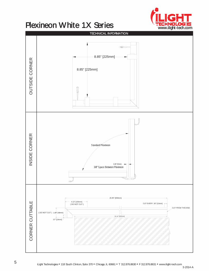
PPlleexxiinneeoonn WWhhiittee 11XX SSeerriieess TTEECCHHNNIICCAALL IINNFFOORRMMAATTIIOONN
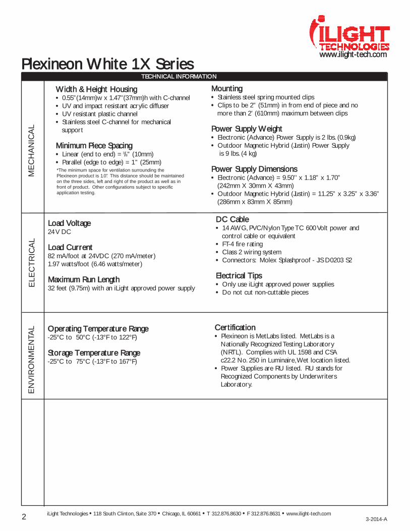
WWiiddtthh && HHeeiigghhtt HHoouussiinngg•• 0.55”(14mm)w x 1.47’’(37mm)h with C-channel•• UV and impact resistant acrylic diffuser•• UV resistant plastic channel•• Stainless steel C-channel for mechanical
support
MMiinniimmuumm PPiieeccee SSppaacciinngg•• Linear (end to end) = 3/8” (10mm)•• Parallel (edge to edge) = 1” (25mm)
MMoouunnttiinngg•• Stainless steel spring mounted clips•• Clips to be 2” (51mm) in from end of piece and no
more than 2’ (610mm) maximum between clips
PPoowweerr SSuuppppllyy WWeeiigghhtt•• Electronic (Advance) Power Supply is 2 lbs. (0.9kg)•• Outdoor Magnetic Hybrid (Justin) Power Supply
is 9 lbs. (4 kg)
PPoowweerr SSuuppppllyy DDiimmeennssiioonnss•• Electronic (Advance) = 9.50’’ x 1.18” x 1.70”
(242mm X 30mm X 43mm)•• Outdoor Magnetic Hybrid (Justin) = 11.25” x 3.25” x 3.36”
(286mm x 83mm X 85mm)
LLooaadd VVoollttaaggee24 V DC
LLooaadd CCuurrrreenntt82 mA/foot at 24VDC (270 mA/meter)1.97 watts/foot (6.46 watts/meter)
MMaaxxiimmuumm RRuunn LLeennggtthh32 feet (9.75m) with an iLight approved power supply
DDCC CCaabbllee•• 14 AWG, PVC/Nylon Type TC 600 Volt power and
control cable or equivalent •• FT-4 fire rating•• Class 2 wiring system•• Connectors: Molex Splashproof - JIS D0203 S2
EElleeccttrriiccaall TTiippss•• Only use iLight approved power supplies•• Do not cut non-cuttable pieces
ME
CH
AN
ICA
LE
LEC
TR
ICA
L
iLight Technologies • 118 South Clinton, Suite 370 • Chicago, IL 60661 • T 312.876.8630 • F 312.876.8631 • www.ilight-tech.com
EN
VIR
ON
ME
NTA
L OOppeerraattiinngg TTeemmppeerraattuurree RRaannggee -25°C to 50°C (-13°F to 122°F)
SSttoorraaggee TTeemmppeerraattuurree RRaannggee-25°C to 75°C (-13°F to 167°F)
CCeerrttiiffiiccaattiioonn•• Plexineon is MetLabs listed. MetLabs is a
Nationally Recognized Testing Laboratory(NRTL). Complies with UL 1598 and CSA c22.2 No. 250 in Luminaire,Wet location listed.
•• Power Supplies are RU listed. RU stands forRecognized Components by UnderwritersLaboratory.
3-2014-A
*The minimum space for ventilation surrounding thePlexineon product is 1.0”. This distance should be maintainedon the three sides, left and right of the product as well as infront of product. Other configurations subject to specificapplication testing.
3
wwwwww..iilliigghhtt--tteecchh..ccoommPPlleexxiinneeoonn WWhhiittee 11XX SSeerriieess
iLight Technologies • 118 South Clinton, Suite 370 • Chicago, IL 60661 • T 312.876.8630 • F 312.876.8631 • www.ilight-tech.com3-2014-A
TTEECCHHNNIICCAALL IINNFFOORRMMAATTIIOONN
PLE
XIN
EO
NP
RO
FIL
EP
LEX
INE
ON
CR
OS
S S
EC
TIO
NS
MO
UN
TIN
GC
LIP
S
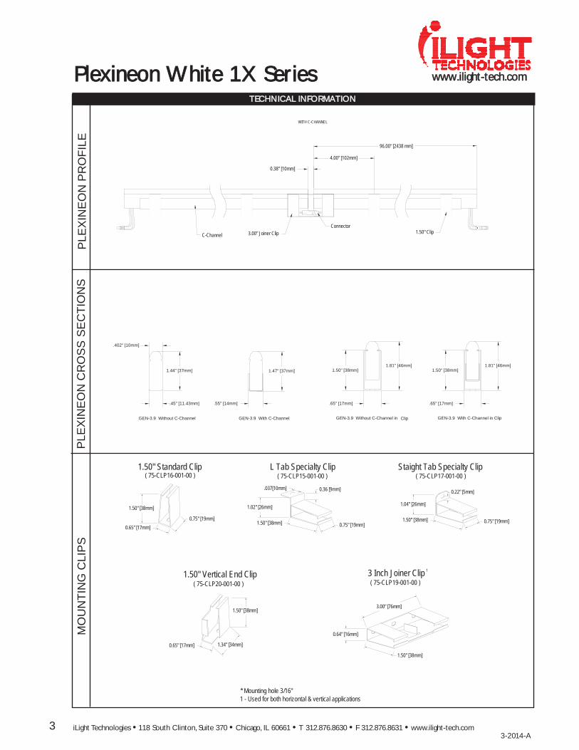
0.38" [10mm]
4.00" [102mm]
C-Channel 1.50" ClipConnector
WITH C-CHANNEL
3.00" Joiner Clip
96.00" [2438 mm]
1.44" [37mm]
.45" [11.43mm]
GEN-3.9 Without C-Channel
1.81" [46mm]
.65" [17mm]
1.50" [38mm]
GEN-3.9 With C-Channel
1.47" [37mm]
GEN-3.9 Without C-Channel in Clip
1.81" [46mm]
.65" [17mm]
1.50" [38mm]
GEN-3.9 With C-Channel in Clip
.55" [14mm]
.402" [10mm]
3.00" [76mm]
1.50" [38mm]
0.64" [16mm]
1.50" Standard Clip
0.65" [17mm]
1.50" [38mm]
1.34" [34mm]
1.50" Vertical End Clip
0.22" [5mm]
1.50" [38mm] 0.75" [19mm]
1.04" [26mm]
Staight Tab Specialty Clip
0.75" [19mm]1.50" [38mm]
1.02" [26mm]
L Tab Specialty Clip
3 Inch Joiner Clip
0.75" [19mm]0.65" [17mm]
1.50" [38mm]
( 75-CLP20-001-00 )
( 75-CLP15-001-00 ) ( 75-CLP17-001-00 )( 75-CLP16-001-00 )
( 75-CLP19-001-00 )
* Mounting hole 3/16"1 - Used for both horizontal & vertical applications
1
.037[10mm] 0.36 [9mm]
4
wwwwww..iilliigghhtt--tteecchh..ccoomm
iLight Technologies • 118 South Clinton, Suite 370 • Chicago, IL 60661 • T 312.876.8630 • F 312.876.8631 • www.ilight-tech.com3-2014-A
TTEECCHHNNIICCAALL IINNFFOORRMMAATTIIOONN
PLE
XIN
EO
NF
IELD
BE
ND
ING
1-3
PLE
XIN
EO
NFA
CTO
RY
BE
ND
ING
PPlleexxiinneeoonn WWhhiittee 11XX SSeerriieess
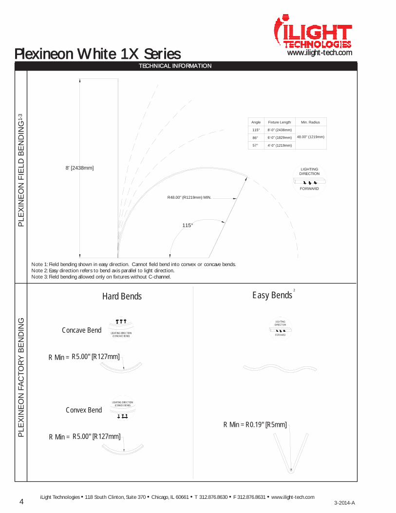
Note 1: Field bending shown in easy direction. Cannot field bend into convex or concave bends.Note 2: Easy direction refers to bend axis parallel to light direction.Note 3: Field bending allowed only on fixtures without C-channel.
8' [2438mm]
115°
R48.00" (R1219mm) MIN.
Angle Fixture Length Min. Radius
48.00" (1219mm)
115°
86°
57°
8'-0" (2438mm)
6'-0" (1829mm)
4'-0" (1219mm)
Easy Bends
R Min = R0.19" [R5mm]
Convex Bend
R5.00" [R127mm]R Min =
Concave Bend
R Min = R5.00" [R127mm]
Hard Bends2
LIGHTING DIRECTION(CONCAVE BEND)
LIGHTING DIRECTION(CONVEX BEND)
5
wwwwww..iilliigghhtt--tteecchh..ccoommPPlleexxiinneeoonn WWhhiittee 11XX SSeerriieess
iLight Technologies • 118 South Clinton, Suite 370 • Chicago, IL 60661 • T 312.876.8630 • F 312.876.8631 • www.ilight-tech.com3-2014-A
TTEECCHHNNIICCAALL IINNFFOORRMMAATTIIOONNO
UT
SID
E C
OR
NE
R
INS
IDE
CO
RN
ER
CO
RN
ER
CU
TTA
BLE
1
1
8.85" [225mm]
8.85" [225mm]
0.38" [10mm]
3/8" Space Between Plexineon
Standard Plexineon
1.89" [48mm]
CUT FROM THIS END
CUT EVERY4.13" [105mm]
25.95" [659mm]
.50" [13mm]
24.14" [813mm]
( DO NOT CUT )
( DO NOT CUT )
.57" [14mm]

6
wwwwww..iilliigghhtt--tteecchh..ccoomm
iLight Technologies • 118 South Clinton, Suite 370 • Chicago, IL 60661 • T 312.876.8630 • F 312.876.8631 • www.ilight-tech.com 3-2014-A
PPlleexxiinneeoonn WWhhiittee 11XX SSeerriieess TTEECCHHNNIICCAALL IINNFFOORRMMAATTIIOONN
PPlleexxiinneeoonn PPoowweerr SSuupppplliieess
ELE
CT
RO
NIC
(AD
VA
NC
E)
PO
WE
RS
UP
PLY
MA
GN
ET
ICH
YB
RID
( J
US
TIN
)P
OW
ER
SU
PP
LY I
N3R
EN
CLO
SU
RE
MA
GTE
CH
PO
WE
R S
UP
PLY
8.34" [212mm]
1.76" [45mm]
1.10" [28mm]9.50" [240mm]
65-ADV100W24VInput: 120-277VAC 50/60HzOutput: 24VDC 4AmaxRU Listed for U.S. and CanadaAdditional Enclosure RequiredSupplied by others2lbs. (0.9kg)
3.00" [76mm]
3.25" [83mm]
11.25" [286mm]
10.50" [267mm]
3.36" [85mm]
MANUAL RESET
COVER
65-PWR09-001-00Input: 120VAC 50/60HzOutput: 24VDC 4AmaxRU Listed for U.S.Enclosed in NEMA 3REnclosure 9lbs. (4kg)
12.34" [313mm]
0.74" [19mm]
11.34" [288mm]
2.41" [61mm]
65-24-96W-MAGInput: 100-277VAC 60HzOutput: 24VDC 4AmaxRU Listed for U.S.2lbs. (0.9kg)
.
__________
DAMP__________
WET
DRY
.
__________
DAMP__________
WET
DRY
.
__________
DAMP__________
WET
DRY


![Plexineon Color Series - iLight Technologies · Plexineon Color Series PRODUCT SUMMARY ... (NRTL). Complies with UL 1598 and CSA ... 65 17 1 50 38 hanne 1.47" [37mm] n lipanne 55](https://img.pdfslide.us/doc/110x75/5af86a257f8b9ae9489168fc/plexineon-color-series-ilight-technologies-color-series-product-summary-nrtl.jpg)


![37mm Load Data[1]](https://img.pdfslide.us/doc/110x75/547ee711b4af9fd3158b583f/37mm-load-data1.jpg)