Embed Size (px)
Citation preview

Please read this manual attentively before installation

© IS Technologies Co., Ltd. PAGE 2 / 126
Contents ABOUT THIS MANUAL ......................................................................................... 5
I. SAFETY GUIDE INSTRUCTION ......................................................................... 7
1. Authorized Personnel ................................................................................................................. 7
2. Operation ...................................................................................................................................... 7
3. Cautions ......................................................................................................................................... 7
4. Product Inspection ...................................................................................................................... 7
5. Symbols ......................................................................................................................................... 8
II. PRODUCT ......................................................................................................... 10
1. Principle of operation ...............................................................................................................11
2. Specification ...............................................................................................................................12
3. Product Package ........................................................................................................................14
4. Dimension ...................................................................................................................................16
III. INSTALLATION .............................................................................................. 19
1. General Guide ...........................................................................................................................19
2. Controller installation ...............................................................................................................20
3. Sensor Installation .....................................................................................................................22
IV. WIRING ........................................................................................................... 27
1. Wiring...........................................................................................................................................27
2. Sensor Cable ...............................................................................................................................32
V. OPERATION ..................................................................................................... 34
1. Start-up Display .........................................................................................................................34
2. Display .........................................................................................................................................35
3. Buttons .........................................................................................................................................40
VI. PROGRAMMING ........................................................................................... 43
1. LEVEL ............................................................................................................................................43

© IS Technologies Co., Ltd. PAGE 3 / 126
2. FOW ..............................................................................................................................................48
3. RELAY (RELAY1~3) .....................................................................................................................56
4. CURRENT OUTPUT ....................................................................................................................58
5. PULSE OUTPUT ...........................................................................................................................61
6. COMMUNICATION SETUP .......................................................................................................62
7. LOGGING SETUP ........................................................................................................................64
8. SYSTEM SETUP ...........................................................................................................................66
VII. MAINTENANCE ............................................................................................ 73
1. Battery .........................................................................................................................................73
2. SENSOR ........................................................................................................................................73
3. Firmware upgrading ..................................................................................................................74
4. Warranty Period .........................................................................................................................75
5. Repair Service .............................................................................................................................75
VIII. TROUBLE SHOOTING ................................................................................ 77
Error code list ..................................................................................................................................77
E1101 .................................................................................................................... 78
E2101 .................................................................................................................... 80
E0101 .................................................................................................................... 80
E1102 .................................................................................................................... 81
E2102 .................................................................................................................... 83
E0102 .................................................................................................................... 83
E0401 .................................................................................................................... 84
E0201 .................................................................................................................... 86
E0202 .................................................................................................................... 87
E0203 .................................................................................................................... 87

© IS Technologies Co., Ltd. PAGE 4 / 126
E1204 .................................................................................................................... 88
E2204 .................................................................................................................... 90
E0204 .................................................................................................................... 91
APENDIX A. SF-500S MENU LIST .................................................................... 93
APPENDIX B. RS-232/RS-485 PROTOCOL ..................................................... 99
APPENDIX C. VOLUME TABLE ........................................................................ 107

© IS Technologies Co., Ltd. PAGE 5 / 126
About this Manual This manual provides important information about the installation, wiring,
operation, and control of SF-500S and its sensors; LXD-04. Please read this
manual before installing or operating the product. In addition to operating
the product, this manual is very important. Please keep it in a safe place for
easy reference.
This manual is provided an electronic version only. The electric version is
provided with the product package or it can be downloaded through our
website (www.sondar.com).
Please note that the contents of this manual are subject to change without
prior notice if the product is modified, upgraded or improved.
Although we have checked all contents of this manual but there would be the
possibility to remain errors. Therefore the contents of this manual are
regularly updated. We welcome all suggestions for improvement.
SONDAR is a registered trademark of IS Technologies Co., Ltd.
Without our prior written permission, reproduction, distribution or any use
of manual contents are strictly prohibited.
Copyright IS Technologies Co., Ltd. 2013. All right reserved.

© IS Technologies Co., Ltd. PAGE 6 / 126
Safety Guide Instruction

© IS Technologies Co., Ltd. PAGE 7 / 126
I. Safety Guide Instruction 1. Authorized Personnel
The installation and operation of the product must be carried out by licensed
experts or qualified personnel. Please always wear protective equipment when
operating the products.
2. Operation Before operating the unit, please read this manual thoroughly. The
manufacturer isn’t responsible ’accidents caused by user s misuse or
’modification of the product without manufacture s permission. Conduct
periodic inspection of the product.
3. Cautions This manual provides all information you need to operate SF-500S, maintain
and trouble shoot. Please follow the instructions. The manufacturer is not
responsible in any way for the risk of an accident when user doesn’t follow
the instructions.
4. Product Inspection When opening the product package box, look carefully to determine if the
products or accessories have been damaged or contaminated. If the product
has been damaged, it may not function properly.

© IS Technologies Co., Ltd. PAGE 8 / 126
5. Symbols
Caution:
If it is ignored, faults or malfunctions could be result.
Warning:
If it is ignored, injury to people and serious damage to
the instrument could be result.
Electric Shock
If it is ignored, the product could be damaged by
electric shock
Information:
It provides additional information.

© IS Technologies Co., Ltd. PAGE 9 / 126
Product Description SF-500S | LXD-04

© IS Technologies Co., Ltd. PAGE 10 / 126
II. PRODUCT SF-500S is an ultrasonic non-contacting flow meter for open channels. The
measured level value is converted into the rate of flow in specific weirs or
flumes therefore the accurate level value is very important. LXD-04 is an
exclusive sensor for open channel flow, it provides accurate level reading.
SF-500S provides a variety of weirs and flumes formulations so it can be used
in different applications. The measured flow information is saved in the
memory of SF-500S and it can be downloaded by USB or transmitted by the
digital communication such as RS232, RS485 or Modbus.
Application:
LXD-Series sensors are suitable for liquids level monitoring in all industries,
particularly in the water and wastewater industry.
Weirs & Flumes
Parshall Flume
Suppressed Rectangular Weir
Contracted Rectangular Weir
V- [ ]Notch Triangular Weir
Cipolletti Weir
Leopold Lagco Flume
Palmer Bowlus Flume
H Flume
Trapezoidal Flume
• Compatible sensors only LXD-04. • XDS-300 sensor is not compatible with the SF-500S controller.
• Depending on the sensor material, the application can be restricted. Before installing the sensor, please check the chemical compatibility chart.

© IS Technologies Co., Ltd. PAGE 11 / 126
1. Principle of operation LXD-Series, the sensor transmits ultrasonic pulses to the measurement target.
The pulses are reflected from the surface of the target and received back by
the sensor. The running time is converted into the distance and it is
converted the level. The measured level is also converted into flow rate
according to the selected primary measurement device of SF-500S.
=D (C•T)/2
D: DISTANCE
C: SOUND VELOCITY
T: TIME OF FLIGHT
• Distance: from the sensor bottom to surface of the target
• Level: from the bottom of storage to surface of the target
• Empty: from the sensor bottom to the bottom of storage

© IS Technologies Co., Ltd. PAGE 12 / 126
2. Specification
SF-500S (Controller)
Measurement Method Ultrasonic non-contacting
Measurement Range 0.00m3 ~/h 200,000.00m3 /h
Accuracy %0.2 of F.S
Resolution 1mm
Damping Rate 0.1m/min - 100m/min adjustable
Data Logging Period Maximum 672 days (1hr interval)
Output Analog Two Analog 4~20mA, Ωmax 750 isolated
3 Relays
Digital RS232, RS485, Modbus
Display Illuminated Graphic LCD
IP Rating IP65
Temperature -20~60(-4~140) %, 80 relative humidity
Material Polycarbonate
Dimension ×166(W) 250(H)x95(D) mm
Weight ca. 2kg
Power Supply • 100~ ± %230V AC 15 , 50/60Hz, 29VA(12W)
Fuse: 250V T1.0A
• ~ DC 9 30V, Max 8W
LXD-04 (Sensor)
Range 0.3~4m (0.98- 13ft)
Bean Angle 8˚at -3dB
Process Connection 1” PF
Weight ca. 1.0kg
Material PVDF
Temperature -30~70 (-22~158) %, 80 relative humidity
Temperature Compensation by a built-in temperature sensor
IP Rating IP68
Cable 2 Core Shield (AWG18)
Cable Extension up to 450m (1,476.3ft)

© IS Technologies Co., Ltd. PAGE 13 / 126
External Temperature Sensor
Type NTC, 10 Ωk
Temperature -30~ 70 (-22~ 158)
Process Connection 1/8” PT
IP Rating IP68
Cable RG174
* The Specification is subject to change without prior notice.

© IS Technologies Co., Ltd. PAGE 14 / 126
3. Product Package SF-500S is a controller is operated with the sensor, LXD-04. SF-500S and
sensors are packed respectively.
3.1 Controller Box Package
Controller
(PG13.5 1EA)
(PG11.0 2EA)
Manual CD Cable Grand X3 Test Report
USB Connector Cable
External Temperature Sensor (Option)
• The protection grade of SF-500S is IP65. It is valid before the cable grand whole is made. When the product is delivered to the customers, the cable grand wholes are made for user’s convenience.

© IS Technologies Co., Ltd. PAGE 15 / 126
3.2 Sensor Box Package
1” Adapter
(option)
Test Report
Sensor Flange(option) Junction Box
(option)
Pipe (option)
• The basic length of the sensor is 1 meter. The cable length is subject to change as an option if requested when ordering.

© IS Technologies Co., Ltd. PAGE 16 / 126
4. Dimension
4.1 Controller 1) The enclosure material is polycarbonate and the protection grade is IP65.
2) Using the whole in the back of the controller it is mounted on the wall.

© IS Technologies Co., Ltd. PAGE 17 / 126
4.2 Sensor LXD-04 Sensor is an exclusive level sensor for SF-500S.its range is 4meter
(13ft). The temperature is compensated by a built-in temperature sensor. The
sensor materials are PP or PVDF. According to the application, the sensor
housing material must be selected. Before mounting the sensor, check the
chemical compatibility chart.
LXD-04
106.5 90.5
87.4 67

© IS Technologies Co., Ltd. PAGE 18 / 126
INSTALLATION

© IS Technologies Co., Ltd. PAGE 19 / 126
III. Installation 1. General Guide
Before mounting the product, read this manual and specification. It is
installed in a place that is within the temperature range specified in this
manual and that is suitable to the enclosure rating and materials. If the
products are installed improperly, it may cause malfunction.
This is general guide for installing SONDAR products.
Remove the obstacles in the space between the sensor and the measured target
such as ladders, limit switches, heating spirals etc.
When mounting the sensor, keep the distance to the vessel wall.
The bottom of the sensor should be perpendicular to the surface of water.
Do not set the maximum level into the Dead Zone range.
Avoid the intense winds and excessive exposure to direct sunlight. The strong
winds change the path of ultrasound and may cause a malfunction. If you need
to install the unit in a spot exposed to direct sunlight, sun screen must be
installed.
Keep the distance from the place where are strong noise by high voltage, high
current etc.
Install the unit in the place vibration free.

© IS Technologies Co., Ltd. PAGE 20 / 126
2. Controller installation
2.1 Environment condition In a place where ambient temperature is between - +20 to 60 ° C (-4~ 140)
In a place required minimum cable length.
In a place where it can be operated conveniently
In a place out of direct sunlight
In a place free from vibration
In a place that has sufficient space when its door is opened.
• Do not install near high voltage, current runs or variable frequency motors.

© IS Technologies Co., Ltd. PAGE 21 / 126
2.2 Installation Open the controller door and check the four screw holes.
Mark and drill four holes in the mounting wall.
Fasten the screw bolt by a screwdriver and mount the controller.
Check the controller leveled off on the wall.
Close the controller door.

© IS Technologies Co., Ltd. PAGE 22 / 126
3. Sensor Installation
3.1 Environment condition In a place where ambient temperature is between - +30 to 70 ° C (-22~ 94)
Suitable to the housing rating and materials for applications.
In a place where is perpendicular to the measuring target surface
3.2 Dead Zone ’Dead zone is the area which the ultrasonic sensor can t measure. The
maximum level shou ’ldn t be reached into the Dead Zone. The echo signal
’isn t calculated within Dead zone area. Thus the measurement value may not
correct.
Sensor Model Dead zone
LXD-04 0.3 m (11.81in)
• The sensor cable should not be laid parallel to high voltage line and nearby frequency converters.

© IS Technologies Co., Ltd. PAGE 23 / 126
3.3 Beam Space Make sure there is no interference on the emitted beam space area such as a
limit switch, temperature sensors, and ladders. .
Measurement
distance Beam Space(α)
1m 0.09m 2m 0.18m 3m 0.27m 4m 0.36m 5m 0.47m

© IS Technologies Co., Ltd. PAGE 24 / 126
3.4 Installation
3.4.1 Parshall Flume
The sensor must be installed at 2/3 the length (L) of the converging section
upstream of the beginning of the throat section.
3.4.2 Weir In the rectangular, triangular, and Cipolletti channels, the sensor should be
~installed at the top of the channel (Max. height x 4 5 times recommended).
L
2/3 L
L

© IS Technologies Co., Ltd. PAGE 25 / 126
3.4.2 Leopold Lagco Flume In the Leopold-Largco Flume, the sensor should be installed at a position
distant from Converging Section (corresponding to the distance of
measurement point according to Flumes size)
• The sensor must be installed above maximum level including the dead zone.
Flume Size Measurement Point
mm inches mm inches 100 ~ 4~12 25 1.0 380 15 32 1.3 455 18 38 1.5 530 21 44 1.8 610 24 51 2.1 760 30 64 2.5
Measurement Point [mm]
Converging

© IS Technologies Co., Ltd. PAGE 26 / 126
Wiring

© IS Technologies Co., Ltd. PAGE 27 / 126
IV. Wiring 1. Wiring
CONTROL TERMINAL BOARD There are 39 terminal blocks inside SF-500S. Make sure that all related
equipment is connected with each correct terminal block.

© IS Technologies Co., Ltd. PAGE 28 / 126
TRASDUCER
Sensor Channel 1 is selected when ordering SF-
500S, SENSOR2 Terminal block is eliminated.
• Do not use coaxial cable.
• Do not use connect the shield and white transducer wires together
• Do not use old version sensors. Connect only the sensors stated
in this manual.

© IS Technologies Co., Ltd. PAGE 29 / 126
Power The standard power type is AC power. DC power can be selected as an option if
requested when ordering. The thickness of the power cable should be more
than 0.755SQmm.
AC Power Terminal DC Power Terminal
• When turning on the power of SF-500S for the first time, make sure any connected devices are disabled until all system functions are confirmed and to be operating properly.
• The system must be protected by a 10A fuse, otherwise it should be installed in a place where there is a circuit breaker or switch in the building. The switch must be easily accessible.

© IS Technologies Co., Ltd. PAGE 30 / 126
Relay The Relay form is two Form C type. The relays can be wired either normally
open or normally closed. The standard model has 3 relays.
Two Form C, NO or NC relays
4A at 250Vac
Temperature Sensor The temperature information is a critical factor for measurement. LXD-05
sensor has built-in temperature sensor inside the sensor to compensate. If
the ambient temperature is changed rapidly, an external temperature sensor
is recommendable. The external temperature sensor for SF-500S can be
purchased if requested when ordering.

© IS Technologies Co., Ltd. PAGE 31 / 126
Analog output mA OUTPUT1 is the analog output for SENSOR1. mA OUTPUT2 is the analog
output for SENSOR2. Make sure that each output is wired to the correct
terminal block.
Digital Communication The standard communication type is RS232. RS485, Modbus can be selected as
an option if requested when ordering.

© IS Technologies Co., Ltd. PAGE 32 / 126
2. Sensor Cable LXD transducer cable is a shielded two-wire cable. The standard cable length
is 1meter (3.28ft). The cable can be extended by an option when placing the
order. When the cable needs to extend with other cable, the cable has to be a
shielded two-wire cable, same type.
Recommend to use a grounded conduit and a junction box for cable protection.
If the standard model is ordered, the
end of cable is provided as the picture
above.
If the cable is ordered more than 1meter,
the end of cable is provided as the picture
above.
• Do not use a coaxial cable for extension with SF-500S. The extension cable must be used same specification as LXD Series sensor cable

© IS Technologies Co., Ltd. PAGE 33 / 126
Operation

© IS Technologies Co., Ltd. PAGE 34 / 126
V. Operation 1. Start-up Display
When SF-500S is powered on, the screen shows as bellow picture.
Item
Model Name
Firmware Version

© IS Technologies Co., Ltd. PAGE 35 / 126
2. Display
2.1 Measuring Mode There are 4 different display types in Measuring mode. Switch through
different display by using up and down buttons. When only SENSOR1 is
wired, DISPLAY B and DISPLAY C aren’t shown.
DISPLAY A
3) It shows the current flow measurement value
4) It shows the relay currently wired.
5) It shows total flow.
6) It shows current level measurement value.
7) It shows a sensor condition.
• DT: when it operates normally • D: when it receive the reflected signal • S1: when the measurement value is over than DAMPING SPEED
(The value is held) • S2: when it research the signal • LE: when it lost the signal
8) It shows a system status.
• SYSTEM OK : normal status • SYSTEM OPEN: when the sensor is not wired or some cables are cut. • FAIL: when it can’t measure.

© IS Technologies Co., Ltd. PAGE 36 / 126
DISPALY B All the factors displayed are the same as those shown DISPLAY A. DISPLAY
B shows two sensors measurement at the same time. When only SENSOR1 is
wired, DISPLAY B isn’t shown.
1) It shows today’s date and current time
2) It shows instant flow value.
3) It shows total flow.
4) It shows the total hours measured
5) It shows total flow in a day.
6) It shows highest flow in a day
7) It shows level value currently being measured.
8) It shows lowest flow in a day
9) It shows the ambient temperature currently being measured.
10) It shows the flow graph.

© IS Technologies Co., Ltd. PAGE 37 / 126
Echo Trend DISPLAY
1) It shows the echo waveform received by sensor.
2) It shows the damping rate. The Setting Level is as below.
• SLOW • NORMAL • FAST • VERY FAST
3) It shows the measurement value currently measured.
4) It shows the sensor condition.
• DT: when it operates normally • D: when it receive the reflected signal • S1: when the measurement value is over than DAMPING SPEED (The value is held) • S2: when it research the signal • LE: when it lost the signal
5) It shows the threshold guide line.

© IS Technologies Co., Ltd. PAGE 38 / 126
2.2 Programming Mode Programming Mode is to be set the menus for measurement. Programming
Mode can be switche [ ]d by MENU button in measuring mode. It shows as the
picture as below.
LEVEL This menu is for detail parameter setup of level measurement.
FLOW This menu is for detail parameter setup of flow measurement.
RELAY This menu is for detail parameter setup of relay activity.
CURRENT OUTPUT This menu is for detail parameter setup of current output.
PULSE OUTPUT This menu is for detail parameter setup of pulse output.
COMMUNICATION SETUP This menu is for detail parameter setup of communication.

© IS Technologies Co., Ltd. PAGE 39 / 126
LOGGING SETUP This menu is for logging data management.
SYSTEM SETUP This menu is for system setting
NAVIGATION This menu allows for quick access to specific menus directly by entering the
preset menu number. Refer to the menu list of SF-500S.
* The menu list is page95.

© IS Technologies Co., Ltd. PAGE 40 / 126
3. Buttons SF-500S has 6 buttons to operate the system and to setup the menus.
• Measuring mode and Programming Mode is switched
by [MENU] button.
• Select a menu in Programming Mode.
• Complete menu setting
• Move up menus or change the parameters on
each menu.
• Move down menus or change the parameters
on each menu.

© IS Technologies Co., Ltd. PAGE 41 / 126
• Return to the previous category
• Move the cursor to the left when entering numbers.
• Return to the next category
• Move the cursor to the right when entering numbers.
• If you press [ENTER] button, after changing the value in Program Mode, every time the user is asked whether the changed value is saved or not. If you select [YES] then the value is changed and Measuring Mode is switched. When you want to change several menus in same directory, press [ENTER] button after all parameters are changed.

© IS Technologies Co., Ltd. PAGE 42 / 126
Programming

© IS Technologies Co., Ltd. PAGE 43 / 126
VI. Programming 1. LEVEL
QUICK SETUP is the menus frequently used. Parameters can be set
conveniently in short time.
1) UNIT
This menu is to select the unit of the value being measured.
- Unit Selection: mm, cm, m, in, yd, ft
Units mm 10000 cm 1000 m 10 in 393.70 yd 10.94 Ft 32.81
**Round off the numbers to two decimal places

© IS Technologies Co., Ltd. PAGE 44 / 126
2) TEMP UNIT
This menu is to select the unit of ambient temperature being measured.
- Measuring range: mm, cm, m, in, yd, ft
3) EMPTY
This menu is for setting the distance between the bottom of the sensor and
the bottom of the measured storage when there is empty. The input unit is
changed depending on the measurements unit.
Sensor setting range Default LXD-04 0. 30~4.50m 1.2m
• The setting value of EMPTY is mostly maximum measuring range of the sensor. However, the bottom distance could be set as 99.99m depending on the application conditions. The incorrect bottom distance value causes the incorrect measurement.
4) DEAD ZONE
This menu is for setting DEAD ZONE of a sensor. The ultrasonic sensor is both
transmission and reception sensor. The sensor is not able to measure the distance
between the surface of the sensor and the certain point. That distance is called
DEAD ZONE.
Sensor Setting range Default LXD-04 0. 25~4.50m 0.25m
5) TX POWER
This menu is for adjusting the strength of the transmission signal output
from the ultrasonic sensor. By using the function that adjusts the intensity of
the ultrasonic wave generated form the sensor, this product is applicable for
the various environments.
[ ~ ]Default setting: 30, Maximum setting range: 1 100

© IS Technologies Co., Ltd. PAGE 45 / 126
• 10: When ultrasonic output is weak. • 30: The general case (Standard mode) • 50: When ultrasonic output is strong. • 70: When ultrasonic output is very strong.
6) RX GAIN
This menu is for adjusting the sensitivity of the signal received from the
sensor. Attenuation of the ultrasonic signal is occurred depending on the
install location, environment, and surface of measurement object. Please to
correct this on the basis of the setting of the following criteria.
[ Default setting: 80 ~ ], Maximum setting range: 1 100
• 30 or less: The Amplification degree is weakest. When the amplification degree of the received signal is about 20dB. (Short-range measurement of enclosed space or underground water pipe.)
• 50: When the amplification degree of the received signal is about 25dB. (Short-range measurement of enclosed space or underground water pipe.)
• 80: The general case. When the amplification degree of the received signal is about 30dB. (Standard mode),
• 90: When the amplification degree of the received signal is about 40dB. (Long-range measurement in open space)
• 95: When amplification degree of the received signal is about 50dB. • (When the dust, powder, and solid there is a risk of diffuse reflection of the
ultrasonic wave.)
7) THRESHOLD
This is the menu for setting the reference value used to detect the received
signal reflected. To avoid false detection, please set THRESHOLD value high in
the noisy environment and please set THRESHOLD value low when
environmental noise is low.
• [Default setting: 4(0.8V), Maximum setting range: 1~10]

© IS Technologies Co., Ltd. PAGE 46 / 126
8) TEMP TYPE
This is the menu for selecting the type of the temperature value used in the
ultrasonic distance measurement.
• INSIDE: Use the temperature sensor that is built inside the sensor for ultrasonic measuring.
• OUTSIDE: Use the value of the external temperature sensor for ultrasonic measuring. (optional)
• FIX: Set a fixed value without using a temperature sensor when the device is used in the places where the temperature is changed rapidly.
•
• When using the external temperature sensor for measurement, TEMP TYPE should be selected as OUTSIDE always. If it is set as OUTSIDE, but the external temperature sensor is not actually connected, it might be displayed incorrect measurement value instead of the actual measurement value.
9) TEMP FIX
This menu is for setting the value of the temperature manually when TEMP
TYPE is FIX.
Sensor Celsius() Fahrenheit() Range 0~60 32~140
10) TEMP
This menu is for checking the temperature value measured currently.
11) DAMPING
This menu is for setting the speed of output change corresponding to the
change in water level.
Select Item Slow Normal Fast Very Fast Speed 0.1m/min 1m/min 10m/min 100m/min

© IS Technologies Co., Ltd. PAGE 47 / 126
12) SOUND SPEED
This menu is for setting the sound speed value of the environment used.
Please enter 331.5 in general. (in the air) If this product is operated in other
gases, please enter the sound speed value of the corresponding gas when the
temperature is 0 . (unit: m/sec)
13) SOUND SPEED FACTOR
This menu is for setting the sound speed change value due to temperature.
Sound speed is changed depending on the temperature. In the air, please enter
0.60 (m / ) in general. In the case of special circumstances, please enter the
sound speed change value obtained by experiment to obtain an accurate
measured value.
Name of gas Sound speed (m/sec) Chlorine 206
Carbon dioxide 259 Argon 308
Oxygen 316 Air 331.5
Ammonia 415 Ethane 430 Neon 435
Helium 965

© IS Technologies Co., Ltd. PAGE 48 / 126
2. FOW Set the detail menu for flow parameters.
1) FLOW UNIT
This menu is to select the unit of the flow value being measured.
- Unit selection: [ ] [ ] [ ]m3/h, m3/d, l/min, ft3/s, GPM UK , GPM US , MGD UK ,
[ ]MGD US
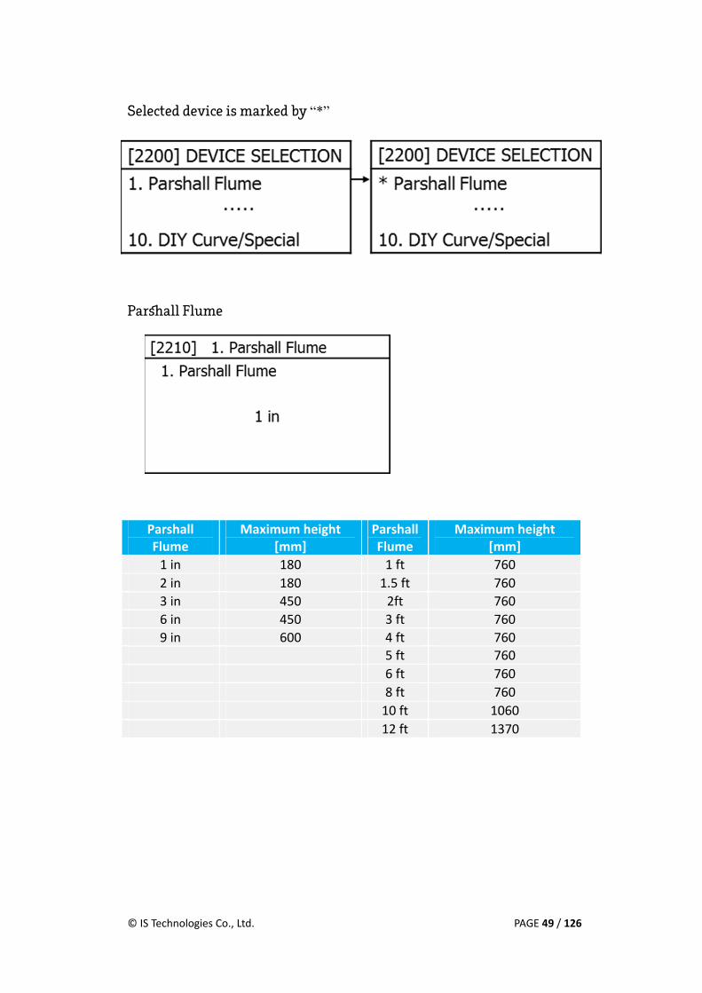
2) DEVICE SELECTION
This menu is for channel selection and
detailed parameter setting. Select the
channel first and then, set parameters for
the channel.
• When the weir or flume is selected, the current value and relay are changed according to the selected weir or flume.
© IS Technologies Co., Ltd. PAGE 49 / 126
Selected device is marked by “*”
Parshall Flume
Parshall Flume
Maximum height [mm]
Parshall Flume
Maximum height [mm]
1 in 180 1 ft 760 2 in 180 1.5 ft 760 3 in 450 2ft 760 6 in 450 3 ft 760 9 in 600 4 ft 760
5 ft 760 6 ft 760 8 ft 760 10 ft 1060 12 ft 1370

© IS Technologies Co., Ltd. PAGE 50 / 126
Rect.Suppressed
Rect. Suppressed
Maximum height[mm]
Rect. Suppressed
Maximum height [mm]
1 ft 150 4 ft 600 1.5 ft 220 5 ft 750 2 ft 300 6 ft 900
2.5 ft 370 8 ft 1200 3 ft 450 10 ft 1500
Rect. Contracted
Rect. Contracted
Maximum height[mm]
Rect. Contracted
Maximum height [mm]
1 ft 150 4 ft 600 1.5 ft 220 5 ft 750 2 ft 300 6 ft 900
2.5 ft 370 8 ft 1200 3 ft 450 10 ft 1500
If there is no channel that installed on the menu, please complete the
following steps. [ ]At 2293 Rectangular Weir menu, Please select Suppressed
Weir and enter the conrresponding Crest Length.

© IS Technologies Co., Ltd. PAGE 51 / 126
V-Notch Weir
[ Type: 22.5°/ 30°/ 45°/ 60°/ 90°/ 120°]
Cipoletti Weir
Cipoletti Weir
Maximum height[mm]
Cipoletti Weir
Maximum height [mm]
1 ft 150 4 ft 600 1.5 ft 220 5 ft 750 2 ft 300 6 ft 900
2.5 ft 370 8 ft 1200 3 ft 450 10 ft 1500

© IS Technologies Co., Ltd. PAGE 52 / 126
Leopold Lagco Flume
Leopold Lagco Flume
Maximum height [mm]
Leopold Lagco Flume
Maximum height [mm]
4" 70 15" 270 6" 100 18" 320 8" 130 21" 380
10" 180 24" 420 12" 210 30" 530
Palmer Bowlus Flume
Palmer Bowlus Flume
Maximum Hight [mm]
Palmer Bowlus Flume
Maximum Heght [mm]
4" 75 15" 270 6" 105 18" 320 8" 150 21" 380
10" 180 24" 420 12" 210 30" 485

© IS Technologies Co., Ltd. PAGE 53 / 126
H Flume
H Flume Maximum
Height [mm]
H FlumeMaximum
Height [mm]
0.5H 150 4.5 H 1370 0.75H 220 0.4 HS 120 1.0 H 300 0.6 HS 180 1.5 H 450 0.8 HS 240 2.0 H 610 1.0 HS 300 2.5 H 760 3.0 HS 910 3.0 H 910 4.0 HS 1220
TRAPEZOIDAL Flume
TRAPEZOIDAL Flume
Maximum height [mm]
TRAPEZOIDAL Flume
Maximum height [mm]
Sm. 60°V 90 2" 45° WSC 250
Lg. 60°V 150 12" 45° SRCRC 380
XL 60°V 285 2.0' SRCRC 860 3.0' 60°V 755

© IS Technologies Co., Ltd. PAGE 54 / 126
DIY Curve/Special
This menu is used for measurement of flow rate, regardless of the type of
device.
• DIY Curve: This option equally divides the known level-based flow rate into 10 parts and measures the flow rate according to change of level.
• Q=K*H(PWR): This option inputs constant values, K and PWR, to a exponentially changing device and measures the flow rate.
• Rectangular Weir: This option selects Crest Length of all Rectangular Weirs in mm unit and measures the flow rate.
3) LOW CUT VALUE
This is the menu to set minimum measurable flow rate. Those below this
" "value will be treated as 0 . The initial value is 0.00m3/h(0.00 gal/m).
~(Setting range: 0.00 Max. Flow Rate, Unit: 0.01m3/h(0.01 gal/m)).

© IS Technologies Co., Ltd. PAGE 55 / 126
4) HIGH CUT VALUE
This is the menu to set maximum measurable flow rate. Those above this
value will be treated as the maximum flow rate. The initial value is
maximum flow rate of the device (gal/m). ( ~Setting range: 0.00 Max. flow
rate)
5) TOTALIZER
This is a menu for setting the default value of TOTAL FLOW and TOTAL TIME.
6) FLOW RATE
This menu is to revise and output the flow rate that are measured in arbitrary
ratio by user. This menu also can be used for weight conversion, error
correction.
Display & Output = Measured value x FLOW RATE
(Setting range ~: 0.001 9.999)

© IS Technologies Co., Ltd. PAGE 56 / 126
7) FLOW INDEX
Highest or lowest flow rate based on the selected height of the channel can be
searched by m3/h or gal/h unit.
3. RELAY (RELAY1~3)
DETAIL
1) FUNCTION
This menu is for selecting RELAY use state.
• NONE: Not use this RELAY • LIMIT: Operate each RELAY depending on the value of the ON / OFF. • ALTERNATE: Operate RELAY in sequence on the basis of the measured value and
the ON / OFF POINT value of the group that has been set.

© IS Technologies Co., Ltd. PAGE 57 / 126
Ex) If There are RELAY1 and RELAY 2 at the GROUP1, RELAY 1 is working to the first ON / OFF point and then RELAY 2 is working at the second ON / OFF point.
• ALARM: This menu is for generating alarm signals when errors that caused by error on the Fail Safe Time value occurs consistently.
2) GROUP
This menu is for setting a group for ALTERNATE.
• Selection range: 1~3
ON POINT
This menu is for setting a point that RELAY is ON. If OFF POINT is less than
ON POINT, RELAY become ON when the measured value is bigger than ON
POINT. If OFF POINT is bigger than ON POINT, RELAY become ON when the
measured value is less than ON POINT.
OFF POINT
This menu is for setting a point that RELAY is OFF.
If OFF POINT is less than ON POINT, RELAY become OFF when the measured
value is less than OFF POINT. If OFF POINT is bigger than ON POINT, RELAY
become ON when the measured value is bigger than OFF POINT.

© IS Technologies Co., Ltd. PAGE 58 / 126
RELAY SIMULATION
The ON / OFF test of RELAY is available.
4. CURRENT OUTPUT This menu is for setting that is needed to convert the measured value to
current output.
1) INPUT TYPE
This menu is for selecting the measurement of Level or Flow.
2) 4mA POINT SET
This menu is to set 4mA.

© IS Technologies Co., Ltd. PAGE 59 / 126
3) 20mA POINT SET
This menu is to set 20mA.
4) FAIL SAFE CURRENT
This menu is for setting the operation of the current output when an error
occurs.
• 3.8Ma • HOLD • 22mA
5) CURRENT SIMULATION
This menu is that displays the
output of CURRENT OUTPUT
SENSOR1 and SENSOR2 as selected
value.
• 3.8mA • 4mA • 12mA • 20mA • 22mA

© IS Technologies Co., Ltd. PAGE 60 / 126
6) CURRENT SIMULATION
This function can simulate the cable connection status and the current output
between the central control room and this device. When you move to the
CURRENT SIMULATION menu, the measuring process is stopped and the
current output becomes initialized to 0.
OUTPUT 1
When you select a value of the Current Output 1and 2, it is output by the value of
the corresponding current.
• HOLD • 3.8mA • 4mA
• 12mA • 20mA • 22mA
OUTPUT 2
Same as the OUTPUT 1

© IS Technologies Co., Ltd. PAGE 61 / 126
5. PULSE OUTPUT
1) FUNCTION
It is the menu for selection of pulse output use.
• DISABLE: PULSE OUTPUT is not used. • ENABLE: PULSE OUTPUT is used.
2) PULSE WIDTH
This is a Menu to set the width of the pulse that one pulse is output
depending on the flow rate value that has been set at the PULSE VALUE..
(Default setting: 0.10sec, Setting range ~: 0.01 1.00, Unit: 0.01sec)
3) PULSE VALUE
This is a menu to set the flow rate value per pulse. If you enter 1.0, It mean
1 pulse is discharged 1.0.

© IS Technologies Co., Ltd. PAGE 62 / 126
6. COMMUNICATION SETUP
4) RS-232 SETUP
USE
This menu is for selecting the RS-232 use state.
• ENABLE / DISABLE
BAUDRATE
This menu is for selecting the transmission speed of RS-232.
• 4800 bps • 9600 bps • 14400 bps • 19200 bps • 38400 bps • 57600 bps • 115200 bps

© IS Technologies Co., Ltd. PAGE 63 / 126
PARITY
This menu is for selecting the Parity bit use state.
• None • Odd • Even
STOP BIT
This menu is for selecting the size of the STOP BIT of RS-232 data
transmission.
• 1 bit (default) • 2 bit
DATA BIT
This menu is for selecting the size of the transmission data of RS-232.
• 7 bit • 8 bit (default)
PROTOCOL
This menu is for selecting the protocol of the measurement data that is output
by RS-232.
• SONDAR • BKCM • Modbus – RTU • Modbus–ASCII
RS-485 SETUP

© IS Technologies Co., Ltd. PAGE 64 / 126
7. LOGGING SETUP This menu is for setting LOGGING PERIOD, LOGGING ERASE, USB LOGGING.
1) 3.1 LOGGING PERIOD
This menu is for setting the Logging period of measurement data.
Maximum storage period according to the data logging period (16,128 point)
• NONE • 10 SEC • 1 MINUTE • 5 MINUTE
• 10 MINUTE • 15 MINUTE • 30 MINUTE • 60 MINUTE
Data logging period Maximum storage period 10 SEC 2 days
1 MINUTE 11 days 5 MINUTE 56 days
10 MINUTE 112 days 15 MINUTE 168 days 30 MINUTE 336 days
60 MINUTE 672 days

© IS Technologies Co., Ltd. PAGE 65 / 126
3.2 LOGGING ERASE If you select LOOGING ERASE, Screen [will be displayed as shown in Figure 6-
]25 . By selecting OK, it initializes the saved logging.
3.3 USB LOGGING When USB is connected, screen will be di [splayed as shown in Figure 6- ]26 .
By selecting OK, it transfers logging data to USB as EXCEL file.
When USB is not connected, screen will be displayed as shown in the picture
below. Please connect USB, and then click the OK button, the error pop-up will
disappear.

© IS Technologies Co., Ltd. PAGE 66 / 126
8. SYSTEM SETUP
1) SYSTEM INFO
This menu is for showing system information.
• Version: Firmware version • SYSTEM ID: System ID for SONDAR protocol • UNIT: Measurement unit selected by a user

© IS Technologies Co., Ltd. PAGE 67 / 126
2) SYSTEM ID
1)
2)
3)
SYSTEM ID
This menu is for setting the SYSTEM ID to be used for SONDAR Protocol.
• Setting range: 0 ~ 99
Modbus ID
This menu is for setting the Slave ID required when using Modbus Protocol.
4) SYSTEM TIME
This menu is for setting the system time. By using the Left / Right direction
button, move the cursor to the year / month / day / hour / minute, change the
setting using the Up / Down direction button.
• Setting range: JAN/01/2000 00:00 ~ DEC/31/2099 23:59

© IS Technologies Co., Ltd. PAGE 68 / 126
5) PASSWORD
This menu is for setting a password by its user. No password is set at the
factory. After you set a password, you must enter the password each time
there is a menu change.
• Password setting range: 0000~9999
• User can’t configure the menus when user forgets the password. Please note password number and pay attention not to lose it.
© IS Technologies Co., Ltd. PAGE 69 / 126
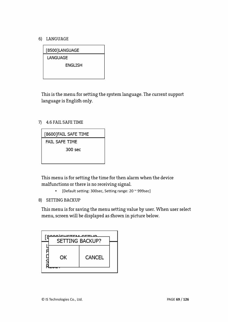
6) LANGUAGE
This is the menu for setting the system language. The current support
language is English only.
7) 4.6 FAIL SAFE TIME
This menu is for setting the time for then alarm when the device
malfunctions or there is no receiving signal.
• [Default setting: 300sec, Setting range: 20 ~ 999sec]
8) SETTING BACKUP
This menu is for saving the menu setting value by user. When user select
menu, screen will be displayed as shown in picture below.

© IS Technologies Co., Ltd. PAGE 70 / 126
9) RESET
MASTER RESET
This menu is for resetting the device that is currently operating. If you select
MASTER RESET function, the device will be initialized as default setting.
USER RESET
This menu is for resetting the device that is currently operating. If you select
USER RESET, the device will be initialized as menu value that is stored at
SETTING BACKUP.

© IS Technologies Co., Ltd. PAGE 71 / 126
9. NAVIGATION This menu allows for quick access to specific menus directly by entering the
preset menu number. Refer to the menu list of SF-500S.
Ex) [If you want to move to the menu of LOGGING PERIOD, please enter menu number 6100] .
[By entering menu number 6100] , you can access RS-232 SETUP menu immediately..

© IS Technologies Co., Ltd. PAGE 72 / 126
Maintenance

© IS Technologies Co., Ltd. PAGE 73 / 126
VII. Maintenance Regular Inspection
There are no contaminants on the surface of sensor.
Current output is working in the normal range of 4-20mA.
Value displayed at the screen is same as actual level value.
Rating power supply is approved.
1. Battery
The battery which is equipped on the main board of SF-500S is CR-2032 from
Maxwell Co. The normal product life is around 10 years but it is subject to
change by the environment and operating condition. The life can be
shortened. Before the battery is out, check it regularly and change it.
• If the battery is out, the time data cannot back-up.
• The battery brand and specification will be subject to change without prior notice.
2. SENSOR
1) Check the sensor cable regularly.
2) Check the sensor bottom if there is contaminant and clean the bottom of the sensor.

© IS Technologies Co., Ltd. PAGE 74 / 126
3. Firmware upgrading SL-100S provides the firmware upgrading by a user.
Duplicate the firmware to download at the highest folder of USD memory.
(file system: FAT32). Connect the USB memory to the Controller. Keep
pressing the ENTER key and turn on the power.
Firmware can be downloaded now.
Firmware Download Error:
1. There is no Firmware file in the USB memory.
2. The downloaded firmware isn’t SF-500Ss

© IS Technologies Co., Ltd. PAGE 75 / 126
4. Warranty Period Warranty period is 3 years for SF-500S ’but if the problem is caused by user s
fault or misuse, the repair charge will be incurred.
5. Repair Service When some problem is occurred in SF-500S, the error code displays on the
screen, it shows what the problem is. The error code information can be
founded by scanning QR Code inside the controller door. Even though conduct
every process by the guide, still the problem exists, contract an official
distributor or SONDAR customer center.
When the product is sent for the repair, the repair request form has to be
filled and enclose it with the products.
Despite of being in warranty period, ’if the problem is caused by user s fault or
misuse, the repair charge will be incurred.
.

© IS Technologies Co., Ltd. PAGE 76 / 126
Trouble shooting

© IS Technologies Co., Ltd. PAGE 77 / 126
VIII. Trouble shooting When some problem is occurred in SF-500S, the error code displays on the
screen, it shows what the problem is. The error code information can be
founded by scanning QR Code inside the controller door.
ERRPR CODE LIST ERROR CODE CAUSE
E1101 Not connected SENSOR1
E2101 Not connected SENSOR2
E0101 Not connected SENSOR1 and SENSOR2
E1102 Temperature error of SENSOR1
E2102 Temperature error of SENSOR2
E0102 Temperature error of SENSOR1 and SENSOR2
E0401 External Temperature sensor Error
E0210 Flash memory error
E0202 EEPROM error
E0203 Real time clock error
E1204 The received signal of SENSOR1 is abnormal
E2204 The received signal of SENSOR2 is abnormal
E0204 The received signal of SENSOR1 and SENSOR2 is abnormal

© IS Technologies Co., Ltd. PAGE 78 / 126
E1101 This error appears when sensor1 is not
connected to the terminal or if it is
connected to the terminal incorrectly. Please
proceed as follows to solve this problem.
When the sensor doesn’t make sound radiation (1) Please check that you can hear the sound emitted from the ultrasonic
sensor. If you cannot hear the sound, please refer to (2). If you can hear the sound, please refer to (5).
(2) Please check the sensor cable (white,
black) visually or by using Multi-meter if
it is cut or shorted. If you find a problem,
please repair or replace the cable. If the
problem has not been solved yet, please
refer to (3)
(3) Please check that the sensor cable (white,
black) is properly connected on the
terminal at the exact position. If it is not,
please connect the sensor cable properly.
(4) If the problem has not been solved yet
even though you have confirmed the
process above (2) and (3), please contact
our service center or your local dealer.

© IS Technologies Co., Ltd. PAGE 79 / 126
When the sensor makes sound radiation (5) If you can hear the sound emitted from the ultrasonic sensor, please check
the strength of the transmitted signal at the Echo Trend graph on the screen. You can suspect a faulty sensor if the transmitted signal is weak or received signal shows lower waveform than the Threshold value.
Normal condition Abnormal condition
[ ]** To see Echo Trend graph, press the down button on the Measuring Mode
till the graph shows up on the screen. (6) If there is a spare sensor, please replace it with other sensors and test
again. If the changed sensor operates properly, the sensor is defective. If it doesn’t operate normally even if the other sensor has been replaced, you should check the controller.
(7) If you don’t have a spare sensor, the faulty sensor needs repair or
replacement. Please contact our service center or your local dealer.
Transmitting Signal Receiving Signal Transmitting Signal Receiving Signal

© IS Technologies Co., Ltd. PAGE 80 / 126
E2101 This error appears when sensor2 is not
connected to the terminal or if it is
connected to the terminal incorrectly.
Please proceed as follows to solve this
problem.
Processing method is the same as the E1101. (Please refer to Page _)
E0101 This error appears when sensor1 and
sensor2 are not connected to the terminal or
connected to the terminal incorrectly.
Please proceed as follows to solve this
problem.
Processing method is the same as the E1101. (Please refer to Page81)

© IS Technologies Co., Ltd. PAGE 81 / 126
E1102 This error appears when the built-in temperature sensor in sensor1 is not
operating properly. The value of the temperature on the screen could be
displayed abnormally. Please proceed as follows to solve this problem.
When the sensor doesn’t make sound radiation
(1) Please check that you can hear the sound emitted from the ultrasonic sensor. If you cannot hear the sound, please refer to (2). If you can hear the sound, please refer to (5).
(2) Please check the sensor cable (white, black)
visually or by using Multimeter if it is cut or shorted. If you find a problem, please repair or replace it. If the problem has not been solved yet, please refer to (3)
(3) Please check that the sensor cable (white, black) is properly connected on the terminal at the exact position. If it is not, please connect the sensor cable properly.
(4) If the problem has not been solved yet even
though you have confirmed through the process (2) and (3), please contact our service center or your dealer.

© IS Technologies Co., Ltd. PAGE 82 / 126
When the sensor makes sound radiation (5) If you can hear the sound emitted from the ultrasonic sensor, please check
the color of the sensor cable (black & shield) that connected to the terminal block. If it is not connected correctly, please re-assemble according to the color.
(6) Please check that the ultrasonic sensor is not connected to the sensor
terminal block or the bolt is not tightened. If reconnection is needed, please reconnect it.
(7) If the problem has not been solved yet even though you have confirmed
the process above (5) and (6) please check the resistance of cable (black & shield). At room temperature, it is normal if the resistance value is within about 9kΩ ~ 15kΩ. If the resistance value is over this range, the built-in temperature sensor is defective. A faulty sensor needs repair or replacement. Please contact our service center or your local dealer.
(8) If there is an external thermometer, you can use it instead of the built-in
temperature sensor. When you change the temperature sensor, you have to change the menu option as well. The menu is as follows.
OUTSIDE

© IS Technologies Co., Ltd. PAGE 83 / 126
E2102 This error appears when the built-in temperature sensor in sensor2 is not
operating properly. The value of the temperature on the screen could be
displayed abnormally. Please proceed as follows to solve this problem.
Processing method is the same as the E1102. (Please refer to Page 83)
E0102
This error appears when the built-in temperature sensor in sensor1 and
sensor2 are not operating properly. The value of the temperature on the
screen could be displayed abnormally. Please proceed as follows to solve the
problem.
Processing method is the same as the E1102. (Please refer to Page 83)
© IS Technologies Co., Ltd. PAGE 84 / 126
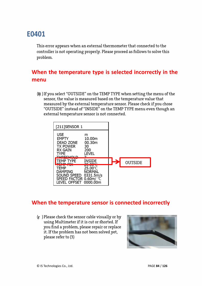
E0401 This error appears when an external thermometer that connected to the
controller is not operating properly. Please proceed as follows to solve this
problem.
When the temperature type is selected incorrectly in the menu
(1) If you select “OUTSIDE” on the TEMP TYPE when setting the menu of the
sensor, the value is measured based on the temperature value that measured by the external temperature sensor. Please check if you chose “OUTSIDE” instead of “INSIDE” on the TEMP TYPE menu even though an external temperature sensor is not connected.
When the temperature sensor is connected incorrectly (2) Please check the sensor cable visually or by
using Multimeter if it is cut or shorted. If you find a problem, please repair or replace it. If the problem has not been solved yet, please refer to (3)
OUTSIDE

© IS Technologies Co., Ltd. PAGE 85 / 126
(3) Please check that the sensor cable is properly connected on the terminal at the exact position. If you find a problem, please connect the sensor cable properly.
(4) If the problem has not been solved yet even though you have confirmed
the process above (2) and (3), please contact our service center or your local dealer.

© IS Technologies Co., Ltd. PAGE 86 / 126
E0201 This error appears when the flash memory inside controller is not operating
properly. Please proceed as follows to solve the problem.
Logging data Recovery If the flash memory is defective, it is difficult to recover the stored data. For
the recovery of the lost data, you will need to send the product to our service
center for repair.
Memory Reset (1) Please try to reset the flash memory at
the menu.
(2) Please refer to the menu directory as
follows. All data will be deleted and the memory will be rest.
(3) If the problem continues, please contact
our service center or your local dealer.

© IS Technologies Co., Ltd. PAGE 87 / 126
E0202 (1) This error appears when the EEPROM memory inside controller is not
operating properly. Please proceed as follows to solve the problem.
(2) Please contact our service center immediately. Do not attempt to fix it
yourself
(EEPROM memory stores the important information about the product and
cannot be handled by non-experts. If you need specific inspection and repair,
please contact our service center or your local dealer.)
E0203 This error appears when the REAL TIME CLOCK inside of the controller is not
operating properly. Please proceed as follows to solve the problem.
(1) Please contact our service center immediately. Do not attempt to fix it
yourself
(2) REAL TIME CLOCK is sensitive and cannot be handled by non-experts. If you need specific inspection and repair, please contact our service center or your local dealer.

© IS Technologies Co., Ltd. PAGE 88 / 126
E1204 This error appears when the received signal from sensor1 is abnormal. “LE”
will be flashing on the screen. Please proceed as follows to solve the problem.
(1) Check the installation position of the sensor
(2) Please check the strength of the received signal at the Echo Trend graph
on the screen. If the received signal shows lower waveform than the default Threshold value, please check the installation location of the sensor.
[ ]** To see Echo Trend graph, press the down button on the Measuring Mode
till the graph shows up on the screen.
(3) Please make sure that the sensor is installed perpendicularly to the object
you’re measuring. If it is not, please reinstall it correctly.
(4) Check the contamination on the bottom of the sensor
(5) Please check if there is a contaminant
adhering to the radiating surface. If the radiating surface is contaminated, please wipe it with a soft cloth.
Transmitting Signal Receiving Signal

© IS Technologies Co., Ltd. PAGE 89 / 126
Adjust settings menu corresponding to the measurement object
(6) Please check if the measurement object is the ultrasonic absorber (foam,
sludge). If it is, the received signal is attenuated than normal condition. Please adjust TX POWER, RX GAIN, and Threshold value at [ ]menu 211 to set an appropriate status for your environment.
TX POWER: Please change the default value from 30 to 50 ~ 70
RX GAIN: Please change the default ~value from 85 to 90 95
(7) If “LE” appears on the screen repeatedly and received value is lower than
Threshold value, please change the default Threshold value from 4(0.8V) to 3(0.5V). if it is operating normally, “DT” will be displayed on the screen during normal operation.
[ ]** To see Echo Trend graph, press the down button on the Measuring Mode
till the graph shows up on the screen.
Receiving SignalTransmitting Signal

© IS Technologies Co., Ltd. PAGE 90 / 126
(8) Check the bottom distance setting (9) Please check that the value of the EMPTY has been set within the range.
(10) If the problem keeps occurring, please contact our service center or
your local dealer.
E2204 This error appears when the signal from sensor2 is not received normally. “LE”
will be flashing on the screen. Please proceed as follows to solve the problem.
Processing method is the same as the E1204. (Please refer to Page90.)

© IS Technologies Co., Ltd. PAGE 91 / 126
E0204 This error appears when the signals from sensor1 and sensor2 are abnormal.
“LE” will be flashing on the screen. Please proceed as follows to solve the
problem.
Processing method is the same as the E1204. (Please refer to Page 90)

© IS Technologies Co., Ltd. PAGE 92 / 126
APPENDIX A
SF-500S MENU LIST

© IS Technologies Co., Ltd. PAGE 93 / 126
APENDIX A. SF-500S MENU LIST LEVEL (1000)
2rd MENU Range Default UNIT mm/ cm/ m/ in/ yd/ ft meterTEMP UNIT or EMPTY 0.3m~4.5m 1.2mDEAD ZONE 0.25m~4.5m 0.25mTX POWER 1~100 30RX GAIN 0~100 80
THRESHOLD 1[0.1V], 2[0.3V], 3[0.5V], 4[0.8V], 5[0.9V], 6[1.1V], 7[1.3V], 8[1.6V], 9[1.7V], 10[2.0V]
4[0.8V]
TEMP TYPE INSIDE/ OUTSIDE/ FIX INSIDETEMP FIX -30~70 25 TEMP Ambient temperature DAMPING SLOW/ NORMAL/ FAST/ VERY FAST NORMALSOUND SPEED 1~9999 m/s 331.5m/sSOUND SPEED FACTOR -2.0~2.0 m/ 0.60m/
FLOW (2000) > FLOW UNIT(2100)
l/m, ft3/s, gal/min(US), gal/min(UK), MGD(US), MGD(UK), m3/h, m3/d m3/h

© IS Technologies Co., Ltd. PAGE 94 / 126
FLOW (2000) > DEVICE SELECTION(2200)
3rd MENU Range Default 1.Parshall Flume(2210) 1in/ 2in/ 3in/ 6in/ 9in/1ft/ 1.5ft/ 2ft/ 3ft/ 4ft/ 5ft/ 6ft/ 8ft/ 10ft/ 12ft 1in2.Rect. Suppressed(2220) 1ft/ 1.5ft/ 2ft/ 2.5ft/ 3ft/ 4ft/ 5ft/ 6ft/ 8ft/ 10ft 1ft3.Rect. Contracted(2230) 1ft/ 1.5ft/ 2ft/ 2.5ft/ 3ft/ 4ft/ 5ft/ 6ft/ 8ft/ 10ft 1ft4. V-Notch Weir (2240) 22.5°/ 30°/ 45°/ 60°/ 90°/ 120° 22.5° 5. Cipoletti Weir (2250) 1ft/ 1.5ft/ 2ft/ 2.5ft/ 3ft/ 4ft/ 5ft/ 6ft/ 8ft/ 10ft 1ft6.Leopold Lagco Flume(2260) 4in/ 6in/ 8in/ 10in/ 12in/ 15in/ 18in/ 21in/ 24in/ 30in 4in7.Palmer Bowlus Flume(2270) 4in/ 6in/ 8in/ 10in/ 12in/ 15in/ 18in/ 21in/ 24in/ 30in 4in8.H Flume(2280) 0.5H/ 0.75H/ 1.0H/ 1.5H/ 2.0H/ 2.5H/ 3.0H/ 4.5H/ 0.4HS/
0.6HS/ 0.8HS/ 1.0HS/ 3.0HS/ 4.0HS 0.5H
9.TRAPEZOIDAL Flume(2281) Sm.60°V / Lg.60°V / XL 60°V / 3.0' 60°V/ 2"45° WSC / 12" 45° SRCRC/ 2.0' SRCRC
Sm.60°V
FLOW (2000) > DEVICE SELECTION(2200) > 10.DIY Curve/Special (2290)
4th MENU 5th MENU Range Default
DIY CURVE (2291) MAX HEIGHT DEAD ZONE ~ EMPTY 1.2mDIY CURVE 1~20 0.1~200000.0 m3/h 0.1
Q=K*H (PWR) (2292)
K Constant (0.0001~9999.9999) 0.0001PWR Constant (0.001~9.999) 0.001H mm/ cm/ m/ in/ yd/ ft mQ m3/h or gal/h m3/h
Rectangular Weir(2293) Crest Length 0~10m 0.10mSelection 1.Suppressed Weir/ 2.Contraced Weir 1

© IS Technologies Co., Ltd. PAGE 95 / 126
FLOW (2000) > LOW CUT VALUE(2300)
0.00 ~ Max. peak flow 0
FLOW (2000) > HIGH CUT VALUE(2400)
0.00 ~ Max. peak flow 20929.28
FLOW (2000) > FLOW RATE (2600)
0.001~9.999 1
FLOW (2000) > FLOW INDEX (2700)
0.001m~ EMPTY
RELAY (3000) > RELAY1~RELAY3(3100~3300)
3rd MENU 4th MENU Range Default
DETAIL (3210) FUNCTION NONE/ LIMIT/ ALTERNATE/ ALARM NONEGROUP 1,2 1
ON POINT (3220) 0.01~ Max. peak flow unit: 0.01m3/h 0.01OFF POINT (3130) 0.01~ Max. peak flow unit: 0.01m3/h 0.01
RELAY (3000) > SIMULATION (3400)
3rd MENU Range Default RELAY 1 ON/ OFF OFFRELAY 2 ON/ OFF OFFRELAY 3 ON/ OFF OFF

© IS Technologies Co., Ltd. PAGE 96 / 126
CURRENT OUTPUT(4000)
2nd MENU 3rd MENU Range Default
CURRENT OUTPUT 1 (4100)
INPUT TYPE(4110) LEVEL/FLOW FLOW4mA POINT SET(4120) 0.00 ~ Max. peak Flow or (0.00~ EMPTY) 0 m3/h20mA POINT SET(4130) 0.00 ~ Max. peak Flow or (0.00~ EMPTY) 0 m3/hFAIL SAFE CURRENT (4140)
3.8mA/HOLD/22mA 22mA
CURRENT OUTPUT 1 (4200)
INPUT TYPE(4110) LEVEL/FLOW LEVEL4mA POINT SET(4120) 0.00 ~ Max. peak Flow or (0.00~ EMPTY) 020mA POINT SET(4130) 0.00 ~ Max. peak Flow or (0.00~ EMPTY) 0 m3/hFAIL SAFE CURRENT (4140)
3.8mA/HOLD/22mA 22mA
SIMULATION(4300) OUTPUT 1 MEASURE/3.8mA/4mA/12mA/20mA/21mA MEASUREOUTPUT 2 MEASURE/3.8mA/4mA/12mA/20mA/21mA MEASURE
PULSE OUTPUT (5000)
2nd MENU Range Default FUNCTION NONE/USE NONEPULSE WIDTH 0.01~1.00 단위 0.01sec 0.10 sec PULSE VALUE 0.1~999.9 m3, 0~9.99999MG 1 m3

© IS Technologies Co., Ltd. PAGE 97 / 126
COMMUNICATION SETUP (6000)
2nd MENU 3rd MENU Range Default
RS-232 SETUP (6100)
USE ENABLE/ DISABLE ENABLEBAUDRATE 4800, 9600, 14400, 19200, 38400, 57600, 115200 9600PARITY NONE/ ODD/ EVEN NONESTOP BIT 1 or 2 1DATA BIT 8 or 9 8PROTOCOL SONDAR/ KICT/Modbus-RTU/ Modbus-ASCII SONDAR
RS-485 SETUP (6200)
USE ENABLE/ DISABLE DISABLEBAUDRATE 4800, 9600, 14400, 19200, 38400, 57600, 115200 9600PARITY NONE/ ODD/ EVEN NONESTOP BIT 1 or 2 1DATA BIT 8 or 9 8PROTOCOL SONDAR/KICT/ Modbus-RTU/ Modbus-ASCII SONDAR

© IS Technologies Co., Ltd. PAGE 98 / 126
APPENDIX B
RS-232/RS-485 Protocol

© IS Technologies Co., Ltd. PAGE 99 / 126
APPENDIX B. RS-232/RS-485 Protocol 1. SONDAR PROTOCOL
Data Field DATA START System ID YEAR MONTH DAY HOUR MIN.
Byte Number 1 2 3 4 5 6 7 8 9 10 11 12 13 14 15 16 17 18 19 20 21 22 23 24 25 26
Data : D A T A 0 0 2 0 1 3 0 1 0 1 0 0 0 0
Data Field SECOND UNIT SENSOR1 Level SENSOR2 Level SENSOR1-SENSOR2 Level
Byte Number
27 28 29 30 31 32 33 34 35 36 37 38 39 40 41 42 43 44 45 46 47 48 49 50 51 52
Data 0 0 M 0 0 0 0 0 0 0 0 0 0 0 0 0 0 0 0 0 0
Data Field SENSOR1-SENSOR2 Level SENSOR1 Volume SENSOR2 Volume
Byte Number
53 54 55 56 57 58 59 60 61 62 63 64 65 66 67 68 69 70 71 72 73 74 75 76 77 78
Data 0 0 0 0 0 0 0 0 0 0 0 0 0 0 0 0 0 0 0 0 0 0 0 0
Data Field TEMP. UNIT SENSOR1 TEMPERATURE SENSOR2 TEMPERATURE DATA END
Byte Number
79 80 81 82 83 84 85 86 87 88 89 90 91 92 93 94 95 96 97 98 99
Data C +/- 0 0 0 0 . 0 +/- 0 0 0 0 . 0 ₩n ₩r

© IS Technologies Co., Ltd. PAGE 100 / 126

© IS Technologies Co., Ltd. PAGE 101 / 126
2. DATA FORMAT
• System ID: System ID • YEAR/MONTH/DAY/HOUR/MINUTE/SECOND : DATA LOGGING TIME • UNIT: MEASUREMENT UNIT
UNIT
mm cm m ft in yd
• SENSOR1 Level: Measurement value of SENSOR1. • SENSOR2 Level: Measurement value of SENSOR2. • SENSOR1-SENSOR2 Level: Differentiation subtracted SENSOR2 from SENSOR1 • SENSOR2-SENSOR1 Level: Differentiation subtracted SENSOR1 from SENSOR2. • SENSOR1 Volume: Measurement value of SENSOR1 Volume. • SENSOR2 Volume: Measurement value of SENSOR2 Volume. • Temp. unit : the unit of temperature
Temperature unit
C
F
• SENSOR1 Temperature: Temperature of SENSOR1 • SENSOR2 Temperature: Temperature of SENSOR1 • DATA END: The sign of DATA end. “\n\r(Line feed(0x12),carrage return(0x15))”

© IS Technologies Co., Ltd. PAGE 102 / 126
2. BKCM PROTOCOL
“This protocol is designed for a company. It isn’t printed in this manual.”

© IS Technologies Co., Ltd. PAGE 103 / 126
3. Modbus SF-500S provides Modbus RTU and Modbus ASCII. It is Read Holding Registers only, Modbus ID is available between
~1 247. Modbus ID setting menu locates as below.
• SYSTEM SETUP->SYSTEM ID->Modbus ID
Type Description Start Register Register Offset
Registers Data Description
Hex Decimal Hex Decimal
ID Product code 8001 32769 8000 32768 1
0 = Level(SF-500S) 10 = Flow(SF-500S)
20 = Sludge(SL-300S)
Unit
Measurement Unit (Level) 8002 32770 8001 32769 1
1 = Meter
2 = Millimeter
3 = Centimeter
4 = feet
5 = inch
6 = yard
Temperature Unit 8004 32772 8003 32771 1 0 =
1 =

© IS Technologies Co., Ltd. PAGE 104 / 126
Type Description Start Register Register Offset
Registers Data Description Hex Decimal Hex Decimal
Data
Distance1 8011 32785 8010 32784 2 SENSOR1 Distance float
Level1 8013 32787 8012 32786 2 SENSOR1 level float
Space1 8015 32789 8014 32788 2 SENSOR1 space float
Volume1 8017 32791 8016 32790 2 SENSOR1 volume float
Distance2 8019 32793 8018 32792 2 SENSOR2 Distance float
Level2 801B 32795 801A 32794 2 SENSOR2 level float
Data
Space2 801D 32797 801C 32796 2 SENSOR2 space float
Volume2 801F 32799 801E 32798 2 SENSOR2 volume float
Temp 1(inside) 802B 32811 802A 32810 2 SENSOR1 temperature float
Temp 2(inside) 802D 32813 802C 32812 2 SENSOR2 temperature float
Temp (outside) 802F 32815 802E 32814 2 Outside temperature float
Relay Relay control status 8031 32817 8030 32816 1
Bit Mapped
0bxxxx xxx0 / (0x00) Relay 1 Off 0bxxxx xxx1 / (0x01) Relay 1 On 0bxxxx xx0x / (0x00) Relay 2 Off 0bxxxx xx1x / (0x02) Relay 2 On 0bxxxx x0xx / (0x00) Relay 3 Off 0bxxxx x1xx / (0x04) Relay 3 On 0bxxxx 0xxx / (0x00) Relay 4 Off 0bxxxx 1xxx / (0x08) Relay 4 On 0bxxx0 xxxx / (0x00) Relay 5 Off 0bxxx1 xxxx / (0x10) Relay 5 On 0bxx0x xxxx / (0x00) Relay 6 Off 0bxx1x xxxx / (0x20) Relay 6 On

© IS Technologies Co., Ltd. PAGE 105 / 126
Request PDU Example • Product code Request
Function Code Data Request
Register Offset Quantity
0 X 03 0 X 8000 0 X 0001
• Distance, Level, Space, Volume Request
Function Code Data Request
Register Offset Quantity
0 X 03 0 X 8000 0 X 0002
0 X 03 0 X 8012 0 X 0002
0 X 03 0 X 8014 0 X 0002
0 X 03 0 X 8016 0 X 0002
Modbus Register Data type • Data field: 4byte float type • ID, UNIT, Relay field: Unsigned short(2byte) type

© IS Technologies Co., Ltd. PAGE 106 / 126
APPENDIX C Volume Table

© IS Technologies Co., Ltd. PAGE 107 / 126
APPENDIX C. Volume Table VERTICAL CYLINDER - CONICAL BOTTOM D[m] 1 1 1 3 3 3 5 5 5 7 7 7 9 9 9 A[m] 0.5 1.0 2.0 0.5 1.0 2.0 0.5 1.0 2.0 0.5 1.0 2.0 0.5 1.0 2.0
h[m]
0.5 0.13 0.03 0.01 1.18 0.29 0.07 3.27 0.82 0.20 6.41 1.60 0.40 10.60 2.65 0.66
1.0 0.52 0.26 0.07 4.71 2.36 0.59 13.09 6.54 1.64 25.66 12.83 3.21 42.41 21.21 5.30
1.5 0.92 0.65 0.22 8.25 5.89 1.99 22.91 16.36 5.52 44.90 32.07 10.82 74.22 53.01 17.89
2.0 1.31 1.05 0.52 11.78 9.42 4.71 32.72 26.18 13.09 64.14 51.31 25.66 106.03 84.82 42.41
2.5 1.70 1.44 0.92 15.32 12.96 8.25 42.54 36.00 22.91 83.38 70.55 44.90 137.84 116.63 74.22
3.0 2.09 1.83 1.31 18.85 16.49 11.78 52.36 45.81 32.72 102.63 89.80 64.14 169.65 148.44 106.03
3.5 2.49 2.23 1.70 22.38 20.03 15.32 62.18 55.63 42.54 121.87 109.04 83.38 201.45 180.25 137.84
4.0 2.88 2.62 2.09 25.92 23.56 18.85 71.99 65.45 52.36 141.11 128.28 102.63 233.26 212.06 169.65
4.5 3.27 3.01 2.49 29.45 27.10 22.38 81.81 75.27 62.18 160.35 147.52 121.87 265.07 243.87 201.45
5.0 3.67 3.40 2.88 32.99 30.63 25.92 91.63 85.08 71.99 179.59 166.77 141.11 296.88 275.67 233.26
5.5 4.06 3.80 3.27 36.52 34.16 29.45 101.45 94.90 81.81 198.84 186.01 160.35 328.69 307.48 265.07
6.0 4.45 4.19 3.67 40.06 37.70 32.99 111.26 104.72 91.63 218.08 205.25 179.59 360.50 339.29 296.88
6.5 4.84 4.58 4.06 43.59 41.23 36.52 121.08 114.54 101.45 237.32 224.49 198.84 392.31 371.10 328.69
7.0 5.24 4.97 4.45 47.12 44.77 40.06 130.90 124.35 111.26 256.56 243.74 218.08 424.12 402.91 360.50
7.5 5.63 5.37 4.84 50.66 48.30 43.59 140.72 134.17 121.08 275.81 262.98 237.32 455.92 434.72 392.31
8.0 6.02 5.76 5.24 54.19 51.84 47.12 150.53 143.99 130.90 295.05 282.22 256.56 487.73 466.53 424.12
8.5 6.41 6.15 5.63 57.73 55.37 50.66 160.35 153.81 140.72 314.29 301.46 275.81 519.54 498.34 455.92
9.0 6.81 6.54 6.02 61.26 58.90 54.19 170.17 163.62 150.53 333.53 320.70 295.05 551.35 530.14 487.73
9.5 7.20 6.94 6.41 64.80 62.44 57.73 179.99 173.44 160.35 352.77 339.95 314.29 583.16 561.95 519.54

© IS Technologies Co., Ltd. PAGE 108 / 126
10.0 7.59 7.33 6.81 68.33 65.97 61.26 189.80 183.26 170.17 372.02 359.19 333.53 614.97 593.76 551.35
10.5 7.98 7.72 7.20 71.86 69.51 64.80 199.62 193.08 179.99 391.26 378.43 352.77 646.78 625.57 583.16
• D: Tank diameter • A: Bottom length • h: Level height • unit: m3

© IS Technologies Co., Ltd. PAGE 109 / 126
VERTICAL CYLINDER - CONICAL BOTTOM D[m] 1 1 1 3 3 3 5 5 5 7 7 7 9 9 9 A[m] 0.5 1.0 2.0 0.5 1.0 2.0 0.5 1.0 2.0 0.5 1.0 2.0 0.5 1.0 2.0
h[m]
11.0 8.38 8.12 7.59 75.40 73.04 68.33 209.44 202.89 189.80 410.50 397.67 372.02 678.58 657.38 614.97
11.5 8.77 8.51 7.98 78.93 76.58 71.86 219.26 212.71 199.62 429.74 416.92 391.26 710.39 689.19 646.78
12.0 9.16 8.90 8.38 82.47 80.11 75.40 229.07 222.53 209.44 448.99 436.16 410.50 742.20 721.00 678.58
12.5 9.56 9.29 8.77 86.00 83.64 78.93 238.89 232.35 219.26 468.23 455.40 429.74 774.01 752.80 710.39
13.0 9.95 9.69 9.16 89.54 87.18 82.47 248.71 242.16 229.07 487.47 474.64 448.99 805.82 784.61 742.20
13.5 10.34 10.08 9.56 93.07 90.71 86.00 258.53 251.98 238.89 506.71 493.88 468.23 837.63 816.42 774.01
14.0 10.73 10.47 9.95 96.60 94.25 89.54 268.34 261.80 248.71 525.95 513.13 487.47 869.44 848.23 805.82
14.5 11.13 10.86 10.34 100.14 97.78 93.07 278.16 271.62 258.53 545.20 532.37 506.71 901.24 880.04 837.63
15.0 11.52 11.26 10.73 103.67 101.32 96.60 287.98 281.43 268.34 564.44 551.61 525.95 933.05 911.85 869.44
• D: Tank diameter • A: Bottom length • h: Level height • unit: m3

© IS Technologies Co., Ltd. PAGE 110 / 126
VERTICAL CYLINDER - ELLIPSOIDAL BOTTOM D[m] 1 1 1 3 3 3 5 5 5 7 7 7 9 9 9 A[m] 0.5 1.0 2.0 0.5 1.0 2.0 0.5 1.0 2.0 0.5 1.0 2.0 0.5 1.0 2.0
h[m]
0.5 0.26 0.16 0.09 2.36 1.47 0.81 6.54 4.09 2.25 12.83 8.02 4.41 21.21 13.25 7.29
1.0 0.65 0.52 0.33 5.89 4.71 2.95 16.36 13.09 8.18 32.07 25.66 16.04 53.01 42.41 26.51
1.5 1.05 0.92 0.66 9.42 8.25 5.96 26.18 22.91 16.57 51.31 44.90 32.47 84.82 74.22 53.68
2.0 1.44 1.31 1.05 12.96 11.78 9.42 36.00 32.72 26.18 70.55 64.14 51.31 116.63 106.03 84.82
2.5 1.83 1.70 1.44 16.49 15.32 12.96 45.81 42.54 36.00 89.80 83.38 70.55 148.44 137.84 116.63
3.0 2.23 2.09 1.83 20.03 18.85 16.49 55.63 52.36 45.81 109.04 102.63 89.80 180.25 169.65 148.44
3.5 2.62 2.49 2.23 23.56 22.38 20.03 65.45 62.18 55.63 128.28 121.87 109.04 212.06 201.45 180.25
4.0 3.01 2.88 2.62 27.10 25.92 23.56 75.27 71.99 65.45 147.52 141.11 128.28 243.87 233.26 212.06
4.5 3.40 3.27 3.01 30.63 29.45 27.10 85.08 81.81 75.27 166.77 160.35 147.52 275.67 265.07 243.87
5.0 3.80 3.67 3.40 34.16 32.99 30.63 94.90 91.63 85.08 186.01 179.59 166.77 307.48 296.88 275.67
5.5 4.19 4.06 3.80 37.70 36.52 34.16 104.72 101.45 94.90 205.25 198.84 186.01 339.29 328.69 307.48
6.0 4.58 4.45 4.19 41.23 40.06 37.70 114.54 111.26 104.72 224.49 218.08 205.25 371.10 360.50 339.29
6.5 4.97 4.84 4.58 44.77 43.59 41.23 124.35 121.08 114.54 243.74 237.32 224.49 402.91 392.31 371.10
7.0 5.37 5.24 4.97 48.30 47.12 44.77 134.17 130.90 124.35 262.98 256.56 243.74 434.72 424.12 402.91
7.5 5.76 5.63 5.37 51.84 50.66 48.30 143.99 140.72 134.17 282.22 275.81 262.98 466.53 455.92 434.72
8.0 6.15 6.02 5.76 55.37 54.19 51.84 153.81 150.53 143.99 301.46 295.05 282.22 498.34 487.73 466.53
8.5 6.54 6.41 6.15 58.90 57.73 55.37 163.62 160.35 153.81 320.70 314.29 301.46 530.14 519.54 498.34
9.0 6.94 6.81 6.54 62.44 61.26 58.90 173.44 170.17 163.62 339.95 333.53 320.70 561.95 551.35 530.14
9.5 7.33 7.20 6.94 65.97 64.80 62.44 183.26 179.99 173.44 359.19 352.77 339.95 593.76 583.16 561.95
10.0 7.72 7.59 7.33 69.51 68.33 65.97 193.08 189.80 183.26 378.43 372.02 359.19 625.57 614.97 593.76
10.5 8.12 7.98 7.72 73.04 71.86 69.51 202.89 199.62 193.08 397.67 391.26 378.43 657.38 646.78 625.57
11.0 8.51 8.38 8.12 76.58 75.40 73.04 212.71 209.44 202.89 416.92 410.50 397.67 689.19 678.58 657.38

© IS Technologies Co., Ltd. PAGE 111 / 126
11.5 8.90 8.77 8.51 80.11 78.93 76.58 222.53 219.26 212.71 436.16 429.74 416.92 721.00 710.39 689.19
12.0 9.29 9.16 8.90 83.64 82.47 80.11 232.35 229.07 222.53 455.40 448.99 436.16 752.80 742.20 721.00
12.5 9.69 9.56 9.29 87.18 86.00 83.64 242.16 238.89 232.35 474.64 468.23 455.40 784.61 774.01 752.80
• D: Tank diameter • A: Bottom length • h: Level height • unit: m3

© IS Technologies Co., Ltd. PAGE 112 / 126
VERTICAL CYLINDER - ELLIPSOIDAL BOTTOM D[m] 1 1 1 3 3 3 5 5 5 7 7 7 9 9 9 A[m] 0.5 1.0 2.0 0.5 1.0 2.0 0.5 1.0 2.0 0.5 1.0 2.0 0.5 1.0 2.0
h[m]
13.0 10.08 9.95 9.69 90.71 89.54 87.18 251.98 248.71 242.16 493.88 487.47 474.64 816.42 805.82 784.61
13.5 10.47 10.34 10.08 94.25 93.07 90.71 261.80 258.53 251.98 513.13 506.71 493.88 848.23 837.63 816.42
14.0 10.86 10.73 10.47 97.78 96.60 94.25 271.62 268.34 261.80 532.37 525.95 513.13 880.04 869.44 848.23
14.5 11.26 11.13 10.86 101.32 100.14 97.78 281.43 278.16 271.62 551.61 545.20 532.37 911.85 901.24 880.04
15.0 11.65 11.52 11.26 104.85 103.67 101.32 291.25 287.98 281.43 570.85 564.44 551.61 943.66 933.05 911.85

© IS Technologies Co., Ltd. PAGE 113 / 126
VERTICAL CYLINDER - SPHERICAL BOTTOM D[m] 1 1 1 3 3 3 5 5 5 7 7 7 9 9 9 A[m] 0.5 1.0 2.0 0.5 1.0 2.0 0.5 1.0 2.0 0.5 1.0 2.0 0.5 1.0 2.0
h[m]
0.5 0.26 0.36 0.70 1.83 1.15 1.10 4.97 2.72 1.88 9.69 5.07 3.06 15.97 8.21 4.63
1.0 0.65 0.92 2.29 5.37 4.06 3.86 14.79 10.34 7.00 28.93 19.77 11.72 47.78 32.33 18.00
1.5 1.05 1.31 3.98 8.90 7.59 7.51 24.61 20.16 14.58 48.17 39.01 25.18 79.59 64.14 39.32
2.0 1.44 1.70 4.97 12.44 11.13 11.26 34.43 29.98 23.82 67.41 58.25 42.67 111.40 95.95 67.81
2.5 1.83 2.09 5.37 15.97 14.66 14.79 44.24 39.79 33.64 86.66 77.49 61.92 143.20 127.76 99.61
3.0 2.23 2.49 5.76 19.50 18.20 18.33 54.06 49.61 43.46 105.90 96.73 81.16 175.01 159.57 131.42
3.5 2.62 2.88 6.15 23.04 21.73 21.86 63.88 59.43 53.28 125.14 115.98 100.40 206.82 191.38 163.23
4.0 3.01 3.27 6.54 26.57 25.26 25.39 73.70 69.25 63.09 144.38 135.22 119.64 238.63 223.18 195.04
4.5 3.40 3.67 6.94 30.11 28.80 28.93 83.51 79.06 72.91 163.62 154.46 138.88 270.44 254.99 226.85
5.0 3.80 4.06 7.33 33.64 32.33 32.46 93.33 88.88 82.73 182.87 173.70 158.13 302.25 286.80 258.66
5.5 4.19 4.45 7.72 37.18 35.87 36.00 103.15 98.70 92.55 202.11 192.95 177.37 334.06 318.61 290.47
6.0 4.58 4.84 8.12 40.71 39.40 39.53 112.97 108.52 102.36 221.35 212.19 196.61 365.86 350.42 322.28
6.5 4.97 5.24 8.51 44.24 42.94 43.07 122.78 118.33 112.18 240.59 231.43 215.85 397.67 382.23 354.08
7.0 5.37 5.63 8.90 47.78 46.47 46.60 132.60 128.15 122.00 259.84 250.67 235.10 429.48 414.04 385.89
7.5 5.76 6.02 9.29 51.31 50.00 50.13 142.42 137.97 131.82 279.08 269.92 254.34 461.29 445.84 417.70
8.0 6.15 6.41 9.69 54.85 53.54 53.67 152.24 147.79 141.63 298.32 289.16 273.58 493.10 477.65 449.51
8.5 6.54 6.81 10.08 58.38 57.07 57.20 162.05 157.60 151.45 317.56 308.40 292.82 524.91 509.46 481.32
9.0 6.94 7.20 10.47 61.92 60.61 60.74 171.87 167.42 161.27 336.80 327.64 312.06 556.72 541.27 513.13
9.5 7.33 7.59 10.86 65.45 64.14 64.27 181.69 177.24 171.09 356.05 346.88 331.31 588.53 573.08 544.94
10.0 7.72 7.98 11.26 68.98 67.68 67.81 191.51 187.06 180.90 375.29 366.13 350.55 620.33 604.89 576.74
10.5 8.12 8.38 11.65 72.52 71.21 71.34 201.32 196.87 190.72 394.53 385.37 369.79 652.14 636.70 608.55
11.0 8.51 8.77 12.04 76.05 74.74 74.87 211.14 206.69 200.54 413.77 404.61 389.03 683.95 668.50 640.36
11.5 8.90 9.16 12.44 79.59 78.28 78.41 220.96 216.51 210.36 433.02 423.85 408.28 715.76 700.31 672.17
12.0 9.29 9.56 12.83 83.12 81.81 81.94 230.78 226.33 220.17 452.26 443.10 427.52 747.57 732.12 703.98
12.5 9.69 9.95 13.22 86.66 85.35 85.48 240.59 236.14 229.99 471.50 462.34 446.76 779.38 763.93 735.79

© IS Technologies Co., Ltd. PAGE 114 / 126
VERTICAL CYLINDER - SPHERICAL BOTTOM
D[m] 1 1 1 3 3 3 5 5 5 7 7 7 9 9 9 A[m] 0.5 1.0 2.0 0.5 1.0 2.0 0.5 1.0 2.0 0.5 1.0 2.0 0.5 1.0 2.0
h[m]
13.0 10.08 10.34 13.61 90.19 88.88 89.01 250.41 245.96 239.81 490.74 481.58 466.00 811.19 795.74 767.60
13.5 10.47 10.73 14.01 93.72 92.42 92.55 260.23 255.78 249.63 509.99 500.82 485.25 842.99 827.55 799.40
14.0 10.86 11.13 14.40 97.26 95.95 96.08 270.05 265.60 259.44 529.23 520.06 504.49 874.80 859.36 831.21
14.5 11.26 11.52 14.79 100.79 99.48 99.61 279.86 275.41 269.26 548.47 539.31 523.73 906.61 891.17 863.02
15.0 11.65 11.91 15.18 104.33 103.02 103.15 289.68 285.23 279.08 567.71 558.55 542.97 938.42 922.97 894.83
• D: Tank diameter • A: Bottom length • h: Level height • unit: m3

© IS Technologies Co., Ltd. PAGE 115 / 126
VERTICAL CYLINDER - FLAT BOTTOM D[m] 1 1 1 3 3 3 5 5 5 7 7 7 9 9 9
h[m]
0.5 0.39 0.39 0.39 3.53 3.53 3.53 9.82 9.82 9.82 19.24 19.24 19.24 31.81 31.81 31.81
1.0 0.79 0.79 0.79 7.07 7.07 7.07 19.63 19.63 19.63 38.48 38.48 38.48 63.62 63.62 63.62
1.5 1.18 1.18 1.18 10.60 10.60 10.60 29.45 29.45 29.45 57.73 57.73 57.73 95.43 95.43 95.43
2.0 1.57 1.57 1.57 14.14 14.14 14.14 39.27 39.27 39.27 76.97 76.97 76.97 127.23 127.23 127.23
2.5 1.96 1.96 1.96 17.67 17.67 17.67 49.09 49.09 49.09 96.21 96.21 96.21 159.04 159.04 159.04
3.0 2.36 2.36 2.36 21.21 21.21 21.21 58.90 58.90 58.90 115.45 115.45 115.45 190.85 190.85 190.85
3.5 2.75 2.75 2.75 24.74 24.74 24.74 68.72 68.72 68.72 134.70 134.70 134.70 222.66 222.66 222.66
4.0 3.14 3.14 3.14 28.27 28.27 28.27 78.54 78.54 78.54 153.94 153.94 153.94 254.47 254.47 254.47
4.5 3.53 3.53 3.53 31.81 31.81 31.81 88.36 88.36 88.36 173.18 173.18 173.18 286.28 286.28 286.28
5.0 3.93 3.93 3.93 35.34 35.34 35.34 98.17 98.17 98.17 192.42 192.42 192.42 318.09 318.09 318.09
5.5 4.32 4.32 4.32 38.88 38.88 38.88 107.99 107.99 107.99 211.66 211.66 211.66 349.89 349.89 349.89
6.0 4.71 4.71 4.71 42.41 42.41 42.41 117.81 117.81 117.81 230.91 230.91 230.91 381.70 381.70 381.70
6.5 5.11 5.11 5.11 45.95 45.95 45.95 127.63 127.63 127.63 250.15 250.15 250.15 413.51 413.51 413.51
7.0 5.50 5.50 5.50 49.48 49.48 49.48 137.44 137.44 137.44 269.39 269.39 269.39 445.32 445.32 445.32
7.5 5.89 5.89 5.89 53.01 53.01 53.01 147.26 147.26 147.26 288.63 288.63 288.63 477.13 477.13 477.13
8.0 6.28 6.28 6.28 56.55 56.55 56.55 157.08 157.08 157.08 307.88 307.88 307.88 508.94 508.94 508.94
8.5 6.68 6.68 6.68 60.08 60.08 60.08 166.90 166.90 166.90 327.12 327.12 327.12 540.75 540.75 540.75
9.0 7.07 7.07 7.07 63.62 63.62 63.62 176.71 176.71 176.71 346.36 346.36 346.36 572.56 572.56 572.56
9.5 7.46 7.46 7.46 67.15 67.15 67.15 186.53 186.53 186.53 365.60 365.60 365.60 604.36 604.36 604.36
10.0 7.85 7.85 7.85 70.69 70.69 70.69 196.35 196.35 196.35 384.85 384.85 384.85 636.17 636.17 636.17
10.5 8.25 8.25 8.25 74.22 74.22 74.22 206.17 206.17 206.17 404.09 404.09 404.09 667.98 667.98 667.98
11.0 8.64 8.64 8.64 77.75 77.75 77.75 215.98 215.98 215.98 423.33 423.33 423.33 699.79 699.79 699.79
11.5 9.03 9.03 9.03 81.29 81.29 81.29 225.80 225.80 225.80 442.57 442.57 442.57 731.60 731.60 731.60
12.0 9.42 9.42 9.42 84.82 84.82 84.82 235.62 235.62 235.62 461.81 461.81 461.81 763.41 763.41 763.41
12.5 9.82 9.82 9.82 88.36 88.36 88.36 245.44 245.44 245.44 481.06 481.06 481.06 795.22 795.22 795.22
13.0 10.21 10.21 10.21 91.89 91.89 91.89 255.25 255.25 255.25 500.30 500.30 500.30 827.02 827.02 827.02

© IS Technologies Co., Ltd. PAGE 116 / 126
VERTICAL CYLINDER - FLAT BOTTOM D[m] 1 1 1 3 3 3 5 5 5 7 7 7 9 9 9
h[m]
13.5 10.60 10.60 10.60 95.43 95.43 95.43 265.07 265.07 265.07 519.54 519.54 519.54 858.83 858.83 858.83
14.0 11.00 11.00 11.00 98.96 98.96 98.96 274.89 274.89 274.89 538.78 538.78 538.78 890.64 890.64 890.64
14.5 11.39 11.39 11.39 102.49 102.49 102.49 284.71 284.71 284.71 558.03 558.03 558.03 922.45 922.45 922.45
15.0 11.78 11.78 11.78 106.03 106.03 106.03 294.52 294.52 294.52 577.27 577.27 577.27 954.26 954.26 954.26
• D: Tank diameter • A: Bottom length • h: Level height • unit: m3

© IS Technologies Co., Ltd. PAGE 117 / 126
HORIZONTAL CYLINDER - CONICAL HEAD D[m] 1 1 1 3 3 3 5 5 5 7 7 7 9 9 9 A[m] 0.5 1.0 2.0 0.5 1.0 2.0 0.5 1.0 2.0 0.5 1.0 2.0 0.5 1.0 2.0
h[m]
0.5 2.09 2.23 2.49 3.97 4.07 4.27 5.19 5.27 5.43 6.17 6.24 6.38 7.01 7.07 7.20 1.0 4.19 4.45 4.97 10.81 11.31 12.32 14.40 14.83 15.68 17.24 17.61 18.35 19.65 19.99 20.66 1.5 18.85 20.03 22.38 25.87 26.96 29.16 31.22 32.20 34.17 35.74 36.63 38.42
2.0 26.89 28.74 32.45 38.75 40.82 44.97 47.29 49.21 53.06 54.40 56.18 59.72
2.5 33.73 35.98 40.50 52.36 55.63 62.18 64.87 68.05 74.41 75.08 78.06 84.02
3.0 37.70 40.06 44.77 65.97 70.44 79.38 83.48 88.18 97.59 97.32 101.83 110.84 3.5 78.85 84.30 95.20 102.63 109.04 121.87 120.74 127.07 139.72 4.0 90.32 96.43 108.67 121.77 129.90 146.14 144.98 153.36 170.14 4.5 99.53 106.00 118.93 140.38 150.03 169.33 169.65 180.25 201.45
5.0 104.72 111.26 124.35 157.96 168.87 190.68 194.32 207.13 232.77
5.5 174.03 185.88 209.57 218.55 233.43 263.18
6.0 188.02 200.47 225.38 241.97 258.67 292.07 6.5 199.08 211.84 237.36 264.21 282.44 318.89 7.0 205.25 218.08 243.74 284.89 304.32 343.19 7.5 303.55 323.86 364.49
8.0 319.64 340.51 382.25
8.5 332.28 353.42 395.71
• D: Tank diameter • A: Bottom length • h: Level height • unit: m3

© IS Technologies Co., Ltd. PAGE 118 / 126
HORIZONTAL CYLINDER - ELLIPSOIDAL HEAD D[m] 1 1 1 3 3 3 5 5 5 7 7 7 9 9 9 A[m] 0.5 1.0 2.0 0.5 1.0 2.0 0.5 1.0 2.0 0.5 1.0 2.0 0.5 1.0 2.0
h[m]
0.5 2.23 2.49 3.01 4.22 4.57 5.27 5.48 5.84 6.58 6.47 6.85 7.60 7.33 7.71 8.46
1.0 4.45 4.97 6.02 11.53 12.76 15.20 15.34 16.70 19.42 18.28 19.70 22.55 20.77 22.23 25.14
1.5 20.03 22.38 27.10 27.60 30.43 36.08 33.26 36.29 42.35 37.99 41.13 47.41
2.0 28.52 32.01 38.99 41.28 45.89 55.10 50.45 55.54 65.71 57.99 63.34 74.04
2.5 35.83 40.20 48.92 55.63 62.18 75.27 69.17 76.65 91.61 80.10 88.10 104.10
3.0 40.06 44.77 54.19 69.99 78.47 95.43 88.87 98.97 119.16 103.81 114.81 136.80
3.5 83.67 93.93 114.45 109.04 121.87 147.52 128.67 142.92 171.43
4.0 95.93 107.65 131.11 129.21 144.77 175.89 154.28 171.96 207.33
4.5 105.79 118.51 143.96 148.91 167.08 203.43 180.25 201.45 243.87
5.0 111.26 124.35 150.53 167.63 188.20 229.34 206.22 230.95 280.40
5.5 184.82 207.44 252.70 231.83 259.99 316.30
6.0 199.80 224.03 272.50 256.69 288.10 350.94
6.5 211.60 236.89 287.45 280.40 314.81 383.63
7.0 218.08 243.74 295.05 302.51 339.57 413.69
7.5 322.51 361.78 440.32
8.0 339.72 380.68 462.59
8.5 353.17 395.20 479.27
9.0 360.50 402.91 487.73

© IS Technologies Co., Ltd. PAGE 119 / 126
HORIZONTAL CYLINDER - GUPPY HEAD D[m] 1 1 1 3 3 3 5 5 5 7 7 7 9 9 9 A[m] 0.5 1.0 2.0 0.5 1.0 2.0 0.5 1.0 2.0 0.5 1.0 2.0 0.5 1.0 2.0
h[m]
0.5 2.04 2.11 2.26 3.92 3.97 4.08 5.15 5.19 5.27 6.14 6.17 6.24 6.98 7.01 7.08
1.0 4.19 4.45 4.97 10.58 10.85 11.39 14.20 14.42 14.86 17.05 17.24 17.63 19.49 19.66 20.00
1.5 18.35 19.03 20.38 25.35 25.94 27.10 30.74 31.26 32.28 35.31 35.77 36.69
2.0 26.28 27.53 30.03 37.81 38.95 41.22 46.38 47.40 49.43 53.56 54.48 56.32
2.5 33.36 35.25 39.04 50.97 52.85 56.62 63.41 65.13 68.56 73.67 75.24 78.39
3.0 37.70 40.06 44.77 64.30 67.09 72.68 81.38 84.00 89.22 95.23 97.65 102.48
3.5 77.23 81.05 88.70 99.90 103.60 110.98 117.87 121.33 128.24
4.0 89.10 94.00 103.80 118.59 123.53 133.40 141.28 145.97 155.35
4.5 98.97 104.87 116.68 137.05 143.37 156.01 165.15 171.25 183.45
5.0 104.72 111.26 124.35 154.85 162.65 178.24 189.18 196.86 212.23
5.5 171.50 180.81 199.42 213.08 222.48 241.30
6.0 186.33 197.10 218.64 236.52 247.77 270.26
6.5 198.37 210.42 234.52 259.15 272.31 298.64
7.0 205.25 218.08 243.74 280.56 295.67 325.89
7.5 300.26 317.28 351.32
8.0 317.57 336.37 373.97
8.5 331.44 351.75 392.37
9.0 339.29 360.50 402.91

© IS Technologies Co., Ltd. PAGE 120 / 126
HORIZONTAL CYLINDER - SPHERICAL HEAD D[m] 1 1 1 3 3 3 5 5 5 7 7 7 9 9 9 A[m] 0.2 0.3 0.5 0.5 1.0 1.5 1.0 2.0 2.5 1.0 3.5 5.0 1.0 3.0 4.5
h[m]
0.5 3.62 3.67 3.80 7.16 7.46 8.02 9.54 10.25 11.03 11.26 12.64 12.02 13.45 13.74 17.01 1.0 7.23 7.33 7.59 19.43 20.55 22.23 26.83 29.63 31.97 31.81 37.42 35.18 38.03 39.54 51.45 1.5 33.64 35.87 38.88 48.55 54.40 58.73 58.06 70.27 65.74 69.72 73.52 98.30
2.0 47.86 51.18 55.53 72.97 82.49 89.05 88.42 109.06 101.77 106.86 114.03 155.10
2.5 60.12 64.28 69.74 98.70 112.18 121.08 121.70 152.09 141.73 148.35 159.89 220.00
3.0 67.28 71.73 77.75 124.42 141.87 153.12 156.86 197.89 184.25 193.33 210.07 291.45 3.5 148.84 169.96 183.44 192.95 245.04 228.02 240.99 263.66 368.01 4.0 170.56 194.74 210.20 229.03 292.20 271.80 290.65 319.77 448.34 4.5 187.86 214.11 231.13 264.19 338.00 314.32 341.61 377.55 531.16
5.0 197.40 224.36 242.16 297.47 381.03 354.28 393.22 436.16 615.23
5.5 327.83 419.82 390.31 444.83 494.77 699.29
6.0 354.08 452.67 420.87 495.80 552.55 782.12 6.5 374.63 477.45 444.03 545.45 608.66 862.45 7.0 385.89 490.09 593.12 662.25 939.01 7.5 638.09 712.43 1010.45
8.0 679.59 758.28 1075.36
8.5 716.73 798.80 1132.16
9.0 748.41 832.78 1179.01 9.5 773.00 858.58 1213.45 10.0 786.45 872.32 1230.46

© IS Technologies Co., Ltd. PAGE 121 / 126
HORIZONTAL CYLINDER - FLAT HEAD D[m] 1 2 3 4 5 6 7 8 9 10 11 12 13 14 15
h[m]
0.5 0.39 0.61 0.77 0.91 1.02 1.13 1.22 1.31 1.39 1.47 1.54 1.61 1.68 1.74 1.81 1.0 0.79 1.57 2.06 2.46 2.80 3.10 3.37 3.63 3.86 4.09 4.30 4.50 4.69 4.88 5.06 1.5 2.53 3.53 4.30 4.95 5.53 6.05 6.52 6.97 7.39 7.78 8.16 8.52 8.86 9.20 2.0 3.14 5.01 6.28 7.33 8.25 9.07 9.83 10.53 11.18 11.80 12.39 12.95 13.49 14.01 2.5 6.29 8.26 9.82 11.15 12.34 13.42 14.42 15.35 16.24 17.07 17.87 18.63 19.36 3.0 7.07 10.11 12.30 14.14 15.75 17.22 18.56 19.82 21.00 22.11 23.17 24.19 25.16 3.5 11.66 14.68 17.12 19.24 21.14 22.88 24.50 26.01 27.44 28.80 30.10 31.34 4.0 12.57 16.84 20.02 22.73 25.13 27.32 29.34 31.22 33.00 34.69 36.29 37.83 4.5 18.61 22.75 26.15 29.12 31.81 34.28 36.58 38.74 40.78 42.73 44.59 5.0 19.63 25.18 29.41 33.05 36.30 39.27 42.02 44.60 47.04 49.35 51.56 5.5 27.15 32.44 36.85 40.73 44.26 47.52 50.56 53.42 56.13 58.72 6.0 28.27 35.11 40.44 45.05 49.20 53.01 56.55 59.87 63.02 66.01 6.5 37.26 43.74 49.20 54.04 58.46 62.54 66.37 69.97 73.40 7.0 38.48 46.64 53.09 58.72 63.81 68.49 72.86 76.97 80.86 7.5 48.96 56.65 63.19 69.02 74.36 79.31 83.96 88.36 8.0 50.27 59.75 67.36 74.04 80.10 85.69 90.92 95.85 8.5 62.23 71.15 78.80 85.66 91.95 97.81 103.31 9.0 63.62 74.45 83.23 90.99 98.05 104.58 110.71 9.5 77.07 87.25 96.03 103.93 111.21 118.00 10.0 78.54 90.73 100.71 109.56 117.65 125.15 10.5 93.49 104.94 114.87 123.84 132.13 11.0 95.03 108.60 119.78 129.75 138.88 11.5 111.48 124.21 135.31 145.38 12.0 113.10 128.04 140.45 151.55 12.5 131.05 145.07 157.36
HORIZONTAL CYLINDER - FLAT HEAD

© IS Technologies Co., Ltd. PAGE 122 / 126
D[m] 1 2 3 4 5 6 7 8 9 10 11 12 13 14 15
h[m]
13.0 132.73 149.06 162.71 13.5 152.19 167.52 14.0 153.94 171.66 14.5 174.91 15.0 176.71

© IS Technologies Co., Ltd. PAGE 123 / 126
VERTICAL CYLINDER - SPHERICAL BOTTOM D[m] 1 3 5 7 9 11 13 15 17 19 21 23 25 27 29
h[m]
0.5 0.26 1.05 1.83 2.62 3.40 4.19 4.97 5.76 6.54 7.33 8.12 8.90 9.69 10.47 11.65
1.0 3.67 6.81 9.95 13.09 16.23 19.37 22.51 25.66 28.80 31.94 35.08 38.22 41.36 46.08
1.5 7.07 14.14 21.21 28.27 35.34 42.41 49.48 56.55 63.62 70.69 77.75 84.82 91.89 102.49
2.0 23.04 35.60 48.17 60.74 73.30 85.87 98.44 111.00 123.57 136.14 148.70 161.27 180.12
2.5 32.72 52.36 71.99 91.63 111.26 130.90 150.53 170.17 189.80 209.44 229.07 248.71 278.16
3.0 70.69 98.96 127.23 155.51 183.78 212.06 240.33 268.61 296.88 325.15 353.43 395.84
3.5 89.80 128.28 166.77 205.25 243.74 282.22 320.70 359.19 397.67 436.16 474.64 532.37
4.0 159.17 209.44 259.70 309.97 360.24 410.50 460.77 511.03 561.30 611.56 686.96
4.5 190.85 254.47 318.09 381.70 445.32 508.94 572.56 636.17 699.79 763.41 858.83
5.0 301.07 379.61 458.15 536.69 615.23 693.77 772.31 850.85 929.39 1047.20
5.5 348.45 443.49 538.52 633.55 728.59 823.62 918.65 1013.69 1108.72 1251.27
6.0 508.94 622.04 735.13 848.23 961.33 1074.42 1187.52 1300.62 1470.27
6.5 575.17 707.91 840.64 973.37 1106.10 1238.83 1371.57 1504.30 1703.40
7.0 795.35 949.28 1103.22 1257.16 1411.10 1565.04 1718.97 1949.88
7.5 883.57 1060.29 1237.00 1413.72 1590.43 1767.15 1943.86 2208.93
8.0 1172.86 1373.92 1574.99 1776.05 1977.11 2178.17 2479.76
8.5 1286.22 1513.20 1740.18 1967.16 2194.14 2421.12 2761.59
9.0 1654.05 1908.52 2162.99 2417.46 2671.92 3053.63
9.5 1795.68 2079.21 2362.74 2646.27 2929.80 3355.09
10.0 2251.47 2565.63 2879.79 3193.95 3665.19
10.5 2424.52 2770.88 3117.25 3463.61 3983.15

© IS Technologies Co., Ltd. PAGE 124 / 126
VERTICAL CYLINDER - SPHERICAL BOTTOM D[m] 1 3 5 7 9 11 13 15 17 19 21 23 25 27 29
h[m]
11.0 2977.71 3357.84 3737.97 4308.17
11.5 3185.31 3600.79 4016.26 4639.48
12.0 3845.31 4297.70 4976.28
12.5 4090.62 4581.49 5317.80
13.0 4866.85 5663.24
13.5 5153.00 6011.83
14.0 6362.77
14.5 6715.29
15.0 7068.58

© IS Technologies Co., Ltd. PAGE 125 / 126
IS Technologies Co., Ltd.
11-78 Songdo-dong Yeonsu-gu, Incheon-City,406-840, Republic of Korea ©IS Technologies Co., Ltd. 2013.

© IS Technologies Co., Ltd. PAGE 126 / 126
Phone: +82 32 850 2624 Fax: +82 32 850 2612
Email. [email protected]


![Flow Hunter III - echopi.com · Flow Hunter III Installation Manual ... value is converted into the rate of flow in specific weirs or flumes, ... V-Notch[Triangular] Weir](https://img.pdfslide.us/doc/110x75/5b071c2d7f8b9ad1768db92d/flow-hunter-iii-hunter-iii-installation-manual-value-is-converted-into-the.jpg)