Embed Size (px)
Citation preview
Discharge Characteristics of Triangular-notch Thin-plate Weirs
GEOLOGICAL SURVEY WATER-SUPPLY PAPER 16I7-B

Discharge Characteristics of Triangular-notch Thin-plate WeirsBy JOHN SHEN
STUDIES OF FLOW OF WATER OVER WEIRS AND DAMS
GEOLOGICAL SURVEY WATER-SUPPLY PAPER 1617-B
A comprehensive study of the discharge characteristics of triangular-notch thin-plate weirs
UNITED STATES GOVERNMENT PRINTING OFFICE, WASHINGTON : 1981
UNITED STATES DEPARTMENT OF THE INTERIOR
JAMES G. WATT, Secretary
GEOLOGICAL SURVEY
Doyle G. Frederick, Acting Director
Library of Congress Cataloging in Publication Data
Shen, John.Discharge characteristics of triangular-notch thin-plate weirs.
Geological Survey water-supply paper ; 1617-BBibliography: p.Supt. of Docs, no.: I 19.13:1617-B1. Wiers. 2. Stream measurements. I. Title. II. Series: United States. Geological Survey.
Water-supply paper; 1617-B. TC175.S5625 551.48'3'0287 80-607045
For sale by Superintendent of Documents, U.S. Government Printing Office Washington, D.C. 20402
PREFACE
An initial draft of the report on the discharge characteristics of tri angular-notch, thin-plate weirs was prepared in 1960. In draft form it was the basis for the development of recommended flow-measurement standards. In 1974, the discharge equation and the coefficients of discharge proposed in the report were adopted as part of an interna tional standard. The equation and coefficients have been quoted exten sively in several foreign national standards, books, and reports. In its present revised form, the report provides background and verification for the triangular-notch weir as a convenient, reliable, and inexpensive device for measuring small flows in open channels.
in

CONTENTS
Page
Preface ________________________________________ IIISymbols_______________________________________ VIIAbstract _______________________________________ B1Introduction _____________________________________ 1
Description of the weir ______________________________ 2Basic equation of discharge ____________________________ 3Dimensional analysis ________________________________ 4Significance of the ratios in equation 3 ______________________ 5Coefficient of discharge for one liquid _____________________ 5Modified equations for one liquid _________________________ 6
Review of the literature ________________________________ 7Thomson's experiments ______________________________ 7Barr's experiments _________________________________ 8Barr-Strickland formula ____________________________ 8Cone's experiments _________________________________ 9Yarnall's experiments _______________________________ 10Greve's experiments ______________________________ 10Lenz's experiments _______________________________ 11Experiments of Numachi, Kurokawa, and Hutizawa _____________ 13Other experiments _______________________________ 13Summary ____________________________________ 15
Analysis of data ___________________________________ 16Evaluation of kh __________________________________________________ 16An alternative for kh ______________________________________________ 19Evaluation of Ce _________________________________________________ 22Influence of h/P and PIB ___________________________________________ 30
Comparison of formulas ______________________________ 30Basis of comparison ______________________________ 3090°-notch weir ___________________________________ 32Other notch angles _______________________________ 32
Conclusions _____________________________________ 32References _____________________________________ 39Supplemental information _____________________________ 41
Requirements for precise measurements ___________________ 42Specifications for installation _______________________ 42Restrictions on the geometric parameters ________________ 42Restrictions on h and P _________________________________________ 42Effect of neglecting kh _________________________________________ 42Effect of approach-channel conditions ___________________ 43Measurement of 6 _____________________________________________ 44Measurement of h _____________________________________________ 44Determination of gage zero ________________________ 44
VI CONTENTS
ILLUSTRATIONS
Page
FIGURE 1. The triangular-notch, thin-plate weir _________________ B32. Evaluation of kh illustrated with Numachi, Kurokawa, and Hutizawa
data (v = 90°) _____________________________ 173. Evaluation of kh illustrated with Lenz data _____________ 18
4-11. Values of:4. kh as a function of v __________________ 205. k as a function of v _____________________- 216. Ce, notch angles approximately 120° __________ 237. Ce, notch angles approximately 90° _________ 248. Ce, notch angles approximately 60° ________ 259. Ce, notch angles approximately 45° ______ 26
10. Ce, notch angles approximately 27° _______ 2711. Ce, notch angles of 10° and 13° _______________ 28
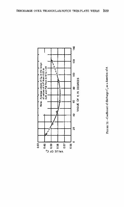
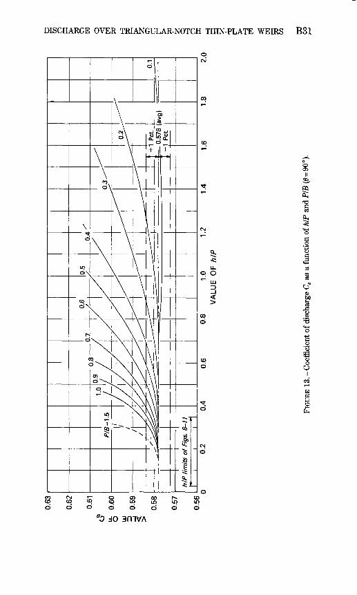
12. Coefficient of discharge Ce as a function of v ___________ 2913. Coefficient of discharge Ce as a function of h/P and P/B (v = 90 °) ___ 31
14-19. Comparisons of formulas for:14. 90°-notch weir ________________________ 3315. Notch angles of approximately 120° ______ 3416. Notch angles of approximately 60° _____ 3517. Notch angles of approximately 45° __________ 3618. Notch angles of approximately 27° ______ 3719. Notch angles of approximately 10° _________ 38
20. Effect of using h instead of he in equation 6 ____________ 43
TABLES
TABLE 1. Scope of Greve's experiments ______________ Bll2. Scope of Lenz's experiments with water ____________ 123. Values ofN and a for equation 16 (Lenz) ______ 13
CONVERSION FACTORS
The inch-pound system of units is used throughout this report. The following factors may be used to convert inch-pound units to International System of Units (SI):
Multiply inch-pound units By
ft (feet) in (inch)
ft2 (square feet)
Length0.30480
25.4
Area 0.09290
To obtain SI units
m (meters)mm (millimeters)
m2 (square meters)
CONTENTS VII
Multiply inch-pound units By To obtain SI units
Volume ft3 (cubic feet) 0.02832 m3 (cubic meters)
Temperature °F (degrees Fahrenheit) 5/9 (°F-32) °C (degrees Celsius)
SYMBOLS
a exponent in equation 16b width of rectangular notchB width of approach channelC coefficient of dischargeCe coefficient of discharge (based on effective head)E relative errorg acceleration due to gravityh piezometric head referred to vertex of notchhe effective headj exponent in equation 9h adjustment quantityhh head-adjustment quantityL a lengthM coefficient in equation 12m exponent in equation 12N coefficient in equation 16n exponent in equation 12P height of weir notch above bottom of channelQ dischargeR Reynolds numberS slope of sides of notchW Weber number7 specific weight6 included angle between sides of notchH dynamic viscosityp densitya surface tension

STUDIES OF FLOW OF WATER OVER WEIRS AND DAMS
DISCHARGE CHARACTERISTICS OF TRIANGULAR-NOTCH THIN-PLATE WEIRS
By JOHN SHEN
ABSTRACT
The triangular-notch, thin-plate weir is a convenient, inexpensive, and relatively precise flow-measuring instrument. It is frequently used to measure the flow of water in laboratories and in small, natural streams. This report includes an extensive review of the literature and presents a comprehensive analysis of the discharge characteristics of triangular-notch weirs. Previously published data are analyzed in the light of the effective-head concept, and a new discharge formula is proposed. Coefficients are recom mended and requirements for precise measurements are described. Limits of applicabili ty are discussed.
INTRODUCTION
The triangular-notch,thin-plate weir is used widely for measuring the flow of liquids in flumes and open channels. Simple in design and easily made from readily available materials, it is inexpensive, convenient to use, and easy to maintain. In permanent or portable form it is frequent ly used to measure the flow of water in laboratories and in small, natural streams. When several forms of weirs or flumes might be used, the triangular-notch weir is often preferred because of its greater ac curacy at low flows or its lesser sensitivity to approach-channel geometry and velocity distribution. Within the range of conditions for which verification data are adequate, and with reasonable care in its construction, installation, and use, the triangular-notch, thin-plate weir is a relatively precise instrument.
The triangular-notch weir has been the subject of considerable ex perimental research and published discussion. Unfortunately, however, most of the laboratory investigations have been restricted to a narrow range of notch angles and channel geometries. The 90°-notch weir has been most extensively studied. With few exceptions, water has been the liquid used in laboratory tests.
A large number of empirical discharge formulas have been proposed for triangular-notch weirs. Most of these were designed to fit a par-
Bl
B2 FLOW OF WATER OVER WEIRS AND DAMS
ticular set of experimental data. None provides a comprehensive solu tion, even for a single liquid. Deficiencies in these formulas are con cealed with numerous limits of applicability which greatly restrict their usefulness.
This report presents a comprehensive analysis of the discharge characteristics of triangular-notch, thin-plated weirs. Previously published data from various sources have been reanalyzed, and some of the traditional discharge formulas are compared with an original solu tion. The report is based on one of a series of studies of weirs and spillways which was undertaken by the U.S. Geological Survey under the direction of C. E. Kindsvater. Previously published reports in the series are concerned with broad-crested weirs (Tracy, 1957), rec tangular, thin-plate weirs (Kindsvater and Carter, 1959), and embankment-shaped weirs (Kindsvater, 1964). Portions of this report are adapted from unpublished reports and drafts of weir standards prepared by C. E. Kindsvater.
DESCRIPTION OF THE WEIR
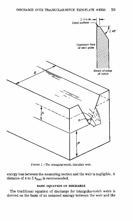
The weir which is the subject of this study is a symmetrical, V-shaped notch in a vertical thin plate. The line which bisects the angle of the notch is vertical and equidistant from the sides of the approach chan nel. The weir plate is smooth, plane, and perpendicular to the sides as well as the bottom of the approach channel. Figure 1 shows a triangular-notch, thin-plate weir installed at the end of a rectangular channel.
The crest surfaces of the weir notch are plane surfaces which form sharp, right-angle corners at their intersection with the upstream face of the weir plate. The width of the crest surface varies, but it is general ly between 1/32 and 1/16 inch. If the weir plate is thicker than 1/16 inch, the downstream edges of the notch are chamfered to make an angle of not less than 45° with the surface of the crest. Ideally, the channel upstream from the weir is straight, smooth, horizontal, rec tangular, and of sufficient length to develop the normal (uniform flow) turbulence and velocity distribution for all discharges. Usually, however, it is less than ideal, and baffles or screens are provided in order to simulate a normal velocity distribution. Channel and tailwater conditions downstream from the weir are such as to permit a free, fully ventilated flow from the notch. Provisions for ventilation ensure that pressure on the nappe surfaces is atmospheric. The tailwater is low enough that it does not interfere with the ventilation of the nappe or free flow from the notch.
The head on the weir is the measured vertical distance from the water surface to the vertex of the notch. The head-measuring section is located a sufficient distance upstream from the weir to avoid the region of surface draw-down, and it is sufficiently close to the weir that the
DISCHARGE OVER TRIANGULAR-NOTCH THIN-PLATE WEIRS B3
Upstream face of weir plate
^45°
FIGURE l.-The triangular-notch, thin-plate weir.
energy loss between the measuring section and the weir is negligible. A distance of 4 to 5 h is recommended.
BASIC EQUATION OF DISCHARGE
The traditional equation of discharge for triangular-notch weirs is derived on the basis of an assumed analogy between the weir and the
B4 FLOW OF WATER OVER WEIRS AND DAMS
orifice. In the derivation, an approximate velocity equation is in tegrated over assumed area limits of the nappe in the plane of the weir. The result is an equation which is useful mainly because it is dimen- sionally correct and because it is used almost universally as the basis for the analysis of experimental data. It is used herein as the basic equation of discharge.
In its traditional form, the basic discharge equation is
Q=CV20 tan *60 (1) lo £
in which Q is the volume rate of flow or discharge in cubic feet per sec ond; C is the nondimensional coefficient of discharge; g is the accelera tion due to gravity in feet per second per second; 0 is the angle included between the sides of the notch, usually measured in degrees; and h is the potentiometric head or height of the upstream liquid surface measured with respect to the vertex of the notch, in feet (in metric units, discharge would be stated in cubic meters per second, head in meters, and g in meters per second per second; C, being nondimen sional, would remain unchanged in numerical value).
Whereas C is assumed to be a coefficient of contraction in the tradi tional derivation, in actuality it is an experimentally determined coeffi cient which is dependent upon all the variables needed to describe the channel, the weir, and the discharging liquid. Thus, in the absence of a rigorous theoretical solution, dimensional relations must be used to guide the analysis of experimental data on triangular-notch weirs.
DIMENSIONAL ANALYSIS
The principal variables needed to define the discharge characteristics of a triangular-notch, thin-plate weir in a rectangular channel (fig. 1) are: Q, the discharge; B, the width of the approach channel; P, the height of the notch vertex with respect to the floor of the approach channel; h, the head on the weir, referred to the vertex of the notch; 6, the angle included between the sides of the notch; p, the density of the liquid; n, the viscosity of the liquid; a, the surface tension of the liquid; and 7, the specific weight of the liquid. If the discharge is selected as the dependent variable, a complete statement of the discharge function is
Q-f<jB,P,h>9t p 9 pt o,y). (2)
From this equation a nondimensional discharge ratio can be expressed as a function of five nondimensional ratios,
g
DISCHARGE OVER TRIANGULAR-NOTCH THIN-PLATE WEIRS B5
in which g=ylp. The dependent ratio in equation 3 is proportional to the coefficient of discharge. The first three ratios on the right-hand side describe the geometry of the weir, approach channel, and flow pattern; the last two ratios are the Reynolds number (R) and the Weber number (W).
SIGNIFICANCE OF THE RATIOS IN EQUATION 3
The first independent ratio in equation 3, h/P, is a measure of the depth-contraction characteristic. Because velocities in the channel upstream from the weir are proportional to the head, the h/P ratio, in combination with h/B and 0, is also a measure of the relative magnitude of the velocity in the approach channel.
The hIB ratio, in combination with 6, is a measure of the width- contraction characteristic (resembling bIB for rectangular-notch weirs; see Kindsvater and Carter, 1959). A more convenient ratio to serve the same purpose is P/B, which is the quotient of h/B divided by h/P. Thus, as a width-contraction ratio, P/B depends on h/P as well as 0.
The notch angle, 0, is a nondimensional measure of the shape of the weir notch. It is also a measure of the cross-sectional shape of the discharging liquid stream in the plane of the weir. In contrast with the discharge from most other forms of weirs, the shape of the stream from a triangular-notch weir is geometrically similar at all values of head, except as it is influenced by h/P and hIB.
The Reynolds number, R, is a measure of the relative influence of fluid viscosity. It is usually expressed as R = VLp//t, in which V is a typical velocity, L is a significant length, p is the mass density, and /A is the dynamic viscosity of the liquid. In this instance the head, h, is the dominant length parameter. As the velocity is also a function of h, the influence represented by the Reynolds number can be expressed in terms of h, p, and p.
The Weber number, W, is a measure of the relative influence of sur face tension. It is usually expressed as W = VVx/v/o/p in which a is the coefficient of surface tension of the liquid. As in the Reynolds number, h is the most significant length parameter for use in the Weber number. Because V is also a function of h, the influence represented by the Weber number can be expressed in terms of h, a, and p.
COEFFICIENT OF DISCHARGE FOR ONE LIQUID
In equation 3 the dependent variable is proportional to the coefficient of discharge. The independent variables include three geometric ratios and two fluid-property ratios. As explained in the preceding section, one of the geometric ratios, hIB, can be replaced with P/B, which is more convenient because it is a constant for a given weir installation.
B6 FLOW OF WATER OVER WEIRS AND DAMS
For one liquid over a limited temperature range, /A, a, and p can be assumed to be constants. Under these circumstances, the effects of viscosity and surface tension are related to the absolute magnitude of h alone. Thus, both R and W in equation 3 can be replaced with the quan tity h. It follows that, for one liquid and a limited range of temperatures,
(4)
In this report the only liquid of interest is water at normal atmospheric temperatures.
MODIFIED EQUATIONS FOR ONE LIQUID
The separate quantity h in equation 4 represents the combined and inseparable effects of viscosity and surface tension on the coefficient of discharge. The principal effects of viscosity are those which are associated with flow pattern modifications due to boundary resistance and separation. The principal effects of surface tension are associated with the curvature of the nappe and "clinging" on the crest surfaces of the notch. A detailed discussion of these effects is contained in the paper by Kindsvater and Carter (1959) on rectangular, thin-plate weirs. The following pertinent conclusions are drawn from that paper:
1. The combined effects of viscosity and surface tension on a notch weir are commensurate with fictitious increases in head and notch width.
2. The coefficient of discharge can be expressed in terms of the geometric ratios alone if the effects of viscosity and surface tension are accounted for by an adjustment of the measured values of head and notch width (for triangular-notch weirs, for which notch width is a function of h, only the measured values of head need be adjusted.)
3. The adjustment of measured values of h can be accomplished very simply, as indicated by the equation
he = h+kh, (5)
in which he is the effective (adjusted) head, h is the measured head, and kfr is a quantity which must be determined by experiment. 1
4. Use of the effective head, he, in place of h, results in the following modifications of equations 1 and 4 for one liquid:
1 Subsequent to the initial exposition of the "effective-head concept" by Kindsvater in 1956, it was applied successful ly to several kinds of weirs by others (Carter, 1956; Schlag, 1962a; Schlag, 1962b; John Shen, written commun., 1962; Burgess and White, 1966, among others).
DISCHARGE OVER TRIANGULAR-NOTCH THIN-PLATE WEIRS B7
W (6)
and
Equation 6, in combination with experimentally derived values of Ce and kh, is proposed as a new, comprehensive discharge formula for tri angular-notch, thin-plate weirs.2 Equation 7 defines Ce as a function of geometry alone; i.e., independent of fluid-property effects represented by h. The adequacy and validity of these equations must be examined in the light of experimental data. The data used for this purpose have been abstracted from the literature.
REVIEW OF THE LITERATURE
THOMSON'S EXPERIMENTS
James Thomson, Professor of Civil Engineering at Queen's College, Belfast, Ireland, was among the earliest experimental investigators of the triangular-notch weir (Thomson, 1858, 1861). Thomson's ex periments were made at a pond in an open field near Belfast. His pur pose in making the tests was to acquire experimental evidence to sup port his proposal that triangular-notch weirs be used instead of rec tangular weirs when the range of discharges to be measured included very small flows.
Professor Thomson's experimental equipment was crude by modern standards, and the range of conditions covered by his experiments was small. Nevertheless, some of his conclusions are pertinent here. Two notch angles, 90° and 127°, were investigated. For the 90° notch, Thomson recommended a constant value of C (eq 1) = 0.593. For the 127° notch, he recommended C- 0.617. Experiments made with the vertex of the notch at the level of the channel (P=0), with the channel wide enough to provide negligible approach velocities, showed no ap preciable influence which could be attributed directly to the value of P. With reference to the 127° notch, Thomson noted an instability which he associated with the nappe's tendency to cling to the upper portions of the wetted crest surfaces. This led him to recommend for larger discharges that two or more 90° notches (located side-by-side) be used instead of a single, large-angle notch.
2 Equation 6 is described as the Kindsvater-Shen equation in the international standard (International Standards Organization, 1975) which was based in part on the 1960 draft of this report.
B8 FLOW OF WATER OVER WEIRS AND DAMS
BARR'S EXPERIMENTS
One of the most extensive among the early investigations began as an effort to check Thomson's conclusions (Barr, 1910). James Barr, then a Carnegie Research Scholar at Glasgow University, Scotland, performed his experiments in the James Watt Engineering Laboratories. Many of the traditional formulas for 90°-notch weirs are based on the results of Barr's experiments. Because his instrumenta tion and technique were good, his data are among those selected for analysis in this report.
Barr's experiments were performed primarily with three different 90° notches. One weir was made of brass and two of iron plate. The upstream edges of the crest surfaces were square and sharp, and the width of the crest surfaces varied from 1/16 inch to 1/12 inch. A 54° notch was also tested. The weirs were placed at the end of a channel which was 4 feet wide and 22 feet long. The vertex of the notches was about 2 feet above the floor of the approach channel for most of Barr's tests.
To investigate the effect of channel width and weir height, Barr used false walls and floors in the approach channel. The false walls extended 3 feet upstream, and the floor extended 3.5 feet upstream from the weir plate. Tests were also made to investigate the effects of roughness and projections on the upstream face of the weir. For this purpose, roughness was produced with a mixture of varnish and emery particles. Projections consisted of narrow metal strips which were bolted to the weir bulkhead.
On the basis of his experiments, Barr disagreed with Thomson's con clusion that the coefficient of discharge was a constant. His results in dicated that the coefficient varied with the head. He concluded that the coefficient was increased by roughness and projections on the upstream face of the weir. He also concluded that the coefficient was independent of channel width if the width was at least eight times the head. For channel widths less than Sh, the coefficient increased as the width decreased. He also found that the coefficient decreased slightly with decreasing values of P when P was less than Kh, where K is a coefficient equal in value to the head in inches.
BARR-STRICKLAND FORMULA
A widely quoted formula for 90°-notch weirs was derived by T. P. Strickland (1910) on the basis of Barr's experiments. As an equation for C, the Barr-Strickland formula is
C= 0.566+^^- (8)
DISCHARGE OVER TRIANGULAR-NOTCH THIN-PLATE WEIRS B9
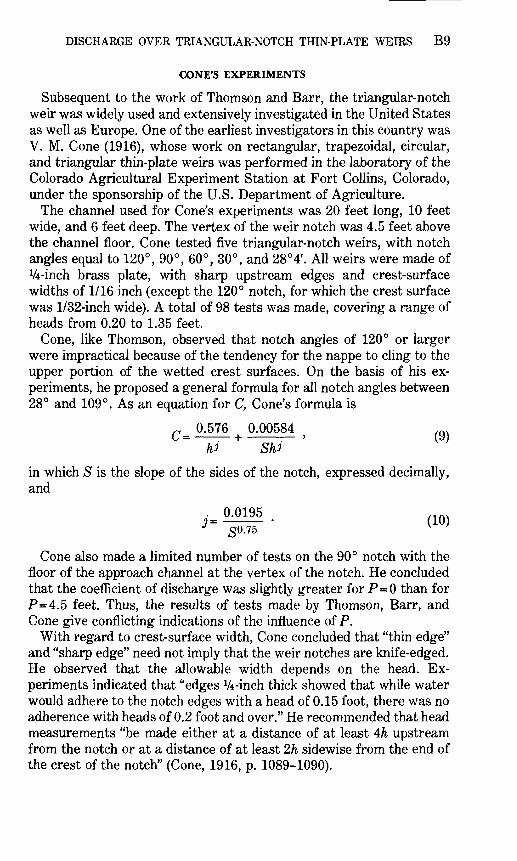
CONE'S EXPERIMENTS
Subsequent to the work of Thomson and Barr, the triangular-notch weir was widely used and extensively investigated in the United States as well as Europe. One of the earliest investigators in this country was V. M. Cone (1916), whose work on rectangular, trapezoidal, circular, and triangular thin-plate weirs was performed in the laboratory of the Colorado Agricultural Experiment Station at Fort Collins, Colorado, under the sponsorship of the U.S. Department of Agriculture.
The channel used for Cone's experiments was 20 feet long, 10 feet wide, and 6 feet deep. The vertex of the weir notch was 4.5 feet above the channel floor. Cone tested five triangular-notch weirs, with notch angles equal to 120°, 90°, 60°, 30°, and 28°4'. All weirs were made of V4-inch brass plate, with sharp upstream edges and crest-surface widths of 1/16 inch (except the 120° notch, for which the crest surface was 1/32-inch wide). A total of 98 tests was made, covering a range of heads from 0.20 to 1.35 feet.
Cone, like Thomson, observed that notch angles of 120° or larger were impractical because of the tendency for the nappe to cling to the upper portion of the wetted crest surfaces. On the basis of his ex periments, he proposed a general formula for all notch angles between 28° and 109°. As an equation for C, Cone's formula is
r 0.576 0.00584 ,Q. u = + ' (y )
in which S is the slope of the sides of the notch, expressed decimally, and
50.75
Cone also made a limited number of tests on the 90° notch with the floor of the approach channel at the vertex of the notch. He concluded that the coefficient of discharge was slightly greater for P=0 than for P=4.5 feet. Thus, the results of tests made by Thomson, Barr, and Cone give conflicting indications of the influence of P.
With regard to crest-surface width, Cone concluded that "thin edge" and "sharp edge" need not imply that the weir notches are knife-edged. He observed that the allowable width depends on the head. Ex periments indicated that "edges V4-inch thick showed that while water would adhere to the notch edges with a head of 0.15 foot, there was no adherence with heads of 0.2 foot and over." He recommended that head measurements "be made either at a distance of at least 4/& upstream from the notch or at a distance of at least 2h sidewise from the end of the crest of the notch" (Cone, 1916, p. 1089-1090).
BIO FLOW OF WATER OVER WEIRS AND DAMS
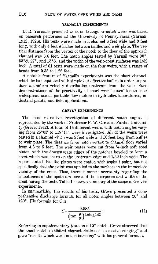
YARNALL'S EXPERIMENTS
D. R. Yarnall's principal work on triangular-notch weirs was based on research performed at the University of Pennsylvania (Yarnall, 1912, 1926). His tests were made in a channel 6 feet wide and 9 feet long, with only 4 feet 8 inches between baffles and weir plate. The ver tical distance from the vertex of the notch to the floor of the approach channel was 3.6 feet. The notch angles tested by Yarnall were 90°, 53°8', 27°, and 13°8', and the width of the weir-crest surfaces was 1/32 inch. A total of 61 tests were made on the four weirs, with a range of heads from 0.35 to 1.26 feet.
A notable feature of Yarnall's experiments was the short channel, which he had equipped with simple but effective baffles in order to pro duce a uniform velocity distribution upstream from the weir. Such demonstrations of the practicality of short weir "boxes" led to their widespread use as portable flow-meters in hydraulics laboratories, in dustrial plants, and field applications.
GREVE'S EXPERIMENTS
The most extensive investigation of different notch angles is represented by the work of Professor F. W. Greve at Purdue Universi ty (Greve, 1932). A total of 16 different weirs, with notch angles vary ing from 25°03' to 118°11', were investigated. All of the weirs were tested in a channel which was 5 feet wide and 16 feet long from baffles to weir plate. The distance from notch vertex to channel floor varied from 4.5 to 5 feet. The weir plates were cut from 3/s-inch soft steel plates, with the downstream edges of the notches beveled to form a crest which was sharp on the upstream edge and 1/32-inch wide. The report stated that the plates were coated with asphalt paint, but not specifically that the paint was applied to the surfaces in the immediate vicinity of the crest. Thus, there is some uncertainty regarding the smoothness of the upstream face and the sharpness and width of the crest during the tests. Table 1 shows a summary of the scope of Greve's experiments.
In summarizing the results of his tests, Greve presented a com prehensive discharge formula for all notch angles between 20° and 120°. His formula for C is
C= (11) (tan |)0.004^0.03
Referring to supplementary tests on a 10° notch, Greve observed that the small notch exhibited characteristics of "excessive clinging" and gave "results which were not in harmony" with his general formula.
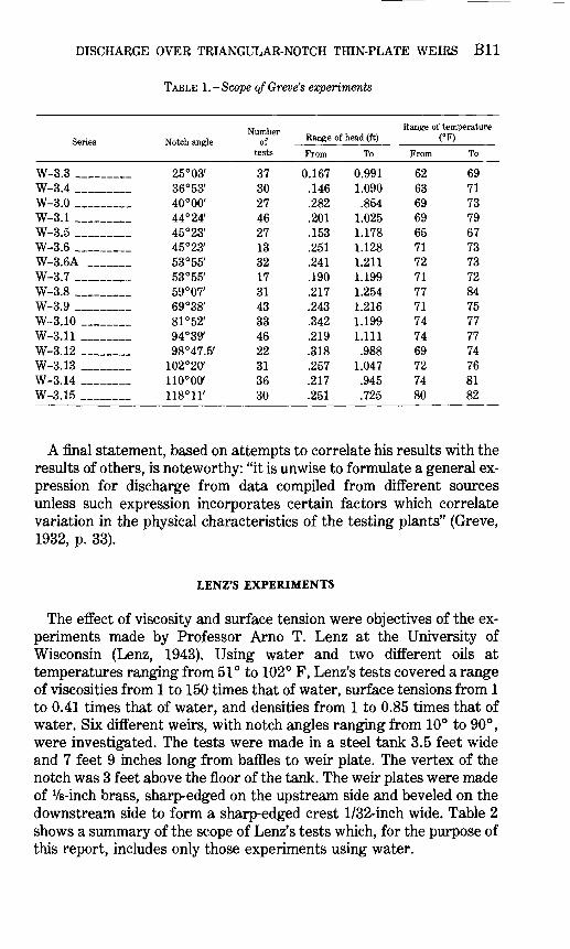
DISCHARGE OVER TRIANGULAR-NOTCH THIN-PLATE WEIRS Bll
TABLE 1.-Scope ofGreve's experiments
Series
W-3.3W-3.4 ______ W-3.0W-3.1W-3.5W-3.6W-3.6A _____ W-3.7W-3.8 _W-3.9 ______ W-3.10 ______ W-3.11 _______ W-3.12W-3.13W-3.14W-3.15
Notch angle
25°03' 36°53' 40°00' 44° 24' 45°23' 45°23' 53° 55' 53°55' 59°07' 69°38' 81° 52' 94°39' 98°47.5'
102°2(y 110°00' 118°H'
Number of
tests
37 30 27 46 27 13 32 17 31 43 33 46 22 31 36 30
Range of head (ft)
From
0.167 .146 .282 .201 .153 .251 .241 .190 .217 .243 .342 .219 .318 .257 .217 .251
To
0.991 1.090
.854 1.025 1.178 1.128 1.211 1.199 1.254 1.216 1.199 1.111
.988 1.047 .945 .725
Range of temperature (°F)
From
62 63 69 69 65 71 72 71 77 71 74 74 69 72 74 80
To
69 71 73 79 67 73 73 72 84 75 77 77 74 76 81 82
A final statement, based on attempts to correlate his results with the results of others, is noteworthy: "it is unwise to formulate a general ex pression for discharge from data compiled from different sources unless such expression incorporates certain factors which correlate variation in the physical characteristics of the testing plants" (Greve, 1932, p. 33).
LENZ'S EXPERIMENTS
The effect of viscosity and surface tension were objectives of the ex periments made by Professor Arno T. Lenz at the University of Wisconsin (Lenz, 1943). Using water and two different oils at temperatures ranging from 51° to 102° F, Lenz's tests covered a range of viscosities from 1 to 150 times that of water, surface tensions from 1 to 0.41 times that of water, and densities from 1 to 0.85 times that of water. Six different weirs, with notch angles ranging from 10° to 90°, were investigated. The tests were made in a steel tank 3.5 feet wide and 7 feet 9 inches long from baffles to weir plate. The vertex of the notch was 3 feet above the floor of the tank. The weir plates were made of Vs-inch brass, sharp-edged on the upstream side and beveled on the downstream side to form a sharp-edged crest 1/32-inch wide. Table 2 shows a summary of the scope of Lenz's tests which, for the purpose of this report, includes only those experiments using water.
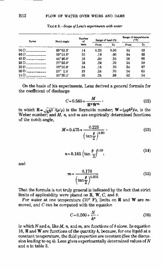
B12 FLOW OF WATER OVER WEIRS AND DAMS
TABLE 2. -Scope ofLenz's experiments with water
Series
90 D_ _ __60D_ _ __45D __ _ _28D _20 D_ _ __20 D _ __10 D __ _ _
Notch angle
89°53.2; 59°51.0' 44°40.0' 27°55.0' l$°55.ff 20° 2.5' 10°20.1'
Number of
tests
14 33 18 18 24 19 33
Range of head (ft)
From
0.23 .16 .20 .26 .18 .24 .24
To
0.50 .60 .55 .70 .70 .70 .88
Range of temperatures
From
61 54 56 51 54 54 52
To
63 62 60 59 67 65 54
On the basis of his experiments, Lenz derived a general formula for the coefficient of discharge
M C=0.560+ ' (12)
in which R= N/g^3 /Gi/p) is the Reynolds number; W=(pgh2)/a, is the Weber number; and M, n, and m are empirically determined functions of the notch angle,
M=0.475+ °'225 > (13)- \0.80
/ 0 \0-09 (14)n~ 0.165 (tan -^ ,
and
« 0.170 ,1(.vm- (15)- ' 0.035
That the formula is not truly general is indicated by the fact that strict limits of applicability were placed on R, W, C, and 6.
For water at one temperature (70° F), limits on R and W are re moved, and C can be computed with the equation
C=0.560+ > (16) ha
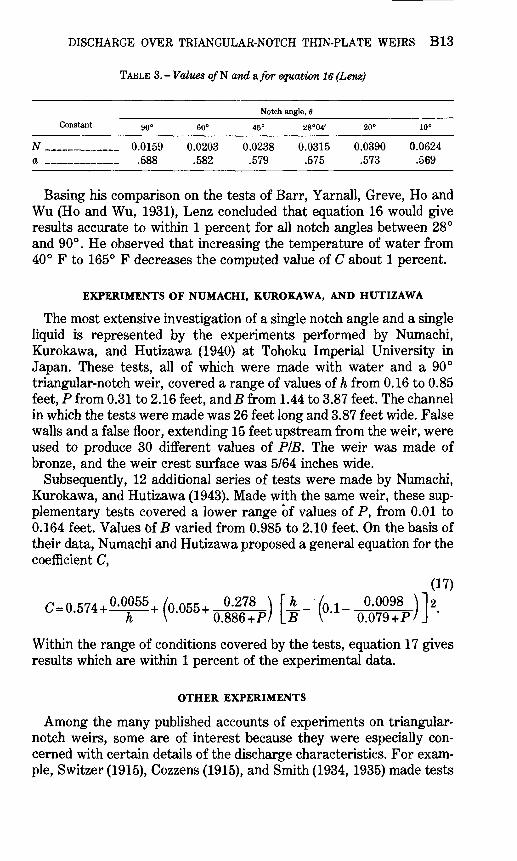
in which AT and a, like M, n, and m, are functions of 0 alone. In equation 16, R and W are functions of the quantity h, because, for one liquid at a constant temperature, the fluid properties are constant (See the discus sion leading to eq 4). Lenz gives experimentally determined values of AT and a in table 3.
DISCHARGE OVER TRIANGULAR-NOTCH THIN-PLATE WEIRS B13
TABLE 3. - Values o/N and a/or equation 16 (Lenz)
Notch angle, 9
Constant
N __a _
90°
. 0.0159.588
60°
0.0203.582
45°
0.0238.579
28°04'
0.0315.575
20°
0.0390.573
10°
0.0624.569
Basing his comparison on the tests of Barr, Yarnall, Greve, Ho and Wu (Ho and Wu, 1931), Lenz concluded that equation 16 would give results accurate to within 1 percent for all notch angles between 28° and 90°. He observed that increasing the temperature of water from 40° F to 165° F decreases the computed value of C about 1 percent.
EXPERIMENTS OF NUMACHI, KUROKAWA, AND HUTIZAWA
The most extensive investigation of a single notch angle and a single liquid is represented by the experiments performed by Numachi, Kurokawa, and Hutizawa (1940) at Tohoku Imperial University in Japan. These tests, all of which were made with water and a 90° triangular-notch weir, covered a range of values of h from 0.16 to 0.85 feet, P from 0.31 to 2.16 feet, and B from 1.44 to 3.87 feet. The channel in which the tests were made was 26 feet long and 3.87 feet wide. False walls and a false floor, extending 15 feet upstream from the weir, were used to produce 30 different values of PIE. The weir was made of bronze, and the weir crest surface was 5/64 inches wide.
Subsequently, 12 additional series of tests were made by Numachi, Kurokawa, and Hutizawa (1943). Made with the same weir, these sup plementary tests covered a lower range of values of P, from 0.01 to 0.164 feet. Values Of B varied from 0.985 to 2.10 feet. On the basis of their data, Numachi and Hutizawa proposed a general equation for the coefficient C,
(17)
0=0.574^(0.055.^) £- (M-
Within the range of conditions covered by the tests, equation 17 gives results which are within 1 percent of the experimental data.
OTHER EXPERIMENTS
Among the many published accounts of experiments on triangular- notch weirs, some are of interest because they were especially con cerned with certain details of the discharge characteristics. For exam ple, Switzer (1915), Cozzens (1915), and Smith (1934, 1935) made tests
B14 FLOW OF WATER OVER WEIRS AND DAMS
to determine the influence of temperature on the discharge of water. On the basis of tests on 90° and 54° notches, with temperatures rang ing from 39° F to 165° F, Switzer concluded that the effect on the coefficient of discharge was less than 2 percent and "inappreciable com pared with other factors present". Cozzens, on the other hand, presented a curve to be used to make a small correction over a range of temperatures from 60° F to 220° F. Smith developed an empirical for mula which incorporated the kinematic viscosity in a correction coeffi cient.
Professor H. W. King (1916, 1954) made tests on 90°, 60°, and 22.5° notches at the University of Michigan. His weirs were made of steel, with a sharp upstream crest edge and a crest-surface width of Vs inch. The vertex of the notch was 2 feet above the floor of the experimental channel. On the basis of his experiments, Professor King developed the following formulas:
(90° notch) C--' (18)
(60° notch) C= 0.595 ft0 - 01 , (19)
(22.5° notch) C=9L, (20)
An investigation performed at Cornell University by Ho and Wu (1931) is notable for the large range of heads (from 0.129 to 3.43) covered by the tests. All of these tests were made in a channel 6 feet wide, 12 feet deep, and 30 feet long from baffles to weir plate. Weirs tested included notch angles of 90°, 60°, 37°, 28°, and 19°. The ver tices of notches were a minimum distance of 8 feet above the channel floor. The weir plates were made of galvanized sheet metal or brass, with sharp, square, upstream edges. Lenz (1943) observed that his general formula for water (eq 16) was confirmed within 1 percent by the Ho and Wu data.
From 1931 to 1934, four investigations were made at Princeton University by senior students under the direction of Professor L. F. Moody. Most pertinent of these is the investigation by Allerton (1932), which involved tests with notch angles of 90°, 60°, 54°, and 30°. Of particular interest is the fact that Allerton analyzed his data on the basis of a formula which involved a head adjustment similar to that used in equation 5. The formula was attributed to Moody, but no men tion of the formula is made in reports of two subsequent investigations made at Princeton.
Investigations which placed emphasis on the influence of viscosity were made by Mawson (1927), Thornton (1929), and Smith (1934, 1935). Because they ignored the equal or larger influence of surface tension, however, the results of the studies were inconclusive.
DISCHARGE OVER TRIANGULAR-NOTCH THIN-PLATE WEIRS B15
Hertzler (1938) was especially concerned with 120° notches. On the basis of his tests on six different weirs, all with 6 = 120°, he proposed the formula
SUMMARY
Published accounts of experimental investigations agree on very few details of the discharge characteristics of triangular-notch weirs. Some of the disagreements are doubtless the result of differences in equip ment and technique. More significantly, however, conclusions drawn from the experiments are believed to differ because of certain inade quacies in traditional methods of analyzing the data.
It is reasonable to assume that experimental equipment was ade quate and that the work was done with skill and care. Nevertheless, there are indications that some of the weirs were neither sharp-edged, thin-crested, nor smooth-faced. Crude equipment and technique in other instances resulted in systematic errors related to the measure ment of Q, h, and 6. The effect of these deviations cannot be determined from the information available.
There is some agreement that weirs with notch angles less than about 20° or greater than about 100° exhibit characteristics of in stability which are related to the intermittent clinging of the nappe to the surface of the crest. Similar behavior was observed at extremely low heads on all notch angles.
Most investigators found that C varied with notch angle. This is a clear indication of a shortcoming in the traditional, so-called theoretical equation of discharge (eq 1). Only one of the many investigations (by F. Numachi and others) included a systematic study of the influence of weir placement and channel geometry. However, this study was made with only one notch angle and one liquid. Several investigators demonstrated the practicality of using short approach channels if they are effectively equipped with baffles. No comprehensive studies have been made of the influence of velocity distribution and turbulence in the approach channel.
Few investigators attempted to isolate and evaluate the influence of the physical properties of the liquid, although several attempted to determine the effect of temperature on the discharge of one liquid (water). Their conclusions are remarkable for their disagreement. Lenz made considerable progress in isolating the separate effects of viscosity and surface tension, but the range of conditions covered in the in vestigation was quite limited. For this reason, his proposed general for mulas are restricted in applicability. They are also inconvenient to use.
B16 FLOW OF WATER OVER WEIRS AND DAMS
Most investigators working with water at normal temperatures reported a correlation between C and h. Empirical formulas were evolved to account for this correlation, but no explicit recognition was given to the fact that the h correlation is evidence of the combined effects of viscosity and surface tension. Thus, the "scale effect" implica tions of the phenomenon were ignored. It is believed that the effective- head concept (eq 5) provides a reasonable and practical method of ac counting for the effects related to the absolute magnitude of h.
No additional experiments were made for this investigation. Instead, experimental data obtained from some of the sources reviewed above are used in the following analysis.
ANALYSIS OF DATA
EVALUATION OF kh
The coefficient Ce in equations 6 and 7 is described as a function of geometric ratios (hIP, PIE, and 6) when he , the "effective head," is deter mined from equation 5,
he =h+kh. (5)
In this equation, h is the measured head on the notch and k^ is an ex perimentally determined quantity that accounts for the combined effects of viscosity and surface tension. Comparison of equations 4 and 7 shows that the effect of the effective-head adjustment is to relieve the coefficient of discharge of dependency on h. This criterion is used to determine the value of kh which is applicable to a specific set of ex perimental data. For one liquid over a small temperature range, and for one notch angle, k^ is assumed to be a constant.
The validity of the several basic assumptions related to the effective head concept has been demonstrated in a previous study of rectangular weirs. Nevertheless, the practicality of the concept as applied specifically to triangular-notch weirs must be established on the basis of experimental data for triangular-notch weirs. The results of ex periments by Barr, Cone, Yarnall, Greve, Lenz, and Numachi, Kurokawa, and Hutizawa are selected for this purpose. Because the flow of water at ordinary atmospheric temperatures is of principal in terest to the Geological Survey, and because data on other liquids are limited in many ways, the data used are only those which involve water in the temperature range from 40° F to 85° F.
In the validation process, the quantity k^ is evaluated from ex perimental data by a trial procedure. For a series of tests in which h is the principal variable, k^ is determined by successive approximations as the quantity which will remove the correlation between C and h. The
DISCHARGE OVER TRIANGULAR-NOTCH THIN-PLATE WEIRS B17
U.DJ
0.62
0.61
0.60
0.59
0.58
0.57
0.63
0.62
0.61
0.60
0.59
0.58
0.57
n RR
\
AA
*;
^ ^^
£--
a»
AL
^
A
A f
ir*- ~~^
C as a
A-
B Ce as
AA A
|A ^ 4
~x
functk
A x
a func
L_ _ _ _ x
>n of /j
-x -x. ~x Q
/P
zir
^eM^i-c
X
p=
-A
-X-A
>o^
EXPLANATION
Symbol Head, in feet
A O.K h <0.3
X 0.3< h <0.5 0 0.5< /? <0.7
Notes: fi=3.87 ft, */7=0.003 ft, P=0.64-2.16 ft
-x x
tion o:
.^x^
/7/P
T38^6^>^<X
r-o-^T
0.06 0.08 0.10 0.12 0.14 0.16 0.18 0.20 0.22 0.24 0.26 0.28 0.30 0.32
VALUE OF h/P
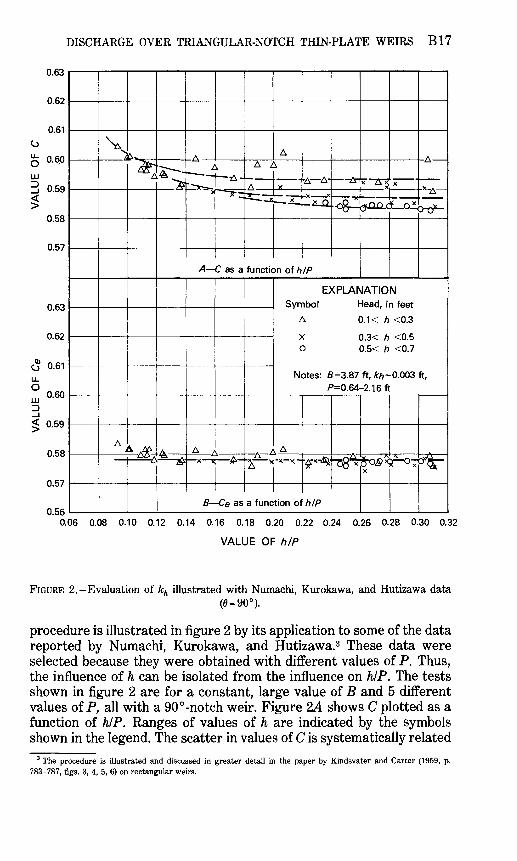
FIGURE 2.-Evaluation of kh illustrated with Numachi, Kurokawa, and Hutizawa data(0 = 90°).
procedure is illustrated in figure 2 by its application to some of the data reported by Numachi, Kurokawa, and Hutizawa.3 These data were selected because they were obtained with different values of P. Thus, the influence of h can be isolated from the influence on hIP. The tests shown in figure 2 are for a constant, large value of B and 5 different values of P, all with a 90°-notch weir. Figure 2A shows C plotted as a function of hIP. Ranges of values of h are indicated by the symbols shown in the legend. The scatter in values of C is systematically related
3 The procedure is illustrated and discussed in greater detail in the paper by Kindsvater and Carter (1959, p. 783-787, figs. 3, 4, 5, 6) on rectangular weirs.
B18 FLOW OF WATER OVER WEIRS AND DAMS
to the magnitude of h as shown by the dashed curves. There is no clear ly defined correlation with P. Figure 25 shows Ce plotted as a function of hIP. The value of k^ which was used in the computations of Ce for this figure was 0.003 foot. Evidence of the lack of correlation between Ce and h is shown by the fact that one curve drawn through all the points is horizontal, and the scatter is greatly reduced. Thus, the validity of the effective-head concept is demonstrated, and the value k^= 0.003 foot is shown to be appropriate for the tests by Numachi and others.
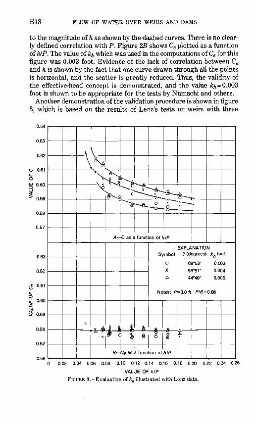
Another demonstration of the validation procedure is shown in figure 3, which is based on the results of Lenz's tests on weirs with three
0.64
0.63
0.62
0.61
0.60
0.59
0.58
0.57
0.63
0.62
0.61
0.60
0.59
0.58
0.57
0.56
-*-&-*
EXPLANATION Symbol 0 (degrees) k^ feet
0 89°53' 0.003
X 59°5V 0.004A 44°40' 0.005
Notes: P=3.0 ft, P/B=0.86
B Ce as a function of h/P
0 0.02 0.04 0.06 0.08 0.10 0.12 0.14 0.16 0.18 0.20 0.22 0.24 0.26
VALUE OF h/P FIGURE 3.-Evaluation of kh illustrated with Lenz data.
DISCHARGE OVER TRIANGULAR-NOTCH THIN-PLATE WEIRS B19
different notch angles. Values of the notch angles are shown in the legend. In the top part of figure 3, C is plotted as a function of hIP, but because P is constant for each weir, the separation and curvature of the lines drawn through the plotted points show the influence related to h and 6.
The lower part of figure 3 shows Ce plotted as a function of hIP for the Lenz data. In this instance, different values of k^ were derived for each value of 6, as shown in the legend. Here again the effectiveness of kh in eliminating h as an independent variable is demonstrated by the fact that curves drawn through the points are essentially horizontal. Coincidentally, a single curve fits the three sets of points reasonably well, showing that 6 has a minimal effect on Ce for notch angles be tween 45° and 90°. Values of PIB and h/P represented by the tests shown in figures 2 and 3 are in the range in which these variables also have negligible influence on Ce. This fact is demonstrated subsequently.
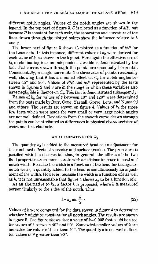
Values of k^ for values of 6 between 10° and 120° were determined from the tests made by Barr, Cone, Yarnall, Greve, Lenz, and Numachi and others. The results are shown on figure 4. Values of k^ for those few tests which were made for very small or very large notch angles are not well defined. Deviations from the smooth curve drawn through the points can be attributed to differences in physical characteristics of weirs and test channels.
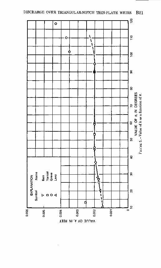
AN ALTERNATIVE FOR kh
The quantity k^ is added to the measured head as an adjustment for the combined effects of viscosity and surface tension. The procedure is justified with the observation that, in general, the effects of the two fluid properties are commensurate with a fictitious increase in head and notch width. Because the width is a function of the head for triangular- notch weirs, a quantity added to the head is simultaneously an adjust ment of the width. However, because the width is a function of 6 as well as h, it is not unreasonable that figure 4 shows k^ to be a function of 6.
As an alternative to k^, a factor k is proposed, where k is measured perpendicularly to the sides of the notch. Thus,
fc-Afcsin-!-- (22) z
Values of k were computed for the data shown in figure 4 to determine whether k might be constant for all notch angles. The results are shown in figure 5. The figure shows that a value of k= 0.002 foot could be used for values of 0 between 40° and 90°. Somewhat smaller values of k are indicated for values of 6 less than 40°. The quantity k is not well defined for values of 6 greater than 90°.
w CO o
0.02
4
50
60
70
80
VA
LUE
OF
0, I
N D
EGR
EES
FIG
URE
4. -
Val
ue o
f kh
as
a fu
nctio
n of
0.
9010
011
012
0
s o Sd so
DISCHARGE OVER TRIANGULAR-NOTCH THIN-PLATE WEIRS B21
» To <oE .- c > NCO 1= fc P C
31- -s
D O
8
w .in ^HI C4HDC °O C!ill O
O -«
UJ *0
i 3 < 13
lU3H 05
O
133d Nl '* dO 3mVA
B22 FLOW OF WATER OVER WEIRS AND DAMS
It is apparent that the effective head in the modified basic equation of discharge (eq 6) can be evaluated in terms of either k or k^. If k^ is used, values of k^ are read from figure 4. If k is used, values of k can be read from figure 5, or, in the range from 40° to 90°, he can be computed as
(23)sn
Which of these alternatives is the more convenient is conjectural. Hereafter in this report, he is computed with values of k^ from figure 4.
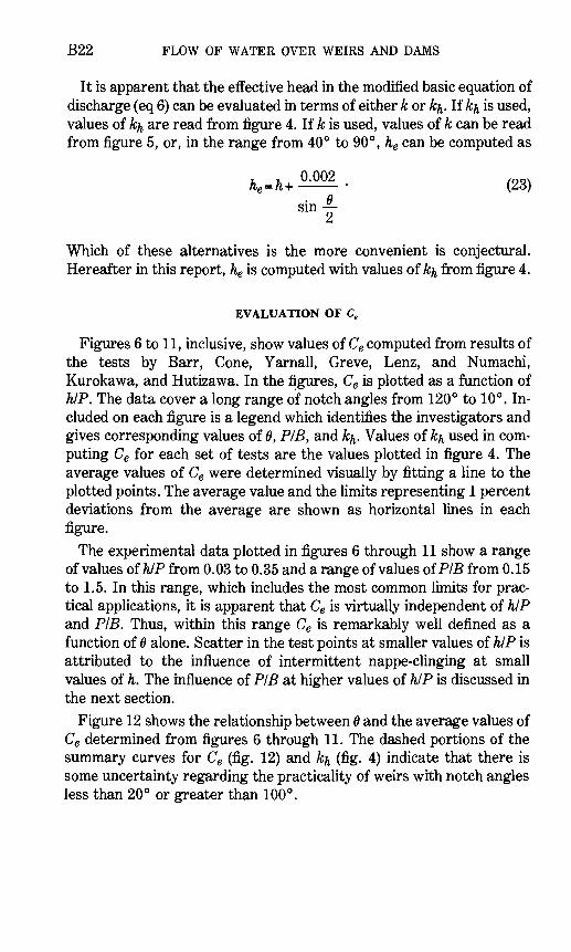
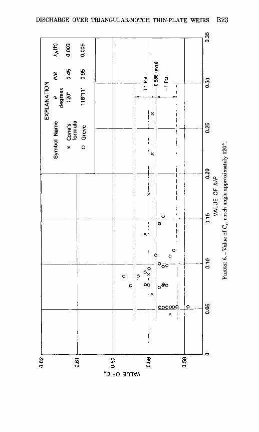
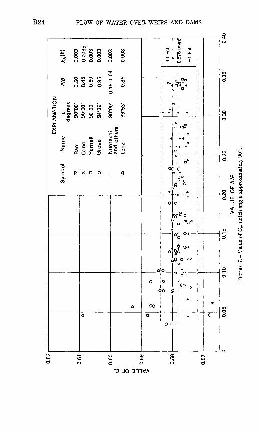
EVALUATION OF Ce
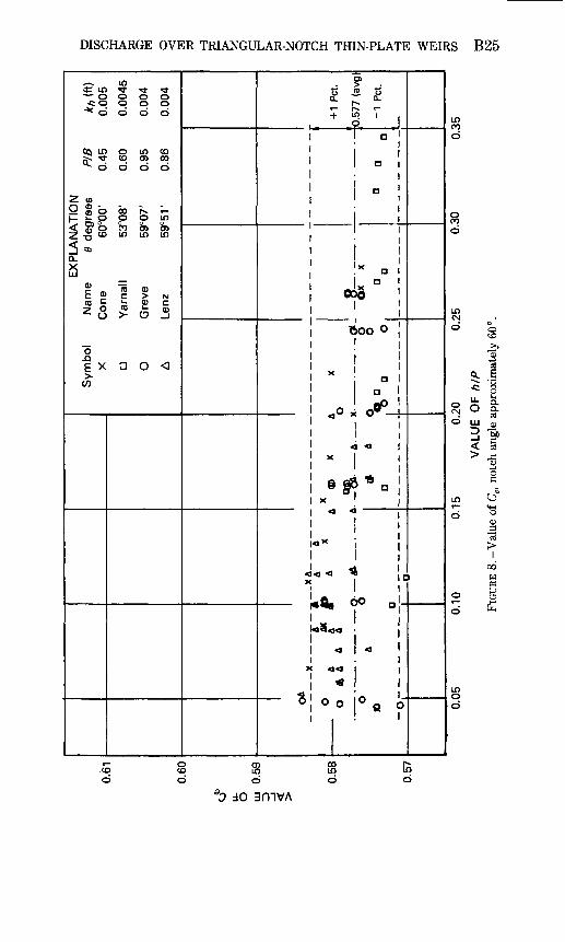
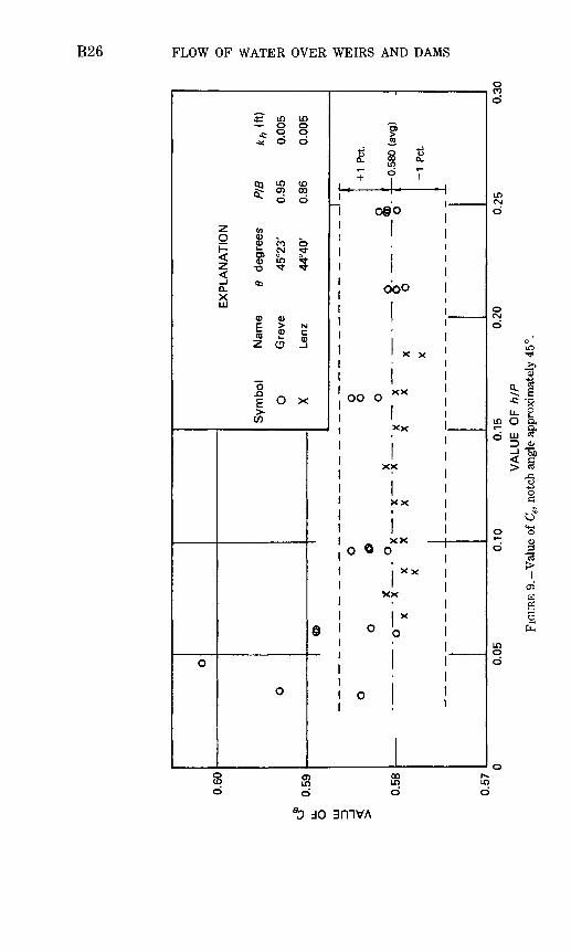
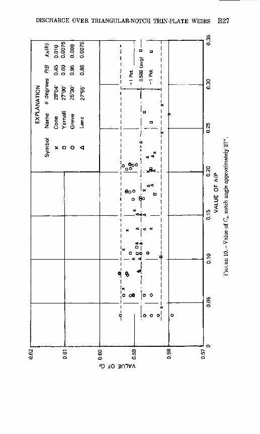
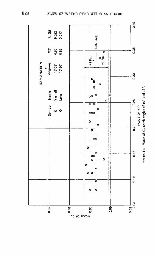
Figures 6 to 11, inclusive, show values of Ce computed from results of the tests by Barr, Cone, Yarnall, Greve, Lenz, and Numachi, Kurokawa, and Hutizawa. In the figures, Ce is plotted as a function of h/P. The data cover a long range of notch angles from 120° to 10°. In cluded on each figure is a legend which identifies the investigators and gives corresponding values of 6, P/B, and k^ Values of kh used in com puting Ce for each set of tests are the values plotted in figure 4. The average values of Ce were determined visually by fitting a line to the plotted points. The average value and the limits representing 1 percent deviations from the average are shown as horizontal lines in each figure.
The experimental data plotted in figures 6 through 11 show a range of values of h/P from 0.03 to 0.35 and a range of values of PIE from 0. 15 to 1.5. In this range, which includes the most common limits for prac tical applications, it is apparent that Ce is virtually independent of h/P and PIE. Thus, within this range Ce is remarkably well defined as a function of 6 alone. Scatter in the test points at smaller values of h/P is attributed to the influence of intermittent nappe-clinging at small values of h. The influence of PIE at higher values of hIP is discussed in the next section.
Figure 12 shows the relationship between 6 and the average values of Ce determined from figures 6 through 11. The dashed portions of the summary curves for Ce (fig. 12) and kh (fig. 4) indicate that there is some uncertainty regarding the practicality of weirs with notch angles less than 20° or greater than 100°.
0.62
0.61
o u_
0.60
O H
ID
t
0.59
0.58
X
o o
o
0
0 o
x
o-
X
X
o o
o o
O
<B>
O|
0
0
O1
81
O
^
1 0
o 0
0
EX
PLA
NA
TIO
N
Sym
bol
Nam
e 6
PIB
AT
, (ft)
de
gree
s X
C
one'
s 12
0°
0.45
0.
003
form
ula
O
Gre
ve
118°
11'
0.95
0.
005
XX
+ 1
-1
Pet.
.588
(av
g)
Pet.
0.05
0.
10
0.15
0.
20V
ALU
E O
F hI
P
FIGU
RE 6
.-V
alue
of C
e, no
tch
angl
e ap
prox
imat
ely
120°
.
0.25
0.30
CO O
0.35
a o K f w to oo
W
to
LL
O
0.62
0.61
0.60
0.59
0.58
0.57
o o
0 o
X o
o 8 °
0 o o
- Y
^X
7
7
O 0 1 <0
>07O
Q
O
I O
--X
-
O*B
>-
O-A
-0 1
L -
f !
* 2
QADa
a
EX
PLA
NA
TIO
N
Sym
bol
Nam
e 0
PIB
*y
,(ft)
de
gree
s
V
Bar
r 90
°00'
0.
50
0.00
3 x
Con
e 90
°00'
0.
45
0.00
35n
Yarn
all
90°0
0'
0.60
0.
003
0
Gre
ve
94°3
9'
0.95
0,
003
+
Num
ach
i 90
°00'
0.
16-1
.04
0.00
3 an
d oth
ers
A
Lenz
89
°53'
0.
86
0.00
3
4v
o +
*
;^,r
!7.t
f-r
4 ^r
7^
Q
-fD
I+1
Pet
.
- 0
.578
(av
g)
-1 P
et.
0.05
0.10
0.15
0.25
0.20
V
ALU
E O
F hI
P
FIGU
RE 7
.-V
alue
of
Ce, n
otch
ang
le a
ppro
xim
atel
y 90
c
0.30
0.35
0.40
DISCHARGE OVER TRIANGULAR-NOTCH THIN-PLATE WEIRS B25
Is ** o
Oq in
^ 0
O Q3 - _ <D 0
z-g §^ **>CL
UJ
E *(0 £z c
"onE Xto
o o o000o o o
S in co o oo
o o o
oo r^ J- o o ino o oCO O> O>in in in
^ (0 0) C > N^ (33 c
> (D ^
n o <l
c . i
+ L
1 S!
1
1
1
1
1
1
1
1
1
i^
I
1 «
1
1
! -iiI O ^.1 <\1! -1 a a?i § §F1 x1 < <\\
1 <« *X
1
1*^1 c11r **i <i
X 44
1 *
O | O o1
? .J £
^-
a
a
x aas
100 °
aaffj
t O -
i <i
i -ft1 a
-
'
Y/\
4
°Q 0-1
inCOo
oCO0
inCMo
oCMO
in
o
2o
in oo"
a. £< 'I
Ll- Q,O Pu
UJ (D
jo amvA
w to
0.60
0.59
0.58
0.57
O
o o
<n>
oo
oX
0
O
' X
" '
"X
X X
XK 'X
"X
X X
3
Sym
bol
Nam
e
O
Gre
ve
X Le
nz
O O 0
< X
< x
x X
EX
PLA
NA
TIO
N
6 de
gree
s
45°2
3'
44°4
0'
00
©£
°O
PIB
k
h (f
t)
0.9
5
0.0
05
0.8
6
0.0
05
-+
1 P
et.
- - -0
.580 (
avg)
-1
Pet.
0.05
0.
10
0.15
VA
LUE
OF
h/P
FI
GURE
9.-
Val
ue o
f Ce
, not
ch a
ngle
app
roxi
mat
ely
45°.
0.20
0.25
0.30
O
3 O ^ 1 O
O
DISCHARGE OVER TRIANGULAR-NOTCH THIN-PLATE WEIRS B27
If£ °£ coo * 0 0
QQ LO c
^ d ow
z £ * c2 8* g S=I- § S E5 w <N c\z *
^a. <D tx 1 S £m J° o « z o >
"5
E x c> w
to
; o o 0 0d d
LO CDO> COd d
> b LO) CO LO
LO ?^CM CN
i <D
3 i_ 0)- 0 -J
1 0 <
c'
2 iT- ej_
«
o °ooo ̂ *
e o0 5
X«a-
X *"
«3«a
XO OC
o <
< fc ^
x
o oO
o
1
3 - !5 1E 18 c in Q- |D t- '
1 1
1
1
1X
a 1 .1
a |i1
X1
3 1
1X |
4 ^ i 1
^ 5^ I
I
X** 1D 1*> !
i1-1 i
i
Ii i
i) 0 1
a1
11 1
O O |
1 -x
o o oj o
0
oCO0
LO CMO
OCMO
LO
0
0
o
LO0o
o
i£ .2O "houi i3 _e
O *^ oa>
13
COo 6
ao do
0.62
0.61
0.60
0.59
0.58
0.
O0
°
0 ^o
0
cb
0
o0
EX
PLA
N A
T 8 S
ymb
ol
Nam
e
degr
Q
Ya
rna
ll 13
°C
©
Lenz
10
°;
o o
a a
O
o <o>
o
a>
o
a
ON
ees
P/B
k
h (f
t)
)8'
0.60
0.
022
>0'
0.86
0.
017
+ 1
Pet.
o
a -1
Pet.
Q
05
0.10
0.
15
0.2
0
0.25
0.
30
0.59
7 (a
vg)
0.3
5
Q.i
VALU
E OF
hIP
FIG
URE
11.
-Val
ue o
f C
e, no
tch
angl
es o
f 10
° an
d 13
°.
DISCHARGE OVER TRIANGULAR-NOTCH THIN-PLATE WEIRS B29
T3 s
OO
IcjT I
aMg
B30 FLOW OF WATER OVER WEIRS AND DAMS
INFLUENCE OF h/P AND P/B
A few tests involving different values of P and B were made by Barr, and some tests withP=0 were reported by Thomson and Cone. Among the experimental data available to the writer, however, the only data covering an extensive range of values of hJP and PIE were those ob tained from the experiments on 90° notches made by Numachi, Kurokawa, and Hutizawa.
Values of Ce were computed from the results of the Numachi- Kurokawa-Hutizawa tests, using kh= 0.003 foot. Smooth curves inter polated from the plotted data were cross-plotted to obtain the family of curves showing Ce as a function of hIP and PIE on figure 13. The results are a comprehensive solution for 90° -notch weirs that, because of the degree of extrapolation from the data, must be regarded as unsubstan tiated. The h/P limit lines at the lower left corner of figure 13 illustrate the limited hIP range of the Numachi-Kurokawa-Hutizawa tests, and the Ce values from those tests, plotted in figure 7, are all within 1 per cent of the average value (0.578).
COMPARISON OF FORMULAS
BASIS OF COMPARISON
Derived from tests in which hIP and PIE were of negligible significance, the traditional formulas for triangular-notch weirs are generally of the form
C=/«U), (24)
in which an empirically derived term involving h accounts for the com bined effects of viscosity and surface tension for water at ordinary temperatures. Unfortunately, the significance of h was not understood by the originators of most of these formulas. Consequently, the more conservative investigators specified a range of applicability which was based on the limits of their test conditions.
In order to compare the proposed new formula (eq 6) with the classic formulas, values of C were computed from the classic formulas and from the equation,
_h+kh 2 -
obtained from the solution of equations 1 and 6.Values of Ce and kh were obtained from figures 10 and 4, respectively.
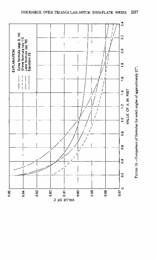
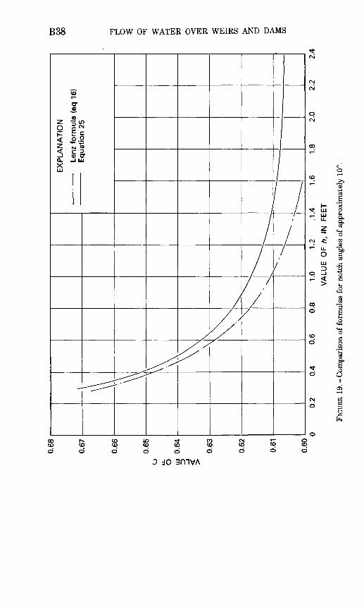
The comparisons are shown in figures 14-19, inclusive, in which C is shown as a function of h for selected values of 6.
DISCHARGE OVER TRIANGULAR-NOTCH THIN-PLATE WEIRS B31
&I
Io
I
8 S 56 c> o
oCOd d
dO 3niVA
B32 FLOW OF WATER OVER WEIRS AND DAMS
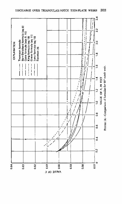
gO'-NOTCH WEIR
The most frequently used triangular-notch weir is one with a notch angle of 90° . Some of the classic formulas are intended for use with this weir alone. Figure 14 shows a comparison of values of C computed from the well-known formulas of Thomson, Barr-Strickland (eq 8), Cone (eq 9, 10), Greve (eq 11), Lenz (eq 16), and King (eq 18) and the formula determined from equation 25 in combination with figures 12 and 4. The Thomson "formula" is actually just C= 0.593, because Thom son did not propose a correlation with h.
It is emphasized that figure 14 is a comparison of formulas, whereas figure 7 is a comparison of the data from which the formulas were derived. Thus, the disagreement shown in figure 14, especially at small values of h, is to a large degree evidence of inadequacies of the for mulas as representations of the data on which they were based. Figure 7 shows that the source data for all the formulas agree remarkably well in defining Ce for use in equation 6.
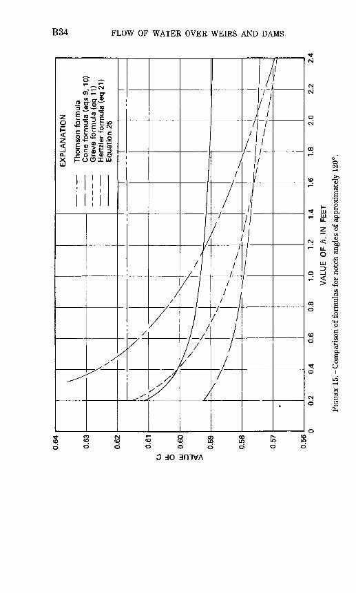
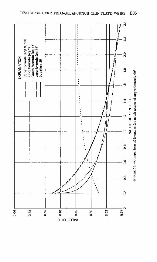
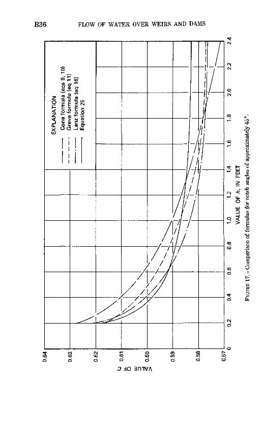
OTHER NOTCH ANGLES
Figures 15 through 19 show comparisons of well-known formulas for weirs with 120°, 60°, 45°, 27°, and 10° notch angles. The solid line in each figure was computed from equation 25, with values of Ce and k^ from figures 12 and 4, respectively. The corresponding comparisons of experimental data are shown in figures 6 and 8 through 11. It is demonstrated again that the solution derived from the effective-head concept is substantiated by the experimental data, whereas the classic formulas show justifiable differences at small values of h.
CONCLUSIONS
The triangular-notch, thin-plate weir is potentially an accurate, con venient means of measuring the flow of liquids. Classic discharge for mulas are inadequate, however, because they fail to recognize the full significance of the pertinent variables. Although the triangular-notch weir is not subject to a completely analytical solution, available ex perimental data are sufficient to substantiate a practical solution which is based on dimensional analysis and experimental coefficients. Limita tions of the data restrict the use of the solution to water.
The equation of discharge proposed in this report is
^5/2 (6) z
in which he, the effective head, is defined by the equation(5)
and values of k^ are shown in figure 4.
DISCHARGE OVER TRIANQULAR-NOTCH THIN-PLATE WEIRS B33
do amvA
0.64
0.63
EX
PL
AN
AT
ION
Th
om
son
fo
rmu
la
Con
e fo
rmu
la (
eqs
9, 1
0)
Gre
ve f
orm
ula
(eq
11)
H
ertz
ler
form
ula
(eq
21)
E
quat
ion
25
0.56
1.0
1.2
1.4
VA
LUE
O
F h
, IN
FE
ET
FIGU
RE 1
5. -C
ompa
riso
n of
form
ulas
for
not
ch a
ngle
s of
app
roxi
mat
ely
120°
.
0.64
0.63
0.62
EX
PL
AN
AT
ION
Con
e fo
rmu
la (
eqs
9, 1
0)
Kin
g fo
rmu
la (
eq 1
9)
Gre
ve f
orm
ula
(eq
11)
Le
nz f
orm
ula
(eq
16)
E
quat
ion
25
0,57
1.6
1.0
1.2
1.4
VA
LUE
OF
h, I
N FE
ET
FIGU
RE 1
6.-C
ompa
riso
n of
form
ulas
for
not
ch a
ngle
s of
app
roxi
mat
ely
60
1.8
2.0
2.2
2.4
CO
Cn
0.64
0.63
EX
PL
AN
AT
ION
Con
e fo
rmu
la (
eqs
9, 1
0) -
G
reve
fo
rmu
la (
eq 1
1)-
Lenz
fo
rmu
la (
eq 1
6)
Equ
atio
n 25
0.57
1.0
1.2
1.4
VA
LUE
O
F h
, IN
FE
ET
FIGU
RE 1
7. -C
ompa
riso
n of
for
mul
as f
or n
otch
ang
les
of a
ppro
xim
atel
y 45
°.
0.65
0.64
EX
PL
AN
AT
ION
Con
e fo
rmu
la (
eqs
9, 1
0) - -
Gre
ve f
orm
ula
(eq
11)
Lenz
fo
rmu
la (
eq 1
6)
Equ
atio
n 25
0.2
0.4
0.6
0.8
1.0
1.2
1.4
1.6
1.8
2.0
2.2
2.4
VA
LUE
O
F h,
IN
FE
ET
0.58
0.57
FIG
URE
18.
-C
ompa
riso
n of
for
mul
as f
or n
otch
ang
les
of a
ppro
xim
atel
y 27
°.
to CO W
co
0.68
0.67
-
Lenz
fo
rmu
la (
eq 1
6)
Equ
atio
n 25
0.61
0.60
0.2
0.4
1.0
1.2
.1.4
VA
LUE
O
F h
, IN
FE
ET
1.6
1.8
2.0
2.2
2.4
FIGU
RE 1
9.-C
ompa
riso
n of
form
ulas
for
not
ch a
ngle
s of
app
roxi
mat
ely
10°.
DISCHARGE OVER TRIANGULAR-NOTCH THIN-PLATE WEIRS B39
In general, the coefficient of discharge, Ce , is an experimentally determined function of the geometric parameters h/P, PIB, and 6. However, within the range of the most common practical limits of h/P and PIB, Ce is a function of 6 alone (fig. 12). In this range, values of Ce computed from the results of experiments by Barr, Cone, Yarnall, Greve, Lenz, and Numachi, Kurokawa, and Hutizawa show remarkable agreement. For 0= 90° the available data are sufficient to define Ce over a wider range of values of hIP and PIB (fig. 13).
REFERENCES
Allerton, R. W., 1932, Flow of water over triangular weirs: Princeton University, Thesis (mech. eng.), 56 p. 29 figs.
Barr, James, 1910, Experiments upon the flow of water over triangular notches: Engi neering (London), v. 89, (April 8 and 15), p. 435 ff.
Burgess, J. S., and White, W. R., 1966, The triangular-profile (Crump) weir-two-dimen sional study of discharge characteristics, Hydraulics Research Station (Wallingford, U.K.), HRS Report INT 52.
Carter, R. W., 1956, A comprehensive discharge equation for rectangular-notch weirs, Master's thesis, Georgia Institute of Technology.
Cone, V. M., 1916, Flow through weir notches with thin edges and full contractions: U.S. Department of Agriculture, Journal of Agricultural Research, v. V, no. 23 (March 6), p. 1051.
Cozzens, H. A., Jr., 1915, Flow over V-notch weirs: Power, v. 42, no. 21 (November 23), p. 714.
Greve, F. W., 1932, Flow of water through circular, parabolic, and triangular vertical- notch weirs: (Purdue Univ., Eng. Bull., v. XVI, no. 2, Research Series No. 40 (March), 84 p., 15 figs.
Hertzler, R. A., 1938, Determination of a formula for the 120° V-notch weir: Civil Eng. (November), p. 756.
Ho, Chitty, and Wu, S. L., 1931, The flow of water over sharp crested weir notches- rectangular, trapezoidal, and triangular: Cornell Univ., Master's thesis, 155 p., 78 figs.
International Standards Organization, 1975, Liquid flow measurement in open channels using thin-plate weirs and venturi flumes (ISO 1438-1975).
Kindsvater, C. E., and Carter, R. W., 1959, Discharge characteristics of rectangular thin-plate weirs: Am. Soc., Civil Engineers Trans., v. 124, p. 772.
Kindsvater, Carl E., 1964, Discharge characteristics of embankment-shaped weirs: U.S. Geol. Survey Water-Supply Paper 1617-A, 114 p., 57 figs.
King, H. W., 1916, Flow of water over right-angled V-notch weir: Univ., Michigan Technic, v. 29, no. 3 (October), p. 189.
1954, Handbook of Hydraulics (Revised by Ernest F. Brater): New York, McGraw-Hill Book Co., 567 p., 165 figs.
Lenz, A. T., 1943, Viscosity and surface tension effects on V-notch weir coefficients: Am. Soc. Civil Engineers Trans., v. 108, p. 759.
Mawson, Humbert, 1927, Applications of the principles of dimensional and dynamical similarity to the flow of liquids through orifices, notches and weirs: Inst. Mech. Engineers, Proc., v. 1, p. 1033.
Numachi, F., Kurokawa, T., and Hutizawa, S., 1940, Uber den Uberfallbeiwert eines rechtwinkelig-dreieckigen Messwehrs: Soc. Mech. Engineeers (Japan) Trans., v. 6, no. 22, (February), p. 110.
B40 FLOW OF WATER OVER WEIRS AND DAMS
1941, Uber den Uberfallbeiwert eines rechtwinkelig-dreieckigen Messwehrs: Tohoku Imperial Univ., (Japan) Tech. reports, v. 13, no. 2, p. 350.
-1943, Uber den Uberfallbeiwert eines rechtwinkelig-dreieckigen Messwehrs, 2.Mitteilung: Tohoku Imperial Univ., (Japan) Tech. reports, v. 13, no. 3, p. 473.
Rehbock, Th., 1929, discussion of paper by Ernest W. Schoder and Kenneth B. Turner, Precise weir measurements: Am. Soc. Civil Engineers Trans., v. 93, p. 1148.
Schlag, Albert, 1962, Note sur la mesure des debits pour deversoir triangulare, La Tri bune de Cebedeau (Liege, Belgium), v. 15, no. 218, p. 22.
1962b, Formule de debit de deversoirs dont le seuil est constitue par une s£rie de dents situees dans un plan horizontal, La Tribune du Cebedeau (Liege, Belgium), v. 15, no. 221, p. 180.
Smith, E. S., Jr., 1934, The V-notch weir for hot water: Am. Soc. Mech. Engineers Trans., v. 56, p. 787.
1935, The V-notch weir for hot water: Am. Soc. Mech. Engineers Trans., v. 57, p. 249.
Strickland, T. P., 1910, Mr. James Barr's experiments upon the flow of water over tri angular notches: Engineering (London), v. 90, (October 28), p. 598.
Switzer, F. G., 1915, Tests of the effect of temperature on weir coefficients: Engineering News, v. 73, no. 13, (April 1), p. 636.
Thomson, James, 1858, On experiments on the measurement of water by triangular notches in weir boards: Brit. Assoc. Adv. Sci., Annual report, p. 181.
1861, On experiments on the measurement of water by triangular notches in weirboards: Brit. Assoc. Adv. Sci., Annual report, p. 151.
Thornton, B. M., 1929, Measurement of fluid flow with triangular notches: PowerEngineer (August), London, v. 24, p. 314.
Tracy, H. J., 1957, Discharge characteristics of broad-crested weirs: U.S. GeologicalSurvey Circ. 397, 15 p., 11 figs.
Yarnall, D. R., 1912, the V-notch weir method of measurement: Am. Soc. Mech.Engineers Trans., v. 34, p. 1055.
1926, Accuracy of the V-notch weir method of measurement: Am. Soc. Mech. Engineers Trans., v. 48, p. 939.
SUPPLEMENTAL INFORMATION
B42 FLOW OF WATER OVER WEIRS AND DAMS
REQUIREMENTS FOR PRECISE MEASUREMENTS
SPECIFICATIONS FOR THE INSTALLATION
Use of the triangular-notch, thin-plate weir for precise measure ments is restricted to steady, free, and fully ventilated flows. The recommended coefficients are applicable for water only, in the approx imate range of temperatures from 40° F to 85° F.
General specifications for a satisfactory weir installation are de scribed on page B2. Additional restrictions related to the actual measurements are discussed below.
RESTRICTIONS ON THE GEOMETRIC PARAMETERS
Values of v less than 20° or greater than 100° are not recommended for precise measurements. Experimental data for weirs outside this range are limited. Furthermore, the data available indicate that weirs with very small and very large notch angles exhibit characteristics of instability which result from the fact that the nappe intermittently clings to the upper surfaces of the crest.
Practical restrictions on hIP and PIE are suggested by the observa tion that head-measurement difficulties and errors result from surges and waves which occur in the approach channel when the velocity of ap proach is large in comparison with the depth of flow. The available data are not adequate to establish the limiting values of hIP and PIB which are associated with this condition. Therefore, the user himself must determine practical limits which are consistent with the required ac curacy for head measurements. These limits are separate from restric tions on the use of figure 12, which is applicable only when the effects of hIP and PIB are negligible.
RESTRICTIONS ON h AND P
Restrictions on the magnitude of h are related to the unpredictable, unsteady clinging phenomena which occur at small heads. To ensure a freely discharging, stable nappe, a minimum value of h=Q.2 foot is recommended.
There is disagreement in the literature regarding an independent correlation between P and the coefficient of discharge. It is tentatively recommended that P be limited to values greater than 0.3 foot.
EFFECT OF NEGLECTING kk
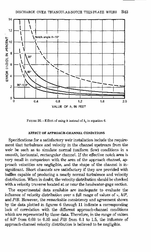
It is apparent from equations 5 and 6 that the relative influence of kh decreases as h increases in magnitude. Consequently, the error which results from using h instead of he in equation 6 is appreciable only for small values of h. The relative error in the discharge is plotted as a function of h in figure 20.
DISCHARGE OVER TRIANGULAR-NOTCH THIN-PLATE WEIRS B43
0.4 0.8 1.2
VALUE OF h, IN FEET
1.6 2.0
FIGURE 20. -Effect of using h instead of he in equation 6.
EFFECT OF APPROACH-CHANNEL CONDITIONS
Specifications for a satisfactory weir installation include the require ment that turbulence and velocity in the channel upstream from the weir be such as to simulate normal (uniform flow) conditions in a smooth, horizontal, rectangular channel. If the effective notch area is very small in comparison with the area of the approach channel, ap proach velocities are negligible, and the shape of the channel is in significant. Short channels are satisfactory if they are provided with baffles capable of producing a nearly normal turbulence and velocity distribution. When in doubt, the velocity distribution should be checked with a velocity traverse located at or near the headwater-gage section.
The experimental data available are inadequate to evaluate the influence of velocity distribution over a full range of values of v, hIP, and PIB. However, the remarkable consistency and agreement shown by the data plotted in figures 6 through 11 indicate a corresponding lack of correlation with the different approach-channel conditions which are represented by those data. Therefore, in the range of values of h/P from 0.03 to 0.35 and PIB from 0.1 to 1.5, the influence of approach-channel velocity distribution is believed to be negligible.
B44 FLOW OF WATER OVER WEIRS AND DAMS
MEASUREMENT OF v
Precise discharge computations require that v be measured accurate ly. One of several satisfactory methods of measuring v is described: (1) two true disks of different, micrometered diameters are placed in the notch with their edges tangent to the sides of the notch; (2) the vertical distance between the centers (or two corresponding edges) of the two disks is measured with a micrometer caliper; (3) the angle v is twice the angle whose sine is equal to the difference between the radii of the disks divided by the distance between the centers of the disks.
Other equally satisfactory methods of measuring v are described in the listed references.
MEASUREMENT OF h
The head is measured with a hook gage, point gage, or precise ma nometer. Hook and point gages preferably are used in a stilling well. However, if approach velocities and surface disturbances in the ap proach channel are negligible, the gages can be mounted over the head water surfaces. Stilling wells and manometers are connected to piezometers located in the floor or walls of the channel. To prevent er rors due to excessive head losses or surface drawdown, the piezometnc section is located upstream from the weir a distance equal to from four to five times the maximum head. Gages are mounted as close to the weir as possible in order to avoid errors in the gage zero due to deflec tion or movement under different water loads.
DETERMINATION OF GAGE ZERO
Accuracy of head measurements is critically dependent upon the determination of the gage zero, which is defined as the gage reading corresponding to the level of the vertex of the notch. Numerous accept able methods of determining the gage zero are in use. One such method is described: (1) still water in the channel upstream from the weir is drawn to a level below the vertex of the notch; (2) a temporary, precise hook gage is mounted over the approach channel, with its point a short distance upstream from the weir plate; (3) a true cylinder of known (micrometered) diameter is placed with its axis horizontal, with one end resting in the notch and the other end balanced on the point of the tem porary hook gage; (4) a machinist's level is placed on the top of the cylinder and the hook gage is adjusted to make the cylinder precisely horizontal; (5) the reading of the temporary gage is recorded; and (6) the temporary hook gage is lowered to the water surface in the ap proach channel and the reading is recorded.
DISCHARGE OVER TRIANGULAR-NOTCH THIN-PLATE WEIRS B45
The permanent headwater gage is adjusted to read the level in the stilling well, and this reading is recorded; (7) the distance from the bot tom of the cylinder to the vertex of the notch is computed with the known values of v and the diameter of the cylinder; (8) the vertical distance from the vertex of the notch to the still surface is computed from the readings in step 5 and 6 and the computation in step 7; (9) finally, the zero reading on the permanent gage is computed as its reading on the still water surface plus the computed distance from the vertex to the still surface. An obvious advantage of this method is that it refers the gage zero to the geometrical vertex which is defined by the sides of the notch.

Studies of Flow of Water Over Weirs and Dams
GEOLOGICAL SURVEY WATER-SUPPLY PAPER 1617
This volume was published as separate chapters A -B
UNITED STATES DEPARTMENT OF THE INTERIOR
JAMES G. WATT, Secretaiy
GEOLOGICAL SURVEY
Doyle G. Frederick, Acting Director
CONTENTS
[Letters designate the chapters]
(A) Studies of Flow of Water Over Weirs and Dams-Discharge Characteristics of Embankment-Shaped Weirs, by Carl E. Kindsvater.
(B) Studies of Flow of Water Over Weirs and Dams-Discharge Characteristics of Triangular-Notch Thin-Plate Weirs, by John Shen.