Embed Size (px)
Citation preview

PDF Cover Page♦ ♦
Engineering and Intuition Serving the Soul of Music❦Perkins Electro-Acoustic Research Lab, Inc.
86008, 2106 33 Ave. SW, Calgary, AB; CAN T2T 1Z6
Ph: +.1.403.244.4434 Fx: +.1.403.245.4456
Web: http: //www.pearl -hifi .com
E-mail: custserv@pearl -hifi .com Inc.
Please note that the links in the PEARL logotype above are “live”and can be used to direct your web browser to our site or to
open an e-mail message window addressed to ourselves.
To view our item listings on eBay, click here.
To see the feedback we have left for our customers, click here.
This document has been prepared as a public service . Any and all trademarks and logotypes used herein are the property of their owners.
It is our intent to provide this document in accordance with the stipulations withrespect to “fair use” as delineated in Copyrights - Chapter 1: Subject Matter and
Scope of Copyright; Sec. 107. Limitations on exclusive rights: Fair Use.
Public access to copy of this document is provided on the website of Cornell Law Schoolat http://www4.law.cornell.edu/uscode/17/107.html and is here reproduced below:
Sec. 107. - Limitations on exclusive rights: Fair Use
Notwithstanding the provisions of sections 106 and 106A, the fair use of a copyrighted work, includ-ing such use by reproduction in copies or phono records or by any other means specified by that section,for purposes such as criticism, comment, news reporting, teaching (including multiple copies for class-room use), scholarship, or research, is not an infringement of copyright. In determining whether the usemade of a work in any particular case is a fair use the factors to be considered shall include:
1 - the purpose and character of the use, including whether such use is of a commercial nature or is for nonprofit educational purposes;
2 - the nature of the copyrighted work;
3 - the amount and substantiality of the portion used in relation to the copy-righted work as a whole; and
4 - the effect of the use upon the potential market for or value of the copy-righted work.
The fact that a work is unpublished shall not itself bar a finding of fair use if such finding is madeupon consideration of all the above factors
AN 7.1 Page 1♦ ♦
THE PEARL ISO-SOCKET IS AVAILABLE in bothchassis-mounting and (printed) circuit board
configurations, either of which can be used in verti-cally- or horizontally-mounted applications. Iso-sock-ets can be used in new construction and retrofit appli-cations where an old socket must first be removed.
This instruction provides installation informa-tion for all configurations as follows:
Sec. 1 - Chassis-mount; vertical installation
Sec. 2 - Chassis-mount; horizontal installation
Sec. 3 - Board-mount,vertical installation; a) new construction
i) printed circuit boardii) point-to-point wired circuit board
b) retrofit to printed circuit board
Sec. 4 - Board-mount,horizontal installation; a) new construction
i) printed circuit boardii) point-to-point wired circuit board
b) retrofit to printed circuit board
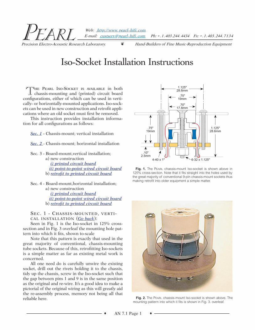
SEC. 1 - CHASSIS-MOUNTED, VERTI-CAL INSTALLATION (Go back):Seen in Fig. 1 is the Iso-socket in 125% cross-
section and in Fig. 3 overleaf the mounting hole pat-tern into which it fits, shown to-scale
Note that this pattern is exactly that used in thegreat majority of conventional, chassis-mountingtube sockets. Because of this, retrofitting Iso-socketsis a simple matter as far as existing metal work isconcerned.
All one need do is carefully unwire the existingsocket, drill out the rivets holding it to the chassis,tidy up the chassis, screw in the Iso-socket such thatthe gap between pins 1 and 9 is in the same positionas the original and re-wire. It’s a good idea to make apictorial of the original wiring as this will greatly aidthe re-assembly process, memory not being all thatreliable here.
Iso-Socket Installation Instructions
Hand-Builders of Fine Music-Reproduction Equipment❦Precision Electro-Acoustic Research Laboratory.
Ph: +.1.403.244.4434 Fx: +.1.403.244.7134
Web: http: //www.pearl -hifi .com
E-mail: custserv@pearl -hifi .com
.75"19mm
.70"17.8mm
.75"19mm
1.125"28.6mm
.10"2.5mm
1.125"28.6mm
4-40 x 1" 6-32 x 1.125"
Fig. 1. The PEARL chassis-mount Iso-socket is shown above in125% cross-section. Note that it fits straight into the holes used bythe great majority of conventional 9-pin chassis-mount sockets thusmaking retrofit into older equipment a simple matter.
Fig. 2. The PEARL chassis-mount Iso-socket is shown above. Themounting pattern into which it fits is shown in Fig. 3. overleaf.
AN 7.1 Page 2♦ ♦
SEC. 2 - CHASSIS-MOUNTED, HORI-ZONTAL INSTALLATION (Go back):Because the vibration isolating/absorbing elas-
tomer used in the Iso-socket is of low and tempera-ture sensitive durometer—durometer being a mea-sure of elastomer softness—unsupported, can-tilevered tubes mounted into horizontally fitted Iso-sockets can droop with both time and temperature.Potential solutions to this problem are two:
1 - the use of a much harder elastomer2 - arrangement of support for the cantilevered
tube.
Because option (1) will essentially ruin the vibra-tion isolation characteristic of the Iso-socket it is notviable.
Option (2) requires the use of either:
a) a temperature resistant, low durometer materialor,
b) fitting and subsequent support of a PEARL tubecooler.
Low durometer, high-temperature resistance, andlong working-life being, at this time, something of amutually exclusive set of elastomer characteristics,option is (a) not viable and we are left to work upanother method of solving the problem.
By fitting and subsequently “softly supporting”a PEARL tube cooler an elastomer used to supportthe tube/cooler will not have to withstand the sortsof temperatures encountered if the elastomer wasplaced in direct contact with the hot envelope of thetube. This is a viable solution and one that we haveimplemented. While we can supply .50” dia. x .25”thick “pads” of elastomer suitable for supporting acooler-fitted tube, arrangements for mounting thepad are very much application-specific and we musttherefore leave the development of such arrange-ments to the installer.
SEC. 3 - BOARD-MOUNTED, VERTICALINSTALLATION (Go back):a) new construction
i) printed circuit boardInstallation of Iso-sockets onto new PCBs is
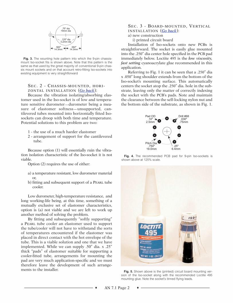
straightforward. The socket is easily glue mountedinto the .250” dia center hole specified in the PCB padimmediately below. Loctite 495 is the low viscosity,fast setting cyanoacrylate glue recommended in thisapplication.
Referring to Fig. 1 it can be seen that a .250” diax .050” long shoulder extends from the bottom of theIso-socket’s mounting surface. This automaticallycenters the socket atop the .250” dia. hole in the sub-strate, leaving only the matter of correctly indexingthe socket with the PCB’s pads. Note and maintainthe clearance between the self-locking nylon nut andthe bottom side of the substrate, as shown in Fig. 1.
.75" dia19mm dia
.562" 14.3mm
.562" 14.3mm
.125" dia3.2mm dia
Fig. 3. The Mounting hole pattern into which the 9-pin chassis-mount Iso-socket fits is shown above. Note that this pattern is thesame as that used by the great majority of conventional 9-pin chas-sis mount sockets and on that account retro-fitting Iso-sockets intoexisting equipment is very straightforward
Fig. 5. Shown above is the (printed) circuit board mounting ver-sion of the Iso-socket along with the recommended Loctite 495mounting glue. Note the socket’s tinned flying leads.
.25" 6.4mm
Drill #68 .030"
.75mm
Pad OD.10"
2.5mm
Pitch Dia..750"
19.0mm
Fig. 4. The recommended PCB pad for 9-pin Iso-sockets isshown above at 125% scale.
AN 7.1 Page 3♦ ♦
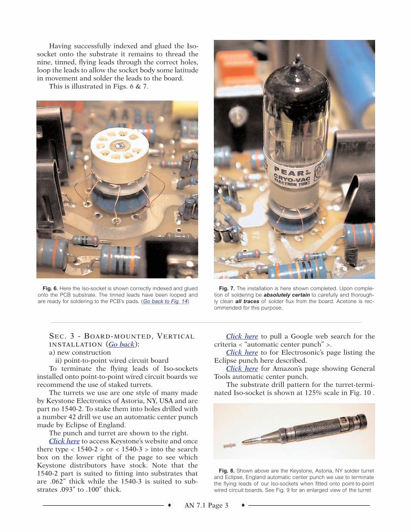
Having successfully indexed and glued the Iso-socket onto the substrate it remains to thread thenine, tinned, flying leads through the correct holes,loop the leads to allow the socket body some latitudein movement and solder the leads to the board.
This is illustrated in Figs. 6 & 7.
Fig. 6. Here the Iso-socket is shown correctly indexed and gluedonto the PCB substrate. The tinned leads have been looped andare ready for soldering to the PCB’s pads. (Go back to Fig. 14)
Fig. 7. The installation is here shown completed. Upon comple-tion of soldering be absolutely certain to carefully and thorough-ly clean all traces of solder flux from the board. Acetone is rec-ommended for this purpose.
SEC. 3 - BOARD-MOUNTED, VERTICALINSTALLATION (Go back):a) new construction
ii) point-to-point wired circuit boardTo terminate the flying leads of Iso-sockets
installed onto point-to-point wired circuit boards werecommend the use of staked turrets.
The turrets we use are one style of many madeby Keystone Electronics of Astoria, NY, USA and arepart no 1540-2. To stake them into holes drilled witha number 42 drill we use an automatic center punchmade by Eclipse of England.
The punch and turret are shown to the right.Click here to access Keystone’s website and once
there type < 1540-2 > or < 1540-3 > into the searchbox on the lower right of the page to see whichKeystone distributors have stock. Note that the1540-2 part is suited to fitting into substrates thatare .062” thick while the 1540-3 is suited to sub-strates .093” to .100” thick.
Click here to pull a Google web search for thecriteria < “automatic center punch” >.
Click here to for Electrosonic’s page listing theEclipse punch here described.
Click here for Amazon’s page showing GeneralTools automatic center punch.
The substrate drill pattern for the turret-termi-nated Iso-socket is shown at 125% scale in Fig. 10 .
Fig. 8. Shown above are the Keystone, Astoria, NY solder turretand Eclipse, England automatic center punch we use to terminatethe flying leads of our Iso-sockets when fitted onto point-to-pointwired circuit boards. See Fig. 9 for an enlarged view of the turret
AN 7.1 Page 4♦ ♦
SEC. 3 - BOARD-MOUNTED, VERTICALINSTALLATION (Go back):b) retrofit to printed circuit boardIn this section it is assumed that an existing socket
must be removed from a printed circuit board beforethe Iso-socket can be installed.
While there are various methods to remove theexisting socket, you need to know that there are sev-eral ways that you can cause both physical and elec-trical damage if great care is not exercised.
Many designs of the last few years have beenhybrids, using both tubes and solid-state devices—bipolar, FET, and MOSFET. While bipolar devicesare slightly more tolerant of static discharge than(MOS)FETs, it’s good practice to treat all deviceswith the same care.
Quite often the base or gate of a device will beconnected directly to one of the tube elements, andbeing so wired is subject to static assault from anyprocedures used to replace the socket. Therefore,get the schematic of the piece of gear you are plan-ning to modify and see if the possibility of damageto solid-state devices exists. If it does, simply usestandard, static precautions and, additionally, wirea temporary jumper from gate to source or frombase to emitter of any devices connecting directly tothe tube. Remember to remove the jumpers whenyou are finished…
For those unfamiliar with the desoldering ofmulti-legged devices, the simplest and safestapproach is to find a reputable company in yourarea doing board-level computer repairs. They willbe replacing multi-pin, static-sensitive devices everyday and can easily wire in the temporary anti-staticsafety jumpers, remove your old sockets, re-routeany PC traces that run directly under the originalsocket, and fit the Iso-Sockets.
If you want to do the job yourself, the easiestway is to snip the leads off the socket from the com-ponent side of the PC board, thereby freeing theplastic body of the socket. From there it’s a simplematter to individually unsolder the remaining stubsof socket lead. Use solder wick or a solder-suckertool to prevent damage to the PC board by the inad-vertent application of too much heat. If the equip-ment is laid out so that you can’t get at the socketleads from the top, you’ll have to do the job the old-fashioned way. You’ll need at minimum some solderwick and a manual desoldering pump is a great help.
Remove as much of the joint as possible using thepump and use the wick to pull out the rest. When youhave cleaned out as much solder as you can, use apair of needle-nosed pliers to grasp the socket pin inquestion and re-heat the joint. When the remainingsolder melts move the pin away from the side walls tothe center of the hole. Either hold it there until the PCpad cools off, or wiggle it slightly so that any jointthat’s made by the remaining solder is a cold one andtherefore mechanically weak. Repeat this procedurefor all of the pins. Having done so, just a little luckwill result in the socket pulling free with only a gen-tle, wiggling tug. If not, find out which pins are stillstuck, and repeat the “cold joint, wiggling procedure”until the socket can finally be pulled free of the PCboard. Do not use excessive force, as this can result inthe removal of the through-plating, the via,betweenthe top- and bottom-side traces on a double-sided PCboard. Sometimes this will happen regardless, soalways solder the flying leads from the new Iso-sock-et onto the PC pads on both sides of the board.
Clean the board thoroughly with a solvent suchas acetone prior to fitting the new sockets. Afterinstalling the Iso-sockets remember to remove theanti-static, safety jumpers.
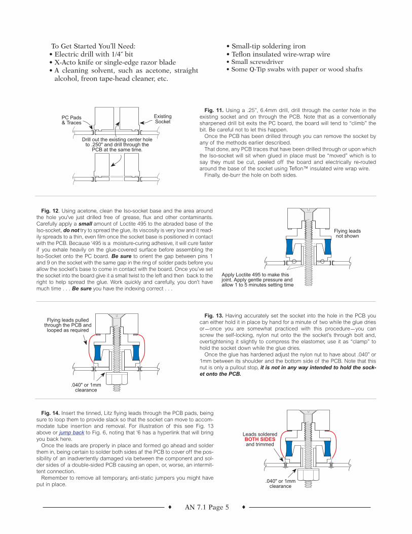
.25" 6.4mm
Drill #42 .094"
2.4mm
Pitch Dia..750"
19.0mm
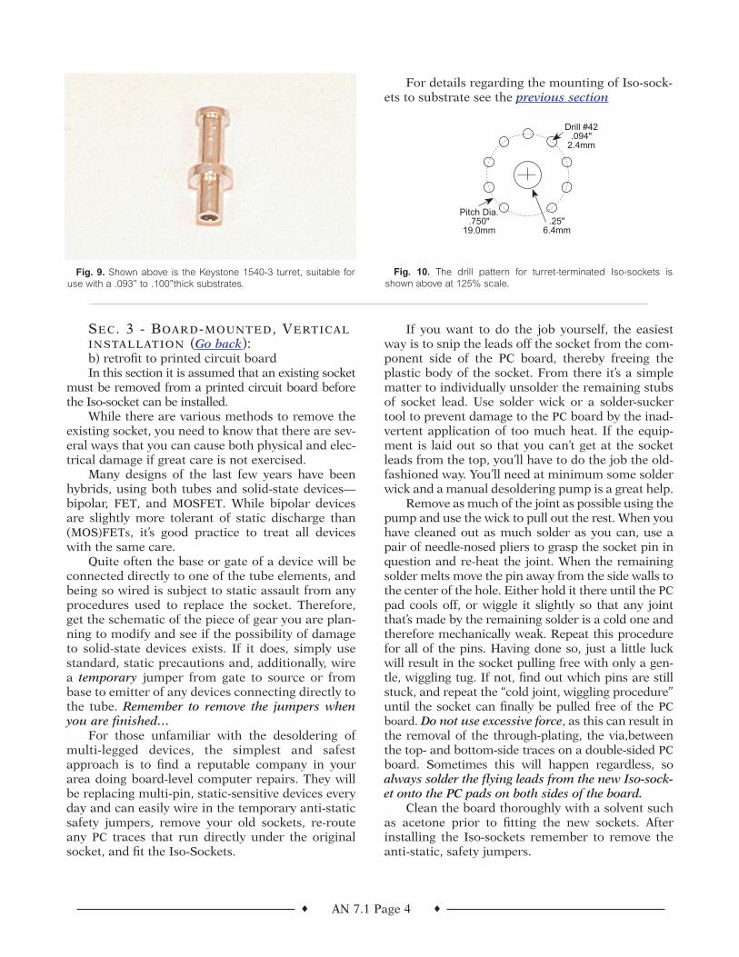
Fig. 9. Shown above is the Keystone 1540-3 turret, suitable foruse with a .093” to .100”thick substrates.
Fig. 10. The drill pattern for turret-terminated Iso-sockets isshown above at 125% scale.
For details regarding the mounting of Iso-sock-ets to substrate see the previous section
AN 7.1 Page 5♦ ♦
Fig. 11. Using a .25”, 6.4mm drill, drill through the center hole in theexisting socket and on through the PCB. Note that as a conventionallysharpened drill bit exits the PC board, the board will tend to “climb” thebit. Be careful not to let this happen.
Once the PCB has been drilled through you can remove the socket byany of the methods earlier described.
That done, any PCB traces that have been drilled through or upon whichthe Iso-socket will sit when glued in place must be “moved” which is tosay they must be cut, peeled off the board and electrically re-routedaround the base of the socket using Teflon™ insulated wire wrap wire.
Finally, de-burr the hole on both sides.
Fig. 12. Using acetone, clean the Iso-socket base and the area aroundthe hole you've just drilled free of grease, flux and other contaminants.Carefully apply a small amount of Loctite 495 to the abraded base of theIso-socket, do not try to spread the glue, its viscosity is very low and it read-ily spreads to a thin, even film once the socket base is positioned in contactwith the PCB. Because ‘495 is a moisture-curing adhesive, it will cure fasterif you exhale heavily on the glue-covered surface before assembling theIso-Socket onto the PC board. Be sure to orient the gap between pins 1and 9 on the socket with the same gap in the ring of solder pads before youallow the socket’s base to come in contact with the board. Once you’ve setthe socket into the board give it a small twist to the left and then back to theright to help spread the glue. Work quickly and carefully, you don’t havemuch time . . . Be sure you have the indexing correct . . .
Fig. 13. Having accurately set the socket into the hole in the PCB youcan either hold it in place by hand for a minute of two while the glue driesor—once you are somewhat practiced with this procedure—you canscrew the self-locking, nylon nut onto the the socket’s through bolt and,overtightening it slightly to compress the elastomer, use it as “clamp” tohold the socket down while the glue dries.
Once the glue has hardened adjust the nylon nut to have about .040” or1mm between its shoulder and the bottom side of the PCB. Note that thisnut is only a pullout stop, it is not in any way intended to hold the sock-et onto the PCB.
.040" or 1mmclearance
Leads solderedBOTH SIDESand trimmed
Fig. 14. Insert the tinned, Litz flying leads through the PCB pads, beingsure to loop them to provide slack so that the socket can move to accom-modate tube insertion and removal. For illustration of this see Fig. 13above or jump back to Fig. 6, noting that ‘6 has a hyperlink that will bringyou back here.
Once the leads are properly in place and formed go ahead and solderthem in, being certain to solder both sides af the PCB to cover off the pos-sibility of an inadvertently damaged via between the component and sol-der sides of a double-sided PCB causing an open, or, worse, an intermit-tent connection.
Remember to remove all temporary, anti-static jumpers you might haveput in place.
Drill out the existing center holeto .250" and drill through the
PCB at the same time.
ExistingSocket
PC Pads & Traces
Flying leads not shown
Apply Loctite 495 to make this joint. Apply gentle pressure and allow 1 to 5 minutes setting time
.040" or 1mmclearance
Flying leads pulled through the PCB and looped as required
To Get Started You’ll Need:• Electric drill with 1/4˝ bit• X-Acto knife or single-edge razor blade• A cleaning solvent, such as acetone, straight
alcohol, freon tape-head cleaner, etc.
• Small-tip soldering iron • Teflon insulated wire-wrap wire • Small screwdriver • Some Q-Tip swabs with paper or wood shafts
Science and Invention for September, 1926
NOTEAll Van Horne Tubes
are UnconditionallyGuaranteed
3 VBX Dry CellDetector Amplifier
An unusually high readingdry cell tube due to the useof patented, thoriated tung-sten filament. Exceptionallysatisfactory where volumewith clearness and signalcarrying capacity is desired.
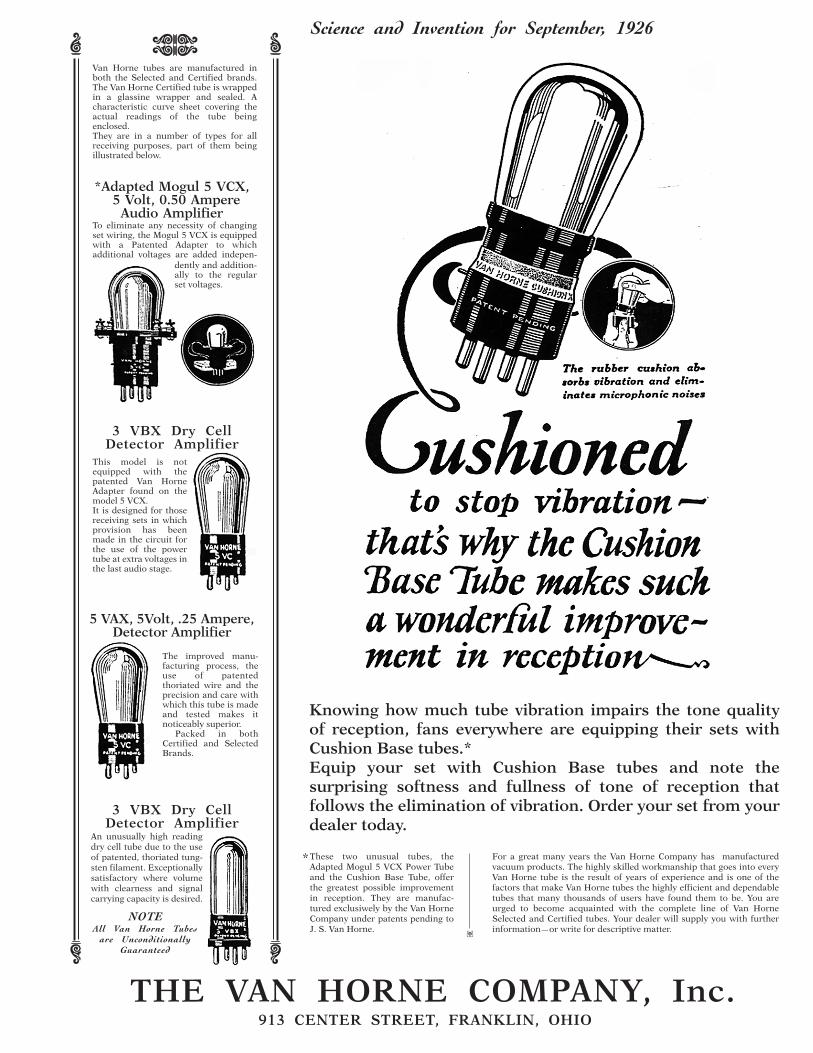
Van Horne tubes are manufactured in both the Selected and Certified brands.The Van Horne Certified tube is wrapped in a glassine wrapper and sealed. A characteristic curve sheet covering the actual readings of the tube being enclosed.They are in a number of types for all receiving purposes, part of them being illustrated below.
5 VAX, 5Volt, .25 Ampere, Detector Amplifier
3 VBX Dry CellDetector Amplifier
*Adapted Mogul 5 VCX, 5 Volt, 0.50 Ampere
Audio AmplifierTo eliminate any necessity of changing set wiring, the Mogul 5 VCX is equipped with a Patented Adapter to which additional voltages are added indepen-
dently and addition-ally to the regular set voltages.
This model is not equipped with the patented Van Horne Adapter found on the model 5 VCX.It is designed for those receiving sets in which provision has been made in the circuit for the use of the power tube at extra voltages in the last audio stage.
The improved manu-facturing process, the use of patented thoriated wire and the precision and care with which this tube is made and tested makes it noticeably superior. Packed in both Certified and Selected Brands.
THE VAN HORNE COMPANY, Inc.913 CENTER STREET, FRANKLIN, OHIO
Knowing how much tube vibration impairs the tone quality of reception, fans everywhere are equipping their sets with Cushion Base tubes.*Equip your set with Cushion Base tubes and note the surprising softness and fullness of tone of reception that follows the elimination of vibration. Order your set from your dealer today.
These two unusual tubes, the Adapted Mogul 5 VCX Power Tube and the Cushion Base Tube, offer the greatest possible improvement in reception. They are manufac-tured exclusiwely by the Van Horne Company under patents pending to J. S. Van Horne.
* For a great many years the Van Horne Company has manufactured vacuum products. The highly skilled workmanship that goes into every Van Horne tube is the result of years of experience and is one of the factors that make Van Horne tubes the highly efficient and dependable tubes that many thousands of users have found them to be. You are urged to become acquainted with the complete line of Van Horne Selected and Certified tubes. Your dealer will supply you with further information—or write for descriptive matter.�