Embed Size (px)
Citation preview

ASIPP
Plasma Facing Components (PFCs) for Magnetic Confined Fusion Devices
G. -N. Luo
Division of Fusion Reactor Materials Science & Technology
Institute of Plasma Physics, CAS, Hefei, Anhui, 230031 China
Joint ICTP/CAS/IAEA School & Workshop on PMI
in Fusion Devices, July 18-22, 2016, Hefei, China

ASIPP
Outline
Fusion reactor
What are PFCs
PFCs for EAST
PFCs for ITER
PFCs for DEMO
2016/7/18 Plasma Facing Components 2

ASIPP
Outline
Fusion reactor
2016/7/18 Plasma Facing Components 3
ASIPP
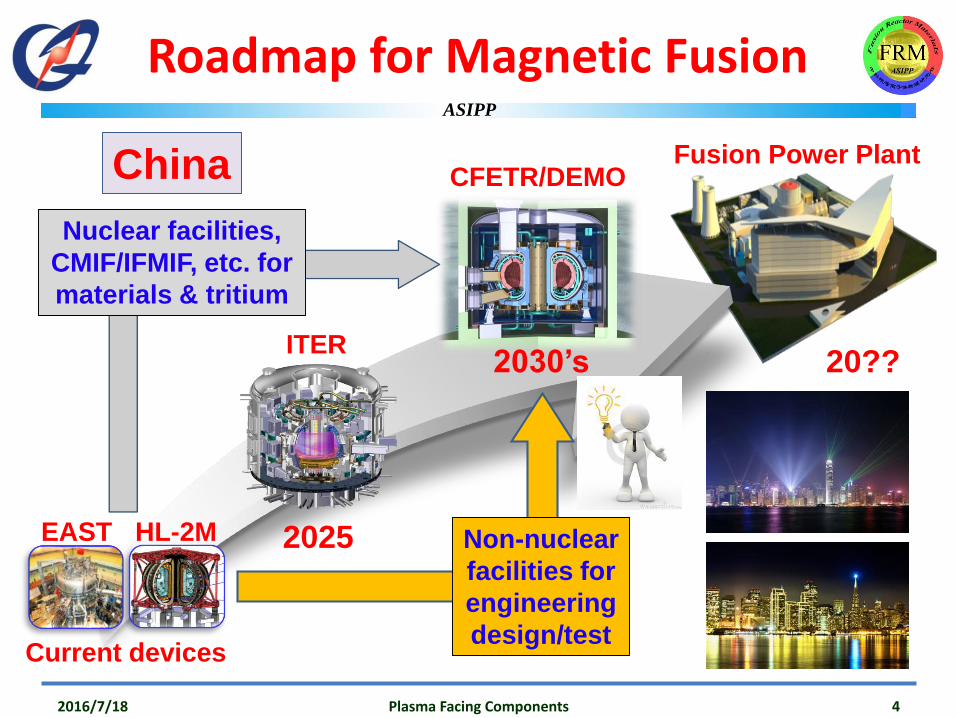
Roadmap for Magnetic Fusion
Non-nuclear
facilities for
engineering
design/test
20??
CFETR/DEMO
Current devices
Fusion Power Plant
EAST HL-2M 2025
2030’sITER
Nuclear facilities,
CMIF/IFMIF, etc. for
materials & tritium
China
2016/7/18 Plasma Facing Components 4

ASIPP
China Fusion Engineering Testing Reactor (CFETR)
2016/7/18 Plasma Facing Components 5
Blanket
Divertor
Cryostat
Port plug
CD & H
SC Magnets
CASKVacuum vessel
Diagnostics
And tritium plant, power supplies, vacuum, cooling, cryogenics,
remote handling, hot lab for maintenance, etc., subsystems!
ASIPP
Outline
What are PFCs?
2016/7/18 Plasma Facing Components 6
ASIPP
What are PFCs?
2016/7/18 Plasma Facing Components 7
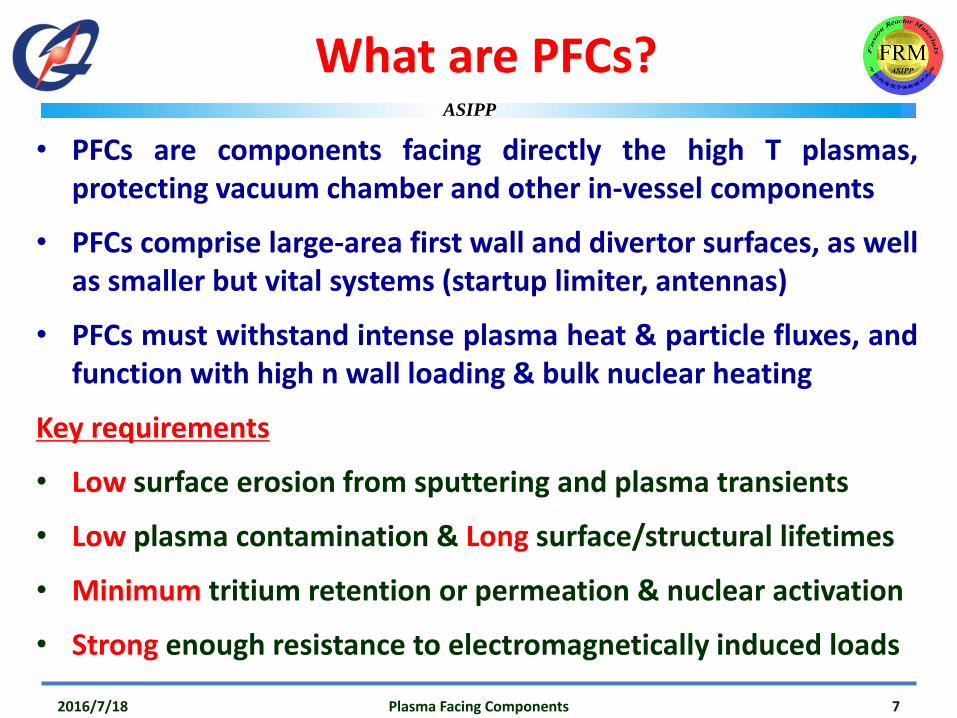
• PFCs are components facing directly the high T plasmas,protecting vacuum chamber and other in-vessel components
• PFCs comprise large-area first wall and divertor surfaces, as wellas smaller but vital systems (startup limiter, antennas)
• PFCs must withstand intense plasma heat & particle fluxes, andfunction with high n wall loading & bulk nuclear heating
Key requirements
• Low surface erosion from sputtering and plasma transients
• Low plasma contamination & Long surface/structural lifetimes
• Minimum tritium retention or permeation & nuclear activation
• Strong enough resistance to electromagnetically induced loads
ASIPP
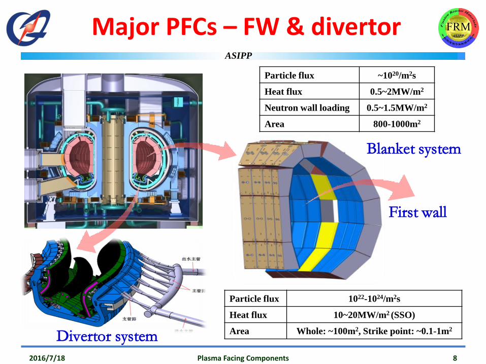
Major PFCs – FW & divertor
Blanket system
Particle flux ~1020/m2s
Heat flux 0.5~2MW/m2
Neutron wall loading 0.5~1.5MW/m2
Area 800-1000m2
Particle flux 1022-1024/m2s
Heat flux 10~20MW/m2 (SSO)
Area Whole: ~100m2, Strike point: ~0.1-1m2
2016/7/18 Plasma Facing Components 8
First wall
Divertor system

ASIPP
Harsh environments
Extreme T
& gradientsSC CoilsFW/DivEdge PlasmaCore Plasma
~108 K ~105 K ~103 K ~3 K
5.7m
2016/7/18 Plasma Facing Components 9

ASIPP
Harsh environments
Magnetic field
High field side : 10-18T
Core space: 6-10T
Low field side : 4-6T
Variation with space : several T/m
Variation with time : several T/s +
2016/7/18 Plasma Facing Components 10

ASIPP
Key issues of PFCs
• Choice of materials and coolants
• Joining of PFM and heat sink material
• Capability of power handling (HHF testing)
• Reliability and integrity of PFCs in operation
• Effect of neutron irradiation on the joints
• Quality control of mass production
• …………
2016/7/18 Plasma Facing Components 11
The PFCs will be crucial both for achievable plasma performance & machine availability!

ASIPP
Materials for PFCs
PFM – carbon based (C & CFC), beryllium, refractory (W & Mo)
2016/7/18 Plasma Facing Components 12
C/CFC Be W (Mo)
Advantage
1. Low Z material2. Compatible with
plasma3. No melting
1. Low Z material2. Medium retention3. Oxygen uptaker
1. Lowest sputtering2. Highest melting point3. High thermal conductivity4. Low retention
Disadvantage
1. High sputtering 2. Chemical erosion3. High codeposition4. High retention
1. Low melting point2. High sputtering3. Toxicity
1. High Z material2. Brittle material3. H/He effects
Heat sink – CuCrZr alloy and RAFM steels (possible ODS-strengthened)
CuCrZr RAFM
Advantage1. High thermal conductivity2. Good mechanical properties
1. Low neutron activation2. Good mechanical properties
Disadvantage
1. Degradation of mechanical properties after annealing
2. Radiation hardening3. Neutron activation
1. Low thermal conductivity2. Difficult in joining (especially for
the ODS ones)

ASIPP
Cooling for PFCs
2016/7/18 Plasma Facing Components 13
Coolant Inertial Water Helium
Advantage
1. Easy to
manufacture,
inspect and
install
2. No leakage risk
1. High capability of
power handing
(20MW/m2)
2. Good performance
of steady state
heat flux
1. Medium capability
of power handing
(10MW/m2)
2. Feasibility of high
temperature wall
operation
Disadvantage
1. Low capability
of power
handling
1. Difficult to join
PFM and heat sink
2. High temperature
gradient of PFCs
1. Very difficult to
manufacture and
inspect
2. Low reliability
• Inertial cooling – power removal via heat capacity & radiation• Active cooling – heat removal by pressurized water or helium

ASIPP
Water cooled PFCs – flat plate
• Advantage:
– High heat transfer capability
– Easy to manufacture and inspect
– Withstand heat loads of ~5MW/m2
• Disadvantage:
– Singularity of thermal stress
– Peeling-off in case of interface failure
2016/7/18 Plasma Facing Components 14
Flat plate PFC w/ hypervapotroncooling structure
Flat plate PFC w/ round cooling tube
HIP / VHPVPS/CVD/PVD
VHP/
Brazing
or pure Ti or filler interlayer
or Be or C

ASIPP
Water cooled PFCs – monoblock
2016/7/18 Plasma Facing Components 15
• Advantage:– Lower thermal stress than flat plate
– Intrinsic safety in case of failure (no peeling)
– Withstand heat loads of 10-20MW/m2
• Disadvantage:– Difficult to manufacture and inspect
– Very expensive
BrazingHIP & HRP (diffusion bonding)
AMC (CFC)Brazing (CFC)Direct Cu casting
CFC or W
CuCrZr tube
Cu interlayer

ASIPP
Helium cooled PFCs – design
• High wall temperature to reduce hydrogen retention and recycling
• Pressurized helium jetting flow to reinforce heat transfer capability
• Difficult to manufacture and inspect
2016/7/18 Plasma Facing Components 16
M.S. Tillack, et al, FED 86 (2011) 71-98
P. Norajitra, et al, JNM 386-388(2009)813-816

ASIPP
Thermal stress – analyses
• Large difference of thermal expansion btw PFM and heat sink (HS)
• Debonding of PFM/HS joints• Leaking of HS and other joints
2016/7/18 Plasma Facing Components 17
0
2
4
6
8
10
12
14
16
18
Be CFC W
1E
-6 m
/m
Cu alloy
Thermal expansion coeff. at 3000C Thermal stress distri. at 20MW/m2
F. Crescenzi, et al, FED 89 (2014) 985-990

ASIPP
Electromagnetic (EM) loads
• Plasma instabilities such as disruptions and vertical displacement events (VDEs), give rise to severe EM transients, and thus strong forces on PFCs and other in-vessel components.
2016/7/18 Plasma Facing Components 18
• These can be calculated via combining the plasma simulation code like DINA for time variation of plasma and halo currents, with the finite element code like ANSYS-EM. Sunil Pak, et al, FED 88 (2013) 3224-3237

ASIPP
PFCs for EAST
2016/7/18 Plasma Facing Components 19

ASIPP
PFMC evolution in EAST
2016/7/18 Plasma Facing Components 20
W
Mo
C
Mo
Mo
Full C PFC Mo-FW + C-Div
2008 2012
1st plasma
2014
W&C-Div+Mo-FWFull SS PFC
2006
C
2018~2019 / Full W PFC
WW
C C

ASIPP
Design of W/Cu divertor
2016/7/18 Plasma Facing Components 21
EAST goal: long-pulse high performance plasma operation
Conceptual design Engineering design

ASIPP
Design of W/Cu PFCs
• 15000 Monoblocks
• 720 Monoblock PFUs
• 240 Flat type PFUs
2016/7/18 Plasma Facing Components 22
Dual chamfering for EAST
80 Cassette Bodies

ASIPP
Flowchart of manufacturing
2016/7/18 Plasma Facing Components 23
W powder
W compact
sintering
rolling
W plate
Cu,Cr&Zr
Ingot
melting
CuCrZr platerolling
Cu,Cr&Zr
Ingot
melting
CuCrZr tubesdrawing
W block W bar
Pure CuHIP HIP
W/Cu monoblock
NDT NDT
NDT
W/Cu slice
HIP Machining
W/Cu mono-block PFUs Baffle Dome upper Dome lowerpanel
EBW of two halves+legs+in/outlets
DOME
EBW of endcup+PFUs+trans-plate+baffle+legs+in/outlets
Target
Assembly to CB and in-vessel installation
He leak check at 1.5MPa/180℃
HIP
NDT+leak check
NDTNDT
NDT
Raw mater.
PFU manuf.
Assembly

ASIPP
ITER-like monoblock W/Cu PFC
2016/7/18 Plasma Facing Components 24
• W/Cu monoblocks prepared employing Hot Isostatic Pressing (HIP) technology (9000C, 100MPa)
• W/Cu PFUs manufactured successfully by HIP technology (6000C, 100MPa), properties of CuCrZr after HIP satisfy the requirement
• US-NDT results: Bondings between monoblocks/OFC/CuCrZr excellent
Annealing behavior of CuCrZr tube

ASIPP
Flat-plate W/Cu PFCs
• Casting + HIP: The interface of W/Cu were joined by casting (1200⁰C), and then the interface of Cu/CuCrZr was bonded by HIP at lower temperature of 500~600⁰C.
• NDT results: bondings between W tiles/OFC/CuCrZr plate excellent
252016/7/18 Plasma Facing Components
BAFFLE
Plate

ASIPP
Parts joining: E-beam welding
2016/7/18 26
• Joining between monoblockunits with endbox/manifold and flat baffle
• Joining of two-half parts for dome structural design
• Supporting legs and inlet/outlet cooling tubes joined to CuCrZrheat sink
• EB: 60kV, max 100mA; Seam: > 3mm deep, ~1mm wide at surface
1.2 mm
3.1 mm
CuCrZr
Plasma Facing Components

ASIPP
E-beam HHF testing
W/Cu monoblock PFU: survived 1000 cycles of heat load of 10MW/m2, cooling water of 4m/s, 20⁰C, 15s/15s on/off cycles
W/Cu flat type mock-up: 1000 cycles, 5MW/m2, 4m/s, 20⁰C
2016/7/18 Plasma Facing Components 27

ASIPP
2016/7/18 Plasma Facing Components 28
US-NDT for W/Cu PFCs
US-NDT for
monoblock PFU
NDT for flat
type PFU
• Single probe: scanning the inner surface
• The defects of Φ1mm in the interface of W/Cu and Cu/CuCuZr was detected clearly using this set-up
• 15000 W/Cu mono-blocks and 720 PFUs tested
• More than 30000 W/Cu slices and 240 flat PFUs have been tested by this set-up with detection limit of Φ1mm

ASIPP
Helium leak detection for PFCs
2016/7/18 Plasma Facing Components 29
• Evaluation of welding quality and reliability for EAST OVT, IVT and DOMEcomponents
• During baking: @ 180⁰C for 20 min under 1.5 MPa (He inside)
• Background vacuum: < 5.4x10⁻³Pa; leak level: 2x10-11 Pa.m3.s-1
• Acceptance criteria: 1x10⁻¹⁰ Pa.m3.s-1
• 240 components (80 OVT, 80 IVT, 80 DOME) were tested

ASIPP
W(upper) + C (lower) divertors + Mo-FW
2016/7/18 Plasma Facing Components 30
W
C
Mo

ASIPP
H port dedicated to PWI research on EAST
- Maximum sample weight: 25kg
- Sample holder moving velocity:
1- 15mm/s
- Maximum sample diam.: 500mm
- Can insert into LCFS
- Sample water-cooling & heating
- Gas puffing system
- Diagnostics: Langmuir probes,
thermocouples, spectroscopy, …
Material and Plasma Evaluation System
(MAPES)
2016/7/18 Plasma Facing Components 311

ASIPP
Multiple diagnostics for PWI research on EAST
attached detached
Divertor detachment
Multichannel optical system
Divertor gas
puff system
Edge Langmuir probes
Laser Induced
Breakdown
/Ablation
Spectroscopy
(LIBS/LIAS)International collaboration
High resolution
spectrometer
Post-
mortem
analysis
2016/7/18 Plasma Facing Components 322

ASIPP
W monoblock shaping
2016/7/18 Plasma Facing Components 33
# 52102
Outer divertor
Tolerance of W PFC surface- Toroidal: 2 mm- Neighbor: 0.5 mm Monoblock shaping
- dual 1mm×1mm chamfering
W monoblockgeometry optimization for steady condition
X.H. Chen et al, FED 2016
Bt

ASIPP
Effective W Sputtering Yields in EAST
2016/7/18 Plasma Facing Components 34
W erosion yield governed by C ion bombardment
Better W erosion yield suppression by Li coating
compared to Si one, lower than those in ASDEX
Upgrade, but still higher than that in JET

ASIPP
ELM Dominated W Erosion in H Mode Discharge
2016/7/18 Plasma Facing Components 35
-10 -5 0 5 10 15
0
2
4
6
0
2
4
6
8
10
12
14
R-Rosp
(cm)
W atom (intra-ELM)
W atom (inter-ELM)
Js (intra-ELM)
Js (inter-ELM)
EAST #: 59950 DN / 2.3T
W a
tom
flu
x 1
01
9 /
(m
2 s
)
Js (
A /
cm
2)
W erosion during ELM accounts for about 70%
of total W erosion amounts in an ELM cycle on
average.
Intra-ELM W influx arises from proximity of
outer strike point and Inter-ELM W flux peaks
slightly away from outer strike point.
0
0.5
WI 400.9nm
2016 EAST Shot: 59950
0
2
CII 426.7nm
10
13 p
ho
to
ns
/(s
cm
2 s
r)
0
1
2Si II 413.1nm
0
10Js
A c
m-2
4.4 4.45 4.5 4.55 4.6 4.65 4.7 4.75 4.8 4.85 4.90
0.5
1
Time ( s )
MW
m-2
Peak q

ASIPP
2016/7/18 Plasma Facing Components 36
PFCs for ITER

ASIPP
ITER PFCs
• PFCs in ITER are mainly divided into two regions based on their different functions:
– Shielding Blanket (First Wall)
– Divertor
• All of PFCs are designed as multi-modules, which can be installed and uninstalled by remote handing, considering future radioactive case.
• ITER is a Nuclear Facility INB-174 (in France).
(First Wall)
2016/7/18 37Plasma Facing Components

ASIPP
FW(Blanket)
• Major functions:– Absorbing radiation and particle heat
fluxes from the plasma– Contribute to shielding to reduce heat and
neutron loads in the vacuum vessel and ex-vessel components
– Provide limiting surfaces that define the plasma boundary during start-up and shutdown
– Provide passage for the plasma diagnostics• Procurement:
– First wall (NHF) – EUDA ~50%– First wall (EHF) – RFDA ~40%, CNDA ~10%– Shield block – CNDA ~50%, KODA ~50%– Blanket modules – RFDA ~40%
• Materials – FW: flat Be/Cu/SS; Shield block: SS
2016/7/18 38Plasma Facing Components
FW
Block
Block
FW

ASIPP
FW/Blanket
2016/7/18 39Plasma Facing Components
B. Bigot, Progress towards fusion at ITER, ICFRM-17, Aachen, Germany, 11-16 Oct. 2015

ASIPP
Divertor
• Major functions:
– To minimize the impurity content of the plasma
– To absorb radiation and particle heat fluxes from the plasma while allowing neutral particles to be exhausted to the vacuum system
– Provide passage for the plasma diagnostics
– Provide shielding to VV and external components
• Procurement:
– Outer Vertical Target – JADA
– Inner Vertical Target – EUDA
– Dome –RFDA
– Cassette and Integration – EUDA
2016/7/18 40Plasma Facing Components
B. Bigot, Progress towards fusion at ITER, ICFRM-17, Aachen, Germany, 11-16 Oct. 2015

ASIPP
Divertor
• Vertical Target Plasma-Facing Unit
– Monoblock with swirl tape at high heat flux handing area
– W armour/OFCu/CuCrZr-IG
– Tube to tube joint CuCrZr-IG/ Alloy625/ 316L pipe
• Dome Plasma-Facing Unit
– W/Cu flat tile with CuCrZr/316L(N)-IG hypervapotron coolant channel
2016/7/18 41Plasma Facing Components

ASIPP
Divertor
2016/7/18 42Plasma Facing Components

ASIPP
Divertor
2016/7/18 43Plasma Facing Components

ASIPP
Divertor
2016/7/18 44Plasma Facing Components

ASIPP
High Heat Flux Testing
Location: Efremov Institute, St-
Petersburg, Russia
Purpose: Performance and series tests
of Divertor PFCs
Operating principle: HHFT of
component’s surface by e-beam
Maximum beam power: 800 kW
Maximum accelerating voltage: 60kV
Vacuum level: 10-5 mbar
Advanced system of diagnostics
2016/7/18 Plasma Facing Components 45
ITER Divertor Test Facility (IDTF)
R.A. Pitts, et al., 18th ITPA DivSOL Topical Meeting, Hefei, China, 19-22 March 2013

ASIPP
HHFT on OVT PFUs
• Heat loads: 10s on and 10s off
• Target of Thermal hydraulic parameters:
Inlet: 3.9 MPa; 11 m/s; 70 ⁰C to be used in ITER
2016/7/18 Plasma Facing Components 46
5 x 4 monoblocks
Window type mask
• Straight W part of PFUs subjected to the tests:
20 monoblocks of 12mm (axial) x 28mm(poloidal) x 8 mm (thickness at the top of the tube)

ASIPP
HHF test results
• No significant increase of Tsurf
observed for 5000 cycles testing at 10MW/m2
• No sudden crack openings at the W/OFC-OFC/Cu joints during whole testing
2016/7/18 Plasma Facing Components 47
300 400 500 600 700 800 900 1000
1900
1950
2000
2050
2100
2150
Te
mp
era
ture
, [0
C]
Number of cycle
Normal (IR) (13 tile) Hottest (IR) (15 tile) Pyrometer (13 tile)
Average surface temperature
Successfully withstand 5000 cycles at10MW/m2 + 1000 cycles at 20MW/m2
20MW/m2

ASIPP
2016/7/18 Plasma Facing Components 48
PFCs for DEMO

ASIPP
DEMO PFCs
• Higher heat flux, longer pulses, higher duty factor
‒ 4x ITER’s heat flux
‒ 5000x longer pulses
‒ 5x higher even short-term average duty factor
• Erosion, dust production, tritium retention and component lifetime issues are
much more challenging due to DEMO’s mission
‒ DEMO must show practical solutions that allow for continuous operation for
at least 2 full-power years between PFC change outs
‒ ITER plans to change out divertors after ~ 0.08 full-power years – at much
lower power
• Many solutions used on ITER are not Demo-relevant
‒ Moderate fraction of radiated power
‒ Intermittent dust collection and tritium clean-up
2016/7/18 Plasma Facing Components 49
DEMO presents a much larger PMI challenge than ITER!

ASIPP
Helium cooled finger concept
2016/7/18 Plasma Facing Components 50
10 MW/m2
P. Norajitra, IHHFC,San Diego, CA, USA,Dec 10-12, 2008

ASIPP
Jet Impingement
2016/7/18 Plasma Facing Components 51
Heat transfer coefficient
(Low Re Number)
0
10000
20000
30000
40000
50000
60000
70000
0.0 0.2 0.4 0.6 0.8 1.0 1.2 1.4 1.6
R, mm
HtC
, W
/Km
2
k-e Suga's cubic
k-w
v' Spalart-Allmaras
Distance from Jet Center [mm]
htc
[W
/m²K
]
Multi-jet
Single-jet

ASIPP
Helium cooled T-tube concept
• Heat flux ~10MW/m2
• The max helium jet velocity ~230m/s
• Maximum heat transfer coefficient ~ 4.19×10⁴W/m2K
• The maximum temperature of the W armor~1782⁰C
2016/7/18 Plasma Facing Components 52
M.S. Tillack, et al, FED 86 (2011) 71-98

ASIPP
Water cooled monoblock concept
• W is considered as the armour material with T operating window 500-1300⁰C
• Eurofer as heat sink material (325-550⁰C)
• Cooling water: 325⁰C, 20m/s, 15.5MPa
2016/7/18 Plasma Facing Components 53
Marianne Richou, et al., FED 89 (2011) 975-980

ASIPP
Summary
• PFCs are crucial both for achievable plasma performance & machine availability!
• EAST has achieved a full tungsten upper divertor, maybe full W-PFC in 2-3 years.
• ITER is finalizing its W-divertor design, and also validating the PFCs’ prototype technologies.
• Fusion society has started conceptual activities for DEMO PFCs, still long long way to go!
2016/7/18 Plasma Facing Components 54

ASIPP
Thanks!
2016/7/18 Plasma Facing Components 55


![CO2 O HFCs PFCs SF Figure [1.1] Overview of GHG Protocol … · 2019-12-31 · 2O HFCs PFCs SF 6 purchased electricity, steam, heating & cooling for own use purchased goods and services](https://img.pdfslide.us/doc/110x75/5f3740087b80663ad2123116/co2-o-hfcs-pfcs-sf-figure-11-overview-of-ghg-protocol-2019-12-31-2o-hfcs-pfcs.jpg)