Embed Size (px)
Citation preview

Table of Contents:
Quick Start 3Overview 5RS232 Connector 6Ethernet Connector 6Operating Mode 7Program Mode 8Connection Type 9IP Address 10Subnet Mask 11Gateway 12Local Port 13Remote Port 14Server Address 15Machine Name 16Ack Timeout 17Retry Limit 18Keep Alive 19PFCS Communications On/Off 20Edit Password 21XMIT Rejects 22Message Descriptions 23
Assembly Qualfier Wireless (PFCS Addendum) 21 Assembly Qualfier Wireless (PFCS Addendum)
AQ WirelessPFCS
Addendum9-10-08
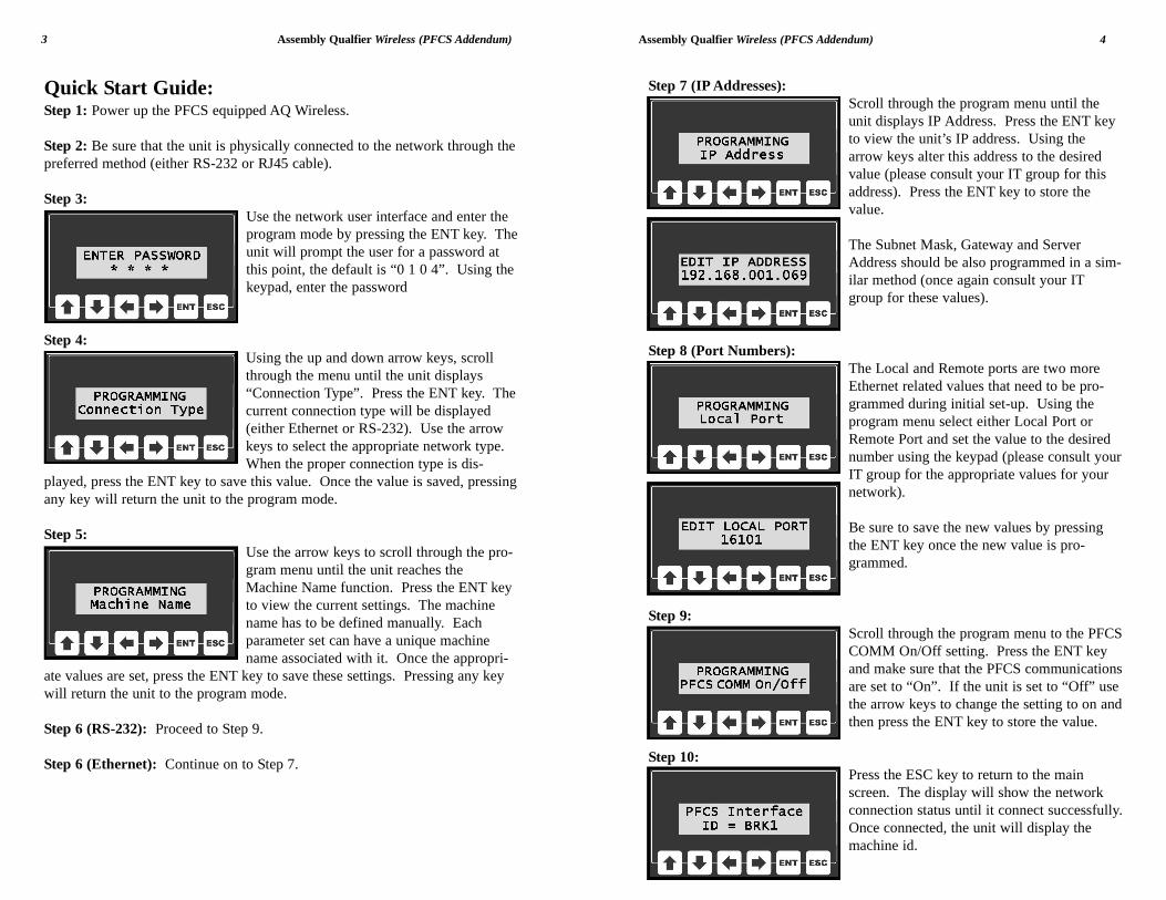
Step 7 (IP Addresses): Scroll through the program menu until theunit displays IP Address. Press the ENT keyto view the unit’s IP address. Using thearrow keys alter this address to the desiredvalue (please consult your IT group for thisaddress). Press the ENT key to store thevalue.
The Subnet Mask, Gateway and ServerAddress should be also programmed in a sim-ilar method (once again consult your ITgroup for these values).
Step 8 (Port Numbers):The Local and Remote ports are two moreEthernet related values that need to be pro-grammed during initial set-up. Using theprogram menu select either Local Port orRemote Port and set the value to the desirednumber using the keypad (please consult yourIT group for the appropriate values for yournetwork).
Be sure to save the new values by pressingthe ENT key once the new value is pro-grammed.
Step 9:Scroll through the program menu to the PFCSCOMM On/Off setting. Press the ENT keyand make sure that the PFCS communicationsare set to “On”. If the unit is set to “Off” usethe arrow keys to change the setting to on andthen press the ENT key to store the value.
Step 10:Press the ESC key to return to the mainscreen. The display will show the networkconnection status until it connect successfully.Once connected, the unit will display themachine id.
Assembly Qualfier Wireless (PFCS Addendum) 4
Quick Start Guide:Step 1: Power up the PFCS equipped AQ Wireless.
Step 2: Be sure that the unit is physically connected to the network through thepreferred method (either RS-232 or RJ45 cable).
Step 3:Use the network user interface and enter theprogram mode by pressing the ENT key. Theunit will prompt the user for a password atthis point, the default is “0 1 0 4”. Using thekeypad, enter the password
Step 4: Using the up and down arrow keys, scrollthrough the menu until the unit displays“Connection Type”. Press the ENT key. Thecurrent connection type will be displayed(either Ethernet or RS-232). Use the arrowkeys to select the appropriate network type.When the proper connection type is dis-
played, press the ENT key to save this value. Once the value is saved, pressingany key will return the unit to the program mode.
Step 5:Use the arrow keys to scroll through the pro-gram menu until the unit reaches theMachine Name function. Press the ENT keyto view the current settings. The machinename has to be defined manually. Eachparameter set can have a unique machinename associated with it. Once the appropri-
ate values are set, press the ENT key to save these settings. Pressing any keywill return the unit to the program mode.
Step 6 (RS-232): Proceed to Step 9.
Step 6 (Ethernet): Continue on to Step 7.
3 Assembly Qualfier Wireless (PFCS Addendum)
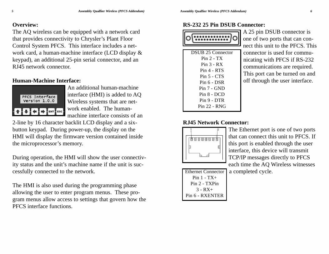
RS-232 25 Pin DSUB Connector:A 25 pin DSUB connector isone of two ports that can con-nect this unit to the PFCS. Thisconnector is used for commu-nicating with PFCS if RS-232communications are required.This port can be turned on andoff through the user interface.
RJ45 Network Connector:The Ethernet port is one of two portsthat can connect this unit to PFCS. Ifthis port is enabled through the userinterface, this device will transmitTCP/IP messages directly to PFCSeach time the AQ Wireless witnessesa completed cycle.
Assembly Qualfier Wireless (PFCS Addendum) 6
Overview:The AQ wireless can be equipped with a network cardthat provides connectivity to Chrysler’s Plant FloorControl System PFCS. This interface includes a net-work card, a human-machine interface (LCD display &keypad), an additional 25-pin serial connector, and anRJ45 network connector.
Human-Machine Interface:An additional human-machineinterface (HMI) is added to AQWireless systems that are net-work enabled. The human-machine interface consists of an
2-line by 16 character backlit LCD display and a six-button keypad. During power-up, the display on theHMI will display the firmware version contained insidethe microprocessor’s memory.
During operation, the HMI will show the user connectiv-ity status and the unit’s machine name if the unit is suc-cessfully connected to the network.
The HMI is also used during the programming phaseallowing the user to enter program menus. These pro-gram menus allow access to settings that govern how thePFCS interface functions.
5 Assembly Qualfier Wireless (PFCS Addendum)
DSUB 25 ConnectorPin 2 - TXPin 3 - RXPin 4 - RTSPin 5 - CTSPin 6 - DSRPin 7 - GNDPin 8 - DCDPin 9 - DTR
Pin 22 - RNG
Ethernet ConnectorPin 1 - TX+
Pin 2 - TXPin3 - RX+
Pin 6 - RXENTER
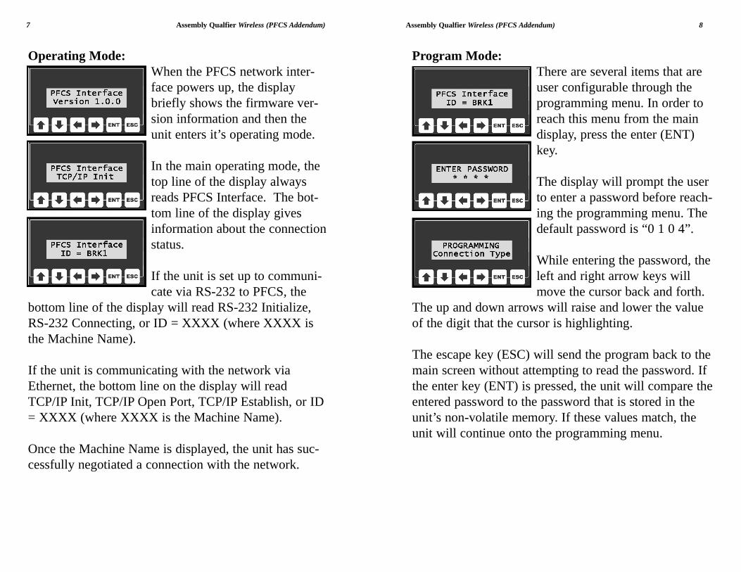
Program Mode:There are several items that areuser configurable through theprogramming menu. In order toreach this menu from the maindisplay, press the enter (ENT)key.
The display will prompt the userto enter a password before reach-ing the programming menu. Thedefault password is “0 1 0 4”.
While entering the password, theleft and right arrow keys willmove the cursor back and forth.
The up and down arrows will raise and lower the valueof the digit that the cursor is highlighting.
The escape key (ESC) will send the program back to themain screen without attempting to read the password. Ifthe enter key (ENT) is pressed, the unit will compare theentered password to the password that is stored in theunit’s non-volatile memory. If these values match, theunit will continue onto the programming menu.
Assembly Qualfier Wireless (PFCS Addendum) 8
Operating Mode:When the PFCS network inter-face powers up, the displaybriefly shows the firmware ver-sion information and then theunit enters it’s operating mode.
In the main operating mode, thetop line of the display alwaysreads PFCS Interface. The bot-tom line of the display givesinformation about the connectionstatus.
If the unit is set up to communi-cate via RS-232 to PFCS, the
bottom line of the display will read RS-232 Initialize,RS-232 Connecting, or ID = XXXX (where XXXX isthe Machine Name).
If the unit is communicating with the network viaEthernet, the bottom line on the display will readTCP/IP Init, TCP/IP Open Port, TCP/IP Establish, or ID= XXXX (where XXXX is the Machine Name).
Once the Machine Name is displayed, the unit has suc-cessfully negotiated a connection with the network.
7 Assembly Qualfier Wireless (PFCS Addendum)
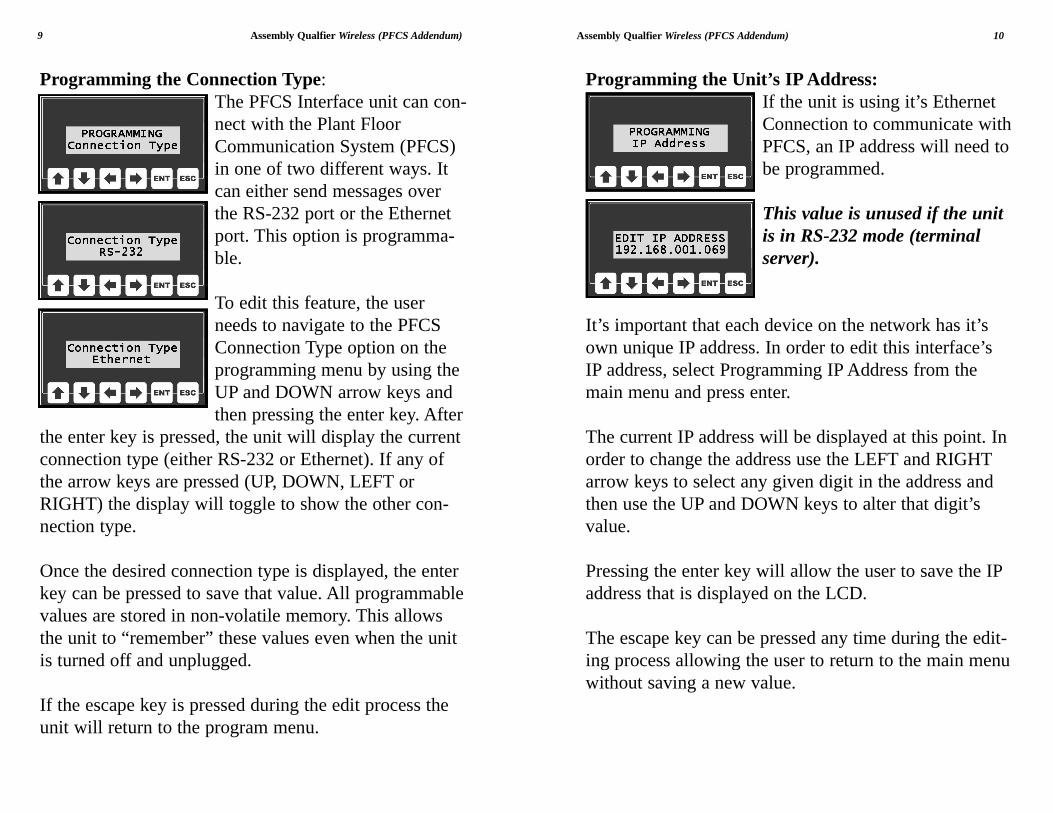
Programming the Unit’s IP Address:If the unit is using it’s EthernetConnection to communicate withPFCS, an IP address will need tobe programmed.
This value is unused if the unitis in RS-232 mode (terminalserver).
It’s important that each device on the network has it’sown unique IP address. In order to edit this interface’sIP address, select Programming IP Address from themain menu and press enter.
The current IP address will be displayed at this point. Inorder to change the address use the LEFT and RIGHTarrow keys to select any given digit in the address andthen use the UP and DOWN keys to alter that digit’svalue.
Pressing the enter key will allow the user to save the IPaddress that is displayed on the LCD.
The escape key can be pressed any time during the edit-ing process allowing the user to return to the main menuwithout saving a new value.
Assembly Qualfier Wireless (PFCS Addendum) 10
Programming the Connection Type:The PFCS Interface unit can con-nect with the Plant FloorCommunication System (PFCS)in one of two different ways. Itcan either send messages overthe RS-232 port or the Ethernetport. This option is programma-ble.
To edit this feature, the userneeds to navigate to the PFCSConnection Type option on theprogramming menu by using theUP and DOWN arrow keys andthen pressing the enter key. After
the enter key is pressed, the unit will display the currentconnection type (either RS-232 or Ethernet). If any ofthe arrow keys are pressed (UP, DOWN, LEFT orRIGHT) the display will toggle to show the other con-nection type.
Once the desired connection type is displayed, the enterkey can be pressed to save that value. All programmablevalues are stored in non-volatile memory. This allowsthe unit to “remember” these values even when the unitis turned off and unplugged.
If the escape key is pressed during the edit process theunit will return to the program menu.
9 Assembly Qualfier Wireless (PFCS Addendum)
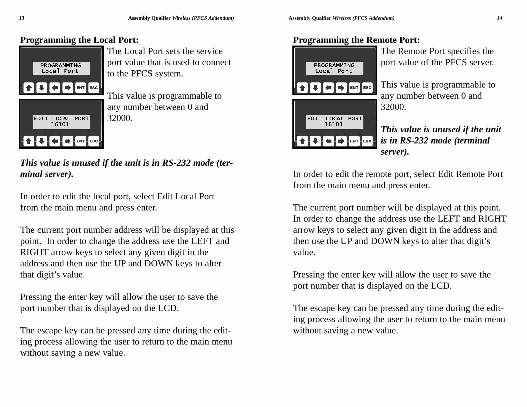
Programming the Gateway:Gateways perform routing func-tions. This gateway value identi-fies the router that connects aLAN to other networks. Somegateways also perform protocolconversions.
This value is unused if the unitis in RS-232 mode (terminalserver).
In order to edit this gateway’s IP address, selectGateway from the main menu and press enter.
The current gateway address will be displayed at thispoint. In order to change the address use the LEFT andRIGHT arrow keys to select any given digit in theaddress and then use the UP and DOWN keys to alterthat digit’s value.
Pressing the enter key will allow the user to save thegateway’s IP address that is displayed on the LCD.
The escape key can be pressed any time during the edit-ing process allowing the user to return to the main menuwithout saving a new value.
Assembly Qualfier Wireless (PFCS Addendum) 12
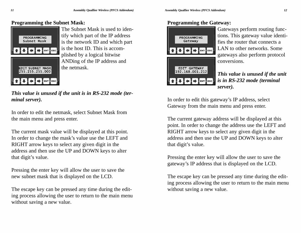
Programming the Subnet Mask:The Subnet Mask is used to iden-tify which part of the IP addressis the network ID and which partis the host ID. This is accom-plished by a logical bitwiseANDing of the IP address andthe netmask.
This value is unused if the unit is in RS-232 mode (ter-minal server).
In order to edit the netmask, select Subnet Mask fromthe main menu and press enter.
The current mask value will be displayed at this point.In order to change the mask’s value use the LEFT andRIGHT arrow keys to select any given digit in theaddress and then use the UP and DOWN keys to alterthat digit’s value.
Pressing the enter key will allow the user to save thenew subnet mask that is displayed on the LCD.
The escape key can be pressed any time during the edit-ing process allowing the user to return to the main menuwithout saving a new value.
11 Assembly Qualfier Wireless (PFCS Addendum)
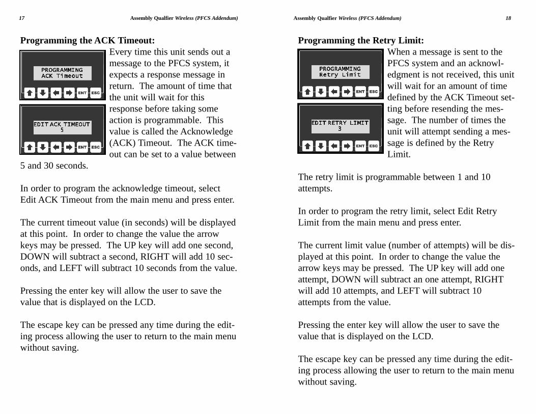
Programming the Remote Port:The Remote Port specifies theport value of the PFCS server.
This value is programmable toany number between 0 and32000.
This value is unused if the unitis in RS-232 mode (terminalserver).
In order to edit the remote port, select Edit Remote Portfrom the main menu and press enter.
The current port number will be displayed at this point.In order to change the address use the LEFT and RIGHTarrow keys to select any given digit in the address andthen use the UP and DOWN keys to alter that digit’svalue.
Pressing the enter key will allow the user to save theport number that is displayed on the LCD.
The escape key can be pressed any time during the edit-ing process allowing the user to return to the main menuwithout saving a new value.
Assembly Qualfier Wireless (PFCS Addendum) 14
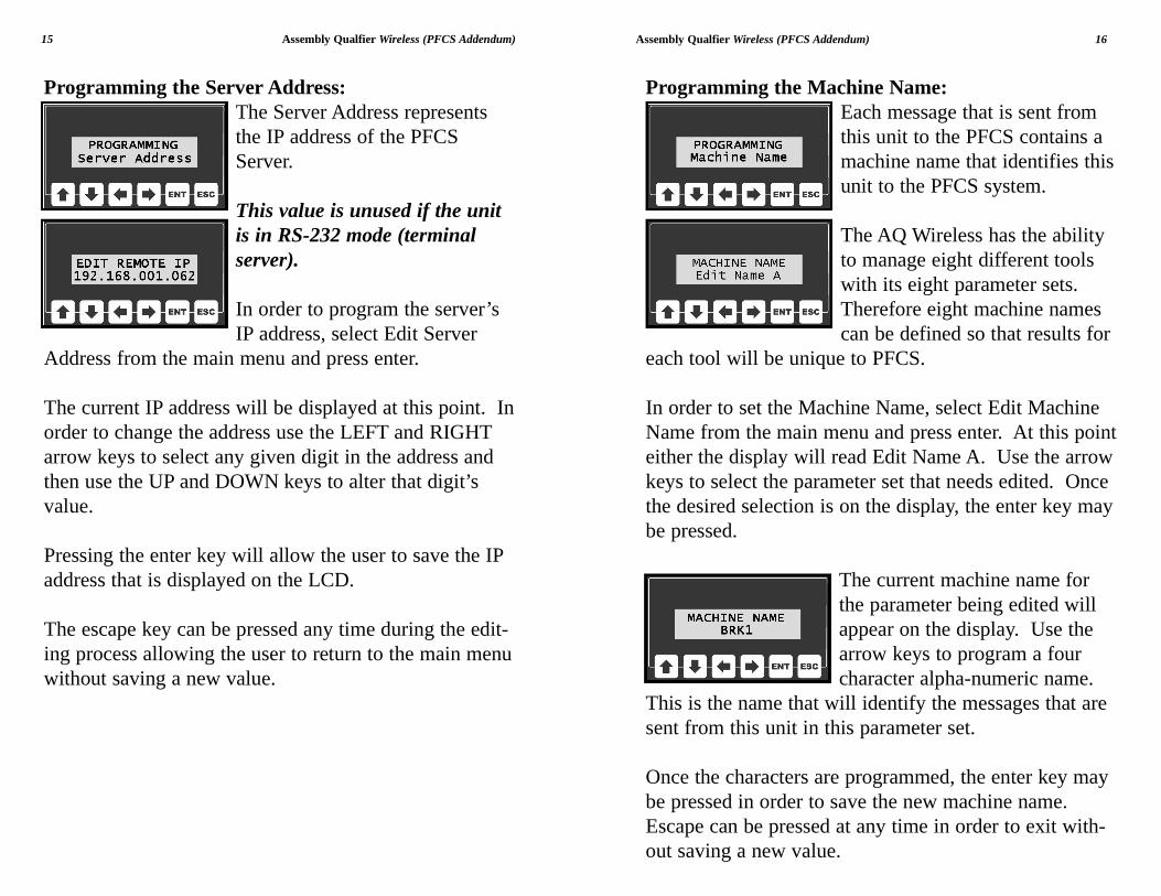
Programming the Local Port:The Local Port sets the serviceport value that is used to connectto the PFCS system.
This value is programmable toany number between 0 and32000.
This value is unused if the unit is in RS-232 mode (ter-minal server).
In order to edit the local port, select Edit Local Portfrom the main menu and press enter.
The current port number address will be displayed at thispoint. In order to change the address use the LEFT andRIGHT arrow keys to select any given digit in theaddress and then use the UP and DOWN keys to alterthat digit’s value.
Pressing the enter key will allow the user to save theport number that is displayed on the LCD.
The escape key can be pressed any time during the edit-ing process allowing the user to return to the main menuwithout saving a new value.
13 Assembly Qualfier Wireless (PFCS Addendum)
Programming the Machine Name:Each message that is sent fromthis unit to the PFCS contains amachine name that identifies thisunit to the PFCS system.
The AQ Wireless has the abilityto manage eight different toolswith its eight parameter sets.Therefore eight machine namescan be defined so that results for
each tool will be unique to PFCS.
In order to set the Machine Name, select Edit MachineName from the main menu and press enter. At this pointeither the display will read Edit Name A. Use the arrowkeys to select the parameter set that needs edited. Oncethe desired selection is on the display, the enter key maybe pressed.
The current machine name forthe parameter being edited willappear on the display. Use thearrow keys to program a fourcharacter alpha-numeric name.
This is the name that will identify the messages that aresent from this unit in this parameter set.
Once the characters are programmed, the enter key maybe pressed in order to save the new machine name.Escape can be pressed at any time in order to exit with-out saving a new value.
Assembly Qualfier Wireless (PFCS Addendum) 16
Programming the Server Address:The Server Address representsthe IP address of the PFCSServer.
This value is unused if the unitis in RS-232 mode (terminalserver).
In order to program the server’sIP address, select Edit Server
Address from the main menu and press enter.
The current IP address will be displayed at this point. Inorder to change the address use the LEFT and RIGHTarrow keys to select any given digit in the address andthen use the UP and DOWN keys to alter that digit’svalue.
Pressing the enter key will allow the user to save the IPaddress that is displayed on the LCD.
The escape key can be pressed any time during the edit-ing process allowing the user to return to the main menuwithout saving a new value.
15 Assembly Qualfier Wireless (PFCS Addendum)
Programming the Retry Limit:When a message is sent to thePFCS system and an acknowl-edgment is not received, this unitwill wait for an amount of timedefined by the ACK Timeout set-ting before resending the mes-sage. The number of times theunit will attempt sending a mes-sage is defined by the RetryLimit.
The retry limit is programmable between 1 and 10attempts.
In order to program the retry limit, select Edit RetryLimit from the main menu and press enter.
The current limit value (number of attempts) will be dis-played at this point. In order to change the value thearrow keys may be pressed. The UP key will add oneattempt, DOWN will subtract an one attempt, RIGHTwill add 10 attempts, and LEFT will subtract 10attempts from the value.
Pressing the enter key will allow the user to save thevalue that is displayed on the LCD.
The escape key can be pressed any time during the edit-ing process allowing the user to return to the main menuwithout saving.
Assembly Qualfier Wireless (PFCS Addendum) 18
Programming the ACK Timeout:Every time this unit sends out amessage to the PFCS system, itexpects a response message inreturn. The amount of time thatthe unit will wait for thisresponse before taking someaction is programmable. Thisvalue is called the Acknowledge(ACK) Timeout. The ACK time-out can be set to a value between
5 and 30 seconds.
In order to program the acknowledge timeout, selectEdit ACK Timeout from the main menu and press enter.
The current timeout value (in seconds) will be displayedat this point. In order to change the value the arrowkeys may be pressed. The UP key will add one second,DOWN will subtract a second, RIGHT will add 10 sec-onds, and LEFT will subtract 10 seconds from the value.
Pressing the enter key will allow the user to save thevalue that is displayed on the LCD.
The escape key can be pressed any time during the edit-ing process allowing the user to return to the main menuwithout saving.
17 Assembly Qualfier Wireless (PFCS Addendum)
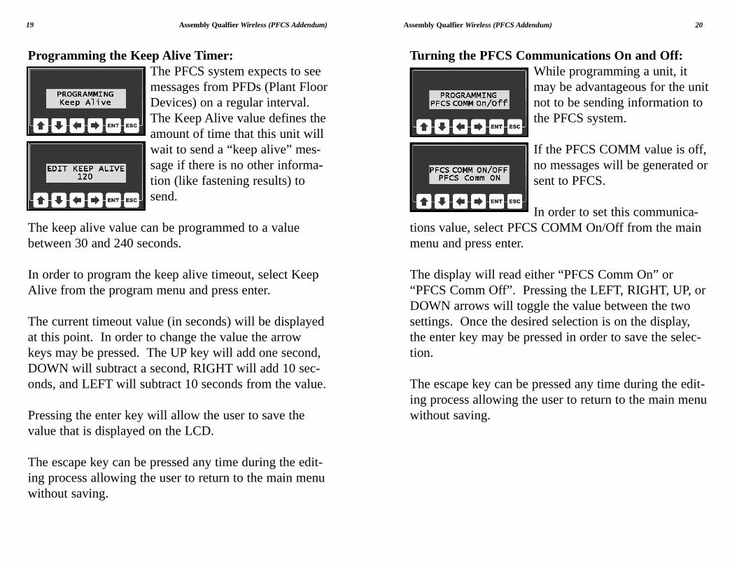
Turning the PFCS Communications On and Off:While programming a unit, itmay be advantageous for the unitnot to be sending information tothe PFCS system.
If the PFCS COMM value is off,no messages will be generated orsent to PFCS.
In order to set this communica-tions value, select PFCS COMM On/Off from the mainmenu and press enter.
The display will read either “PFCS Comm On” or“PFCS Comm Off”. Pressing the LEFT, RIGHT, UP, orDOWN arrows will toggle the value between the twosettings. Once the desired selection is on the display,the enter key may be pressed in order to save the selec-tion.
The escape key can be pressed any time during the edit-ing process allowing the user to return to the main menuwithout saving.
Assembly Qualfier Wireless (PFCS Addendum) 20
Programming the Keep Alive Timer:The PFCS system expects to seemessages from PFDs (Plant FloorDevices) on a regular interval.The Keep Alive value defines theamount of time that this unit willwait to send a “keep alive” mes-sage if there is no other informa-tion (like fastening results) tosend.
The keep alive value can be programmed to a valuebetween 30 and 240 seconds.
In order to program the keep alive timeout, select KeepAlive from the program menu and press enter.
The current timeout value (in seconds) will be displayedat this point. In order to change the value the arrowkeys may be pressed. The UP key will add one second,DOWN will subtract a second, RIGHT will add 10 sec-onds, and LEFT will subtract 10 seconds from the value.
Pressing the enter key will allow the user to save thevalue that is displayed on the LCD.
The escape key can be pressed any time during the edit-ing process allowing the user to return to the main menuwithout saving.
19 Assembly Qualfier Wireless (PFCS Addendum)
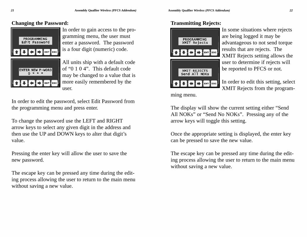
Transmitting Rejects:In some situations where rejectsare being logged it may beadvantageous to not send torqueresults that are rejects. TheXMIT Rejects setting allows theuser to determine if rejects willbe reported to PFCS or not.
In order to edit this setting, selectXMIT Rejects from the program-
ming menu.
The display will show the current setting either “SendAll NOKs” or “Send No NOKs”. Pressing any of thearrow keys will toggle this setting.
Once the appropriate setting is displayed, the enter keycan be pressed to save the new value.
The escape key can be pressed any time during the edit-ing process allowing the user to return to the main menuwithout saving a new value.
Assembly Qualfier Wireless (PFCS Addendum) 22
Changing the Password:In order to gain access to the pro-gramming menu, the user mustenter a password. The passwordis a four digit (numeric) code.
All units ship with a default codeof “0 1 0 4”. This default codemay be changed to a value that ismore easily remembered by theuser.
In order to edit the password, select Edit Password fromthe programming menu and press enter.
To change the password use the LEFT and RIGHTarrow keys to select any given digit in the address andthen use the UP and DOWN keys to alter that digit’svalue.
Pressing the enter key will allow the user to save thenew password.
The escape key can be pressed any time during the edit-ing process allowing the user to return to the main menuwithout saving a new value.
21 Assembly Qualfier Wireless (PFCS Addendum)
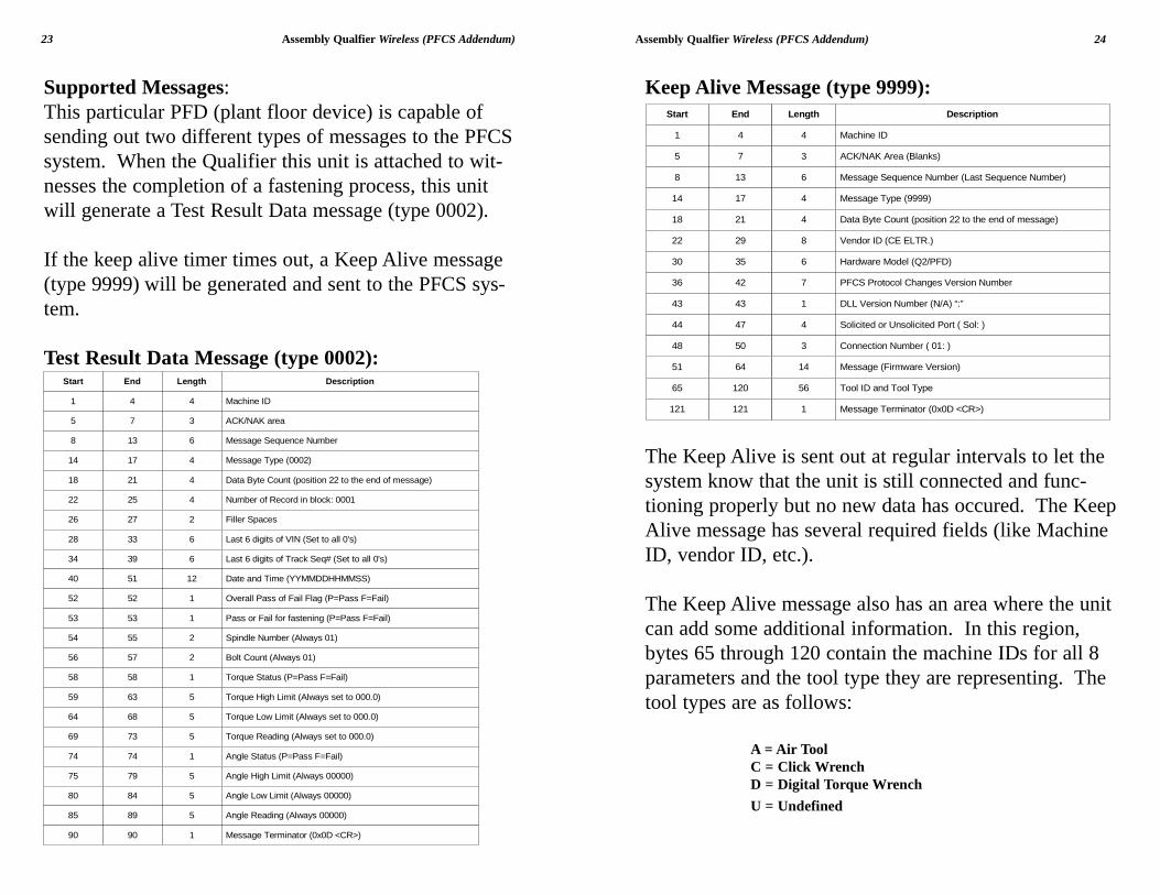
Keep Alive Message (type 9999):
The Keep Alive is sent out at regular intervals to let thesystem know that the unit is still connected and func-tioning properly but no new data has occured. The KeepAlive message has several required fields (like MachineID, vendor ID, etc.).
The Keep Alive message also has an area where the unitcan add some additional information. In this region,bytes 65 through 120 contain the machine IDs for all 8parameters and the tool type they are representing. Thetool types are as follows:
A = Air ToolC = Click WrenchD = Digital Torque WrenchU = Undefined
Assembly Qualfier Wireless (PFCS Addendum) 24
Supported Messages:This particular PFD (plant floor device) is capable ofsending out two different types of messages to the PFCSsystem. When the Qualifier this unit is attached to wit-nesses the completion of a fastening process, this unitwill generate a Test Result Data message (type 0002).
If the keep alive timer times out, a Keep Alive message(type 9999) will be generated and sent to the PFCS sys-tem.
Test Result Data Message (type 0002):
23 Assembly Qualfier Wireless (PFCS Addendum)
Start End Length Description
1 4 4 Machine ID
5 7 3 ACK/NAK area
8 13 6 Message Sequence Number
14 17 4 Message Type (0002)
18 21 4 Data Byte Count (position 22 to the end of message)
22 25 4 Number of Record in block: 0001
26 27 2 Filler Spaces
28 33 6 Last 6 digits of VIN (Set to all 0's)
34 39 6 Last 6 digits of Track Seq# (Set to all 0's)
40 51 12 Date and Time (YYMMDDHHMMSS)
52 52 1 Overall Pass of Fail Flag (P=Pass F=Fail)
53 53 1 Pass or Fail for fastening (P=Pass F=Fail)
54 55 2 Spindle Number (Always 01)
56 57 2 Bolt Count (Always 01)
58 58 1 Torque Status (P=Pass F=Fail)
59 63 5 Torque High Limit (Always set to 000.0)
64 68 5 Torque Low Limit (Always set to 000.0)
69 73 5 Torque Reading (Always set to 000.0)
74 74 1 Angle Status (P=Pass F=Fail)
75 79 5 Angle High Limit (Always 00000)
80 84 5 Angle Low Limit (Always 00000)
85 89 5 Angle Reading (Always 00000)
90 90 1 Message Terminator (0x0D <CR>)
Start End Length Description
1 4 4 Machine ID
5 7 3 ACK/NAK Area (Blanks)
8 13 6 Message Sequence Number (Last Sequence Number)
14 17 4 Message Type (9999)
18 21 4 Data Byte Count (position 22 to the end of message)
22 29 8 Vendor ID (CE ELTR.)
36 42 7 PFCS Protocol Changes Version Number
51 64 14 Message (Firmware Version)
65 120 56 Tool ID and Tool Type
30 35 6 Hardware Model (Q2/PFD)
43 43 1 DLL Version Number (N/A) “:”
44 47 4 Solicited or Unsolicited Port ( Sol: )
48 50 3 Connection Number ( 01: )
121 121 1 Message Terminator (0x0D <CR>)