Embed Size (px)
Citation preview
23
Chapter 5
Plant design and construction
5.1 GENERAL PLANT CONSIDERATIONS . . . . . . . . . . . . . . . . . . . . . . . . . . . . . . . . . . . . . . . . . . . . . . . 23
5.2 DEPURATION TANk DESIGN AND CONSTRUCTION . . . . . . . . . . . . . . . . . . . . . . . . . . . . . . 25
5.3 TRAyS/BASkETS FOR DEPURATION . . . . . . . . . . . . . . . . . . . . . . . . . . . . . . . . . . . . . . . . . . . . . . . 26
5.4 PLUmBING AND WATER FLOW ARRANGEmENTS . . . . . . . . . . . . . . . . . . . . . . . . . . . . . . . 28
5.5 DISCHARGE OF USED SEAWATER . . . . . . . . . . . . . . . . . . . . . . . . . . . . . . . . . . . . . . . . . . . . . . . . . . 31
5.1 general plant considerations
Plants should be constructed in such a way as to prevent stored raw material, the depuration systems, depurated and packaged product, and associated processes, from contamination from airborne or pest-borne contamination and should not be subject to flooding. Preferably, the systems themselves, and associated processes, should be sited within buildings in order to aid control of temperature and contamination. Where this is not possible, systems should be covered during operation and procedures put in place to protect pre- and post-depuration shellfish from contamination and extremes of temperature and exposure to direct sunlight.
Internal surfaces should be made of materials that are easily cleaned and of materials that will not be affected by the use of appropriate disinfectants. In the United States of America, the NSF White Book® Listing has replaced the now terminated US Department of Agriculture (USDA) Listing of Proprietary Substances and Nonfood Compounds. Registered products are listed on the NSF Web site (www.nsf.org/usda/psnclistings.asp).
Floors should be made of easily cleanable material and should slope towards drainage points. Windows and doors should be constructed so as to prevent access of birds and animals.
The product flow should be from dirty to clean going through the steps below in sequence:
1. Receipt of harvested product (through its own door) 2. Indoor pre-depuration storage 3. Washing, debyssing (for mussels) and culling 4. Into depuration tank 5. Depuration 6. Out of depuration tank 7. Washing (may be undertaken in tank as long as the shellfish are not
reimmersed) 8. Culling 9. Grading (if necessary) and packing 10. Dispatch of finished product
Bivalve depuration: fundamental and practical aspects24
Product flow charts from harvest to distribution are given in Appendix 1.
It is strongly recommended that the area used for grading and packing of washed and culled depurated product be physically separated from the rest of the plant by a wall and doorway.
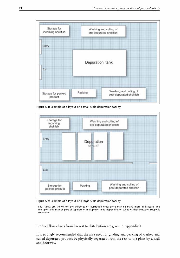
Figure 5.1: Example of a layout of a small-scale depuration facility
Figure 5.2: Example of a layout of a large-scale depuration facility
1 Four tanks are shown for the purposes of illustration only: there may be many more in practice. The multiple tanks may be part of separate or multiple systems (depending on whether their seawater supply is common).
Chapter 5 – General principles of depuration 25
Areas for staff, such as rest rooms and toilets, together with office space, should also be physically separated from the processing area.
While adequate lighting is necessary for the health and safety of staff, the lighting in the vicinity of the tanks themselves should be subdued during the depuration cycle as the animals will not function properly in bright light conditions.
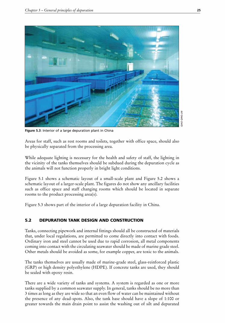
Figure 5.1 shows a schematic layout of a small-scale plant and Figure 5.2 shows a schematic layout of a larger-scale plant. The figures do not show any ancillary facilities such as office space and staff changing rooms which should be located in separate rooms to the product processing area(s). Figure 5.3 shows part of the interior of a large depuration facility in China.
5.2 depuration tank design and construction
Tanks, connecting pipework and internal fittings should all be constructed of materials that, under local regulations, are permitted to come directly into contact with foods. Ordinary iron and steel cannot be used due to rapid corrosion, all metal components coming into contact with the circulating seawater should be made of marine grade steel. Other metals should be avoided as some, for example copper, are toxic to the animals.
The tanks themselves are usually made of marine-grade steel, glass-reinforced plastic (GRP) or high density polyethylene (HDPE). If concrete tanks are used, they should be sealed with epoxy resin.
There are a wide variety of tanks and systems. A system is regarded as one or more tanks supplied by a common seawater supply. In general, tanks should be no more than 3 times as long as they are wide so that an even flow of water can be maintained without the presence of any dead-spots. Also, the tank base should have a slope of 1:100 or greater towards the main drain point to assist the washing out of silt and depurated
Figure 5.3: Interior of a large depuration plant in China
qIA
O q
Ing
-lIn
Bivalve depuration: fundamental and practical aspects26
material after draining at the end of the depuration cycle. It is preferable to have a large bore drain in the tank for final flushing after the depuration cycle that is separate to
the normal outlet used during depuration and draining down.
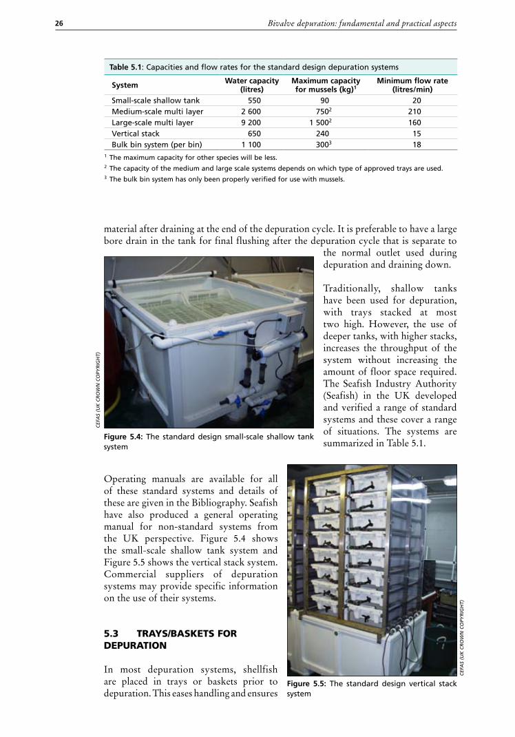
Traditionally, shallow tanks have been used for depuration, with trays stacked at most two high. However, the use of deeper tanks, with higher stacks, increases the throughput of the system without increasing the amount of floor space required. The Seafish Industry Authority (Seafish) in the UK developed and verified a range of standard systems and these cover a range of situations. The systems are summarized in Table 5.1.
Operating manuals are available for all of these standard systems and details of these are given in the Bibliography. Seafish have also produced a general operating manual for non-standard systems from the UK perspective. Figure 5.4 shows the small-scale shallow tank system and Figure 5.5 shows the vertical stack system. Commercial suppliers of depuration systems may provide specific information on the use of their systems.
5.3 trays/Baskets for depuration
In most depuration systems, shellfish are placed in trays or baskets prior to depuration. This eases handling and ensures
Table 5.1: Capacities and flow rates for the standard design depuration systems
System Water capacity (litres)
maximum capacity for mussels (kg)1
minimum flow rate (litres/min)
Small-scale shallow tank 550 90 20Medium-scale multi layer 2 600 7502 210Large-scale multi layer 9 200 1 5002 160Vertical stack 650 240 15Bulk bin system (per bin) 1 100 3003 18
1 The maximum capacity for other species will be less.2 The capacity of the medium and large scale systems depends on which type of approved trays are used.3 The bulk bin system has only been properly verified for use with mussels.
CEF
As
(uK
CR
Ow
n C
OPy
RIg
hT)
Figure 5.4: The standard design small-scale shallow tank system
Figure 5.5: The standard design vertical stack system
CEF
As
(uK
CR
Ow
n C
OPy
RIg
hT)
Chapter 5 – General principles of depuration 27
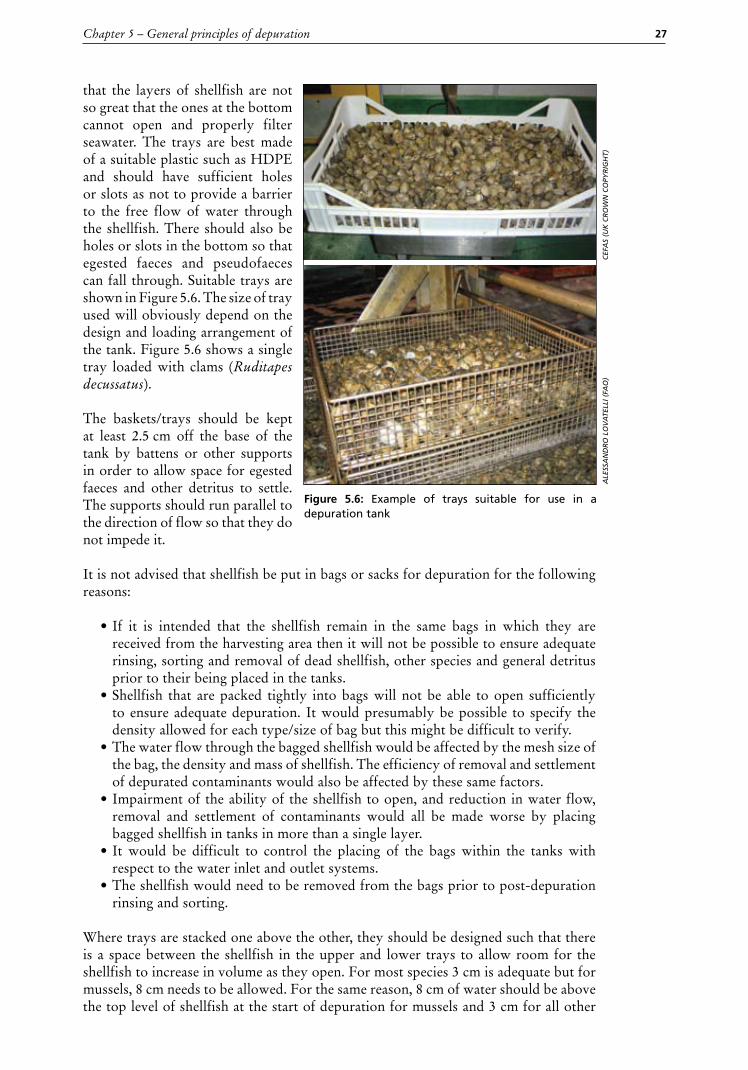
that the layers of shellfish are not so great that the ones at the bottom cannot open and properly filter seawater. The trays are best made of a suitable plastic such as HDPE and should have sufficient holes or slots as not to provide a barrier to the free flow of water through the shellfish. There should also be holes or slots in the bottom so that egested faeces and pseudofaeces can fall through. Suitable trays are shown in Figure 5.6. The size of tray used will obviously depend on the design and loading arrangement of the tank. Figure 5.6 shows a single tray loaded with clams (Ruditapes decussatus).
The baskets/trays should be kept at least 2.5 cm off the base of the tank by battens or other supports in order to allow space for egested faeces and other detritus to settle. The supports should run parallel to the direction of flow so that they do not impede it.
It is not advised that shellfish be put in bags or sacks for depuration for the following reasons:
• If it is intended that the shellfish remain in the same bags in which they are received from the harvesting area then it will not be possible to ensure adequate rinsing, sorting and removal of dead shellfish, other species and general detritus prior to their being placed in the tanks.
• Shellfish that are packed tightly into bags will not be able to open sufficiently to ensure adequate depuration. It would presumably be possible to specify the density allowed for each type/size of bag but this might be difficult to verify.
• The water flow through the bagged shellfish would be affected by the mesh size of the bag, the density and mass of shellfish. The efficiency of removal and settlement of depurated contaminants would also be affected by these same factors.
• Impairment of the ability of the shellfish to open, and reduction in water flow, removal and settlement of contaminants would all be made worse by placing bagged shellfish in tanks in more than a single layer.
• It would be difficult to control the placing of the bags within the tanks with respect to the water inlet and outlet systems.
• The shellfish would need to be removed from the bags prior to post-depuration rinsing and sorting.
Where trays are stacked one above the other, they should be designed such that there is a space between the shellfish in the upper and lower trays to allow room for the shellfish to increase in volume as they open. For most species 3 cm is adequate but for mussels, 8 cm needs to be allowed. For the same reason, 8 cm of water should be above the top level of shellfish at the start of depuration for mussels and 3 cm for all other
CEF
As
(uK
CR
Ow
n C
OPy
RIg
hT)
AlE
ssA
nd
RO
lO
vA
TEll
I (FA
O)
Figure 5.6: Example of trays suitable for use in a depuration tank
Bivalve depuration: fundamental and practical aspects28
species. It is important that the shellfish are covered by water at all times otherwise they will not depurate.
The bulk bin system developed in the UK allows depuration of mussels in 38 cm deep layers with sufficient aeration being provided by a high flow rate of water downwards through the shellfish. The system has not been verified for other species and there are concerns that animals of other species may not be able to open, and therefore function, properly at the bottom of such a load of other shellfish above. In some countries, deeper systems have been used for mussels but there is no direct evidence that the individuals at the very bottom are able to open and there have also been problems in maintaining sufficient dissolved oxygen within the system.
5.4 plumBing and Water floW arrangements
A single system may consist of several tanks with a common water source (flow-through, recirculation or static). If there is more than one tank then the water should be supplied to all tanks in parallel, rather than sequentially, in order to prevent contaminants from one tank passing to another. The requirements for batch operation applies to the water as well as the shellfish and recirculation systems containing more than one tank connected to the same water supply must be started and stopped at the same time – the shellfish in all of the interconnected tanks form a single batch operation.
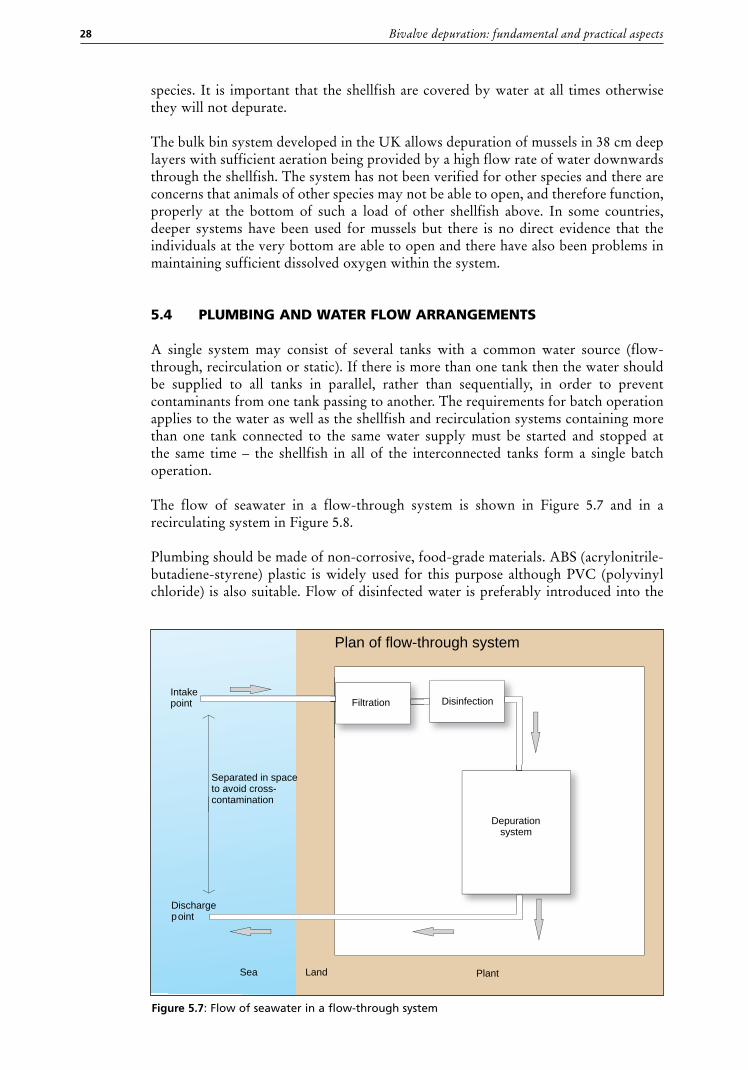
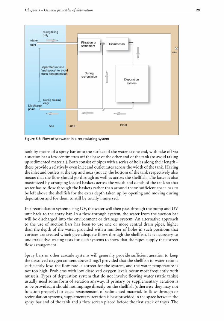
The flow of seawater in a flow-through system is shown in Figure 5.7 and in a recirculating system in Figure 5.8.
Plumbing should be made of non-corrosive, food-grade materials. ABS (acrylonitrile-butadiene-styrene) plastic is widely used for this purpose although PVC (polyvinyl chloride) is also suitable. Flow of disinfected water is preferably introduced into the
Intakepoint
Dischargepoint
Separated in spaceto avoid cross-contamination
Filtration Disinfection
Depurationsystem
PlantLandSea
Plan of flow-through system
Figure 5.7: Flow of seawater in a flow-through system
Chapter 5 – General principles of depuration 29
tank by means of a spray bar onto the surface of the water at one end, with take off via a suction bar a few centimetres off the base of the other end of the tank (to avoid taking up sedimented material). Both consist of pipes with a series of holes along their length – these provide a relatively even inlet and outlet rates across the width of the tank. Having the inlet and outlets at the top and near (not at) the bottom of the tank respectively also means that the flow should go through as well as across the shellfish. The latter is also maximized by arranging loaded baskets across the width and depth of the tank so that water has to flow through the baskets rather than around them: sufficient space has to be left above the shellfish for the extra depth taken up by opening and moving during depuration and for them to still be totally immersed.
In a recirculation system using UV, the water will then pass through the pump and UV unit back to the spray bar. In a flow-through system, the water from the suction bar will be discharged into the environment or drainage system. An alternative approach to the use of suction bars has been to use one or more central drain pipes, higher than the depth of the water, provided with a number of holes in such positions that vortices are created which give adequate flows through the shellfish. It is necessary to undertake dye-tracing tests for such systems to show that the pipes supply the correct flow arrangement.
Spray bars or other cascade systems will generally provide sufficient aeration to keep the dissolved oxygen content above 5 mg/l provided that the shellfish to water ratio is sufficiently low, the flow rate is correct for the system, and the water temperature is not too high. Problems with low dissolved oxygen levels occur most frequently with mussels. Types of depuration system that do not involve flowing water (static tanks) usually need some form of aeration anyway. If primary or supplementary aeration is to be provided, it should not impinge directly on the shellfish (otherwise they may not function properly) or cause resuspension of sedimented material. In flow-through or recirculation systems, supplementary aeration is best provided in the space between the spray bar end of the tank and a flow screen placed before the first stack of trays. The
Intake
point
Dischargepoint
Separated in time (and space) to avoid cross-contamination
PlantLandSea
During filling only
During draining only
Duringrecirculation
Valve
Filtration or settlement
Disinfection
Depuration
system
Figure 5.8: Flow of seawater in a recirculating system
Bivalve depuration: fundamental and practical aspects30
flow screen consists of a vertical sheet of material (plastic or stainless steel, provided with a number of holes in a regular pattern. In the larger UK standard design tanks, flow screens are placed at either end of the tank in order to help provide an even lateral flow of water.
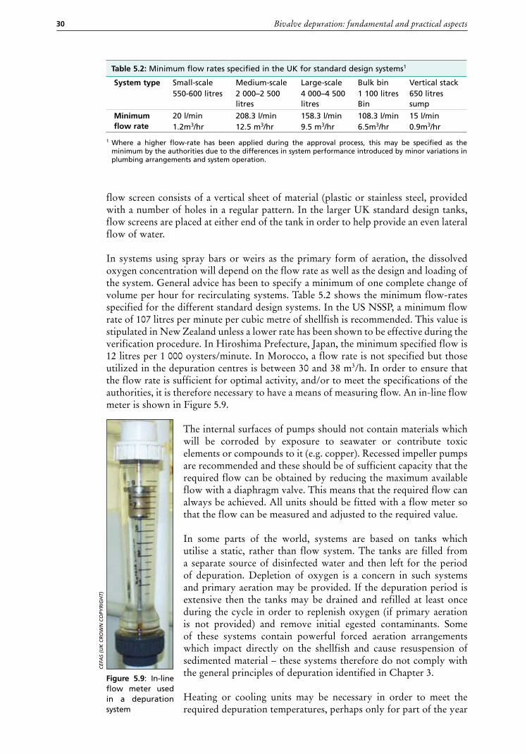
In systems using spray bars or weirs as the primary form of aeration, the dissolved oxygen concentration will depend on the flow rate as well as the design and loading of the system. General advice has been to specify a minimum of one complete change of volume per hour for recirculating systems. Table 5.2 shows the minimum flow-rates specified for the different standard design systems. In the US NSSP, a minimum flow rate of 107 litres per minute per cubic metre of shellfish is recommended. This value is stipulated in New Zealand unless a lower rate has been shown to be effective during the verification procedure. In Hiroshima Prefecture, Japan, the minimum specified flow is 12 litres per 1 000 oysters/minute. In Morocco, a flow rate is not specified but those utilized in the depuration centres is between 30 and 38 m3/h. In order to ensure that the flow rate is sufficient for optimal activity, and/or to meet the specifications of the authorities, it is therefore necessary to have a means of measuring flow. An in-line flow meter is shown in Figure 5.9.
The internal surfaces of pumps should not contain materials which will be corroded by exposure to seawater or contribute toxic elements or compounds to it (e.g. copper). Recessed impeller pumps are recommended and these should be of sufficient capacity that the required flow can be obtained by reducing the maximum available flow with a diaphragm valve. This means that the required flow can always be achieved. All units should be fitted with a flow meter so that the flow can be measured and adjusted to the required value.
In some parts of the world, systems are based on tanks which utilise a static, rather than flow system. The tanks are filled from a separate source of disinfected water and then left for the period of depuration. Depletion of oxygen is a concern in such systems and primary aeration may be provided. If the depuration period is extensive then the tanks may be drained and refilled at least once during the cycle in order to replenish oxygen (if primary aeration is not provided) and remove initial egested contaminants. Some of these systems contain powerful forced aeration arrangements which impact directly on the shellfish and cause resuspension of sedimented material – these systems therefore do not comply with the general principles of depuration identified in Chapter 3.
Heating or cooling units may be necessary in order to meet the required depuration temperatures, perhaps only for part of the year
Figure 5.9: In-line flow meter used in a depuration system
CEF
As
(uK
CR
Ow
n C
OPy
RIg
hT)
Table 5.2: Minimum flow rates specified in the UK for standard design systems1
System type Small-scale550-600 litres
Medium-scale2 000–2 500 litres
Large-scale4 000–4 500 litres
Bulk bin1 100 litres Bin
Vertical stack650 litres sump
minimum flow rate
20 l/min1.2m3/hr
208.3 l/min12.5 m3/hr
158.3 l/min9.5 m3/hr
108.3 l/min6.5m3/hr
15 l/min 0.9m3/hr
1 Where a higher flow-rate has been applied during the approval process, this may be specified as the minimum by the authorities due to the differences in system performance introduced by minor variations in plumbing arrangements and system operation.
Chapter 5 – General principles of depuration 31
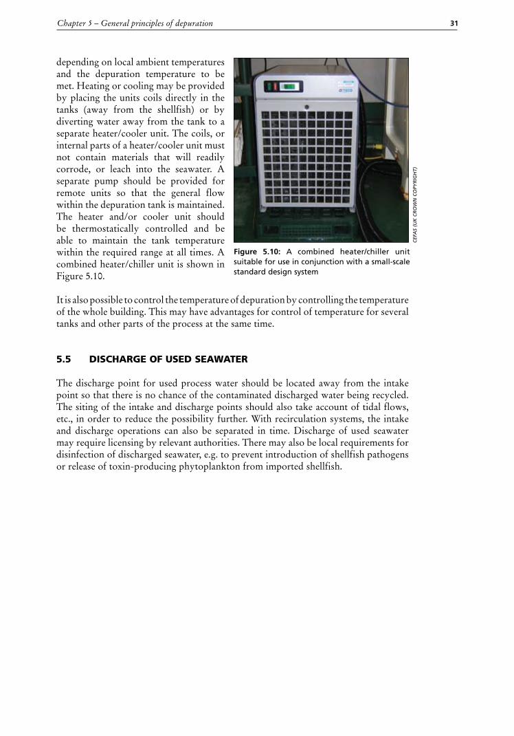
depending on local ambient temperatures and the depuration temperature to be met. Heating or cooling may be provided by placing the units coils directly in the tanks (away from the shellfish) or by diverting water away from the tank to a separate heater/cooler unit. The coils, or internal parts of a heater/cooler unit must not contain materials that will readily corrode, or leach into the seawater. A separate pump should be provided for remote units so that the general flow within the depuration tank is maintained. The heater and/or cooler unit should be thermostatically controlled and be able to maintain the tank temperature within the required range at all times. A combined heater/chiller unit is shown in Figure 5.10. It is also possible to control the temperature of depuration by controlling the temperature of the whole building. This may have advantages for control of temperature for several tanks and other parts of the process at the same time.
5.5 discharge of used seaWater
The discharge point for used process water should be located away from the intake point so that there is no chance of the contaminated discharged water being recycled. The siting of the intake and discharge points should also take account of tidal flows, etc., in order to reduce the possibility further. With recirculation systems, the intake and discharge operations can also be separated in time. Discharge of used seawater may require licensing by relevant authorities. There may also be local requirements for disinfection of discharged seawater, e.g. to prevent introduction of shellfish pathogens or release of toxin-producing phytoplankton from imported shellfish.
Figure 5.10: A combined heater/chiller unit suitable for use in conjunction with a small-scale standard design system
CEF
As
(uK
CR
Ow
n C
OPy
RIg
hT)

33
Chapter 6
Water treatment methods
6.1 SETTLEmENT AND FILTRATION . . . . . . . . . . . . . . . . . . . . . . . . . . . . . . . . . . . . . . . . . . . . . . . . . . . . . 34
6.2 ULTRAvIOLET LIGHT . . . . . . . . . . . . . . . . . . . . . . . . . . . . . . . . . . . . . . . . . . . . . . . . . . . . . . . . . . . . . . . . . . 35
6.3 CHLORINE AND CHLORINE CONTAINING COmPOUNDS . . . . . . . . . . . . . . . . . . . . . . . . 37
6.4 OZONE . . . . . . . . . . . . . . . . . . . . . . . . . . . . . . . . . . . . . . . . . . . . . . . . . . . . . . . . . . . . . . . . . . . . . . . . . . . . . . . . . 38
6.5 IODOPHORS . . . . . . . . . . . . . . . . . . . . . . . . . . . . . . . . . . . . . . . . . . . . . . . . . . . . . . . . . . . . . . . . . . . . . . . . . . . 38
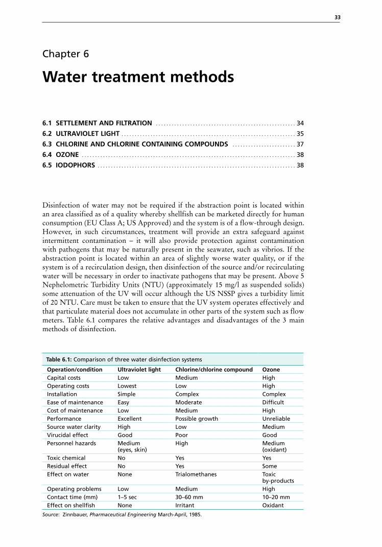
Disinfection of water may not be required if the abstraction point is located within an area classified as of a quality whereby shellfish can be marketed directly for human consumption (EU Class A; US Approved) and the system is of a flow-through design. However, in such circumstances, treatment will provide an extra safeguard against intermittent contamination – it will also provide protection against contamination with pathogens that may be naturally present in the seawater, such as vibrios. If the abstraction point is located within an area of slightly worse water quality, or if the system is of a recirculation design, then disinfection of the source and/or recirculating water will be necessary in order to inactivate pathogens that may be present. Above 5 Nephelometric Turbidity Units (NTU) (approximately 15 mg/l as suspended solids) some attenuation of the UV will occur although the US NSSP gives a turbidity limit of 20 NTU. Care must be taken to ensure that the UV system operates effectively and that particulate material does not accumulate in other parts of the system such as flow meters. Table 6.1 compares the relative advantages and disadvantages of the 3 main methods of disinfection.
Table 6.1: Comparison of three water disinfection systems
Operation/condition Ultraviolet light Chlorine/chlorine compound OzoneCapital costs Low Medium HighOperating costs Lowest Low HighInstallation Simple Complex ComplexEase of maintenance Easy Moderate DifficultCost of maintenance Low Medium HighPerformance Excellent Possible growth UnreliableSource water clarity High Low MediumVirucidal effect Good Poor GoodPersonnel hazards Medium
(eyes, skin) High
Medium(oxidant)
Toxic chemical No Yes YesResidual effect No Yes SomeEffect on water None Trialomethanes Toxic
by-productsOperating problems Low Medium HighContact time (mm) 1–5 sec 30–60 mm 10–20 mmEffect on shellfish None Irritant Oxidant
source: Zinnbauer, Pharmaceutical Engineering March-April, 1985.
Bivalve depuration: fundamental and practical aspects34
Additional treatment may also be applied to seawater that is recirculated (and especially re-used) in order to reduce concentrations of metabolic by-products from the shellfish (such as proteins and ammonia). These include protein skimmers and biofilters. Where used, these should be operated and maintained strictly according to manufacturer’s instructions or technical recommendations. As with all treatment systems, they need to be of sufficient capacity for the volume and flow of water to be treated. Biofilters should be placed prior to disinfection processes. This will ensure that residual chemical disinfectants do not inactivate the micro-organisms on the biofilters and that any micro-organisms released from the filter(s) (which could potentially include pathogens, e.g. vibrios) will be inactivated before reaching the shellfish. Location of skimmers prior to disinfection will also reduce the interference of the by-products with disinfection processes.
It is therefore necessary to place multiple components of water treatment systems in a logical order in order to maximise the performance of each, and the whole system. The target performance of each component should be known (e.g. the target dose for disinfection processes) and each unit should be operated and maintained according to the manufacturer’s instructions.
6.1 settlement and filtration
These are the two traditional approaches to reduction in turbidity of source water for depuration.
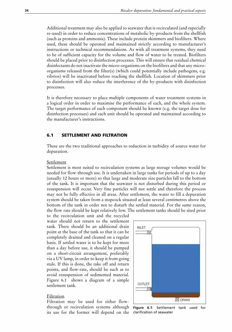
SettlementSettlement is most suited to recirculation systems as large storage volumes would be needed for flow-through use. It is undertaken in large tanks for periods of up to a day (usually 12 hours or more) so that large and moderate size particles fall to the bottom of the tank. It is important that the seawater is not disturbed during this period or resuspension will occur. Very fine particles will not settle and therefore the process may not be fully effective in all areas. After settlement, the water to fill a depuration system should be taken from a stopcock situated at least several centimetres above the bottom of the tank in order not to disturb the settled material. For the same reason, the flow rate should be kept relatively low. The settlement tanks should be sited prior to the recirculation unit and the recycled water should not return to the settlement tank. There should be an additional drain point at the base of the tank so that it can be completely drained and cleaned on a regular basis. If settled water is to be kept for more than a day before use, it should be pumped on a short-circuit arrangement, preferably via a UV lamp, in order to keep it from going stale. If this is done, the take off and return points, and flow-rate, should be such as to avoid resuspension of sedimented material. Figure 6.1 shows a diagram of a simple settlement tank.
FiltrationFiltration may be used for either flow-through or recirculation systems although its use for the former will depend on the
Figure 6.1: Settlement tank used for clarification of seawater
Chapter 6 – Water treatment methods 35
maximum flow capacity of the filter unit. Filters are used prior to the disinfection process. For recirculation units, the filter should be on the initial fill side of the plumbing system and not within the recirculation system itself as otherwise bacteria and other micro-organisms may grow on the filtration material and form a potential source of contamination within the system.
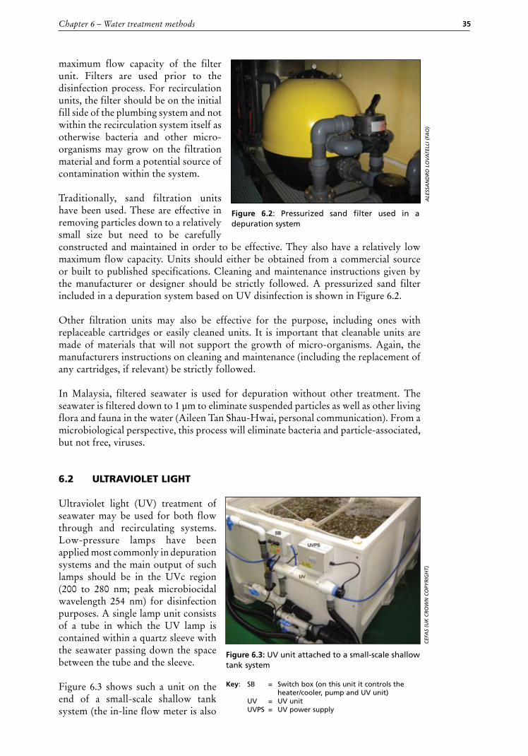
Traditionally, sand filtration units have been used. These are effective in removing particles down to a relatively small size but need to be carefully constructed and maintained in order to be effective. They also have a relatively low maximum flow capacity. Units should either be obtained from a commercial source or built to published specifications. Cleaning and maintenance instructions given by the manufacturer or designer should be strictly followed. A pressurized sand filter included in a depuration system based on UV disinfection is shown in Figure 6.2.
Other filtration units may also be effective for the purpose, including ones with replaceable cartridges or easily cleaned units. It is important that cleanable units are made of materials that will not support the growth of micro-organisms. Again, the manufacturers instructions on cleaning and maintenance (including the replacement of any cartridges, if relevant) be strictly followed.
In Malaysia, filtered seawater is used for depuration without other treatment. The seawater is filtered down to 1 µm to eliminate suspended particles as well as other living flora and fauna in the water (Aileen Tan Shau-Hwai, personal communication). From a microbiological perspective, this process will eliminate bacteria and particle-associated, but not free, viruses.
6.2 ultraviolet light
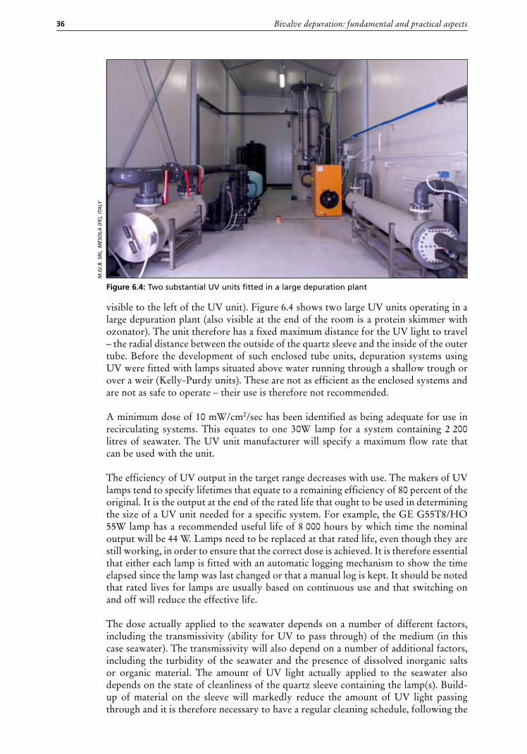
Ultraviolet light (UV) treatment of seawater may be used for both flow through and recirculating systems. Low-pressure lamps have been applied most commonly in depuration systems and the main output of such lamps should be in the UVc region (200 to 280 nm; peak microbiocidal wavelength 254 nm) for disinfection purposes. A single lamp unit consists of a tube in which the UV lamp is contained within a quartz sleeve with the seawater passing down the space between the tube and the sleeve.
Figure 6.3 shows such a unit on the end of a small-scale shallow tank system (the in-line flow meter is also
Figure 6.2: Pressurized sand filter used in a depuration system
AlE
ssA
nd
RO
lO
vA
TEll
I (FA
O)
Figure 6.3: UV unit attached to a small-scale shallow tank system
CEF
As
(uK
CR
Ow
n C
OPy
RIg
hT)
key: SB = Switch box (on this unit it controls the heater/cooler, pump and UV unit)
UV = UV unit UVPS = UV power supply
Bivalve depuration: fundamental and practical aspects36
visible to the left of the UV unit). Figure 6.4 shows two large UV units operating in a large depuration plant (also visible at the end of the room is a protein skimmer with ozonator). The unit therefore has a fixed maximum distance for the UV light to travel – the radial distance between the outside of the quartz sleeve and the inside of the outer tube. Before the development of such enclosed tube units, depuration systems using UV were fitted with lamps situated above water running through a shallow trough or over a weir (Kelly-Purdy units). These are not as efficient as the enclosed systems and are not as safe to operate – their use is therefore not recommended.
A minimum dose of 10 mW/cm2/sec has been identified as being adequate for use in recirculating systems. This equates to one 30W lamp for a system containing 2 200 litres of seawater. The UV unit manufacturer will specify a maximum flow rate that can be used with the unit.
The efficiency of UV output in the target range decreases with use. The makers of UV lamps tend to specify lifetimes that equate to a remaining efficiency of 80 percent of the original. It is the output at the end of the rated life that ought to be used in determining the size of a UV unit needed for a specific system. For example, the GE G55T8/HO 55W lamp has a recommended useful life of 8 000 hours by which time the nominal output will be 44 W. Lamps need to be replaced at that rated life, even though they are still working, in order to ensure that the correct dose is achieved. It is therefore essential that either each lamp is fitted with an automatic logging mechanism to show the time elapsed since the lamp was last changed or that a manual log is kept. It should be noted that rated lives for lamps are usually based on continuous use and that switching on and off will reduce the effective life.
The dose actually applied to the seawater depends on a number of different factors, including the transmissivity (ability for UV to pass through) of the medium (in this case seawater). The transmissivity will also depend on a number of additional factors, including the turbidity of the seawater and the presence of dissolved inorganic salts or organic material. The amount of UV light actually applied to the seawater also depends on the state of cleanliness of the quartz sleeve containing the lamp(s). Build-up of material on the sleeve will markedly reduce the amount of UV light passing through and it is therefore necessary to have a regular cleaning schedule, following the
Figure 6.4: Two substantial UV units fitted in a large depuration plant
M.g
I.B. s
Rl,
MEs
OlA
(FE
), IT
Aly
Chapter 6 – Water treatment methods 37
manufacturer’s instructions for cleaning. It should be noted that any materials used in the cleaning process should be approved for use in food production premises and the units should anyway be thoroughly rinsed following the cleaning process.
UV dosage can be quoted as either the applied dose (usually calculated from the output of the lamp - either theoretical or measured) and the transmissivity of the seawater, or as the received dose (actually measured at the wall of the tube containing the lamp). In practice, devices for measuring UV dose vary greatly in their performance and the most practical way to determine the required dose is to base this on the theoretical performance of the lamp and to control the transmissivity of the water as far as possible (e.g. by including settlement/filtration), as necessary.
UV radiation can be harmful to both the eyes and the skin. The use of lamps in sealed opaque units means that staff are not exposed to the radiation. Some units have translucent end-caps that will transmit visible light emitted by the lamp so that it is obvious whether they are working. Otherwise, other evidence that the lamp is on needs to be provided so that it is possible to check functioning at the start of depuration and at regular periods during the cycle. It must be noted that evidence that the lamp is functioning does NOT mean that the output is satisfactory. Monitoring of use and subsequent replacement after the prescribed number of hours is necessary whether the lamp is on or not.
When dismantling and reassembling units during cleaning or lamp replacement, the manufacturer’s instructions should be followed closely so that lamps are not damaged and so that water is kept away from the electrical fittings.
6.3 chlorine and chlorine containing compounds
Chlorine was one of the earliest means used to disinfect seawater for depuration. When used with seawater of low to moderate sediment and organic loads, it is an effective bactericide. However, there are concerns with its effectiveness against viruses.
Addition of chlorine is usually undertaken by the use of sodium hypochlorite solution, although chlorine-generating compounds and chlorine gas may be used (NB. The latter is hazardous). In Japan, some plants use in-line electrolysis of seawater to generate chlorine.
For the purposes of depuration, 2 to 3 mg/l free chlorine is normally used for a contact time of up to an hour. In Morocco, the competent authority specifies a maximum free chlorine concentration of 3 mg/l and a contact time of at least one hour.
The amount of chlorine solution required may be determined using the following formula:
Volume to add (litres) = Final concentration required (mg/l) x tank volume (litres) Concentration of stock solution (mg/l)
e.g. to get a 3 mg/l final concentration with a tank volume of 1 000 litres and a stock solution concentration of 10 percent (100 000 mg/l) free chlorine:
Volume to add (litres) = 3 x 1 000 100 000
= 0.03 litres = 30 ml
Bivalve depuration: fundamental and practical aspects38
Before use it is necessary to reduce free chlorine in the water to less than 0.1 mg/l otherwise the shellfish will not show the required activity and depuration will be impaired. This reduction is achieved by the addition of sodium thiosulphate. There are also concerns that by-products formed in contact with organic materials in seawater may be accumulated by the shellfish and may pose potential long-term health risks in humans.
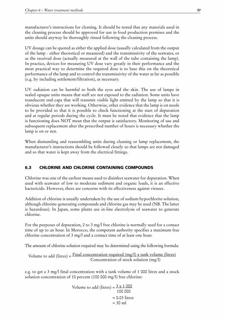
For chlorination of intake water in Japan using an electrolyzer (see Figure 6.5), containing 3.0 to 3.3 percent (30 to 33 ppt) of NaCl is decomposed by passing over the electrode. Usually, 0.2 to 0.3 mg/l chlorine is used for disinfection. This concentration does not show the toxicity for the oysters and but has been shown to inactivate E. coli, V. parahaemolyticus and Feline Calicivirus (FCV), a norovirus surrogate.
6.4 ozone
Ozone is very effective at inactivating both bacteria and viruses. It may be purchased as the gas form in cylinders or produced on-site by means of high energy electrical discharge or UV light (peak wavelength at 185 nm rather than the 254 nm used for UV disinfection). The ozone is then introduced into the seawater via a diffuser in order to get good mixing.
Ozone is a relatively expensive form of disinfection and the gas is very toxic. Therefore, strict safety rules need to be observed. Ozone at a concentration not exceeding 0.5 mg/l (in order to minimize bromate production – see below) can be used to treat seawater in batches for periods up to 10 minutes. This is undertaken in a separate tank to that used for depuration and then the residual ozone has to be discharged from the seawater before use so that it does not adversely affect the animals – this is achieved by aeration.
There are two additional concerns with the use of ozone – the first is that bromates are formed when ozone is in contact with seawater and these are regarded as potential cancer forming compounds. The second is that residual levels of ozone may cause the shellfish to reduce or stop activity, thus reducing the effectiveness of the depuration process.
6.5 iodophors
Systems using iodophors have been used in the past in Italy and attempts have been made to market them in other countries. The intention is that, as well as disinfecting the depuration water, low residual levels of the iodophors within the intestinal tract of the shellfish will have a direct microbiocidal effect, including against viruses. However, concerns have been expressed with regard to the extent of activity against viruses. Systems in Italy now predominantly use UV or ozone.
Figure 6.5: Electrolyzer with flow meter used for oyster depuration
MA
MO
Ru
yO
shIM
Izu
39
Chapter 7
Pre-depuration considerations
7.1 HARvEST . . . . . . . . . . . . . . . . . . . . . . . . . . . . . . . . . . . . . . . . . . . . . . . . . . . . . . . . . . . . . . . . . . . . . . . . . . . . . . 39
7.2 TRANSPORT . . . . . . . . . . . . . . . . . . . . . . . . . . . . . . . . . . . . . . . . . . . . . . . . . . . . . . . . . . . . . . . . . . . . . . . . . . . 39
7.3 GENERAL HANDLING . . . . . . . . . . . . . . . . . . . . . . . . . . . . . . . . . . . . . . . . . . . . . . . . . . . . . . . . . . . . . . . . 39
7.4 STORAGE . . . . . . . . . . . . . . . . . . . . . . . . . . . . . . . . . . . . . . . . . . . . . . . . . . . . . . . . . . . . . . . . . . . . . . . . . . . . . . 40
7.5 WASHING, CULLING AND DEBySSINGS . . . . . . . . . . . . . . . . . . . . . . . . . . . . . . . . . . . . . . . . . . . 40
7.1 harvest
Harvesting techniques should not result in marked shock to the animals, or visible damage to the shells as these may result in either a lower depuration efficiency or increased mortality, either in the depuration system or post-depuration. In general, hand-picking and raking techniques cause least shock and damage to the animals while mechanical harvesting techniques have the potential to cause the most. However, the significance depends on both the animal species and the particular method. For example, cockles (Cerastoderma edule) show a relatively high rate of damage when harvested mechanically.
7.2 transport
Transport procedures should protect the shellfish from contamination, extremes of temperature and physical damage or excessive vibration. Protection from contamination means that the shellfish should be raised off the floor of any vehicle, to keep them out of any draining water, and that they be covered. See Section 7.4 regarding ideal storage temperatures.
Some species are unable to form a water-tight seal when they close and this may give additional constraints on transport times. In the UK, a maximum of 6 hours between harvesting and the start of depuration is specified for both cockles (C. edule) and razor clams (Ensis spp.). In addition, for razor clams, it is required that they be placed in bundles of a maximum of 12 animals, normally secured by an elastic band, in order that they retain integrity and viability.
7.3 general handling
Handling procedures at all stages should avoid shock to the animals. In particular, bulk handling should be undertaken in such a way as to avoid dropping the animals onto hard surfaces and to avoid crushing or other damage. Although the majority of animals may survive such procedures their ability to depurate and shelf-life will be impaired.
Bivalve depuration: fundamental and practical aspects40
7.4 storage
Shellfish received at the plant should be stored in such a manner as to prevent contamination and to avoid exposure to extremes of temperature (either heat or cold), preferably within a reception area in the plant. They should be raised off the ground and, if not stored inside, they should be covered. Extremes of temperature can reduce or subsequent depuration effectiveness and high temperatures can lead to multiplication of bacteria, particularly vibrios. The target storage range is normally considered to be 2 to 10 °C, although the characteristics of the local species need to be considered when determining the actual range specified. Local regulations may stipulate other ranges for storage and transport.
7.5 Washing, culling and deByssing
Any mud or other material must be removed from the outside of the shellfish prior to them being placed into containers (trays/baskets) for loading into the depuration tank(s). The shellfish must also be sorted and inspected and any dead or damaged shellfish, other species, seaweed, etc., must be removed. These operations are necessary to minimize the amount of external contaminants entering the tank(s) and to avoid the possibility of dead shellfish and other species decaying in the tanks. The presence of predators (such as starfish) left in amongst the shellfish may cause stress and prevent them from depurating properly. Mechanical devices are available commercially for the removal of broken shellfish and other debris, including a rinsing facility, but this still needs to be supplemented by visual inspection.
The byssal threads on mussel must be removed before they are placed in containers for depuration. There are a number of commercially available devices for performing this operation.