Embed Size (px)
Citation preview
November 2008 PKGP-PRC003-EN
Precedent™- R-223-10 Tons – 60 Hz
Packaged Heat Pumps (WSC)
Packaged Heat Pumps
© 2008 Trane All rights reserved PKGP-PRC003-EN
Introduction
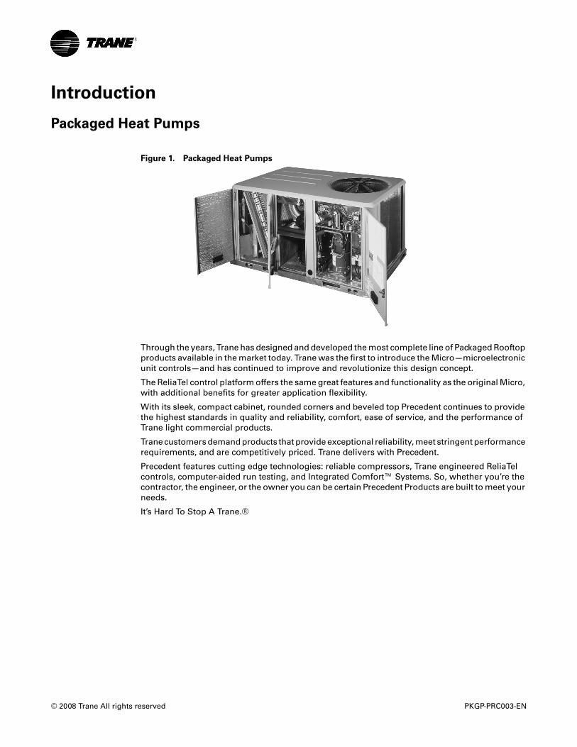
Packaged Heat Pumps
Through the years, Trane has designed and developed the most complete line of Packaged Rooftop products available in the market today. Trane was the first to introduce the Micro—microelectronic unit controls—and has continued to improve and revolutionize this design concept.
The ReliaTel control platform offers the same great features and functionality as the original Micro, with additional benefits for greater application flexibility.
With its sleek, compact cabinet, rounded corners and beveled top Precedent continues to provide the highest standards in quality and reliability, comfort, ease of service, and the performance of Trane light commercial products.
Trane customers demand products that provide exceptional reliability, meet stringent performance requirements, and are competitively priced. Trane delivers with Precedent.
Precedent features cutting edge technologies: reliable compressors, Trane engineered ReliaTel controls, computer-aided run testing, and Integrated Comfort™ Systems. So, whether you’re the contractor, the engineer, or the owner you can be certain Precedent Products are built to meet your needs.
It’s Hard To Stop A Trane.®
Figure 1. Packaged Heat Pumps
Table of Contents
PKGP-PRC003-EN 3
Introduction . . . . . . . . . . . . . . . . . . . . . . . . . . . . . . . . . . . . . . . . . . . . . . . . . . . . . . . . . . . . 2
Packaged Heat Pumps . . . . . . . . . . . . . . . . . . . . . . . . . . . . . . . . . . . . . . . . . . . . . . 2
Features and Benefits . . . . . . . . . . . . . . . . . . . . . . . . . . . . . . . . . . . . . . . . . . . . . . . . . . . 5
Standard Features . . . . . . . . . . . . . . . . . . . . . . . . . . . . . . . . . . . . . . . . . . . . . . . . . 5
Options* . . . . . . . . . . . . . . . . . . . . . . . . . . . . . . . . . . . . . . . . . . . . . . . . . . . . . . . . . . 5
Other Benefits . . . . . . . . . . . . . . . . . . . . . . . . . . . . . . . . . . . . . . . . . . . . . . . . . . . . . 6
Standard Features . . . . . . . . . . . . . . . . . . . . . . . . . . . . . . . . . . . . . . . . . . . . . . . . . 7
Variety of Options* . . . . . . . . . . . . . . . . . . . . . . . . . . . . . . . . . . . . . . . . . . . . . . . . . 9Factory Installed Options* . . . . . . . . . . . . . . . . . . . . . . . . . . . . . . . . . . . . . . 9Factory or Field Installed Options* . . . . . . . . . . . . . . . . . . . . . . . . . . . . . . 11Field Installed Options* . . . . . . . . . . . . . . . . . . . . . . . . . . . . . . . . . . . . . . . 12
Other Benefits . . . . . . . . . . . . . . . . . . . . . . . . . . . . . . . . . . . . . . . . . . . . . . . . . . . . 13Rigorous Testing . . . . . . . . . . . . . . . . . . . . . . . . . . . . . . . . . . . . . . . . . . . . . 15
Application Considerations . . . . . . . . . . . . . . . . . . . . . . . . . . . . . . . . . . . . . . . . . . . . . 16
Selection Procedure . . . . . . . . . . . . . . . . . . . . . . . . . . . . . . . . . . . . . . . . . . . . . . . . . . . 17Cooling Capacity . . . . . . . . . . . . . . . . . . . . . . . . . . . . . . . . . . . . . . . . . . . . . 17Heating Capacity . . . . . . . . . . . . . . . . . . . . . . . . . . . . . . . . . . . . . . . . . . . . . 18Air Delivery Selection . . . . . . . . . . . . . . . . . . . . . . . . . . . . . . . . . . . . . . . . . 18Model Number Notes . . . . . . . . . . . . . . . . . . . . . . . . . . . . . . . . . . . . . . . . . 19
Model Number Description - 3-10 Ton R-22 . . . . . . . . . . . . . . . . . . . . . . . . . . . . . . 19
General Data . . . . . . . . . . . . . . . . . . . . . . . . . . . . . . . . . . . . . . . . . . . . . . . . . . . . . . . . . . 21
Performance Data . . . . . . . . . . . . . . . . . . . . . . . . . . . . . . . . . . . . . . . . . . . . . . . . . . . . . 27
Direct Drive - Evaporator Fan Performance . . . . . . . . . . . . . . . . . . . . . . . . . . . . . . . 33
Evaporator Fan Performance . . . . . . . . . . . . . . . . . . . . . . . . . . . . . . . . . . . . . . . . . . . 34
Fan Performance . . . . . . . . . . . . . . . . . . . . . . . . . . . . . . . . . . . . . . . . . . . . . . . . . . . . . . 46
Heating Performance Data . . . . . . . . . . . . . . . . . . . . . . . . . . . . . . . . . . . . . . . . . . . . . . 50
Controls . . . . . . . . . . . . . . . . . . . . . . . . . . . . . . . . . . . . . . . . . . . . . . . . . . . . . . . . . . . . . . 59ReliaTel™ Controlled Units . . . . . . . . . . . . . . . . . . . . . . . . . . . . . . . . . . . . 59
Electrical Data . . . . . . . . . . . . . . . . . . . . . . . . . . . . . . . . . . . . . . . . . . . . . . . . . . . . . . . . . 62
Jobsite Connections . . . . . . . . . . . . . . . . . . . . . . . . . . . . . . . . . . . . . . . . . . . . . . . . . . . 68
Dimensional Data . . . . . . . . . . . . . . . . . . . . . . . . . . . . . . . . . . . . . . . . . . . . . . . . . . . . . . 69
Weights . . . . . . . . . . . . . . . . . . . . . . . . . . . . . . . . . . . . . . . . . . . . . . . . . . . . . . . . . . . . . . 77
Mechanical Specifications . . . . . . . . . . . . . . . . . . . . . . . . . . . . . . . . . . . . . . . . . . . . . . 78Factory Installed Options . . . . . . . . . . . . . . . . . . . . . . . . . . . . . . . . . . . . . . 79
4 PKGP-PRC003-EN
Factory or Field Installed Options . . . . . . . . . . . . . . . . . . . . . . . . . . . . . . . 80Field Installed Options . . . . . . . . . . . . . . . . . . . . . . . . . . . . . . . . . . . . . . . . 81
PKGP-PRC003-EN 5
Features and Benefits
Standard Features
• 5-year Limited Compressor Warranty
• 5-year Limited Heat Exchanger Warranty
• 1-year Limited Parts Warranty
• Anti-Short Cycle Timer (Standard with ReliaTel™)
• Belt Drive Motors (6-10 Tons)
• Colored and Numbered Wiring
• Convertible Airflow
• Direct Drive Motors (3-5 Tons)
• Easy Access Low Voltage Terminal Board (LTB)
• Filters are Standard on all Units
• Foil-Faced and Edge Captured Insulation
• IAQ Dual Sloped and Removable Drain Pans
• Liquid Line Refrigerant Drier
• Low Ambient Cooling to 0°F
• Operating Charge of R-22
• Patent-Pending Hybrid Condenser Coil for easy cleaning
• Phase Reversal Protection1
• Provisions for Condensate Drain Connections
• Quick Access Panels
• Quick Adjust Fan Motor Mounting Plate
• Single Point Power
• Single Side Service
• Standardized Components
• Trane built Scroll Compressors
Options*
Note: *Refer to Model Number Description for option availability.
Factory Installed Options
• Belt Drive Motors (3-5 tons)
• Black Epoxy Pre-Coated Coils
• High Pressure Cutout
• Hinged Access Doors
• Powered or Unpowered Convenience Outlet
• Supply and/or Return Air Smoke Detector
• Through the Base Electrical Access
• Through the Base Electrical with Circuit Breaker
1 Only available for 3-5 Ton Direct Drive
6 PKGP-PRC003-EN
Features and Benefits
• Through the Base Electrical with Disconnect Switch
• 2” Pleated Filters
Factory or Field Installed Options
• Barometric Relief
• Clogged Filter/Fan Failure Switch
• Crankcase Heaters
• Discharge Air Sensing Kit
• Economizer
• Electric Heaters
• Frostat
• LonTalk® Communications Interface (LCI)
• Oversized Motors
• Reference or Comparative Enthalpy
• Tool-less Hail Guards
• Trane Communications Interface (TCI)
Field Installed Options
• CO2 Sensing
• Dual Thermistor Remote Zone Sensor
• High Altitude Kit
• High Static Drive
• Manual Outside Air Damper
• Motorized Outside Air Dampers
• Powered Exhaust
• Quick Adapt Curbs
• Quick Start Kit
• Remote Potentiometer
• Roof Curb
• Thermostat
• Zone Sensor
Other Benefits
• Cabinet design ensures water integrity
• Ease of Service, Installation and Maintenance
• Mixed model build enables “fastest in the industry” ship cycle times
• Outstanding Airflow Distribution
• ReliaTel Controls
• Unmatched Product Support is one of our finest assets. Trane Sales Representatives are a Support Group that can assist you with:
• Product
• Application
• Service
PKGP-PRC003-EN 7
Features and Benefits
• Training
• Special Applications
• Specifications
• Computer Programs and much more
Standard Features
Anti-Short Cycle Timer (Standard with ReliaTel)
Provides a 3 minute minimum “ON” time and 3 minute “OFF” time for compressors to enhance compressor reliability by assuring proper oil return.
Colored And Numbered Wiring
Save time and money tracing wires and diagnosing the unit.
Controls – ReliaTel or Electromechanical
ReliaTel microprocessor controls provide unit control for heating, cooling and ventilating utilizing input from sensors that measure indoor and outdoor temperature and other zone sensors. ReliaTel also provides outputs for building automation systems and expanded diagnostics. For a complete list of ReliaTel offerings, refer to the “Other Benefits” section within the Features and Benefits section of this catalog.
For the simpler job that does not require a building automation system, or expanded diagnostics capabilities, Precedent offers electromechanical controls. This 24-volt control includes the control transformer and contactor pressure lugs for power wiring.
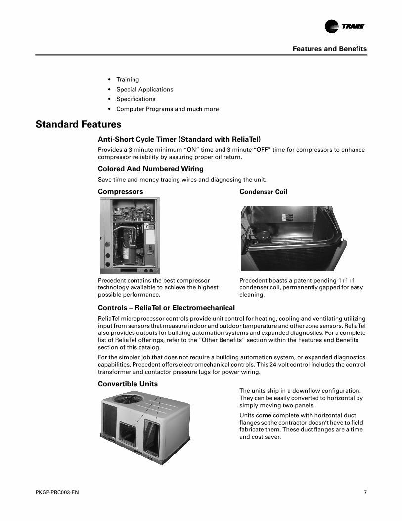
Compressors Condenser Coil
Precedent contains the best compressor technology available to achieve the highest possible performance.
Precedent boasts a patent-pending 1+1+1 condenser coil, permanently gapped for easy cleaning.
Convertible UnitsThe units ship in a downflow configuration. They can be easily converted to horizontal by simply moving two panels.
Units come complete with horizontal duct flanges so the contractor doesn’t have to field fabricate them. These duct flanges are a time and cost saver.
8 PKGP-PRC003-EN
Features and Benefits
Cooling
Standard or High Efficiency Cooling available.
Low Ambient Cooling
All Precedent microprocessor units have cooling capabilities down to 0°F as standard.
Motors
Belt or direct drive - standard or oversized supply fan motors meet a wide airflow range.
Phase Reversal Protection1
100% protection shall be standard for motors and compressors against problems caused by phase loss, phase imbalance and phase reversal indication.
Quick-Access Panels
Remove two screws for access to the standardized internal components and wiring.
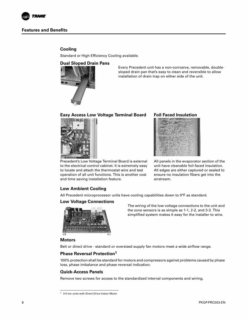
Dual Sloped Drain PansEvery Precedent unit has a non-corrosive, removable, double-sloped drain pan that’s easy to clean and reversible to allow installation of drain trap on either side of the unit.
Easy Access Low Voltage Terminal Board Foil Faced Insulation
Precedent’s Low Voltage Terminal Board is external to the electrical control cabinet. It is extremely easy to locate and attach the thermostat wire and test operation of all unit functions. This is another cost and time saving installation feature.
All panels in the evaporator section of the unit have cleanable foil-faced insulation. All edges are either captured or sealed to ensure no insulation fibers get into the airstream.
Low Voltage ConnectionsThe wiring of the low voltage connections to the unit and the zone sensors is as simple as 1-1, 2-2, and 3-3. This simplified system makes it easy for the installer to wire.
1 3-5 ton units with Direct Drive Indoor Motor
PKGP-PRC003-EN 9
Features and Benefits
Quick-Adjust Idler Arm
With the Quick-Adjust Idler Arm, the belt and sheaves can be quickly adjusted without moving the mounted fan motor. The result is a major savings in time and money.
Single Point Power
A single electrical connection powers the unit.
Single Side Service
Single side service is standard on all units.
Standardized Components
Components are placed in the same location on all Precedent units. Familiarize yourself with one Precedent and you are familiar with every Precedent.
Due to standardized components throughout the Precedent line, contractors/owners can stock fewer parts.
Through the Base Condensate
Every unit includes provisions for through the base condensate drain connections. This allows the drain to be connected through the roof curb instead of a roof penetration.
Variety of Options*
Factory Installed Options*
Note: *Refer to Model Number Description for option availability.
Black Epoxy Pre-Coated Coils
The pre-coated coils are an economical option for protection in mildly corrosive environments.
Disconnect Switch (Required with Through-the-Base Electrical)
Factory installed 3-pole, molded case, disconnect switch with provisions for through the base electrical connections are available.
Codes require a method of assured unit shutdown for servicing. Field-installed disconnects sometimes interfere with service access. Factory installation of unit disconnects reduces costs, assures proper mounting and provides the opportunity to upgrade to unit circuit breaker protection.
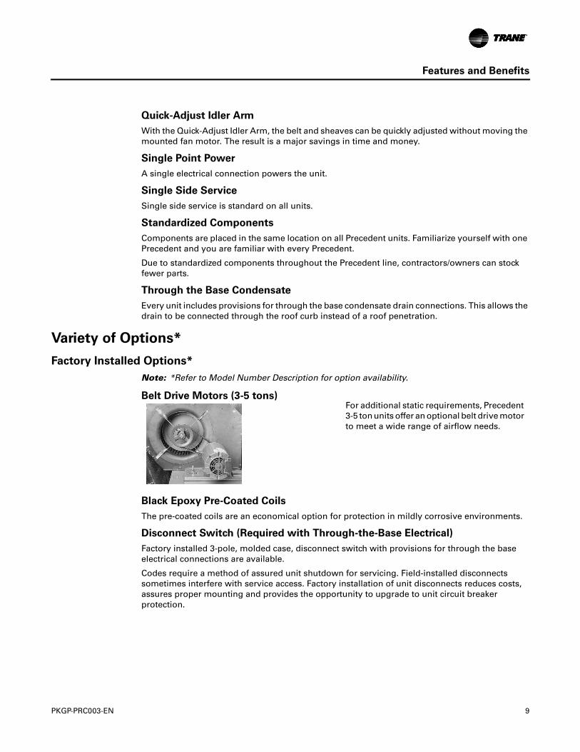
Belt Drive Motors (3-5 tons)For additional static requirements, Precedent 3-5 ton units offer an optional belt drive motor to meet a wide range of airflow needs.
10 PKGP-PRC003-EN
Features and Benefits
High Pressure Cutout
This factory-installed option is offered for units that do not have High Pressure Cutout as standard. All 3-phase units with scroll compressors include High Pressure Cutout as standard.
Phase Monitor
Phase monitor shall provide 100% protection for motors and compressors against problems caused by phase loss, phase imbalance, and phase reversal. Phase monitor is equipped with an LED that provides an ON or FAULT indicator.
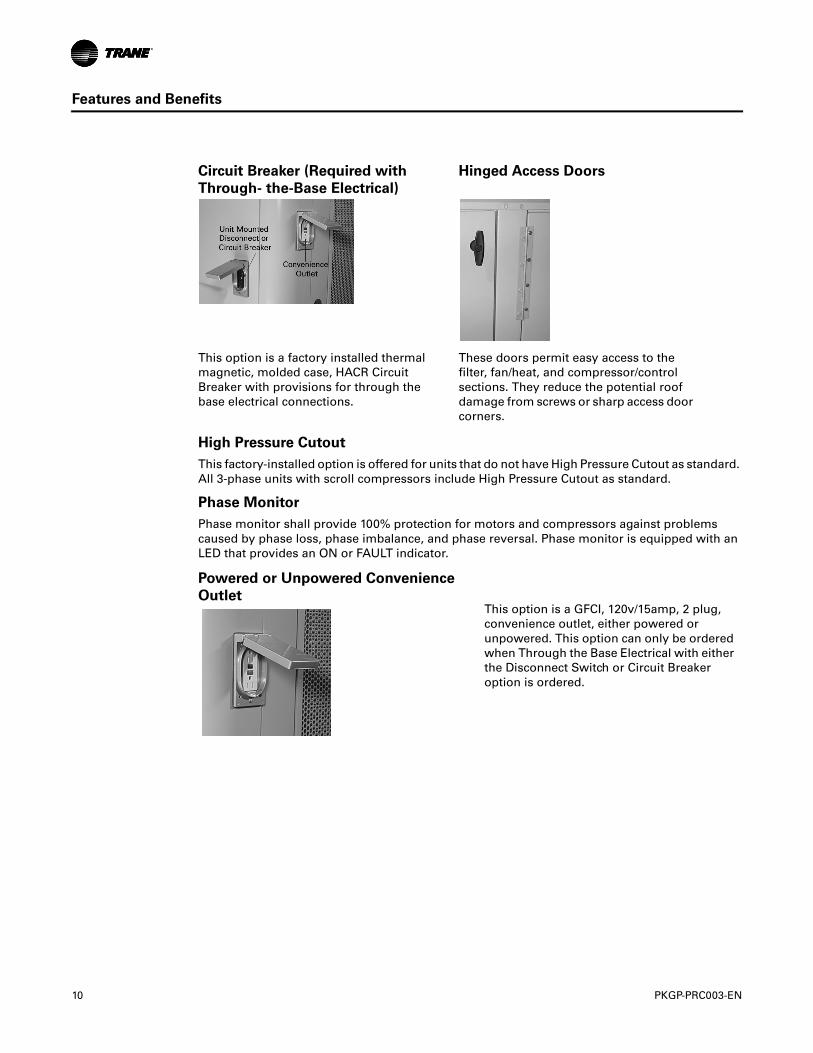
Circuit Breaker (Required with
Through- the-Base Electrical)
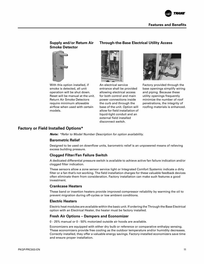
Hinged Access Doors
This option is a factory installed thermal magnetic, molded case, HACR Circuit Breaker with provisions for through the base electrical connections.
These doors permit easy access to the filter, fan/heat, and compressor/control sections. They reduce the potential roof damage from screws or sharp access door corners.
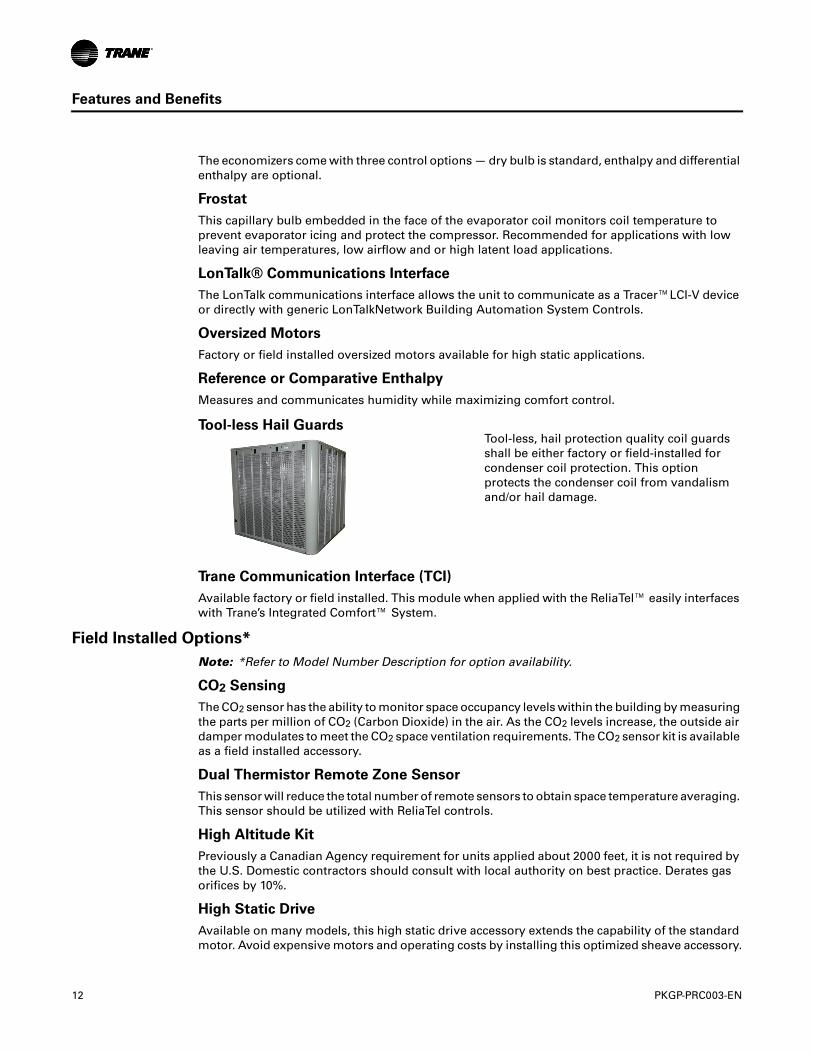
Powered or Unpowered Convenience
OutletThis option is a GFCI, 120v/15amp, 2 plug, convenience outlet, either powered or unpowered. This option can only be ordered when Through the Base Electrical with either the Disconnect Switch or Circuit Breaker option is ordered.
PKGP-PRC003-EN 11
Features and Benefits
Factory or Field Installed Options*
Note: *Refer to Model Number Description for option availability.
Barometric Relief
Designed to be used on downflow units, barometric relief is an unpowered means of relieving excess building pressure.
Clogged Filter/Fan Failure Switch
A dedicated differential pressure switch is available to achieve active fan failure indication and/or clogged filter indication.
These sensors allow a zone sensor service light or Integrated Comfort Systemic indicate a dirty filter or a fan that’s not working. The field installation charges for these valuable feedback devices often eliminate them from consideration. Factory installation can make such features a good investment.
Crankcase Heaters
These band or insertion heaters provide improved compressor reliability by warming the oil to prevent migration during off-cycles or low ambient conditions.
Electric Heaters
Electric heat modules are available within the basic unit. If ordering the Through the Base Electrical option with an Electrical Heater, the heater must be factory installed.
Fresh Air Options – Dampers and Economizer
0 - 25% manual or 0 - 50% motorized outside air hoods are available.
Economizers are equipped with either dry bulb or reference or comparative enthalpy sensing. These economizers provide free cooling as the outdoor temperature and/or humidity decreases. Correctly installed, they offer a valuable energy savings. Factory-installed economizers save time and ensure proper installation.
Supply and/or Return Air
Smoke Detector
Through-the-Base Electrical Utility Access
With this option installed, if smoke is detected, all unit operation will be shut down. Reset will be manual at the unit. Return Air Smoke Detectors require minimum allowable airflow when used with certain models.
An electrical service entrance shall be provided allowing electrical access for both control and main power connections inside the curb and through the base of the unit. Option will allow for field installation of liquid-tight conduit and an external field installed disconnect switch.
Factory provided through the base openings simplify wiring and piping. Because these utility openings frequently minimize the number of roof penetrations, the integrity of roofing materials is enhanced.
12 PKGP-PRC003-EN
Features and Benefits
The economizers come with three control options — dry bulb is standard, enthalpy and differential enthalpy are optional.
Frostat
This capillary bulb embedded in the face of the evaporator coil monitors coil temperature to prevent evaporator icing and protect the compressor. Recommended for applications with low leaving air temperatures, low airflow and or high latent load applications.
LonTalk® Communications Interface
The LonTalk communications interface allows the unit to communicate as a Tracer™LCI-V device or directly with generic LonTalkNetwork Building Automation System Controls.
Oversized Motors
Factory or field installed oversized motors available for high static applications.
Reference or Comparative Enthalpy
Measures and communicates humidity while maximizing comfort control.
Trane Communication Interface (TCI)
Available factory or field installed. This module when applied with the ReliaTel™ easily interfaces with Trane’s Integrated Comfort™ System.
Field Installed Options*
Note: *Refer to Model Number Description for option availability.
CO2 Sensing
The CO2 sensor has the ability to monitor space occupancy levels within the building by measuring the parts per million of CO2 (Carbon Dioxide) in the air. As the CO2 levels increase, the outside air damper modulates to meet the CO2 space ventilation requirements. The CO2 sensor kit is available as a field installed accessory.
Dual Thermistor Remote Zone Sensor
This sensor will reduce the total number of remote sensors to obtain space temperature averaging. This sensor should be utilized with ReliaTel controls.
High Altitude Kit
Previously a Canadian Agency requirement for units applied about 2000 feet, it is not required by the U.S. Domestic contractors should consult with local authority on best practice. Derates gas orifices by 10%.
High Static Drive
Available on many models, this high static drive accessory extends the capability of the standard motor. Avoid expensive motors and operating costs by installing this optimized sheave accessory.
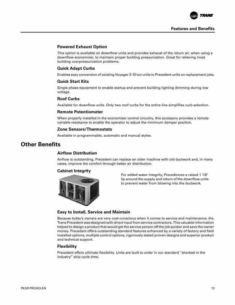
Tool-less Hail GuardsTool-less, hail protection quality coil guards shall be either factory or field-installed for condenser coil protection. This option protects the condenser coil from vandalism and/or hail damage.
PKGP-PRC003-EN 13
Features and Benefits
Powered Exhaust Option
This option is available on downflow units and provides exhaust of the return air, when using a downflow economizer, to maintain proper building pressurization. Great for relieving most building overpressurization problems.
Quick Adapt Curbs
Enables easy conversion of existing Voyager 3-10 ton units to Precedent units on replacement jobs.
Quick Start Kits
Single phase equipment to enable startup and prevent building lighting dimming during low voltage.
Roof Curbs
Available for downflow units. Only two roof curbs for the entire line simplifies curb selection.
Remote Potentiometer
When properly installed in the economizer control circuitry, this accessory provides a remote variable resistance to enable the operator to adjust the minimum damper position.
Zone Sensors/Thermostats
Available in programmable, automatic and manual styles.
Other Benefits
Airflow Distribution
Airflow is outstanding. Precedent can replace an older machine with old ductwork and, in many cases, improve the comfort through better air distribution.
Easy to Install, Service and Maintain
Because today’s owners are very cost-conscious when it comes to service and maintenance, the Trane Precedent was designed with direct input from service contractors. This valuable information helped to design a product that would get the service person off the job quicker and save the owner money. Precedent offers outstanding standard features enhanced by a variety of factory and field installed options, multiple control options, rigorously tested proven designs and superior product and technical support.
Flexibility
Precedent offers ultimate flexibility. Units are built to order in our standard “shortest in the industry” ship cycle time.
Cabinet IntegrityFor added water integrity, Precedences a raised 1 1/8" lip around the supply and return of the downflow units to prevent water from blowing into the ductwork.
14 PKGP-PRC003-EN
Features and Benefits
ReliaTel eliminates the need for field installed anti-shortcycle timer and time delay relays. ReliaTel controls provide these functions as an integral part of the unit. The contractor no longer has to purchase these controls as options and pay to install them.
The wiring of the low voltage connections to the unit and the zone sensors is as easy as 1-1, 2-2, and 3-3. This simplified system makes wiring easier for the installer.
ReliaTel Makes Testing Easy
ReliaTel requires no special tools to run the Precedent unit through its paces. Simply place a jumper between Test 1 and Test 2 terminals on the Low Voltage Terminal Board and the unit will walk through its operational steps automatically.
The unit automatically returns control to the zone sensor after stepping through the test mode a single time, even if the jumper is left on the unit.
As long as the unit has power and the “system on” LED is lit, ReliaTel is operational. The light indicates that the controls are functioning properly.
ReliaTel features expanded diagnostic capabilities when utilized with Trane Integrated Comfort™ Systems.
Some zone sensor options have central control panel lights which indicate the mode the unit is in and possible diagnostic information (dirty filters for example).
Other ReliaTel Benefits
The ReliaTel built-in anti-shortcycle timer, time delay relay and minimum “on” time control functions are factory tested to assure proper operation.
ReliaTel softens electrical “spikes” by staging on fans, compressors and heaters.
Intelligent Fallback is a benefit to the building occupant. If a component fails, the unit will continue to operate at predetermined temperature setpoint.
Intelligent Anticipation is a standard ReliaTel feature. It functions continuously as ReliaTel and zone sensor(s) work together in harmony to provide much tighter comfort control than conventional electro-mechanical thermostats.
The same ReliaTel Board fits all Packaged Gas/Electric, Cooling with Electric Heat, and Heat Pump models. This provides standardization of parts for contractors. Less money is tied up in inventory with ReliaTel.
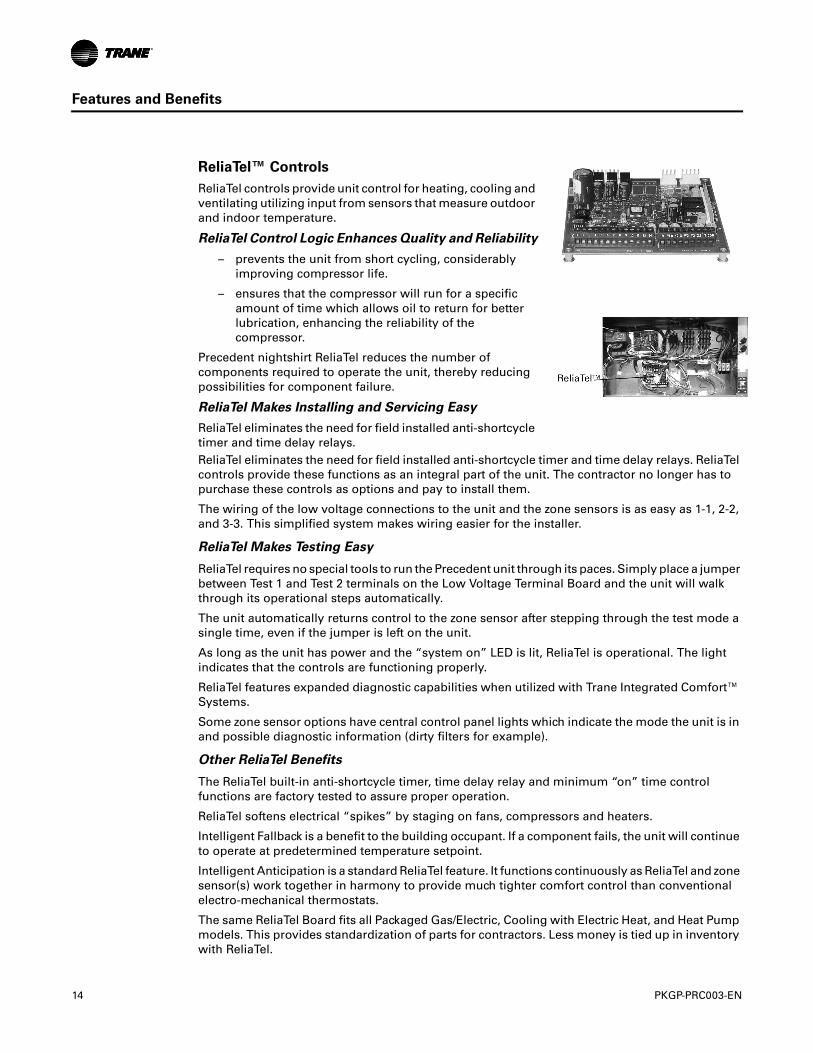
ReliaTel™ Controls
ReliaTel controls provide unit control for heating, cooling and ventilating utilizing input from sensors that measure outdoor and indoor temperature.
ReliaTel Control Logic Enhances Quality and Reliability
– prevents the unit from short cycling, considerably improving compressor life.
– ensures that the compressor will run for a specific amount of time which allows oil to return for better lubrication, enhancing the reliability of the compressor.
Precedent nightshirt ReliaTel reduces the number of components required to operate the unit, thereby reducing possibilities for component failure.
ReliaTel Makes Installing and Servicing Easy
ReliaTel eliminates the need for field installed anti-shortcycle timer and time delay relays.
PKGP-PRC003-EN 15
Features and Benefits
Unit Cabinet
The compact cabinet with rounded corners takes up less room and is less costly to ship. The beveled and ribbed top is not only aesthetically pleasing, it is designed to prevent water from pooling.
Rigorous Testing
All of Precedent’s designs were rigorously rain tested at the factory to ensure water integrity.
Actual shipping tests were performed to determine packaging requirements. Units were test shipped around the country to determine the best packaging. Factory shake and drop tests were used as part of the package design process to help assure that the unit arrives at the job site in top condition.
Rigging tests include lifting a unit into the air and letting it drop one foot, assuring that the lifting lugs and rails hold up under stress.
We perform a 100% coil leak test at the factory. The evaporator and condenser coils are leak tested at 575 psig and pressure tested to 450 psig.
All parts are inspected at the point of final assembly. Sub-standard parts are identified and rejected immediately.
Every unit receives a 100% unit run test before leaving the production line to make sure it lives up to rigorous Trane requirements.
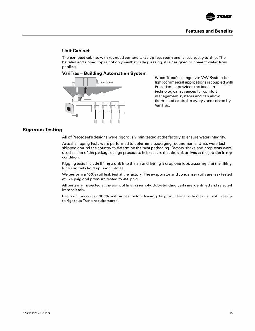
VariTrac – Building Automation SystemWhen Trane’s changeover VAV System for light commercial applications is coupled with Precedent, it provides the latest in technological advances for comfort management systems and can allow thermostat control in every zone served by VariTrac.
16 PKGP-PRC003-EN
Application Considerations
Application of this product should be within the cataloged airflow and cooling considerations.
Barometric Relief
This product line offers an optional barometric relief damper for use in conjunction with economizer option. This accessory consists of gravity dampers which open with increased pressure. As the building air pressure increases, the pressure in the unit return air section also increases, opening the dampers and relieving the conditioned space.
Note: The effectiveness of barometric relief damper during economizing operation is system related. Pressure drop of the return air system should be considered to control building pressurization.
Black Epoxy Coil
The coils are manufactured with a thermoset, vinyl coating that is bonded to the aluminum fin stock prior to the fin stamping process. These coils are an economical option for protection in mildly corrosive environments.
Note: Not to be used where seacoast applications exist.
Clearance Requirements
The recommended clearances identified with unit dimensions should be maintained to assure adequate service maximum capacity and peak operating efficiency. Actual clearances which appear inadequate should be reviewed with the local Trane sales personnel.
Condensate Trap
The evaporator is a draw-thru configuration. A trap must be field provided prior to start-up on the cooling cycle.
Low Ambient Cooling
The Precedent™ line features, with ReliaTel™ microprocessor controls, low ambient cooling down to 0°F. With electromechanical controls, Precedent features low ambient cooling to 40°F. The following features or options need to be included/considered when low ambient applications are required: crankcase heaters, thermal expansion valves (not offered on heat pump evaporator coil), frostat.
Contact your local Trane Representative for more assistance with low ambient cooling applications.
Unit Pitch
These units have reversible sloped condensate drain pans. Units must be installed level. Any unit slope must be toward the side of unit where condensate drain is connected.
PKGP-PRC003-EN 17
Selection Procedure
Cooling Capacity
Step 1.
Calculate the building’s total and sensible cooling loads at design conditions. Use the Trane calculation methods or any other standard accepted method.
Factors used in unit selection:• Total Cooling Load: 59 MBh • Sensible Cooling Load: 40 MBh • Airflow: 2000 cfm • Electrical Characteristics: 460/60/3• Summer Design Conditions: Entering• Evaporator Coil: 80 DB, 67 WB Outdoor Ambient: 95 • External Static Pressure: 0.36 in. wg• Downflow Configuration• High Efficiency • Economizer
Step 2.
As a starting point, a rough determination must be made of the size of the unit. The final selection will be made after examining the performance at the given conditions. Divide the total cooling load by nominal BTUH per ton (12 MBh per ton); then round up to the nearest unit size.
59 MBh / 12 MBh = approx. 5 tons
Step 3.
Table 6, p. 29 shows that a WSC060A4 has a gross cooling capacity of 63.1 MBh and 47.5 MBh sensible capacity at 2000 cfm and 95 DB outdoor ambient with 80 DB, 67 WB air entering the evaporator.
To Find Capacity at Intermediate Conditions not in the table.
When the design conditions are between two numbers that are in the capacity table, interpolation is required to approximate the capacity.
Note: Extrapolation outside of the table conditions is not recommended.
Step 4.
In order to select the correct unit which meets the building’s requirements, the fan motor heat must be deducted from the gross cooling capacity. The amount of heat that the fan motor generates is dependent on the effort by the motor - cfm and static pressure. To determine the total unit static pressure:
With 2000 cfm and 0.60 wg. Table 15, p. 38 shows .90 bhp for this unit. Note below the table gives a formula to calculate Fan Motor Heat,
2.829 x bhp + .4024 = MBh.
2.829 x .90 + .4024 = 2.95 MBh.
External Static Duct System 0.36 wgStandard Filter 1 in. from Table 29, p. 48
0.09 wg
Economizer from Table 29, p. 48 (100% Outside Air)
0.18 wg
Electric Heater Size 6 kW from Table 29, p. 48 0.056 wg
(reference "Heating Capacity" section on this page for determination of heater size)Total Static Pressure 0.69 wg
18 PKGP-PRC003-EN
Selection Procedure
Now subtract the fan motor heat from the gross cooling capacity of the unit: Net Total Cooling Capacity
= 63.1 MBh - 2.95 = 60.15 MBh.
Net Sensible Cooling Capacity
= 47.5 MBh - 2.95 = 44.55 MBh.
= 60.5 - 46.3 = 14.2 MBh
Step 5.
Compare results to original load requirements. If the performance will not meet the required total or sensible cooling load, try a selection at the next higher size unit.
Heating Capacity
Step 1.
Calculate the building heating load using the Trane calculation form or other standard accepted method.
Step 2.
Size the equipment using Table 35, p. 52 to match the heating loads at design conditions.
Total heating load of 50 MBh
Outdoor Ambient (Winter): 17 DB
Indoor Return Temperature: 70 DB
Airflow: 2000 cfm
Use the integrated portion of Table 35, p. 52 for the WSC060A4 to determine capacity at winter design conditions. The mechanical heating portion of the heat pump will provide 32.7 MBh.
Step 3.
Because 32.7 is less than the building’s required heating capacity at winter design conditions, a supplementary heater must be selected.
50 MBh - 32.7MBh = 17.3 MBh
The auxiliary electric heat capacities are listed in Table 28, p. 48. From the table, a 6 kW heater will deliver 20.48 MBh at 480 volts. In order to determine capacity at 460 volts, the heater voltage correction factor from Table 29, p. 48 must be used. Therefore, 20.48 MBH x .918 (voltage correction factor) = 18.80 MBh. A 6 kW heater should be selected.
Air Delivery Selection
External static pressure drop through the air distribution system has been calculated to be 0.60 inches of water. Enter Table 15, p. 38 for a WSC060A4 at 2000 cfm and 0.60 static pressure. The belt drive motor will give the desired airflow at a rated bhp of 0.90 and 998 rpm.
PKGP-PRC003-EN 19
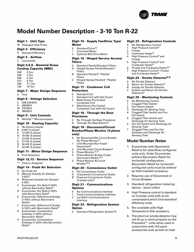
Digit 1 - Unit TypeW Packaged Heat Pump
Digit 2 - EfficiencyS Standard Efficiency
Digit 3 - AirflowC Convertible
Digit 4,5,6 - Nominal Gross Cooling Capacity (MBh)036 3 Ton048 4 Ton060 5 Ton072 6 Ton090 7½ Ton120 10 Ton
Digit 7 - Major Design SequenceA First
Digit 8 - Voltage Selection3 208-230/60/34 460/60/3W 575/60/3K 380/60/3
Digit 9 - Unit ControlsR ReliaTel™ Microprocessor
Digit 10 - Heating Capacity0 No Electric HeaterB 6 kW (3 phase)E 12 kW (3 phase)G 18 kW (3 phase)J 23 kW (3 phase)K 27 kW (3 phase)N 36 kW (3 phase)P 54 kW (3 phase)
Digit 11 - Minor Design SequenceA First Sequence
Digit 12,13 - Service Sequence** Factory Assigned
Digit 14 - Fresh Air Selection0 No Fresh AirA Manual Outside Air Damper
0-50%7
B Motorized Outside Air Damper 0-50%
C Economizer, Dry Bulb 0-100%without Barometric Relief1
D Economizer, Dry Bulb 0-100%with Barometric Relief1
E Economizer, Reference Enthalpy0-100% without BarometricRelief1
F Economizer, Reference Enthalpy0-100% with Barometric Relief1
G Economizer, ComparativeEnthalpy 0-100% withoutBarometric Relief1
H Economizer, ComparativeEnthalpy 0-100% with BarometricRelief1
Digit 15 - Supply Fan/Drive Type/Motor0 Standard Drive10
1 Oversized Motor2 Optional Belt Drive Motor
Digit 16 - Hinged Service Access/Filters0 Standard Panels/Standard FiltersA Hinged Access Panels/Standard
FiltersB Standard Panels/2” Pleated
FiltersC Hinged Access Panels/2” Pleated
Filters
Digit 17 - Condenser Coil Protection0 Standard Coil1 Standard Coil with Hail Guard 2 Black Epoxy Pre-Coated
Condenser Coil3 Black Epoxy Pre-Coated
Condenser Coil with Hail Guard
Digit 18 - Through the Base Provisions0 No Through the Base ProvisionsA Through the Base Electric8
Digit 19 - Disconnect/Circuit Breaker/Phase Monitor (3-phase only)0 No Disconnect/No Circuit Breaker
No Phase Monitor11
1 Unit Mounted Non-Fused Disconnect8
2 Unit Mounted Circuit Breaker8
3 Phase Monitor12,8
4 Phase Monitor & Non-FusedDisconnect Switch12,8
5 Phase Monitor & CircuitBreaker12,8
Digit 20 - Convenience Outlet0 No Convenience OutletA Unpowered Convenience OutletB Powered Convenience Outlet
(3 phase only)2
Digit 21 - Communications Options0 No Communications Interface1 Trane Communications Interface2 LonTalk® Communications
Interface
Digit 22 - Refrigeration System Option0 Standard Refrigeration System33
Digit 23 - Refrigeration Controls0 No Refrigeration Control1 High Pressure Control42 Frostat3 Crankcase Heater9
4 High Pressure Control4 andFrostat
5 High Pressure Control4 andCrankcase Heater9
6 Frostat and Crankcase Heater4,9
7 High Pressure Control4, Frostatand Crankcase Heater9
Digit 24 - Smoke Detector4,5
0 No Smoke DetectorA Return Air Smoke Detector6
B Supply Air Smoke DetectorC Supply and Return Air Smoke
Detectors6
Digit 25 - Monitoring Controls0 No Monitoring Control1 Clogged Filter Switch2 Fan Failure Switch3 Discharge Air Sensing Tube4 Clogged Filter Switch and Fan
Fail Switch5 Clogged Filter Switch and
Discharge Air Sensing Tube6 Fan Fail Switch and Discharge Air
Sensing Tube7 Clogged Filter and Fan Fail
Switches and Discharge AirSensing Tube
Model Number Notes
1. Economizer with Barometric Relief is for downflow configured units only. Order Economizer without Barometric Relief for horizontal configuration. Barometric Relief for horizontal configured units must be ordered as field installed accessory.
2. Requires use of Disconnect or Circuit Breaker.
3. Standard refrigeration metering device – short orifice.
4. High Pressure control is standard on 3-phase units with scroll compressors and in 3 ton standard efficiency units.
5. Not available with High Temperature Stat accessory.
6. The return air smoke detector may not fit up or work properly on the Precedent™ units when used in conjunction with 3rd party accessories such as bolt on heat
Model Number Description - 3-10 Ton R-22
20 PKGP-PRC003-EN
Model Number Description - 3-10 Ton R-22
wheels, economizers and power exhaust. Do not order the return air smoke detectors when using this type of accessory.
7. The manual outside air damper will ship factory supplied within the unit, but must be field installed.
8. Through the base electric required when ordering disconnect/circuit breaker options.
9. Crankcase heaters are standard on 3 ton standard efficiency and 7.5 ton single compressor units.
10. Direct Drive (3-5 tons); Belt Drive (6-10 tons)
11. Phase Monitor standard on 3-5 ton Direct Drive Indoor Motor.
12. Available on 3-10 ton Belt Drive Indoor Motors.
PKGP-PRC003-EN 21
General Data
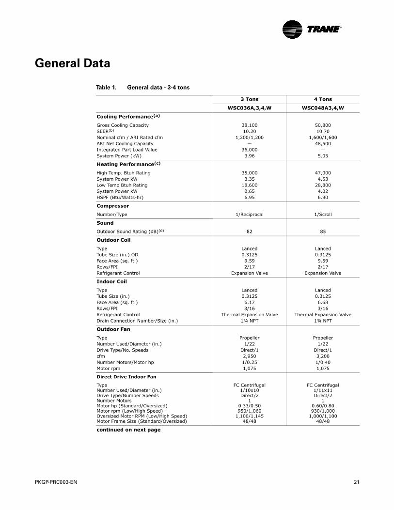
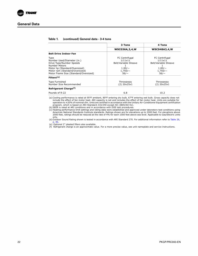
Table 1. General data - 3-4 tons
3 Tons 4 Tons
WSC036A,3,4,W WSC048A3,4,W
Cooling Performance(a)
Gross Cooling CapacitySEER(b)
Nominal cfm / ARI Rated cfmARI Net Cooling CapacityIntegrated Part Load ValueSystem Power (kW)
38,10010.20
1,200/1,200—
36,0003.96
50,80010.70
1,600/1,60048,500
—5.05
Heating Performance(c)
High Temp. Btuh RatingSystem Power kWLow Temp Btuh RatingSystem Power kWHSPF (Btu/Watts-hr)
35,0003.35
18,6002.656.95
47,0004.53
28,8004.026.90
Compressor
Number/Type 1/Reciprocal 1/Scroll
Sound
Outdoor Sound Rating (dB)(d) 82 85
Outdoor Coil
TypeTube Size (in.) ODFace Area (sq. ft.)Rows/FPIRefrigerant Control
Lanced0.31259.592/17
Expansion Valve
Lanced0.31259.592/17
Expansion Valve
Indoor Coil
TypeTube Size (in.)Face Area (sq. ft.)Rows/FPIRefrigerant ControlDrain Connection Number/Size (in.)
Lanced0.31256.173/16
Thermal Expansion Valve1¾ NPT
Lanced0.31256.683/16
Thermal Expansion Valve1¾ NPT
Outdoor Fan
TypeNumber Used/Diameter (in.)Drive Type/No. SpeedscfmNumber Motors/Motor hpMotor rpm
Propeller1/22
Direct/12,9501/0.251,075
Propeller1/22
Direct/13,2001/0.401,075
Direct Drive Indoor Fan
TypeNumber Used/Diameter (in.)Drive Type/Number SpeedsNumber MotorsMotor hp (Standard/Oversized)Motor rpm (Low/High Speed)Oversized Motor RPM (Low/High Speed)Motor Frame Size (Standard/Oversized)
FC Centrifugal1/10x10Direct/2
10.33/0.50950/1,060
1,100/1,14548/48
FC Centrifugal1/11x11Direct/2
10.60/0.80930/1,000
1,000/1,10048/48
continued on next page
22 PKGP-PRC003-EN
General Data
Belt Drive Indoor Fan
TypeNumber Used/Diameter (in.)Drive Type/Number SpeedsNumber MotorsMotor hp (Standard/Oversized)Motor rpm (Standard/Oversized)Motor Frame Size (Standard/Oversized)
FC Centrifugal1/11x11
Belt/Variable Sheave1
1.00/—1,750/—
56/—
FC Centrifugal1/11x11
Belt/Variable Sheave1
1.00/—1,750/—
56/—
Filters(e)
Type FurnishedNumber Size Recommended
Throwaway(2) 20x25x1
Throwaway(2) 20x25x1
Refrigerant Charge(f)
Pounds of R-22 6.8 10.2
(a) Cooling performance is rated at 95°F ambient, 80°F entering dry bulb, 67°F entering wet bulb. Gross capacity does not include the effect of fan motor heat. ARI capacity is net and includes the effect of fan motor heat. Units are suitable for operation to ±20% of nominal cfm. Units are certified in accordance with the Unitary Air-Conditioner Equipment certification program, which is based on ARI Standard 210/240 except AK (380V/60 Hz).
(b) SEER is rated at ARI conditions and in accordance with DOE test procedures.(c) Heating performance limit settings and rating data were established and approved under laboratory test conditions using
American National Standards Institute standards. Ratings shown are for elevations up to 2000 feet. For elevations above 2000 feet, ratings should be reduced at the rate of 4% for each 1000 feet above sea level. Applicable to Gas/Electric units only.
(d) Outdoor Sound Rating shown is tested in accordance with ARI Standard 270. For additional information refer to Table 26, p. 46.
(e) Optional 2” pleated filters also available.(f) Refrigerant charge is an approximate value. For a more precise value, see unit nameplate and service instructions.
Table 1. (continued) General data - 3-4 tons
3 Tons 4 Tons
WSC036A,3,4,W WSC048A3,4,W
PKGP-PRC003-EN 23
General Data
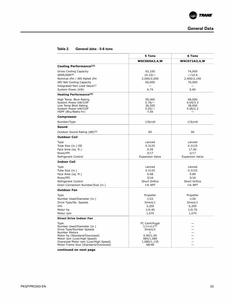
Table 2. General data - 5-6 tons
5 Tons 6 Tons
WSC060A3,4,W WSC072A3,4,W
Cooling Performance(a)
Gross Cooling CapacitySEER/EER(b)
Nominal cfm / ARI Rated cfmARI Net Cooling CapacityIntegrated Part Load Value(c)
System Power (kW)
63,10010.10/—
2,000/2,00060,000
—6.74
74,000—/10.6
2,400/2,10070,000
—6.60
Heating Performance(d)
High Temp. Btuh RatingSystem Power kW/COPLow Temp Btuh RatingSystem Power kW/COPHSPF (Btu/Watts-hr)
59,0005.76/—36,2005.05/—
7.00
68,0006.04/3.338,000
5.06/2.2—
Compressor
Number/Type 1/Scroll 1/Scroll
Sound
Outdoor Sound Rating (dB)(e) 85 90
Outdoor Coil
TypeTube Size (in.) ODFace Area (sq. ft.)Rows/FPIRefrigerant Control
Lanced0.31259.593/17
Expansion Valve
Lanced0.312517.002/17
Expansion Valve
Indoor Coil
TypeTube Size (in.)Face Area (sq. ft.)Rows/FPIRefrigerant ControlDrain Connection Number/Size (in.)
Lanced0.31256.683/16
Short Orifice1¾ NPT
Lanced0.31259.893/16
Short Orifice1¾ NPT
Outdoor Fan
TypeNumber Used/Diameter (in.)Drive Type/No. SpeedscfmMotor hpMotor rpm
Propeller1/22
Direct/13,2001/0.401,075
Propeller1/26
Direct/16,2001/0.701,075
Direct Drive Indoor Fan
TypeNumber Used/Diameter (in.)Drive Type/Number SpeedsNumber MotorsMotor hp (Standard/Oversized)Motor rpm (Low/High Speed)Oversized Motor rpm (Low/High Speed)Motor Frame Size (Standard/Oversized)
FC Centrifugal1/11x11(f)
Direct/21
0.90/1.00985/1,080
1,080/1,13548/48
————————
continued on next page
24 PKGP-PRC003-EN
General Data
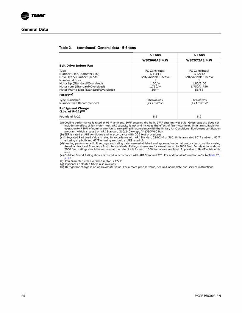
Belt Drive Indoor Fan
TypeNumber Used/Diameter (in.)Drive Type/Number SpeedsNumber MotorsMotor hp (Standard/Oversized)Motor rpm (Standard/Oversized)Motor Frame Size (Standard/Oversized)
FC Centrifugal1/11x11
Belt/Variable Sheave1
1.00/—1,750/—
56/—
FC Centrifugal1/12x12
Belt/Variable Sheave1
1.00/2.001,750/1,750
56/56
Filters(g)
Type FurnishedNumber Size Recommended
Throwaway(2) 20x25x1
Throwaway(4) 16x25x2
Refrigerant Charge (Lbs. of R-22)(h)
Pounds of R-22 8.5 8.2
(a) Cooling performance is rated at 95°F ambient, 80°F entering dry bulb, 67°F entering wet bulb. Gross capacity does not include the effect of fan motor heat. ARI capacity is net and includes the effect of fan motor heat. Units are suitable for operation to ±20% of nominal cfm. Units are certified in accordance with the Unitary Air-Conditioner Equipment certification program, which is based on ARI Standard 210/240 except AK (380V/60 Hz).
(b) EER is rated at ARI conditions and in accordance with DOE test procedures.(c) Integrated Part Load Value is rated in accordance with ARI Standard 210/240 or 360. Units are rated 80°F ambient, 80°F
entering dry bulb and 67°F entering wet bulb at ARI rated cfm.(d) Heating performance limit settings and rating data were established and approved under laboratory test conditions using
American National Standards Institute standards. Ratings shown are for elevations up to 2000 feet. For elevations above 2000 feet, ratings should be reduced at the rate of 4% for each 1000 feet above sea level. Applicable to Gas/Electric units only.
(e) Outdoor Sound Rating shown is tested in accordance with ARI Standard 270. For additional information refer to Table 26, p. 46.
(f) Fan Diameter with oversized motor is 12x11.(g) Optional 2” pleated filters also available.(h) Refrigerant charge is an approximate value. For a more precise value, see unit nameplate and service instructions.
Table 2. (continued) General data - 5-6 tons
5 Tons 6 Tons
WSC060A3,4,W WSC072A3,4,W
PKGP-PRC003-EN 25
General Data
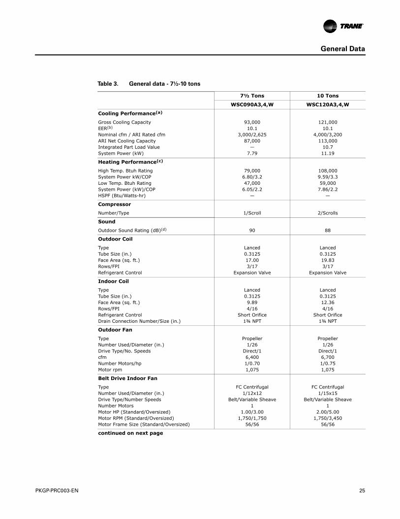
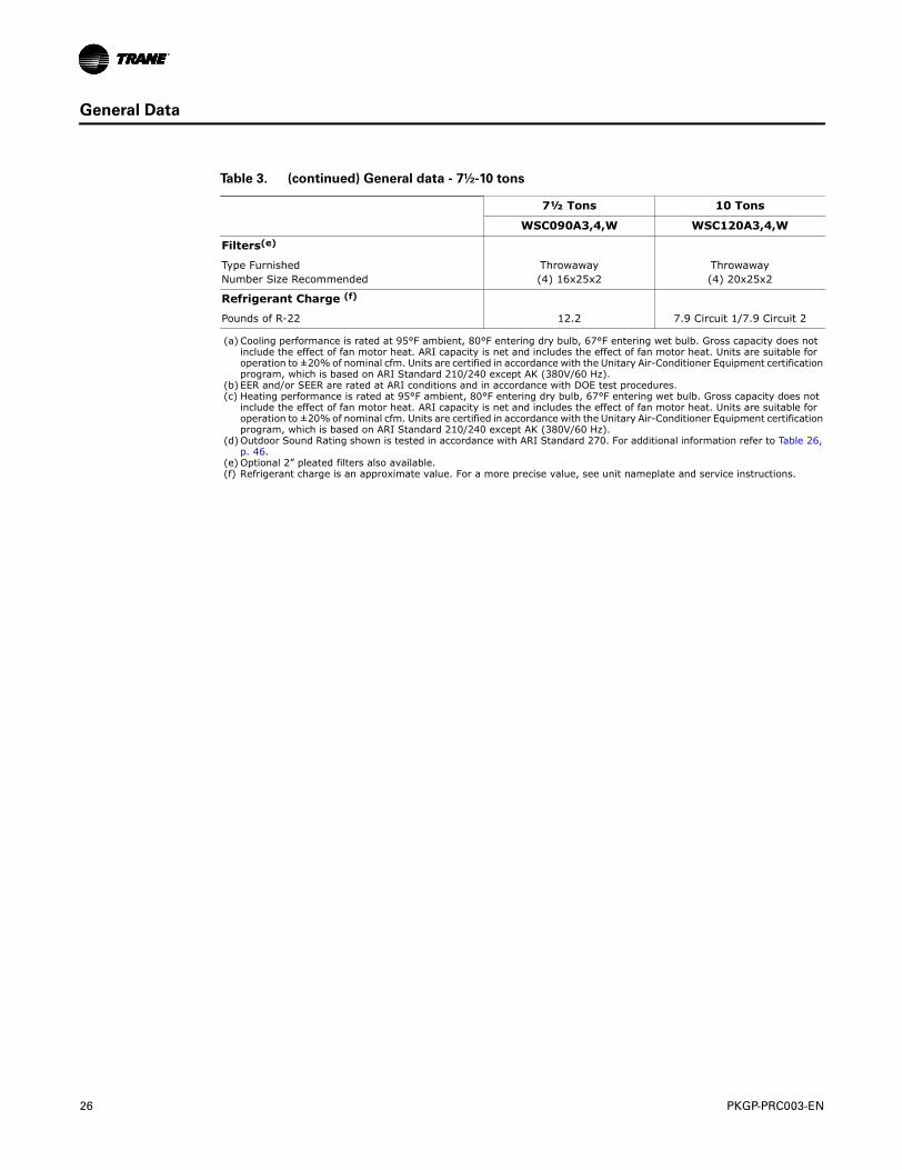
Table 3. General data - 7½-10 tons
7½ Tons 10 Tons
WSC090A3,4,W WSC120A3,4,W
Cooling Performance(a)
Gross Cooling CapacityEER(b)
Nominal cfm / ARI Rated cfmARI Net Cooling CapacityIntegrated Part Load ValueSystem Power (kW)
93,00010.1
3,000/2,62587,000
—7.79
121,00010.1
4,000/3,200113,000
10.711.19
Heating Performance(c)
High Temp. Btuh RatingSystem Power kW/COPLow Temp. Btuh RatingSystem Power (kW)/COPHSPF (Btu/Watts-hr)
79,0006.80/3.247,000
6.05/2.2—
108,0009.59/3.359,000
7.86/2.2—
Compressor
Number/Type 1/Scroll 2/Scrolls
Sound
Outdoor Sound Rating (dB)(d) 90 88
Outdoor Coil
TypeTube Size (in.)Face Area (sq. ft.)Rows/FPIRefrigerant Control
Lanced0.312517.003/17
Expansion Valve
Lanced0.312519.833/17
Expansion Valve
Indoor Coil
TypeTube Size (in.)Face Area (sq. ft.)Rows/FPIRefrigerant ControlDrain Connection Number/Size (in.)
Lanced0.31259.894/16
Short Orifice1¾ NPT
Lanced0.312512.364/16
Short Orifice1¾ NPT
Outdoor Fan
TypeNumber Used/Diameter (in.)Drive Type/No. SpeedscfmNumber Motors/hpMotor rpm
Propeller1/26
Direct/16,4001/0.701,075
Propeller1/26
Direct/16,7001/0.751,075
Belt Drive Indoor Fan
TypeNumber Used/Diameter (in.)Drive Type/Number SpeedsNumber MotorsMotor HP (Standard/Oversized)Motor RPM (Standard/Oversized)Motor Frame Size (Standard/Oversized)
FC Centrifugal1/12x12
Belt/Variable Sheave1
1.00/3.001,750/1,750
56/56
FC Centrifugal1/15x15
Belt/Variable Sheave1
2.00/5.001,750/3,450
56/56
continued on next page
26 PKGP-PRC003-EN
General Data
Filters(e)
Type FurnishedNumber Size Recommended
Throwaway(4) 16x25x2
Throwaway(4) 20x25x2
Refrigerant Charge (f)
Pounds of R-22 12.2 7.9 Circuit 1/7.9 Circuit 2
(a) Cooling performance is rated at 95°F ambient, 80°F entering dry bulb, 67°F entering wet bulb. Gross capacity does not include the effect of fan motor heat. ARI capacity is net and includes the effect of fan motor heat. Units are suitable for operation to ±20% of nominal cfm. Units are certified in accordance with the Unitary Air-Conditioner Equipment certification program, which is based on ARI Standard 210/240 except AK (380V/60 Hz).
(b) EER and/or SEER are rated at ARI conditions and in accordance with DOE test procedures.(c) Heating performance is rated at 95°F ambient, 80°F entering dry bulb, 67°F entering wet bulb. Gross capacity does not
include the effect of fan motor heat. ARI capacity is net and includes the effect of fan motor heat. Units are suitable for operation to ±20% of nominal cfm. Units are certified in accordance with the Unitary Air-Conditioner Equipment certification program, which is based on ARI Standard 210/240 except AK (380V/60 Hz).
(d) Outdoor Sound Rating shown is tested in accordance with ARI Standard 270. For additional information refer to Table 26, p. 46.
(e) Optional 2” pleated filters also available.(f) Refrigerant charge is an approximate value. For a more precise value, see unit nameplate and service instructions.
Table 3. (continued) General data - 7½-10 tons
7½ Tons 10 Tons
WSC090A3,4,W WSC120A3,4,W
PKGP-PRC003-EN 27
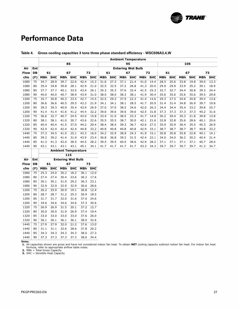
Performance Data
Table 4. Gross cooling capacities 3 tons three phase standard efficiency - WSC036A3,4,W
Ambient Temperature
85 95 105
Air Ent Entering Wet Bulb
Flow DB 61 67 73 61 67 73 61 67 73
cfm (F) MBh SHC MBh SHC MBh SHC MBh SHC MBh SHC MBh SHC MBh SHC MBh SHC MBh SHC1080 75 34.7 28.9 39.7 22.6 42.4 15.3 31.6 27.3 37.1 21.4 41.0 14.4 28.5 25.6 33.8 19.8 39.0 13.3
1080 80 35.4 34.8 39.8 28.1 42.9 21.0 32.5 32.5 37.2 26.8 41.3 20.0 29.9 29.9 33.9 25.2 39.1 18.9
1080 85 37.7 37.7 40.1 33.5 43.4 26.1 35.3 35.3 37.6 32.4 41.5 25.3 32.7 32.7 34.4 30.8 39.3 24.4
1080 90 40.0 40.0 40.7 38.9 43.9 31.0 38.0 38.0 38.3 38.1 41.9 30.4 35.6 35.6 35.6 35.6 39.5 29.8
1200 75 35.7 30.8 40.3 23.5 42.7 15.5 32.5 29.2 37.9 22.3 41.4 14.6 29.3 27.5 34.6 20.8 39.4 13.6
1200 80 36.6 36.6 40.5 29.5 43.3 21.9 34.1 34.1 38.1 28.5 41.7 20.9 31.4 31.4 34.8 26.9 39.7 19.8
1200 85 39.3 39.3 40.9 35.4 43.9 26.9 37.0 37.0 38.5 34.6 42.0 26.3 34.4 34.4 35.4 33.2 39.8 25.7
1200 90 41.4 41.4 41.6 41.2 44.4 32.2 39.6 39.6 39.6 39.6 42.5 31.8 37.3 37.3 37.3 37.3 40.2 31.6
1320 75 36.6 32.7 40.7 24.5 43.0 15.8 33.4 31.0 38.5 23.3 41.7 14.9 30.2 29.4 35.3 21.8 39.8 13.8
1320 80 38.1 38.1 41.0 30.7 43.6 22.6 35.5 35.5 38.7 30.0 42.1 21.6 32.8 32.8 35.6 28.6 40.1 20.6
1320 85 40.4 40.4 41.5 37.0 44.2 29.4 38.4 38.4 39.3 36.7 42.6 27.5 35.9 35.9 36.4 35.5 40.3 26.9
1320 90 42.4 42.4 42.4 42.4 44.8 33.2 40.8 40.8 40.8 40.8 42.9 33.1 38.7 38.7 38.7 38.7 40.8 33.2
1440 75 37.3 34.5 41.0 25.1 43.3 16.0 34.2 32.9 38.9 24.3 41.9 15.1 30.8 30.8 35.8 22.8 40.1 14.1
1440 80 39.2 39.2 41.4 31.9 43.9 23.4 36.8 36.8 39.2 31.5 42.4 22.1 34.0 34.0 36.2 30.2 40.4 21.4
1440 85 41.3 41.3 42.0 38.5 44.5 28.2 39.5 39.5 40.0 38.6 42.9 28.2 37.1 37.1 37.1 37.1 40.7 28.0
1440 90 43.1 43.1 43.1 43.1 45.1 34.1 41.7 41.7 41.7 41.7 43.3 34.3 39.7 39.7 39.7 39.7 41.3 34.7
Ambient Temperature
115
Air Ent Entering Wet Bulb
Flow DB 61 67 73
cfm (F) MBh SHC MBh SHC MBh SHC1080 75 25.3 24.0 30.2 18.2 36.1 12.0
1080 80 27.4 27.4 30.4 23.6 36.2 17.6
1080 85 30.1 30.1 31.0 29.2 36.3 23.1
1080 90 32.9 32.9 32.9 32.9 36.6 28.6
1200 75 26.2 25.9 30.9 19.1 36.8 12.4
1200 80 28.7 28.7 31.2 25.3 36.9 18.5
1200 85 31.7 31.7 32.0 31.6 37.0 24.6
1200 90 34.6 34.6 34.6 34.6 37.3 30.6
1320 75 26.9 26.9 31.5 20.1 37.2 12.7
1320 80 30.0 30.0 31.9 26.9 37.4 19.4
1320 85 33.0 33.0 33.0 33.0 37.6 26.0
1320 90 36.1 36.1 36.1 36.1 38.0 32.6
1440 75 27.9 27.9 32.0 21.2 37.6 13.0
1440 80 31.1 31.1 32.6 28.6 37.8 20.2
1440 85 34.3 34.3 34.3 34.3 38.0 27.3
1440 90 37.3 37.3 37.3 37.3 38.6 34.4
Notes:
1. All capacities shown are gross and have not considered indoor fan heat. To obtain NET cooling capacity subtract indoor fan heat. For indoor fan heat formula, refer to appropriate airflow table notes.
2. MBh = Total Gross Capacity 3. SHC = Sensible Heat Capacity
28 PKGP-PRC003-EN
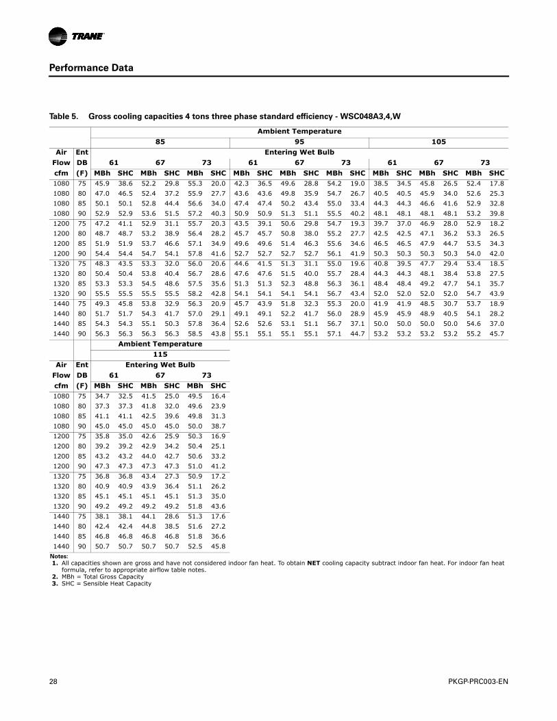
Performance Data
Table 5. Gross cooling capacities 4 tons three phase standard efficiency - WSC048A3,4,W
Ambient Temperature
85 95 105
Air Ent Entering Wet Bulb
Flow DB 61 67 73 61 67 73 61 67 73
cfm (F) MBh SHC MBh SHC MBh SHC MBh SHC MBh SHC MBh SHC MBh SHC MBh SHC MBh SHC1080 75 45.9 38.6 52.2 29.8 55.3 20.0 42.3 36.5 49.6 28.8 54.2 19.0 38.5 34.5 45.8 26.5 52.4 17.8
1080 80 47.0 46.5 52.4 37.2 55.9 27.7 43.6 43.6 49.8 35.9 54.7 26.7 40.5 40.5 45.9 34.0 52.6 25.3
1080 85 50.1 50.1 52.8 44.4 56.6 34.0 47.4 47.4 50.2 43.4 55.0 33.4 44.3 44.3 46.6 41.6 52.9 32.8
1080 90 52.9 52.9 53.6 51.5 57.2 40.3 50.9 50.9 51.3 51.1 55.5 40.2 48.1 48.1 48.1 48.1 53.2 39.8
1200 75 47.2 41.1 52.9 31.1 55.7 20.3 43.5 39.1 50.6 29.8 54.7 19.3 39.7 37.0 46.9 28.0 52.9 18.2
1200 80 48.7 48.7 53.2 38.9 56.4 28.2 45.7 45.7 50.8 38.0 55.2 27.7 42.5 42.5 47.1 36.2 53.3 26.5
1200 85 51.9 51.9 53.7 46.6 57.1 34.9 49.6 49.6 51.4 46.3 55.6 34.6 46.5 46.5 47.9 44.7 53.5 34.3
1200 90 54.4 54.4 54.7 54.1 57.8 41.6 52.7 52.7 52.7 52.7 56.1 41.9 50.3 50.3 50.3 50.3 54.0 42.0
1320 75 48.3 43.5 53.3 32.0 56.0 20.6 44.6 41.5 51.3 31.1 55.0 19.6 40.8 39.5 47.7 29.4 53.4 18.5
1320 80 50.4 50.4 53.8 40.4 56.7 28.6 47.6 47.6 51.5 40.0 55.7 28.4 44.3 44.3 48.1 38.4 53.8 27.5
1320 85 53.3 53.3 54.5 48.6 57.5 35.6 51.3 51.3 52.3 48.8 56.3 36.1 48.4 48.4 49.2 47.7 54.1 35.7
1320 90 55.5 55.5 55.5 55.5 58.2 42.8 54.1 54.1 54.1 54.1 56.7 43.4 52.0 52.0 52.0 52.0 54.7 43.9
1440 75 49.3 45.8 53.8 32.9 56.3 20.9 45.7 43.9 51.8 32.3 55.3 20.0 41.9 41.9 48.5 30.7 53.7 18.9
1440 80 51.7 51.7 54.3 41.7 57.0 29.1 49.1 49.1 52.2 41.7 56.0 28.9 45.9 45.9 48.9 40.5 54.1 28.2
1440 85 54.3 54.3 55.1 50.3 57.8 36.4 52.6 52.6 53.1 51.1 56.7 37.1 50.0 50.0 50.0 50.0 54.6 37.0
1440 90 56.3 56.3 56.3 56.3 58.5 43.8 55.1 55.1 55.1 55.1 57.1 44.7 53.2 53.2 53.2 53.2 55.2 45.7
Ambient Temperature
115
Air Ent Entering Wet Bulb
Flow DB 61 67 73
cfm (F) MBh SHC MBh SHC MBh SHC1080 75 34.7 32.5 41.5 25.0 49.5 16.4
1080 80 37.3 37.3 41.8 32.0 49.6 23.9
1080 85 41.1 41.1 42.5 39.6 49.8 31.3
1080 90 45.0 45.0 45.0 45.0 50.0 38.7
1200 75 35.8 35.0 42.6 25.9 50.3 16.9
1200 80 39.2 39.2 42.9 34.2 50.4 25.1
1200 85 43.2 43.2 44.0 42.7 50.6 33.2
1200 90 47.3 47.3 47.3 47.3 51.0 41.2
1320 75 36.8 36.8 43.4 27.3 50.9 17.2
1320 80 40.9 40.9 43.9 36.4 51.1 26.2
1320 85 45.1 45.1 45.1 45.1 51.3 35.0
1320 90 49.2 49.2 49.2 49.2 51.8 43.6
1440 75 38.1 38.1 44.1 28.6 51.3 17.6
1440 80 42.4 42.4 44.8 38.5 51.6 27.2
1440 85 46.8 46.8 46.8 46.8 51.8 36.6
1440 90 50.7 50.7 50.7 50.7 52.5 45.8
Notes:
1. All capacities shown are gross and have not considered indoor fan heat. To obtain NET cooling capacity subtract indoor fan heat. For indoor fan heat formula, refer to appropriate airflow table notes.
2. MBh = Total Gross Capacity 3. SHC = Sensible Heat Capacity
PKGP-PRC003-EN 29
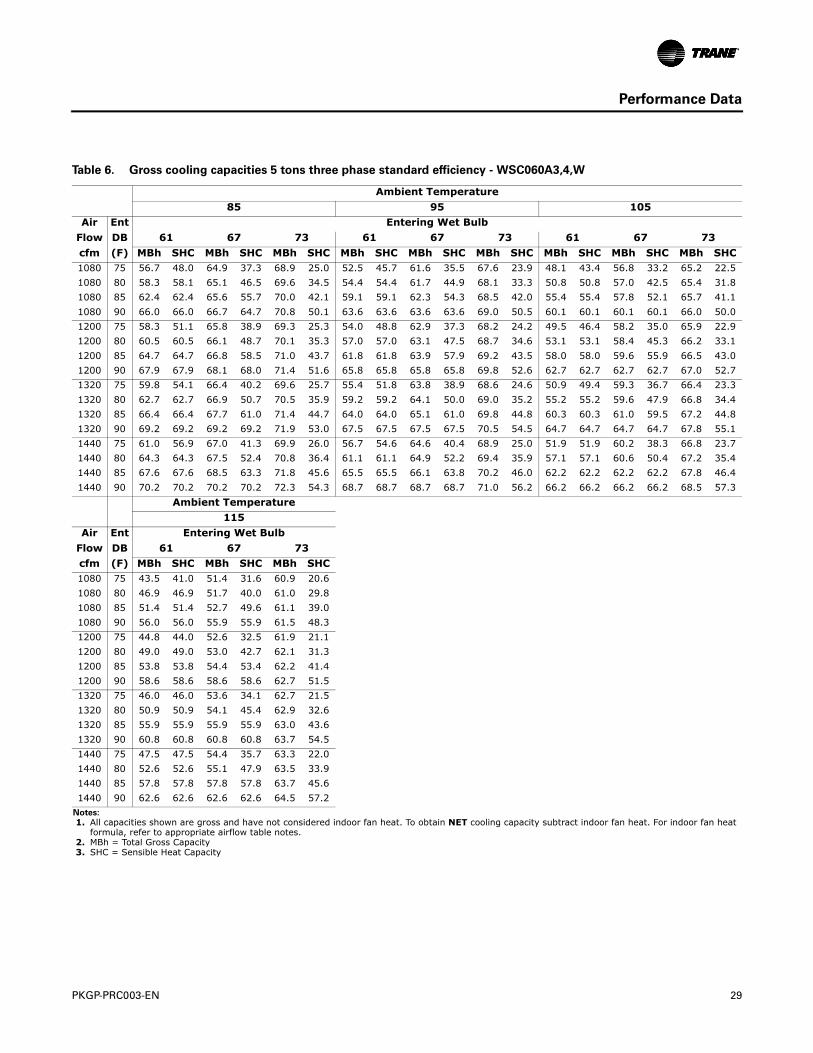
Performance Data
Table 6. Gross cooling capacities 5 tons three phase standard efficiency - WSC060A3,4,W
Ambient Temperature
85 95 105
Air Ent Entering Wet Bulb
Flow DB 61 67 73 61 67 73 61 67 73
cfm (F) MBh SHC MBh SHC MBh SHC MBh SHC MBh SHC MBh SHC MBh SHC MBh SHC MBh SHC1080 75 56.7 48.0 64.9 37.3 68.9 25.0 52.5 45.7 61.6 35.5 67.6 23.9 48.1 43.4 56.8 33.2 65.2 22.5
1080 80 58.3 58.1 65.1 46.5 69.6 34.5 54.4 54.4 61.7 44.9 68.1 33.3 50.8 50.8 57.0 42.5 65.4 31.8
1080 85 62.4 62.4 65.6 55.7 70.0 42.1 59.1 59.1 62.3 54.3 68.5 42.0 55.4 55.4 57.8 52.1 65.7 41.1
1080 90 66.0 66.0 66.7 64.7 70.8 50.1 63.6 63.6 63.6 63.6 69.0 50.5 60.1 60.1 60.1 60.1 66.0 50.0
1200 75 58.3 51.1 65.8 38.9 69.3 25.3 54.0 48.8 62.9 37.3 68.2 24.2 49.5 46.4 58.2 35.0 65.9 22.9
1200 80 60.5 60.5 66.1 48.7 70.1 35.3 57.0 57.0 63.1 47.5 68.7 34.6 53.1 53.1 58.4 45.3 66.2 33.1
1200 85 64.7 64.7 66.8 58.5 71.0 43.7 61.8 61.8 63.9 57.9 69.2 43.5 58.0 58.0 59.6 55.9 66.5 43.0
1200 90 67.9 67.9 68.1 68.0 71.4 51.6 65.8 65.8 65.8 65.8 69.8 52.6 62.7 62.7 62.7 62.7 67.0 52.7
1320 75 59.8 54.1 66.4 40.2 69.6 25.7 55.4 51.8 63.8 38.9 68.6 24.6 50.9 49.4 59.3 36.7 66.4 23.3
1320 80 62.7 62.7 66.9 50.7 70.5 35.9 59.2 59.2 64.1 50.0 69.0 35.2 55.2 55.2 59.6 47.9 66.8 34.4
1320 85 66.4 66.4 67.7 61.0 71.4 44.7 64.0 64.0 65.1 61.0 69.8 44.8 60.3 60.3 61.0 59.5 67.2 44.8
1320 90 69.2 69.2 69.2 69.2 71.9 53.0 67.5 67.5 67.5 67.5 70.5 54.5 64.7 64.7 64.7 64.7 67.8 55.1
1440 75 61.0 56.9 67.0 41.3 69.9 26.0 56.7 54.6 64.6 40.4 68.9 25.0 51.9 51.9 60.2 38.3 66.8 23.7
1440 80 64.3 64.3 67.5 52.4 70.8 36.4 61.1 61.1 64.9 52.2 69.4 35.9 57.1 57.1 60.6 50.4 67.2 35.4
1440 85 67.6 67.6 68.5 63.3 71.8 45.6 65.5 65.5 66.1 63.8 70.2 46.0 62.2 62.2 62.2 62.2 67.8 46.4
1440 90 70.2 70.2 70.2 70.2 72.3 54.3 68.7 68.7 68.7 68.7 71.0 56.2 66.2 66.2 66.2 66.2 68.5 57.3
Ambient Temperature
115
Air Ent Entering Wet Bulb
Flow DB 61 67 73
cfm (F) MBh SHC MBh SHC MBh SHC1080 75 43.5 41.0 51.4 31.6 60.9 20.6
1080 80 46.9 46.9 51.7 40.0 61.0 29.8
1080 85 51.4 51.4 52.7 49.6 61.1 39.0
1080 90 56.0 56.0 55.9 55.9 61.5 48.3
1200 75 44.8 44.0 52.6 32.5 61.9 21.1
1200 80 49.0 49.0 53.0 42.7 62.1 31.3
1200 85 53.8 53.8 54.4 53.4 62.2 41.4
1200 90 58.6 58.6 58.6 58.6 62.7 51.5
1320 75 46.0 46.0 53.6 34.1 62.7 21.5
1320 80 50.9 50.9 54.1 45.4 62.9 32.6
1320 85 55.9 55.9 55.9 55.9 63.0 43.6
1320 90 60.8 60.8 60.8 60.8 63.7 54.5
1440 75 47.5 47.5 54.4 35.7 63.3 22.0
1440 80 52.6 52.6 55.1 47.9 63.5 33.9
1440 85 57.8 57.8 57.8 57.8 63.7 45.6
1440 90 62.6 62.6 62.6 62.6 64.5 57.2
Notes:
1. All capacities shown are gross and have not considered indoor fan heat. To obtain NET cooling capacity subtract indoor fan heat. For indoor fan heat formula, refer to appropriate airflow table notes.
2. MBh = Total Gross Capacity 3. SHC = Sensible Heat Capacity

30 PKGP-PRC003-EN
Performance Data
Table 7. Gross cooling capacities 6 tons three phase standard efficiency - WSC072A3,4,W
Ambient Temperature
85 95 105
Air Ent Entering Wet Bulb
Flow DB 61 67 73 61 67 73 61 67 73
cfm (F) MBh SHC MBh SHC MBh SHC MBh SHC MBh SHC MBh SHC MBh SHC MBh SHC MBh SHC1080 75 67.2 58.4 75.7 44.4 79.1 29.2 62.2 56.0 72.2 43.0 78.1 28.2 57.0 53.5 66.8 40.7 75.9 27.0
1080 80 69.3 69.3 76.0 55.5 80.0 40.6 65.3 65.3 72.5 54.6 78.6 39.6 61.0 61.0 67.3 52.2 76.2 38.3
1080 85 74.1 74.1 76.6 66.2 80.8 49.0 70.7 70.7 73.4 66.1 79.4 50.9 66.5 66.5 68.4 63.8 76.4 49.6
1080 90 77.4 77.4 77.8 76.6 81.7 58.2 75.2 75.2 75.2 75.2 80.1 59.8 71.9 71.9 71.9 71.9 77.0 59.9
1200 75 69.1 62.4 76.5 46.4 79.5 29.7 64.1 59.9 73.6 45.2 78.5 28.7 58.8 57.4 68.4 43.0 76.5 27.4
1200 80 72.3 72.3 77.0 57.9 80.3 42.3 68.3 68.3 74.0 57.8 79.1 41.2 63.9 63.9 69.0 55.7 76.9 40.0
1200 85 76.2 76.2 77.8 69.3 81.3 50.1 73.7 73.7 74.9 70.1 79.9 51.0 69.7 69.7 70.4 68.7 77.3 51.5
1200 90 79.1 79.1 79.1 79.1 82.2 59.7 77.4 77.4 77.4 77.4 80.7 61.6 74.6 74.6 74.6 74.6 78.0 62.8
1320 75 70.7 66.2 77.1 48.4 79.8 30.1 65.8 63.8 74.5 47.2 78.9 29.1 60.5 60.5 69.6 45.2 77.0 27.9
1320 80 74.4 74.4 77.7 60.0 80.6 43.9 70.9 70.9 75.0 60.7 79.4 42.9 66.5 66.5 70.3 59.1 77.4 41.7
1320 85 77.8 77.8 78.7 71.9 81.6 51.0 75.7 75.7 76.3 73.7 80.3 52.3 72.4 72.4 72.4 72.4 78.0 53.3
1320 90 80.1 80.1 80.1 80.1 82.6 61.0 78.9 78.9 78.9 78.9 81.2 63.3 76.5 76.5 76.5 76.5 78.8 65.3
1440 75 72.2 70.0 77.6 48.8 80.0 30.5 67.2 67.2 75.2 49.0 79.1 29.5 62.5 62.5 70.6 47.3 77.3 28.4
1440 80 75.9 75.9 78.3 61.8 81.0 41.5 73.2 73.2 75.9 63.3 80.1 42.2 68.8 68.8 71.5 62.4 78.0 42.6
1440 85 78.8 78.8 79.3 74.1 81.9 51.9 77.1 77.1 77.4 76.8 80.7 53.4 74.2 74.2 74.3 74.3 78.5 55.0
1440 90 80.9 80.9 80.9 80.9 82.9 62.2 79.9 79.9 79.9 79.9 81.6 64.8 77.9 77.9 77.9 77.9 79.4 67.5
Ambient Temperature
115
Air Ent Entering Wet Bulb
Flow DB 61 67 73
cfm (F) MBh SHC MBh SHC MBh SHC1080 75 51.7 51.0 60.8 38.2 72.1 25.6
1080 80 56.6 56.6 61.4 49.6 72.2 37.0
1080 85 62.1 62.1 62.8 61.4 72.4 48.2
1080 90 67.7 67.7 67.7 67.7 72.9 59.4
1200 75 53.6 53.6 62.2 40.5 73.1 26.1
1200 80 59.3 59.3 63.0 53.2 73.2 38.7
1200 85 65.2 65.2 65.2 65.2 73.4 51.0
1200 90 70.9 70.9 70.9 70.9 74.2 63.0
1320 75 55.7 55.7 63.4 42.7 73.8 26.5
1320 80 61.7 61.7 64.5 56.7 74.0 40.3
1320 85 67.9 67.9 67.9 67.9 74.4 53.6
1320 90 73.2 73.2 73.2 73.2 75.3 66.4
1440 75 57.6 57.6 64.5 44.8 74.3 27.0
1440 80 63.9 63.9 65.8 60.1 74.6 42.0
1440 85 70.0 70.0 70.1 70.1 75.1 55.9
1440 90 74.9 74.9 74.9 74.9 76.2 69.4
Notes:
1. All capacities shown are gross and have not considered indoor fan heat. To obtain NET cooling capacity subtract indoor fan heat. For indoor fan heat formula, refer to appropriate airflow table notes.
2. MBh = Total Gross Capacity 3. SHC = Sensible Heat Capacity
PKGP-PRC003-EN 31
Performance Data
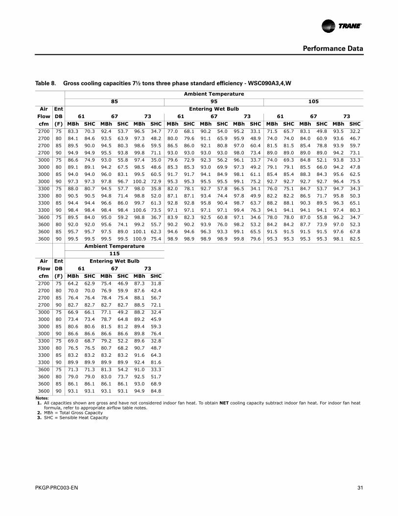
Table 8. Gross cooling capacities 7½ tons three phase standard efficiency - WSC090A3,4,W
Ambient Temperature
85 95 105
Air Ent Entering Wet Bulb
Flow DB 61 67 73 61 67 73 61 67 73
cfm (F) MBh SHC MBh SHC MBh SHC MBh SHC MBh SHC MBh SHC MBh SHC MBh SHC MBh SHC2700 75 83.3 70.3 92.4 53.7 96.5 34.7 77.0 68.1 90.2 54.0 95.2 33.1 71.5 65.7 83.1 49.8 93.5 32.2
2700 80 84.1 84.6 93.5 63.9 97.3 48.2 80.0 79.6 91.1 65.9 95.9 48.9 74.0 74.0 84.0 60.9 93.6 46.7
2700 85 89.5 90.0 94.5 80.3 98.6 59.5 86.5 86.0 92.1 80.8 97.0 60.4 81.5 81.5 85.4 78.8 93.9 59.7
2700 90 94.9 94.9 95.5 93.8 99.8 71.1 93.0 93.0 93.0 93.0 98.0 73.4 89.0 89.0 89.0 89.0 94.2 73.1
3000 75 86.6 74.9 93.0 55.8 97.4 35.0 79.6 72.9 92.3 56.2 96.1 33.7 74.0 69.3 84.8 52.1 93.8 33.3
3000 80 89.1 89.1 94.2 67.5 98.5 48.6 85.3 85.3 93.0 69.9 97.3 49.2 79.1 79.1 85.5 66.0 94.2 47.8
3000 85 94.0 94.0 96.0 83.1 99.5 60.5 91.7 91.7 94.1 84.9 98.1 61.1 85.4 85.4 88.3 84.3 95.6 62.5
3000 90 97.3 97.3 97.8 96.7 100.2 72.9 95.3 95.3 95.5 95.5 99.1 75.2 92.7 92.7 92.7 92.7 96.4 75.5
3300 75 88.0 80.7 94.5 57.7 98.0 35.8 82.0 78.1 92.7 57.8 96.5 34.1 76.0 75.1 84.7 53.7 94.7 34.3
3300 80 90.5 90.5 94.8 71.4 98.8 52.0 87.1 87.1 93.4 74.4 97.8 49.9 82.2 82.2 86.5 71.7 95.8 50.3
3300 85 94.4 94.4 96.6 86.0 99.7 61.3 92.8 92.8 95.8 90.4 98.7 63.7 88.2 88.1 90.3 89.5 96.3 65.1
3300 90 98.4 98.4 98.4 98.4 100.6 73.5 97.1 97.1 97.1 97.1 99.4 76.3 94.1 94.1 94.1 94.1 97.4 80.3
3600 75 89.5 84.0 95.0 59.2 98.8 36.7 83.9 82.3 92.5 60.8 97.1 34.6 78.0 78.0 87.0 55.8 96.2 34.7
3600 80 92.0 92.0 95.6 74.1 99.2 55.7 90.2 90.2 93.9 76.0 98.2 53.2 84.2 84.2 87.7 73.9 97.0 52.3
3600 85 95.7 95.7 97.5 89.0 100.1 62.3 94.6 94.6 96.3 93.3 99.1 65.5 91.5 91.5 91.5 91.5 97.6 67.8
3600 90 99.5 99.5 99.5 99.5 100.9 75.4 98.9 98.9 98.9 98.9 99.8 79.6 95.3 95.3 95.3 95.3 98.1 82.5
Ambient Temperature
115
Air Ent Entering Wet Bulb
Flow DB 61 67 73
cfm (F) MBh SHC MBh SHC MBh SHC2700 75 64.2 62.9 75.4 46.9 87.3 31.8
2700 80 70.0 70.0 76.9 59.9 87.6 42.4
2700 85 76.4 76.4 78.4 75.4 88.1 56.7
2700 90 82.7 82.7 82.7 82.7 88.5 72.1
3000 75 66.9 66.1 77.1 49.2 88.2 32.4
3000 80 73.4 73.4 78.7 64.8 89.2 45.9
3000 85 80.6 80.6 81.5 81.2 89.4 59.3
3000 90 86.6 86.6 86.6 86.6 89.8 76.4
3300 75 69.0 68.7 79.2 52.2 89.6 32.8
3300 80 76.5 76.5 80.7 68.2 90.7 48.7
3300 85 83.2 83.2 83.2 83.2 91.6 64.3
3300 90 89.9 89.9 89.9 89.9 92.4 81.6
3600 75 71.3 71.3 81.3 54.2 91.0 33.3
3600 80 79.0 79.0 83.0 73.7 92.5 51.7
3600 85 86.1 86.1 86.1 86.1 93.0 68.9
3600 90 93.1 93.1 93.1 93.1 94.9 84.8
Notes:
1. All capacities shown are gross and have not considered indoor fan heat. To obtain NET cooling capacity subtract indoor fan heat. For indoor fan heat formula, refer to appropriate airflow table notes.
2. MBh = Total Gross Capacity 3. SHC = Sensible Heat Capacity
32 PKGP-PRC003-EN
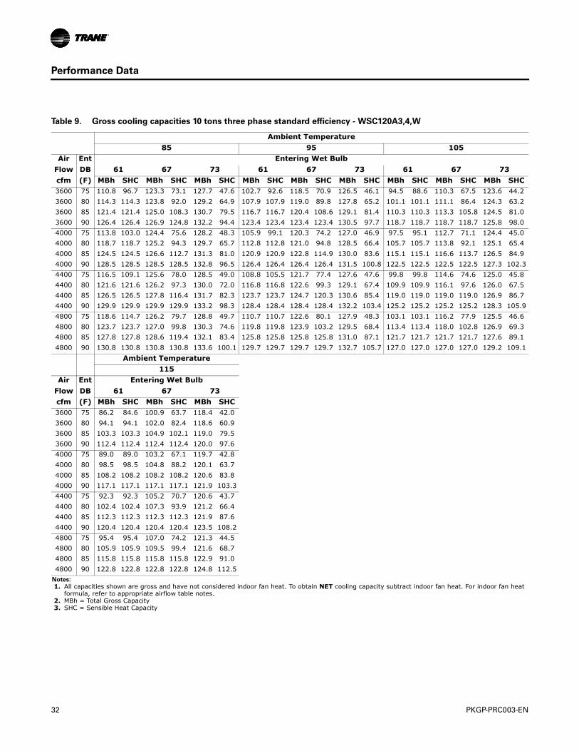
Performance Data
Table 9. Gross cooling capacities 10 tons three phase standard efficiency - WSC120A3,4,W
Ambient Temperature
85 95 105
Air Ent Entering Wet Bulb
Flow DB 61 67 73 61 67 73 61 67 73
cfm (F) MBh SHC MBh SHC MBh SHC MBh SHC MBh SHC MBh SHC MBh SHC MBh SHC MBh SHC3600 75 110.8 96.7 123.3 73.1 127.7 47.6 102.7 92.6 118.5 70.9 126.5 46.1 94.5 88.6 110.3 67.5 123.6 44.2
3600 80 114.3 114.3 123.8 92.0 129.2 64.9 107.9 107.9 119.0 89.8 127.8 65.2 101.1 101.1 111.1 86.4 124.3 63.2
3600 85 121.4 121.4 125.0 108.3 130.7 79.5 116.7 116.7 120.4 108.6 129.1 81.4 110.3 110.3 113.3 105.8 124.5 81.0
3600 90 126.4 126.4 126.9 124.8 132.2 94.4 123.4 123.4 123.4 123.4 130.5 97.7 118.7 118.7 118.7 118.7 125.8 98.0
4000 75 113.8 103.0 124.4 75.6 128.2 48.3 105.9 99.1 120.3 74.2 127.0 46.9 97.5 95.1 112.7 71.1 124.4 45.0
4000 80 118.7 118.7 125.2 94.3 129.7 65.7 112.8 112.8 121.0 94.8 128.5 66.4 105.7 105.7 113.8 92.1 125.1 65.4
4000 85 124.5 124.5 126.6 112.7 131.3 81.0 120.9 120.9 122.8 114.9 130.0 83.6 115.1 115.1 116.6 113.7 126.5 84.9
4000 90 128.5 128.5 128.5 128.5 132.8 96.5 126.4 126.4 126.4 126.4 131.5 100.8 122.5 122.5 122.5 122.5 127.3 102.3
4400 75 116.5 109.1 125.6 78.0 128.5 49.0 108.8 105.5 121.7 77.4 127.6 47.6 99.8 99.8 114.6 74.6 125.0 45.8
4400 80 121.6 121.6 126.2 97.3 130.0 72.0 116.8 116.8 122.6 99.3 129.1 67.4 109.9 109.9 116.1 97.6 126.0 67.5
4400 85 126.5 126.5 127.8 116.4 131.7 82.3 123.7 123.7 124.7 120.3 130.6 85.4 119.0 119.0 119.0 119.0 126.9 86.7
4400 90 129.9 129.9 129.9 129.9 133.2 98.3 128.4 128.4 128.4 128.4 132.2 103.4 125.2 125.2 125.2 125.2 128.3 105.9
4800 75 118.6 114.7 126.2 79.7 128.8 49.7 110.7 110.7 122.6 80.1 127.9 48.3 103.1 103.1 116.2 77.9 125.5 46.6
4800 80 123.7 123.7 127.0 99.8 130.3 74.6 119.8 119.8 123.9 103.2 129.5 68.4 113.4 113.4 118.0 102.8 126.9 69.3
4800 85 127.8 127.8 128.6 119.4 132.1 83.4 125.8 125.8 125.8 125.8 131.0 87.1 121.7 121.7 121.7 121.7 127.6 89.1
4800 90 130.8 130.8 130.8 130.8 133.6 100.1 129.7 129.7 129.7 129.7 132.7 105.7 127.0 127.0 127.0 127.0 129.2 109.1
Ambient Temperature
115
Air Ent Entering Wet Bulb
Flow DB 61 67 73
cfm (F) MBh SHC MBh SHC MBh SHC3600 75 86.2 84.6 100.9 63.7 118.4 42.0
3600 80 94.1 94.1 102.0 82.4 118.6 60.9
3600 85 103.3 103.3 104.9 102.1 119.0 79.5
3600 90 112.4 112.4 112.4 112.4 120.0 97.6
4000 75 89.0 89.0 103.2 67.1 119.7 42.8
4000 80 98.5 98.5 104.8 88.2 120.1 63.7
4000 85 108.2 108.2 108.2 108.2 120.6 83.8
4000 90 117.1 117.1 117.1 117.1 121.9 103.3
4400 75 92.3 92.3 105.2 70.7 120.6 43.7
4400 80 102.4 102.4 107.3 93.9 121.2 66.4
4400 85 112.3 112.3 112.3 112.3 121.9 87.6
4400 90 120.4 120.4 120.4 120.4 123.5 108.2
4800 75 95.4 95.4 107.0 74.2 121.3 44.5
4800 80 105.9 105.9 109.5 99.4 121.6 68.7
4800 85 115.8 115.8 115.8 115.8 122.9 91.0
4800 90 122.8 122.8 122.8 122.8 124.8 112.5
Notes:
1. All capacities shown are gross and have not considered indoor fan heat. To obtain NET cooling capacity subtract indoor fan heat. For indoor fan heat formula, refer to appropriate airflow table notes.
2. MBh = Total Gross Capacity 3. SHC = Sensible Heat Capacity
PKGP-PRC003-EN 33
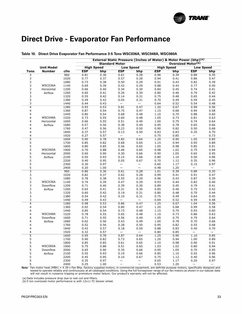
Direct Drive - Evaporator Fan Performance
Table 10. Direct Drive Evaporator Fan Performance 3-5 Tons WSC036A, WSC048A, WSC060A
External Static Pressure (Inches of Water) & Motor Power (bhp)(a)
Standard Motor Oversized Motor(b)
Unit Model High Speed Low Speed High Speed Low SpeedTons Number cfm ESP bhp ESP bhp ESP bhp ESP bhp
3
WSC036AHorizontal
Airflow
960 0.81 0.36 0.61 0.28 0.96 0.39 0.89 0.353 1020 0.77 0.37 0.57 0.28 0.94 0.41 0.86 0.473 1080 0.73 0.38 0.50 0.29 0.91 0.43 0.82 0.393 1140 0.69 0.39 0.42 0.29 0.88 0.44 0.77 0.403 1200 0.66 0.40 0.34 0.30 0.84 0.45 0.74 0.413 1260 0.60 0.41 0.26 0.30 0.80 0.46 0.70 0.423 1320 0.55 0.42 0.14 0.31 0.75 0.48 0.65 0.443 1380 0.49 0.42 0.05 0.31 0.70 0.49 0.59 0.453 1440 0.44 0.43 — — 0.64 0.52 0.54 0.484
WSC048AHorizontal
Airflow
1280 0.93 0.53 0.81 0.47 1.20 0.67 0.99 0.564 1360 0.87 0.54 0.75 0.47 1.15 0.68 0.94 0.584 1440 0.80 0.54 0.68 0.48 1.10 0.70 0.88 0.604 1520 0.73 0.55 0.60 0.48 1.05 0.73 0.81 0.634 1600 0.66 0.55 0.51 0.49 1.00 0.75 0.74 0.644 1680 0.57 0.56 0.38 0.49 0.95 0.78 0.65 0.664 1760 0.47 0.56 0.23 0.50 0.90 0.82 0.50 0.684 1840 0.37 0.57 0.13 0.50 0.83 0.83 0.35 0.704 1920 0.27 0.57 — — 0.75 0.85 — 0.735
WSC060AHorizontal
Airflow
1600 0.90 0.78 0.82 0.64 1.20 0.90 1.05 0.855 1700 0.85 0.82 0.68 0.65 1.15 0.94 0.95 0.895 1800 0.80 0.85 0.56 0.65 1.05 0.98 0.85 0.915 1900 0.70 0.88 0.46 0.65 0.98 1.02 0.75 0.945 2000 0.60 0.90 0.30 0.66 0.90 1.05 0.65 0.955 2100 0.50 0.93 0.14 0.66 0.80 1.10 0.50 0.965 2200 0.40 0.95 0.05 0.67 0.70 1.12 0.35 0.965 2300 0.30 0.97 — — 0.60 1.17 0.15 0.975 2400 0.20 1.00 — — 0.48 1.20 — —3
WSC036ADownflow
Airflow
960 0.86 0.36 0.61 0.28 1.01 0.39 0.89 0.353 1020 0.82 0.37 0.62 0.28 0.99 0.41 0.91 0.473 1080 0.78 0.38 0.55 0.29 0.96 0.43 0.87 0.393 1140 0.74 0.39 0.47 0.29 0.93 0.44 0.82 0.403 1200 0.71 0.40 0.39 0.30 0.89 0.45 0.79 0.413 1260 0.65 0.41 0.31 0.30 0.85 0.46 0.75 0.423 1320 0.60 0.42 0.19 0.31 0.80 0.48 0.70 0.443 1380 0.54 0.42 0.10 0.31 0.75 0.49 0.64 0.453 1440 0.49 0.43 — — 0.69 0.52 0.59 0.484
WSC048ADownflow
Airflow
1280 0.98 0.53 0.86 0.47 1.25 0.67 1.04 0.564 1360 0.92 0.54 0.80 0.47 1.20 0.68 0.99 0.584 1440 0.85 0.54 0.73 0.48 1.15 0.70 0.93 0.604 1520 0.78 0.55 0.65 0.48 1.10 0.73 0.86 0.634 1600 0.71 0.55 0.56 0.49 1.05 0.75 0.79 0.644 1680 0.62 0.56 0.43 0.49 1.00 0.78 0.70 0.664 1760 0.52 0.56 0.28 0.50 0.95 0.82 0.55 0.684 1840 0.42 0.57 0.18 0.50 0.88 0.83 0.40 0.704 1920 0.32 0.57 — — 0.80 0.85 — —5
WSC060ADownflow
Airflow
1600 0.95 0.78 0.87 0.64 1.25 0.90 1.10 0.855 1700 0.90 0.82 0.73 0.65 1.20 0.94 1.00 0.895 1800 0.85 0.85 0.61 0.65 1.10 0.98 0.90 0.915 1900 0.75 0.88 0.51 0.65 1.03 1.02 0.80 0.945 2000 0.65 0.90 0.35 0.66 0.95 1.05 0.70 0.955 2100 0.55 0.93 0.19 0.66 0.85 1.10 0.55 0.965 2200 0.45 0.95 0.10 0.67 0.75 1.12 0.40 0.965 2300 0.35 0.97 — — 0.65 1.17 0.20 0.975 2400 0.25 1.00 — — 0.53 1.20 — —
Note: Fan motor heat (MBh) = 4.39 x Fan Bhp. Factory supplied motors, in commercial equipment, are definite purpose motors, specifically designed and tested to operate reliably and continuously at all cataloged conditions. Using the full horsepower range of our fan motors as shown in our tabular data will not result in nuisance tripping or premature motor failure. Our product’s warranty will not be affected.
(a) Data includes pressure drop due to wet coil and filters.(b) 5 ton oversized motor performance is with 12x11 FC blower wheel.
34 PKGP-PRC003-EN
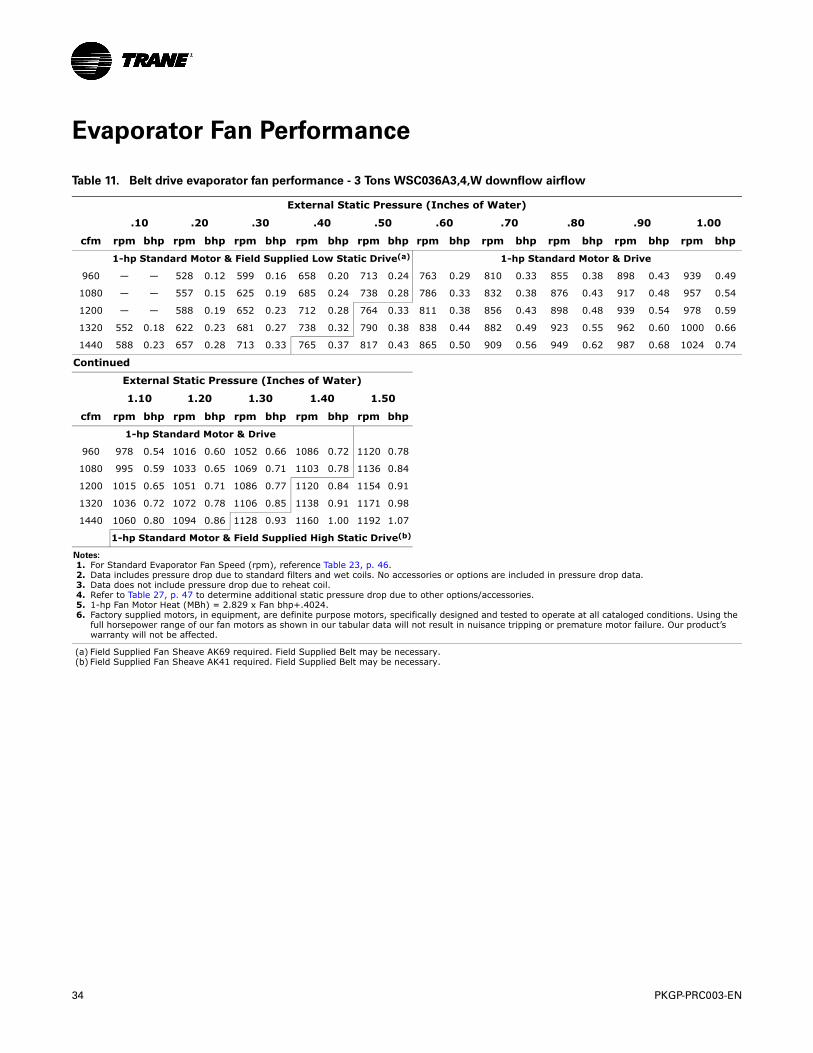
Evaporator Fan Performance
Table 11. Belt drive evaporator fan performance - 3 Tons WSC036A3,4,W downflow airflow
External Static Pressure (Inches of Water)
.10 .20 .30 .40 .50 .60 .70 .80 .90 1.00
cfm rpm bhp rpm bhp rpm bhp rpm bhp rpm bhp rpm bhp rpm bhp rpm bhp rpm bhp rpm bhp
1-hp Standard Motor & Field Supplied Low Static Drive(a) 1-hp Standard Motor & Drive
960 — — 528 0.12 599 0.16 658 0.20 713 0.24 763 0.29 810 0.33 855 0.38 898 0.43 939 0.49
1080 — — 557 0.15 625 0.19 685 0.24 738 0.28 786 0.33 832 0.38 876 0.43 917 0.48 957 0.54
1200 — — 588 0.19 652 0.23 712 0.28 764 0.33 811 0.38 856 0.43 898 0.48 939 0.54 978 0.59
1320 552 0.18 622 0.23 681 0.27 738 0.32 790 0.38 838 0.44 882 0.49 923 0.55 962 0.60 1000 0.66
1440 588 0.23 657 0.28 713 0.33 765 0.37 817 0.43 865 0.50 909 0.56 949 0.62 987 0.68 1024 0.74
Continued
External Static Pressure (Inches of Water)
1.10 1.20 1.30 1.40 1.50
cfm rpm bhp rpm bhp rpm bhp rpm bhp rpm bhp
1-hp Standard Motor & Drive
960 978 0.54 1016 0.60 1052 0.66 1086 0.72 1120 0.78
1080 995 0.59 1033 0.65 1069 0.71 1103 0.78 1136 0.84
1200 1015 0.65 1051 0.71 1086 0.77 1120 0.84 1154 0.91
1320 1036 0.72 1072 0.78 1106 0.85 1138 0.91 1171 0.98
1440 1060 0.80 1094 0.86 1128 0.93 1160 1.00 1192 1.07
1-hp Standard Motor & Field Supplied High Static Drive(b)
Notes:
1. For Standard Evaporator Fan Speed (rpm), reference Table 23, p. 46. 2. Data includes pressure drop due to standard filters and wet coils. No accessories or options are included in pressure drop data. 3. Data does not include pressure drop due to reheat coil. 4. Refer to Table 27, p. 47 to determine additional static pressure drop due to other options/accessories. 5. 1-hp Fan Motor Heat (MBh) = 2.829 x Fan bhp+.4024. 6. Factory supplied motors, in equipment, are definite purpose motors, specifically designed and tested to operate at all cataloged conditions. Using the
full horsepower range of our fan motors as shown in our tabular data will not result in nuisance tripping or premature motor failure. Our product’s warranty will not be affected.
(a) Field Supplied Fan Sheave AK69 required. Field Supplied Belt may be necessary.(b) Field Supplied Fan Sheave AK41 required. Field Supplied Belt may be necessary.
PKGP-PRC003-EN 35
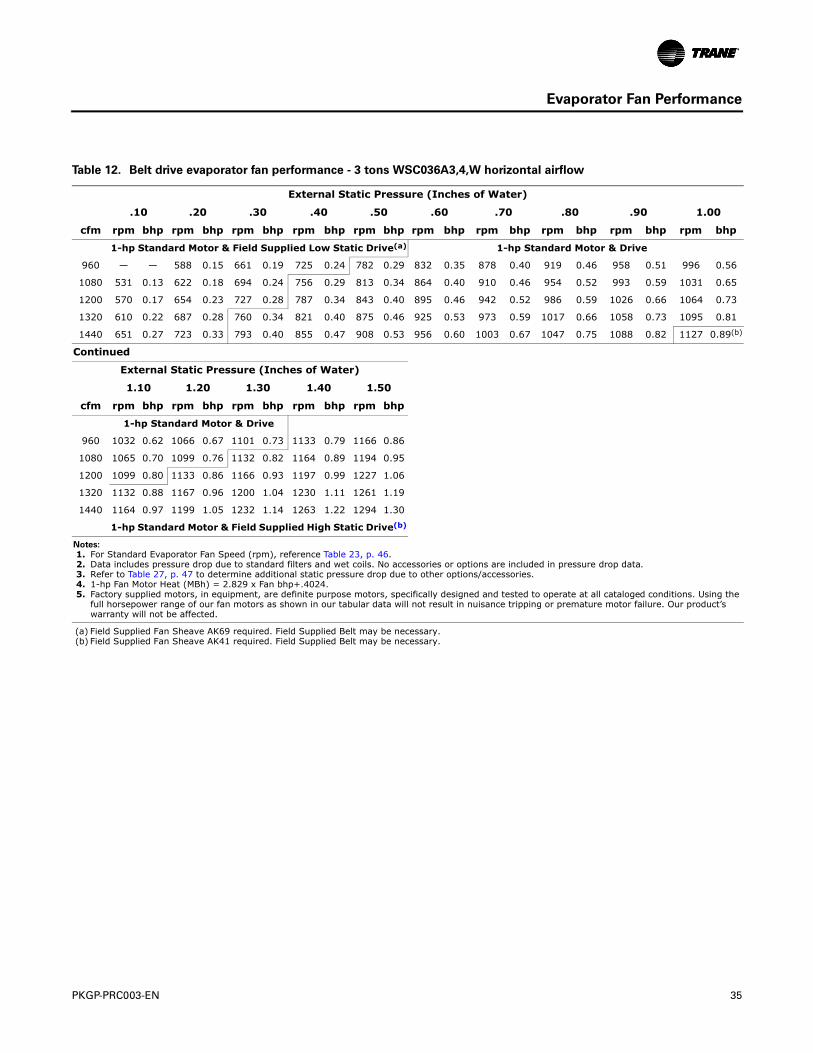
Evaporator Fan Performance
Table 12. Belt drive evaporator fan performance - 3 tons WSC036A3,4,W horizontal airflow
External Static Pressure (Inches of Water)
.10 .20 .30 .40 .50 .60 .70 .80 .90 1.00
cfm rpm bhp rpm bhp rpm bhp rpm bhp rpm bhp rpm bhp rpm bhp rpm bhp rpm bhp rpm bhp
1-hp Standard Motor & Field Supplied Low Static Drive(a) 1-hp Standard Motor & Drive
960 — — 588 0.15 661 0.19 725 0.24 782 0.29 832 0.35 878 0.40 919 0.46 958 0.51 996 0.56
1080 531 0.13 622 0.18 694 0.24 756 0.29 813 0.34 864 0.40 910 0.46 954 0.52 993 0.59 1031 0.65
1200 570 0.17 654 0.23 727 0.28 787 0.34 843 0.40 895 0.46 942 0.52 986 0.59 1026 0.66 1064 0.73
1320 610 0.22 687 0.28 760 0.34 821 0.40 875 0.46 925 0.53 973 0.59 1017 0.66 1058 0.73 1095 0.81
1440 651 0.27 723 0.33 793 0.40 855 0.47 908 0.53 956 0.60 1003 0.67 1047 0.75 1088 0.82 1127 0.89(b)
Continued
External Static Pressure (Inches of Water)
1.10 1.20 1.30 1.40 1.50
cfm rpm bhp rpm bhp rpm bhp rpm bhp rpm bhp
1-hp Standard Motor & Drive
960 1032 0.62 1066 0.67 1101 0.73 1133 0.79 1166 0.86
1080 1065 0.70 1099 0.76 1132 0.82 1164 0.89 1194 0.95
1200 1099 0.80 1133 0.86 1166 0.93 1197 0.99 1227 1.06
1320 1132 0.88 1167 0.96 1200 1.04 1230 1.11 1261 1.19
1440 1164 0.97 1199 1.05 1232 1.14 1263 1.22 1294 1.30
1-hp Standard Motor & Field Supplied High Static Drive(b)
Notes:
1. For Standard Evaporator Fan Speed (rpm), reference Table 23, p. 46. 2. Data includes pressure drop due to standard filters and wet coils. No accessories or options are included in pressure drop data. 3. Refer to Table 27, p. 47 to determine additional static pressure drop due to other options/accessories. 4. 1-hp Fan Motor Heat (MBh) = 2.829 x Fan bhp+.4024. 5. Factory supplied motors, in equipment, are definite purpose motors, specifically designed and tested to operate at all cataloged conditions. Using the
full horsepower range of our fan motors as shown in our tabular data will not result in nuisance tripping or premature motor failure. Our product’s warranty will not be affected.
(a) Field Supplied Fan Sheave AK69 required. Field Supplied Belt may be necessary.(b) Field Supplied Fan Sheave AK41 required. Field Supplied Belt may be necessary.
36 PKGP-PRC003-EN
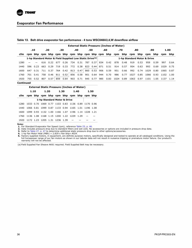
Evaporator Fan Performance
Table 13. Belt drive evaporator fan performance - 4 tons WSC048A3,4,W downflow airflow
External Static Pressure (Inches of Water)
.10 .20 .30 .40 .50 .60 .70 .80 .90 1.00
cfm rpm bhp rpm bhp rpm bhp rpm bhp rpm bhp rpm bhp rpm bhp rpm bhp rpm bhp rpm bhp
1-hp Standard Motor & Field Supplied Low Static Drive(a) 1-hp Standard Motor & Drive
1280 — — 616 0.22 677 0.26 734 0.31 787 0.37 834 0.42 878 0.48 919 0.53 959 0.59 997 0.64
1440 596 0.23 663 0.29 719 0.33 772 0.38 823 0.44 871 0.51 914 0.57 954 0.63 993 0.69 1029 0.75
1600 647 0.31 711 0.37 764 0.42 813 0.47 860 0.53 906 0.59 951 0.66 992 0.74 1029 0.80 1065 0.87
1760 701 0.41 758 0.46 811 0.52 856 0.58 901 0.64 944 0.70 986 0.77 1027 0.85 1066 0.93 1102 1.00
1920 755 0.52 807 0.57 859 0.64 903 0.71 945 0.77 985 0.83 1024 0.89 1063 0.97 1101 1.05 1137 1.14
Continued
External Static Pressure (Inches of Water)
1.10 1.20 1.30 1.40 1.50
cfm rpm bhp rpm bhp rpm bhp rpm bhp rpm bhp
1-hp Standard Motor & Drive
1280 1033 0.70 1069 0.77 1103 0.83 1136 0.89 1170 0.96
1440 1066 0.81 1099 0.87 1133 0.94 1165 1.01 1196 1.08
1600 1099 0.93 1132 1.00 1166 1.07 1196 1.14 1228 1.21
1760 1136 1.08 1168 1.15 1200 1.22 1229 1.29 — —
1920 1172 1.23 1205 1.31 1236 1.39 — — — —
Notes:
1. For Standard Evaporator Fan Speed (rpm), reference Table 23, p. 46. 2. Data includes pressure drop due to standard filters and wet coils. No accessories or options are included in pressure drop data. 3. Refer to Table 27, p. 47 to determine additional static pressure drop due to other options/accessories. 4. 1-hp Fan Motor Heat (MBh) = 2.829 x Fan bhp+.4024. 5. Factory supplied motors, in equipment, are definite purpose motors, specifically designed and tested to operate at all cataloged conditions. Using the
full horsepower range of our fan motors as shown in our tabular data will not result in nuisance tripping or premature motor failure. Our product’s warranty will not be affected.
(a) Field Supplied Fan Sheave AK61 required. Field Supplied Belt may be necessary.
PKGP-PRC003-EN 37
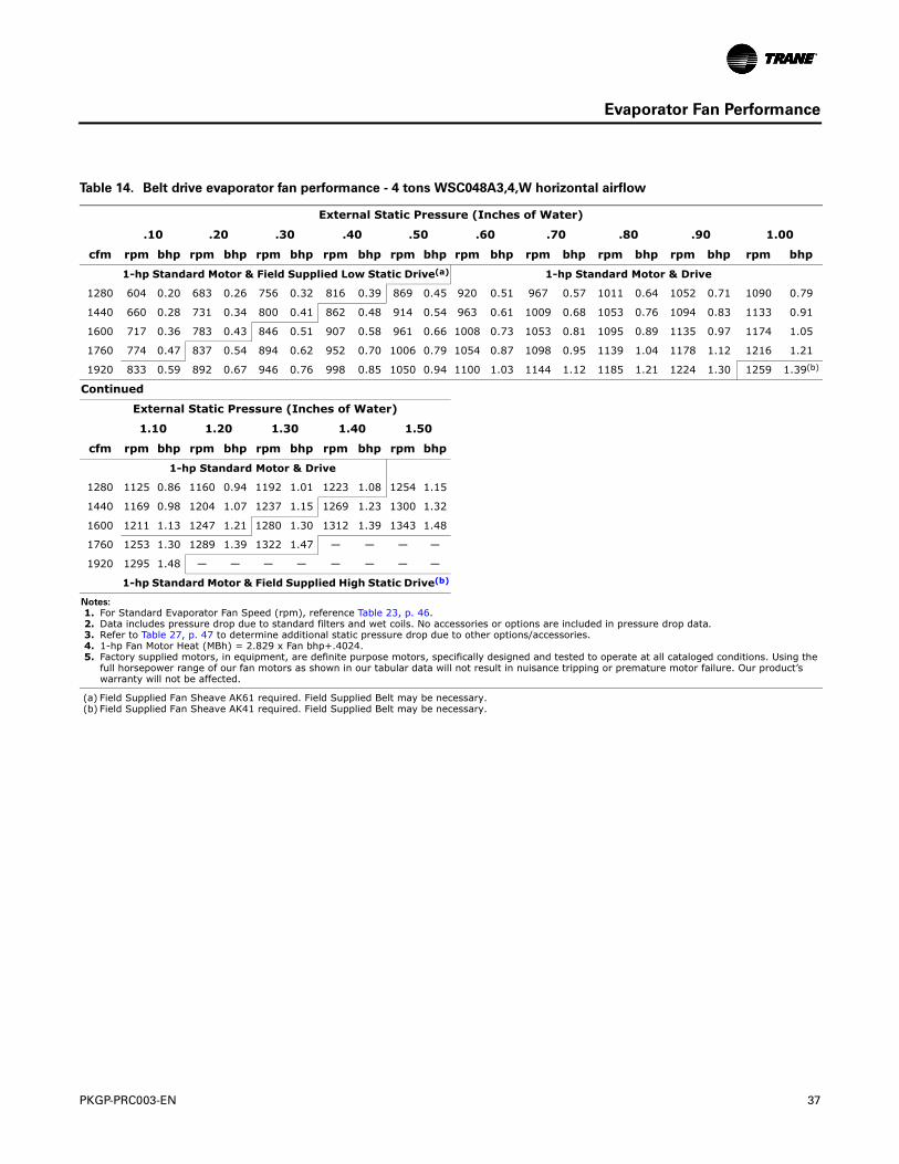
Evaporator Fan Performance
Table 14. Belt drive evaporator fan performance - 4 tons WSC048A3,4,W horizontal airflow
External Static Pressure (Inches of Water)
.10 .20 .30 .40 .50 .60 .70 .80 .90 1.00
cfm rpm bhp rpm bhp rpm bhp rpm bhp rpm bhp rpm bhp rpm bhp rpm bhp rpm bhp rpm bhp
1-hp Standard Motor & Field Supplied Low Static Drive(a) 1-hp Standard Motor & Drive
1280 604 0.20 683 0.26 756 0.32 816 0.39 869 0.45 920 0.51 967 0.57 1011 0.64 1052 0.71 1090 0.79
1440 660 0.28 731 0.34 800 0.41 862 0.48 914 0.54 963 0.61 1009 0.68 1053 0.76 1094 0.83 1133 0.91
1600 717 0.36 783 0.43 846 0.51 907 0.58 961 0.66 1008 0.73 1053 0.81 1095 0.89 1135 0.97 1174 1.05
1760 774 0.47 837 0.54 894 0.62 952 0.70 1006 0.79 1054 0.87 1098 0.95 1139 1.04 1178 1.12 1216 1.21
1920 833 0.59 892 0.67 946 0.76 998 0.85 1050 0.94 1100 1.03 1144 1.12 1185 1.21 1224 1.30 1259 1.39(b)
Continued
External Static Pressure (Inches of Water)
1.10 1.20 1.30 1.40 1.50
cfm rpm bhp rpm bhp rpm bhp rpm bhp rpm bhp
1-hp Standard Motor & Drive
1280 1125 0.86 1160 0.94 1192 1.01 1223 1.08 1254 1.15
1440 1169 0.98 1204 1.07 1237 1.15 1269 1.23 1300 1.32
1600 1211 1.13 1247 1.21 1280 1.30 1312 1.39 1343 1.48
1760 1253 1.30 1289 1.39 1322 1.47 — — — —
1920 1295 1.48 — — — — — — — —
1-hp Standard Motor & Field Supplied High Static Drive(b)
Notes:
1. For Standard Evaporator Fan Speed (rpm), reference Table 23, p. 46. 2. Data includes pressure drop due to standard filters and wet coils. No accessories or options are included in pressure drop data. 3. Refer to Table 27, p. 47 to determine additional static pressure drop due to other options/accessories. 4. 1-hp Fan Motor Heat (MBh) = 2.829 x Fan bhp+.4024. 5. Factory supplied motors, in equipment, are definite purpose motors, specifically designed and tested to operate at all cataloged conditions. Using the
full horsepower range of our fan motors as shown in our tabular data will not result in nuisance tripping or premature motor failure. Our product’s warranty will not be affected.
(a) Field Supplied Fan Sheave AK61 required. Field Supplied Belt may be necessary.(b) Field Supplied Fan Sheave AK41 required. Field Supplied Belt may be necessary.
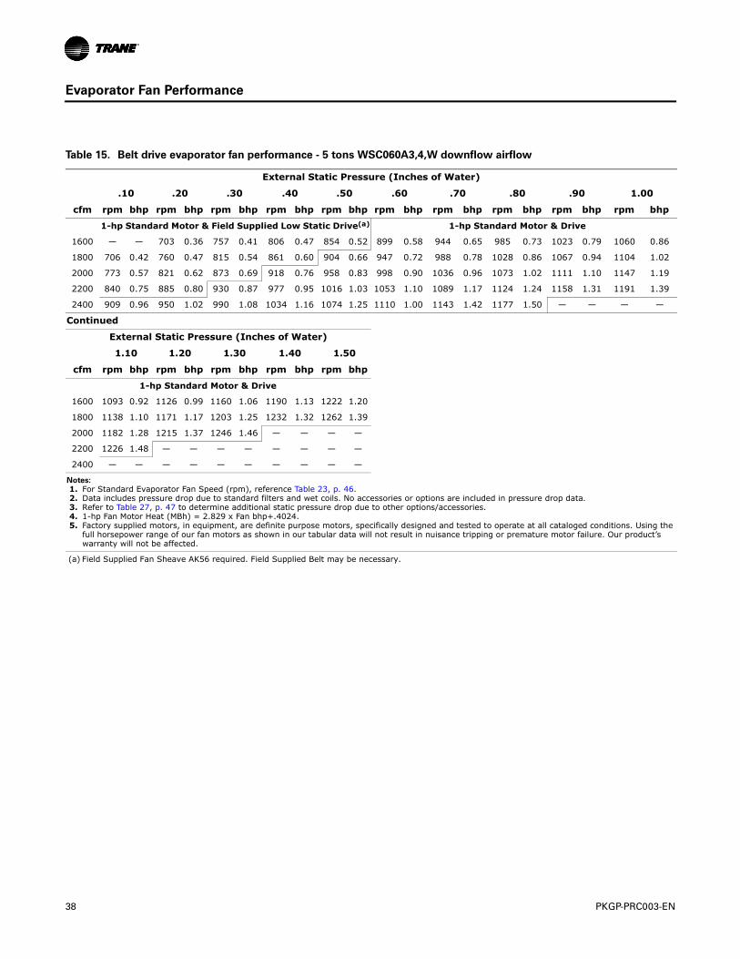
38 PKGP-PRC003-EN
Evaporator Fan Performance
Table 15. Belt drive evaporator fan performance - 5 tons WSC060A3,4,W downflow airflow
External Static Pressure (Inches of Water)
.10 .20 .30 .40 .50 .60 .70 .80 .90 1.00
cfm rpm bhp rpm bhp rpm bhp rpm bhp rpm bhp rpm bhp rpm bhp rpm bhp rpm bhp rpm bhp
1-hp Standard Motor & Field Supplied Low Static Drive(a) 1-hp Standard Motor & Drive
1600 — — 703 0.36 757 0.41 806 0.47 854 0.52 899 0.58 944 0.65 985 0.73 1023 0.79 1060 0.86
1800 706 0.42 760 0.47 815 0.54 861 0.60 904 0.66 947 0.72 988 0.78 1028 0.86 1067 0.94 1104 1.02
2000 773 0.57 821 0.62 873 0.69 918 0.76 958 0.83 998 0.90 1036 0.96 1073 1.02 1111 1.10 1147 1.19
2200 840 0.75 885 0.80 930 0.87 977 0.95 1016 1.03 1053 1.10 1089 1.17 1124 1.24 1158 1.31 1191 1.39
2400 909 0.96 950 1.02 990 1.08 1034 1.16 1074 1.25 1110 1.00 1143 1.42 1177 1.50 — — — —
Continued
External Static Pressure (Inches of Water)
1.10 1.20 1.30 1.40 1.50
cfm rpm bhp rpm bhp rpm bhp rpm bhp rpm bhp
1-hp Standard Motor & Drive
1600 1093 0.92 1126 0.99 1160 1.06 1190 1.13 1222 1.20
1800 1138 1.10 1171 1.17 1203 1.25 1232 1.32 1262 1.39
2000 1182 1.28 1215 1.37 1246 1.46 — — — —
2200 1226 1.48 — — — — — — — —
2400 — — — — — — — — — —
Notes:
1. For Standard Evaporator Fan Speed (rpm), reference Table 23, p. 46. 2. Data includes pressure drop due to standard filters and wet coils. No accessories or options are included in pressure drop data. 3. Refer to Table 27, p. 47 to determine additional static pressure drop due to other options/accessories. 4. 1-hp Fan Motor Heat (MBh) = 2.829 x Fan bhp+.4024. 5. Factory supplied motors, in equipment, are definite purpose motors, specifically designed and tested to operate at all cataloged conditions. Using the
full horsepower range of our fan motors as shown in our tabular data will not result in nuisance tripping or premature motor failure. Our product’s warranty will not be affected.
(a) Field Supplied Fan Sheave AK56 required. Field Supplied Belt may be necessary.
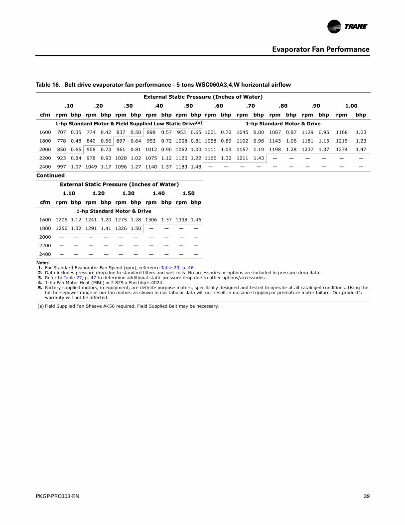
PKGP-PRC003-EN 39
Evaporator Fan Performance
Table 16. Belt drive evaporator fan performance - 5 tons WSC060A3,4,W horizontal airflow
External Static Pressure (Inches of Water)
.10 .20 .30 .40 .50 .60 .70 .80 .90 1.00
cfm rpm bhp rpm bhp rpm bhp rpm bhp rpm bhp rpm bhp rpm bhp rpm bhp rpm bhp rpm bhp
1-hp Standard Motor & Field Supplied Low Static Drive(a) 1-hp Standard Motor & Drive
1600 707 0.35 774 0.42 837 0.50 898 0.57 953 0.65 1001 0.72 1045 0.80 1087 0.87 1129 0.95 1168 1.03
1800 778 0.48 840 0.56 897 0.64 953 0.72 1008 0.81 1058 0.89 1102 0.98 1143 1.06 1181 1.15 1219 1.23
2000 850 0.65 908 0.73 961 0.81 1012 0.90 1062 1.00 1111 1.09 1157 1.19 1198 1.28 1237 1.37 1274 1.47
2200 923 0.84 978 0.93 1028 1.02 1075 1.12 1120 1.22 1166 1.32 1211 1.43 — — — — — —
2400 997 1.07 1049 1.17 1096 1.27 1140 1.37 1183 1.48 — — — — — — — — — —
Continued
External Static Pressure (Inches of Water)
1.10 1.20 1.30 1.40 1.50
cfm rpm bhp rpm bhp rpm bhp rpm bhp rpm bhp
1-hp Standard Motor & Drive
1600 1206 1.12 1241 1.20 1275 1.28 1306 1.37 1338 1.46
1800 1256 1.32 1291 1.41 1326 1.50 — — — —
2000 — — — — — — — — — —
2200 — — — — — — — — — —
2400 — — — — — — — — — —
Notes:
1. For Standard Evaporator Fan Speed (rpm), reference Table 23, p. 46. 2. Data includes pressure drop due to standard filters and wet coils. No accessories or options are included in pressure drop data. 3. Refer to Table 27, p. 47 to determine additional static pressure drop due to other options/accessories. 4. 1-hp Fan Motor Heat (MBh) = 2.829 x Fan bhp+.4024. 5. Factory supplied motors, in equipment, are definite purpose motors, specifically designed and tested to operate at all cataloged conditions. Using the
full horsepower range of our fan motors as shown in our tabular data will not result in nuisance tripping or premature motor failure. Our product’s warranty will not be affected.
(a) Field Supplied Fan Sheave AK56 required. Field Supplied Belt may be necessary.
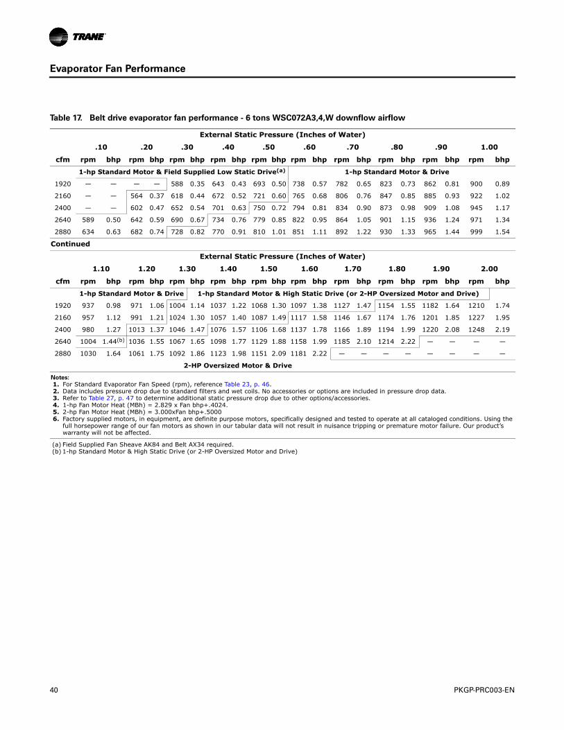
40 PKGP-PRC003-EN
Evaporator Fan Performance
Table 17. Belt drive evaporator fan performance - 6 tons WSC072A3,4,W downflow airflow
External Static Pressure (Inches of Water)
.10 .20 .30 .40 .50 .60 .70 .80 .90 1.00
cfm rpm bhp rpm bhp rpm bhp rpm bhp rpm bhp rpm bhp rpm bhp rpm bhp rpm bhp rpm bhp
1-hp Standard Motor & Field Supplied Low Static Drive(a) 1-hp Standard Motor & Drive
1920 — — — — 588 0.35 643 0.43 693 0.50 738 0.57 782 0.65 823 0.73 862 0.81 900 0.89
2160 — — 564 0.37 618 0.44 672 0.52 721 0.60 765 0.68 806 0.76 847 0.85 885 0.93 922 1.02
2400 — — 602 0.47 652 0.54 701 0.63 750 0.72 794 0.81 834 0.90 873 0.98 909 1.08 945 1.17
2640 589 0.50 642 0.59 690 0.67 734 0.76 779 0.85 822 0.95 864 1.05 901 1.15 936 1.24 971 1.34
2880 634 0.63 682 0.74 728 0.82 770 0.91 810 1.01 851 1.11 892 1.22 930 1.33 965 1.44 999 1.54
Continued
External Static Pressure (Inches of Water)
1.10 1.20 1.30 1.40 1.50 1.60 1.70 1.80 1.90 2.00
cfm rpm bhp rpm bhp rpm bhp rpm bhp rpm bhp rpm bhp rpm bhp rpm bhp rpm bhp rpm bhp
1-hp Standard Motor & Drive 1-hp Standard Motor & High Static Drive (or 2-HP Oversized Motor and Drive)
1920 937 0.98 971 1.06 1004 1.14 1037 1.22 1068 1.30 1097 1.38 1127 1.47 1154 1.55 1182 1.64 1210 1.74
2160 957 1.12 991 1.21 1024 1.30 1057 1.40 1087 1.49 1117 1.58 1146 1.67 1174 1.76 1201 1.85 1227 1.95
2400 980 1.27 1013 1.37 1046 1.47 1076 1.57 1106 1.68 1137 1.78 1166 1.89 1194 1.99 1220 2.08 1248 2.19
2640 1004 1.44(b) 1036 1.55 1067 1.65 1098 1.77 1129 1.88 1158 1.99 1185 2.10 1214 2.22 — — — —
2880 1030 1.64 1061 1.75 1092 1.86 1123 1.98 1151 2.09 1181 2.22 — — — — — — — —
2-HP Oversized Motor & Drive
Notes:
1. For Standard Evaporator Fan Speed (rpm), reference Table 23, p. 46. 2. Data includes pressure drop due to standard filters and wet coils. No accessories or options are included in pressure drop data. 3. Refer to Table 27, p. 47 to determine additional static pressure drop due to other options/accessories. 4. 1-hp Fan Motor Heat (MBh) = 2.829 x Fan bhp+.4024. 5. 2-hp Fan Motor Heat (MBh) = 3.000xFan bhp+.5000 6. Factory supplied motors, in equipment, are definite purpose motors, specifically designed and tested to operate at all cataloged conditions. Using the
full horsepower range of our fan motors as shown in our tabular data will not result in nuisance tripping or premature motor failure. Our product’s warranty will not be affected.
(a) Field Supplied Fan Sheave AK84 and Belt AX34 required.(b) 1-hp Standard Motor & High Static Drive (or 2-HP Oversized Motor and Drive)
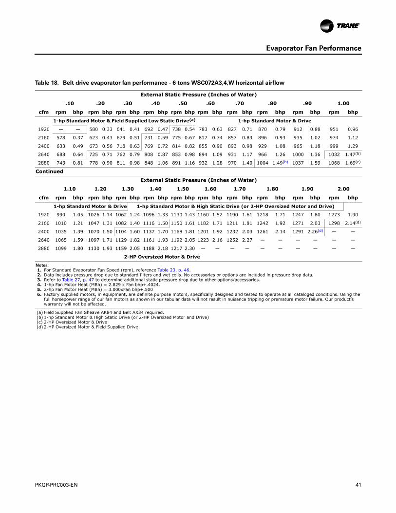
PKGP-PRC003-EN 41
Evaporator Fan Performance
Table 18. Belt drive evaporator fan performance - 6 tons WSC072A3,4,W horizontal airflow
External Static Pressure (Inches of Water)
.10 .20 .30 .40 .50 .60 .70 .80 .90 1.00
cfm rpm bhp rpm bhp rpm bhp rpm bhp rpm bhp rpm bhp rpm bhp rpm bhp rpm bhp rpm bhp
1-hp Standard Motor & Field Supplied Low Static Drive(a) 1-hp Standard Motor & Drive
1920 — — 580 0.33 641 0.41 692 0.47 738 0.54 783 0.63 827 0.71 870 0.79 912 0.88 951 0.96
2160 578 0.37 623 0.43 679 0.51 731 0.59 775 0.67 817 0.74 857 0.83 896 0.93 935 1.02 974 1.12
2400 633 0.49 673 0.56 718 0.63 769 0.72 814 0.82 855 0.90 893 0.98 929 1.08 965 1.18 999 1.29
2640 688 0.64 725 0.71 762 0.79 808 0.87 853 0.98 894 1.09 931 1.17 966 1.26 1000 1.36 1032 1.47(b)
2880 743 0.81 778 0.90 811 0.98 848 1.06 891 1.16 932 1.28 970 1.40 1004 1.49(b) 1037 1.59 1068 1.69(c)
Continued
External Static Pressure (Inches of Water)
1.10 1.20 1.30 1.40 1.50 1.60 1.70 1.80 1.90 2.00
cfm rpm bhp rpm bhp rpm bhp rpm bhp rpm bhp rpm bhp rpm bhp rpm bhp rpm bhp rpm bhp
1-hp Standard Motor & Drive 1-hp Standard Motor & High Static Drive (or 2-HP Oversized Motor and Drive)
1920 990 1.05 1026 1.14 1062 1.24 1096 1.33 1130 1.43 1160 1.52 1190 1.61 1218 1.71 1247 1.80 1273 1.90
2160 1010 1.21 1047 1.31 1082 1.40 1116 1.50 1150 1.61 1182 1.71 1211 1.81 1242 1.92 1271 2.03 1298 2.14(d)
2400 1035 1.39 1070 1.50 1104 1.60 1137 1.70 1168 1.81 1201 1.92 1232 2.03 1261 2.14 1291 2.26(d) — —
2640 1065 1.59 1097 1.71 1129 1.82 1161 1.93 1192 2.05 1223 2.16 1252 2.27 — — — — — —
2880 1099 1.80 1130 1.93 1159 2.05 1188 2.18 1217 2.30 — — — — — — — — — —
2-HP Oversized Motor & Drive
Notes:
1. For Standard Evaporator Fan Speed (rpm), reference Table 23, p. 46. 2. Data includes pressure drop due to standard filters and wet coils. No accessories or options are included in pressure drop data. 3. Refer to Table 27, p. 47 to determine additional static pressure drop due to other options/accessories. 4. 1-hp Fan Motor Heat (MBh) = 2.829 x Fan bhp+.4024. 5. 2-hp Fan Motor Heat (MBh) = 3.000xFan bhp+.500 6. Factory supplied motors, in equipment, are definite purpose motors, specifically designed and tested to operate at all cataloged conditions. Using the
full horsepower range of our fan motors as shown in our tabular data will not result in nuisance tripping or premature motor failure. Our product’s warranty will not be affected.
(a) Field Supplied Fan Sheave AK84 and Belt AX34 required.(b) 1-hp Standard Motor & High Static Drive (or 2-HP Oversized Motor and Drive)(c) 2-HP Oversized Motor & Drive(d) 2-HP Oversized Motor & Field Supplied Drive
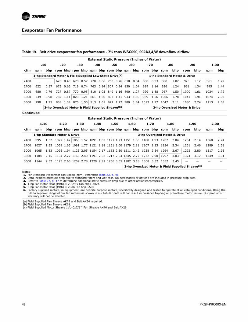
42 PKGP-PRC003-EN
Evaporator Fan Performance
Table 19. Belt drive evaporator fan performance - 7½ tons WSC090, 092A3,4,W downflow airflow
External Static Pressure (Inches of Water)
.10 .20 .30 .40 .50 .60 .70 .80 .90 1.00
cfm rpm bhp rpm bhp rpm bhp rpm bhp rpm bhp rpm bhp rpm bhp rpm bhp rpm bhp rpm bhp
1-hp Standard Motor & Field Supplied Low Static Drive(a) 1-hp Standard Motor & Drive
2400 — — 620 0.49 670 0.57 720 0.66 768 0.76 810 0.84 850 0.93 888 1.02 925 1.12 961 1.22
2700 622 0.57 673 0.66 719 0.74 763 0.84 807 0.94 850 1.04 889 1.14 926 1.24 961 1.34 995 1.44
3000 680 0.76 727 0.87 770 0.95 810 1.05 849 1.16 890 1.27 929 1.38 967 1.50 1000 1.61 1034 1.72
3300 739 0.98 782 1.11 823 1.21 861 1.30 897 1.41 933 1.50 969 1.66 1006 1.78 1041 1.91 1074 2.03
3600 798 1.25 838 1.39 876 1.50 913 1.61 947 1.72 980 1.84 1013 1.97 1047 2.11 1080 2.24 1113 2.38
3-hp Oversized Motor & Field Supplied Sheave(b) 3-hp Oversized Motor & Drive
Continued
External Static Pressure (Inches of Water)
1.10 1.20 1.30 1.40 1.50 1.60 1.70 1.80 1.90 2.00
cfm rpm bhp rpm bhp rpm bhp rpm bhp rpm bhp rpm bhp rpm bhp rpm bhp rpm bhp rpm bhp
1-hp Standard Motor & Drive 3-hp Oversized Motor & Drive
2400 995 1.32 1027 1.42 1060 1.52 1091 1.62 1121 1.73 1151 1.83 1180 1.93 1207 2.04 1234 2.14 1260 2.24
2700 1027 1.55 1059 1.65 1091 1.77 1121 1.88 1151 2.00 1179 2.11 1207 2.23 1234 2.34 1261 2.46 1289 2.58
3000 1065 1.83 1095 1.94 1125 2.05 1154 2.17 1183 2.30 1211 2.42 1238 2.54 1264 2.67 1292 2.80 1317 2.93
3300 1104 2.15 1134 2.27 1163 2.40 1191 2.52 1217 2.64 1245 2.77 1272 2.90 1297 3.03 1324 3.17 1349 3.31
3600 1144 2.52 1173 2.65 1202 2.78 1229 2.91 1256 3.05 1282 3.18 1308 3.32 1332 3.45 — — — —
3-hp Oversized Motor & Field Supplied Sheave(c)
Notes:
1. For Standard Evaporator Fan Speed (rpm), reference Table 23, p. 46. 2. Data includes pressure drop due to standard filters and wet coils. No accessories or options are included in pressure drop data. 3. Refer to Table 27, p. 47 to determine additional static pressure drop due to other options/accessories. 4. 1-hp Fan Motor Heat (MBh) = 2.829 x Fan bhp+.4024. 5. 3-hp Fan Motor Heat (MBh) = 2.90xFan bhp+.500 6. Factory supplied motors, in equipment, are definite purpose motors, specifically designed and tested to operate at all cataloged conditions. Using the
full horsepower range of our fan motors as shown in our tabular data will not result in nuisance tripping or premature motor failure. Our product’s warranty will not be affected.
(a) Field Supplied Fan Sheave AK79 and Belt AX34 required.(b) Field Supplied Fan Sheave AK61.(c) Field Supplied Motor Sheave 1VL40x7/8”, Fan Sheave AK46 and Belt AX28.
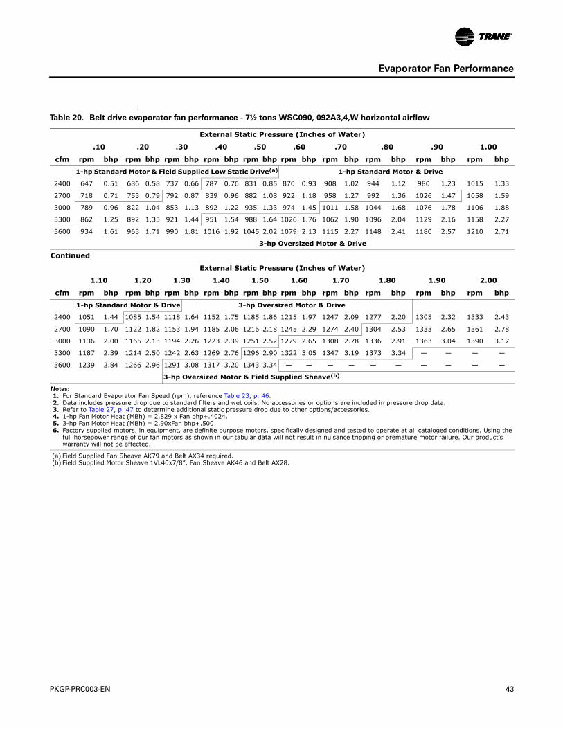
PKGP-PRC003-EN 43
Evaporator Fan Performance
a
Table 20. Belt drive evaporator fan performance - 7½ tons WSC090, 092A3,4,W horizontal airflow
External Static Pressure (Inches of Water)
.10 .20 .30 .40 .50 .60 .70 .80 .90 1.00
cfm rpm bhp rpm bhp rpm bhp rpm bhp rpm bhp rpm bhp rpm bhp rpm bhp rpm bhp rpm bhp
1-hp Standard Motor & Field Supplied Low Static Drive(a) 1-hp Standard Motor & Drive
2400 647 0.51 686 0.58 737 0.66 787 0.76 831 0.85 870 0.93 908 1.02 944 1.12 980 1.23 1015 1.33
2700 718 0.71 753 0.79 792 0.87 839 0.96 882 1.08 922 1.18 958 1.27 992 1.36 1026 1.47 1058 1.59
3000 789 0.96 822 1.04 853 1.13 892 1.22 935 1.33 974 1.45 1011 1.58 1044 1.68 1076 1.78 1106 1.88
3300 862 1.25 892 1.35 921 1.44 951 1.54 988 1.64 1026 1.76 1062 1.90 1096 2.04 1129 2.16 1158 2.27
3600 934 1.61 963 1.71 990 1.81 1016 1.92 1045 2.02 1079 2.13 1115 2.27 1148 2.41 1180 2.57 1210 2.71
3-hp Oversized Motor & Drive
Continued
External Static Pressure (Inches of Water)
1.10 1.20 1.30 1.40 1.50 1.60 1.70 1.80 1.90 2.00
cfm rpm bhp rpm bhp rpm bhp rpm bhp rpm bhp rpm bhp rpm bhp rpm bhp rpm bhp rpm bhp
1-hp Standard Motor & Drive 3-hp Oversized Motor & Drive
2400 1051 1.44 1085 1.54 1118 1.64 1152 1.75 1185 1.86 1215 1.97 1247 2.09 1277 2.20 1305 2.32 1333 2.43
2700 1090 1.70 1122 1.82 1153 1.94 1185 2.06 1216 2.18 1245 2.29 1274 2.40 1304 2.53 1333 2.65 1361 2.78
3000 1136 2.00 1165 2.13 1194 2.26 1223 2.39 1251 2.52 1279 2.65 1308 2.78 1336 2.91 1363 3.04 1390 3.17
3300 1187 2.39 1214 2.50 1242 2.63 1269 2.76 1296 2.90 1322 3.05 1347 3.19 1373 3.34 — — — —
3600 1239 2.84 1266 2.96 1291 3.08 1317 3.20 1343 3.34 — — — — — — — — — —
3-hp Oversized Motor & Field Supplied Sheave(b)
Notes:
1. For Standard Evaporator Fan Speed (rpm), reference Table 23, p. 46. 2. Data includes pressure drop due to standard filters and wet coils. No accessories or options are included in pressure drop data. 3. Refer to Table 27, p. 47 to determine additional static pressure drop due to other options/accessories. 4. 1-hp Fan Motor Heat (MBh) = 2.829 x Fan bhp+.4024. 5. 3-hp Fan Motor Heat (MBh) = 2.90xFan bhp+.500 6. Factory supplied motors, in equipment, are definite purpose motors, specifically designed and tested to operate at all cataloged conditions. Using the
full horsepower range of our fan motors as shown in our tabular data will not result in nuisance tripping or premature motor failure. Our product’s warranty will not be affected.
(a) Field Supplied Fan Sheave AK79 and Belt AX34 required.(b) Field Supplied Motor Sheave 1VL40x7/8”, Fan Sheave AK46 and Belt AX28.
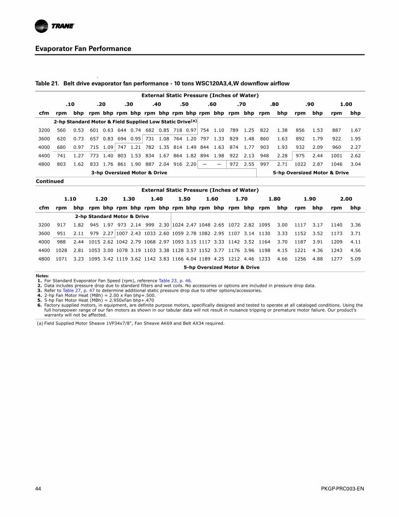
44 PKGP-PRC003-EN
Evaporator Fan Performance
a
Table 21. Belt drive evaporator fan performance - 10 tons WSC120A3,4,W downflow airflow
External Static Pressure (Inches of Water)
.10 .20 .30 .40 .50 .60 .70 .80 .90 1.00
cfm rpm bhp rpm bhp rpm bhp rpm bhp rpm bhp rpm bhp rpm bhp rpm bhp rpm bhp rpm bhp
2-hp Standard Motor & Field Supplied Low Static Drive(a)
3200 560 0.53 601 0.63 644 0.74 682 0.85 718 0.97 754 1.10 789 1.25 822 1.38 856 1.53 887 1.67
3600 620 0.73 657 0.83 694 0.95 731 1.08 764 1.20 797 1.33 829 1.48 860 1.63 892 1.79 922 1.95
4000 680 0.97 715 1.09 747 1.21 782 1.35 814 1.49 844 1.63 874 1.77 903 1.93 932 2.09 960 2.27
4400 741 1.27 773 1.40 803 1.53 834 1.67 864 1.82 894 1.98 922 2.13 948 2.28 975 2.44 1001 2.62
4800 803 1.62 833 1.76 861 1.90 887 2.04 916 2.20 — — 972 2.55 997 2.71 1022 2.87 1046 3.04
3-hp Oversized Motor & Drive 5-hp Oversized Motor & Drive
Continued
External Static Pressure (Inches of Water)
1.10 1.20 1.30 1.40 1.50 1.60 1.70 1.80 1.90 2.00
cfm rpm bhp rpm bhp rpm bhp rpm bhp rpm bhp rpm bhp rpm bhp rpm bhp rpm bhp rpm bhp
2-hp Standard Motor & Drive
3200 917 1.82 945 1.97 973 2.14 999 2.30 1024 2.47 1048 2.65 1072 2.82 1095 3.00 1117 3.17 1140 3.36
3600 951 2.11 979 2.27 1007 2.43 1033 2.60 1059 2.78 1082 2.95 1107 3.14 1130 3.33 1152 3.52 1173 3.71
4000 988 2.44 1015 2.62 1042 2.79 1068 2.97 1093 3.15 1117 3.33 1142 3.52 1164 3.70 1187 3.91 1209 4.11
4400 1028 2.81 1053 3.00 1078 3.19 1103 3.38 1128 3.57 1152 3.77 1176 3.96 1198 4.15 1221 4.36 1243 4.56
4800 1071 3.23 1095 3.42 1119 3.62 1142 3.83 1166 4.04 1189 4.25 1212 4.46 1233 4.66 1256 4.88 1277 5.09
5-hp Oversized Motor & Drive
Notes:
1. For Standard Evaporator Fan Speed (rpm), reference Table 23, p. 46. 2. Data includes pressure drop due to standard filters and wet coils. No accessories or options are included in pressure drop data. 3. Refer to Table 27, p. 47 to determine additional static pressure drop due to other options/accessories. 4. 2-hp Fan Motor Heat (MBh) = 2.00 x Fan bhp+.500. 5. 5-hp Fan Motor Heat (MBh) = 2.950xFan bhp+.470 6. Factory supplied motors, in equipment, are definite purpose motors, specifically designed and tested to operate at all cataloged conditions. Using the
full horsepower range of our fan motors as shown in our tabular data will not result in nuisance tripping or premature motor failure. Our product’s warranty will not be affected.
(a) Field Supplied Motor Sheave 1VP34x7/8”, Fan Sheave AK69 and Belt AX34 required.
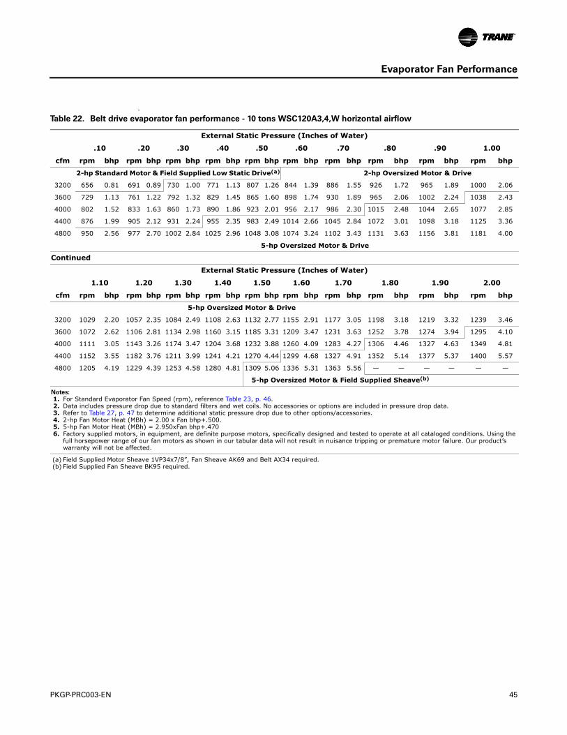
PKGP-PRC003-EN 45
Evaporator Fan Performance
a
Table 22. Belt drive evaporator fan performance - 10 tons WSC120A3,4,W horizontal airflow
External Static Pressure (Inches of Water)
.10 .20 .30 .40 .50 .60 .70 .80 .90 1.00
cfm rpm bhp rpm bhp rpm bhp rpm bhp rpm bhp rpm bhp rpm bhp rpm bhp rpm bhp rpm bhp
2-hp Standard Motor & Field Supplied Low Static Drive(a) 2-hp Oversized Motor & Drive
3200 656 0.81 691 0.89 730 1.00 771 1.13 807 1.26 844 1.39 886 1.55 926 1.72 965 1.89 1000 2.06
3600 729 1.13 761 1.22 792 1.32 829 1.45 865 1.60 898 1.74 930 1.89 965 2.06 1002 2.24 1038 2.43
4000 802 1.52 833 1.63 860 1.73 890 1.86 923 2.01 956 2.17 986 2.30 1015 2.48 1044 2.65 1077 2.85
4400 876 1.99 905 2.12 931 2.24 955 2.35 983 2.49 1014 2.66 1045 2.84 1072 3.01 1098 3.18 1125 3.36
4800 950 2.56 977 2.70 1002 2.84 1025 2.96 1048 3.08 1074 3.24 1102 3.43 1131 3.63 1156 3.81 1181 4.00
5-hp Oversized Motor & Drive
Continued
External Static Pressure (Inches of Water)
1.10 1.20 1.30 1.40 1.50 1.60 1.70 1.80 1.90 2.00
cfm rpm bhp rpm bhp rpm bhp rpm bhp rpm bhp rpm bhp rpm bhp rpm bhp rpm bhp rpm bhp
5-hp Oversized Motor & Drive
3200 1029 2.20 1057 2.35 1084 2.49 1108 2.63 1132 2.77 1155 2.91 1177 3.05 1198 3.18 1219 3.32 1239 3.46
3600 1072 2.62 1106 2.81 1134 2.98 1160 3.15 1185 3.31 1209 3.47 1231 3.63 1252 3.78 1274 3.94 1295 4.10
4000 1111 3.05 1143 3.26 1174 3.47 1204 3.68 1232 3.88 1260 4.09 1283 4.27 1306 4.46 1327 4.63 1349 4.81
4400 1152 3.55 1182 3.76 1211 3.99 1241 4.21 1270 4.44 1299 4.68 1327 4.91 1352 5.14 1377 5.37 1400 5.57
4800 1205 4.19 1229 4.39 1253 4.58 1280 4.81 1309 5.06 1336 5.31 1363 5.56 — — — — — —
5-hp Oversized Motor & Field Supplied Sheave(b)
Notes:
1. For Standard Evaporator Fan Speed (rpm), reference Table 23, p. 46. 2. Data includes pressure drop due to standard filters and wet coils. No accessories or options are included in pressure drop data. 3. Refer to Table 27, p. 47 to determine additional static pressure drop due to other options/accessories. 4. 2-hp Fan Motor Heat (MBh) = 2.00 x Fan bhp+.500. 5. 5-hp Fan Motor Heat (MBh) = 2.950xFan bhp+.470 6. Factory supplied motors, in equipment, are definite purpose motors, specifically designed and tested to operate at all cataloged conditions. Using the
full horsepower range of our fan motors as shown in our tabular data will not result in nuisance tripping or premature motor failure. Our product’s warranty will not be affected.
(a) Field Supplied Motor Sheave 1VP34x7/8”, Fan Sheave AK69 and Belt AX34 required.(b) Field Supplied Fan Sheave BK95 required.
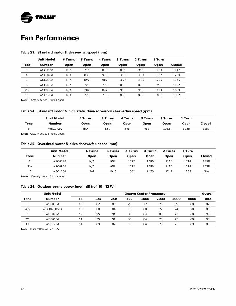
46 PKGP-PRC003-EN
Fan Performance
Table 23. Standard motor & sheave/fan speed (rpm)
Unit Model 6 Turns 5 Turns 4 Turns 3 Turns 2 Turns 1 Turn
Tons Number Open Open Open Open Open Open Closed
3 WSC036A N/A 745 819 894 968 1043 1117
4 WSC048A N/A 833 916 1000 1083 1167 1250
5 WSC060A N/A 897 987 1077 1166 1256 1346
6 WSC072A N/A 723 779 835 890 946 1002
7½ WSC090A N/A 787 847 908 968 1029 1089
10 WSC120A N/A 723 779 835 890 946 1002
Note: Factory set at 3 turns open.
Table 24. Standard motor & high static drive accessory sheave/fan speed (rpm)
Unit Model 6 Turns 5 Turns 4 Turns 3 Turns 2 Turns 1 Turn
Tons Number Open Open Open Open Open Open Closed
6 WSC072A N/A 831 895 959 1022 1086 1150
Note: Factory set at 3 turns open.
Table 25. Oversized motor & drive sheave/fan speed (rpm)
Unit Model 6 Turns 5 Turns 4 Turns 3 Turns 2 Turns 1 Turn
Tons Number Open Open Open Open Open Open Closed
6 WSC072A N/A 958 1022 1086 1150 1214 1278
7½ WSC090A N/A 958 1022 1086 1150 1214 1278
10 WSC120A 947 1015 1082 1150 1217 1285 N/A
Notes: Factory set at 3 turns open.
Table 26. Outdoor sound power level - dB (ref. 10 - 12 W)
Unit Model Octave Center Frequency Overall
Tons Number 63 125 250 500 1000 2000 4000 8000 dBA
3 WSC036A 85 82 80 79 77 73 69 68 82
4,5 WSC048,060A 95 88 84 83 80 77 74 70 85
6 WSC072A 92 95 91 88 84 80 75 68 90
7½ WSC090A 91 95 91 88 84 79 75 68 90
10 WSC120A 94 89 87 85 84 78 75 69 88
Note: Tests follow ARI270-95.
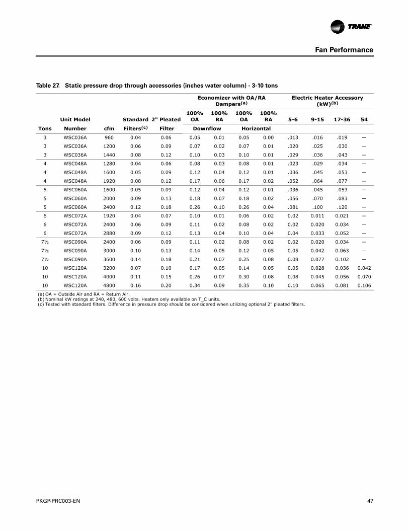
PKGP-PRC003-EN 47
Fan Performance
Table 27. Static pressure drop through accessories (inches water column) - 3-10 tons
Economizer with OA/RA Dampers(a)
Electric Heater Accessory (kW)(b)
Unit Model Standard 2" Pleated100%
OA100%
RA100%
OA100%
RA 5-6 9-15 17-36 54
Tons Number cfm Filters(c) Filter Downflow Horizontal
3 WSC036A 960 0.04 0.06 0.05 0.01 0.05 0.00 .013 .016 .019 —
3 WSC036A 1200 0.06 0.09 0.07 0.02 0.07 0.01 .020 .025 .030 —
3 WSC036A 1440 0.08 0.12 0.10 0.03 0.10 0.01 .029 .036 .043 —
4 WSC048A 1280 0.04 0.06 0.08 0.03 0.08 0.01 .023 .029 .034 —
4 WSC048A 1600 0.05 0.09 0.12 0.04 0.12 0.01 .036 .045 .053 —
4 WSC048A 1920 0.08 0.12 0.17 0.06 0.17 0.02 .052 .064 .077 —
5 WSC060A 1600 0.05 0.09 0.12 0.04 0.12 0.01 .036 .045 .053 —
5 WSC060A 2000 0.09 0.13 0.18 0.07 0.18 0.02 .056 .070 .083 —
5 WSC060A 2400 0.12 0.18 0.26 0.10 0.26 0.04 .081 .100 .120 —
6 WSC072A 1920 0.04 0.07 0.10 0.01 0.06 0.02 0.02 0.011 0.021 —
6 WSC072A 2400 0.06 0.09 0.11 0.02 0.08 0.02 0.02 0.020 0.034 —
6 WSC072A 2880 0.09 0.12 0.13 0.04 0.10 0.04 0.04 0.033 0.052 —
7½ WSC090A 2400 0.06 0.09 0.11 0.02 0.08 0.02 0.02 0.020 0.034 —
7½ WSC090A 3000 0.10 0.13 0.14 0.05 0.12 0.05 0.05 0.042 0.063 —
7½ WSC090A 3600 0.14 0.18 0.21 0.07 0.25 0.08 0.08 0.077 0.102 —
10 WSC120A 3200 0.07 0.10 0.17 0.05 0.14 0.05 0.05 0.028 0.036 0.042
10 WSC120A 4000 0.11 0.15 0.26 0.07 0.30 0.08 0.08 0.045 0.056 0.070
10 WSC120A 4800 0.16 0.20 0.34 0.09 0.35 0.10 0.10 0.065 0.081 0.106
(a) OA = Outside Air and RA = Return Air.(b) Nominal kW ratings at 240, 480, 600 volts. Heaters only available on T_C units.(c) Tested with standard filters. Difference in pressure drop should be considered when utilizing optional 2” pleated filters.
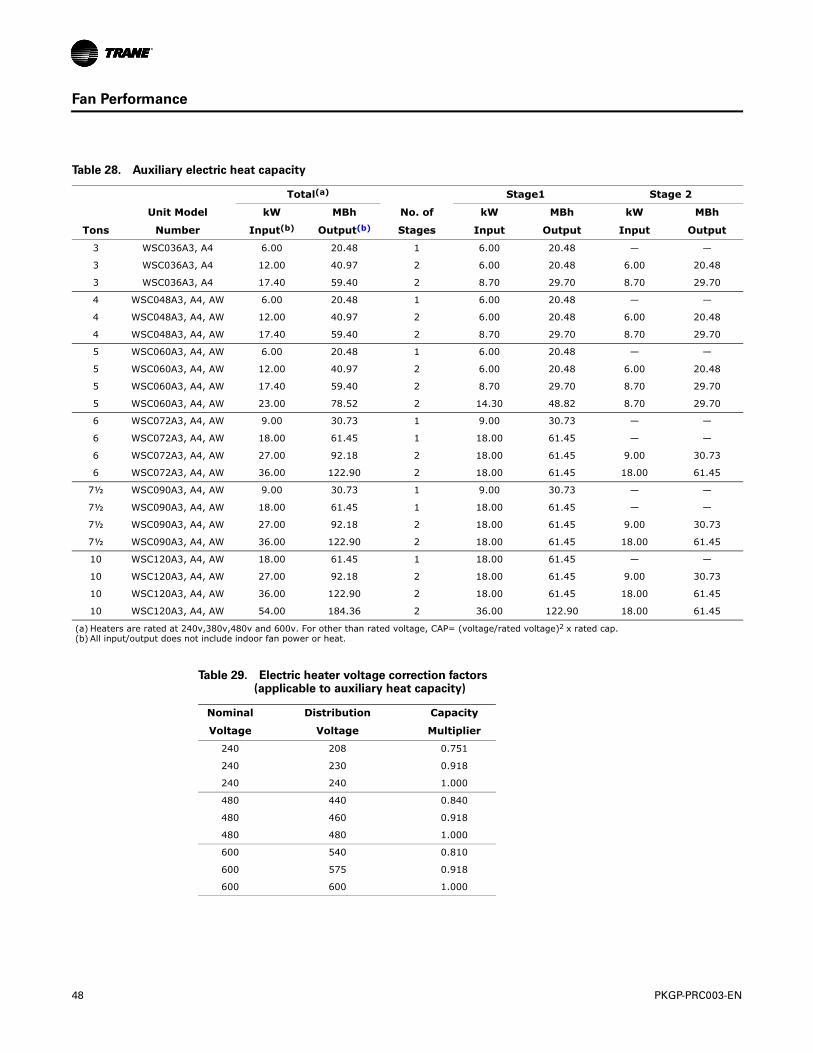
48 PKGP-PRC003-EN
Fan Performance
Table 28. Auxiliary electric heat capacity
Total(a) Stage1 Stage 2
Unit Model kW MBh No. of kW MBh kW MBh
Tons Number Input(b) Output(b) Stages Input Output Input Output
3 WSC036A3, A4 6.00 20.48 1 6.00 20.48 — —
3 WSC036A3, A4 12.00 40.97 2 6.00 20.48 6.00 20.48
3 WSC036A3, A4 17.40 59.40 2 8.70 29.70 8.70 29.70
4 WSC048A3, A4, AW 6.00 20.48 1 6.00 20.48 — —
4 WSC048A3, A4, AW 12.00 40.97 2 6.00 20.48 6.00 20.48
4 WSC048A3, A4, AW 17.40 59.40 2 8.70 29.70 8.70 29.70
5 WSC060A3, A4, AW 6.00 20.48 1 6.00 20.48 — —
5 WSC060A3, A4, AW 12.00 40.97 2 6.00 20.48 6.00 20.48
5 WSC060A3, A4, AW 17.40 59.40 2 8.70 29.70 8.70 29.70
5 WSC060A3, A4, AW 23.00 78.52 2 14.30 48.82 8.70 29.70
6 WSC072A3, A4, AW 9.00 30.73 1 9.00 30.73 — —
6 WSC072A3, A4, AW 18.00 61.45 1 18.00 61.45 — —
6 WSC072A3, A4, AW 27.00 92.18 2 18.00 61.45 9.00 30.73
6 WSC072A3, A4, AW 36.00 122.90 2 18.00 61.45 18.00 61.45
7½ WSC090A3, A4, AW 9.00 30.73 1 9.00 30.73 — —
7½ WSC090A3, A4, AW 18.00 61.45 1 18.00 61.45 — —
7½ WSC090A3, A4, AW 27.00 92.18 2 18.00 61.45 9.00 30.73
7½ WSC090A3, A4, AW 36.00 122.90 2 18.00 61.45 18.00 61.45
10 WSC120A3, A4, AW 18.00 61.45 1 18.00 61.45 — —
10 WSC120A3, A4, AW 27.00 92.18 2 18.00 61.45 9.00 30.73
10 WSC120A3, A4, AW 36.00 122.90 2 18.00 61.45 18.00 61.45
10 WSC120A3, A4, AW 54.00 184.36 2 36.00 122.90 18.00 61.45
(a) Heaters are rated at 240v,380v,480v and 600v. For other than rated voltage, CAP= (voltage/rated voltage)2 x rated cap.(b) All input/output does not include indoor fan power or heat.
Table 29. Electric heater voltage correction factors (applicable to auxiliary heat capacity)
Nominal Distribution Capacity
Voltage Voltage Multiplier
240 208 0.751
240 230 0.918
240 240 1.000
480 440 0.840
480 460 0.918
480 480 1.000
600 540 0.810
600 575 0.918
600 600 1.000
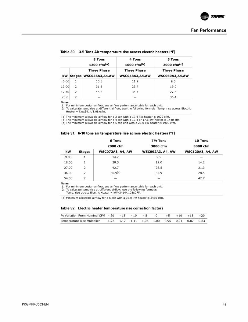
PKGP-PRC003-EN 49
Fan Performance
Table 30. 3-5 Tons Air temperature rise across electric heaters (°F)
3 Tons 4 Tons 5 Tons
1200 cfm(a)
(a) The minimum allowable airflow for a 3 ton with a 17.4 kW heater is 1020 cfm.
1600 cfm(b)
(b) The minimum allowable airflow for a 4 ton with a 17.4 or 17.6 kW heater is 1440 cfm.
2000 cfm(c)
(c) The minimum allowable airflow for a 5 ton unit with a 23.0 kW heater is 1900 cfm.
Three Phase Three Phase Three Phase
kW Stages WSC036A3,A4,AW WSC048A3,A4,AW WSC060A3,A4,AW
6.00 1 15.8 11.9 9.5
12.00 2 31.6 23.7 19.0
17.40 2 45.8 34.4 27.5
23.0 2 — — 36.4
Notes:
1. For minimum design airflow, see airflow performance table for each unit. 2. To calculate temp rise at different airflow, use the following formula: Temp. rise across Electric
Heater = kWx3414/1.08xcfm.
Table 31. 6-10 tons air temperature rise across electric heaters (°F)
6 Tons 7½ Tons 10 Tons
2000 cfm 3000 cfm 3000 cfm
kW Stages WSC072A3, A4, AW WSC092A3, A4, AW WSC120A3, A4, AW
9.00 1 14.2 9.5 —
18.00 1 28.5 19.0 14.2
27.00 2 42.7 28.5 21.3
36.00 2 56.9(a)
(a) Minimum allowable airflow for a 6 ton with a 36.0 kW heater is 2450 cfm.
37.9 28.5
54.00 2 — — 42.7
Notes:
1. For minimum design airflow, see airflow performance table for each unit. 2. To calculate temp rise at different airflow, use the following formula:
Temp. rise across Electric Heater = kWx3414/1.08xCFM.
Table 32. Electric heater temperature rise correction factors
% Variation From Nominal CFM - 20 - 15 - 10 - 5 0 +5 +10 +15 +20
Temperature Rise Multiplier 1.25 1.17 1.11 1.05 1.00 0.95 0.91 0.87 0.83
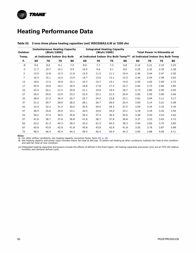
50 PKGP-PRC003-EN
Heating Performance Data
Table 33. 3 tons three phase heating capacities (net) WSC036A3,4,W at 1200 cfm
OutdoorInstantaneous Heating Capacity
(Btuh/1000)Integrated Heating Capacity
(Btuh/1000) Total Power in Kilowatts at
Temp. at Indicated Indoor Dry Bulb at Indicated Indoor Dry Bulb Temp(a) at Indicated Indoor Dry Bulb Temp
F. 60 70 75 80 60 70 75 80 60 70 75 80
-8 9.6 8.6 8.1 7.5 8.6 7.7 7.3 6.8 2.14 2.21 2.23 2.25
-3 11.7 10.7 10.1 9.5 10.5 9.6 9.1 8.6 2.25 2.32 2.35 2.38
2 13.9 12.8 12.3 11.6 12.5 11.5 11.1 10.4 2.36 2.44 2.47 2.50
7 16.3 15.1 14.5 13.9 14.7 13.6 13.1 12.5 2.46 2.54 2.58 2.62
12 18.6 17.4 16.8 16.1 16.7 15.7 15.1 14.5 2.55 2.65 2.69 2.73
17 20.9 19.8 19.2 18.5 18.8 17.8 17.3 16.7 2.64 2.75 2.80 2.85
22 23.4 22.1 21.5 20.8 21.1 19.9 19.4 18.7 2.73 2.85 2.90 2.95
27 26.0 24.6 23.9 23.2 23.4 22.1 21.5 20.9 2.82 2.95 3.00 3.06
32 28.6 27.2 26.4 25.7 25.7 24.5 23.8 23.1 2.91 3.04 3.11 3.17
37 31.2 29.7 28.9 28.2 28.1 26.7 26.0 25.4 3.00 3.14 3.21 3.28
42 33.9 32.2 31.4 30.6 30.5 29.0 28.3 27.5 3.09 3.24 3.32 3.39
47 36.5 34.8 34.0 33.1 36.5 34.8 34.0 33.1 3.18 3.34 3.42 3.50
52 39.2 37.4 36.5 35.6 39.2 37.4 36.5 35.6 3.28 3.45 3.53 3.62
57 41.8 38.7 37.8 36.8 41.8 38.7 37.8 36.8 3.37 3.53 3.63 3.72
62 43.2 41.3 40.3 39.3 43.2 41.3 40.3 39.3 3.44 3.65 3.75 3.85
67 45.8 43.9 42.9 41.8 45.8 43.9 42.9 41.8 3.55 3.76 3.87 3.98
72 48.5 46.4 45.4 44.3 48.5 46.4 45.4 44.3 3.65 3.88 4.00 4.11
Notes:
1. For other airflow conditions, see heating capacity correction factor Table 29, p. 48. 2. Net heating capacity and power input includes indoor fan heat at ARI esp. To obtain net heating at other conditions, subtract fan heat at this condition
and add fan heat at new condition.
(a) Integrated heating capacities and powers include the effects of defrost in the frost region. All heating capacities and power (kw) are at 70% OD relative humidity and demand defrost cycle.
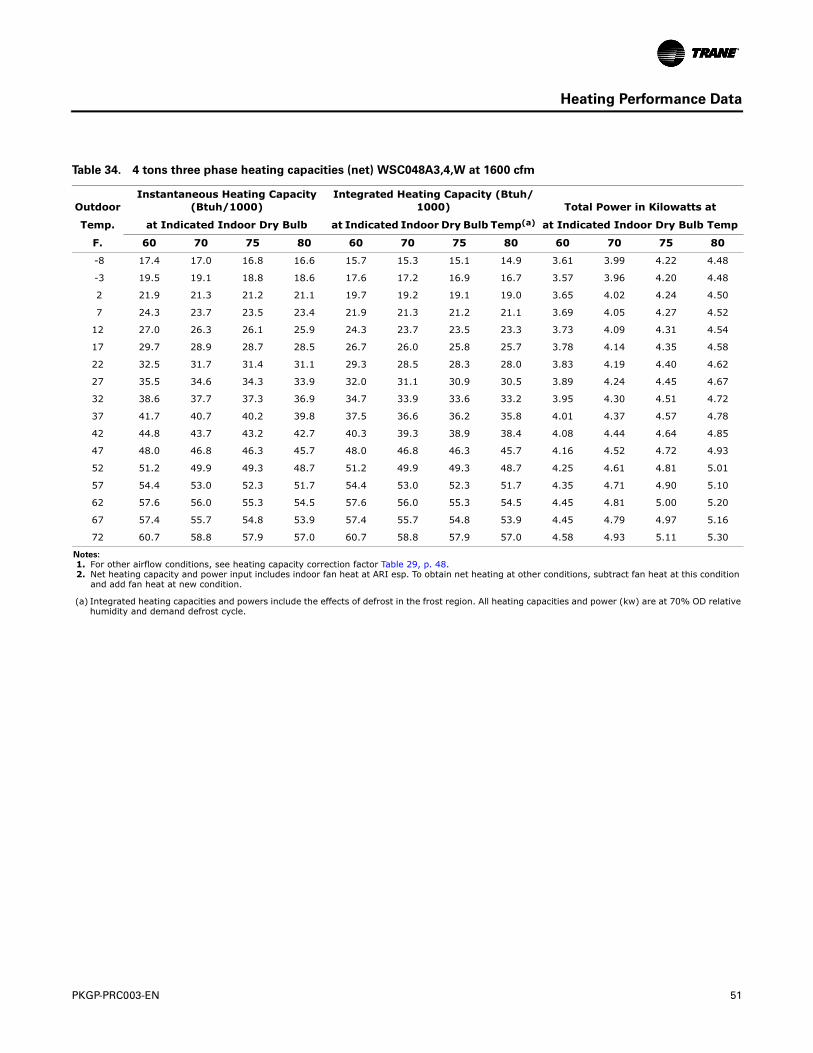
PKGP-PRC003-EN 51
Heating Performance Data
Table 34. 4 tons three phase heating capacities (net) WSC048A3,4,W at 1600 cfm
OutdoorInstantaneous Heating Capacity
(Btuh/1000)Integrated Heating Capacity (Btuh/
1000) Total Power in Kilowatts at
Temp. at Indicated Indoor Dry Bulb at Indicated Indoor Dry Bulb Temp(a) at Indicated Indoor Dry Bulb Temp
F. 60 70 75 80 60 70 75 80 60 70 75 80
-8 17.4 17.0 16.8 16.6 15.7 15.3 15.1 14.9 3.61 3.99 4.22 4.48
-3 19.5 19.1 18.8 18.6 17.6 17.2 16.9 16.7 3.57 3.96 4.20 4.48
2 21.9 21.3 21.2 21.1 19.7 19.2 19.1 19.0 3.65 4.02 4.24 4.50
7 24.3 23.7 23.5 23.4 21.9 21.3 21.2 21.1 3.69 4.05 4.27 4.52
12 27.0 26.3 26.1 25.9 24.3 23.7 23.5 23.3 3.73 4.09 4.31 4.54
17 29.7 28.9 28.7 28.5 26.7 26.0 25.8 25.7 3.78 4.14 4.35 4.58
22 32.5 31.7 31.4 31.1 29.3 28.5 28.3 28.0 3.83 4.19 4.40 4.62
27 35.5 34.6 34.3 33.9 32.0 31.1 30.9 30.5 3.89 4.24 4.45 4.67
32 38.6 37.7 37.3 36.9 34.7 33.9 33.6 33.2 3.95 4.30 4.51 4.72
37 41.7 40.7 40.2 39.8 37.5 36.6 36.2 35.8 4.01 4.37 4.57 4.78
42 44.8 43.7 43.2 42.7 40.3 39.3 38.9 38.4 4.08 4.44 4.64 4.85
47 48.0 46.8 46.3 45.7 48.0 46.8 46.3 45.7 4.16 4.52 4.72 4.93
52 51.2 49.9 49.3 48.7 51.2 49.9 49.3 48.7 4.25 4.61 4.81 5.01
57 54.4 53.0 52.3 51.7 54.4 53.0 52.3 51.7 4.35 4.71 4.90 5.10
62 57.6 56.0 55.3 54.5 57.6 56.0 55.3 54.5 4.45 4.81 5.00 5.20
67 57.4 55.7 54.8 53.9 57.4 55.7 54.8 53.9 4.45 4.79 4.97 5.16
72 60.7 58.8 57.9 57.0 60.7 58.8 57.9 57.0 4.58 4.93 5.11 5.30
Notes:
1. For other airflow conditions, see heating capacity correction factor Table 29, p. 48. 2. Net heating capacity and power input includes indoor fan heat at ARI esp. To obtain net heating at other conditions, subtract fan heat at this condition
and add fan heat at new condition.
(a) Integrated heating capacities and powers include the effects of defrost in the frost region. All heating capacities and power (kw) are at 70% OD relative humidity and demand defrost cycle.
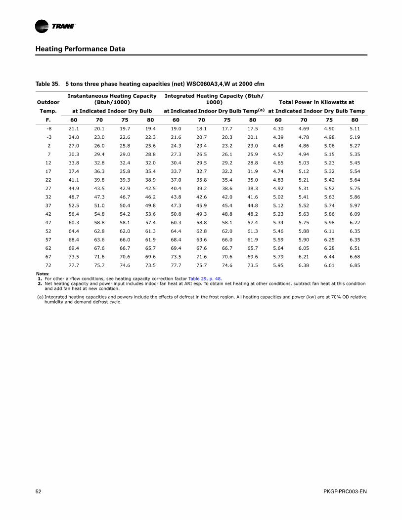
52 PKGP-PRC003-EN
Heating Performance Data
Table 35. 5 tons three phase heating capacities (net) WSC060A3,4,W at 2000 cfm
OutdoorInstantaneous Heating Capacity
(Btuh/1000)Integrated Heating Capacity (Btuh/
1000) Total Power in Kilowatts at
Temp. at Indicated Indoor Dry Bulb at Indicated Indoor Dry Bulb Temp(a) at Indicated Indoor Dry Bulb Temp
F. 60 70 75 80 60 70 75 80 60 70 75 80
-8 21.1 20.1 19.7 19.4 19.0 18.1 17.7 17.5 4.30 4.69 4.90 5.11
-3 24.0 23.0 22.6 22.3 21.6 20.7 20.3 20.1 4.39 4.78 4.98 5.19
2 27.0 26.0 25.8 25.6 24.3 23.4 23.2 23.0 4.48 4.86 5.06 5.27
7 30.3 29.4 29.0 28.8 27.3 26.5 26.1 25.9 4.57 4.94 5.15 5.35
12 33.8 32.8 32.4 32.0 30.4 29.5 29.2 28.8 4.65 5.03 5.23 5.45
17 37.4 36.3 35.8 35.4 33.7 32.7 32.2 31.9 4.74 5.12 5.32 5.54
22 41.1 39.8 39.3 38.9 37.0 35.8 35.4 35.0 4.83 5.21 5.42 5.64
27 44.9 43.5 42.9 42.5 40.4 39.2 38.6 38.3 4.92 5.31 5.52 5.75
32 48.7 47.3 46.7 46.2 43.8 42.6 42.0 41.6 5.02 5.41 5.63 5.86
37 52.5 51.0 50.4 49.8 47.3 45.9 45.4 44.8 5.12 5.52 5.74 5.97
42 56.4 54.8 54.2 53.6 50.8 49.3 48.8 48.2 5.23 5.63 5.86 6.09
47 60.3 58.8 58.1 57.4 60.3 58.8 58.1 57.4 5.34 5.75 5.98 6.22
52 64.4 62.8 62.0 61.3 64.4 62.8 62.0 61.3 5.46 5.88 6.11 6.35
57 68.4 63.6 66.0 61.9 68.4 63.6 66.0 61.9 5.59 5.90 6.25 6.35
62 69.4 67.6 66.7 65.7 69.4 67.6 66.7 65.7 5.64 6.05 6.28 6.51
67 73.5 71.6 70.6 69.6 73.5 71.6 70.6 69.6 5.79 6.21 6.44 6.68
72 77.7 75.7 74.6 73.5 77.7 75.7 74.6 73.5 5.95 6.38 6.61 6.85
Notes:
1. For other airflow conditions, see heating capacity correction factor Table 29, p. 48. 2. Net heating capacity and power input includes indoor fan heat at ARI esp. To obtain net heating at other conditions, subtract fan heat at this condition
and add fan heat at new condition.
(a) Integrated heating capacities and powers include the effects of defrost in the frost region. All heating capacities and power (kw) are at 70% OD relative humidity and demand defrost cycle.
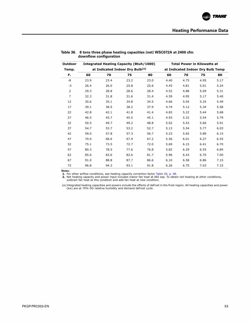
PKGP-PRC003-EN 53
Heating Performance Data
Table 36. 6 tons three phase heating capacities (net) WSC072A at 2400 cfmdownflow configuration
Outdoor Integrated Heating Capacity (Btuh/1000) Total Power in Kilowatts at
Temp. at Indicated Indoor Dry Bulb(a)
(a) Integrated heating capacities and powers include the effects of defrost in the frost region. All heating capacities and power (kw) are at 70% OD relative humidity and demand defrost cycle.
at Indicated Indoor Dry Bulb Temp
F. 60 70 75 80 60 70 75 80
-8 23.9 23.4 23.2 23.0 4.40 4.75 4.95 5.17
-3 26.4 26.0 25.8 25.6 4.45 4.81 5.01 5.24
2 29.3 28.8 28.6 28.4 4.52 4.88 5.09 5.31
7 32.3 31.8 31.6 31.4 4.59 4.95 5.17 5.40
12 35.6 35.1 34.8 34.5 4.66 5.04 5.25 5.49
17 39.1 38.5 38.2 37.9 4.74 5.12 5.34 5.58
22 42.8 42.1 41.8 41.4 4.83 5.22 5.44 5.68
27 46.5 45.7 45.5 45.1 4.93 5.32 5.54 5.79
32 50.5 49.7 49.2 48.8 5.02 5.43 5.66 5.91
37 54.7 53.7 53.2 52.7 5.13 5.54 5.77 6.03
42 59.0 57.8 57.3 56.7 5.23 5.65 5.89 6.15
47 70.0 68.6 67.9 67.2 5.56 6.01 6.27 6.55
52 75.1 73.5 72.7 72.0 5.69 6.15 6.41 6.70
57 80.3 78.5 77.6 76.8 5.82 6.29 6.55 6.84
62 85.6 83.6 82.6 81.7 5.96 6.43 6.70 7.00
67 91.0 88.8 87.7 86.6 6.10 6.58 6.86 7.15
72 96.8 94.3 93.1 91.8 6.26 6.75 7.03 7.33
Notes:
1. For other airflow conditions, see heating capacity correction factor Table 29, p. 48. 2. Net heating capacity and power input includes indoor fan heat at ARI esp. To obtain net heating at other conditions,
subtract fan heat at this condition and add fan heat at new condition.
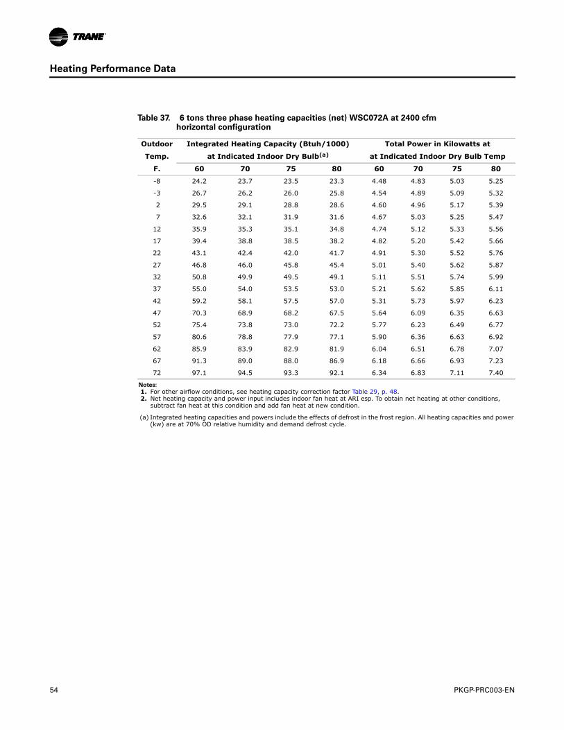
54 PKGP-PRC003-EN
Heating Performance Data
Table 37. 6 tons three phase heating capacities (net) WSC072A at 2400 cfmhorizontal configuration
Outdoor Integrated Heating Capacity (Btuh/1000) Total Power in Kilowatts at
Temp. at Indicated Indoor Dry Bulb(a)
(a) Integrated heating capacities and powers include the effects of defrost in the frost region. All heating capacities and power (kw) are at 70% OD relative humidity and demand defrost cycle.
at Indicated Indoor Dry Bulb Temp
F. 60 70 75 80 60 70 75 80
-8 24.2 23.7 23.5 23.3 4.48 4.83 5.03 5.25
-3 26.7 26.2 26.0 25.8 4.54 4.89 5.09 5.32
2 29.5 29.1 28.8 28.6 4.60 4.96 5.17 5.39
7 32.6 32.1 31.9 31.6 4.67 5.03 5.25 5.47
12 35.9 35.3 35.1 34.8 4.74 5.12 5.33 5.56
17 39.4 38.8 38.5 38.2 4.82 5.20 5.42 5.66
22 43.1 42.4 42.0 41.7 4.91 5.30 5.52 5.76
27 46.8 46.0 45.8 45.4 5.01 5.40 5.62 5.87
32 50.8 49.9 49.5 49.1 5.11 5.51 5.74 5.99
37 55.0 54.0 53.5 53.0 5.21 5.62 5.85 6.11
42 59.2 58.1 57.5 57.0 5.31 5.73 5.97 6.23
47 70.3 68.9 68.2 67.5 5.64 6.09 6.35 6.63
52 75.4 73.8 73.0 72.2 5.77 6.23 6.49 6.77
57 80.6 78.8 77.9 77.1 5.90 6.36 6.63 6.92
62 85.9 83.9 82.9 81.9 6.04 6.51 6.78 7.07
67 91.3 89.0 88.0 86.9 6.18 6.66 6.93 7.23
72 97.1 94.5 93.3 92.1 6.34 6.83 7.11 7.40
Notes:
1. For other airflow conditions, see heating capacity correction factor Table 29, p. 48. 2. Net heating capacity and power input includes indoor fan heat at ARI esp. To obtain net heating at other conditions,
subtract fan heat at this condition and add fan heat at new condition.
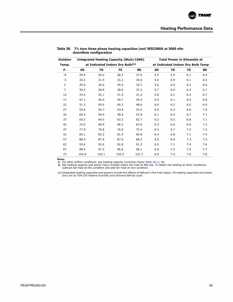
PKGP-PRC003-EN 55
Heating Performance Data
Table 38. 7½ tons three phase heating capacities (net) WSC090A at 3000 cfmdownflow configuration
Outdoor Integrated Heating Capacity (Btuh/1000) Total Power in Kilowatts at
Temp. at Indicated Indoor Dry Bulb(a)
(a) Integrated heating capacities and powers include the effects of defrost in the frost region. All heating capacities and power (kw) are at 70% OD relative humidity and demand defrost cycle.
at Indicated Indoor Dry Bulb Temp
F. 60 70 75 80 60 70 75 80
-8 29.9 29.2 28.3 27.6 5.4 5.9 6.1 6.4
-3 32.5 31.5 31.1 30.6 5.6 5.9 6.1 6.5
2 35.6 35.0 34.4 33.7 5.6 6.0 6.2 6.6
7 39.5 38.8 38.0 37.3 5.7 6.0 6.3 6.7
12 43.4 42.1 41.5 41.0 5.8 6.1 6.4 6.7
17 47.1 46.0 45.7 45.4 5.9 6.1 6.4 6.8
22 51.2 50.0 49.3 48.6 6.0 6.2 6.5 6.9
27 55.6 54.7 53.8 53.0 6.0 6.3 6.6 7.0
32 60.4 59.4 58.6 57.8 6.1 6.4 6.7 7.1
37 65.2 64.0 63.3 62.7 6.2 6.5 6.8 7.1
42 70.0 68.9 68.3 67.6 6.3 6.6 6.9 7.3
47 77.9 76.8 76.0 75.4 6.3 6.7 7.0 7.3
52 83.1 82.2 81.5 80.8 6.4 6.8 7.1 7.4
57 88.5 87.9 87.0 86.2 6.5 6.9 7.3 7.5
62 93.6 92.6 91.8 91.2 6.5 7.1 7.4 7.6
67 98.9 97.2 96.6 96.1 6.6 7.2 7.5 7.7
72 104.8 103.1 102.5 101.7 6.8 7.4 7.6 7.8
Notes:
1. For other airflow conditions, see heating capacity correction factor Table 29, p. 48. 2. Net heating capacity and power input includes indoor fan heat at ARI esp. To obtain net heating at other conditions,
subtract fan heat at this condition and add fan heat at new condition.
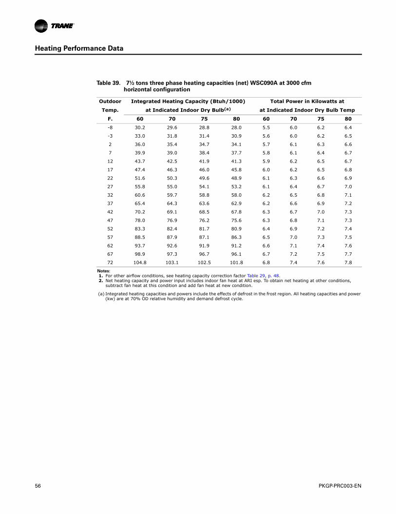
56 PKGP-PRC003-EN
Heating Performance Data
Table 39. 7½ tons three phase heating capacities (net) WSC090A at 3000 cfmhorizontal configuration
Outdoor Integrated Heating Capacity (Btuh/1000) Total Power in Kilowatts at
Temp. at Indicated Indoor Dry Bulb(a)
(a) Integrated heating capacities and powers include the effects of defrost in the frost region. All heating capacities and power (kw) are at 70% OD relative humidity and demand defrost cycle.
at Indicated Indoor Dry Bulb Temp
F. 60 70 75 80 60 70 75 80
-8 30.2 29.6 28.8 28.0 5.5 6.0 6.2 6.4
-3 33.0 31.8 31.4 30.9 5.6 6.0 6.2 6.5
2 36.0 35.4 34.7 34.1 5.7 6.1 6.3 6.6
7 39.9 39.0 38.4 37.7 5.8 6.1 6.4 6.7
12 43.7 42.5 41.9 41.3 5.9 6.2 6.5 6.7
17 47.4 46.3 46.0 45.8 6.0 6.2 6.5 6.8
22 51.6 50.3 49.6 48.9 6.1 6.3 6.6 6.9
27 55.8 55.0 54.1 53.2 6.1 6.4 6.7 7.0
32 60.6 59.7 58.8 58.0 6.2 6.5 6.8 7.1
37 65.4 64.3 63.6 62.9 6.2 6.6 6.9 7.2
42 70.2 69.1 68.5 67.8 6.3 6.7 7.0 7.3
47 78.0 76.9 76.2 75.6 6.3 6.8 7.1 7.3
52 83.3 82.4 81.7 80.9 6.4 6.9 7.2 7.4
57 88.5 87.9 87.1 86.3 6.5 7.0 7.3 7.5
62 93.7 92.6 91.9 91.2 6.6 7.1 7.4 7.6
67 98.9 97.3 96.7 96.1 6.7 7.2 7.5 7.7
72 104.8 103.1 102.5 101.8 6.8 7.4 7.6 7.8
Notes:
1. For other airflow conditions, see heating capacity correction factor Table 29, p. 48. 2. Net heating capacity and power input includes indoor fan heat at ARI esp. To obtain net heating at other conditions,
subtract fan heat at this condition and add fan heat at new condition.
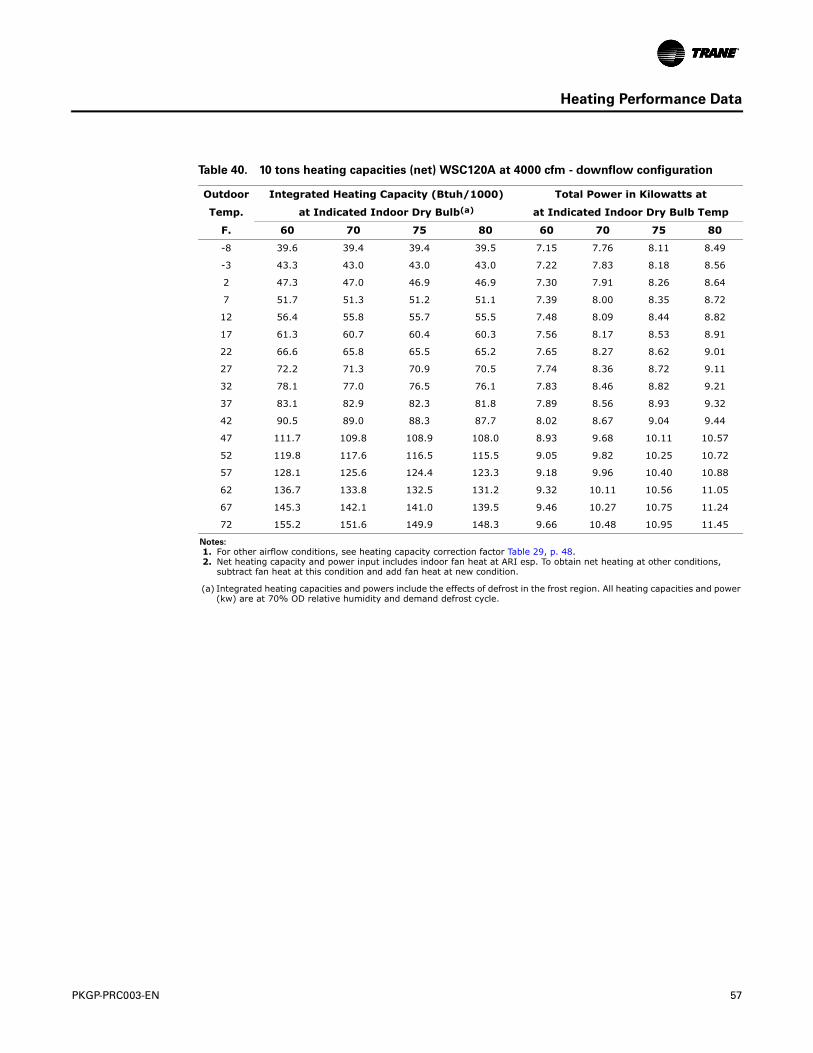
PKGP-PRC003-EN 57
Heating Performance Data
Table 40. 10 tons heating capacities (net) WSC120A at 4000 cfm - downflow configuration
Outdoor Integrated Heating Capacity (Btuh/1000) Total Power in Kilowatts at
Temp. at Indicated Indoor Dry Bulb(a)
(a) Integrated heating capacities and powers include the effects of defrost in the frost region. All heating capacities and power (kw) are at 70% OD relative humidity and demand defrost cycle.
at Indicated Indoor Dry Bulb Temp
F. 60 70 75 80 60 70 75 80
-8 39.6 39.4 39.4 39.5 7.15 7.76 8.11 8.49
-3 43.3 43.0 43.0 43.0 7.22 7.83 8.18 8.56
2 47.3 47.0 46.9 46.9 7.30 7.91 8.26 8.64
7 51.7 51.3 51.2 51.1 7.39 8.00 8.35 8.72
12 56.4 55.8 55.7 55.5 7.48 8.09 8.44 8.82
17 61.3 60.7 60.4 60.3 7.56 8.17 8.53 8.91
22 66.6 65.8 65.5 65.2 7.65 8.27 8.62 9.01
27 72.2 71.3 70.9 70.5 7.74 8.36 8.72 9.11
32 78.1 77.0 76.5 76.1 7.83 8.46 8.82 9.21
37 83.1 82.9 82.3 81.8 7.89 8.56 8.93 9.32
42 90.5 89.0 88.3 87.7 8.02 8.67 9.04 9.44
47 111.7 109.8 108.9 108.0 8.93 9.68 10.11 10.57
52 119.8 117.6 116.5 115.5 9.05 9.82 10.25 10.72
57 128.1 125.6 124.4 123.3 9.18 9.96 10.40 10.88
62 136.7 133.8 132.5 131.2 9.32 10.11 10.56 11.05
67 145.3 142.1 141.0 139.5 9.46 10.27 10.75 11.24
72 155.2 151.6 149.9 148.3 9.66 10.48 10.95 11.45
Notes:
1. For other airflow conditions, see heating capacity correction factor Table 29, p. 48. 2. Net heating capacity and power input includes indoor fan heat at ARI esp. To obtain net heating at other conditions,
subtract fan heat at this condition and add fan heat at new condition.
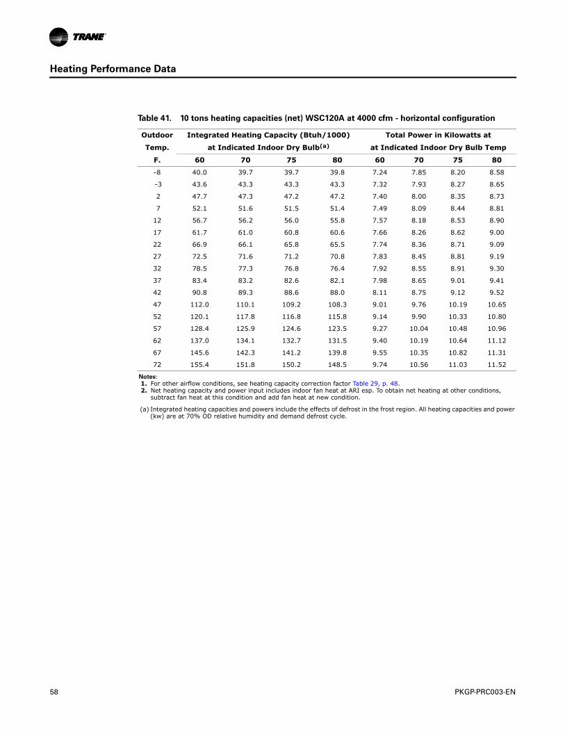
58 PKGP-PRC003-EN
Heating Performance Data
Table 41. 10 tons heating capacities (net) WSC120A at 4000 cfm - horizontal configuration
Outdoor Integrated Heating Capacity (Btuh/1000) Total Power in Kilowatts at
Temp. at Indicated Indoor Dry Bulb(a)
(a) Integrated heating capacities and powers include the effects of defrost in the frost region. All heating capacities and power (kw) are at 70% OD relative humidity and demand defrost cycle.
at Indicated Indoor Dry Bulb Temp
F. 60 70 75 80 60 70 75 80
-8 40.0 39.7 39.7 39.8 7.24 7.85 8.20 8.58
-3 43.6 43.3 43.3 43.3 7.32 7.93 8.27 8.65
2 47.7 47.3 47.2 47.2 7.40 8.00 8.35 8.73
7 52.1 51.6 51.5 51.4 7.49 8.09 8.44 8.81
12 56.7 56.2 56.0 55.8 7.57 8.18 8.53 8.90
17 61.7 61.0 60.8 60.6 7.66 8.26 8.62 9.00
22 66.9 66.1 65.8 65.5 7.74 8.36 8.71 9.09
27 72.5 71.6 71.2 70.8 7.83 8.45 8.81 9.19
32 78.5 77.3 76.8 76.4 7.92 8.55 8.91 9.30
37 83.4 83.2 82.6 82.1 7.98 8.65 9.01 9.41
42 90.8 89.3 88.6 88.0 8.11 8.75 9.12 9.52
47 112.0 110.1 109.2 108.3 9.01 9.76 10.19 10.65
52 120.1 117.8 116.8 115.8 9.14 9.90 10.33 10.80
57 128.4 125.9 124.6 123.5 9.27 10.04 10.48 10.96
62 137.0 134.1 132.7 131.5 9.40 10.19 10.64 11.12
67 145.6 142.3 141.2 139.8 9.55 10.35 10.82 11.31
72 155.4 151.8 150.2 148.5 9.74 10.56 11.03 11.52
Notes:
1. For other airflow conditions, see heating capacity correction factor Table 29, p. 48. 2. Net heating capacity and power input includes indoor fan heat at ARI esp. To obtain net heating at other conditions,
subtract fan heat at this condition and add fan heat at new condition.
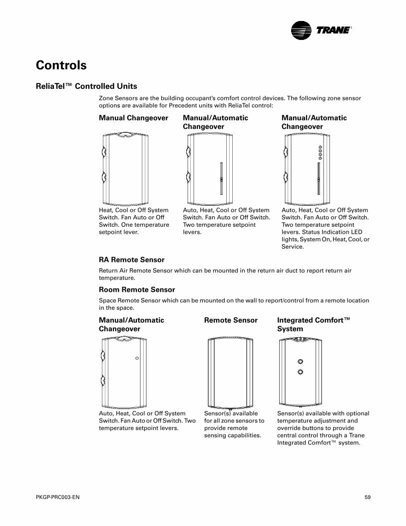
PKGP-PRC003-EN 59
Controls
ReliaTel™ Controlled Units
Zone Sensors are the building occupant’s comfort control devices. The following zone sensor options are available for Precedent units with ReliaTel control:
RA Remote Sensor
Return Air Remote Sensor which can be mounted in the return air duct to report return air temperature.
Room Remote Sensor
Space Remote Sensor which can be mounted on the wall to report/control from a remote location in the space.
Manual Changeover Manual/Automatic
Changeover
Manual/Automatic
Changeover
Heat, Cool or Off System Switch. Fan Auto or Off Switch. One temperature setpoint lever.
Auto, Heat, Cool or Off System Switch. Fan Auto or Off Switch. Two temperature setpoint levers.
Auto, Heat, Cool or Off System Switch. Fan Auto or Off Switch. Two temperature setpoint levers. Status Indication LED lights, System On, Heat, Cool, or Service.
Manual/Automatic
Changeover
Remote Sensor Integrated Comfort™
System
Auto, Heat, Cool or Off System Switch. Fan Auto or Off Switch. Two temperature setpoint levers.
Sensor(s) available for all zone sensors to provide remote sensing capabilities.
Sensor(s) available with optional temperature adjustment and override buttons to provide central control through a Trane Integrated Comfort™ system.
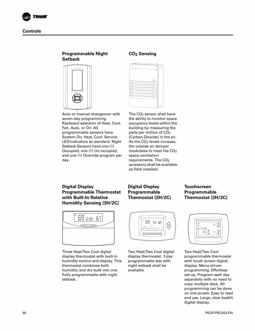
60 PKGP-PRC003-EN
Controls
Programmable Night
Setback
CO2 Sensing
Auto or manual changeover with seven-day programming. Keyboard selection of Heat, Cool, Fan, Auto, or On. All programmable sensors have System On, Heat, Cool, Service LED/indicators as standard. Night Setback Sensors have one (1) Occupied, one (1) Un-occupied, and one (1) Override program per day.
The CO2 sensor shall have the ability to monitor space occupancy levels within the building by measuring the parts per million of CO2 (Carbon Dioxide) in the air. As the CO2 levels increase, the outside air damper modulates to meet the CO2 space ventilation requirements. The CO2 accessory shall be available as field installed.
Digital Display
Programmable Thermostat
with Built-In Relative
Humidity Sensing (3H/2C)
Digital Display
Programmable
Thermostat (2H/2C)
Touchscreen
Programmable
Thermostat (2H/2C)
Three Heat/Two Cool digital display thermostat with built-in humidity control and display. This thermostat combines both humidity and dry bulb into one. Fully programmable with night setback.
Two Heat/Two Cool digital display thermostat. 7-day programmable stat with night setback shall be available.
Two Heat/Two Cool programmable thermostat with touch screen digital display. Menu-driven programming. Effortless set-up. Program each day separately with no need to copy multiple days. All programming can be done on one screen. Easy to read and use. Large, clear backlit digital display.
Tue
System & Fan Override More
Tue
Heat Auto
Hold Until
DONE WAKE LEAVE RETURN SLEEPEDIT CANCEL
MON TUE WED THU FRI SAT SUN
PM
FANON
AUTOCIRC
SYSTEMEM HEAT
HEATOFF
COOLAUTO
RESET
HEAT
COOL
DEHUMIDIFIERCANCELPERIOD
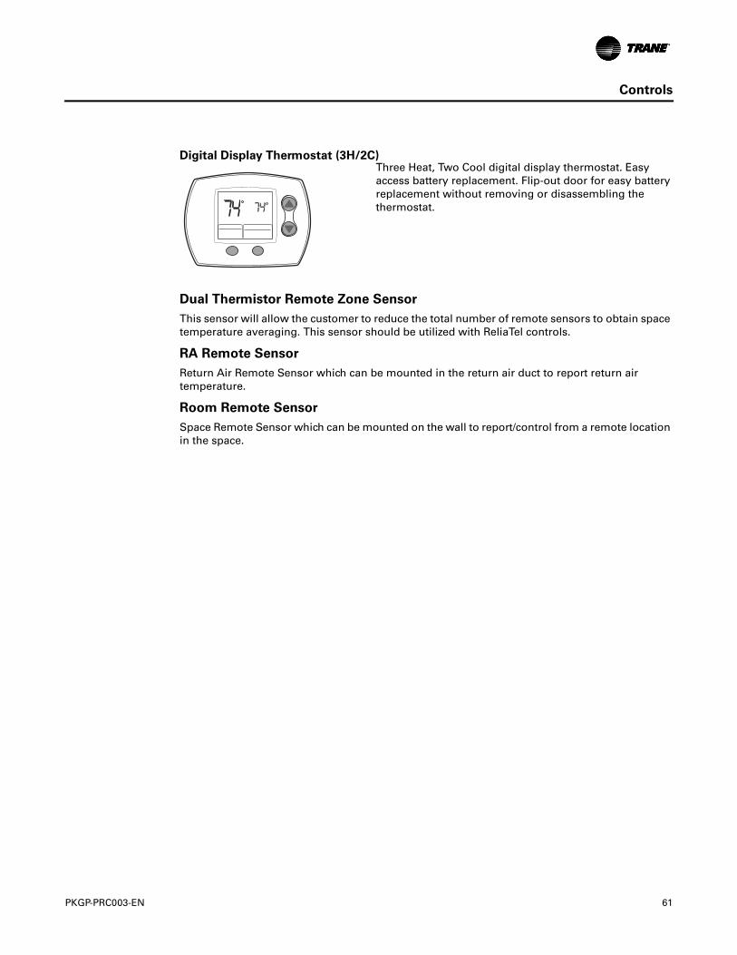
PKGP-PRC003-EN 61
Controls
Dual Thermistor Remote Zone Sensor
This sensor will allow the customer to reduce the total number of remote sensors to obtain space temperature averaging. This sensor should be utilized with ReliaTel controls.
RA Remote Sensor
Return Air Remote Sensor which can be mounted in the return air duct to report return air temperature.
Room Remote Sensor
Space Remote Sensor which can be mounted on the wall to report/control from a remote location in the space.
Digital Display Thermostat (3H/2C)Three Heat, Two Cool digital display thermostat. Easy access battery replacement. Flip-out door for easy battery replacement without removing or disassembling the thermostat.
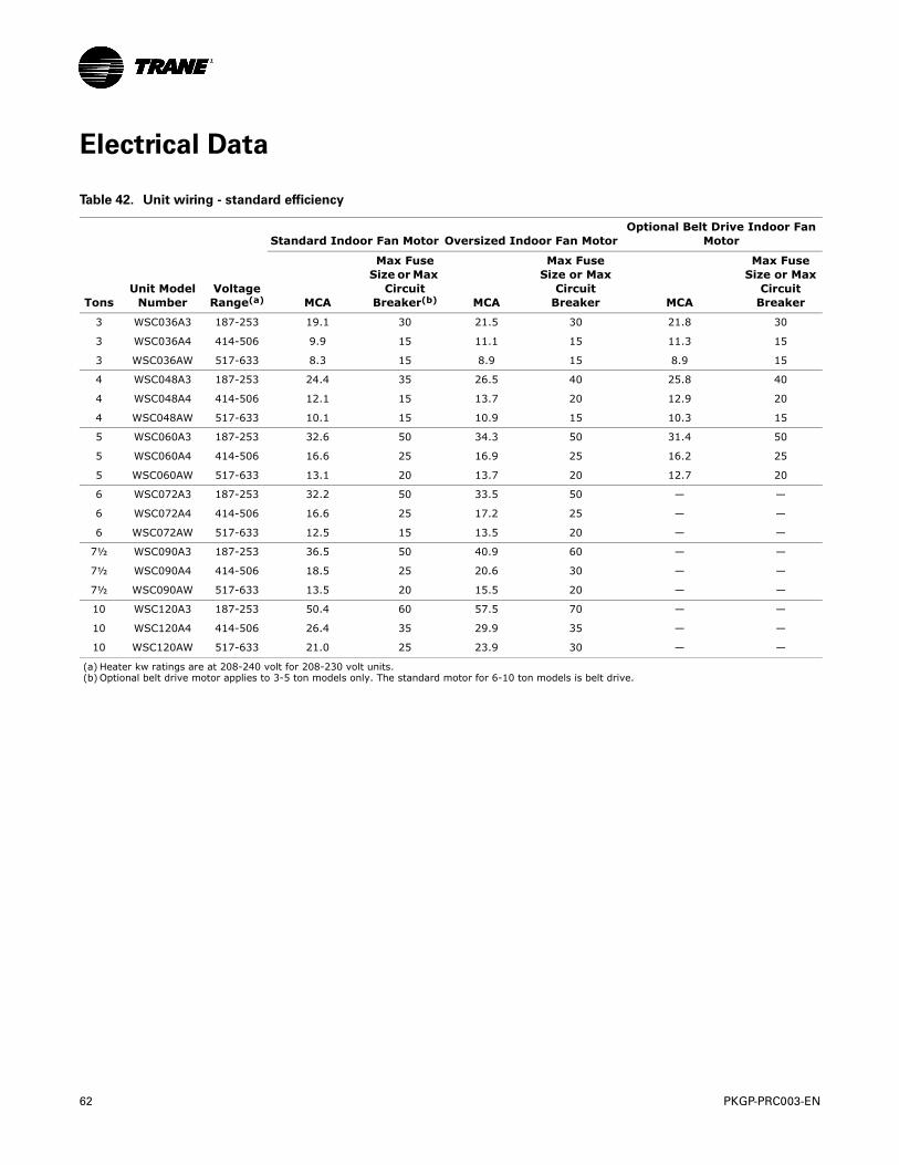
62 PKGP-PRC003-EN
Electrical Data
Table 42. Unit wiring - standard efficiency
Standard Indoor Fan Motor Oversized Indoor Fan MotorOptional Belt Drive Indoor Fan
Motor
TonsUnit Model
NumberVoltageRange(a) MCA
Max Fuse Size or Max
Circuit Breaker(b) MCA
Max Fuse Size or Max
Circuit Breaker MCA
Max Fuse Size or Max
Circuit Breaker
3 WSC036A3 187-253 19.1 30 21.5 30 21.8 30
3 WSC036A4 414-506 9.9 15 11.1 15 11.3 15
3 WSC036AW 517-633 8.3 15 8.9 15 8.9 15
4 WSC048A3 187-253 24.4 35 26.5 40 25.8 40
4 WSC048A4 414-506 12.1 15 13.7 20 12.9 20
4 WSC048AW 517-633 10.1 15 10.9 15 10.3 15
5 WSC060A3 187-253 32.6 50 34.3 50 31.4 50
5 WSC060A4 414-506 16.6 25 16.9 25 16.2 25
5 WSC060AW 517-633 13.1 20 13.7 20 12.7 20
6 WSC072A3 187-253 32.2 50 33.5 50 — —
6 WSC072A4 414-506 16.6 25 17.2 25 — —
6 WSC072AW 517-633 12.5 15 13.5 20 — —
7½ WSC090A3 187-253 36.5 50 40.9 60 — —
7½ WSC090A4 414-506 18.5 25 20.6 30 — —
7½ WSC090AW 517-633 13.5 20 15.5 20 — —
10 WSC120A3 187-253 50.4 60 57.5 70 — —
10 WSC120A4 414-506 26.4 35 29.9 35 — —
10 WSC120AW 517-633 21.0 25 23.9 30 — —
(a) Heater kw ratings are at 208-240 volt for 208-230 volt units.(b) Optional belt drive motor applies to 3-5 ton models only. The standard motor for 6-10 ton models is belt drive.
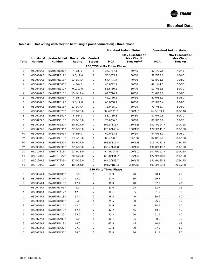
PKGP-PRC003-EN 63
Electrical Data
Table 43. Unit wiring with electric heat (single point connection) - three phase
Standard Indoor Motor Oversized Indoor Motor
TonsUnit Model
NumberHeater Model
NumberHeater kW
RatingControl Stages MCA
Max Fuse Size or Max Circuit Breaker(a) MCA
Max Fuse Size or Max Circuit
Breaker
208/230 Volts Three Phase
3 WSC036A3 BAYHTRR306* 4.5/6.0 1 34.7/37.1 40/45 37.1/39.5 45/45
3 WSC036A3 BAYHTRR312* 9.0/12.0 2 50.3/55.2 60/60 52.7/57.6 60/60
3 WSC036A3 BAYHTRR318* 13.1/17.4 2 64.4/71.4 70/80 66.8/73.8 70/80
4 WSC048A3 BAYHTRR306* 4.5/6.0 1 40.0/42.4 50/50 42.1/44.5 50/50
4 WSC048A3 BAYHTRR312* 9.0/12.0 2 55.6/60.5 60/70 57.7/62.6 60/70
4 WSC048A3 BAYHTRR318* 13.1/17.4 2 69.7/76.7 70/80 71.8/78.8 80/80
5 WSC060A3 BAYHTRR306* 4.5/6.0 1 48.2/50.6 60/60 49.9/52.3 60/60
5 WSC060A3 BAYHTRR312* 9.0/12.0 2 63.8/68.7 70/80 65.5/70.4 70/80
5 WSC060A3 BAYHTRR318* 13.1/17.4 2 78.0/85.0 80/90 79.7/86.7 80/90
5 WSC060A3 BAYHTRR323* 17.3/23.0 2 92.6/101.7 100/110 94.3/103.4 100/110
6 WSC072A3 BAYHTRS309* 6.8/9.0 1 55.7/59.3 60/60 57.0/60.6 60/70
6 WSC072A3 BAYHTRS318* 13.5/18.0 1 79.0/86.3 80/90 80.3/87.6 90/90
6 WSC072A3 BAYHTRS327* 20.3/27.0 2 102.5/113.4 110/125 103.8/114.7 110/125
6 WSC072A3 BAYHTRS336* 27.0/36.0 2 126.0/140.4 150/150 127.3/141.7 150/150
7½ WSC090A3 BAYHTRS309* 6.8/9.0 1 60.0/63.6 60/90 64.4/68.0 80/80
7½ WSC090A3 BAYHTRS318* 13.5/18.0 1 83.4/90.6 90/100 87.8/95.0 100/100
7½ WSC090A3 BAYHTRS327* 20.3/27.0 2 106.9/117.8 110/125 113.3/122.2 125/125
7½ WSC090A3 BAYHTRS336* 27.0/36.0 2 130.4/144.8 150/150 134.8/149.2 150/150
10 WSC120A3 BAYHTRT318* 13.5/18.0 1 97.3/104.6 100/110 104.4/111.7 110/125
10 WSC120A3 BAYHTRT327* 20.3/27.0 2 120.8/131.7 125/150 127.9/138.8 150/150
10 WSC120A3 BAYHTRT336* 27.0/36.0 2 144.3/158.7 150/175 151.4/165.8 175/175
10 WSC120A3 BAYHTRT354* 40.6/54.0 2 191.2/180.3 200/200 198.3/187.4 200/200
480 Volts Three Phase
3 WSC036A4 BAYHTRR406* 6.0 1 18.9 20 20.1 25
3 WSC036A4 BAYHTRR412* 12.0 2 27.9 30 29.1 30
3 WSC036A4 BAYHTRR418* 17.4 2 36.0 40 37.2 40
4 WSC048A4 BAYHTRR406* 6.0 1 21.0 25 22.7 25
4 WSC048A4 BAYHTRR412* 12.0 2 30.1 35 31.7 35
4 WSC048A4 BAYHTRR418* 17.4 2 38.3 40 39.9 40
5 WSC060A4 BAYHTRR406* 6.0 1 25.6 30 25.9 30
5 WSC060A4 BAYHTRR412* 12.0 2 34.6 40 34.9 40
5 WSC060A4 BAYHTRR418* 17.4 2 42.7 45 43.0 45
5 WSC060A4 BAYHTRR423* 23.0 2 51.2 60 51.5 60
6 WSC072A4 BAYHTRS409* 9.0 1 30.1 35 30.7 35
6 WSC072A4 BAYHTRS418* 18.0 1 43.8 45 44.4 45
6 WSC072A4 BAYHTRS427* 27.0 2 57.3 60 57.9 60
6 WSC072A4 BAYHTRS436* 36.0 2 70.8 80 71.4 80
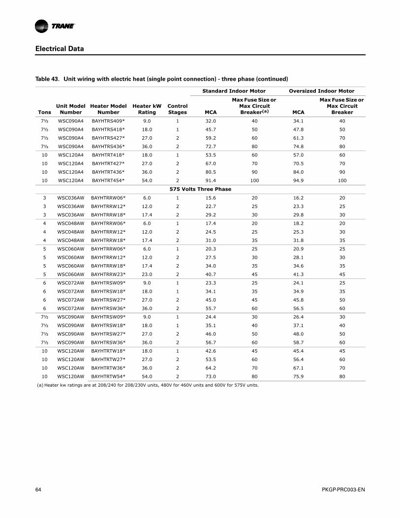
64 PKGP-PRC003-EN
Electrical Data
7½ WSC090A4 BAYHTRS409* 9.0 1 32.0 40 34.1 40
7½ WSC090A4 BAYHTRS418* 18.0 1 45.7 50 47.8 50
7½ WSC090A4 BAYHTRS427* 27.0 2 59.2 60 61.3 70
7½ WSC090A4 BAYHTRS436* 36.0 2 72.7 80 74.8 80
10 WSC120A4 BAYHTRT418* 18.0 1 53.5 60 57.0 60
10 WSC120A4 BAYHTRT427* 27.0 2 67.0 70 70.5 70
10 WSC120A4 BAYHTRT436* 36.0 2 80.5 90 84.0 90
10 WSC120A4 BAYHTRT454* 54.0 2 91.4 100 94.9 100
575 Volts Three Phase
3 WSC036AW BAYHTRRW06* 6.0 1 15.6 20 16.2 20
3 WSC036AW BAYHTRRW12* 12.0 2 22.7 25 23.3 25
3 WSC036AW BAYHTRRW18* 17.4 2 29.2 30 29.8 30
4 WSC048AW BAYHTRRW06* 6.0 1 17.4 20 18.2 20
4 WSC048AW BAYHTRRW12* 12.0 2 24.5 25 25.3 30
4 WSC048AW BAYHTRRW18* 17.4 2 31.0 35 31.8 35
5 WSC060AW BAYHTRRW06* 6.0 1 20.3 25 20.9 25
5 WSC060AW BAYHTRRW12* 12.0 2 27.5 30 28.1 30
5 WSC060AW BAYHTRRW18* 17.4 2 34.0 35 34.6 35
5 WSC060AW BAYHTRRW23* 23.0 2 40.7 45 41.3 45
6 WSC072AW BAYHTRSW09* 9.0 1 23.3 25 24.1 25
6 WSC072AW BAYHTRSW18* 18.0 1 34.1 35 34.9 35
6 WSC072AW BAYHTRSW27* 27.0 2 45.0 45 45.8 50
6 WSC072AW BAYHTRSW36* 36.0 2 55.7 60 56.5 60
7½ WSC090AW BAYHTRSW09* 9.0 1 24.4 30 26.4 30
7½ WSC090AW BAYHTRSW18* 18.0 1 35.1 40 37.1 40
7½ WSC090AW BAYHTRSW27* 27.0 2 46.0 50 48.0 50
7½ WSC090AW BAYHTRSW36* 36.0 2 56.7 60 58.7 60
10 WSC120AW BAYHTRTW18* 18.0 1 42.6 45 45.4 45
10 WSC120AW BAYHTRTW27* 27.0 2 53.5 60 56.4 60
10 WSC120AW BAYHTRTW36* 36.0 2 64.2 70 67.1 70
10 WSC120AW BAYHTRTW54* 54.0 2 73.0 80 75.9 80
(a) Heater kw ratings are at 208/240 for 208/230V units, 480V for 460V units and 600V for 575V units.
Table 43. Unit wiring with electric heat (single point connection) - three phase (continued)
Standard Indoor Motor Oversized Indoor Motor
TonsUnit Model
NumberHeater Model
NumberHeater kW
RatingControl Stages MCA
Max Fuse Size or Max Circuit Breaker(a) MCA
Max Fuse Size or Max Circuit
Breaker
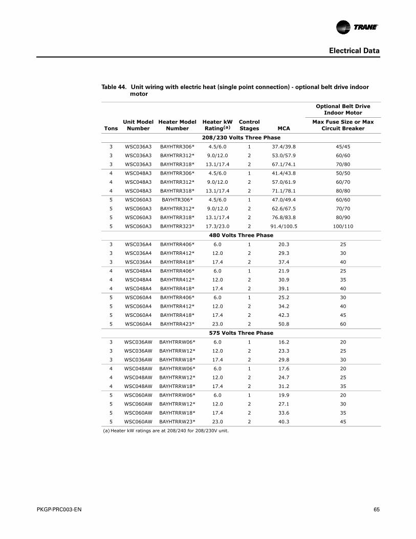
PKGP-PRC003-EN 65
Electrical Data
Table 44. Unit wiring with electric heat (single point connection) - optional belt drive indoor motor
Optional Belt Drive
Indoor Motor
TonsUnit Model
NumberHeater Model
NumberHeater kW Rating(a)
(a) Heater kW ratings are at 208/240 for 208/230V unit.
Control Stages MCA
Max Fuse Size or Max Circuit Breaker
208/230 Volts Three Phase
3 WSC036A3 BAYHTRR306* 4.5/6.0 1 37.4/39.8 45/45
3 WSC036A3 BAYHTRR312* 9.0/12.0 2 53.0/57.9 60/60
3 WSC036A3 BAYHTRR318* 13.1/17.4 2 67.1/74.1 70/80
4 WSC048A3 BAYHTRR306* 4.5/6.0 1 41.4/43.8 50/50
4 WSC048A3 BAYHTRR312* 9.0/12.0 2 57.0/61.9 60/70
4 WSC048A3 BAYHTRR318* 13.1/17.4 2 71.1/78.1 80/80
5 WSC060A3 BAYHTR306* 4.5/6.0 1 47.0/49.4 60/60
5 WSC060A3 BAYHTRR312* 9.0/12.0 2 62.6/67.5 70/70
5 WSC060A3 BAYHTRR318* 13.1/17.4 2 76.8/83.8 80/90
5 WSC060A3 BAYHTRR323* 17.3/23.0 2 91.4/100.5 100/110
480 Volts Three Phase
3 WSC036A4 BAYHTRR406* 6.0 1 20.3 25
3 WSC036A4 BAYHTRR412* 12.0 2 29.3 30
3 WSC036A4 BAYHTRR418* 17.4 2 37.4 40
4 WSC048A4 BAYHTRR406* 6.0 1 21.9 25
4 WSC048A4 BAYHTRR412* 12.0 2 30.9 35
4 WSC048A4 BAYHTRR418* 17.4 2 39.1 40
5 WSC060A4 BAYHTRR406* 6.0 1 25.2 30
5 WSC060A4 BAYHTRR412* 12.0 2 34.2 40
5 WSC060A4 BAYHTRR418* 17.4 2 42.3 45
5 WSC060A4 BAYHTRR423* 23.0 2 50.8 60
575 Volts Three Phase
3 WSC036AW BAYHTRRW06* 6.0 1 16.2 20
3 WSC036AW BAYHTRRW12* 12.0 2 23.3 25
3 WSC036AW BAYHTRRW18* 17.4 2 29.8 30
4 WSC048AW BAYHTRRW06* 6.0 1 17.6 20
4 WSC048AW BAYHTRRW12* 12.0 2 24.7 25
4 WSC048AW BAYHTRRW18* 17.4 2 31.2 35
5 WSC060AW BAYHTRRW06* 6.0 1 19.9 20
5 WSC060AW BAYHTRRW12* 12.0 2 27.1 30
5 WSC060AW BAYHTRRW18* 17.4 2 33.6 35
5 WSC060AW BAYHTRRW23* 23.0 2 40.3 45
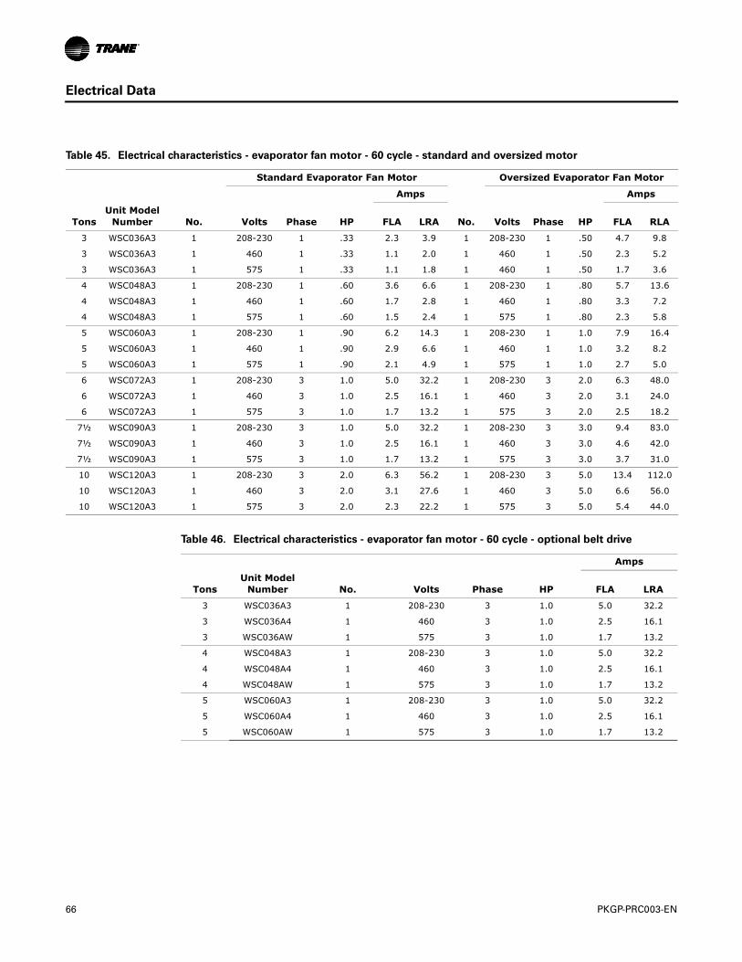
66 PKGP-PRC003-EN
Electrical Data
Table 45. Electrical characteristics - evaporator fan motor - 60 cycle - standard and oversized motor
Standard Evaporator Fan Motor Oversized Evaporator Fan Motor
Amps Amps
TonsUnit Model
Number No. Volts Phase HP FLA LRA No. Volts Phase HP FLA RLA
3 WSC036A3 1 208-230 1 .33 2.3 3.9 1 208-230 1 .50 4.7 9.8
3 WSC036A3 1 460 1 .33 1.1 2.0 1 460 1 .50 2.3 5.2
3 WSC036A3 1 575 1 .33 1.1 1.8 1 460 1 .50 1.7 3.6
4 WSC048A3 1 208-230 1 .60 3.6 6.6 1 208-230 1 .80 5.7 13.6
4 WSC048A3 1 460 1 .60 1.7 2.8 1 460 1 .80 3.3 7.2
4 WSC048A3 1 575 1 .60 1.5 2.4 1 575 1 .80 2.3 5.8
5 WSC060A3 1 208-230 1 .90 6.2 14.3 1 208-230 1 1.0 7.9 16.4
5 WSC060A3 1 460 1 .90 2.9 6.6 1 460 1 1.0 3.2 8.2
5 WSC060A3 1 575 1 .90 2.1 4.9 1 575 1 1.0 2.7 5.0
6 WSC072A3 1 208-230 3 1.0 5.0 32.2 1 208-230 3 2.0 6.3 48.0
6 WSC072A3 1 460 3 1.0 2.5 16.1 1 460 3 2.0 3.1 24.0
6 WSC072A3 1 575 3 1.0 1.7 13.2 1 575 3 2.0 2.5 18.2
7½ WSC090A3 1 208-230 3 1.0 5.0 32.2 1 208-230 3 3.0 9.4 83.0
7½ WSC090A3 1 460 3 1.0 2.5 16.1 1 460 3 3.0 4.6 42.0
7½ WSC090A3 1 575 3 1.0 1.7 13.2 1 575 3 3.0 3.7 31.0
10 WSC120A3 1 208-230 3 2.0 6.3 56.2 1 208-230 3 5.0 13.4 112.0
10 WSC120A3 1 460 3 2.0 3.1 27.6 1 460 3 5.0 6.6 56.0
10 WSC120A3 1 575 3 2.0 2.3 22.2 1 575 3 5.0 5.4 44.0
Table 46. Electrical characteristics - evaporator fan motor - 60 cycle - optional belt drive
Amps
TonsUnit Model
Number No. Volts Phase HP FLA LRA
3 WSC036A3 1 208-230 3 1.0 5.0 32.2
3 WSC036A4 1 460 3 1.0 2.5 16.1
3 WSC036AW 1 575 3 1.0 1.7 13.2
4 WSC048A3 1 208-230 3 1.0 5.0 32.2
4 WSC048A4 1 460 3 1.0 2.5 16.1
4 WSC048AW 1 575 3 1.0 1.7 13.2
5 WSC060A3 1 208-230 3 1.0 5.0 32.2
5 WSC060A4 1 460 3 1.0 2.5 16.1
5 WSC060AW 1 575 3 1.0 1.7 13.2
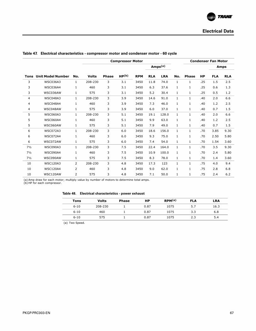
PKGP-PRC003-EN 67
Electrical Data
Table 47. Electrical characteristics - compressor motor and condenser motor - 60 cycle
Compressor Motor Condenser Fan Motor
Amps(a) Amps
Tons Unit Model Number No. Volts Phase HP(b) RPM RLA LRA No. Phase HP FLA RLA
3 WSC036A3 1 208-230 3 3.1 3450 11.8 74.0 1 1 .25 1.5 2.5
3 WSC036A4 1 460 3 3.1 3450 6.3 37.6 1 1 .25 0.6 1.3
3 WSC036AW 1 575 3 3.1 3450 5.2 30.4 1 1 .25 0.5 1.2
4 WSC048A3 1 208-230 3 3.9 3450 14.6 91.0 1 1 .40 2.0 6.6
4 WSC048A4 1 460 3 3.9 3450 7.3 46.0 1 1 .40 1.2 2.5
4 WSC048AW 1 575 3 3.9 3450 6.0 37.0 1 1 .40 0.7 1.5
5 WSC060A3 1 208-230 3 5.1 3450 19.1 128.0 1 1 .40 2.0 6.6
5 WSC060A4 1 460 3 5.1 3450 9.9 63.0 1 1 .40 1.2 2.5
5 WSC060AW 1 575 3 5.1 3450 7.9 49.0 1 1 .40 0.7 1.5
6 WSC072A3 1 208-230 3 6.0 3450 18.6 156.0 1 1 .70 3.85 9.30
6 WSC072A4 1 460 3 6.0 3450 9.3 75.0 1 1 .70 2.50 5.80
6 WSC072AW 1 575 3 6.0 3450 7.4 54.0 1 1 .70 1.54 3.60
7½ WSC090A3 1 208-230 3 7.5 3450 22.4 164.0 1 1 .70 3.5 9.30
7½ WSC090A4 1 460 3 7.5 3450 10.9 100.0 1 1 .70 2.4 5.80
7½ WSC090AW 1 575 3 7.5 3450 8.3 78.0 1 1 .70 1.4 3.60
10 WSC120A3 2 208-230 3 4.8 3450 17.3 123 1 1 .75 4.0 9.4
10 WSC120A4 2 460 3 4.8 3450 9.0 62.0 1 1 .75 2.8 6.8
10 WSC120AW 2 575 3 4.8 3450 7.1 50.0 1 1 .75 2.4 6.2
(a) Amp draw for each motor; multiply value by number of motors to determine total amps.(b) HP for each compressor.
Table 48. Electrical characteristics - power exhaust
Tons Volts Phase HP RPM(a)
(a) Two Speed.
FLA LRA
6-10 208-230 1 0.87 1075 5.7 16.3
6-10 460 1 0.87 1075 3.3 6.8
6-10 575 1 0.87 1075 2.3 5.4
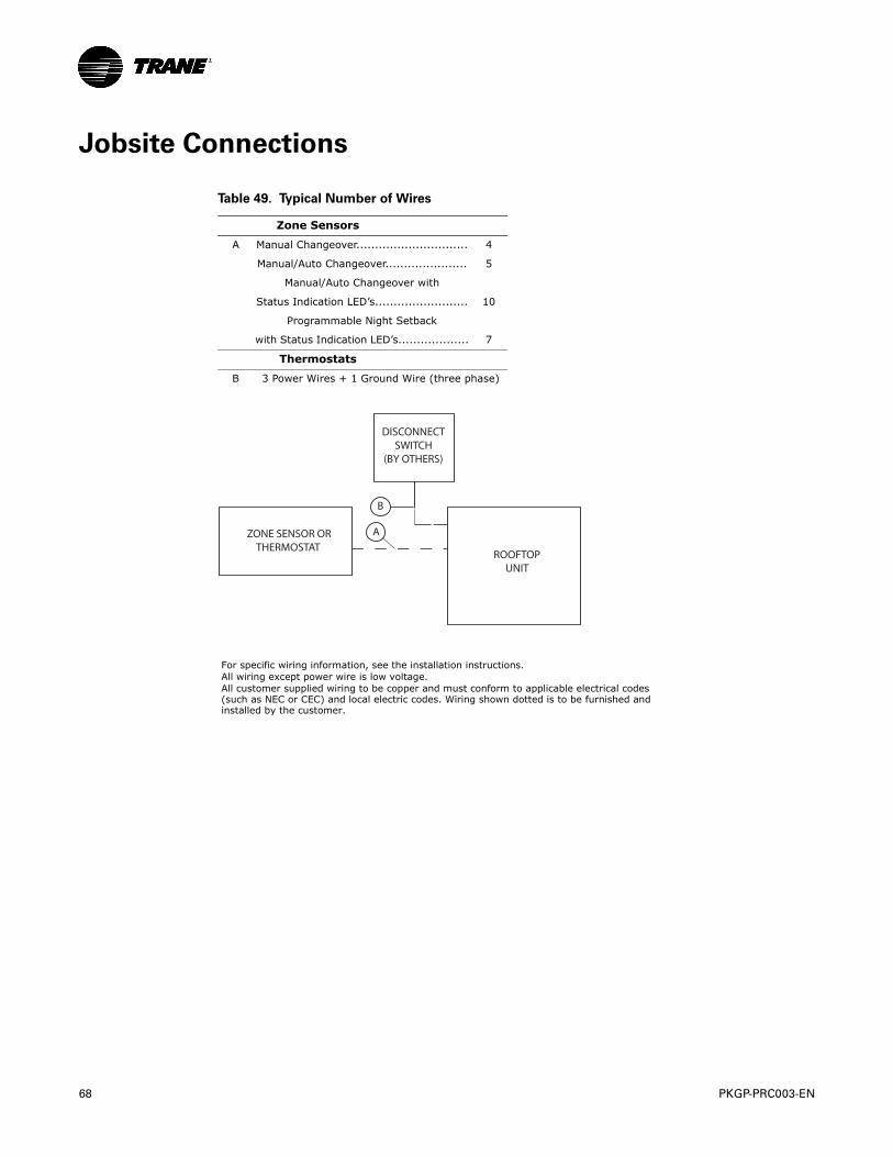
68 PKGP-PRC003-EN
Jobsite Connections
Table 49. Typical Number of Wires
Zone Sensors
A Manual Changeover.............................. 4
Manual/Auto Changeover...................... 5
Manual/Auto Changeover with
Status Indication LED’s......................... 10
Programmable Night Setback
with Status Indication LED’s................... 7
Thermostats
B 3 Power Wires + 1 Ground Wire (three phase)
For specific wiring information, see the installation instructions.All wiring except power wire is low voltage.All customer supplied wiring to be copper and must conform to applicable electrical codes(such as NEC or CEC) and local electric codes. Wiring shown dotted is to be furnished andinstalled by the customer.
DISCONNECT SWITCH
(BY OTHERS)
ZONE SENSOR OR THERMOSTAT
ROOFTOPUNIT
A
B
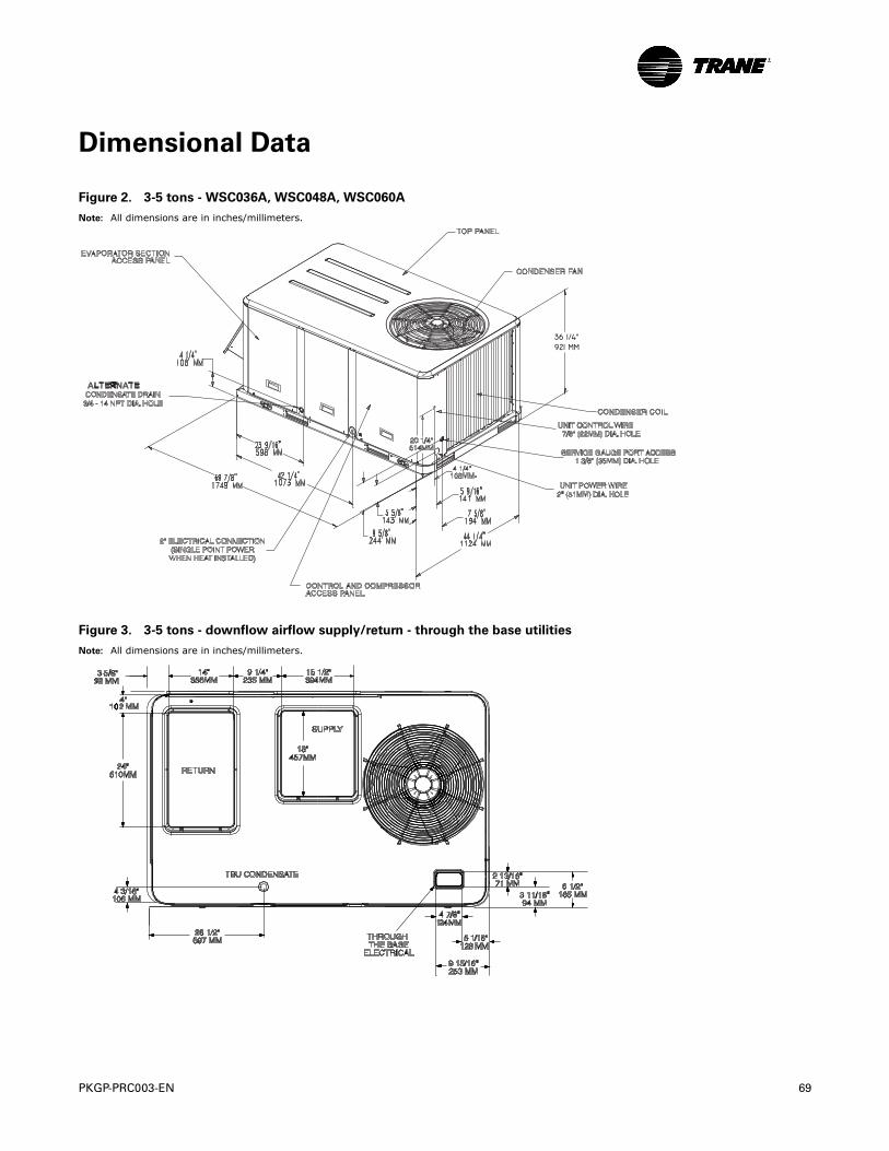
PKGP-PRC003-EN 69
Dimensional Data
Figure 2. 3-5 tons - WSC036A, WSC048A, WSC060A
Note: All dimensions are in inches/millimeters.
Figure 3. 3-5 tons - downflow airflow supply/return - through the base utilities
Note: All dimensions are in inches/millimeters.
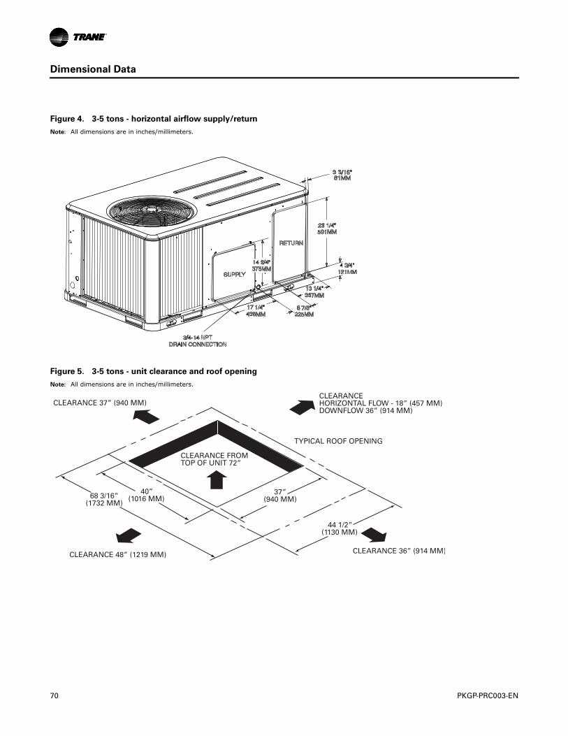
70 PKGP-PRC003-EN
Dimensional Data
Figure 4. 3-5 tons - horizontal airflow supply/return
Note: All dimensions are in inches/millimeters.
Figure 5. 3-5 tons - unit clearance and roof opening
Note: All dimensions are in inches/millimeters.
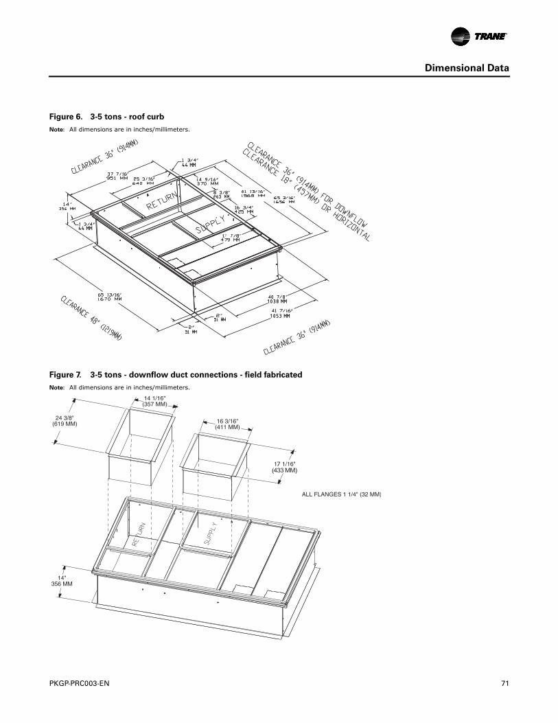
PKGP-PRC003-EN 71
Dimensional Data
Figure 6. 3-5 tons - roof curb
Note: All dimensions are in inches/millimeters.
7
4444 MMMM
4444 MMMM
10381038 MMMM
10531053 MMMM
Figure 7. 3-5 tons - downflow duct connections - field fabricated
Note: All dimensions are in inches/millimeters.
7 (433 MM)
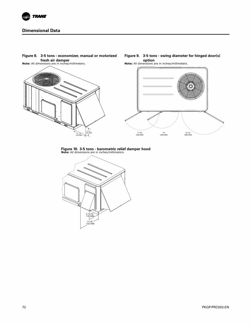
72 PKGP-PRC003-EN
Dimensional Data
Figure 8. 3-5 tons - economizer, manual or motorized
fresh air damper
Figure 9. 3-5 tons - swing diameter for hinged door(s)
optionNote: All dimensions are in inches/millimeters. Note: All dimensions are in inches/millimeters.
17 7/8"(448 MM)
16"(406 MM)
22 1/4"(565 MM)
Figure 10. 3-5 tons - barometric relief damper hoodNote: All dimensions are in inches/millimeters.
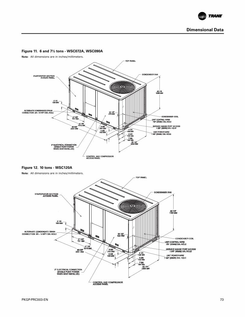
PKGP-PRC003-EN 73
Dimensional Data
Figure 11. 6 and 7½ tons - WSC072A, WSC090A
Note: All dimensions are in inches/millimeters.
Figure 12. 10 tons - WSC120A
Note: All dimensions are in inches/millimeters.
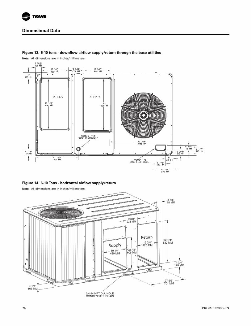
74 PKGP-PRC003-EN
Dimensional Data
Figure 13. 6-10 tons - downflow airflow supply/return through the base utilities
Note: All dimensions are in inches/millimeters.
Figure 14. 6-10 Tons - horizontal airflow supply/return
Note: All dimensions are in inches/millimeters.
Supply
Return
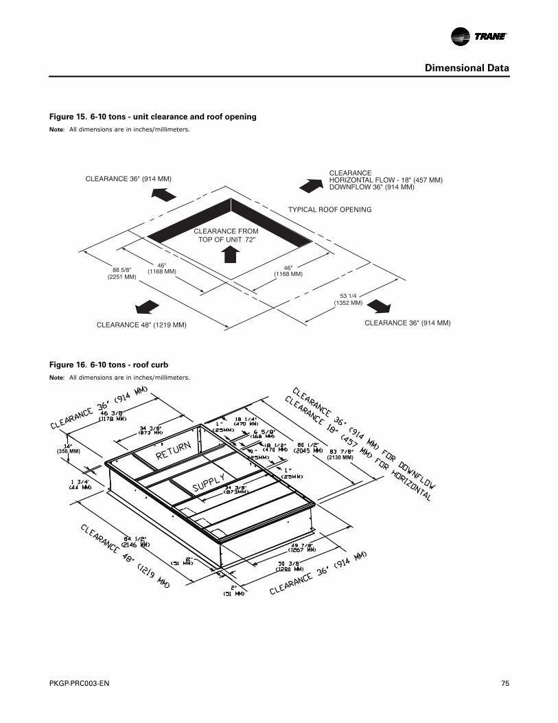
PKGP-PRC003-EN 75
Dimensional Data
Figure 15. 6-10 tons - unit clearance and roof opening
Note: All dimensions are in inches/millimeters.
Figure 16. 6-10 tons - roof curb
Note: All dimensions are in inches/millimeters.
(2130 MM)(356 MM)
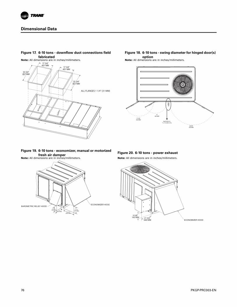
76 PKGP-PRC003-EN
Dimensional Data
Figure 17. 6-10 tons - downflow duct connections field
fabricated
Figure 18. 6-10 tons - swing diameter for hinged door(s)
optionNote: All dimensions are in inches/millimeters. Note: All dimensions are in inches/millimeters.
SUPP
LY
RETU
RN
ALL FLANGES 1 1/4" (31 MM)
857
857
21 3/8"543 MM
17"432 MM
34 5/8"879 MM
Applicable to Y_C models only
Figure 19. 6-10 tons - economizer, manual or motorized
fresh air damperFigure 20. 6-10 tons - power exhaust
Note: All dimensions are in inches/millimeters. Note: All dimensions are in inches/millimeters.
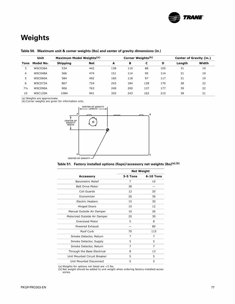
PKGP-PRC003-EN 77
Weights
Table 50. Maximum unit & corner weights (lbs) and center of gravity dimensions (in.)
Unit Maximum Model Weights(a) Corner Weights(b) Center of Gravity (in.)
Tons Model No. Shipping Net A B C D Length Width
3 WSC036A 534 442 138 110 88 105 31 19
4 WSC048A 566 474 151 114 95 114 31 19
5 WSC060A 584 492 160 118 97 117 31 19
6 WSC072A 867 724 243 184 128 170 38 22
7½ WSC090A 906 763 249 200 137 177 39 22
10 WSC120A 1084 941 320 243 162 215 38 21
(a) Weights are approximate.(b) Corner weights are given for information only.
Table 51. Factory installed options (fiops)/accessory net weights (lbs)(a),(b)
(a) Weights for options not listed are <5 lbs.(b) Net weight should be added to unit weight when ordering factory-installed acces-
sories.
Net Weight
Accessory 3-5 Tons 6-10 Tons
Barometric Relief 7 10
Belt Drive Motor 38 —
Coil Guards 12 20
Economizer 26 36
Electric Heaters 15 30
Hinged Doors 10 12
Manual Outside Air Damper 16 26
Motorized Outside Air Damper 20 30
Oversized Motor 5 8
Powered Exhaust — 80
Roof Curb 70 115
Smoke Detector, Return 7 7
Smoke Detector, Supply 5 5
Smoke Detector, Return 7 7
Through the Base Electrical 8 13
Unit Mounted Circuit Breaker 5 5
Unit Mounted Disconnect 5 5
78 PKGP-PRC003-EN
Mechanical Specifications
General
The units shall be convertible airflow. The operating range shall be between 115°F and 0°F in cooling as standard from the factory for units with microprocessor controls. Operating range for units with electromechanical controls shall be between 115°F and 40°F. Cooling performance shall be rated in accordance with ARI testing procedures. All units shall be factory assembled, internally wired, fully charged with R-22, and 100 percent run tested to check cooling operation, fan and blower rotation, and control sequence before leaving the factory. Wiring internal to the unit shall be colored and numbered for simplified identification. Units shall be UL listed and labeled, classified in accordance to UL 1995/CAN/CSA No. 236-M90 for Central Cooling Air Conditioners.
Casing
Unit casing shall be constructed of zinc coated, heavy gauge, galvanized steel. Exterior surfaces shall be cleaned, phosphatized, and finished with a weather-resistant baked enamel finish. Unit’s surface shall be tested 1000 hours in a salt spray test in compliance with ASTM B117. Cabinet construction shall allow for all maintenance on one side of the unit. Service panels shall have lifting handles and be removed and reinstalled by removing two fasteners while providing a water and air tight seal. All exposed vertical panels and top covers in the indoor air section shall be insulated with a cleanable foil-faced, fire-retardant permanent, odorless glass fiber material. The base of the unit shall be insulated with 1/8 inch, foil-faced, closed-cell insulation. All insulation edges shall be either captured or sealed. The unit’s base pan shall have no penetrations within the perimeter of the curb other than the raised 11/8 inch high downflow supply/return openings to provide an added water integrity precaution, if the condensate drain backs up. The base of the unit shall have provisions for forklift and crane lifting, with forklift capabilities on three sides of the unit.
Compressors
All 3 ton standard units shall have direct-drive, hermetic, reciprocating type compressors. The reciprocating type compressors have a centrifugal oil pump providing positive lubrication to moving parts. Motor shall be suction gas-cooled and shall have a voltage utilization range of plus or minus 10 percent of unit nameplate voltage. Crankcase heater, internal temperature, and current-sensitive motor overloads shall be included for maximum protection. Compressors shall have internal spring isolation and sound muffling to minimize vibration transmission and noise. Low pressure switches shall be standard.
3 ton high efficiency and 4-10 ton standard and high efficiency units shall have direct-drive, hermetic, scroll type compressors with centrifugal type oil pumps. Motor shall be suction gas-cooled and shall have a voltage utilization range of plus or minus 10 percent of unit nameplate voltage. Internal overloads shall be provided with the scroll compressors. Crankcase heaters shall be included on 7½ ton standard efficiency units.
Controls
Unit shall be completely factory-wired with necessary controls and contactor pressure lugs or terminal block for power wiring. Unit shall provide an external location for mounting a fused disconnect device. Microprocessor controls provide for all 24 volt control functions. The resident control algorithms shall make all heating, cooling, and/or ventilating decisions in response to electronic signals from sensors measuring indoor and outdoor temperatures. The control algorithm maintains accurate temperature control, minimizes drift from set point, and provides better building comfort. A centralized Microprocessor shall provide anti-short cycle timing and time delay between compressors to provide a higher level of machine protection.
Evaporator and Condenser Coils
Internally finned, 5/16” copper tubes mechanically bonded to a configured aluminum plate fin shall be standard. Coils shall be leak tested at the factory to ensure the pressure integrity. The evaporator coil and condenser coil shall be leak tested to 575 psig and pressure tested to 450 psig. The condenser coil shall have a patent pending 1+1+1 hybrid coil designed with slight gaps for ease of
PKGP-PRC003-EN 79
Mechanical Specifications
cleaning. A removable, reversible, double-sloped condensate drain pan with provision for through the base condensate drain is standard.
Filters
Throwaway filters shall be standard on all units. Optional 2-inch pleated filters shall also be available.
Indoor Fan
All 3-5 ton 3-phase units offer a choice of direct-drive, FC, centrifugal fans or belt driven, FC centrifugal fans with adjustable motor sheaves. 3-5 ton direct drive oversized motors shall be available for high static operations. All 6-10 ton units shall have belt drive motors with an adjustable idler-arm assembly for quick-adjustment to fan belts and motor sheaves. All motors shall be thermally protected. All indoor fan motors meet the U.S. Energy Policy Act of 1992 (EPACT).
Outdoor Fans
The outdoor fan shall be direct-drive, statically and dynamically balanced, draw-through in the vertical discharge position. The fan motor shall be permanently lubricated and shall have built-in thermal overload protection.
Phase Reversal Protection1
100% protection shall be standard for motors and compressors against problems caused by phase loss, phase imbalance and phase reversal indication.
Refrigerant Circuits
Each refrigerant circuit offers independent fixed orifice expansion devices. Service pressure ports, and refrigerant line filter driers are factory-installed as standard. An area shall be provided for replacement suction line driers.
Unit Top
The top cover shall be one piece construction or where seams exist, it shall be double-hemmed and gasket-sealed. The ribbed top adds extra strength and prevents water from pooling on unit top.
Factory Installed Options
Black Epoxy Pre-Coated Coils
The black epoxy coils have a thermoset vinyl coating that is bonded to the aluminum fin stock prior to the fin-stamping process. The pre-coated coils are an economical option for protection in mildly corrosive environments.
High Pressure Cutout
This is offered for units that do not have High Pressure cutout as standard. All 3-phase units with scroll compressors include High Pressure Cutout as standard.
Hinged Access Doors
Sheet metal hinges are available on the Filter/Evaporator, Supply Fan/Heat, and the Compressor/Control Access Doors.
Powered or Unpowered Convenience Outlet
This is a GFCI, 120v/15amp, 2 plug, convenience outlet, either powered or unpowered. When the convenience outlet is powered, a service receptacle disconnect will be available. The convenience outlet is powered from the line side of the disconnect or circuit breaker, and therefore will not be affected by the position of the disconnect or circuit breaker. This option can only be ordered when
1 3-5 ton units with Direct Drive Indoor Motor
80 PKGP-PRC003-EN
Mechanical Specifications
the Through the Base Electrical with either the Disconnect Switch or Circuit Breaker option is ordered.
Supply and/or Return Air Smoke Detector
With this option, if smoke is detected, all unit operation will be shut down. Reset will be manual at the unit. Return Air Smoke Detectors require minimum allowable airflow when used with certain models. See the Installation, Operation, and Maintenance (IOM) manual for the models affected and the minimum allowable airflow required. This option is available for microprocessor controlled units.
Through the Base Electrical Access
An electrical service entrance shall be provided allowing electrical access for both control and main power connections inside the curb and through the base of the unit. Option will allow for field installation of liquid-tight conduit and an external field-installed disconnect switch.
Through the Base Electrical with Circuit Breaker
This option is a thermal magnetic, molded case, HACR Circuit Breaker with provisions for through the base electrical connections. The circuit breaker will be installed in a water tight enclosure in the unit with access through a swinging door. Wiring will be provided from the switch to the unit high voltage terminal block. The circuit breaker will provide overcurrent protection, be sized per NEC and UL guidelines, and be agency recognized by UL/CSA.
Through the Base Electrical with Disconnect Switch
This 3-pole, molded case, disconnect switch with provisions for through the base electrical connections are available. The disconnect switch will be installed in the unit in a water tight enclosure with access through a swinging door. Wiring will be provided from the switch to the unit high voltage terminal block. The switch will be UL/CSA agency recognized. Note: The disconnect switch will be sized per NEC and UL guidelines but will not be used in place of unit overcurrent protection.
Two-Inch Pleated Filters
Two inch pleated media filters shall be available on all models.
Factory or Field Installed Options
Clogged Filter/Fan Failure Switch
A dedicated differential pressure switch is available to achieve active fan failure indication and/or clogged filter indication. These indications will be registered with either a zone sensor with status indication lights or an Integrated Comfort™ System. This option is available for microprocessor controlled units.
Differential Pressure Switches
These sensors allow individual fan failure and dirty filter indication for microprocessor controlled units. The fan failure switch will disable all unit functions and “flash” the Service LED on the zone sensor. The dirty filter switch will light the Service LED on the zone sensor and will allow continued unit operation.
Discharge Air Sensing
This option provides true discharge air sensing in heating models. This sensor is a status indicator readable through Tracer™ or Tracker™. This option is available for microprocessor controlled units.
Economizer
This accessory shall be available with or without barometric relief. The assembly includes fully modulating 0-100 percent motor and dampers, minimum position setting, preset linkage, wiring
PKGP-PRC003-EN 81
Mechanical Specifications
harness with plug, spring return actuator and fixed dry bulb control. The barometric relief shall provide a pressure operated damper that shall be gravity closing and shall prohibit entrance of outside air during the equipment “off” cycle. Optional solid state or differential enthalpy control shall be available for either factory or field installation. The economizer arrives in the shipping position and shall be moved to the operating position by the installing contractor.
Electric Heaters
Electric heat modules shall be available for installation within basic unit. Electric heater elements shall be constructed of heavy-duty nickel chromium elements internally delta connected for 240 volt, wye connected for 480 and 600 volt. Staging shall be achieved through ReliaTel™. Each heater package shall have automatically reset high limit control operating through heating element contactors. All heaters shall be individually fused from the factory, where required, and shall meet all NEC and CEC requirements when properly installed. Power assemblies shall provide single-point connection. Electric heat modules shall be UL listed or CSA certified.
Frostat
This option is to be utilized as a safety device. The Frostat opens when temperatures on the evaporator coil fall below 10°F. The temperature will need to rise to 50°F before closing. This option should be utilized in low airflow or high outside air applications.
LonTalk® Communication Interface
This option shall be provided to allow the unit to communicate as a Tracer™LCI-R device or directly with generic LonTalk Network Building Automation System Controls.
Oversized Motors
Direct drive oversized motors shall be available for high static applications.
Reference or Comparative Enthalpy
Reference Enthalpy is used to measure and communicate outdoor humidity. The unit receives and uses this information to provide improved comfort cooling while using the economizer. Comparative Enthalpy measures and communicates humidity for both outdoor and return air conditions, and return air temperature. The unit receives and uses this information to maximize use of economizer cooling, and to provide maximum occupant comfort control. Reference or Comparative Enthalpy option shall be available when a factory or field installed Downflow Economizer is ordered. This option is available on all downflow models.
Tool-less Hail Guards
Tool-less, hail protection quality coil guards are available for condenser coil protection.
Trane Communication Interface
This option shall be provided to interface ReliaTel™ controlled units with the Trane Integrated Comfort™ systems.
Field Installed Options
CO2 Sensing
The CO2 sensor shall have the ability to monitor space occupancy levels within the building by measuring the parts per million of CO2 (Carbon Dioxide) in the air. As the CO2 levels increase, the outside air damper modulates to meet the CO2 space ventilation requirements.
Dual Thermistor Remote Zone Sensor
This sensor will allow the customer to reduce the total number of remote sensors to obtain space temperature averaging. This sensor should be utilized with ReliaTel controls.
82 PKGP-PRC003-EN
Mechanical Specifications
High Static Drive
The high static drive option shall allow the standard motor on the 6 and 7½ ton to operate with improved external static capabilities.
Manual Outside Air Damper
This rain hood and screen shall provide up to 50 percent outside air.
Motorized Outside Air Damper
Manually set outdoor air dampers shall provide up to 50 percent outside air. Once set, outdoor air dampers shall open to set position when indoor fan starts. The damper shall close to the full closed position when indoor fan shuts down.
Powered Exhaust
The powered exhaust, available for 6-10 ton units, shall provide exhaust of return air, when using an economizer, to maintain better building pressurization.
Programmable Night Setback
Auto or manual changeover with seven-day programming. Keyboard selection of Heat, Cool, Fan, Auto, or On. All programmable sensors have System On, Heat, Cool, Service LED/indicators as standard. Night Setback Sensors have one (1) Occupied, one (1) Un-occupied, and one (1) Override program per day.
Remote Potentiometer
The minimum position setting of the economizer shall be adjusted with this accessory.
Roof Curb
The roof curb shall be designed to mate with the unit’s downflow supply and return and provide support and a water tight installation when installed properly. The roof curb design shall allow field-fabricated rectangular supply/return ductwork to be connected directly to the curb. Curb shall be shipped knocked down for field assembly and shall include wood nailer strips.
Thermostat
Two stage heating and cooling operation or one stage heating and cooling shall be available in either manual or automatic changeover. Automatic programmable electronic with night set back shall also be available.
Ventilation Override Accessory
With the Ventilation Override Accessory installed, the unit can be set to transition up to 3 different pre-programmed sequences for Smoke Purge, Pressurization, and Exhaust. The transition occurs when a binary input on the RTOM is closed (shorted). This would typically be a hard wired relay output from a smoke detector or fire control panel. The ventilation override accessory shall be available as field installed.
Zone Sensor
This control shall be provided to interface with the Micro equipped units and shall be available in either manual, automatic programmable with night setback, with system malfunction lights, or remote sensor options.

Literature Order Number PKGP-PRC003-EN
Date November 2008
Supersedes PKGP-PRC003-EN October 2008
Trane has a policy of continuous product and product data improvement and reserves the right to change design and specifications without notice.
www.trane.com
For more information, contact your local Trane office or e-mail us at [email protected]