Embed Size (px)
Citation preview
Bulletin 71.4D100163X012
February 2017
Type 1808
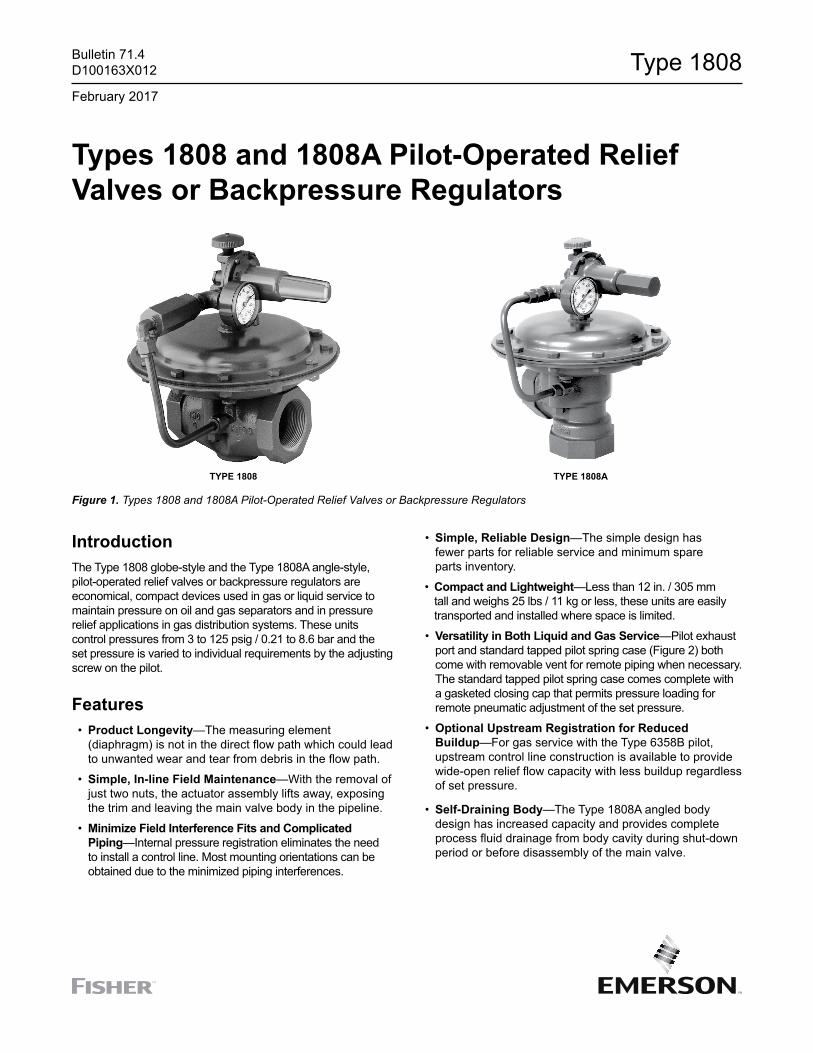
Types 1808 and 1808A Pilot-Operated Relief Valves or Backpressure Regulators
TyPe 1808 TyPe 1808A
Figure 1. Types 1808 and 1808A Pilot-Operated Relief Valves or Backpressure Regulators
IntroductionThe Type 1808 globe-style and the Type 1808A angle-style, pilot-operated relief valves or backpressure regulators are economical, compact devices used in gas or liquid service to maintain pressure on oil and gas separators and in pressure relief applications in gas distribution systems. These units control pressures from 3 to 125 psig / 0.21 to 8.6 bar and the set pressure is varied to individual requirements by the adjusting screw on the pilot.
Features • Product Longevity—The measuring element
(diaphragm) is not in the direct flow path which could lead to unwanted wear and tear from debris in the flow path.
• Simple, In-line Field Maintenance—With the removal of just two nuts, the actuator assembly lifts away, exposing the trim and leaving the main valve body in the pipeline.
• Minimize Field Interference Fits and Complicated Piping—Internal pressure registration eliminates the need to install a control line. Most mounting orientations can be obtained due to the minimized piping interferences.
• Simple, Reliable Design—The simple design has fewer parts for reliable service and minimum spare parts inventory.
• Compact and Lightweight—Less than 12 in. / 305 mm tall and weighs 25 lbs / 11 kg or less, these units are easily transported and installed where space is limited.
• Versatility in Both Liquid and Gas Service—Pilot exhaust port and standard tapped pilot spring case (Figure 2) both come with removable vent for remote piping when necessary. The standard tapped pilot spring case comes complete with a gasketed closing cap that permits pressure loading for remote pneumatic adjustment of the set pressure.
• Optional Upstream Registration for Reduced Buildup—For gas service with the Type 6358B pilot, upstream control line construction is available to provide wide-open relief flow capacity with less buildup regardless of set pressure.
• Self-Draining Body—The Type 1808A angled body design has increased capacity and provides complete process fluid drainage from body cavity during shut-down period or before disassembly of the main valve.
2
Type 1808
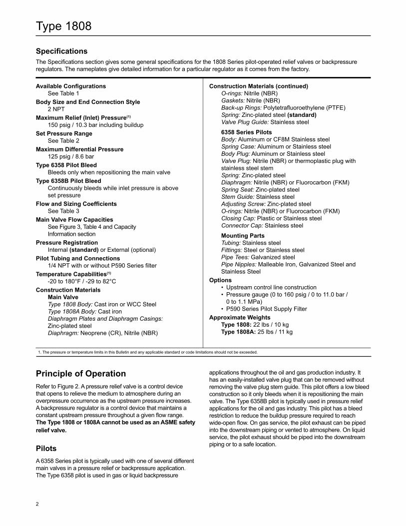
SpecificationsThe Specifications section gives some general specifications for the 1808 Series pilot-operated relief valves or backpressure regulators. The nameplates give detailed information for a particular regulator as it comes from the factory.
Available Configurations See Table 1Body Size and end Connection Style 2 NPT Maximum Relief (Inlet) Pressure(1)
150 psig / 10.3 bar including buildup Set Pressure Range See Table 2Maximum Differential Pressure 125 psig / 8.6 bar Type 6358 Pilot Bleed Bleeds only when repositioning the main valve Type 6358B Pilot Bleed Continuously bleeds while inlet pressure is above
set pressure Flow and Sizing Coefficients See Table 3Main Valve Flow Capacities See Figure 3, Table 4 and Capacity
Information sectionPressure Registration Internal (standard) or External (optional)Pilot Tubing and Connections 1/4 NPT with or without P590 Series filter Temperature Capabilities(1)
-20 to 180°F / -29 to 82°CConstruction Materials Main Valve Type 1808 Body: Cast iron or WCC Steel Type 1808A Body: Cast iron Diaphragm Plates and Diaphragm Casings:
Zinc-plated steel Diaphragm: Neoprene (CR), Nitrile (NBR)
Construction Materials (continued) O-rings: Nitrile (NBR) Gaskets: Nitrile (NBR) Back-up Rings: Polytetrafluoroethylene (PTFE) Spring: Zinc-plated steel (standard) Valve Plug Guide: Stainless steel
6358 Series Pilots Body: Aluminum or CF8M Stainless steel Spring Case: Aluminum or Stainless steel Body Plug: Aluminum or Stainless steel Valve Plug: Nitrile (NBR) or thermoplastic plug with
stainless steel stem Spring: Zinc-plated steel Diaphragm: Nitrile (NBR) or Fluorocarbon (FKM) Spring Seat: Zinc-plated steel Stem Guide: Stainless steel Adjusting Screw: Zinc-plated steel O-rings: Nitrile (NBR) or Fluorocarbon (FKM) Closing Cap: Plastic or Stainless steel Connector Cap: Stainless steel
Mounting Parts Tubing: Stainless steel Fittings: Steel or Stainless steel Pipe Tees: Galvanized steel Pipe Nipples: Malleable Iron, Galvanized Steel and
Stainless Steel Options • Upstream control line construction • Pressure gauge (0 to 160 psig / 0 to 11.0 bar /
0 to 1.1 MPa) • P590 Series Pilot Supply FilterApproximate Weights Type 1808: 22 lbs / 10 kg Type 1808A: 25 lbs / 11 kg
1. The pressure or temperature limits in this Bulletin and any applicable standard or code limitations should not be exceeded.
Principle of OperationRefer to Figure 2. A pressure relief valve is a control device that opens to relieve the medium to atmosphere during an overpressure occurrence as the upstream pressure increases. A backpressure regulator is a control device that maintains a constant upstream pressure throughout a given flow range. The Type 1808 or 1808A cannot be used as an ASMe safety relief valve.
PilotsA 6358 Series pilot is typically used with one of several different main valves in a pressure relief or backpressure application. The Type 6358 pilot is used in gas or liquid backpressure
applications throughout the oil and gas production industry. It has an easily-installed valve plug that can be removed without removing the valve plug stem guide. This pilot offers a low bleed construction so it only bleeds when it is repositioning the main valve. The Type 6358B pilot is typically used in pressure relief applications for the oil and gas industry. This pilot has a bleed restriction to reduce the buildup pressure required to reach wide-open flow. On gas service, the pilot exhaust can be piped into the downstream piping or vented to atmosphere. On liquid service, the pilot exhaust should be piped into the downstream piping or to a safe location.
3
Type 1808
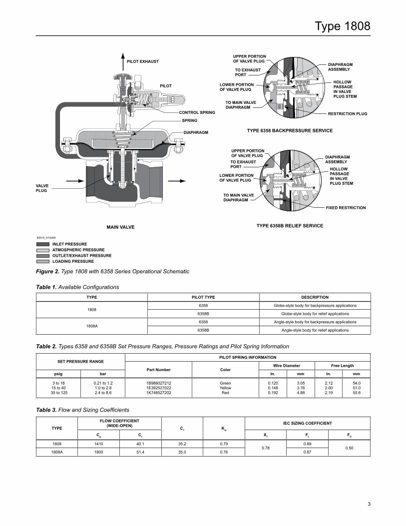
Figure 2. Type 1808 with 6358 Series Operational Schematic
TyPe 6358B ReLIeF SeRVICe
UPPeR PORTIOn OF VALVe PLUG
TO MAIn VALVe DIAPhRAGM
LOWeR PORTIOn OF VALVe PLUG
TO exhAUST PORT
FIxeD ReSTRICTIOn
DIAPhRAGM ASSeMBLy
hOLLOW PASSAGe In VALVe PLUG STeM
TyPe 6358 BACKPReSSURe SeRVICe
UPPeR PORTIOn OF VALVe PLUG
TO MAIn VALVe DIAPhRAGM
LOWeR PORTIOn OF VALVe PLUG
TO exhAUST PORT
ReSTRICTIOn PLUG
DIAPhRAGM ASSeMBLy
hOLLOW PASSAGe In VALVe PLUG STeM
E0075_07/2008
InLeT PReSSUReATMOSPheRIC PReSSUReOUTLeT/exhAUST PReSSUReLOADInG PReSSURe
MAIn VALVe
PILOT exhAUST
SPRInG
DIAPhRAGM
VALVe PLUG
COnTROL SPRInG
PILOT
Table 1. Available Configurations
TyPe PILOT TyPe DeSCRIPTIOn
18086358 Globe-style body for backpressure applications
6358B Globe-style body for relief applications
1808A6358 Angle-style body for backpressure applications
6358B Angle-style body for relief applications
Table 2. Types 6358 and 6358B Set Pressure Ranges, Pressure Ratings and Pilot Spring Information
SeT PReSSURe RAnGePILOT SPRInG InFORMATIOn
Part number ColorWire Diameter Free Length
psig bar In. mm In. mm
3 to 1815 to 40
35 to 125
0.21 to 1.21.0 to 2.82.4 to 8.6
1B9860272121E3925270221K748527202
GreenYellowRed
0.1200.1480.192
3.053.764.88
2.122.002.19
54.051.055.6
Table 3. Flow and Sizing Coefficients
TyPe
FLOW COeFFICIenT (WIDe-OPen) C1 Km
IeC SIZInG COeFFICIenT
Cg Cv xT FL FD
1808 1410 40.1 35.2 0.790.78
0.890.50
1808A 1800 51.4 35.0 0.76 0.87
4
Type 1808
Relief ValveAs long as the inlet pressure is below the set pressure, the pilot control spring keeps the pilot valve plug closed. Inlet pressure passes through the pilot restriction and registers as loading pressure on top of the diaphragm. Force from the main spring, in addition to inlet pressure bleeding through the pilot restriction, provide downward loading pressure to keep the main valve closed.
When the inlet pressure rises above the set pressure, the pressure on the pilot diaphragm overcomes the pilot control spring and opens the pilot valve plug. The pilot then exhausts the loading pressure from the top of the main valve diaphragm. The pilot continuously exhausts gas when the inlet pressure is above the set pressure. The inlet pressure unbalance overcomes the main spring force and opens the main valve.
As the inlet pressure drops, the pilot control spring begins to close the pilot valve plug and the exhaust slows. This causes the inlet pressure to build in the main valve diaphragm casing, allowing the control spring to close the main valve. Once the main valve is closed, the pilot valve plug closes and the exhaust stops.
Backpressure RegulatorAs long as inlet pressure remains below setpoint, the pilot spring keeps the pilot valve plug closed. Inlet pressure passes through the upper port around the upper portion of the valve plug then through the hollow passage in that valve plug. Force from the main spring, along with inlet pressure bleeding through the pilot, provide downward loading pressure to keep the main valve closed.
When inlet pressure rises above the set pressure, pressure on the pilot diaphragm overcomes the control spring to close the upper port and stroke the valve plug to open the lower port. The pilot then exhausts loading pressure from the top of the main valve diaphragm. The pilot exhausts only while repositioning the main valve. The inlet pressure unbalance overcomes the spring force and opens the main valve.
As the inlet pressure drops, the pilot control spring begins to close the pilot valve plug and the exhaust slows. This causes the inlet pressure to build in the main valve diaphragm casing, allowing the control spring to close the main valve. Once the main valve is closed, the pilot valve plug closes and the exhaust stops.
InstallationTypes 1808 and 1808A relief valves or backpressure regulators may be installed in any position as long as the flow through the main valve corresponds with the flow arrow on the main valve body (Type 1808) or runs in through the bottom connection and out through the side connection (Type 1808A).
An upstream control line is not required because of the integral pilot supply tubing; however, for a more accurate
relief valve or backpressure regulator, this tubing may be disconnected for upstream registration and the main valve diaphragm casing tapping plugged. For liquid service, the pilot exhaust should be piped to the downstream line or to a safe location. For gas service, the pilot must be piped to a safe area because, in enclosed conditions such as inside installations, exhausting gas can accumulate causing a danger of explosion. A vent line or stack must be located to avoid venting gas near buildings, air intakes or other hazardous locations and the line or stack opening must be protected against anything that might clog it. The thrust effect of a venting relief valve must be considered when designing relief valve outlet piping and anchoring.
Capacity Information
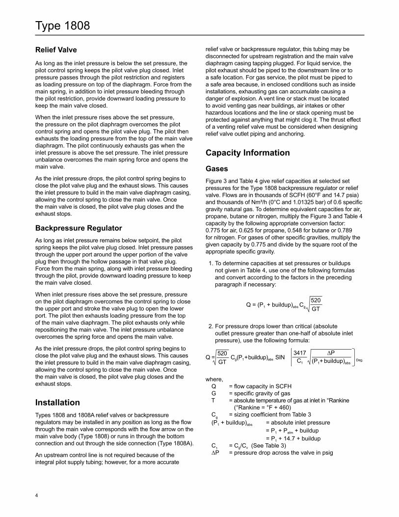
GasesFigure 3 and Table 4 give relief capacities at selected set pressures for the Type 1808 backpressure regulator or relief valve. Flows are in thousands of SCFh (60°F and 14.7 psia) and thousands of Nm³/h (0°C and 1.01325 bar) of 0.6 specific gravity natural gas. To determine equivalent capacities for air, propane, butane or nitrogen, multiply the Figure 3 and Table 4 capacity by the following appropriate conversion factor: 0.775 for air, 0.625 for propane, 0.548 for butane or 0.789 for nitrogen. For gases of other specific gravities, multiply the given capacity by 0.775 and divide by the square root of the appropriate specific gravity.
1. To determine capacities at set pressures or buildups not given in Table 4, use one of the following formulas and convert according to the factors in the preceding paragraph if necessary:
Q = (P1 + buildup)abs Cg
520GT
2. For pressure drops lower than critical (absolute outlet pressure greater than one-half of absolute inlet pressure), use the following formula:
Q = Cg(P1 + buildup)abs SIN Deg.
520GT
ΔP(P1 + buildup)abs
3417C1
where, Q = flow capacity in SCFh G = specific gravity of gas T = absolute temperature of gas at inlet in °Rankine (°Rankine = °F + 460) Cg = sizing coefficient from Table 3 (P1 + buildup)abs = absolute inlet pressure = P1 + Patm + buildup = P1 + 14.7 + buildup C1 = Cg/Cv (See Table 3) ΔP = pressure drop across the valve in psig
5
Type 1808
Figure 3b. Capacities for the Type 1808A Using Standard Internal Control Line and a Type 6358 or 6358B Pilot with High-Gain Restriction
Note: Capacities based on 0 psig / 0 bar outlet pressure. If outlet pressure is not 0 psig / 0 bar, shaded capacities may be recalculated using the wide-open Cg and the desired pressure drop.
Figure 3a. Capacities for the Type 1808 Using Standard Internal Control Line and a Type 6358 or 6358B Pilot with High-Gain Restriction
Figure 3c. Capacities for the Type 1808 Using Standard Internal Control Line and a Type 6358 or 6358B Pilot with High-Gain Restriction
Figure 3d. Capacities for the Type 1808A Using a Standard Internal Control Line and a Type 6358 or 6358B Pilot with High-Gain Restriction
0
5
10
15
2015 psig / 1 bar setpoint
10 psig / 0.69 bar setpoint
5 psig / 0.34 bar setpoint
3 psig / 0.21 bar setpoint
25
Ups
trea
m P
ress
ure,
psi
g
Flow Rate (SCFH at 0.06 SG Natural Gas)
TYPE 1808 GREEN CONTROL SPRING (1B986027212) 3 TO 18 psig / 0.21 TO 1.24 bar SET PRESSURE RANGE
30
10,000 20,000 30,000 40,000 50,000 60,000 70,000 0
5
10
15
20
25
30
10,000 20,000 30,000 40,000 50,000 60,000 70,000 80,000 90,000
Flow Rate (SCFH at 0.06 SG Natural Gas)
TYPE 1808A GREEN CONTROL SPRING (1B986027212) 3 TO 18 psig / 0.21 TO 1.24 bar SET PRESSURE RANGE
Ups
trea
m P
ress
ure,
psi
g
15 psig / 1 bar setpoint
10 psig / 0.69 bar setpoint
5 psig / 0.34 bar setpoint
3 psig / 0.21 bar setpoint0
5
10
15
20
25
30
10,000 20,000 30,000 40,000 50,000 60,000 70,000 80,000 90,000
Flow Rate (SCFH at 0.06 SG Natural Gas)
TYPE 1808A GREEN CONTROL SPRING (1B986027212) 3 TO 18 psig / 0.21 TO 1.24 bar SET PRESSURE RANGE
Ups
trea
m P
ress
ure,
psi
g
15 psig / 1 bar setpoint
10 psig / 0.69 bar setpoint
5 psig / 0.34 bar setpoint
3 psig / 0.21 bar setpoint
0 10,000 20,000 30,000 40,000 50,000 60,000 70,000 80,000 90,000 100,000 110,000 120,000 130,000 140,000 150,000
10
20
30
40
50
60
70
TYPE 1808YELLOW CONTROL SPRING (1E392527022) 15 TO 40 psig / 1 TO 2.8 bar SET PRESSURE RANGE
Flow Rate (SCFH at 0.06 SG Natural Gas)
Ups
trea
m P
ress
ure,
psi
g
40 psig / 2.8 bar setpoint
30 psig / 2.1 bar setpoint
20 psig / 1.4 bar setpoint
15 psig / 1.0 bar setpoint
0 25,000 50,000 75,000 100,000 125,000 150,000 175,000
10
20
30
40
50
60
70
Ups
trea
m P
ress
ure,
psi
g
Flow Rate (SCFH at 0.06 SG Natural Gas)
TYPE 1808A YELLOW CONTROL SPRING (1E392527022) 15 TO 40 psig / 1 TO 2.8 bar SET PRESSURE RANGE
40 psig / 2.8 bar setpoint
30 psig / 2.1 bar setpoint
20 psig / 1.4 bar setpoint
15 psig / 1.0 bar setpoint
6
Type 1808
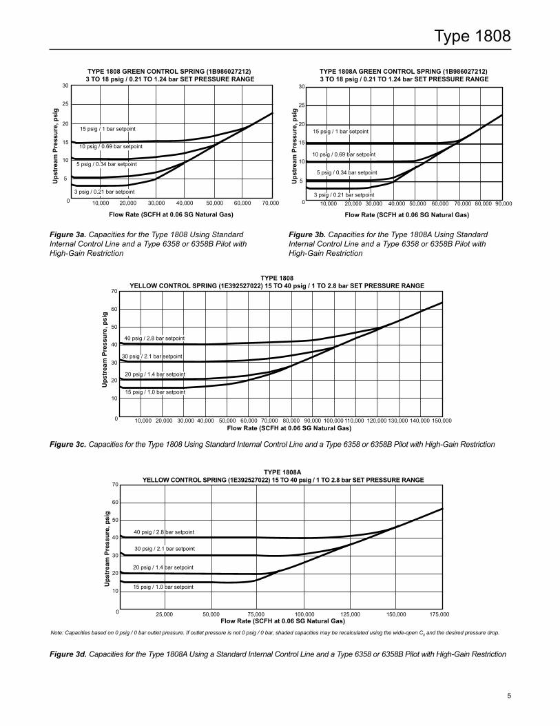
Figure 3e. Capacities for the Type 1808 Using Standard Internal Control Line and a Type 6358 or 6358B Pilot with High-Gain Restriction
Note: Capacities based on 0 psig / 0 bar outlet pressure. If outlet pressure is not 0 psig / 0 bar, shaded capacities may be recalculated using the wide-open Cg and the desired pressure drop.
Figure 3f. Capacities for the Type 1808A Using Standard Internal Control Line and a Type 6358 or 6358B Pilot with High-Gain Restriction
Note: Capacities based on 0 psig / 0 bar outlet pressure. If outlet pressure is not 0 psig / 0 bar, shaded capacities may be recalculated using the wide-open Cg and the desired pressure drop.
0 50,000 100,000 150,000 200,000 250,000 300,000 350,000 400,000
20
40
60
80
100
120
140
Ups
trea
m P
ress
ure,
psi
g
Flow Rate (SCFH at 0.06 SG Natural Gas)
TYPE 1808ARED CONTROL SPRING (1K748527202) 35 TO 125 psig / 2.4 TO 8.6 bar SET PRESSURE RANGE
125 psig / 8.6 bar setpoint
110 psig / 7.6 bar setpoint
100 psig / 6.9 bar setpoint
90 psig / 6.2 bar setpoint
80 psig / 5.5 bar setpoint
70 psig / 4.8 bar setpoint
60 psig / 4.1 bar setpoint
50 psig / 3.4 bar setpoint
40 psig / 2.8 bar setpoint
0 50,000 100,000 150,000 200,000 250,000 300,000 320,000
20
40
60
80
100
120
140
Ups
trea
m P
ress
ure,
psi
g
Flow Rate (SCFH at 0.06 SG Natural Gas)
TYPE 1808RED CONTROL SPRING (1K74857202) 35 TO 125 psig / 2.4 TO 8.6 bar SET PRESSURE RANGE
125 psig / 8.6 bar setpoint
110 psig / 7.6 bar setpoint
100 psig / 6.9 bar setpoint
90 psig / 6.2 bar setpoint
80 psig / 5.5 bar setpoint
70 psig / 4.8 bar setpoint
60 psig / 4.1 bar setpoint
50 psig / 3.4 bar setpoint
40 psig / 2.8 bar setpoint
7
Type 1808
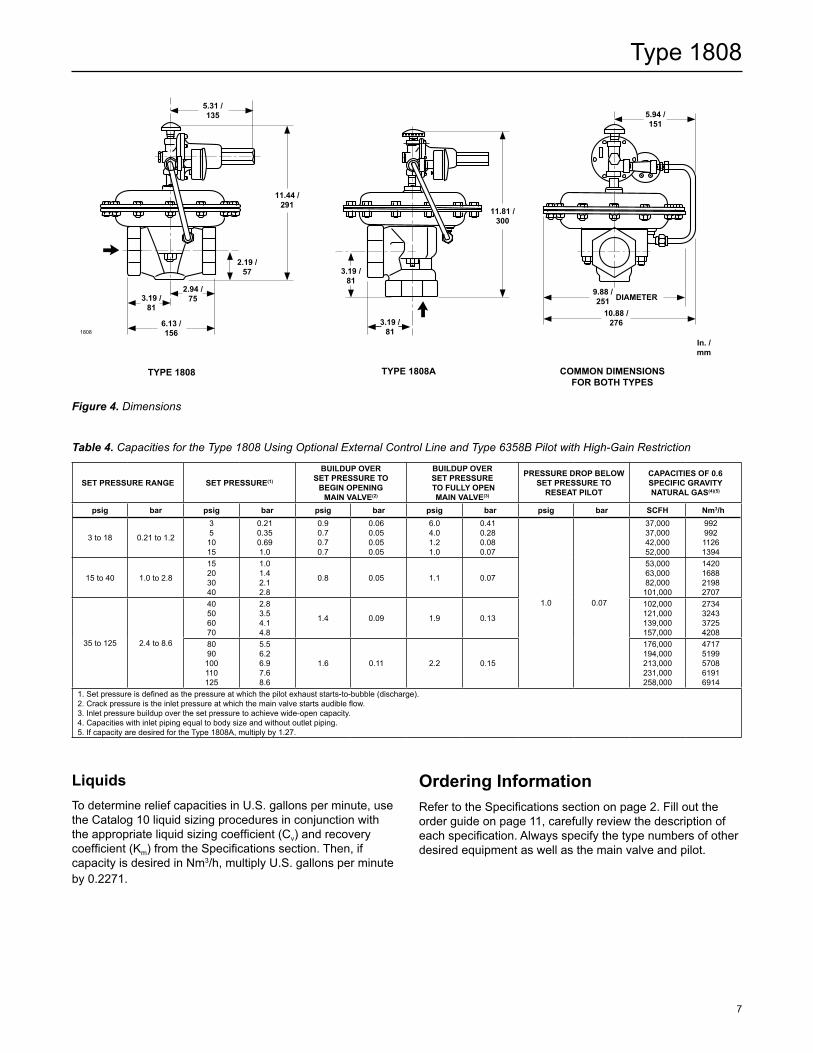
5.31 /135
11.44 /291
2.19 /57
2.94 /75
6.13 /156
3.19 /81
11.81 /300
3.19 /81
3.19 /81
5.94 /151
9.88 /251 DIAMeTeR
10.88 /276
TyPe 1808 TyPe 1808A COMMOn DIMenSIOnS FOR BOTh TyPeS
Figure 4. Dimensions
1808
In. / mm
Liquids To determine relief capacities in U.S. gallons per minute, use the Catalog 10 liquid sizing procedures in conjunction with the appropriate liquid sizing coefficient (Cv) and recovery coefficient (Km) from the Specifications section. Then, if capacity is desired in Nm3/h, multiply U.S. gallons per minute by 0.2271.
Ordering Information Refer to the Specifications section on page 2. Fill out the order guide on page 11, carefully review the description of each specification. Always specify the type numbers of other desired equipment as well as the main valve and pilot.
Table 4. Capacities for the Type 1808 Using Optional External Control Line and Type 6358B Pilot with High-Gain Restriction
SeT PReSSURe RAnGe SeT PReSSURe(1)
BUILDUP OVeR SeT PReSSURe TO
BeGIn OPenInG MAIn VALVe(2)
BUILDUP OVeR SeT PReSSURe TO FULLy OPen
MAIn VALVe(3)
PReSSURe DROP BeLOW SeT PReSSURe TO
ReSeAT PILOT
CAPACITIeS OF 0.6 SPeCIFIC GRAVITy nATURAL GAS(4)(5)
psig bar psig bar psig bar psig bar psig bar SCFh nm3/h
3 to 18 0.21 to 1.2
351015
0.21 0.350.691.0
0.90.70.70.7
0.060.050.050.05
6.04.01.21.0
0.410.280.080.07
1.0 0.07
37,00037,00042,00052,000
99299211261394
15 to 40 1.0 to 2.8
15203040
1.01.42.12.8
0.8 0.05 1.1 0.07
53,00063,00082,000101,000
1420168821982707
35 to 125 2.4 to 8.6
40506070
2.83.54.14.8
1.4 0.09 1.9 0.13
102,000121,000139,000157,000
2734324337254208
8090100110125
5.56.26.97.68.6
1.6 0.11 2.2 0.15
176,000194,000213,000231,000258,000
47175199570861916914
1. Set pressure is defined as the pressure at which the pilot exhaust starts-to-bubble (discharge).2. Crack pressure is the inlet pressure at which the main valve starts audible flow.3. Inlet pressure buildup over the set pressure to achieve wide-open capacity.4. Capacities with inlet piping equal to body size and without outlet piping.5. If capacity are desired for the Type 1808A, multiply by 1.27.
Type 1808
Facebook.com/EmersonAutomationSolutions
LinkedIn.com/company/emerson-automation-solutions
Twitter.com/emr_automation
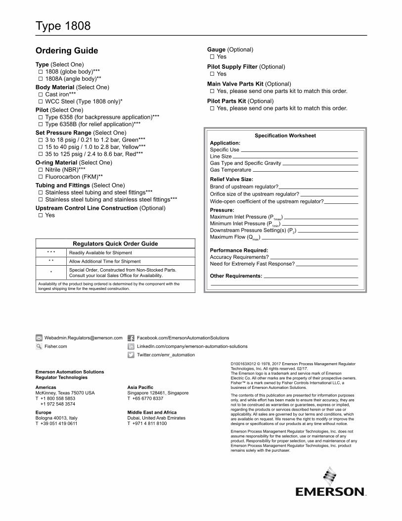
Regulators Quick Order Guide* * * Readily Available for Shipment
* * Allow Additional Time for Shipment
* Special Order, Constructed from Non-Stocked Parts. Consult your local Sales Office for Availability.
Availability of the product being ordered is determined by the component with the longest shipping time for the requested construction.
Specification Worksheet Application: Specific Use Line Size Gas Type and Specific Gravity Gas Temperature
Relief Valve Size: Brand of upstream regulator? Orifice size of the upstream regulator? Wide-open coefficient of the upstream regulator? Pressure: Maximum Inlet Pressure (P1max) Minimum Inlet Pressure (P1min) Downstream Pressure Setting(s) (P2) Maximum Flow (Qmax)
Performance Required: Accuracy Requirements? Need for Extremely Fast Response?
Other Requirements:
Ordering GuideType (Select One) 1808 (globe body)*** 1808A (angle body)**Body Material (Select One) Cast iron*** WCC Steel (Type 1808 only)*Pilot (Select One) Type 6358 (for backpressure application)*** Type 6358B (for relief application)***Set Pressure Range (Select One) 3 to 18 psig / 0.21 to 1.2 bar, Green*** 15 to 40 psig / 1.0 to 2.8 bar, Yellow*** 35 to 125 psig / 2.4 to 8.6 bar, Red***O-ring Material (Select One) Nitrile (NBR)*** Fluorocarbon (FKM)**Tubing and Fittings (Select One) Stainless steel tubing and steel fittings*** Stainless steel tubing and stainless steel fittings***Upstream Control Line Construction (Optional) Yes
Gauge (Optional) Yes
Pilot Supply Filter (Optional) Yes
Main Valve Parts Kit (Optional) Yes, please send one parts kit to match this order.
Pilot Parts Kit (Optional) Yes, please send one parts kit to match this order.
Fisher.com
D100163X012 © 1978, 2017 Emerson Process Management Regulator Technologies, Inc. All rights reserved. 02/17. The Emerson logo is a trademark and service mark of Emerson Electric Co. All other marks are the property of their prospective owners. Fisher™ is a mark owned by Fisher Controls International LLC, a business of Emerson Automation Solutions.
The contents of this publication are presented for information purposes only, and while effort has been made to ensure their accuracy, they are not to be construed as warranties or guarantees, express or implied, regarding the products or services described herein or their use or applicability. All sales are governed by our terms and conditions, which are available on request. We reserve the right to modify or improve the designs or specifications of our products at any time without notice.
Emerson Process Management Regulator Technologies, Inc. does not assume responsibility for the selection, use or maintenance of any product. Responsibility for proper selection, use and maintenance of any Emerson Process Management Regulator Technologies, Inc. product remains solely with the purchaser.
Emerson Automation Solutions Regulator Technologies
Americas McKinney, Texas 75070 USA T +1 800 558 5853
+1 972 548 3574
Europe Bologna 40013, Italy T +39 051 419 0611
Asia Pacific Singapore 128461, Singapore T +65 6770 8337
Middle East and Africa Dubai, United Arab Emirates T +971 4 811 8100