Embed Size (px)
Citation preview

PIC32&Overview&
E155&
2
Outline
PIC32 Architecture MIPS M4K Core PIC32 Peripherals PIC32 Basic Operations Clock

Approximately $16B of microcontrollers were sold in 2011, and the market continues to grow by about 10% a year.
Microcontrollers have become ubiquitious and nearly invisible, with an estimated 150 in each home and 50 in each automobile in 2010.
The 8051 is a classic 8-bit microcontroller originally developed by Intel in 1980 and now sold by a host of manufacturers.
Microchip’s PIC16 and PIC18-series are 8-bit market leaders. PIC(Peripheral Interface Controller)
Microcontroller
3

The Atmel AVR series of microcontrollers has been popularized among hobbyists as the brain of the Arduino platform.
Among 32-bit microcontrollers, Renesas leads the overall market, while ARM is a major player in mobile systems including the iPhone. Freescale, Samsung, Texas Instruments, and Infineon are other major microcontroller manufacturers.
Focus on the PIC32MX675F512H, a member of Microchip’s PIC32-series of microcontrollers based on the 32-bit MIPS microprocessor.
Microcontroller
4
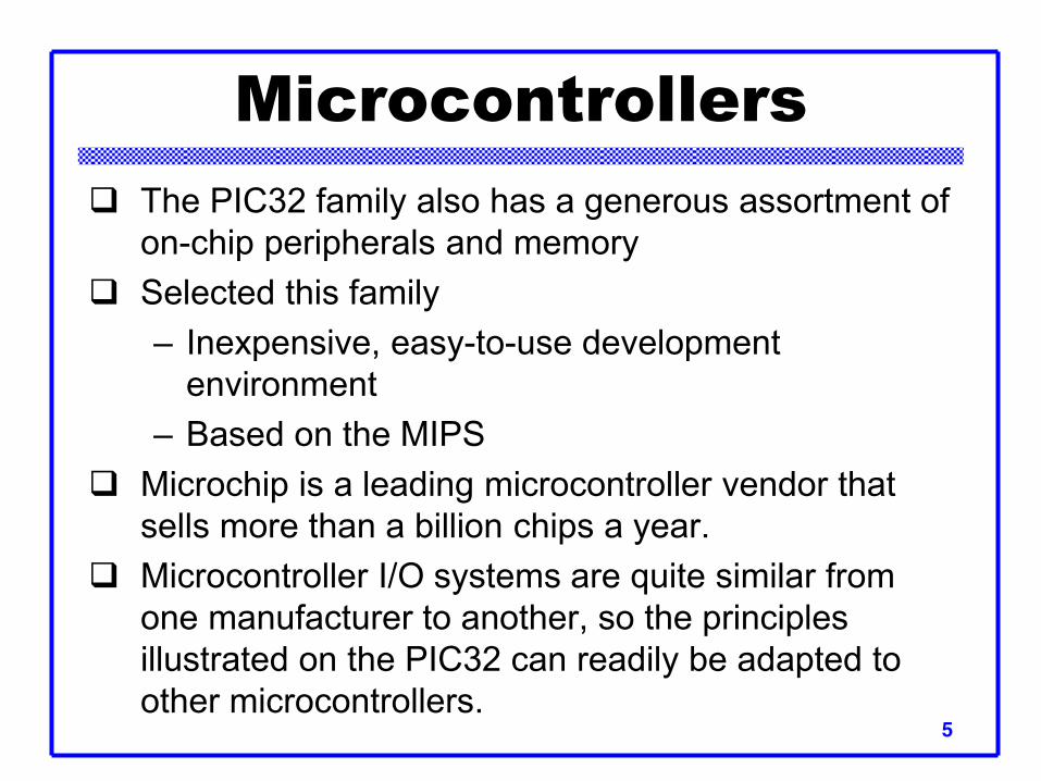
The PIC32 family also has a generous assortment of on-chip peripherals and memory
Selected this family – Inexpensive, easy-to-use development
environment – Based on the MIPS
Microchip is a leading microcontroller vendor that sells more than a billion chips a year.
Microcontroller I/O systems are quite similar from one manufacturer to another, so the principles illustrated on the PIC32 can readily be adapted to other microcontrollers.
Microcontrollers
5
3
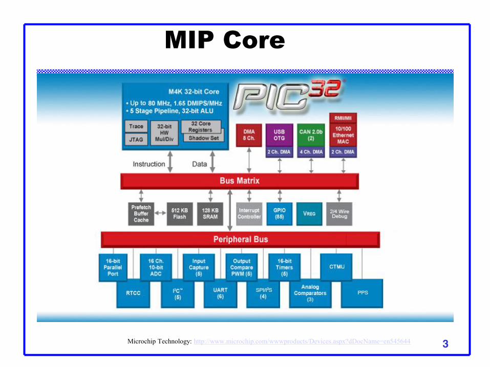
MIP Core
Microchip Technology: http://www.microchip.com/wwwproducts/Devices.aspx?dDocName=en545644

3
MIP Core
Microchip Technology: http://www.microchip.com/wwwproducts/Devices.aspx?dDocName=en545644
4
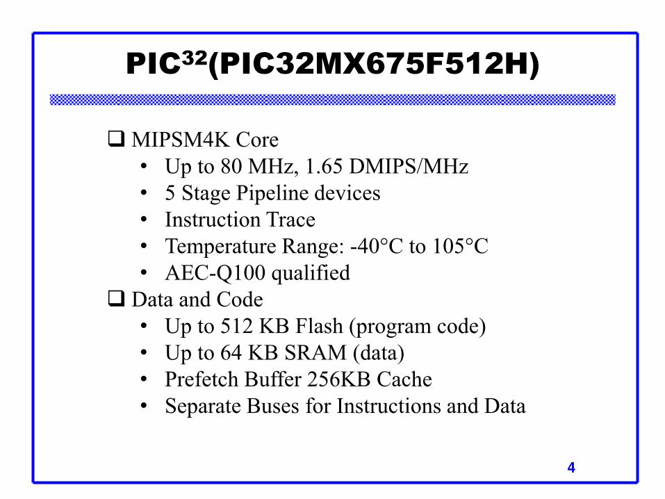
PIC32(PIC32MX675F512H)
MIPSM4K Core • Up to 80 MHz, 1.65 DMIPS/MHz • 5 Stage Pipeline devices • Instruction Trace • Temperature Range: -40°C to 105°C • AEC-Q100 qualified
Data and Code • Up to 512 KB Flash (program code) • Up to 64 KB SRAM (data) • Prefetch Buffer 256KB Cache • Separate Buses for Instructions and Data

4
PIC32 Peripheral Interconnect
Connected Peripherals with DMA • Full-speed USB Host/Device/OTG • 10/100 Ethernet MAC with MII/RMII
Interfaces • 2x CAN 2.0B Ports • Up to 6 UART, 4 I²C™, 3 SPI Ports, CTMU
and I S • Up to 8 Additional Channels of General
Purpose DMA

PIC32 Peripheral Features
6-<10>
Parameter Name Value Family PIC32MX6xx Max Speed MHz 80 Program Memory Size (KB) 512 RAM (KB) 64 Temperature Range (C) -40 to 105 Operating Voltage Range (V) 2.3 to 3.6 DMA Channels 8 SPITM 3 I2CTM Compatible 4 CTMU NO USB (Channels, Speed, Compliance 1,FS Host/OTG,USB 2.0
OTG A/D channels 16 Max A/D Sample Rate (KSPS) 1000 Input Capture 5 Output Compare/Std. PWM 5 16-bit Digital Timers 5 Parallel Port PMP Comparators 2 Internal Oscillator 8 MHz, 32 kHz RTCC Yes I/O Pins 53 Pin Count 64
Microchip Technology: http://www.microchip.com/wwwproducts/Devices.aspx?dDocName=en545644

PIC32 Virtual Memory Map
6-<11>

PIC32 PinOut and Package
6
PIC32MX6xxFxxH pinout. Black pins are 5 V-tolerant
PIC32 in 64-pin TQFP package
Microchip Technology: http://www.microchip.com/wwwproducts/Devices.aspx?dDocName=en545644

PIC Basic Operation
14
3.3 V
MCLR 7
CLKI 31
10 F
PGEC1 15
PGED1 16
LTC1117-3.3GN
D
Vout
Vin
4.5-12 V
10 F
PIC
32
10 F
10 VD
D
0.1F
Bypass Capacitors
Voltage Regulator
3.3 V
Reset Switch
3.3 V
VDD 4
OUT 3
1 OE
2 GND0.1 F
9 GN
D
3.3 V3.3 V
26 VD
D
0.1F
25 GN
D
3.3 V
38 VD
D
0.1F
41 GN
D
3.3 V
57 VD
D
0.1F
19 AV
DD
0.1F
20 AG
ND
3.3 V
56 VC
OR
E
RJ11 ICD3 Jack
1 VPP/MCLR
SG636PCE 40 MHz Oscillator
2 VDD
3 GND
4 PGD
5 PGC
6 LVP
3.3 V
10k

PIC Basic Operation
15
• Program the microcontroller is with a Microchip In Circuit Debugger (ICD) 3, or a puck.
• Communicate with the PIC32 from a PC to download code and to debug the program.
• Connects to a USB port on the PC and to a six-pin RJ-11 modular connector (US telephone jacks) on the PIC32 development board.
• The ICD3 communicates with the PIC over a 2-wire In-Circuit Serial Programming interface with a clock and a bidirectional data pin.
• Programming by using Microchip’s free MPLAB Integrated Development Environment (IDE) to write your programs in assembly language or C, debug them in simulation, and download and test them on a development board by means of the ICD.
Microchip ICD3

Timers
16
5 timers: Timer1 (Type A) Timers 2/3, Timers4/5 (TypeB) 16-bit timer/counter
Common features: Software-selectable internal or external clock source Programmable interrupt generation and priority Gated external pulse counter
Microchip Technology: http://ww1.microchip.com/downloads/en/DeviceDoc/61156G.pdf

Type A: - Asynchronous timer/counter with a built-in oscillator - Operational during CPU Sleep mode - Software selectable prescalers 1:1, 1:8, 1:64 and 1:256
Type B: - Ability to form a 32-bit timer/counter - Software prescalers 1:1, 1:2, 1:4, 1:8, 1:16, 1:32, 1:64 and 1:256 - Event trigger capability
Timers
17 Microchip Technology: http://www.microchip.com/wwwproducts/Devices.aspx?dDocName=en545644

Type B Timer Block Diagram
18 Microchip Technology: http://www.microchip.com/wwwproducts/Devices.aspx?dDocName=en545644

Timer Registers
19
•TxCON: 16-bit control register associated with the timer •TMRx: 16-bit timer count register •PRx: 16-bit register associated with the timer
Microchip Technology: http://www.microchip.com/wwwproducts/Devices.aspx?dDocName=en545644

Timer1 Register
20 Microchip Technology: http://www.microchip.com/wwwproducts/Devices.aspx?dDocName=en545644

bit 31-16 Reserved: Write ‘0’;; ignore read bit 15 ON: Timer On bit(1)
– 1 = Timer is enabled – 0 = Timer is disabled
bit 14 FRZ: Freeze in Debug Exception Mode bit(2) – 1 = Freeze operation when CPU is in Debug Exception mode – 0 = Continue operation even when CPU is in Debug Exception mode – bit 13 SIDL: Stop in Idle Mode bit – 1 = Discontinue operation when device enters Idle mode – 0 = Continue operation even in Idle mode
bit 12 TWDIS: Asynchronous Timer Write Disable bit – 1 = Writes to TMR1 are ignored until pending write operation completes – 0 = Back-to-back writes are enabled (Legacy Asynchronous Timer functionality)
bit 11 TWIP: Asynchronous Timer Write in Progress bit – In Asynchronous Timer mode: – 1 = Asynchronous write to TMR1 register in progress – 0 = Asynchronous write to TMR1 register complete – In Synchronous Timer mode: – This bit is read as ‘0’. – bit 10-8 Reserved: Write ‘0’;; ignore read
Note 1: When using 1:1 PBCLK divisor, the user’s software should not read/write the peripheral SFRs in the SYSCLK cycle immediately following the instruction that clears the module’s ON bit. 2: This bit is writable only in Debug Exception mode. It is forced to ‘0’ in normal mode.
Timer1 Control Registers
21

bit 7 TGATE: Timer Gated Time Accumulation Enable bit – When TCS = 1: – This bit is ignored and is read as ‘0’. – When TCS = 0: – 1 = Gated time accumulation is enabled – 0 = Gated time accumulation is disabled
bit 6 Reserved: Write ‘0’;; ignore read bit 5-4 TCKPS<1:0>: Timer Input Clock Prescale Select bits
– 11 = 1:256 prescale value – 10 = 1:64 prescale value – 01 = 1:8 prescale value – 00 = 1:1 prescale value
bit 3 Reserved: Write ‘0’;; ignore read bit 2 TSYNC: Timer External Clock Input Synchronization Selection bit
– When TCS = 1: – 1 = External clock input is synchronized – 0 = External clock input is not synchronized – When TCS = 0: – This bit is ignored and is read as ‘0’.
bit 1 TCS: Timer Clock Source Select bit – 1 = External clock from TxCKI pin – 0 = Internal peripheral clock
bit 0 Reserved: Write ‘0’;; ignore read Note 1: When using 1:1 PBCLK divisor, the user’s software should not read/write the peripheral SFRs in the SYSCLK cycle immediately following the instruction that clears the module’s ON bit. 2: This bit is writable only in Debug Exception mode. It is forced to ‘0’ in normal mode.
Timer 1 Control Registers
22
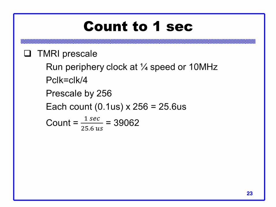
Count to 1 sec
23
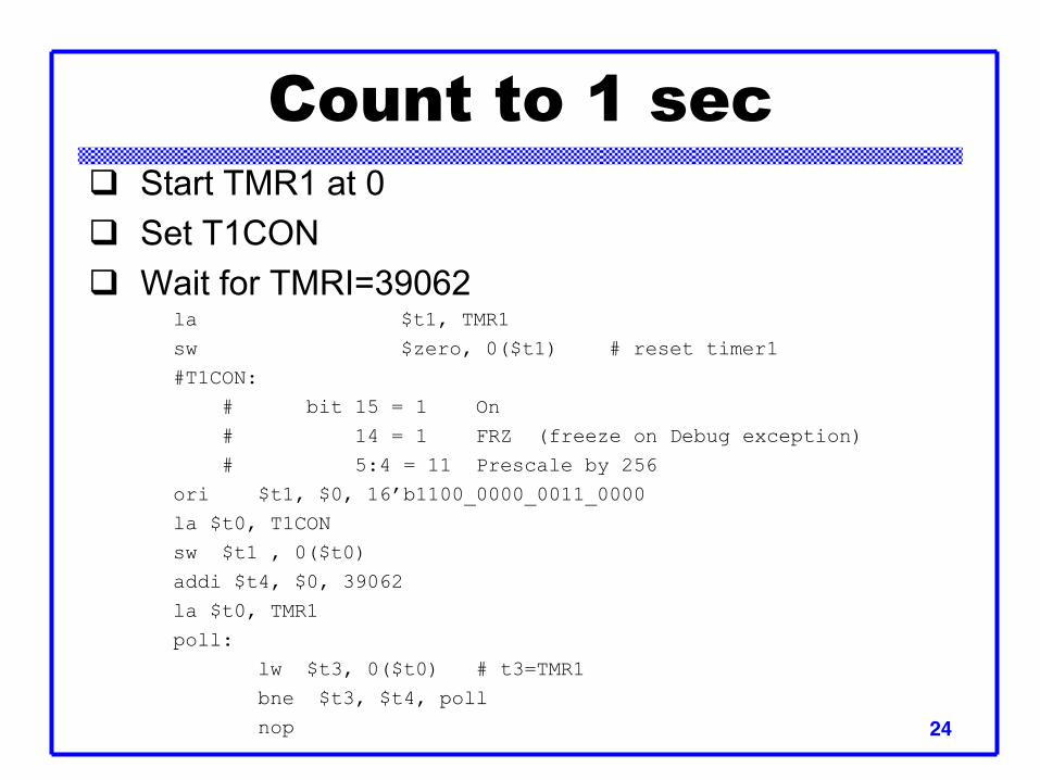
Start TMR1 at 0 Set T1CON Wait for TMRI=39062 la $t1, TMR1 sw $zero, 0($t1) # reset timer1
#T1CON: # bit 15 = 1 On # 14 = 1 FRZ (freeze on Debug exception) # 5:4 = 11 Prescale by 256 ori $t1, $0, 16’b1100_0000_0011_0000 la $t0, T1CON sw $t1 , 0($t0) addi $t4, $0, 39062 la $t0, TMR1 poll: lw $t3, 0($t0) # t3=TMR1 bne $t3, $t4, poll nop
Count to 1 sec
24