Embed Size (px)
Citation preview
PIAGGIO WOULD LIKE TO THANK YOU
for choosing one of its products. We have prepared this manual to help you to get the very best from your scooter. Please read it carefully before ridingthe scooter for the first time. It contains information, tips and precautions for using your scooter. It also describes features, details and devices to assureyou that you have made the right choice. We believe that if you follow our suggestions, you will soon get to know your new vehicle and it will serve youwell for a long time to come. This booklet forms an integral part of the scooter; should the scooter be sold, it must be transferred to the new owner.
MP3 250 i.e.
The instructions given in this manual are intended to provide a clear, simple guide to using your scooter; this booklet also details routine maintenanceprocedures and regular checks that should be carried out on the vehicle at an authorised Dealer or Service Centre. The booklet also containsinstructions for simple repairs. Any operations not specifically described in this manual require the use of special tools and/or particular technicalknowledge: to carry out these operations refer to any authorised Dealer of Service Centres.
2
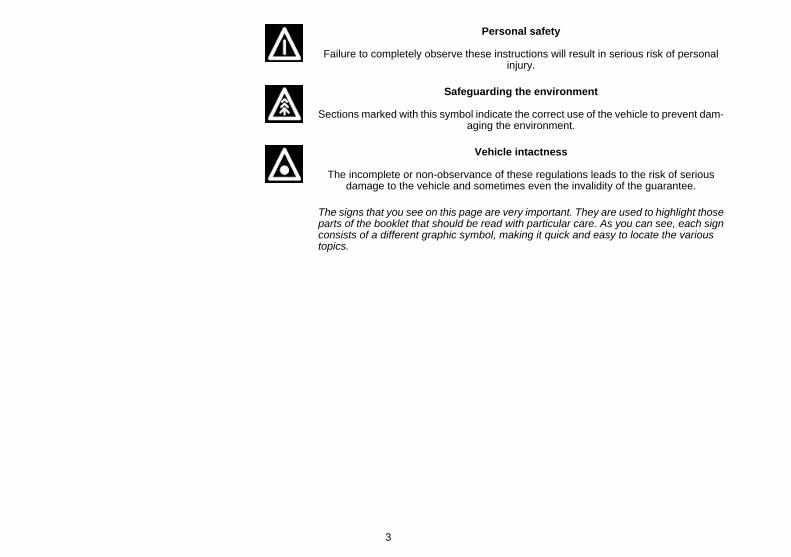
Personal safety
Failure to completely observe these instructions will result in serious risk of personalinjury.
Safeguarding the environment
Sections marked with this symbol indicate the correct use of the vehicle to prevent dam-aging the environment.
Vehicle intactness
The incomplete or non-observance of these regulations leads to the risk of seriousdamage to the vehicle and sometimes even the invalidity of the guarantee.
The signs that you see on this page are very important. They are used to highlight thoseparts of the booklet that should be read with particular care. As you can see, each signconsists of a different graphic symbol, making it quick and easy to locate the varioustopics.
3

4
INDEX
VEHICLE...................................................................................... 7Dashboard................................................................................ 9Analogue instrument panel....................................................... 10Clock......................................................................................... 12Digital lcd display...................................................................... 13
Maintenance icons................................................................ 13*MODE* button...................................................................... 14
Key switch................................................................................. 14Locking the steering wheel.................................................... 14Releasing the steering wheel................................................ 14
Switch direction indicators........................................................ 15Horn button............................................................................... 15Light switch............................................................................... 16Emergency flashing light button................................................ 16Start-up button.......................................................................... 17Engine stop button.................................................................... 17Front suspension unlock-lock switch........................................ 18The immobilizer system............................................................ 18
Keys...................................................................................... 18Immobilizerdevice enabled indicator led............................... 20Operation............................................................................... 20Programming the immobilizer system................................... 21
Saddle opening remote control................................................. 22Remote control programming................................................ 22
Accessing the fuel tank............................................................. 24The saddle................................................................................ 25
Opening the saddle to access the helmet compartment byremote control....................................................................... 26Opening the saddle to access the helmet compartment in anemergency............................................................................. 27
Opening of top box.................................................................... 28Identification.............................................................................. 28
USE.............................................................................................. 29
Checks...................................................................................... 30Refuelling.................................................................................. 31Tyre pressure............................................................................ 33Shock absorbers adjustment.................................................... 34Running in................................................................................. 35Starting up the engine............................................................... 36
Precautions........................................................................... 39Difficult start up......................................................................... 39Stopping the engine.................................................................. 40Stand......................................................................................... 40Automatic transmission............................................................. 41Safe driving............................................................................... 41Front suspension locking system.............................................. 44
MAINTENANCE........................................................................... 49Engine oil level.......................................................................... 50
Engine oil level check............................................................ 50Engine oil top-up................................................................... 50Warning light (insufficient oil pressure)................................. 50Engine oil change.................................................................. 51
Hub oil level.............................................................................. 52Tyres......................................................................................... 54Spark plug dismantlement........................................................ 55Removing the air filter............................................................... 56Air filter cleaning....................................................................... 56Cooling fluid level...................................................................... 57Checking the brake oil level...................................................... 58
Braking system fluid top up................................................... 58Battery....................................................................................... 60
Use of a new battery............................................................. 60Long periods of inactivity.......................................................... 61Fuses........................................................................................ 61Front light group........................................................................ 66
Headlight adjustment............................................................. 66
5

Front direction indicators........................................................... 70Rear optical unit........................................................................ 70Number plate light..................................................................... 72Helmet compartment lighting bulb............................................ 72Rear-view mirrors...................................................................... 73Front and rear disc brake.......................................................... 73Puncture.................................................................................... 74Periods of inactivity................................................................... 75Cleaning the vehicle.................................................................. 75
TECHNICAL DATA...................................................................... 81Kit equipment............................................................................ 85
SPARE PARTS AND ACCESSORIES........................................ 87Warnings................................................................................... 88
PROGRAMMED MAINTENANCE............................................... 91Scheduled maintenance table................................................... 92
6

MP3 250 i.e.
Chap. 01Vehicle
7

01_01
01_02
8
1 Ve
hicl
e
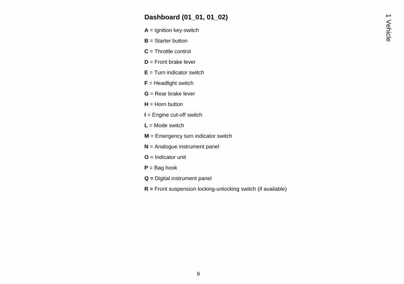
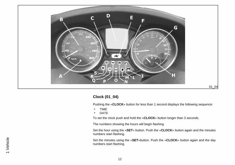
Dashboard (01_01, 01_02)
A = Ignition key-switch
B = Starter button
C = Throttle control
D = Front brake lever
E = Turn indicator switch
F = Headlight switch
G = Rear brake lever
H = Horn button
I = Engine cut-off switch
L = Mode switch
M = Emergency turn indicator switch
N = Analogue instrument panel
O = Indicator unit
P = Bag hook
Q = Digital instrument panel
R = Front suspension locking-unlocking switch (if available)
9
1 Vehicle
01_03
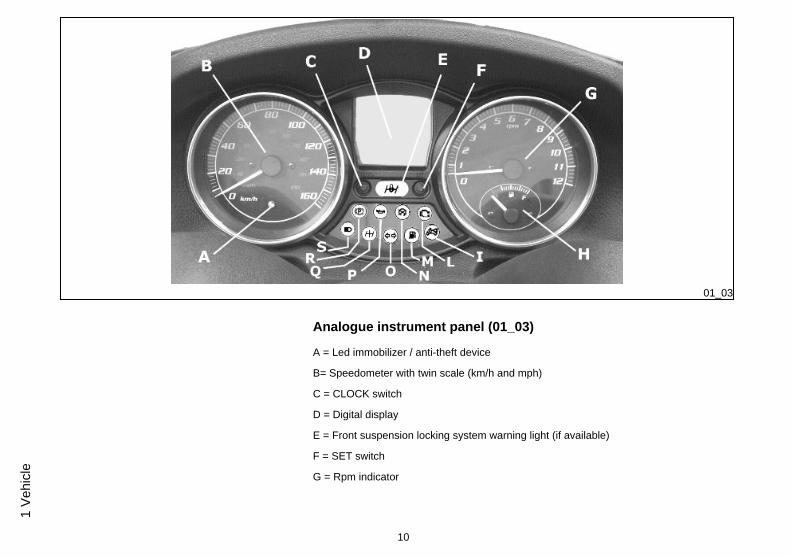
Analogue instrument panel (01_03)
A = Led immobilizer / anti-theft device
B= Speedometer with twin scale (km/h and mph)
C = CLOCK switch
D = Digital display
E = Front suspension locking system warning light (if available)
F = SET switch
G = Rpm indicator
10
1 Ve
hicl
e
H = Fuel gauge
I = Warning light for helmet compartment courtesy light on
L = Engine control telltale light and injection system failure warning light
M = Low fuel warning light
N = Engine stop warning light
D= Turn indicator warning light
P = Low oil pressure warning light
Q = Front suspension locking system failure warning light (if available)
R = Warning light for parking brake engaged
C = High-beam warning light
11
1 Vehicle
01_04
Clock (01_04)
Pushing the «CLOCK» button for less than 1 second displays the following sequence:• TIME• DATE
To set the clock push and hold the «CLOCK» button longer than 3 seconds.
The numbers showing the hours will begin flashing.
Set the hour using the «SET» button. Push the «CLOCK» button again and the minutesnumbers start flashing.
Set the minutes using the «SET»button. Push the «CLOCK» button again and the daynumbers start flashing.
12
1 Ve
hicl
e
Set the day with the «SET» button. Push the «CLOCK» button again and the monthnumbers start flashing.
Set the month with the «SET» button. Push the «CLOCK» button again and the yearnumbers start flashing.
Set the year with the «SET» button. Press the «CLOCK » button again for 4 seconds toexit the adjustment menu.
During the reset process, not pressing any buttons for a period longer than 8 secondsends the process automatically and the display shows the modified time.
01_05
01_06
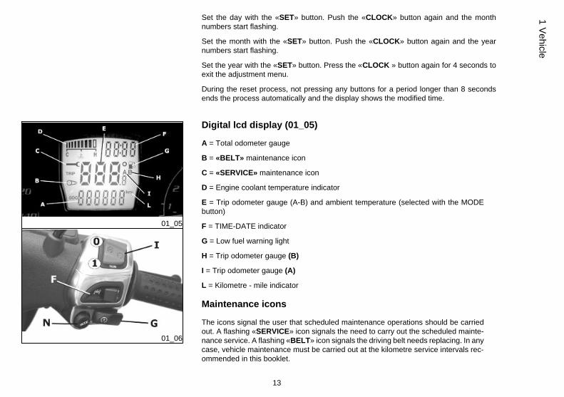
Digital lcd display (01_05)
A = Total odometer gauge
B = «BELT» maintenance icon
C = «SERVICE» maintenance icon
D = Engine coolant temperature indicator
E = Trip odometer gauge (A-B) and ambient temperature (selected with the MODEbutton)
F = TIME-DATE indicator
G = Low fuel warning light
H = Trip odometer gauge (B)
I = Trip odometer gauge (A)
L = Kilometre - mile indicator
Maintenance icons
The icons signal the user that scheduled maintenance operations should be carriedout. A flashing «SERVICE» icon signals the need to carry out the scheduled mainte-nance service. A flashing «BELT» icon signals the driving belt needs replacing. In anycase, vehicle maintenance must be carried out at the kilometre service intervals rec-ommended in this booklet.
13
1 Vehicle
WARNING
REFER TO THE «SCHEDULED MAINTENANCE TABLE» FOR FURTHER MAIN-TENANCE OPERATIONS
*MODE* button (01_06)
Pushing the «MODE» switch (N) for less than a second displays the following functionsequence:
1. Trip odometer "A"2. Trip odometer "B"3. Ambient temperature "°"
Push the «MODE» switch (N) for longer than 3 seconds to zero set the trip odometer
01_07
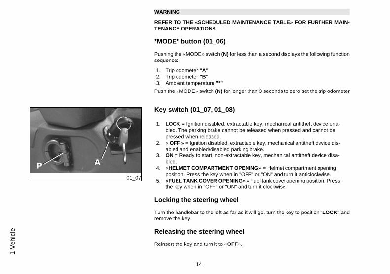
Key switch (01_07, 01_08)
1. LOCK = Ignition disabled, extractable key, mechanical antitheft device ena-bled. The parking brake cannot be released when pressed and cannot bepressed when released.
2. « OFF » = Ignition disabled, extractable key, mechanical antitheft device dis-abled and enabled/disabled parking brake.
3. ON = Ready to start, non-extractable key, mechanical antitheft device disa-bled.
4. «HELMET COMPARTMENT OPENING» = Helmet compartment openingposition. Press the key when in "OFF" or "ON" and turn it anticlockwise.
5. «FUEL TANK COVER OPENING» = Fuel tank cover opening position. Pressthe key when in "OFF" or "ON" and turn it clockwise.
Locking the steering wheel
Turn the handlebar to the left as far as it will go, turn the key to position "LOCK" andremove the key.
Releasing the steering wheel
Reinsert the key and turn it to «OFF».
14
1 Ve
hicl
e
01_08
CAUTION
DO NOT TURN THE KEY TO «LOCK» OR «OFF» WHILE RIDING.
01_09
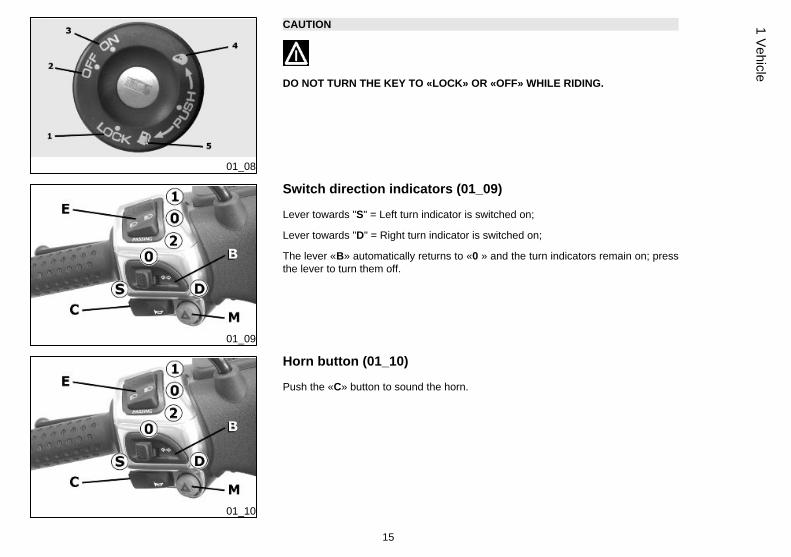
Switch direction indicators (01_09)
Lever towards "S" = Left turn indicator is switched on;
Lever towards "D" = Right turn indicator is switched on;
The lever «B» automatically returns to «0 » and the turn indicators remain on; pressthe lever to turn them off.
01_10
Horn button (01_10)
Push the «C» button to sound the horn.
15
1 Vehicle
01_11
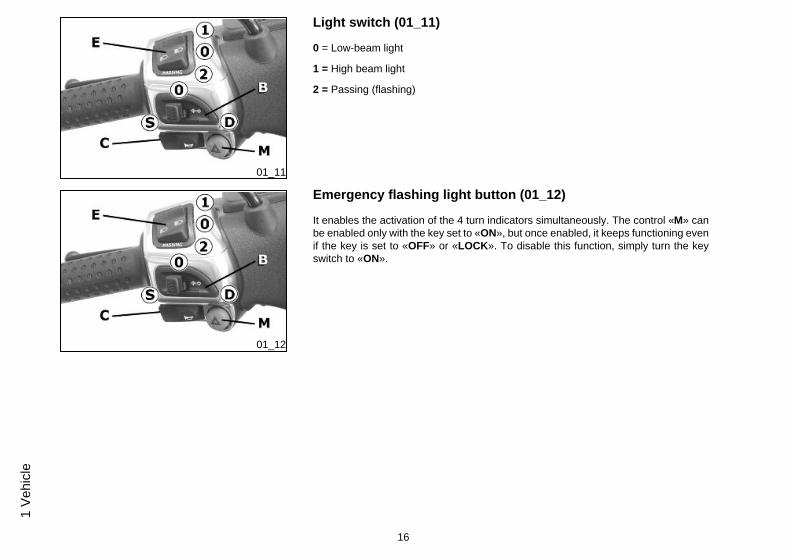
Light switch (01_11)
0 = Low-beam light
1 = High beam light
2 = Passing (flashing)
01_12
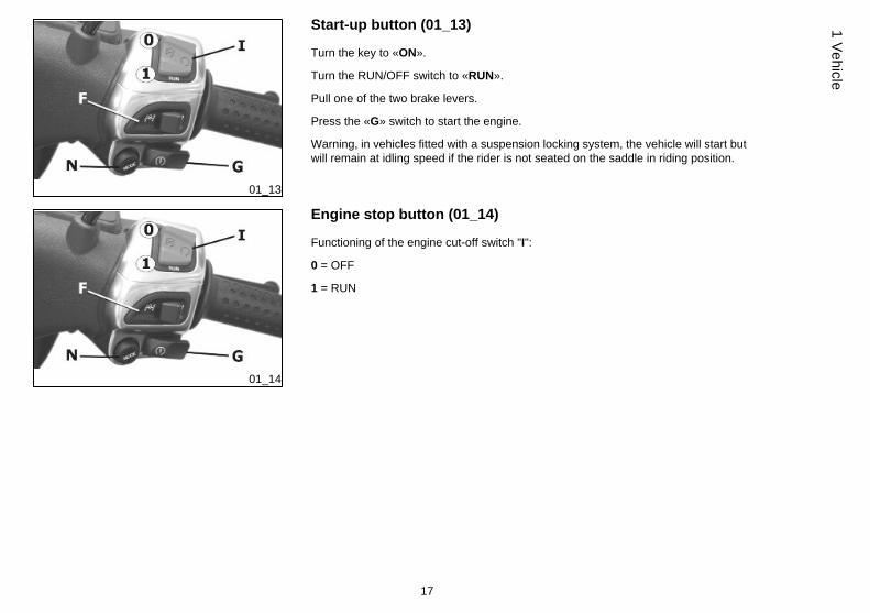
Emergency flashing light button (01_12)
It enables the activation of the 4 turn indicators simultaneously. The control «M» canbe enabled only with the key set to «ON», but once enabled, it keeps functioning evenif the key is set to «OFF» or «LOCK». To disable this function, simply turn the keyswitch to «ON».
16
1 Ve
hicl
e
01_13
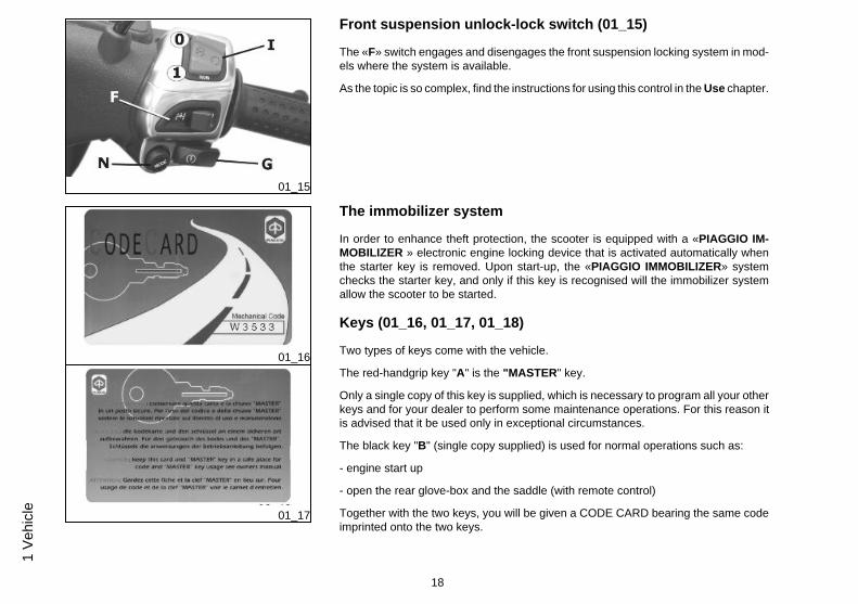
Start-up button (01_13)
Turn the key to «ON».
Turn the RUN/OFF switch to «RUN».
Pull one of the two brake levers.
Press the «G» switch to start the engine.
Warning, in vehicles fitted with a suspension locking system, the vehicle will start butwill remain at idling speed if the rider is not seated on the saddle in riding position.
01_14
Engine stop button (01_14)
Functioning of the engine cut-off switch "I":
0 = OFF
1 = RUN
17
1 Vehicle
01_15
Front suspension unlock-lock switch (01_15)
The «F» switch engages and disengages the front suspension locking system in mod-els where the system is available.
As the topic is so complex, find the instructions for using this control in the Use chapter.
01_16
01_17
The immobilizer system
In order to enhance theft protection, the scooter is equipped with a «PIAGGIO IM-MOBILIZER » electronic engine locking device that is activated automatically whenthe starter key is removed. Upon start-up, the «PIAGGIO IMMOBILIZER» systemchecks the starter key, and only if this key is recognised will the immobilizer systemallow the scooter to be started.
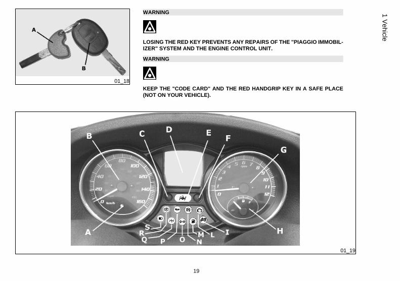
Keys (01_16, 01_17, 01_18)
Two types of keys come with the vehicle.
The red-handgrip key "A" is the "MASTER" key.
Only a single copy of this key is supplied, which is necessary to program all your otherkeys and for your dealer to perform some maintenance operations. For this reason itis advised that it be used only in exceptional circumstances.
The black key "B" (single copy supplied) is used for normal operations such as:
- engine start up
- open the rear glove-box and the saddle (with remote control)
Together with the two keys, you will be given a CODE CARD bearing the same codeimprinted onto the two keys.
18
1 Ve
hicl
e
01_18
WARNING
LOSING THE RED KEY PREVENTS ANY REPAIRS OF THE "PIAGGIO IMMOBIL-IZER" SYSTEM AND THE ENGINE CONTROL UNIT.
WARNING
KEEP THE "CODE CARD" AND THE RED HANDGRIP KEY IN A SAFE PLACE(NOT ON YOUR VEHICLE).
01_19
19
1 Vehicle
Immobilizerdevice enabled indicator led (01_19)
Activation of the "PIAGGIO IMMOBILIZER" system is signalled by a flashing «A» indi-cator. In order to reduce battery discharge, the indicator LED turns off automatically after48 hours of uninterrupted functioning. Should the signal led system break down in itsflashing function, give information about the type of problem to an Authorised Piaggio-Gilera Service Centre.
Operation
Every time the starter key is removed in the "OFF" or "LOCK" position, the safety systemactivates the immobilizer system. Turning the key to "ON" disables the engine lock, pro-vided that the safety system recognises the code transmitted by the key. If the code is notrecognised, turn the key first to "OFF" and then to "ON"; if the lock cannot be disabled,try with the other key supplied (red-coloured). If the engine cannot be started, contact anAuthorised Piaggio Service Centre, which is provided with the electronic equipmentrequired to detect and repair the system.
When additional keys are required, please note that data storage (up to 7 keys max.) mustbe done on all keys, both new ones and existing ones.
Take the red-handgrip key and all the black keys supplied to an Authorised PiaggioService Centre.
The codes of keys not submitted for the new storage procedure are deleted from thememory. Any lost keys will therefore not be enabled to start the engine.
WARNING
EACH KEY HAS ITS OWN AND UNIQUE CODE, WHICH MUST BE STORED BY THESYSTEM CONTROL UNIT.
VIOLENT SHOCKS MAY AFFECT THE ELECTRONIC COMPONENTS OF THE KEY.
20
1 Ve
hicl
e
IF OWNERSHIP OF THE VEHICLE IS TRANSFERRED, THE RED-HANDGRIP KEY(AS WELL AS THE OTHER KEYS) AND THE "CODE CARD" MUST ALSO BE TRANS-FERRED TO THE NEW OWNER.
Programming the immobilizer system
Below is described the procedure to follow for programming the PIAGGIO IMMOBILIZ-ER system and/or for storing other key codes. The programming procedure should becarried out with the engine stop switch set to «RUN».
Procedure start - red key
Insert the red-handgrip key in the switch key (in "OFF" position) and turn it to "ON". After1 - 3 seconds, turn the key to "OFF" again and pull it out.
Intermediate step - black key
After pulling out the red key, insert the black key within 10 seconds and promptly turn itto «ON». After 1-3 seconds, turn the key to "OFF" again and pull it out. In this way, amaximum of 7 black keys can be programmed by repeating the above procedure keepingthe indicated times.
Final step - red key
After pulling out the last black key, insert the red key again and turn it to "ON" (this oper-ation should be performed within 10 seconds of pulling out the previous key). Leave it inthis position for 1 to 3 seconds and return it to the «OFF» position.
21
1 Vehicle
Proper programming check
Insert the red key disabling the transponder (i.e., tilt the key cap by 90°) and turn the keyto "ON". Perform the engine start-up operation. Ensure that the engine does not start.Insert the black key and repeat the start-up operation. Check that engine starts.
WARNING
SHOULD THE ENGINE START WITH THE RED KEY (WITH TRANSPONDER OFF),OR IN THE EVENT OF WRONG OPERATION DURING PROGRAMMING, REPEATTHE PROCEDURE FROM THE BEGINNING.
01_20
01_21
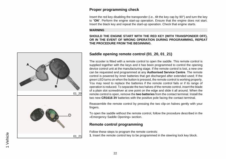
Saddle opening remote control (01_20, 01_21)
The scooter is fitted with a remote control to open the saddle. This remote control issupplied together with the keys and it has been programmed to control the openingdevice control unit at the manufacturing stage. If the remote control is lost, a new onecan be requested and programmed at any Authorised Service Centre. The remotecontrol is powered by inner batteries that get discharged after extended used; If thegreen LED turns on when the button is pressed, the remote control is working properly.You may need to replace the batteries if the remote control fails or if its range ofoperation is reduced. To separate the two halves of the remote control, insert the bladeof a plain slot screwdriver at one point on the edge and slide it all around. When theremote control is open, remove the two batteries from the contact terminal. Install thetwo new CR1616 3V batteries with the positive pole facing the contact terminal.
Reassemble the remote control by pressing the two clip-on halves gently with yourfingers.
To open the saddle without the remote control, follow the procedure described in the«Emergency Saddle Opening» section.
Remote control programming
Follow these steps to program the remote controls:1. Insert the remote control key to be programmed in the steering lock key block.
22
1 Ve
hicl
e
2. Turn the key to «ON», press the button on the remote control, release the button,turn the key back to «OFF» from the «ON» position, all within 4 seconds.
3 Wait 1 to 8 seconds.
4. Repeat steps 2 and 3 for 4 times without removing the key.
The control unit confirms the programming has been successfully executed by open-ing the saddle.
WARNING
TO STORE THE OTHER REMOTE CONTROLS TO MEMORY, (MAXIMUM 8), YOUNEED TO REPEAT THE WHOLE PROCEDURE AGAIN. FAILURE TO CARRY OUTTHESE OPERATIONS WITHIN THE INDICATED TIMES WILL RESULT IN THEAUTOMATIC CANCELLATION OF THE PROCESS FOR PROGRAMMING THEREMOTE-CONTROLLED KEYS.
WARNING
AVOID PRESSING THE REMOTE CONTROL BUTTON MORE THAN ONCE WHENFAR AWAY FROM THE SCOOTER. THE SYNCHRONISM BETWEEN THE RE-MOTE CONTROL AND THE RECEIVER CAN BE IMPAIRED. SHOULD THIS BETHE CASE, REPEAT THE PROGRAMMING PROCEDURE. DO NOT KEEP THEREMOTE CONTROL IN PLACES WITH TEMPERATURES EXCEEDING 60° C THEBATTERY WILL RUN DOWN TOO QUICKLY.
WARNING
TO AVOID BATTERY DISCHARGE, THE SADDLE OPENING REMOTE CONTROLRADIO RECEIVER DEACTIVATES 7 DAYS AFTER THE LAST TIME THE VEHICLEWAS SHUT OFF.
23
1 Vehicle
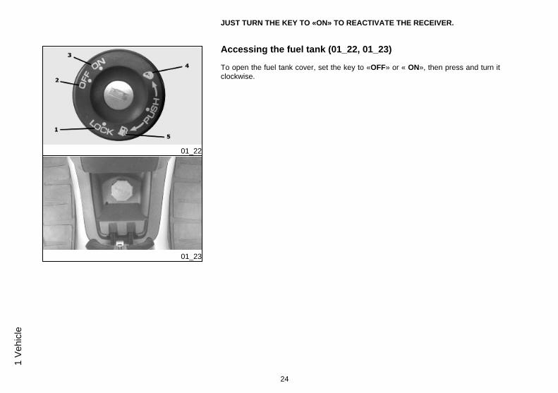
JUST TURN THE KEY TO «ON» TO REACTIVATE THE RECEIVER.
01_22
01_23
Accessing the fuel tank (01_22, 01_23)
To open the fuel tank cover, set the key to «OFF» or « ON», then press and turn itclockwise.
24
1 Ve
hicl
e
01_24
01_25
01_26
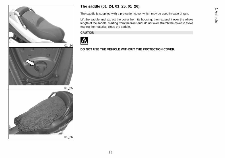
The saddle (01_24, 01_25, 01_26)
The saddle is supplied with a protection cover which may be used in case of rain.
Lift the saddle and extract the cover from its housing, then extend it over the wholelength of the saddle, starting from the front-end; do not over stretch the cover to avoidtearing the material; close the saddle.
CAUTION
DO NOT USE THE VEHICLE WITHOUT THE PROTECTION COVER.
25
1 Vehicle

01_27
Opening the saddle to access the helmet compartment by remotecontrol (01_27)
When the key is in «LOCK» or «OFF» position you can open the saddle using the remotecontrol. The saddle cannot be opened only when the key is set to "ON".
WARNING
OBJECTS INAPPROPRIATELY ARRANGED INSIDE THE HELMET COMPARTMENTMAY DEFORM THE SADDLE CAUSING THE COURTESY LIGHT TO REMAIN ON ANDTHIS WILL DISCHARGE THE BATTERY. IN ANY CASE, THE WARNING LIGHT "I"ON THE INSTRUMENT PANEL SIGNALS IF THE LIGHT IS ON OR OFF.
26
1 Ve
hicl
e

WARNING
THE REMOTE CONTROL OPERATES WITHIN A DISTANCE OF ABOUT 3/5 METRESWITH FULLY CHARGED BATTERIES. WHEN YOU ARE NEAR THE SCOOTER, HAN-DLE THE REMOTE CONTROL CAREFULLY SO AS TO AVOID UNINTENTIONALOPENING OF THE SADDLE. REFER TO THE «OPENING THE SADDLE WITH RE-MOTE CONTROL» SECTION TO REPLACE BATTERIES.
01_28
01_29
Opening the saddle to access the helmet compartment in anemergency (01_28, 01_29)
If the remote control battery or the vehicle battery is discharged, follow these steps toopen the saddle:
1. Open the rear case with the key switch2. Softly press with your hand on the point shown in the photo and in the sense
indicated by the arrow inside the helmet compartment until the saddle closingdevice springs
27
1 Vehicle
01_30
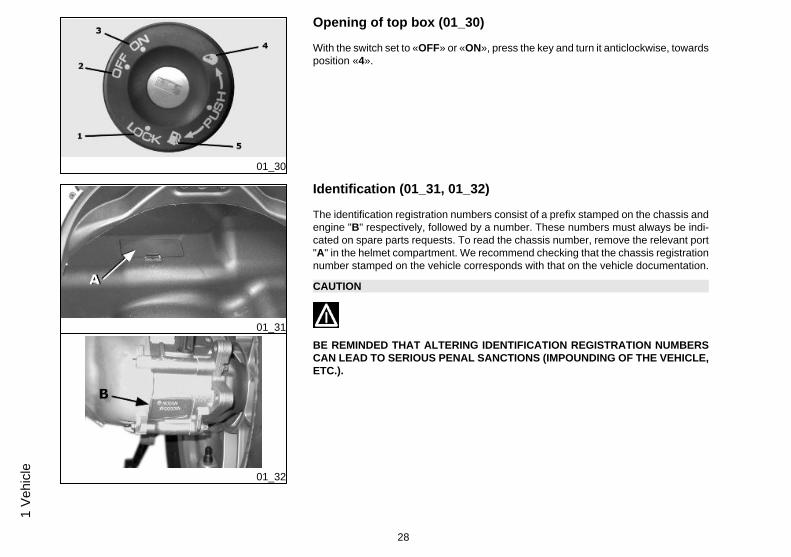
Opening of top box (01_30)
With the switch set to «OFF» or «ON», press the key and turn it anticlockwise, towardsposition «4».
01_31
01_32
Identification (01_31, 01_32)
The identification registration numbers consist of a prefix stamped on the chassis andengine "B" respectively, followed by a number. These numbers must always be indi-cated on spare parts requests. To read the chassis number, remove the relevant port"A" in the helmet compartment. We recommend checking that the chassis registrationnumber stamped on the vehicle corresponds with that on the vehicle documentation.
CAUTION
BE REMINDED THAT ALTERING IDENTIFICATION REGISTRATION NUMBERSCAN LEAD TO SERIOUS PENAL SANCTIONS (IMPOUNDING OF THE VEHICLE,ETC.).
28
1 Ve
hicl
e
MP3 250 i.e.
Chap. 02Use
29
Checks
Before using the vehicle, check:
1. There is enough fuel in the fuel tank.
2. The correct fluid level for front and rear brakes.
3. That tyres are properly inflated.
4. The correct functioning of tail lights, headlamp, turn indicators, stop light and licenseplate light.
5. The correct functioning of front and rear brakes.
6. The oil level in the gearcase.
7. The engine oil level.
8. The coolant level.
02_01
30
2 U
se
02_02
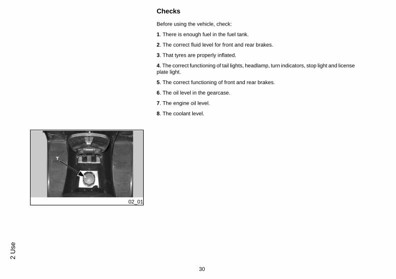
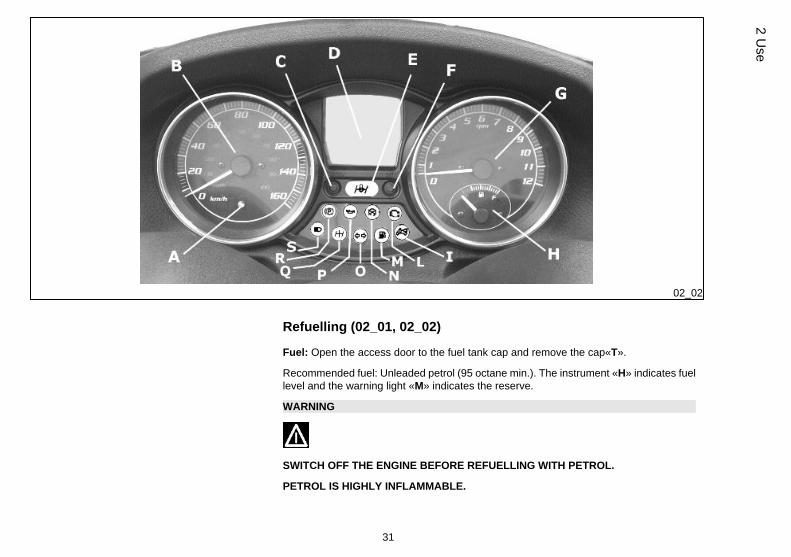
Refuelling (02_01, 02_02)
Fuel: Open the access door to the fuel tank cap and remove the cap«T».
Recommended fuel: Unleaded petrol (95 octane min.). The instrument «H» indicates fuellevel and the warning light «M» indicates the reserve.
WARNING
SWITCH OFF THE ENGINE BEFORE REFUELLING WITH PETROL.
PETROL IS HIGHLY INFLAMMABLE.
31
2 Use

DO NOT SMOKE AND KEEP OPEN FLAMES AT A DISTANCE:FIRE HAZARD.
DO NOT INHALE FUEL FUMES.
DO NOT ALLOW PETROL TO COME INTO CONTACT WITH HOT ENGINE OR ANYPLASTIC PARTS.
CAUTION
PETROL DAMAGES THE PLASTIC PARTS OF THE BODYWORK.
WARNING
DO NOT RIDE WITH THE FUEL TANK ALMOST EMPTY, LACK OF FUEL CAN DAM-AGE THE CATALYTIC CONVERTER.
CAUTION
USING NON-RECOMMENDED PETROL REDUCES THE EFFICIENCY OF THE EX-HAUST AND FUEL SUPPLY SYSTEMS.
CAUTION
DO NOT USE THE VEHICLE TO THE COMPLETE EXHAUSTION OF THE FUEL; INTHE EVENT THAT THIS SHOULD OCCUR, DO NOT ATTEMPT TO START THE EN-GINE. TURN THE KEY SWITCH TO OFF AND TOP-UP THE TANK AS SOON ASPOSSIBLE. FAILURE TO FOLLOW THESE GUIDELINES COULD DAMAGE THEFUEL PUMP AND/OR THE CATALYTIC CONVERTER.
32
2 U
se
WARNING
IT IS HIGHLY INADVISABLE TO REFUEL USING METHODS OTHER THAN NORMALFUEL PUMPS. IF PETROL IS NOT COMPLETELY CLEAN, IT CAN DAMAGE THEFUEL SUPPLY SYSTEM FILTERS.
CAUTION
USING OILS OTHER THAN THOSE RECOMMENDED CAN SHORTEN THE LIFE OFTHE ENGINE.
CharacteristicFuel tank capacity
Tank capacity: ~12 l (approximate value)
Fuel reserve
2 l (approx.)
02_03
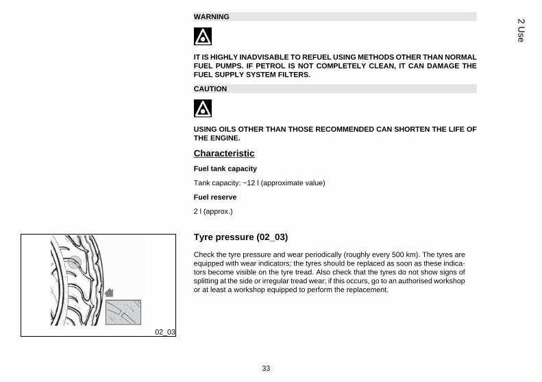
Tyre pressure (02_03)
Check the tyre pressure and wear periodically (roughly every 500 km). The tyres areequipped with wear indicators; the tyres should be replaced as soon as these indica-tors become visible on the tyre tread. Also check that the tyres do not show signs ofsplitting at the side or irregular tread wear; if this occurs, go to an authorised workshopor at least a workshop equipped to perform the replacement.
33
2 Use
CAUTION
TYRE PRESSURE SHOULD BE CHECKED WHEN TYRES ARE COLD.INCOR-RECT TYRE PRESSURE CAUSES ABNORMAL TYRE WEAR AND MAKES RID-ING DANGEROUS.
TYRES MUST BE REPLACED WHEN THE TREAD REACHES THE WEAR LIMITSSET FORTH BY LAW.
CharacteristicFront tyre pressure (rider)
Front tyre pressure (rider): 1.6 bar
Front tyre pressure (rider and passenger)
Front tyre pressure (rider and passenger): 1.8 bar
Rear tyre pressure (rider)
Rear tyre pressure (rider): 2 bar
Rear wheel pressure (rider and passenger):
Rear tyre pressure (rider and passenger): 2.4 bar
02_04
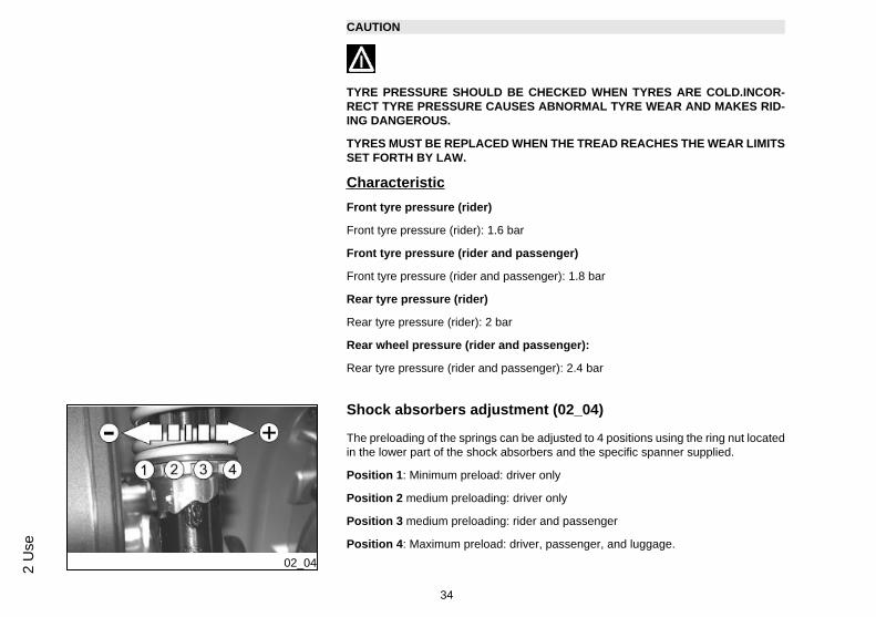
Shock absorbers adjustment (02_04)
The preloading of the springs can be adjusted to 4 positions using the ring nut locatedin the lower part of the shock absorbers and the specific spanner supplied.
Position 1: Minimum preload: driver only
Position 2 medium preloading: driver only
Position 3 medium preloading: rider and passenger
Position 4: Maximum preload: driver, passenger, and luggage.
34
2 U
se
In order to carry out this operation you will need to use the specific spanner in the kit.
CAUTION
RIDING THE VEHICLE WITH THE SPRING PRELOADING NOT CORRECTLY SETFOR THE RIDER AND POSSIBLE PASSENGER, COULD REDUCE THE COM-FORT OF THE RIDE AND THE PRECISION OF THE STEERING.
WARNING
WE RECOMMEND WEARING GLOVES WHILE CARRYING OUT THIS OPERA-TION IN ORDER TO AVOID INJURIES.
WARNING
WE STRONGLY RECOMMEND NOT TO ADJUST BOTH SHOCK ABSORBERSWITH DIFFERENT PRELOADING
Running in
DURING THE FIRST 1000 KM DO NOT RIDE THE VEHICLE OVER 80% OF ITSMAX. SPEED. AVOID OPENING THE THROTTLE GRIP COMPLETELY OR KEEP-ING A CONSTANT SPEED ALONG LONG SECTIONS OF ROAD. AFTER THEFIRST 1000 KM INCREASE SPEED PROGRESSIVELY, IF POSSIBLE, UNTIL THEMAXIMUM PERFORMANCE IS OBTAINED.
35
2 Use
CAUTION
IN ORDER TO AVOID DAMAGING THE VEHICLE, PLEASE COMPLY WITH THERULES LISTED ABOVE.
02_05
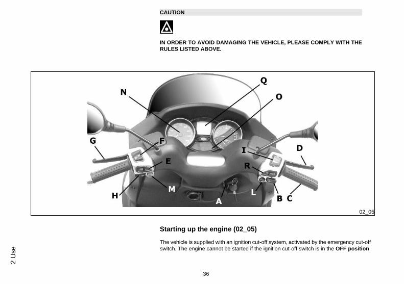
Starting up the engine (02_05)
The vehicle is supplied with an ignition cut-off system, activated by the emergency cut-offswitch. The engine cannot be started if the ignition cut-off switch is in the OFF position
36
2 U
se
A running engine automatically switches off when the ignition cut-off switch is set toOFF.
The scooter is equipped with automatic transmission with direct drive, so that starting iseffected by turning the throttle grip to idle speed; to start-off from still, progressively twistthe throttle grip. The vehicle is equipped with an electrical fuel pump that switches onautomatically as soon as the engine is started. To start the vehicle, before pressing thestarter button «B», pull and keep pulled the front brake lever «D» or the rear brake lever«G» that operates the corresponding ignition consent switches. Besides, if the vehicle hasa front suspension locking system, a sensor placed under the saddle will prevent vehiclemotion, but not ignition, if the rider is not seated in riding position.
1. Rest the vehicle on its centre-stand, ensuring the rear wheel is not touching the ground.
2. Maintain the throttle "C" completely untwisted.
3. Insert the key into the ignition switch "A" and turn it onto the ON position.
4. Make sure that the "I" switch is set onto the ON position.
5. Pull either the front, "D", or rear brake lever, "G", while pressing the starter button "B".
WARNING
THE AUTOMATIC TRANSMISSION MAKES THE REAR WHEEL TURN EVEN WHENTHE THROTTLE IS SLIGHTLY TWISTED. RELEASE THE BRAKE CAREFULLY AF-TER STARTING, AND THEN ACCELERATE GRADUALLY.
CAUTION
DO NOT START-UP THE ENGINE IN CLOSED AREAS BECAUSE EXHAUST GASESARE TOXIC.
37
2 Use

CAUTION
DUE TO THE HIGH TEMPERATURES THE CATALYTIC CONVERTER CAN REACH,ALWAYS TAKE CARE, WHEN PARKING THE SCOOTER, THAT THE EXHAUSTDOES NOT COME INTO CONTACT WITH FLAMMABLE MATERIALS, TO AVOID SE-RIOUS BURNS.
CAUTION
DO NOT SWITCH OFF THE ENGINE WHILE THE VEHICLE IS MOVING. UNBURNEDFUEL COULD ENTER THE CATALYTIC CONVERTER AND BURN, CAUSING IT TOOVERHEAT AND POSSIBLY DESTROYING IT.
CAUTION
NEITHER PUSH THE STARTER BUTTON NOR TURN THE KEY SWITCH TO «ON»WHEN THE TANK IS EMPTY SINCE THE START-UP SYSTEM MAY GET DAMAGED.
WARNING
NEVER TRY TO START-UP THE ENGINE WITH THE THROTTLE GRIP TWISTED.THIS MAY LEAD TO LOSING CONTROL OF THE VEHICLE AND TO ROLLOVER,WITH CONSEQUENT SERIOUS OR, IN SOME CASES, LETHAL INJURIES.
38
2 U
se

Precautions
CAUTION
NEVER STRESS THE ENGINE AT LOW TEMPERATURES IN ORDER TO AVOIDPOSSIBLE DAMAGE. BE CAREFUL NEVER TO EXCEED THE MAXIMUM SPEEDWHILE RUNNING DOWNHILL, IN ORDER TO AVOID DAMAGING THE ENGINE. INANY CASE, IN ORDER TO PRESERVE THE ENGINE FROM PROLONGED EXCES-SIVE REVOLUTIONS, THE REVOLUTION LIMITER WILL BE ACTIVATED IF THEENGINE SPEED EXCEEDS THE ESTABLISHED THRESHOLD.
WARNING
AFTER A LONG DISTANCE COVERED AT THE MAXIMUM SPEED, DO NOT STOPTHE ENGINE IMMEDIATELY, BUT LET IT RUN AT IDLE FOR A FEW SECONDS.
Difficult start up
In the rare case of flooding the engine, to facilitate start-up, it is possible to try to putthe vehicle into action with the gas hand grip partially or completely open. It is howevernecessary, once the engine is started, to take your vehicle to an Authorised ServiceCentre to determine the cause of this problem and to re-establish the vehicle properfunctioning.
39
2 Use

02_06
Stopping the engine (02_06)
Fully untwist the throttle grip, then rotate the key in the switch «A » to «KEYOFF» (extractable key).
CAUTION
DUE TO THE HIGH TEMPERATURES THE CATALYTIC CONVERTER CANREACH, ALWAYS TAKE CARE, WHEN PARKING THE SCOOTER, THAT THEEXHAUST DOES NOT COME INTO CONTACT WITH FLAMMABLE MATERIALS,TO AVOID SERIOUS BURNS.
CAUTION
DO NOT SWITCH OFF THE ENGINE WHILE THE VEHICLE IS MOVING. UN-BURNED FUEL COULD ENTER THE CATALYTIC CONVERTER AND BURN,CAUSING IT TO OVERHEAT AND POSSIBLY DESTROYING IT.
02_07
Stand (02_07)
CENTRE STAND
With your foot push the projection of the centre stand «F » while lifting the vehiclebackwards, holding onto the side handles.
40
2 U
se

Automatic transmission
To ensure simple, pleasurable riding, the vehicle is equipped with automatic trans-mission with regulator and centrifugal clutch. The system is designed to provide thebest performance (acceleration and consumption) while riding on both flat roads anduphill.
If you have to stop on an uphill slope (traffic lights, traffic jam, etc.) use only the braketo keep the vehicle still, leaving the engine running at idle speed. Using theengine to keep the vehicle still can cause the clutch to overheat, due to thefriction of the clutch masses against the capstan. Besides, avoid acceleratingwith the hand brake engaged. It is therefore recommended to avoid conditions ofprolonged clutch slippage (besides those previously indicated) like driving uphill fullyladen on steep slopes or starting off with driver and passenger at slopes greater than25%.
Observe the following precautions if the clutch overheats:
1. Do not continue riding in such conditions.
2. Let the clutch cool down with the engine at idle speed for a few minutes.
Safe driving
In the following we offer some simple advice, that will allow for the daily use of yourscooter in greater safety and peace of mind. Your skill and your mechanical knowledgeare the basis of a safe ride. We recommend trying out the vehicle in traffic - free zones,in order to acquire a good knowledge of the vehicle it self.
1. Before riding off, remember to put on your helmet and fasten it correctly.
2.Reduce speed on rough roads and drive with care.
3. After driving on a long stretch of wet road without using the brakes, the brakingeffect is initially lower. In these conditions, it is a good idea to apply the brakes fromtime to time.
4. Avoid riding off by mounting the scooter when resting on the support. In any case,the rear wheel should not be turning when in comes into contact with the ground, inorder to avoid abrupt departures.
41
2 Use
5. If driving over roads affected by sand, mud, snow mixed with salt, etc. we recom-mend cleaning the brake disc with a non-corrosive detergent frequently in order toprevent corrosive particles from building up in the holes, which may cause early breakpad wear.
CAUTION
ALWAYS RIDE WITHIN YOUR LIMITS RIDING UNDER THE INFLUENCE OF AL-COHOL OR OTHER DRUGS AND CERTAIN MEDICATIONS IS EXTREMELY DAN-GEROUS.
CAUTION
IN ORDER TO PREVENT ANY ACCIDENTS RIDE VERY CAREFULLY AFTERADDING ACCESSORIES AND WHILE CARRYING LUGGAGE. ADDING ACCES-SORIES AND LUGGAGE CAN REDUCE THE VEHICLE'S STABILITY, PERFORM-ANCE AND SAFETY DURING USE.
WARNING
NEVER RIDE THE SCOOTER EQUIPPED WITH ACCESSORIES (TOP BOX AND/OR WINDSHIELD) AT A SPEED HIGHER THAN 100 km/h.
THE SCOOTER CAN BE RIDDEN AT A HIGHER SPEED WITHOUT THE ACCES-SORIES MENTIONED BEFORE WITHIN THE LIMITS ESTABLISHED BY LAW.
IF THERE SHOULD BE NOT-PIAGGIO ACCESSORIES INSTALLED, OR AN AB-NORMAL LOAD, OR IF THE SCOOTER IS NOT IN A GENERALLY GOOD CON-DITION, OR WHENEVER WEATHER CONDITIONS DEMAND IT, SPEED SHOULDBE REDUCED FURTHER.
42
2 U
se

CAUTION
DO NOT ADJUST THE MIRRORS WHILE RIDING. THIS COULD CAUSE YOU TOLOOSE CONTROL OF THE VEHICLE.
CAUTION
ANY CHANGES TO THE VEHICLE PERFORMANCE AS WELL AS ALTERATIONSTO ORIGINAL STRUCTURAL PARTS IS STRICTLY FORBIDDEN BY LAW, ANDRENDERS THE VEHICLE NO LONGER CONFORMING TO THE APPROVED TYPEAND DANGEROUS FOR RIDING.
43
2 Use

02_08
02_09
Front suspension locking system (02_08, 02_09, 02_10, 02_11,02_12)
The following point corresponds only to versions with front suspension lockingsystem.
The front suspension locking system simply prevents vehicle tilting when the "T"switch is pressed. The vehicle can be stopped without your feet touching the ground.
The warning light "E" starts flashing when the key switch is set to "ON". This meansthat the system is enabled for locking activation.
When the "T" switch is turned to "1", a continuous sound alarm signals that the lockingsystem is engaged and, at the same time, the warning light "E" turns steadily on.
44
2 U
se

02_10
02_11
02_12
When the "T" switch is turned to "2", an intermittent sound alarm signals that thelocking system is disengaged and, at the same time, the warning light "E" startsflashing again. Warning light "E" turns on to start riding. This means that the systemallows for vehicle tilting.
Engaging tilt locking is possible only if the following conditions occur at the same time:
• Throttle completely untwisted• Engine rpm below 2500rpm• Vehicle speed below 10 km/h• Locking system WARNING light "Q" off (the system has not detected fail-
ures)If one of these conditions is not fulfilled, the warning light "E" remains off and lockingcannot be engaged (in normal riding conditions, the warning light "E" is off).
With engine on, system locked and warning light "E" on, the suspension locking sys-tem is disengaged automatically and the warning light "E" turns off when the throttleis twisted to start the ride.
For riders' safety, the vehicle has a rider detection sensor in the saddle which ena-bles the system to prevent vehicle motion and suspension unlocking (in case of lockedsuspension) when the rider is not properly seated in riding position: in such case, theWARNING light «Q» turns on steadily
CAUTION
THE RIDER DETECTION SENSOR IS LOCATED IN THE FRONT PART OF THESADDLE. AVOID PLACING BAGS OR HEAVY OBJECTS ACCIDENTALLY ONTHE SADDLE.
NOT OBSERVING THIS RULE MAY MOVE THE VEHICLE FORWARD AND RE-LEASE THE SUSPENSION LOCKING SYSTEM EVEN IF THE RIDER IS NOTSEATED, BY SIMPLY TWISTING THE THROTTLE. THE VEHICLE COULD FALLACCIDENTALLY AS A CONSEQUENCE.
45
2 Use

WARNING
EVERY TIME THE VEHICLE IS STOPPED, MAKE SURE THE FRONT SUSPEN-SION LOCKING SYSTEM IS ENGAGED. OTHERWISE, PLACE YOUR FEET ONTHE GROUND TO KEEP THE VEHICLE UPRIGHT.
WARNING
AVOID USING THE LOCKING SYSTEM WHEN RIDING THE VEHICLE ALONG IR-REGULAR ROADS OR ROADS WITH OBSTACLES(E.G. ROAD HUMPS, SIDE-WALK, ETC.).
IN CASE OF ENGINE FAILURE (DISCHARGED BATTERY) AVOID PULLING THEVEHICLE WITH THE LOCKING SYSTEM ENGAGED.
WITH THE LOCKING SYSTEM ENGAGED AND THE ENGINE OFF, AVOID MOV-ING THE VEHICLE AT SPEEDS ABOVE 5 Km/h.
WARNING
IF THE RIDER IS NOT SEATED ON THE SADDLE WHILE THE VEHICLE IS INMOTION AND THE LOCKING SYSTEM IS ENGAGED, AVOID OPERATING THETHROTTLE CONTROL PURPOSELESSLY AS THIS MAY DAMAGE THE CATA-LYTIC CONVERTER.
CAUTION
DO NOT RIDE DOWNHILL WITH THE SUSPENSION LOCKING SYSTEM ENGAG-ED AND THE KEY SWITCH SET TO OFF.
46
2 U
se
With the vehicle off and the suspension locking system engaged, it is possible to getoff the scooter without using the stand. For safety reasons, it is recommended to pressthe hand brake lever shown in the figure, moving it form "0" to "1".
Warning light "R" on the instrument panel turns on when the hand brake is engaged.
When the hand brake is engaged and the key switch is turned to "1", the safety systemthat prevents the hand brake from getting released is activated. To release the handbrake, turn the key switch to "2" or "3". If the switch is set to "1" , the hand brake canalso be engaged.
If the WARNING light "Q" turns on (flashes), it means that there is a failure in the frontsuspension locking system. Therefore, it is necessary to take your vehicle to a PiaggioService Center. If the front suspension is locked, it can be unlocked by quickly oper-ating the"T" switch twice to the unlocking position "2". Once the suspension isunlocked, the vehicle can be normally used, except for the locking system which willbe disengaged.
For some cases of failure, the vehicle speed is auto-limited to 30 Km/h. This automaticprocedure is activated to enhance safety until the failure is eliminated.
Always contact a Piaggio Service Center
If the continuous sound alarm is activated when the WARNING light "Q" turns on(steadily), try unlocking the system by operating the "T" switch twice to the unlockingposition "2". If it cannot be unlocked, take your vehicle to a Piaggio Service Cen-ter at once.
47
2 Use

48
2 U
se
MP3 250 i.e.
Chap. 03Maintenance
49
03_01
03_02
03_03
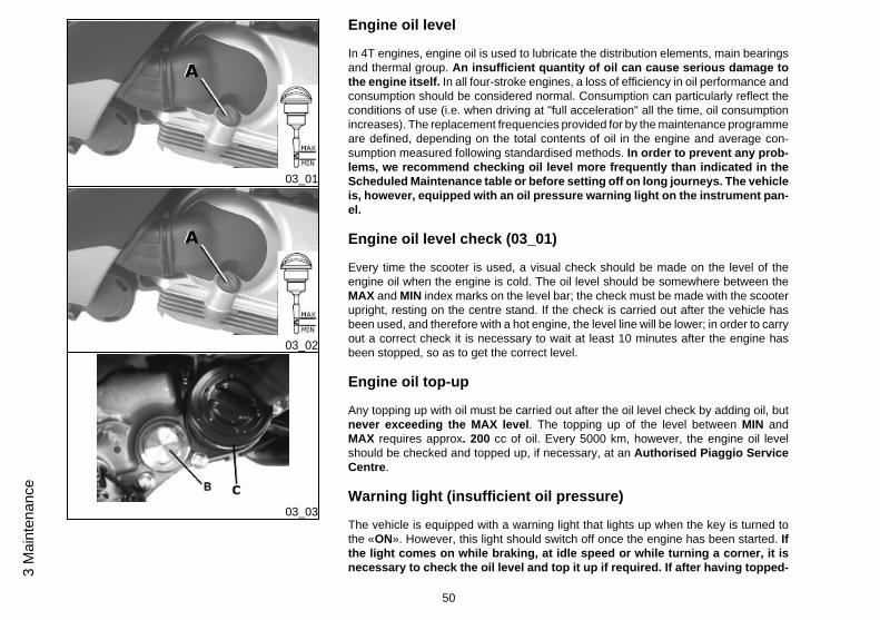
Engine oil level
In 4T engines, engine oil is used to lubricate the distribution elements, main bearingsand thermal group. An insufficient quantity of oil can cause serious damage tothe engine itself. In all four-stroke engines, a loss of efficiency in oil performance andconsumption should be considered normal. Consumption can particularly reflect theconditions of use (i.e. when driving at "full acceleration" all the time, oil consumptionincreases). The replacement frequencies provided for by the maintenance programmeare defined, depending on the total contents of oil in the engine and average con-sumption measured following standardised methods. In order to prevent any prob-lems, we recommend checking oil level more frequently than indicated in theScheduled Maintenance table or before setting off on long journeys. The vehicleis, however, equipped with an oil pressure warning light on the instrument pan-el.
Engine oil level check (03_01)
Every time the scooter is used, a visual check should be made on the level of theengine oil when the engine is cold. The oil level should be somewhere between theMAX and MIN index marks on the level bar; the check must be made with the scooterupright, resting on the centre stand. If the check is carried out after the vehicle hasbeen used, and therefore with a hot engine, the level line will be lower; in order to carryout a correct check it is necessary to wait at least 10 minutes after the engine hasbeen stopped, so as to get the correct level.
Engine oil top-up
Any topping up with oil must be carried out after the oil level check by adding oil, butnever exceeding the MAX level. The topping up of the level between MIN andMAX requires approx. 200 cc of oil. Every 5000 km, however, the engine oil levelshould be checked and topped up, if necessary, at an Authorised Piaggio ServiceCentre.
Warning light (insufficient oil pressure)
The vehicle is equipped with a warning light that lights up when the key is turned tothe «ON». However, this light should switch off once the engine has been started. Ifthe light comes on while braking, at idle speed or while turning a corner, it isnecessary to check the oil level and top it up if required. If after having topped-
50
3 M
aint
enan
ce
up the oil, the warning light still comes on while braking, at idle speed or whileturning a corner, it will be necessary to take your vehicle to an Authorised Serv-ice Centre.
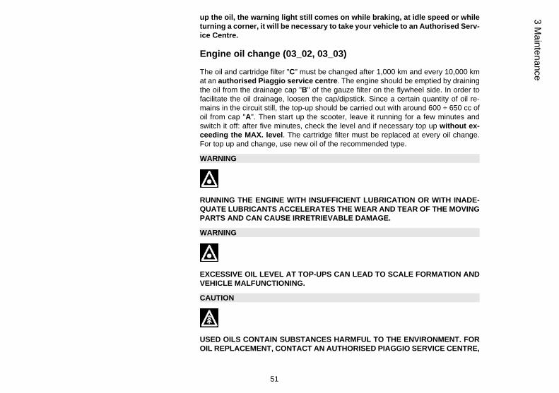
Engine oil change (03_02, 03_03)
The oil and cartridge filter "C" must be changed after 1,000 km and every 10,000 kmat an authorised Piaggio service centre. The engine should be emptied by drainingthe oil from the drainage cap "B" of the gauze filter on the flywheel side. In order tofacilitate the oil drainage, loosen the cap/dipstick. Since a certain quantity of oil re-mains in the circuit still, the top-up should be carried out with around 600 ÷ 650 cc ofoil from cap "A". Then start up the scooter, leave it running for a few minutes andswitch it off: after five minutes, check the level and if necessary top up without ex-ceeding the MAX. level. The cartridge filter must be replaced at every oil change.For top up and change, use new oil of the recommended type.
WARNING
RUNNING THE ENGINE WITH INSUFFICIENT LUBRICATION OR WITH INADE-QUATE LUBRICANTS ACCELERATES THE WEAR AND TEAR OF THE MOVINGPARTS AND CAN CAUSE IRRETRIEVABLE DAMAGE.
WARNING
EXCESSIVE OIL LEVEL AT TOP-UPS CAN LEAD TO SCALE FORMATION ANDVEHICLE MALFUNCTIONING.
CAUTION
USED OILS CONTAIN SUBSTANCES HARMFUL TO THE ENVIRONMENT. FOROIL REPLACEMENT, CONTACT AN AUTHORISED PIAGGIO SERVICE CENTRE,
51
3 Maintenance
AS THEY ARE EQUIPPED TO DISPOSE OF SPENT OILS IN AN ENVIRONMEN-TALLY FRIENDLY AND LEGAL WAY.
CAUTION
USING OILS OTHER THAN THOSE RECOMMENDED CAN SHORTEN THE LIFEOF THE ENGINE.
Recommended productsAGIP CITY HI TEC 4T
Engine oilSAE 5W-40, API SL, ACEA A3, JASO MA Synthetic oil
03_04
03_05
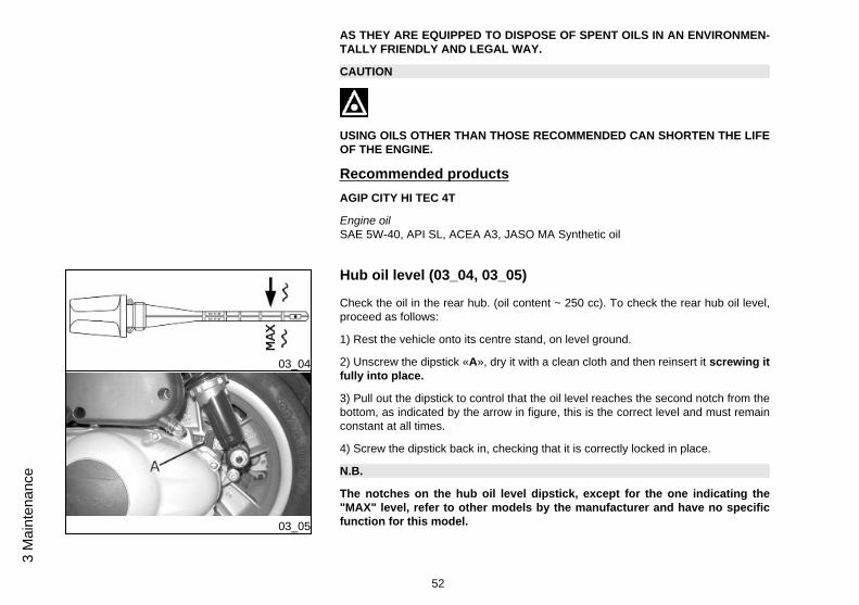
Hub oil level (03_04, 03_05)
Check the oil in the rear hub. (oil content ~ 250 cc). To check the rear hub oil level,proceed as follows:
1) Rest the vehicle onto its centre stand, on level ground.
2) Unscrew the dipstick «A», dry it with a clean cloth and then reinsert it screwing itfully into place.
3) Pull out the dipstick to control that the oil level reaches the second notch from thebottom, as indicated by the arrow in figure, this is the correct level and must remainconstant at all times.
4) Screw the dipstick back in, checking that it is correctly locked in place.
N.B.
The notches on the hub oil level dipstick, except for the one indicating the"MAX" level, refer to other models by the manufacturer and have no specificfunction for this model.
52
3 M
aint
enan
ce

CAUTION
RIDING THE VEHICLE WITH INSUFFICIENT HUB LUBRICATION OR WITH CON-TAMINATED OR IMPROPER LUBRICANTS ACCELERATES THE WEAR ANDTEAR OF THE MOVING PARTS AND CAN CAUSE SERIOUS DAMAGE.
CAUTION
USED OIL CAN HARM THE ENVIRONMENT. COLLECTION AND DISPOSALSHOULD BE CARRIED OUT IN COMPLIANCE WITH CURRENT REGULATIONS.
CAUTION
AN EXCESSIVE QUANTITY OF OIL CAN LEAD TO LEAKAGE, WHICH MAYCAUSE THE ENGINE AND THE WHEEL TO GET DIRTY.
CAUTION
WHEN REPLACING THE HUB OIL DO NOT LET THE OIL COME INTO CONTACTWITH THE REAR BRAKE DISC.
CAUTION
FOR OIL REPLACEMENT, CONTACT ANY AUTHORISED SERVICE CENTRE ASTHEY ARE EQUIPPED TO DISPOSE OF USED OILS IN AN ENVIRONMENTALLYFRIENDLY AND LEGAL WAY.
53
3 Maintenance

CharacteristicRear hub oil
250 cc
03_06
Tyres (03_06)
WARNING
THE WHEELS FITTED WITH TYRES SHOULD ALWAYS BE BALANCED. RIDINGTHE VEHICLE WITH VERY LOW TYRE PRESSURE OR WITH INCORRECTLYBALANCED TYRES CAN LEAD TO DANGEROUS STEERING VIBRATIONS.
CharacteristicFront tyre pressure (rider)
Front tyre pressure (rider): 1.6 bar
Front tyre pressure (rider and passenger)
Front tyre pressure (rider and passenger): 1.8 bar
Rear tyre pressure (rider)
Rear tyre pressure (rider): 2 bar
Rear wheel pressure (rider and passenger):
Rear tyre pressure (rider and passenger): 2.4 bar
54
3 M
aint
enan
ce
03_07
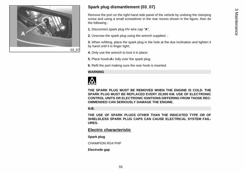
Spark plug dismantlement (03_07)
Remove the port on the right-hand side panel of the vehicle by undoing the clampingscrew and using a small screwdriver in the rear recess shown in the figure, then dothe following :
1. Disconnect spark plug HV wire cap "A";
2. Unscrew the spark plug using the wrench supplied. ;
3. When refitting, place the spark plug in the hole at the due inclination and tighten itby hand until it is finger tight;
4. Only use the wrench to lock it in place;
5. Place hood«A» fully over the spark plug.
6. Refit the port making sure the rear hook is inserted.
WARNING
THE SPARK PLUG MUST BE REMOVED WHEN THE ENGINE IS COLD. THESPARK PLUG MUST BE REPLACED EVERY 20,000 KM. USE OF ELECTRONICCONTROL UNITS OR ELECTRONIC IGNITIONS DIFFERING FROM THOSE REC-OMMENDED CAN SERIOUSLY DAMAGE THE ENGINE.
N.B.
THE USE OF SPARK PLUGS OTHER THAN THE INDICATED TYPE OR OFSHIELDLESS SPARK PLUG CAPS CAN CAUSE ELECTRICAL SYSTEM FAIL-URES.
Electric characteristicSpark plug
CHAMPION RG4 PHP
Electrode gap
55
3 Maintenance

0.7 ÷ 0.8 mm
03_08
Removing the air filter (03_08)
Proceed as follows:
Undo the clamping screws «A» (two of which are on the knob-type head) and removethe air-box cover.
Air filter cleaning
1. Wash the sponge with water and neutral soap.
2. Dry it with a clean cloth and small blasts of compressed air.
3. Impregnate the sponge with a mixture of 50% petrol and 50% specified oil.
4. Gently squeeze the filter element, let it drip and then refit it.
CAUTION
IF THE VEHICLE IS USED ON DUSTY ROADS IT IS NECESSARY TO CARRY OUTMAINTENANCE CONTROLS OF THE AIR FILTER TO AVOID DAMAGING THEENGINE.
Recommended productsAGIP FILTER OIL
Oil for air filter spongeMineral oil with specific additives for increased adhesiveness
56
3 M
aint
enan
ce

03_09
03_10
03_11
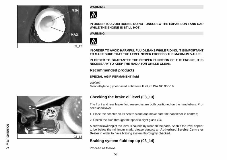
Cooling fluid level (03_09, 03_10, 03_11, 03_12)
The engine cooling system operates by forcing circulation of fluid. The cooling circuitcontains about 2 litres of coolant consisting of a mixture of 50% de-ionised water andglycol ethylene-based antifreeze solution with corrosion inhibitors. Recommendedcoolant, supplied with already mixed and ready for use fluid. For proper functioning ofthe engine, the coolant temperature must be between the 4th and 7th lit segment, asindicated by the instrument «D» on the digital instrument panel. When the 9th lightsup, the icon and all the segments start flashing; stop the engine, let it cool down andcheck the fluid level; if the result is normal, take your vehicle to an Authorised PiaggioService Centre.
The fluid inspection should be carried out every 6,000 km when the engine is cold,fol-lowing the methods indicated below.
a) Rest the vehicle in vertical position on the stand and remove the screw of the ex-pansion tank cap shown in the photo
b) Remove the expansion tank cover "A", turning in anticlockwise direction.
c) Look inside the expansion tank; the fluid level must always be between the min andthe max level
d) If the coolant level is near the minimum mark, top up when the engine is cold.
If it is necessary to top up the coolant frequently, or if the expansion tank is completelydry, you should look for the cause in the cooling system. It is therefore indispensableto have the cooling system checked at an Authorised Piaggio Service Centre. Thecoolant should be replaced every 2 years. Take your vehicle to an Authorised Piag-gio Service Centre for this operation.
N.B.
SHOULD THE 9th SEGMENT OF THE COOLANT TEMPERATURE INDICATORCOME ON DURING A NON-DEMANDING RIDE, SHUT OFF THE ENGINE AND LETIT COOL DOWN. THEN CHECK THE COOLANT LEVEL; IF THE LEVEL IS OK,CONTACT AN AUTHORISED SERVICE CENTRE.
57
3 Maintenance
03_12
WARNING
IN ORDER TO AVOID BURNS, DO NOT UNSCREW THE EXPANSION TANK CAPWHILE THE ENGINE IS STILL HOT.
WARNING
IN ORDER TO AVOID HARMFUL FLUID LEAKS WHILE RIDING, IT IS IMPORTANTTO MAKE SURE THAT THE LEVEL NEVER EXCEEDS THE MAXIMUM VALUE.
IN ORDER TO GUARANTEE THE PROPER FUNCTION OF THE ENGINE, IT ISNECESSARY TO KEEP THE RADIATOR GRILLE CLEAN.
Recommended productsSPECIAL AGIP PERMANENT fluid
coolantMonoethylene glycol-based antifreeze fluid, CUNA NC 956-16
03_13
Checking the brake oil level (03_13)
The front and rear brake fluid reservoirs are both positioned on the handlebars. Pro-ceed as follows:
1. Place the scooter on its centre stand and make sure the handlebar is centred;
2. Check the fluid through the specific sight glass «C».
A certain lowering of the level is caused by wear on the pads. Should the level appearto be below the minimum mark, please contact an Authorised Service Centre orDealer in order to have braking system thoroughly checked.
Braking system fluid top up (03_14)
Proceed as follows:
58
3 M
aint
enan
ce

03_14
Loosen the fixing screws "B" and lift the plastic cover "A" in order to access the brakereservoir. Loosen the two fixing screws and remove the reservoir cover; top-up withthe recommended fluid without exceeding the 'MAX.' mark.
This procedure applies to the rear brake pump top-up operation; follow the same pro-cedure for the front brake pump.
Under normal climatic conditions, the brake fluid should be replaced every 2 years.
This operation must be carried out by trained technicians; please contact your nearestPIAGGIO dealer or an authorised service centre.
WARNING
ONLY USE DOT 4 CLASS BRAKE FLUIDS. COOLING SYSTEM FLUIDS AREHIGHLY CORROSIVE. MAKE SURE THAT IT DOES NOT COME INTO CONTACTWITH THE PAINTWORK.
CAUTION
AVOID CONTACT OF BRAKE FLUID WITH EYES, SKIN, AND CLOTHING. INCASE OF CONTACT, RINSE WITH WATER. THE BRAKING CIRCUIT FLUID ISHYGROSCOPIC, THAT IS, IT ABSORBS HUMIDITY FROM THE SURROUNDINGAIR. IF THE HUMIDITY IN THE BRAKING FLUID EXCEEDS A CERTAIN VALUE,IT WILL LEAD TO INEFFICIENT BRAKING. NEVER USE BRAKING FLUID KEPTIN CONTAINERS THAT HAVE ALREADY BEEN OPENED, OR PARTIALLY USED.
Recommended productsAGIP BRAKE 4
Brake fluidFMVSS DOT 4 Synthetic fluid
59
3 Maintenance

03_15
Battery (03_15)
To access the battery, proceed as follows:
1. Place the scooter on its centre stand;
2. Open the saddle, following the previously described procedure;
3. Remove the two fasteners "A" and the cover "B".
WARNING
IN ORDER TO AVOID DAMAGING THE ELECTRICAL SYSTEM, NEVER DISCON-NECT THE WIRING WHILE THE ENGINE IS RUNNING.
Use of a new battery
Make sure that the terminals are connected correctly.
CAUTION
DO NOT REVERSE THE POLARITY: RISK OF SHORT CIRCUIT AND DAMAGETO THE ELECTRICAL SYSTEM.
WARNING
SPENT BATTERIES ARE HARMFUL FOR THE ENVIRONMENT. COLLECTIONAND DISPOSAL SHOULD BE CARRIED OUT IN COMPLIANCE WITH CURRENTREGULATIONS.
60
3 M
aint
enan
ce

Long periods of inactivity
If the vehicle has not been used for long periods, it is necessary to periodically re-charge the battery, bearing in mind that the battery tends to go completely flat withinaround three months. The battery must be recharged with a current load equal to 1/10of the battery rated capacity (~ 1A ), for a period not longer than 8 hours. For thisoperation contact an Authorised Service Centre. When refitting a removed battery,make sure that all terminals are properly connected.
03_16
03_17
Fuses (03_16, 03_17, 03_18)
The electrical system has twelve fuses divided in two fuse boxes to protect the differentinstallation circuits. One of them is inside the battery compartment and the other is atthe right internal side of the footrest. To be able to reach, loosen the screw "A" andremove the plastic cover. The chart shows the position and characteristics of the fusesin the vehicle.
CAUTION
BEFORE REPLACING THE BLOWN FUSE, FIND AND SOLVE THE FAILURETHAT CAUSED IT TO BLOW. NEVER TRY TO REPLACE THE FUSE WITH ANYOTHER MATERIAL (E.G., A PIECE OF ELECTRIC WIRE).
61
3 Maintenance

03_18
FUSE TABLE
Fuse No. 1 Capacity: 30A
Protected circuits:Voltageregulator
Location:battery compartment
Fuse No. 2 Capacity: 20A
Protected circuits:battery-powered fuse No. 7, live fuses No.8 - No. 9 - No.10 - No.11
Location:battery compartment
Fuse No. 3 (if present) Capacity: 20A
Protected circuits:parking controlECU
Location:battery compartment
Fuse No. 4 Capacity: 15 A
62
3 M
aint
enan
ce
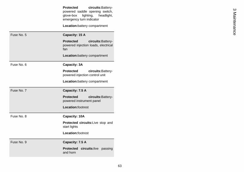
Protected circuits:Battery-powered saddle opening switch,glove-box lighting, headlight,emergency turn indicator
Location:battery compartment
Fuse No. 5 Capacity: 15 A
Protected circuits:Battery-powered injection loads, electricalfan
Location:battery compartment
Fuse No. 6 Capacity: 3A
Protected circuits:Battery-powered injection control unit
Location:battery compartment
Fuse No. 7 Capacity: 7.5 A
Protected circuits:Battery-powered instrument panel
Location:footrest
Fuse No. 8 Capacity: 10A
Protected circuits:Live stop andstart lights
Location:footrest
Fuse No. 9 Capacity: 7.5 A
Protected circuits:live passingand horn
63
3 Maintenance

Location:battery compartment
Fuse No. 10 Capacity: 7.5A
Protected circuits:Live injection,electrical fan remote controlantenna, injection loads remotecontrol
Location:footrest
Fuse No. 11 Capacity: 7.5A
Protected circuits:Live ECUparking lever, antitheft device,instrument panel, headlight remotecontrol, horn remote control
Location:footrest
Fuse No. 12 Capacity: 7.5A
Protected circuits:Live turnindicator, saddle opening switch,tail lights, panel lighting
Location:footrest
LIGHT BULBS TABLE
Low-beam bulb Type: HALOGEN (H1)
Power: 12V - 55W
Quantity: 1
64
3 M
aint
enan
ce
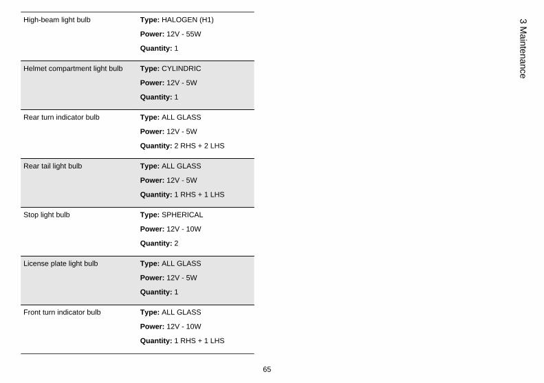
High-beam light bulb Type: HALOGEN (H1)
Power: 12V - 55W
Quantity: 1
Helmet compartment light bulb Type: CYLINDRIC
Power: 12V - 5W
Quantity: 1
Rear turn indicator bulb Type: ALL GLASS
Power: 12V - 5W
Quantity: 2 RHS + 2 LHS
Rear tail light bulb Type: ALL GLASS
Power: 12V - 5W
Quantity: 1 RHS + 1 LHS
Stop light bulb Type: SPHERICAL
Power: 12V - 10W
Quantity: 2
License plate light bulb Type: ALL GLASS
Power: 12V - 5W
Quantity: 1
Front turn indicator bulb Type: ALL GLASS
Power: 12V - 10W
Quantity: 1 RHS + 1 LHS
65
3 Maintenance
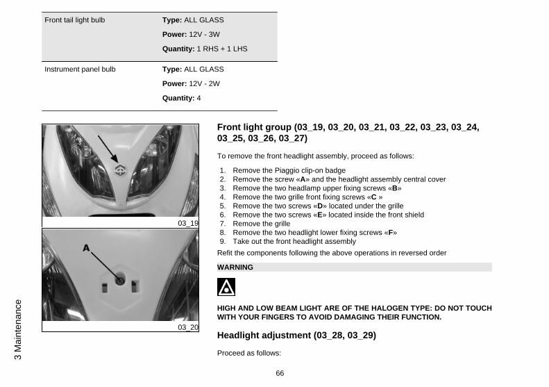
Front tail light bulb Type: ALL GLASS
Power: 12V - 3W
Quantity: 1 RHS + 1 LHS
Instrument panel bulb Type: ALL GLASS
Power: 12V - 2W
Quantity: 4
03_19
03_20
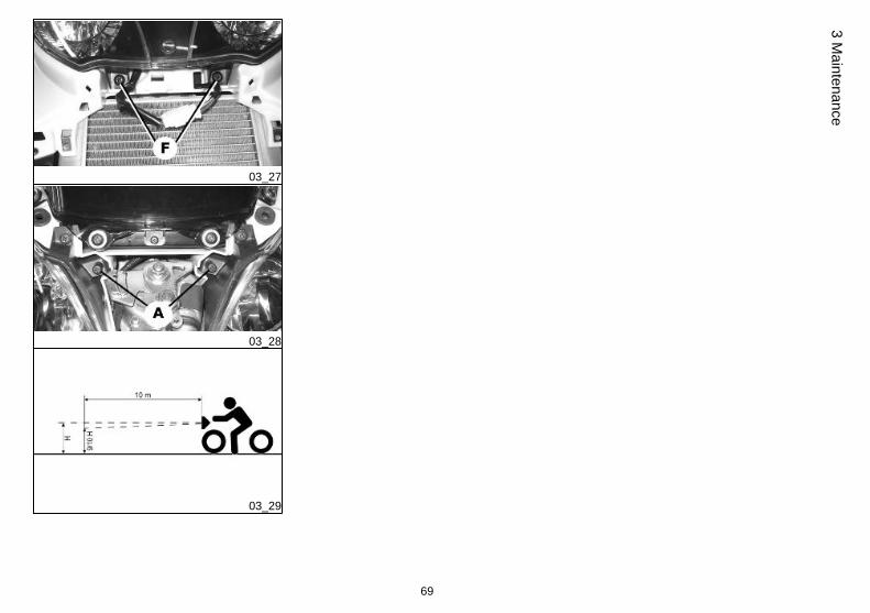
Front light group (03_19, 03_20, 03_21, 03_22, 03_23, 03_24,03_25, 03_26, 03_27)
To remove the front headlight assembly, proceed as follows:
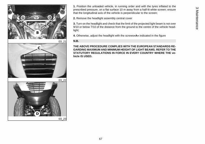
1. Remove the Piaggio clip-on badge2. Remove the screw «A» and the headlight assembly central cover3. Remove the two headlamp upper fixing screws «B»4. Remove the two grille front fixing screws «C »5. Remove the two screws «D» located under the grille6. Remove the two screws «E» located inside the front shield7. Remove the grille8. Remove the two headlight lower fixing screws «F»9. Take out the front headlight assembly
Refit the components following the above operations in reversed order
WARNING
HIGH AND LOW BEAM LIGHT ARE OF THE HALOGEN TYPE: DO NOT TOUCHWITH YOUR FINGERS TO AVOID DAMAGING THEIR FUNCTION.
Headlight adjustment (03_28, 03_29)
Proceed as follows:
66
3 M
aint
enan
ce
03_21
03_22
03_23
1. Position the unloaded vehicle, in running order and with the tyres inflated to theprescribed pressure, on a flat surface 10 m away from a half-lit white screen; ensurethat the longitudinal axis of the vehicle is perpendicular to the screen;
2. Remove the headlight assembly central cover
3. Turn on the headlight and check that the limit of the projected light beam is not over9/10 or below 7/10 of the distance from the ground to the centre of the vehicle head-light;
4. Otherwise, adjust the headlight with the screws«A» indicated in the figure
N.B.
THE ABOVE PROCEDURE COMPLIES WITH THE EUROPEAN STANDARDS RE-GARDING MAXIMUM AND MINIMUM HEIGHT OF LIGHT BEAMS. REFER TO THESTATUTORY REGULATIONS IN FORCE IN EVERY COUNTRY WHERE THE ve-hicle IS USED.
67
3 Maintenance

03_24
03_25
03_26
68
3 M
aint
enan
ce
03_27
03_28
03_29
69
3 Maintenance
03_30
03_31
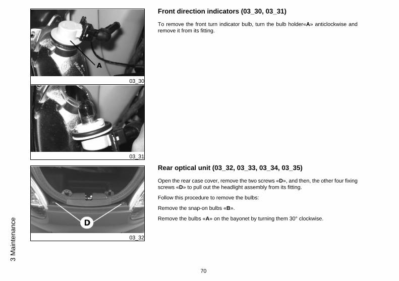
Front direction indicators (03_30, 03_31)
To remove the front turn indicator bulb, turn the bulb holder«A» anticlockwise andremove it from its fitting.
03_32
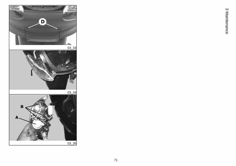
Rear optical unit (03_32, 03_33, 03_34, 03_35)
Open the rear case cover, remove the two screws «D», and then, the other four fixingscrews «D» to pull out the headlight assembly from its fitting.
Follow this procedure to remove the bulbs:
Remove the snap-on bulbs «B».
Remove the bulbs «A» on the bayonet by turning them 30° clockwise.
70
3 M
aint
enan
ce
03_33
03_34
03_35
71
3 Maintenance

03_36
03_37
Number plate light (03_36, 03_37)
Open the rear case and remove the rubber «A» shown in the figure without damagingthe plastic parts. Next, slide off the bulb holder.
Remove the bulb afterwards.
03_38
Helmet compartment lighting bulb (03_38)
Open the rear boot and insert a small plain slot screwdriver in the lateral notch todetach the snap-on glass "D", then replace the bulb.
72
3 M
aint
enan
ce
03_39
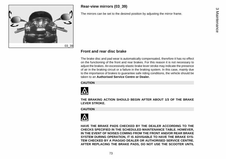
Rear-view mirrors (03_39)
The mirrors can be set to the desired position by adjusting the mirror frame.
Front and rear disc brake
The brake disc and pad wear is automatically compensated, therefore it has no effecton the functioning of the front and rear brakes. For this reason it is not necessary toadjust the brakes. An excessively elastic brake lever stroke may indicate the presenceof air in the braking circuit or a failure in the braking system. In this case, mainly dueto the importance of brakes to guarantee safe riding conditions, the vehicle should betaken to an Authorised Service Centre or Dealer.
CAUTION
THE BRAKING ACTION SHOULD BEGIN AFTER ABOUT 1/3 OF THE BRAKELEVER STROKE.
CAUTION
HAVE THE BRAKE PADS CHECKED BY THE DEALER ACCORDING TO THECHECKS SPECIFIED IN THE SCHEDULED MAINTENANCE TABLE. HOWEVER,IN THE EVENT OF NOISES COMING FROM THE FRONT AND/OR REAR BRAKESYSTEM DURING OPERATION, IT IS ADVISABLE TO HAVE THE BRAKE SYS-TEM CHECKED BY A PIAGGIO DEALER OR AUTHORISED SERVICE CENTRE.AFTER REPLACING THE BRAKE PADS, DO NOT USE THE SCOOTER UNTIL
73
3 Maintenance
YOU HAVE OPERATED THE BRAKE LEVER SEVERAL TIMES IN ORDER TOALLOW THE PLUNGERS TO SETTLE AND THE LEVER STROKE TO BE SET TOTHE CORRECT POSITION.
CAUTION
THE PRESENCE OF SAND, MUD, SNOW MIXED WITH SALT, ETC. ON THEROAD, CAN DRASTICALLY REDUCE THE DURATION OF THE BRAKE PADS. INORDER TO AVOID THIS, WE RECOMMEND WASHING THE VEHICLE FRE-QUENTLY WHEN RIDING IN THESE ROAD CONDITIONS.
Puncture
The vehicle is equipped with tubeless tyres (without inner tube). In the event of apuncture, contrary to the situation with a tyre with inner tube, the tyre deflates moreslowly, resulting in a greater steering safety. In the event of a puncture, it is admissibleto make an emergency repair using an "inflate and repair" spray can. For a final repair,take your vehicle to an Authorised Service Centre or Dealer. The replacement of atyre involves removing the wheel in question. Take your vehicle to an AuthorisedService Centre or Dealer for these operations.
CAUTION
TO USE THE "INFLATE AND REPAIR" SPRAY PROPERLY FOLLOW THE IN-STRUCTIONS ON THE PACKAGING.
74
3 M
aint
enan
ce

WARNING
THE WHEELS FITTED WITH TYRES SHOULD ALWAYS BE BALANCED. RIDINGTHE VEHICLE WITH VERY LOW TYRE PRESSURE OR WITH INCORRECTLYBALANCED TYRES CAN LEAD TO DANGEROUS STEERING VIBRATIONS.
Periods of inactivity
We recommend carrying out the following operations:
1. Clean the scooter thoroughly and then cover it with a canvas;
2. Be careful to rest the vehicle on its centre stand disabling the front suspensionlocking system;
3. With engine off and piston at the bottom dead centre, remove the spark plug, add1÷2 cc of oil through the opening (adding more oil may damage the engine). Operatethe starter button 1-2 times for roughly 1 second to turn the engine over slowly, theninsert the spark plug again;
4. Empty all fuel; spread antirust grease on the unpainted metal parts; keep the wheelslifted above the ground by resting the chassis on two wooden wedges;
5. For the battery, follow the procedures described in the «Battery» section.
Recommended productsAGIP CITY HI TEC 4T
Oil to lubricate flexible transmissions (throttle control)Oil for 4-stroke engines
Cleaning the vehicle
In order to soften the dirt and mud deposited on the painted surfaces, use a low pres-sure jet of water. Once softened, mud and dirt must be removed with a soft spongefor bodywork soaked in lots of water and "shampoo" (2-4% of car shampoo in water).
75
3 Maintenance

Then rinse abundantly with water, and dry with a shammy cloth. For the outside of theengine, use petroleum, a brush and clean cloths. Petroleum can damage paintwork.Remember that any polishing with silicone wax must always be preceded by washing
CAUTION
DETERGENTS CAN POLLUTE WATER. THE VEHICLE MUST BE WASHED AT AWASH STATION EQUIPPED WITH A SPECIAL WATER PURIFICATION SYSTEM.
CAUTION
PER IL LAVAGGIO DEL MOTORE E DEL VEICOLO É SCONSIGLIATO L'UTILIZ-ZO DELL'IDROPULITRICE; NEL CASO CHE NON SIA POSSIBILE EFFETTUARETALE OPERAZIONE IN UN ALTRO MODO, É NECESSARIO:• USARE SOLAMENTE IL GETTO A VENTAGLIO.
• NON AVVICINARE LA LANCIA A MENO DI 2 FT (60 CM).
• NON USARE ACQUA A TEMPERATURE SUPERIORI A 100° F (40°C).
• NON UTILIZZARE IL GETTO AD ALTA PRESSIONE.
• NON UTILIZZARE IL LAVAGGIO A VAPORE.
• NON INDIRIZZARE IL GETTO DIRETTAMENTE VERSO: IL MOTORE, I CA-BLAGGI ELETTRICI, LE FERITOIE DI RAFFREDDAMENTO DEL COPERCHIOTRASMISSIONE E DEL COPERCHIO CHIOCCIOLA.
CAUTION
NEVER WASH THE SCOOTER IN DIRECT SUNLIGHT, ESPECIALLY IN SUMMERWHEN THE BODYWORK IS STILL HOT AS THE SHAMPOO COULD DAMAGETHE PAINTWORK IF IT DRIES BEFORE BEING RINSED OFF. NEVER USE
76
3 M
aint
enan
ce
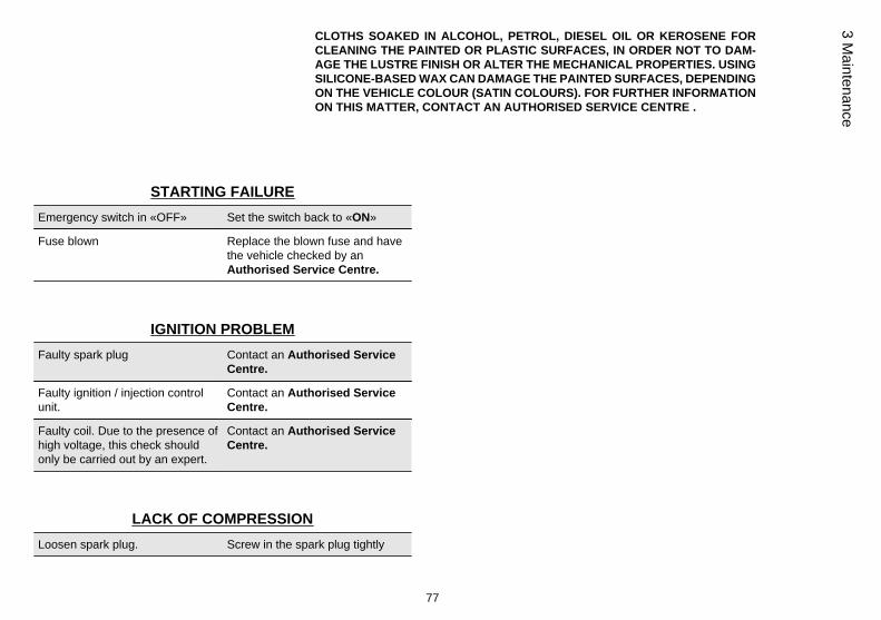
CLOTHS SOAKED IN ALCOHOL, PETROL, DIESEL OIL OR KEROSENE FORCLEANING THE PAINTED OR PLASTIC SURFACES, IN ORDER NOT TO DAM-AGE THE LUSTRE FINISH OR ALTER THE MECHANICAL PROPERTIES. USINGSILICONE-BASED WAX CAN DAMAGE THE PAINTED SURFACES, DEPENDINGON THE VEHICLE COLOUR (SATIN COLOURS). FOR FURTHER INFORMATIONON THIS MATTER, CONTACT AN AUTHORISED SERVICE CENTRE .
STARTING FAILUREEmergency switch in «OFF» Set the switch back to «ON»
Fuse blown Replace the blown fuse and havethe vehicle checked by anAuthorised Service Centre.
IGNITION PROBLEMFaulty spark plug Contact an Authorised Service
Centre.
Faulty ignition / injection controlunit.
Contact an Authorised ServiceCentre.
Faulty coil. Due to the presence ofhigh voltage, this check shouldonly be carried out by an expert.
Contact an Authorised ServiceCentre.
LACK OF COMPRESSIONLoosen spark plug. Screw in the spark plug tightly
77
3 Maintenance
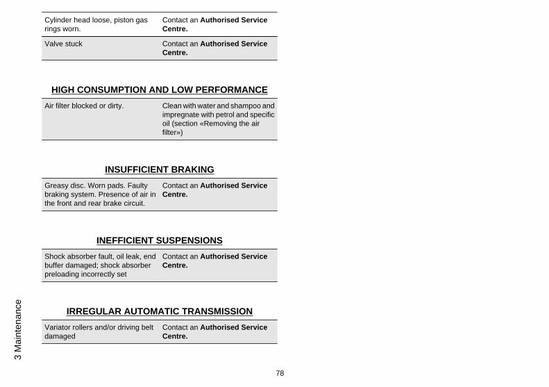
Cylinder head loose, piston gasrings worn.
Contact an Authorised ServiceCentre.
Valve stuck Contact an Authorised ServiceCentre.
HIGH CONSUMPTION AND LOW PERFORMANCEAir filter blocked or dirty. Clean with water and shampoo and
impregnate with petrol and specificoil (section «Removing the airfilter»)
INSUFFICIENT BRAKINGGreasy disc. Worn pads. Faultybraking system. Presence of air inthe front and rear brake circuit.
Contact an Authorised ServiceCentre.
INEFFICIENT SUSPENSIONSShock absorber fault, oil leak, endbuffer damaged; shock absorberpreloading incorrectly set
Contact an Authorised ServiceCentre.
IRREGULAR AUTOMATIC TRANSMISSIONVariator rollers and/or driving beltdamaged
Contact an Authorised ServiceCentre.
78
3 M
aint
enan
ce
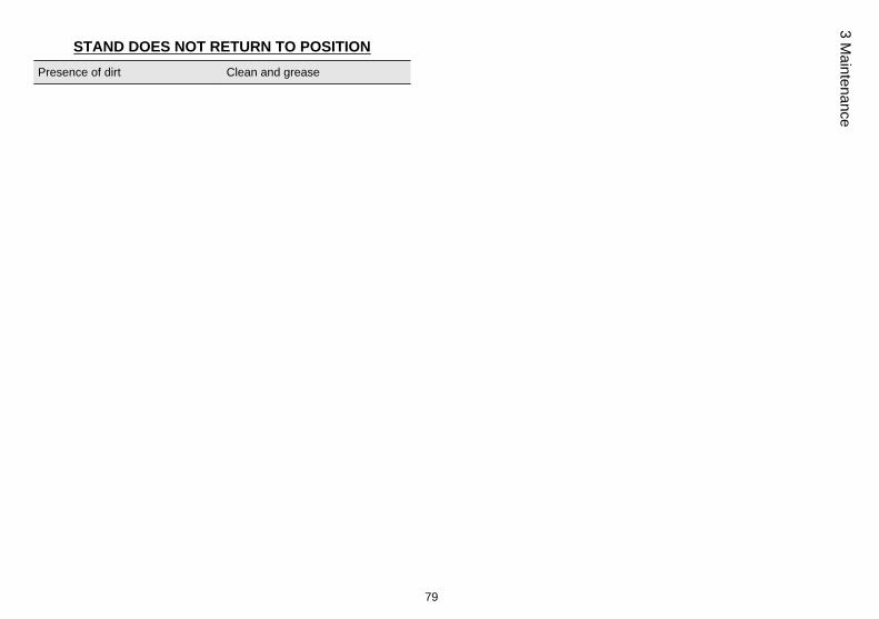
STAND DOES NOT RETURN TO POSITIONPresence of dirt Clean and grease
79
3 Maintenance

80
3 M
aint
enan
ce

MP3 250 i.e.
Chap. 04Technical data
81

04_01
MP3 250 I.E. TECHNICAL DATA
Electronic ignition inductive, high efficiencyintegrated with the injectionsystem, with variable timing andseparate HV coil.
Fuel supply throttle valve dia. 32 mm and singleinjector
Transmission With automatic expandable pulleyvariator with torque server, V belt,self-ventilating automaticcentrifugal dry clutch, gearreduction unit and transmission
82
4 Te
chni
cal d
ata
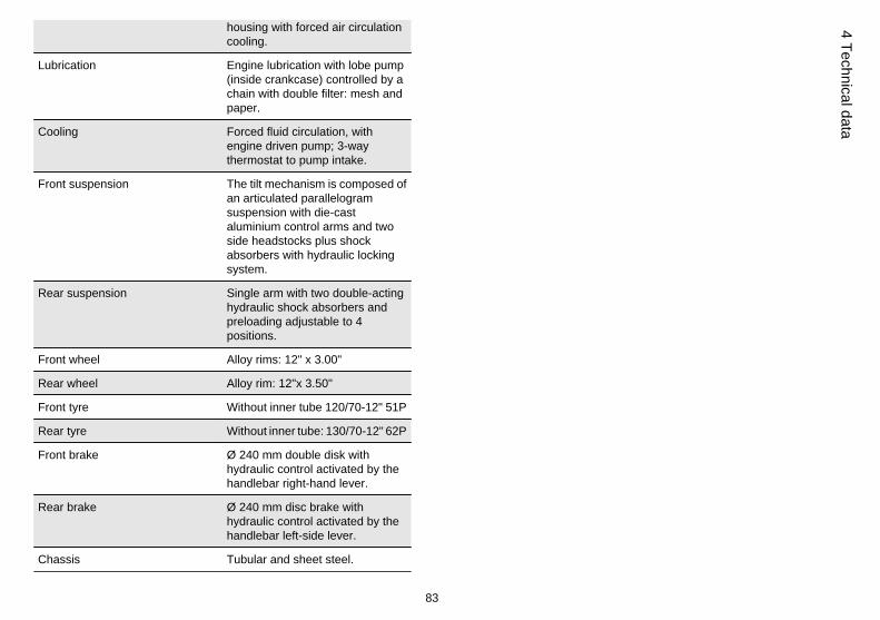
housing with forced air circulationcooling.
Lubrication Engine lubrication with lobe pump(inside crankcase) controlled by achain with double filter: mesh andpaper.
Cooling Forced fluid circulation, withengine driven pump; 3-waythermostat to pump intake.
Front suspension The tilt mechanism is composed ofan articulated parallelogramsuspension with die-castaluminium control arms and twoside headstocks plus shockabsorbers with hydraulic lockingsystem.
Rear suspension Single arm with two double-actinghydraulic shock absorbers andpreloading adjustable to 4positions.
Front wheel Alloy rims: 12" x 3.00"
Rear wheel Alloy rim: 12"x 3.50"
Front tyre Without inner tube 120/70-12" 51P
Rear tyre Without inner tube: 130/70-12" 62P
Front brake Ø 240 mm double disk withhydraulic control activated by thehandlebar right-hand lever.
Rear brake Ø 240 mm disc brake withhydraulic control activated by thehandlebar left-side lever.
Chassis Tubular and sheet steel.
83
4 Technical data

Kerb weight 224 ± 5 Kg
bearing 410 kg
Max. speed 125 km/h
Air filter Sponge impregnated with fuelmixture (50% SELENIA air filter oiland 50% unleaded petrol).
Fuel tank capacity Tank capacity: ~12 l (approximatevalue)
Fuel reserve ~ 2.0 l (approximate value)
Cooling circuit Capacity: ~ 2.0 l
Rear hub oil 250 cc
Exhaust muffler Twin three-way catalytic converter
MP3 250 I.E. ENGINE SPECIFICATIONS
Engine single-cylinder four stroke
Bore x stroke 72 x 60 mm
Cubic capacity 244.29 cm³
Compression ratio 10.5 - 11.5 : 1
Ignition advance (before TDC) variable (integrated into the ignitionsystem)
Spark plug CHAMPION RG 4 PHP
Valve clearance intake: 0.10 mmdischarge: 0.15 mm
Engine oil Capacity: 1.3 l (dry) ; 1.2 l (whenchanging oil and filter)
84
4 Te
chni
cal d
ata
04_02
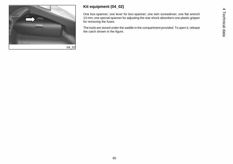
Kit equipment (04_02)
One box-spanner; one lever for box-spanner; one twin screwdriver; one flat wrench13 mm; one special spanner for adjusting the rear shock absorbers one plastic gripperfor removing the fuses.
The tools are stored under the saddle in the compartment provided. To open it, releasethe catch shown in the figure.
85
4 Technical data

86
4 Te
chni
cal d
ata
MP3 250 i.e.
Chap. 05Spare parts and
accessories
87

05_01
Warnings (05_01)
WARNING
TO PREVENT ACCIDENTS AND TO GUARANTEE PROPER STABILITY, PERFORM-ANCE AND SAFETY, RIDE THE VEHICLE VERY CAREFULLY WHEN IT IS FITTEDWITH ACCESSORIES OR WITH UNUSUAL LOADS.
WARNING
IT IS ALSO RECOMMENDED THAT "ORIGINAL PIAGGIO SPARE PARTS" BE USED,AS THESE ARE THE ONLY ONES OFFERING YOU THE SAME QUALITY GUARAN-TEE AS THOSE INITIALLY FITTED ON THE SCOOTER. THE USE OF NON-ORIGINALSPARE PARTS RENDERS THE WARRANTY VOID.
88
5 Sp
are
parts
and
acc
esso
ries

WARNING
PIAGGIO MARKETS ITS OWN LINE OF ACCESSORIES THAT ARE RECOGNISEDAND GUARANTEED FOR USE. IT IS THEREFORE ESSENTIAL, IN ORDER TOCHOOSE AND MOUNT THE ACCESSORIES CORRECTLY, TO CONTACT AN AU-THORISED DEALER OR SERVICE CENTRE. THE USE OF NON-ORIGINAL ACCES-SORIES MAY AFFECT THE STABILITY AND OPERATION OF YOUR VEHICLE ANDREDUCE SAFETY LEVELS WITH POTENTIAL RISKS FOR THE RIDER.
WARNING
NEVER RIDE THE SCOOTER EQUIPPED WITH ACCESSORIES (TOP BOX AND/ORWINDSHIELD) AT A SPEED HIGHER THAN 100 km/h.
THE SCOOTER CAN BE RIDDEN AT A HIGHER SPEED WITHOUT THE ACCESSO-RIES MENTIONED BEFORE WITHIN THE LIMITS ESTABLISHED BY LAW.
IF THERE SHOULD BE NOT-PIAGGIO ACCESSORIES INSTALLED, OR AN ABNOR-MAL LOAD, OR IF THE SCOOTER IS NOT IN A GENERALLY GOOD CONDITION, ORWHENEVER WEATHER CONDITIONS DEMAND IT, SPEED SHOULD BE REDUCEDFURTHER.
WARNING
BE EXTREMELY CAREFUL WHEN INSTALLING AND REMOVING THE MECHANI-CAL ANTITHEFT DEVICE ON THE VEHICLE (U-SHAPED PADLOCK, DISC BLOCK,ETC.).
MAINLY DUE TO THE PROXIMITY TO THE BRAKE PIPES, TRANSMISSIONS AND/OR ELECTRIC CABLES, AN INCORRECT INSTALLATION OR REMOVAL OF THEANTITHEFT DEVICE AS WELL AS LEAVING IT ON BEFORE STARTING THE VEHI-
89
5 Spare parts and accessories

CLE CAN SERIOUSLY DAMAGE ITS COMPONENTS AND AFFECT THE CORRECTFUNCTIONING OF THE VEHICLE AND HARM THE USER.
90
5 Sp
are
parts
and
acc
esso
ries

MP3 250 i.e.
Chap. 06Programmedmaintenance
91
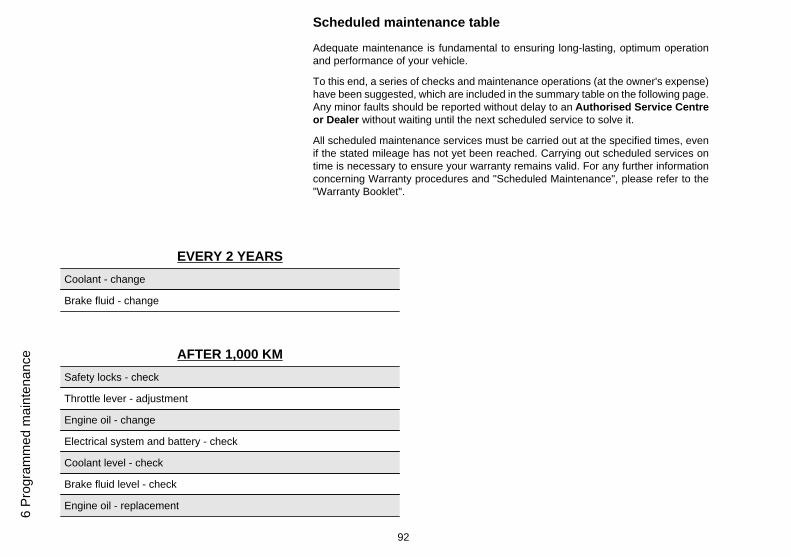
Scheduled maintenance table
Adequate maintenance is fundamental to ensuring long-lasting, optimum operationand performance of your vehicle.
To this end, a series of checks and maintenance operations (at the owner's expense)have been suggested, which are included in the summary table on the following page.Any minor faults should be reported without delay to an Authorised Service Centreor Dealer without waiting until the next scheduled service to solve it.
All scheduled maintenance services must be carried out at the specified times, evenif the stated mileage has not yet been reached. Carrying out scheduled services ontime is necessary to ensure your warranty remains valid. For any further informationconcerning Warranty procedures and "Scheduled Maintenance", please refer to the"Warranty Booklet".
EVERY 2 YEARSCoolant - change
Brake fluid - change
AFTER 1,000 KMSafety locks - check
Throttle lever - adjustment
Engine oil - change
Electrical system and battery - check
Coolant level - check
Brake fluid level - check
Engine oil - replacement
92
6 Pr
ogra
mm
ed m
aint
enan
ce
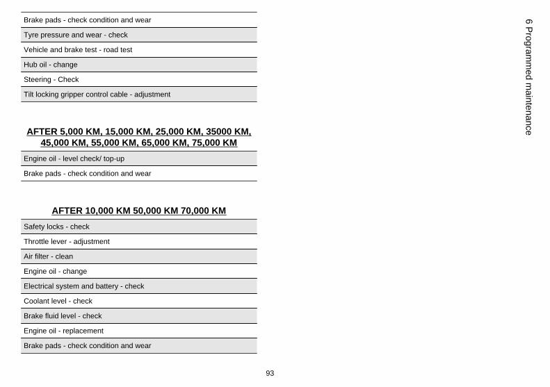
Brake pads - check condition and wear
Tyre pressure and wear - check
Vehicle and brake test - road test
Hub oil - change
Steering - Check
Tilt locking gripper control cable - adjustment
AFTER 5,000 KM, 15,000 KM, 25,000 KM, 35000 KM,45,000 KM, 55,000 KM, 65,000 KM, 75,000 KM
Engine oil - level check/ top-up
Brake pads - check condition and wear
AFTER 10,000 KM 50,000 KM 70,000 KMSafety locks - check
Throttle lever - adjustment
Air filter - clean
Engine oil - change
Electrical system and battery - check
Coolant level - check
Brake fluid level - check
Engine oil - replacement
Brake pads - check condition and wear
93
6 Programm
ed maintenance
Sliding block / variable speed rollers - change
Tyre pressure and wear - check
Vehicle and brake test - road test
Hub oil - check
Suspensions - check
Steering - Check
Centre stand - lubrication
Tilt locking gripper control cable - adjustment
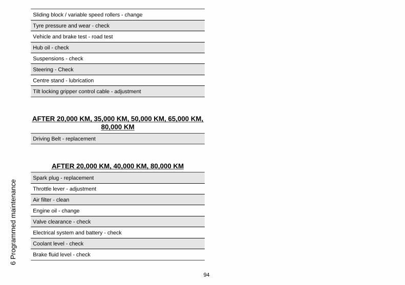
AFTER 20,000 KM, 35,000 KM, 50,000 KM, 65,000 KM,80,000 KM
Driving Belt - replacement
AFTER 20,000 KM, 40,000 KM, 80,000 KMSpark plug - replacement
Throttle lever - adjustment
Air filter - clean
Engine oil - change
Valve clearance - check
Electrical system and battery - check
Coolant level - check
Brake fluid level - check
94
6 Pr
ogra
mm
ed m
aint
enan
ce
Engine oil - replacement
Brake pads - check condition and wear
Sliding block / variable speed rollers - change
Tyre pressure and wear - check
Vehicle and brake test - road test
Hub oil - change
Suspensions - check
Steering - Check
Tilt locking gripper control cable - adjustment
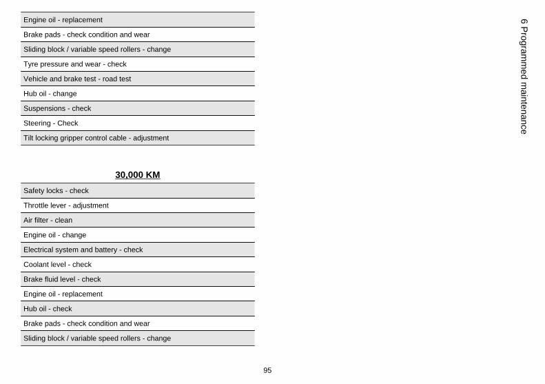
30,000 KMSafety locks - check
Throttle lever - adjustment
Air filter - clean
Engine oil - change
Electrical system and battery - check
Coolant level - check
Brake fluid level - check
Engine oil - replacement
Hub oil - check
Brake pads - check condition and wear
Sliding block / variable speed rollers - change
95
6 Programm
ed maintenance
Tyre pressure and wear - check
Vehicle and brake test - road test
Suspensions - check
Steering - Check
Tilt locking gripper control cable - adjustment
60,000 KMSpark plug - replacement
Throttle lever - adjustment
Air filter - clean
Engine oil - change
Valve clearance - check
Electrical system and battery - check
Coolant level - check
Brake fluid level - check
Engine oil - replacement
Hub oil - change
Brake pads - check condition and wear
Sliding block / variable speed rollers - change
Tyre pressure and wear - check
Vehicle and brake test - road test
Suspensions - check
96
6 Pr
ogra
mm
ed m
aint
enan
ce
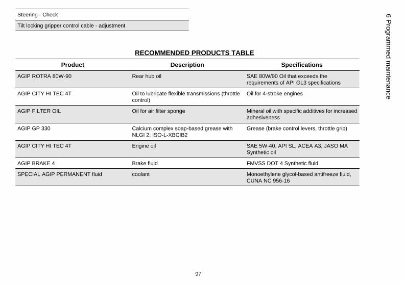
Steering - Check
Tilt locking gripper control cable - adjustment
RECOMMENDED PRODUCTS TABLEProduct Description Specifications
AGIP ROTRA 80W-90 Rear hub oil SAE 80W/90 Oil that exceeds therequirements of API GL3 specifications
AGIP CITY HI TEC 4T Oil to lubricate flexible transmissions (throttlecontrol)
Oil for 4-stroke engines
AGIP FILTER OIL Oil for air filter sponge Mineral oil with specific additives for increasedadhesiveness
AGIP GP 330 Calcium complex soap-based grease withNLGI 2; ISO-L-XBCIB2
Grease (brake control levers, throttle grip)
AGIP CITY HI TEC 4T Engine oil SAE 5W-40, API SL, ACEA A3, JASO MASynthetic oil
AGIP BRAKE 4 Brake fluid FMVSS DOT 4 Synthetic fluid
SPECIAL AGIP PERMANENT fluid coolant Monoethylene glycol-based antifreeze fluid,CUNA NC 956-16
97
6 Programm
ed maintenance

98
6 Pr
ogra
mm
ed m
aint
enan
ce

TABLE OF CONTENTS
AAir filter: 56
BBattery: 60Brake: 58, 73
CClock: 12
DDisc brake: 73Display: 13
EEngine oil: 50, 51Engine stop: 17
FFuel: 24Fuses: 61
HHeadlight: 66Horn: 15Hub oil: 52
IIdentification: 28Immobilizer: 18, 21Instrument panel: 10
KKey switch: 14Keys: 18
LLight switch: 16
MMaintenance: 13, 49, 91, 92Mirrors: 73
SSaddle: 22, 25–27Scheduled maintenance: 92Shock absorbers: 34Spark plug: 55Stand: 40Start-up: 17
TTank: 24Technical Data: 81Top box: 28Transmission: 41
Tyre pressure: 33Tyres: 54
99

The descriptions and illustrations given in this publication are not binding. While the basic features as described and illustrated in this manual remainunchanged, PIAGGIO - GILERA reserves the right, at any time and without being required to update this publication beforehand, to make any changesto components, parts or accessory supplies, which it considers necessary to improve the product or which are required for manufacturing or constructionreasons.
Not all versions shown in this publication are available in all Countries. The availability of individual versions should be confirmed with the official Piaggio sales network.
"© Copyright 2007 - PIAGGIO & C. S.p.A. Pontedera. All rights reserved. Reproduction of this publication in whole or in part is prohibited."
PIAGGIO & C. S.p.A. - After-Sales
V.le Rinaldo Piaggio, 23 - 56025 PONTEDERA (Pi)