Embed Size (px)
Citation preview

PIAGGIO WOULD LIKE TO THANK YOU
for choosing one of its products. We have prepared this manual to help you to get the very best from your vehicle. Please read it carefully before ridingthe vehicle for the first time. It contains information, tips and precautions for using your vehicle. It also describes features, details and devices to assureyou that you have made the right choice. We believe that if you follow our suggestions, you will soon get to know your new scooter and it will serve youwell for a long time to come. This booklet forms an integral part of the vehicle; should the vehicle be sold, it must be transferred to the new owner.
Fly 50 2T
Ed. 07_11/2012

The instructions given in this manual are intended to provide a clear, simple guide to using your vehicle; this booklet also details routine maintenanceprocedures and regular checks that should be carried out on the vehicle at an authorised Dealer or Service Centre. The booklet also containsinstructions for simple repairs. Any operations not specifically described in this booklet require the use of special tools and/or particular technicalknowledge: to carry out these operations, refer to any authorised Dealer or Service Centres.
2

Personal safety
Failure to completely observe these instructions will result in serious risk of personalinjury.
Safeguarding the environment
Sections marked with this symbol indicate the correct use of the vehicle to prevent dam-aging the environment.
Vehicle intactness
The incomplete or non-observance of these regulations leads to the risk of seriousdamage to the vehicle and sometimes even the invalidity of the guarantee.
The signs that you see on this page are very important. They are used to highlight partsof the booklet that should be read with particular care. The different symbols are usedto make each topic in the manual simple and quick to locate.
3

4

INDEX
VEHICLE...................................................................................... 7Dashboard................................................................................ 8Clock......................................................................................... 9Keyswitch.................................................................................. 10
Lockingthesteeringwheel....................................................... 10Releasingthesteeringwheel................................................... 10
Switchdirectionindicators.......................................................... 11Hornbutton................................................................................ 11Lightswitch................................................................................ 11Start-upbutton........................................................................... 12
Openingthesaddle................................................................. 13Keys.......................................................................................... 13Identification.............................................................................. 14Reartopboxopening................................................................... 14Bagclip...................................................................................... 15
USE.............................................................................................. 17Checks...................................................................................... 18Refuelling.................................................................................. 18Tyrepressure............................................................................. 20Runningin.................................................................................. 21Startinguptheengine.................................................................. 21Difficultstartup........................................................................... 22Stoppingtheengine.................................................................... 23Catalyticsilencer........................................................................ 24Automatictransmission.............................................................. 24Safedriving................................................................................ 25
MAINTENANCE........................................................................... 27Huboillevel................................................................................ 28Tyres......................................................................................... 29Sparkplugdismantlement.......................................................... 30Removingtheairfilter.................................................................. 31Secondaryairsystem................................................................. 32Intakeplug................................................................................. 32
Checkingthebrakeoillevel.......................................................... 33Battery....................................................................................... 34
Checkingtheelectrolytelevel................................................... 35Long periods of inactivity.......................................................... 36Fuses........................................................................................ 37Frontlightgroup.......................................................................... 39
Headlightadjustment.............................................................. 41Frontdirectionindicators............................................................. 41Rearopticalunit.......................................................................... 42Rear-viewmirrors....................................................................... 42Idleadjustment........................................................................... 43Frontdiscbrake.......................................................................... 43Reardrumbrake......................................................................... 44Puncture.................................................................................... 45delveicolo.................................................................................. 45Cleaningthevehicle.................................................................... 46
TECHNICALDATA....................................................................... 51Toolkit....................................................................................... 55
SPAREPARTSANDACCESSORIES........................................... 57Warnings................................................................................... 58
SCHEDULEDMAINTENANCE..................................................... 59Scheduledservicingtable........................................................... 60
5

6

Fly 50 2T
Chap. 01Vehicle
7

Dashboard (01_01)
A = Speedometer
B = Odometer
C = Fuel gauge
D = Front brake control lever
E = Turn indicator warning light
F = Mixer oil reserve warning light
G = High-beam warning light
H = Low fuel warning light
I = Low-beam/side lights warning light
L = High/low beam switch
M = Turn indicator switch
N = Horn button
P = Starter button
Q = Throttle grip
R = Rear brake control lever
S = Digital clock
8
1 Ve
hicl
e

01_01
01_02
Clock (01_02)
Hours and minutes are displayed in a 1 to 12, AM or PM, format on the instrumentpanel.Operating the function selection switch «T» month, day and seconds can be seenbesides hours and minutes. In order to adjust the above mentioned functions, operatebutton «U». The digital clock is powered by a battery (battery life is about 2 years); liftthe whole instrument panel to replace the battery. It is advisable to take your vehicleto an Authorised Service Centre for this operation.
WARNING
DEAD BATTERIES ARE HARMFUL TO THE ENVIRONMENT. THEY MUST DIS-POSED OF IN SUITABLE CONTAINERS AS PRESCRIBED BY THE REGULA-TIONS IN FORCE.
9
1 Vehicle

01_03
Keyswitch (01_03)
LOCK = Ignition disabled, extractable key, steering lock engaged front glove-boxlocked.
OFF = Ignition disabled, extractable key, steering lock disengaged, front glove-boxunlocked.
ON = Ready to start position, anti-theft device disabled, non-extractable key, glove-box unlocked.
Lockingthesteeringwheel
Turn the handlebar to the left (as far as it will go), turn the key to «LOCK» and removethe key.
CAUTION
DO NOT TURN THE KEY TO «LOCK» OR «KEY OFF» WHILE RIDING.
Releasingthesteeringwheel
Reinsert the key and turn it to «OFF».
CAUTION
DO NOT TURN THE KEY TO «LOCK» OR «KEY OFF» WHILE RIDING.
10
1 Ve
hicl
e

01_04
Switchdirectionindicators (01_04)
To set the left turn indicators flashing, move lever «B» to the left; to set the right turnindicators flashing, move it to the right. The lever automatically returns to the centralposition and the indicators remain on. To turn the indicators off, press the lever towardsthe switch.
01_05
Hornbutton (01_05)
Horn button «E»
Lightswitch (01_06)
0 = Low-beam and tail light
1 = High-beam and tail light
11
1 Vehicle

01_06
CAUTION
DO NOT PLACE, TRANSPORT OBJECTS AND/OR CLOTHES OVER THE FRONTHEADLIGHT ASSEMBLY, WHEN THE HEADLIGHT IS TURNED ON OR OFF.FAILURE TO FOLLOW THIS PRECAUTION MAY CAUSE OVERHEATING ANDTHE SUBSEQUENT FUSION OF THE GLASS.
01_07
Start-upbutton (01_07)
To start the engine, press the starter button, «P», after pulling either one of the twobrake levers.
12
1 Ve
hicl
e

01_08
Openingthesaddle (01_08)
Insert the key into the saddle lock «A», turn it anticlockwise and tip the saddle forward.
01_09
Keys (01_09)
The vehicle is supplied with two keys (one spare) which serve to start the engine andunlock the saddle compartment. The keys are accompanied by a tag marked with theidentification code to be quoted when ordering duplicates.
WARNING
WE RECOMMEND KEEPING THE DUPLICATE KEY TOGETHER WITH ITS CODEIN A SAFE PLACE AND NOT ON THE VEHICLE
13
1 Vehicle

01_10
01_11
Identification (01_10, 01_11)
The identification numbers consist of a prefix stamped on the chassis and on the en-gine, followed by a number. They must be quoted when ordering spare parts. Werecommend that you check that the prefix and chassis number stamped on the vehiclecorrespond with those in the vehicle documents.
CAUTION
PLEASE REMIND THAT ALTERING IDENTIFICATION REGISTRATION NUM-BERS CAN LEAD TO SERIOUS PENAL SANCTIONS (IMPOUNDING OF THEVEHICLE, ETC.).
Reartopboxopening
Turn the key to «OFF». Then press it. When the key is set to «LOCK», the glove-boxis locked.
14
1 Ve
hicl
e

01_12
Bagclip (01_12)
To use the retractable bag hook «B» located at the front end of the saddle, pull itforward lightly.
15
1 Vehicle

16
1 Ve
hicl
e

Fly 50 2T
Chap. 02Use
17

Checks
Before using the vehicle, check:
1.That the petrol tank and the oil reservoir are full.
2.Rear hub oil level.
3.That the tyres are properly inflated.
4.The correct functioning of headlights, rear light and turn indicators.
5.The correct functioning of front and rear brakes.
6.The fluid level in the brake pump reservoir.
02_01
Refuelling (02_01, 02_02)
Fill fuel tank «A» with unleaded gasoline. Minimum octane rating method 95.. Therider is informed when fuel is low by the fuel warning light on the instrument panel (seesection «The dashboard»).Fill engine oil tank «B» with new recommended engine oil. The rider is informed whenengine oil is low by the oil warning light on the instrument panel (see section «Thedashboard»).After this warning light goes on, at the next refuel(do not travel more than 150 km withthe warning light on).When the oil light comes on you are advised to top up the oiltank. When the key is turned to «ON» the oil warning light illuminates for a few sec-onds, indicating the light and oil warning circuit are working correctly.
If the warning light fails to illuminate, it is faulty. Contact an Authorized PiaggioService Center.
18
2 U
se

02_02
CAUTION
SHUT OFF THE ENGINE BEFORE REFUELLING WITH PETROL. PETROL ISHIGHLY FLAMMABLE. DO NOT LET PETROL SPILL FROM THE TANK OR WHILEREFUELLING
CAUTION
DO NOT BRING NAKED FLAMES OR CIGARETTES NEAR THE MOUTH OF THEFUEL TANK: FIRE HAZARD. ALSO AVOID INHALING HARMFUL VAPOURS.
IMPORTANT: NEVER EMPTY THE MIXER OIL RESERVOIR.
CAUTION
THE USE OF OILS AND SPARK PLUGS OTHER THAN THOSE RECOMMENDEDCAN SHORTEN THE LIFE OF THE ENGINE.
Recommended productseni i-Ride PG 2t
Synthetic based lubricant for low smoke 2-stroke engines and additives.API TC - JASO FC - ISO-L-EGD
Characteristicoil mixer tank
Plastic, capacity ~ 1.2 l
19
2 Use

Topping up mixer oil reservoir
Topping up oil reservoir: 0.5 ÷ 0.7 l
Fuel tank capacity
~ 7.2 litres (of which 1.5 l is reserve)
Tyrepressure
CAUTION
TYRE PRESSURE SHOULD BE CHECKED WHEN TYRES ARE COLD.INCOR-RECT TYRE PRESSURE CAUSES ABNORMAL TYRE WEAR AND MAKES RID-ING DANGEROUS.
TYRES MUST BE REPLACED WHEN THE TREAD REACHES THE WEAR LIMITSSET FORTH BY LAW.
CharacteristicFront tyre pressure
1.8 bar
Rear tyre pressure
2 bar
Rear wheel pressure (rider and passenger):
2.3 bar
20
2 U
se

02_03
Runningin (02_03)
WARNING
DURING THE FIRST 1000 KM DO NOT RIDE THE VEHICLE OVER 80% OF ITSMAXIMUM SPEED. AVOID TWISTING THE THROTTLE GRIP FULLY OR KEEP-ING A CONSTANT SPEED ALONG LONG SECTIONS OF ROAD. AFTER THEFIRST 1000 KM, GRADUALLY INCREASE SPEED UNTIL REACHING THE MAX-IMUM PERFORMANCE.
02_04
Startinguptheengine (02_04)
The vehicle is fitted with automatic transmission with a regulator and centrifugal clutch.Therefore always start the engine with the throttle at idle speed; to start-off from sta-tionary position, progressively twist the throttle grip.
The vehicle is equipped with a fuel valve and a starter which switch on automaticallyas soon as the engine is started.
In order to start the engine, it is necessary to pull either the rear brake lever «B » orthe front brake lever «C», before pressing the starting button, "A ", so as to disengagethe safety switches.
1: Put the scooter on its stand "E"; check that the rear wheel is off the ground.
2: Keep the throttle closed.
3: Insert the key into the ignition switch, "D", and turn to the ON position.
4: Push the starter button «A» after pulling the rear brake lever «B» or the front brakelever «C».
21
2 Use

CAUTION
DO NOT CARRY OUT THESE OPERATIONS IN CLOSED AREAS SINCE EX-HAUST GASES ARE TOXIC.
CAUTION
DUE TO THE HIGH TEMPERATURES THE CATALYTIC CONVERTER CANREACH, ALWAYS TAKE CARE, WHEN PARKING THE VEHICLE, THAT THE EX-HAUST DOES NOT COME INTO CONTACT WITH FLAMMABLE MATERIALS, TOAVOID SERIOUS BURNS.
02_05
Difficultstartup (02_05)
If there is a problem you can follow the instructions below:
1. Engine flooded. Place the vehicle on its centre stand and check that the rear wheelis off the ground. Open the throttle fully and press the starter button for five secondsand then stop for five seconds. If the engine does not start after a few attempts, letthe engine sit for a few minutes and then repeat the above operations. In any case donot operate the starter motor longer than 20" in an attempt to start the engine.
2. Battery or starter motor inefficiency. Put the scooter on its stand "E"; make surethat the rear wheel is off the ground, turn the key switch «D» to «ON» and use thekick-starter «F».
3. Empty fuel tank. After refuelling the scooter, start the engine by pressing the starterbutton «A» with the throttle at a minimum to provide maximum aspiration for the tap.If the vehicle fails to start even after carrying out the steps described above, contactan Authorised Service Centre.
22
2 U
se

CAUTION
ALWAYS PLACE THE VEHICLE ON ITS STAND BEFORE KICK STARTING.
WARNING
TAMPERING MAY CAUSE SERIOUS ENGINE MALFUNCTION.
02_06
Stoppingtheengine (02_06)
Stop acceleration, then turn the key switch «D» to «OFF » to stop the engine (ex-tractable key).
CAUTION
DUE TO THE HIGH TEMPERATURES THE CATALYTIC CONVERTER CANREACH, ALWAYS TAKE CARE, WHEN PARKING THE VEHICLE, THAT THE EX-HAUST DOES NOT COME INTO CONTACT WITH FLAMMABLE MATERIALS, TOAVOID SERIOUS BURNS.
23
2 Use
Catalyticsilencer
CAUTION
TAMPERING WITH THE CATALYTIC SILENCER MAY CAUSE SEVERE DAMAGETO THE ENGINE.
CAUTION
WHEN PARKING THE VEHICLE, DUE TO THE HIGH TEMPERATURES THE CAT-ALYTIC CONVERTER CAN REACH, ALWAYS BE CAREFUL THAT THE MUF-FLER DOES NOT COME INTO CONTACT WITH FLAMMABLE MATERIALS, TOAVOID SERIOUS BURNS.
CAUTION
DO NOT SHUT OFF THE ENGINE WHILE THE VEHICLE IS MOVING. UNBURNEDFUEL COULD ENTER THE CATALYTIC CONVERTER AND BURN, CAUSING THECONVERTER TO OVERHEAT AND POSSIBLY DESTROYING IT.
Automatictransmission
To ensure simple, pleasurable riding, the vehicle is equipped with automatic trans-mission with regulator and centrifugal clutch. The system is designed to give the bestpossible performance in terms of both acceleration and consumption, on level groundand uphill, thanks to the adjustments made to engine speed and transmitted torque.If you have to stop on an uphill slope (traffic lights, traffic jam, etc.) only use the braketo keep the vehicle still, leaving the motor running at idling speed. Using the motor tokeep the vehicle still can cause the clutch to overheat. This problem is due to the
24
2 U
se

friction of the clutch parts on the clutch bell. It is therefore recommended to avoidconditions of prolonged clutch slippage leading to clutch overheating (for example, aswell as the situation described above, riding uphill fully laden on steep slopes or start-ing off on slopes greater than 25%, etc.):
1. Do not continue riding in such conditions.
2. Let the clutch cool down with the motor at idling speed for a few minutes
Safedriving
WARNING
SOME SIMPLE TIPS ARE PROVIDED BELOW WHICH WILL ENABLE YOU TOUSE YOUR VEHICLE ON A DAILY BASIS MORE EASILY AND SAFELY.<
Your ability and your knowledge of the vehicle form the basis of safe riding. We rec-ommend trying out the vehicle in traffic-free zones to get to know your vehiclecompletely.ALWAYS DRIVE WITHIN YOUR LIMITS
1. Before riding off, remember to put on your helmet and fasten it correctly.
2. Reduce speed and ride cautiously on uneven roads.
3. Remember that after riding on a long stretch of wet road without using the brakes,the braking effect is initially lower. Under these conditions, it is a good idea to operatethe brakes from time to time.
4. Do not brake hard on a wet surface, on dirt tracks or on any slippery road surface.
25
2 Use

5. If you have to brake, use both brakes in order to divide the braking action betweenboth wheels.
6. Avoid starting off by mounting the vehicle while it is still resting on its stand. In anycase, the rear wheel should not be turning when it comes into contact with the ground,in order to avoid abrupt departures.
7. If the vehicle is used on roads covered with sand, mud, snow mixed with salt, etc.,clean the brake disc frequently with mild detergent in order to prevent abrasive sub-stances from building up within the holes, which can result in early wear of the brakepads.
8. Any elaboration that modifies the vehicle's performances, such as tampering withoriginal structural parts is strictly forbidden by law, and renders the vehicle not con-forming to the approved type and therefor dangerous to ride.
CAUTION
RIDING UNDER THE INFLUENCE OF ALCOHOL, DRUGS OR CERTAIN MEDI-CINES CAN BE EXTREMELY DANGEROUS FOR ONESELF AND FOR OTHERS.
CAUTION
ANY ELABORATION THAT MODIFIES THE VEHICLE'S PERFORMANCES, SUCHAS TAMPERING WITH ORIGINAL STRUCTURAL PARTS IS STRICTLY FORBID-DEN BY LAW, AND RENDERS THE VEHICLE NO LONGER CONFORMING TOTHE APPROVED TYPE AND DANGEROUS FOR RIDING.
26
2 U
se

Fly 50 2T
Chap. 03Maintenance
27

03_01
03_02
03_03
Huboillevel (03_01, 03_02, 03_03)
To check the hub oil level, proceed as follows:
1. Park the scooter on level ground and rest it on its stand.2. Unscrew the oil dipstick «A», dry it with a clean cloth and then reinsert it,
screwing it fully into place;3. Unscrew the dipstick again and check that the oil level just reaches the 2nd
notch from the bottom;4. Screw the dipstick back into place completely.
The screw «B» is the hub oil drainage plug.
CAUTION
RUNNING THE ENGINE WITH INSUFFICIENT LUBRICATION OR WITH THE IN-ADEQUATE LUBRICANTS ACCELERATES WEAR AND TEAR OF THE MOVINGPARTS AND CAN CAUSE IRRETRIEVABLE DAMAGE.
CAUTION
USED OILS CONTAIN SUBSTANCES HARMFUL TO THE ENVIRONMENT. FOROIL REPLACEMENT, CONTACT AN AUTHORISED SERVICE CENTRE WHICH ISEQUIPPED TO DISPOSE OF USED OILS IN AN ENVIRONMENTALLY FRIENDLYAND LEGAL WAY.
N.B.
THE NOTCHES ON THE HUB OIL LEVEL DIPSTICK, EXCEPT THE ONE INDI-CATING THE MAXIMUM AND MINIMUM LEVEL, REFER TO OTHER MODELS BYTHE MANUFACTURER AND HAVE NO SPECIFIC FUNCTION FOR THIS MODEL.
Recommended productsAGIP GEAR SAE 80W-90
28
3 M
aint
enan
ce
Lubricant for gearboxes and transmissions.API GL-4
CharacteristicRear hub oil
Quantity: approx. 85 cc
03_04
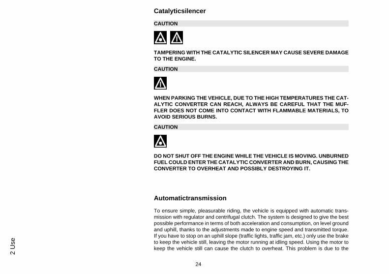
Tyres (03_04)
Periodically check the inflation pressure of each tyre (when cold).Tyres are fitted with wear indicators; tyres should be replaced as soon as these indi-cators become visible on the tyre tread. Also check that the tyres do not show signsof splitting at the sides or irregular tread wear; If this occurs, go to an authorised work-shop or at least a workshop adequately equipped to remove and refit tyres.
CAUTION
TYRE PRESSURE SHOULD BE CHECKED WHEN TYRES ARE COLD.INCOR-RECT TYRE PRESSURE CAUSES ABNORMAL TYRE WEAR AND MAKES RID-ING DANGEROUS.
TYRES MUST BE REPLACED WHEN THE TREAD REACHES THE WEAR LIMITSSET FORTH BY LAW.
CharacteristicFront tyre pressure
1.8 bar
Rear tyre pressure
2 bar
29
3 Maintenance

Rear wheel pressure (rider and passenger):
2.3 bar
03_05
03_06
Sparkplugdismantlement (03_05, 03_06)
After loosening the fixing screws, remove door «A». Detach the spark plug cap andremove the spark plug using the box-spanner provided. To refit the spark plug, driveit in by hand and with the correct inclination, then tighten using the box-spanner. Whenrefitting the door, follow the removal operations in the reverse order, minding the toptooth on the central cover.
CAUTION
FOLLOW THESE PROCEDURES VERY CAREFULLY TO AVOID ANY SEVEREDAMAGE THAT MAY BE CAUSED BY THE VERY POWERFUL IGNITION SYS-TEM.
CAUTION
THE SPARK PLUG MUST BE REMOVED WHEN THE ENGINE IS COLD.USING IGNITION ELECTRONIC CENTRAL UNITS OR SPARK PLUGS OTHERTHAN THE TYPES PRESCRIBED (SEE «TECHNICAL DATA» SECTION) CANCAUSE SERIOUS DAMAGE TO THE ENGINE.
Characteristicrecommended spark plug:
CHAMPION RN3C
Electrode gap
30
3 M
aint
enan
ce

0.6 ÷ 0.7 mm
03_07
03_08
Removingtheairfilter (03_07, 03_08)
After removing the spark plug access door, remove the side fairing loosening the 3fixing screws «A». Remove the air-box cover «D» after loosening the 5 fixing screws«C», and then extract the filter. Wash with soap, then dry with compressed air andhence soak in a 50% oil-petrol mixture. Squeeze, let dry and refit.
CAUTION
IN CASE OF RIDING ON DUSTY ROADS IT IS ADVISABLE TO CLEAN THE AIRFILTER MORE FREQUENTLY THAN INDICATED IN THE RELEVANT CHAPTERON SCHEDULED MAINTENANCE.
Recommended productsAGIP FILTER OIL
Special product for the treatment of foam filters.-
31
3 Maintenance
03_09
03_10
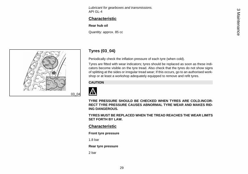
Secondaryairsystem (03_09, 03_10)
After removing the spark plug cap, remove the RHS fairing, by loosening the threefixing screws «B» shown in the figure.
Remove the SAS aluminium cover fixing screws «A». Detach the metal hose from itsrubber housing on the cover, without detaching it from the cover/bellow. Hence removeplate and plastic cover, extract the sponge and wash it with soap. Dry with compressedair before refitting, ensuring to correctly positioning the plate in the housing machinedon the plastic and aluminium covers. Whenever removing the part, always replace theO-ring located on the special housing on the cover.
03_11
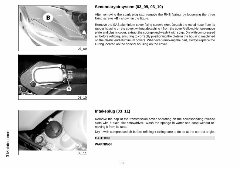
Intakeplug (03_11)
Remove the cap of the transmission cover operating on the corresponding releaseslots with a plain slot screwdriver. Wash the sponge in water and soap without re-moving it from its seat.Dry it with compressed air before refitting it taking care to do so at the correct angle.
CAUTION
WARNING!
32
3 M
aint
enan
ce

SHOULD THERE BE ANY PROBLEMS WHEN ADJUSTING IDLE SPEED, IT MAYBE NECESSARY TO ADJUST EXHAUST GASES (CO) TOO. TURN TO AN AU-THORISED PIAGGIO SERVICE CENTRE TO CARRY OUT THESE OPERATIONS.
03_12
03_13
Checkingthebrakeoillevel (03_12, 03_13)
The brake fluid reservoir is equipped with a sight glass «A» made of transparent ma-terial; the quantity of liquid contained in the sight glass indicates the level of liquid inthe reservoir.
When the sight glass «A» is full, the level inside the reservoir exceeds the MIN level;when it is partially full, the level drops to the MIN level; when it is fully empty, the levelof fluid in the reservoir is below the MIN level.
The brake fluid level may fall due to wear on the brake pads. In case the pad wear isbelow the minimum mark, contact an Authorised Service Centre to have the brakingsystem thoroughly checked. If you need to top up the level, follow the steps listedbelow. Unscrew the 2 screws «B», remove the reservoir cap «C » and pour in therequired quantity of fluid (the brake fluid level must be above minimum). Place thehandlebar in the riding position and pay attention not to tilt the vehicle in order to keepthe brake fluid reservoir in horizontal position when checking the fluid level.
CAUTION
TOP-UPS SHOULD ONLY BE CARRIED OUT WITH DOT4 CLASSIFIED BRAKEFLUID.
33
3 Maintenance

WARNING
IN NORMAL CLIMATIC CONDITIONS IT IS ADVISABLE TO REPLACE THEABOVE-MENTIONED FLUID EVERY 2 YEAR. NEVER USE BRAKE FLUID CON-TAINED IN CONTAINERS WHICH ARE ALREADY OPEN OR PARTIALLY USED.
CAUTION
THE BRAKING CIRCUIT FLUID IS HIGHLY CORROSIVE. THEREFORE, WHENTOPPING UP, AVOID LETTING IT COME INTO CONTACT WITH THE PAINTEDPARTS OF THE VEHICLE. THE BRAKING CIRCUIT FLUID IS HYGROSCOPIC,THAT IS, IT ABSORBS HUMIDITY FROM THE SURROUNDING AIR. IF MOISTURECONTAINED IN THE BRAKE FLUID EXCEEDS A CERTAIN VALUE, THIS WILLRESULT IN INEFFICIENT BRAKING.
03_14
Battery (03_14)
Lift the saddle forward to access the battery then remove access door to the batteryby unscrewing the star-shaped screws as shown in the picture.
The battery is the electrical device that requires the most frequent attention and themost thorough maintenance.
WARNING
USED BATTERIES ARE HARMFUL FOR THE ENVIRONMENT. COLLECTIONAND DISPOSAL SHOULD BE CARRIED OUT IN COMPLIANCE WITH REGULA-TIONS IN FORCE.
34
3 M
aint
enan
ce

CAUTION
ELECTROLYTE CONTAINS SULPHURIC ACID: AVOID CONTACT WITH EYES,SKIN AND CLOTHES. IN CASE OF ACCIDENTAL CONTACT, RINSE WITH ABUN-DANT WATER AND CONSULT A DOCTOR.
CAUTION
IN ORDER TO AVOID DAMAGING THE ELECTRICAL SYSTEM, NEVER DISCON-NECT THE WIRING WHILE THE ENGINE IS RUNNING. DO NOT TIP THE VEHICLETOO MUCH IN ORDER TO AVOID DANGEROUS LEAKAGE OF THE BATTERYELECTROLYTE.
Checkingtheelectrolytelevel
The electrolyte level, which should be checked regularly, must always be at the max-imum level. To reach this level, use only distilled water. Should it become necessaryto top up the battery with water too frequently, check the vehicle's electrical systembecause the battery is being overloaded, causing it to lose power quickly.
CAUTION
ELECTROLYTE CONTAINS SULPHURIC ACID: AVOID CONTACT WITH EYES,SKIN AND CLOTHES. IN CASE OF ACCIDENTAL CONTACT, RINSE WITH ABUN-DANT WATER AND CONSULT A DOCTOR.
35
3 Maintenance

Long periods of inactivity
Battery performance will be poor if the vehicle is not used for a long time. This is theresult of the natural phenomenon of battery discharging, and may be due to residualabsorption by vehicle components with constant power consumption. Poor batteryperformance may also be due to environmental conditions and the cleanliness of thepoles. In order to avoid difficult starts and/or irreversible damage to the battery, followany of these steps:
- At least once a month start the engine and run it slightly above idle speed for 10-15minutes. This keeps all the engine components, as well as the battery, in good workingorder.
- Take your vehicle to a garage (as indicated in the «Vehicle not used for extendedperiods» section) to have the battery removed. Have the battery cleaned, chargedfully and stored in a dry, ventilated place. Recharge at least once every twomonths.
N.B.
THE BATTERY MUST BE CHARGED WITH A CURRENT EQUAL TO 1/10 OF THERATED CAPACITY OF THE BATTERY AND FOR NOT LONGER THAN 10 HOURS.CONTACT AN AUTHORISED SERVICE CENTRE TO CARRY OUT THIS OPERA-TION SAFELY. WHEN REFITTING THE BATTERY MAKE SURE THE LEADS ARECORRECTLY CONNECTED TO THE TERMINALS.
WARNING
DO NOT DISCONNECT THE BATTERY CABLES WITH THE ENGINE RUNNING,THIS CAN CAUSE IRREPARABLE DAMAGE TO THE VEHICLE'S ELECTRONICCONTROL UNIT.
36
3 M
aint
enan
ce

WARNING
USED BATTERIES ARE HARMFUL FOR THE ENVIRONMENT. COLLECTIONAND DISPOSAL SHOULD BE CARRIED OUT IN COMPLIANCE WITH REGULA-TIONS IN FORCE.
03_15
Fuses (03_15)
The electrical system is protected by a plug fuse «B» located to the left of the batterycompartment. The ignition system, headlight and the rear light are not fuse-protected.Before replacing a blown fuse, find and solve the problem that caused it to blow. Donot substitute the fuse with any alternative form of conductor
CAUTION
IN ORDER TO AVOID DAMAGING THE ELECTRICAL SYSTEM, NEVER DISCON-NECT THE WIRING WHILE THE ENGINE IS RUNNING. DO NOT TIP THE VEHICLETOO MUCH IN ORDER TO AVOID DANGEROUS LEAKAGE OF THE BATTERYELECTROLYTE.
Electric characteristicFuse
Fuse valve: 7.5A
37
3 Maintenance

LIGHT BULBS TABLEHigh/low beam light bulb Type: Spherical
Power: 12V 35/35W
Quantity: 1
Front side light bulb Type: All glass
Power: 12V 5W
Quantity: 1
Front turn indicator light bulb Type: Spherical
Power: 12V - 10W
Quantity: 1 RHS + 1 LHS
Rear turn indicator light bulb Type: Spherical
Power: 12V - 10W
Quantity: 1 RHS + 1 LHS
Stop and tail light bulb Type: Spherical
Power: 12V 21/5W
Quantity: 1
12V - 2W warning light bulbs Type: All glass
Function: Turn indicators
Quantity: 2
Pilot light bulbs 12V - 1,2W Type: BAYONET
38
3 M
aint
enan
ce

Function: Lights, high beams,reserve level, reserve oil mixer
Quantity: 4
Instrument panel lighting bulbs Type: All glass
Power: 12V 1.2W
Quantity: 3
Frontlightgroup (03_16, 03_17)
To access the headlight bulbs, remove the front of the handlebar cover, as follows:
1) Remove the rear-view mirrors; for this operation follow the instructions describedand illustrated in the «Rear-view mirrors» section.
2) Unscrew the 3 screws holding the handlebar cover. The front central one «B» andthe rear 2 «C». Once this is done, the handlebar cover can be removed.
3) Remove the handlebar cover to access the headlight and the bulbs.
N.B.
IF MISTING IS NOTICED ON THE INSIDE OF THE HEADLAMP GLASS, THISDOES NOT INDICATE A FAULT AND IS ATTRIBUTABLE TO HUMIDITY AND/ORTO LOW TEMPERATURES.
THE PHENOMENON SHOULD QUICKLY DISAPPEAR WHEN THE LIGHT ISSWITCHED ON.
THE PRESENCE OF DROPS OF WATER, ON THE OTHER HAND, COULD INDI-CATE THAT WATER IS INFILTRATING. CONTACT THE AFTER-SALES SERVICENETWORK.
Electric characteristicBulbs
39
3 Maintenance

1 12V35/35W bulb for high- and low-beam light
1 12V-5W bulb for side light
03_16
03_17
CAUTION
DO NOT PLACE, TRANSPORT OBJECTS AND/OR CLOTHES OVER THE FRONTHEADLIGHT ASSEMBLY, WHEN THE HEADLIGHT IS TURNED ON OR OFF.FAILURE TO FOLLOW THIS PRECAUTION MAY CAUSE OVERHEATING ANDTHE SUBSEQUENT FUSION OF THE GLASS.
40
3 M
aint
enan
ce

03_18
03_19
Headlightadjustment (03_18, 03_19)
Proceed as follows:
1. Place the vehicle in running order and with the tyres inflated to the prescribed pres-sure, on a flat surface 10 m away from a white screen situated in a shaded area,making sure that the longitudinal axis of the vehicle is perpendicular to the screen;
2. Turn on the headlight and check that the borderline of the projected light beam onthe screen is no higher than 9/10 or lower than 7/10 of the distance from the groundto the centre of the vehicle's headlamp;
3. If otherwise, adjust the right headlight with screw «A».
N.B.
THE ABOVE PROCEDURE COMPLIES WITH THE EUROPEAN STANDARDS RE-GARDING MAXIMUM AND MINIMUM HEIGHT OF LIGHT BEAMS. REFER TO THESTATUTORY REGULATIONS IN FORCE IN EVERY COUNTRY WHERE THE VE-HICLE IS USED.
03_20
Frontdirectionindicators (03_20)
In order to replace the front turn indicator bulbs remove the light taking off the retainingscrews, then remove the bulb holder form its support; gently turn the bulb around 30ºand remove it. Follow the process in reverse order to refit.
41
3 Maintenance

03_21
Rearopticalunit (03_21)
In order to reach the rear light bulb, remove the 2 «D» retaining screws. Doing so it ispossible to access also the turn indicator bulbs. Gently push and turn the bulb about30° and then remove it. To refit follow the same steps but in reverse order.
N.B.
IF MISTING IS NOTICED ON THE INSIDE OF THE HEADLAMP GLASS, THISDOES NOT INDICATE A FAULT AND IS ATTRIBUTABLE TO HUMIDITY AND/ORTO LOW TEMPERATURES.
THE PHENOMENON SHOULD QUICKLY DISAPPEAR WHEN THE LIGHT ISSWITCHED ON.
THE PRESENCE OF DROPS OF WATER, ON THE OTHER HAND, COULD INDI-CATE THAT WATER IS INFILTRATING. CONTACT THE AFTER-SALES SERVICENETWORK.
Rear-viewmirrors (03_22)
The mirrors can be set to the desired position by adjusting the mirror frame.
03_22
To remove the rear-view mirror rotate the rear-view mirror support rod clockwise.
42
3 M
aint
enan
ce

03_23
Idleadjustment (03_23)
The idle speed is adjusted by means of the idle speed adjuster screw «A» located onthe carburettor.To do this, proceed as shown in the diagram. Turn the register for adjusting the clear-ance of the throttle control transmission «B», then replace the rubber protection cap.Adjust the idle speed with the rear wheel off the ground (vehicle on stand) and with awarm engine. Turn the knob-type head screw in or out until the engine idles smoothly(around 1700÷1900 rpm.), i.e. without the rear wheel being moved by the en-gine.If adjustment still proves difficult, contact an Authorised Piaggio Service Centre tohave the level of CO when idling fixed (carbon monoxide emissions).
CAUTION
WHEN ADJUSTING IDLE SPEED, BE CAREFUL NOT TO TOUCH HOT PARTS OFTHE ENGINE TO AVOID BURNS.
03_24
Frontdiscbrake (03_24)
The brake disc and pad wear is automatically compensated, therefore it has no effecton the functioning of the front and rear brakes. For this reason it is not necessary toadjust the brakes. An excessively elastic brake lever stroke may indicate the presenceof air in the braking circuit or an irregular brake operation. In this case, particularlyconsidering the importance of the brakes in terms of safety, it is strongly recommendedthat you take the vehicle to an Authorised Service Centre as soon as possible forthe appropriate checks.
43
3 Maintenance

WARNING
CHECK BRAKE PADS FOR WEAR ON A REGULAR BASIS (AS INDICATED INTHE SCHEDULE MAINTENANCE TABLES). IF THE THICKNESS OF ONE ORBOTH PADS IS IN THE REGION OF 1.5 MM, BOTH PADS MUST BE CHANGED.IT IS RECOMMENDED TO CARRY OUT THIS OPERATION AT AN AUTHORISEDSERVICE CENTRE AS SOON AS POSSIBLE.
AFTER FITTING NEW BRAKE PADS DO NOT USE THE VEHICLE UNTIL YOUHAVE ACTIVATED THE BRAKE LEVER REPEATEDLY TO POSITION THE PADSAND RESTORE THE LEVER STROKE TO ITS CORRECT POSITION.
CAUTION
BRAKING SHOULD BEGIN AFTER ABOUT 1/3 OF THE BRAKE LEVER STROKE.
03_25
Reardrumbrake (03_25)
Operate adjusting nut «B» and loosen lock nut «A» shown in the figure. Note thatwhen the throttle is in idle the wheel should rotate free. After the adjustment, screwlock nut «A».
CAUTION
BRAKING SHOULD BEGIN AFTER ABOUT 1/3 OF THE BRAKE LEVER STROKE.
44
3 M
aint
enan
ce

03_26
Puncture (03_26)
The vehicle is equipped with Tubeless tyres. When there is a puncture, Tubeless tyres- unlike tyres with inner tubes - go flat very slowly. This offers greater riding safety. Atyre that goes flat very slowly can be repaired with an "Inflate and Repair" spray. Tyresshould be later fully repaired or replaced at an Authorised Service Centre.
03_27
delveicolo (03_27)
We recommend carrying out the following operations:1. General cleaning of the vehicle.
2. With the engine off and the piston at the bottom dead centre position, remove thespark plug, and pour 1-2 cm³ of recommended oil through its hole. Press the enginestart pedal 3 or 4 times letting the engine perform a few revolutions slowly, then replacethe spark plug.
45
3 Maintenance

3. Drain up all the vehicle fuel; spread antirust grease on the uncoated metal parts;keep the wheels off the ground, by resting the chassis on two wooden wedges.
4. For the battery, follow the procedures described in the «Battery» section.
5. Drain the petrol from the carburettor float chamber through the bleed cap.
Recommended productseni i-Ride PG 5W-40
Synthetic based lubricant for high-performance four-stroke engines.JASO MA, MA2 - API SL - ACEA A3
Cleaningthevehicle
Use a low pressure jet of water to soften the caked dirt and mud deposited on thepainted surfaces. Once softened, sponge off mud and dirt using a car body spongesoaked in a car body shampoo and water solution (2-4% of car shampoo in water).Then rinse with abundant water, and dry with a shammy cloth. For the engine exterior,use petrol, a brush and clean cloths. Petrol can damage paintwork. Remember thatany polishing with silicone wax must always be preceded by washing.
WARNING
To avoid the appearance of oxidations, wash the vehicle every time it is used incertain areas or in special conditions of:
· Environmental / seasonal conditions: use of salt, de-icer chemical products onthe road in winter.
· Air pollution: city and/or industrial areas.
· Salinity and humidity of the atmosphere: marine areas, hot and wet weather.
46
3 M
aint
enan
ce

WARNING
. Prevent deposits from remaining on the bodywork, industrial and pollutantresidual dust, tar spots, dead insects, bird droppings, etc.
· Do not park the vehicle under the trees. In some seasons, in fact, residues,resins, fruits or leaves may fall from the trees, containing chemicals that areharmful to the paintwork.
CAUTION
DETERGENTS POLLUTE WATER. THEREFORE THE VEHICLE SHOULD BEWASHED IN AN AREA EQUIPPED FOR THE COLLECTION AND PURIFICATIONOF THE LIQUIDS USED.
WARNING
NEVER WASH THE VEHICLE UNDER DIRECT SUNLIGHT, ESPECIALLY IN SUM-MER WHEN THE BODYWORK IS STILL HOT, AS THE CAR SHAMPOO MAY DRYBEFORE BEING RINSED OFF, AND COULD DAMAGE THE PAINTWORK. NEVERUSE RAGS SOAKED IN PETROL OR DIESEL OIL TO CLEAN THE PAINTED ORPLASTIC SURFACES, IN ORDER TO PREVENT THEM LOSING THEIR SHINEAND MECHANICAL CHARACTERISTICS.
WARNING
WHEN WASHING THE ENGINE WITH A HIGH-PRESSURE WATER JET:
• ONLY USE FAN SPRAY JETS.
47
3 Maintenance

• DO NOT PLACE THE NOZZLE CLOSER THAN 60 CM.• DO NOT USE WATER AT TEMPERATURES OVER 40° C.• DO NOT DIRECT THE JETS DIRECTLY TO CARBURETTOR, WIRINGS, SLOTDIFFUSERS ON THE TRANSMISSION COVER AND SCROLL COVER.
DIFFICULT STARTINGNo fuel in tank Refuel
Filters, jets or carburettor bodydirty or clogged.
Contact an Authorised ServiceCentre.
Insufficient battery charge Kick-start. Recharge the battery.
IGNITION PROBLEMS
No spark from spark plug. Due tothe presence of high voltage, thischeck should only be carried out byan expert.
Check that the electrodes areproperly adjusted (0.7÷ 0.8 mm).Check that the electrodes areclean (use pure petrol and a metalbrush or an emery cloth). Checkthe spark plug insulator: Replacethe spark plug if the insulator iscracked or broken. If the spark plugis in good conditions, contact anAuthorised Service Centre.
48
3 M
aint
enan
ce

LACK OF COMPRESSION
Spark plug loose. Loose cylinderhead, worn piston retaining rings.
Contact an Authorised ServiceCentre.
HIGH CONSUMPTION AND LOW PERFORMANCEAir filter blocked or dirty. Clean with water and shampoo and
impregnate with petrol and specificoil («Air filter removal» section)
INEFFICIENT BRAKINGOil on drum or disc. Worn Pads/Shoes
Contact an Authorised ServiceCentre
incorrect rear brake adjustment Adjust
INEFFICIENT SUSPENSIONOil leak; worn limit switch bumpers;worn shock absorber attachmentpoints
Contact an Authorised ServiceCentre
49
3 Maintenance

AUTOMATIC TRANSMISSION PROBLEMSDeteriorated roller housing or belt. Contact an Authorised Service
Centre.
INCREASED EXHAUST NOISEDeterioration of the SAS systemand/or of the tab
Contact an Authorised ServiceCentre.
STAND DOES NOT RETURN TO POSITIONPresence of dirt Clean and grease
STARTER LEVER DOES NOT RETURN TO CORRECTPOSITION
Presence of dirt Clean and grease
50
3 M
aint
enan
ce

Fly 50 2T
Chap. 04Technicaldata
51

TECHNICAL SPECIFICATIONSEngine Two-stroke, single cylinder Piaggio
Hi-PER2
Cubic capacity 49.4 cc
Fuel tank capacity ~ 7.2 litres (of which 1.5 l isreserve)
Bore x stroke 40 X 39.3 mm
Compression ratio 10,3:1
Length 1880 mm
Width 735 mm
Maximum height 1150 mm
Wheelbase 1340 mm
Fuel Unleaded petrol
Start-up Electrical and kick starter
Lubrication With blend and variable oil variableaccording to the engine revolutionsand the throttle valve opening bymeans of a pump controlled by thedriving shaft with toothed belt.
Cooling Forced-circulation air cooling.
Transmission Automatic variator CVT with torqueserver.
Clutch Automatic centrifugal dry clutch
52
4 Te
chni
cald
ata

Frame Tubular steel frame with sheetmetal reinforcements
Front suspension Telescopic mechanical fork, 76mmtravel.
Rear suspension Single hydraulic shock absorber,72.5-mm travel
Front brake Disc brake (Ø 200 mm) withhydraulic control (lever on the farright of the handlebar) and floatingcalliper.
Rear brake Ø 140mm drum brake
Front wheel rim Die-cast aluminium alloy; 3.50 x12"
Rear wheel rim Die-cast aluminium alloy:3.00"x12"
Front tyre Tubeless 120/70-12"
Rear tyre Tubeless 120/70 - 12"
Dry weight 97 Kg
Type approval Euro 2
53
4 Technicaldata

04_01
54
4 Te
chni
cald
ata

Toolkit
Wrenches: one 13-21mm box-spanner; lever for box-spanner; twin screwdriver. Thetools are located under the seat in an appropriate container.
55
4 Technicaldata

56
4 Te
chni
cald
ata

Fly 50 2T
Chap. 05Sparepartsanda
ccessories
57

05_01
05_02
Warnings (05_01, 05_02)
WARNING
IT IS RECOMMENDED THAT "ORIGINAL PIAGGIO SPARE PARTS" BE USED,AS THESE ARE THE ONLY ONES OFFERING YOU THE SAME QUALITY AS-SURANCE AS THOSE INITIALLY FITTED ON THE VEHICLE.
IT SHOULD BE REMEMBERED THAT USING NON-ORIGINAL SPARE PARTSCAUSES YOUR WARRANTY RIGHTS TO EXPIRE.
WARNING
PIAGGIO MARKETS ITS OWN LINE OF ACCESSORIES THAT ARE RECOG-NISED AND GUARANTEED FOR USE. IT IS THEREFORE ESSENTIAL TO CON-TACT AN AUTHORISED DEALER OR SERVICE CENTRE IN ORDER TO CHOOSEAND FIT ACCESSORIES CORRECTLY. THE USE OF NON-ORIGINAL ACCES-SORIES MAY AFFECT THE STABILITY AND OPERATION OF YOUR VEHICLEAND REDUCE SAFETY LEVELS WITH POTENTIAL RISKS FOR THE RIDER.
58
5 Sp
arep
arts
anda
cces
sorie
s

Fly 50 2T
Chap. 06Scheduledmaint
enance
59

06_01
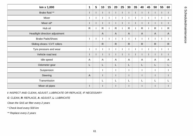
Scheduledservicingtable (06_01)
Adequate maintenance is fundamental to ensuring long-lasting, optimum operationand performance of your vehicle.
To this end, a series of checks and maintenance operations (at the owner's expense)have been suggested, which are included in the summary table on the following page.Any minor faults should be reported without delay to an Authorised Service Centreor Dealer without waiting until the next scheduled service to solve it.
It is indispensable to have your vehicle serviced to the prescribed intervals of time,even if you have not reached the predicted mileage. Punctual vehicle servicing isnecessary for the correct use of the guarantee. For any further information concerningWarranty procedures and 'Scheduled Maintenance', please refer to the 'WarrantyBooklet'.
MAINTENANCE TABLEkm x 1,000 1 5 10 15 20 25 30 35 40 45 50 55 60
Safety fasteners I I I I I I I
Spark plug I R I R I R I R I R I R
Drive belt I R I R I R I R
Mixer belt R R R
Throttle control - mixer A A A A A A A A A A A A A
Air filter C C C C C C C C C C C C
SAS filter I C I C I C I C
Electrical system and battery I I I I I I I I I I I I I
Cylinder ventilation system I I
Brake levers L L L L L L L L L L L L L
60
6 Sc
hedu
ledm
aint
enan
ce
km x 1,000 1 5 10 15 20 25 30 35 40 45 50 55 60
Brake fluid ** I I I I I I I I I I I I I
Mixer I I I I I I I I I I I I I
Mixer oil* I I I I I I I I I I I I I
Hub oil R I R I R I R I R I R I R
Headlight direction adjustment A A A A A A
Brake Pads/Shoes I I I I I I I I I I I I I
Sliding shoes / CVT rollers R R R R R R
Tyre pressure and wear I I I I I I I I I I I I I
Vehicle road test I I I I I I I I I I I I I
Idle speed A A A A A A A
Odometer gear L L L L L L L
Suspension I I I I I I
Steering A I I I I I I
Transmission L L L L L L
Mixer oil pipes I I I I I I I
I: INSPECT AND CLEAN, ADJUST, LUBRICATE OR REPLACE, IF NECESSARY
C: CLEAN, R: REPLACE, A: ADJUST, L: LUBRICATE
Clean the SAS air filter every 2 years
* Check level every 500 km
** Replace every 2 years
61
6 Scheduledmaintenance

TABLE OF RECOMMENDED PRODUCTSProduct Description Specifications
AGIP GEAR SAE 80W-90 Lubricant for gearboxes and transmissions. API GL-4
eni i-Ride PG 5W-40 Synthetic based lubricant for high-performancefour-stroke engines.
JASO MA, MA2 - API SL - ACEA A3
AGIP FILTER OIL Special product for the treatment of foamfilters.
-
eni i-Ride PG 2t Synthetic based lubricant for low smoke 2-stroke engines and additives.
API TC - JASO FC - ISO-L-EGD
AGIP GP 330 Water repellent stringy calcium spray grease. R.I.D./A.D.R. 2 10°b) 2 R.I.Na. 2.42 - I.A.T.A.2 - I.M.D.G. class 2 UN 1950 Page 9022 EM25-89
62
6 Sc
hedu
ledm
aint
enan
ce

TABLE OF CONTENTS
BBattery: 34
CChecks: 18Clock: 9
FFuses: 37
IIdentification: 14
KKeys: 13
MMaintenance: 27
PPuncture: 45
RRefuelling: 18
TToolkit: 55Tyres: 29
VVehicle: 7
63

The descriptions and images in this publication are given for illustrative purposes only and are not binding. While the basic characteristics as described and illustrated in this booklet remain unchanged,Piaggio & C. S.p.A. reserves the right, at any time and without being required to update this publication beforehand, to make any changes to components, parts or accessories, which it considers
necessary to improve the product or which are required for manufacturing or construction reasons.
Not all versions/models shown in this publication are available in all countries. The availability of each model should be checked at the official PIAGGIO sales network.
© Copyright 2012 - Piaggio & C. S.p.A. All rights reserved. Reproduction of this publication in whole or in part is prohibited.
Piaggio & C. S.p.A. Viale Rinaldo Piaggio, 25 - 56025 PONTEDERA (PI), Italy
www.piaggio.com