Embed Size (px)
Citation preview
PIAGGIO WOULD LIKE TO THANK YOU
for choosing one of its products. We have prepared this booklet to help you to get the very best from your scooter. Please read it carefully before ridingthe scooter for the first time. It contains information, tips and precautions for using your scooter. It also describes features, details and devices to assureyou that you have made the right choice. We believe that if you follow our suggestions, you will soon get to know your new vehicle and it will serve youwell for a long time to come. This booklet forms an integral part of the scooter; should the scooter be sold, it must be transferred to the new owner.
X8 400 i.e.
The instructions given in this manual are intended to provide a clear, simple guide to using your scooter; this booklet also details routine maintenanceprocedures and regular checks that should be carried out on the vehicle at an authorised Dealer or Service Centre. The booklet also containsinstructions for simple repairs. Any operations not specifically described in this manual require the use of special tools and/or particular technicalknowledge: to carry out these operations refer to any authorised Dealer of Service Centres.
2
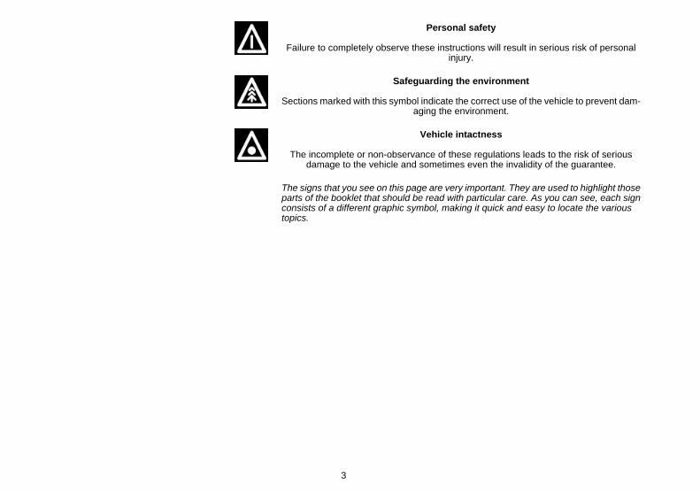
Personal safety
Failure to completely observe these instructions will result in serious risk of personalinjury.
Safeguarding the environment
Sections marked with this symbol indicate the correct use of the vehicle to prevent dam-aging the environment.
Vehicle intactness
The incomplete or non-observance of these regulations leads to the risk of seriousdamage to the vehicle and sometimes even the invalidity of the guarantee.
The signs that you see on this page are very important. They are used to highlight thoseparts of the booklet that should be read with particular care. As you can see, each signconsists of a different graphic symbol, making it quick and easy to locate the varioustopics.
3

4
INDEX
VEHICLE...................................................................................... 7Dashboard................................................................................ 8Analogue instrument panel....................................................... 9Clock......................................................................................... 10
Setting the hour/minutes function.......................................... 10Key switch................................................................................. 10
Locking the steering wheel.................................................... 11Releasing the steering wheel................................................ 11
Switch direction indicators........................................................ 11Horn button............................................................................... 12Light switch............................................................................... 12Start-up button.......................................................................... 13Engine stop button.................................................................... 13The immobilizer system............................................................ 13
Keys...................................................................................... 14Immobilizerdevice enabled indicator led............................... 15Operation............................................................................... 15Programming the immobilizer system................................... 16
Saddle opening remote control................................................. 18Remote control programming................................................ 18
Power supply socket................................................................. 20The saddle................................................................................ 20
Opening the saddle to access the helmet compartment byremote control....................................................................... 21Opening the saddle............................................................... 22Opening the saddle to access the helmet compartment in anemergency............................................................................. 22
Identification.............................................................................. 23Rear top box opening button..................................................... 24
USE.............................................................................................. 27Checks...................................................................................... 28Refuelling.................................................................................. 28Tyre pressure............................................................................ 30
Shock absorbers adjustment.................................................... 31Running in................................................................................. 32Starting up the engine............................................................... 33
Precautions........................................................................... 35Difficult start up......................................................................... 35Stopping the engine.................................................................. 36Stand......................................................................................... 37Automatic transmission............................................................. 38Safe driving............................................................................... 39
MAINTENANCE........................................................................... 43Engine oil level.......................................................................... 44
Engine oil level check............................................................ 44Engine oil top-up................................................................... 45Warning light (insufficient oil pressure)................................. 45Engine oil change.................................................................. 46
Hub oil level.............................................................................. 47Tyres......................................................................................... 49Spark plug dismantlement........................................................ 51Removing the air filter............................................................... 52Air filter cleaning....................................................................... 52Cooling fluid level...................................................................... 53Checking the brake oil level...................................................... 55
Braking system fluid top up................................................... 56Battery....................................................................................... 57
Use of a new battery............................................................. 57Checking the electrolyte level................................................ 58
Long periods of inactivity.......................................................... 59Fuses........................................................................................ 59Front light group........................................................................ 66
Headlight adjustment............................................................. 67Front direction indicators........................................................... 67Rear optical unit........................................................................ 68Rear turn indicators................................................................... 69
5
Number plate light..................................................................... 69Helmet compartment lighting bulb............................................ 70Rear-view mirrors...................................................................... 71Front and rear disc brake.......................................................... 71Puncture.................................................................................... 72Periods of inactivity................................................................... 73Cleaning the vehicle.................................................................. 74
TECHNICAL DATA...................................................................... 79Kit equipment............................................................................ 83
SPARE PARTS AND ACCESSORIES........................................ 85Warnings................................................................................... 86
PROGRAMMED MAINTENANCE............................................... 89Scheduled maintenance table................................................... 90
6
X8 400 i.e.
Chap. 01Vehicle
7
01_01
01_02
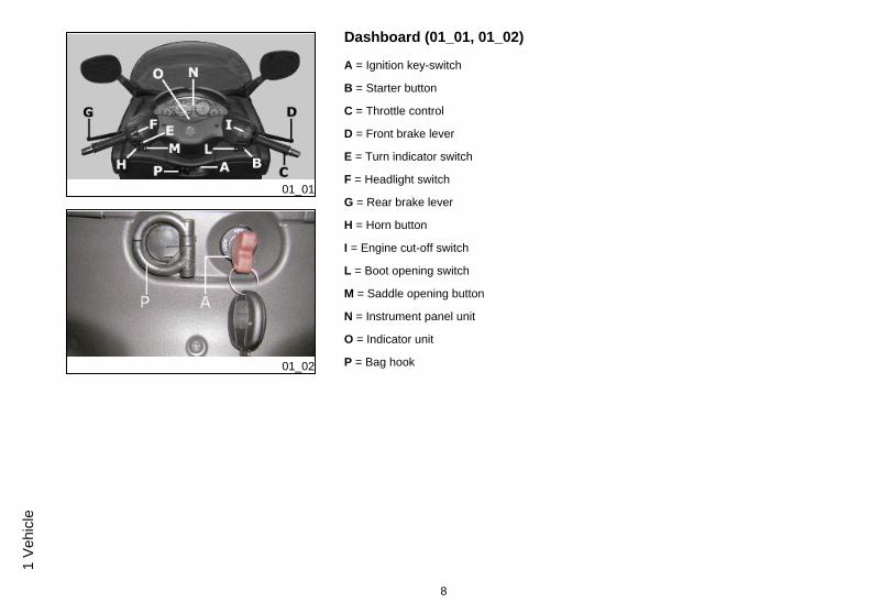
Dashboard (01_01, 01_02)
A = Ignition key-switch
B = Starter button
C = Throttle control
D = Front brake lever
E = Turn indicator switch
F = Headlight switch
G = Rear brake lever
H = Horn button
I = Engine cut-off switch
L = Boot opening switch
M = Saddle opening button
N = Instrument panel unit
O = Indicator unit
P = Bag hook
8
1 Ve
hicl
e
01_03
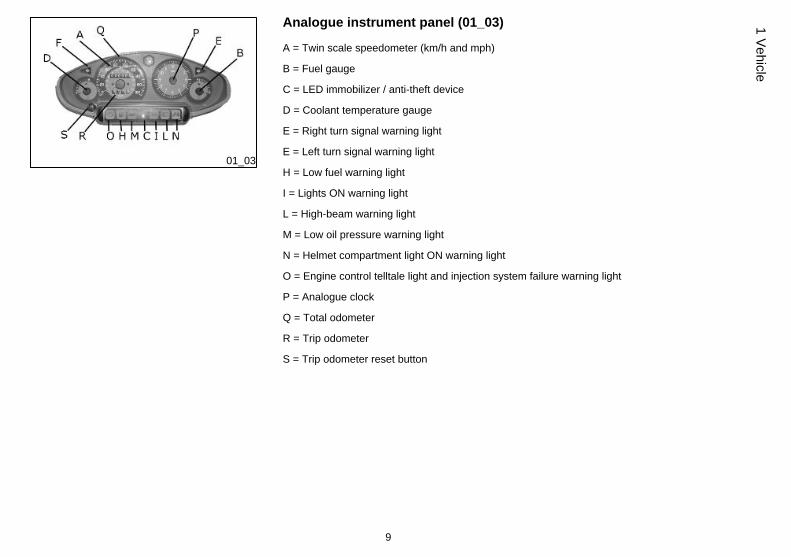
Analogue instrument panel (01_03)
A = Twin scale speedometer (km/h and mph)
B = Fuel gauge
C = LED immobilizer / anti-theft device
D = Coolant temperature gauge
E = Right turn signal warning light
E = Left turn signal warning light
H = Low fuel warning light
I = Lights ON warning light
L = High-beam warning light
M = Low oil pressure warning light
N = Helmet compartment light ON warning light
O = Engine control telltale light and injection system failure warning light
P = Analogue clock
Q = Total odometer
R = Trip odometer
S = Trip odometer reset button
9
1 Vehicle
01_04
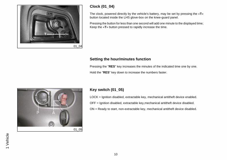
Clock (01_04)
The clock, powered directly by the vehicle's battery, may be set by pressing the «T»button located inside the LHS glove-box on the knee-guard panel.
Pressing the button for less than one second will add one minute to the displayed time;Keep the «T» button pressed to rapidly increase the time.
Setting the hour/minutes function
Pressing the "RES" key increases the minutes of the indicated time one by one.
Hold the "RES" key down to increase the numbers faster.
01_05
Key switch (01_05)
LOCK = Ignition disabled, extractable key, mechanical antitheft device enabled.
OFF = Ignition disabled, extractable key,mechanical antitheft device disabled.
ON = Ready to start, non-extractable key, mechanical antitheft device disabled.
10
1 Ve
hicl
e
Locking the steering wheel
Turn the handlebar to the left as far as it will go, turn the key to position "LOCK" andremove the key.
Releasing the steering wheel
Reinsert the key and turn it to «OFF».
CAUTION
DO NOT TURN THE KEY TO «LOCK» OR «OFF» WHILE RIDING.
01_06
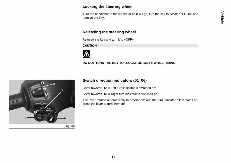
Switch direction indicators (01_06)
Lever towards "S" = Left turn indicator is switched on;
Lever towards "D" = Right turn indicator is switched on;
The lever returns automatically to position "0" and the turn indicator "B" remains on;press the lever to turn them off.
11
1 Vehicle
01_07
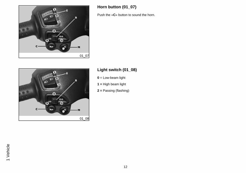
Horn button (01_07)
Push the «C» button to sound the horn.
01_08
Light switch (01_08)
0 = Low-beam light
1 = High beam light
2 = Passing (flashing)
12
1 Ve
hicl
e
01_09
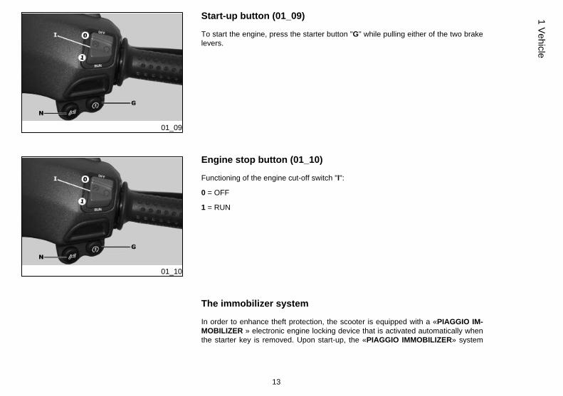
Start-up button (01_09)
To start the engine, press the starter button "G" while pulling either of the two brakelevers.
01_10
Engine stop button (01_10)
Functioning of the engine cut-off switch "I":
0 = OFF
1 = RUN
The immobilizer system
In order to enhance theft protection, the scooter is equipped with a «PIAGGIO IM-MOBILIZER » electronic engine locking device that is activated automatically whenthe starter key is removed. Upon start-up, the «PIAGGIO IMMOBILIZER» system
13
1 Vehicle
checks the starter key, and only if this key is recognised will the immobilizer systemallow the scooter to be started.
01_11
01_12
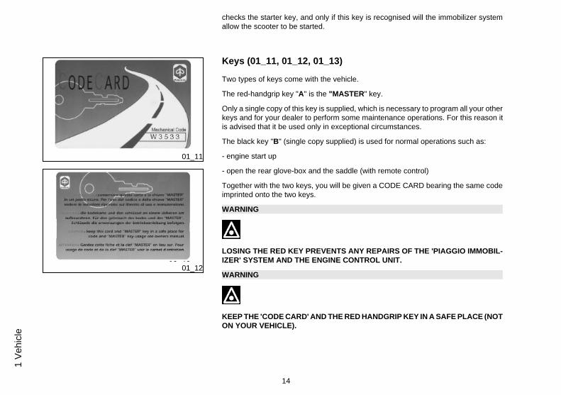
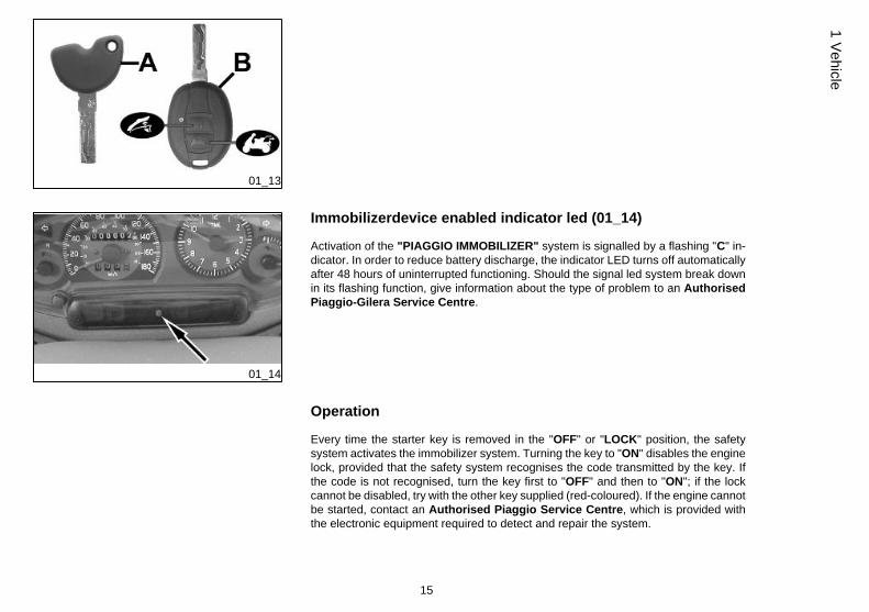
Keys (01_11, 01_12, 01_13)
Two types of keys come with the vehicle.
The red-handgrip key "A" is the "MASTER" key.
Only a single copy of this key is supplied, which is necessary to program all your otherkeys and for your dealer to perform some maintenance operations. For this reason itis advised that it be used only in exceptional circumstances.
The black key "B" (single copy supplied) is used for normal operations such as:
- engine start up
- open the rear glove-box and the saddle (with remote control)
Together with the two keys, you will be given a CODE CARD bearing the same codeimprinted onto the two keys.
WARNING
LOSING THE RED KEY PREVENTS ANY REPAIRS OF THE 'PIAGGIO IMMOBIL-IZER' SYSTEM AND THE ENGINE CONTROL UNIT.
WARNING
KEEP THE 'CODE CARD' AND THE RED HANDGRIP KEY IN A SAFE PLACE (NOTON YOUR VEHICLE).
14
1 Ve
hicl
e
01_13
01_14
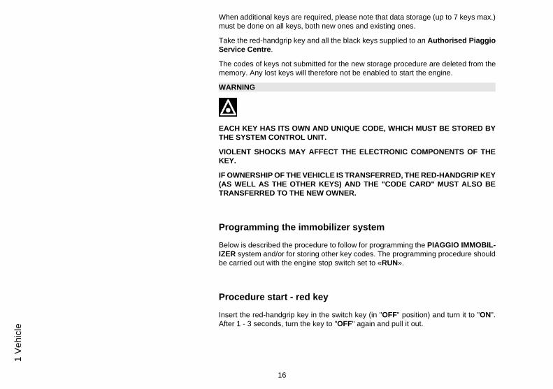
Immobilizerdevice enabled indicator led (01_14)
Activation of the "PIAGGIO IMMOBILIZER" system is signalled by a flashing "C" in-dicator. In order to reduce battery discharge, the indicator LED turns off automaticallyafter 48 hours of uninterrupted functioning. Should the signal led system break downin its flashing function, give information about the type of problem to an AuthorisedPiaggio-Gilera Service Centre.
Operation
Every time the starter key is removed in the "OFF" or "LOCK" position, the safetysystem activates the immobilizer system. Turning the key to "ON" disables the enginelock, provided that the safety system recognises the code transmitted by the key. Ifthe code is not recognised, turn the key first to "OFF" and then to "ON"; if the lockcannot be disabled, try with the other key supplied (red-coloured). If the engine cannotbe started, contact an Authorised Piaggio Service Centre, which is provided withthe electronic equipment required to detect and repair the system.
15
1 Vehicle
When additional keys are required, please note that data storage (up to 7 keys max.)must be done on all keys, both new ones and existing ones.
Take the red-handgrip key and all the black keys supplied to an Authorised PiaggioService Centre.
The codes of keys not submitted for the new storage procedure are deleted from thememory. Any lost keys will therefore not be enabled to start the engine.
WARNING
EACH KEY HAS ITS OWN AND UNIQUE CODE, WHICH MUST BE STORED BYTHE SYSTEM CONTROL UNIT.
VIOLENT SHOCKS MAY AFFECT THE ELECTRONIC COMPONENTS OF THEKEY.
IF OWNERSHIP OF THE VEHICLE IS TRANSFERRED, THE RED-HANDGRIP KEY(AS WELL AS THE OTHER KEYS) AND THE "CODE CARD" MUST ALSO BETRANSFERRED TO THE NEW OWNER.
Programming the immobilizer system
Below is described the procedure to follow for programming the PIAGGIO IMMOBIL-IZER system and/or for storing other key codes. The programming procedure shouldbe carried out with the engine stop switch set to «RUN».
Procedure start - red key
Insert the red-handgrip key in the switch key (in "OFF" position) and turn it to "ON".After 1 - 3 seconds, turn the key to "OFF" again and pull it out.
16
1 Ve
hicl
e
Intermediate step - black key
After pulling out the red key, insert the black key within 10 seconds and promptly turnit to «ON». After 1-3 seconds, turn the key to "OFF" again and pull it out. In this way,a maximum of 7 black keys can be programmed by repeating the above procedurekeeping the indicated times.
Final step - red key
After pulling out the last black key, insert the red key again and turn it to "ON" (thisoperation should be performed within 10 seconds of pulling out the previous key).Leave it in this position for 1 to 3 seconds and return it to the «OFF» position.
Proper programming check
Insert the red key disabling the transponder (i.e., tilt the key cap by 90°) and turn thekey to "ON". Perform the engine start-up operation. Ensure that the engine does notstart. Insert the black key and repeat the start-up operation. Check that engine starts.
WARNING
SHOULD THE ENGINE START WITH THE RED KEY (WITH TRANSPONDER OFF),OR IN THE EVENT OF WRONG OPERATION DURING PROGRAMMING, REPEATTHE PROCEDURE FROM THE BEGINNING.
17
1 Vehicle
01_15
01_16
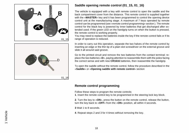
Saddle opening remote control (01_15, 01_16)
The vehicle is equipped with a key with remote control to open the saddle and theback compartment cover from the distance. This remote control is supplied togetherwith the «MASTER» key and it has been programmed to control the opening devicecontrol unit at the manufacturing stage. A maximum of 7 keys operated by remotecontrol can be programmed (see «remote control programming» section ). The remotecontrol for the black key is powered by inner batteries that get discharged after ex-tended used; If the green LED on the handgrip turns on when the button is pressed,the remote control is working properly.You may need to replace the batteries inside the key if the remote control fails or if itsrange of operation is reduced.
In order to carry out this operation, separate the two halves of the remote control byinserting an edge or the thin tip of a plain slot screwdriver on the external groove andslide it all around said groove.
Go to the printed circuit and remove the two batteries from the contact terminal; re-place the two batteries «D», paying attention to reassemble them with the poles facingthe correct sense and with new CR1616 batteries, then reassemble the handgrip.
To open the saddle without the remote control, follow the procedure described in the«Saddle» or «Opening saddle with remote control» section
Remote control programming
Follow these steps to program the remote controls:1. Insert the remote control key to be programmed in the steering lock key block.
2. Turn the key to «ON», press the button on the remote control, release the button,turn the key back to «OFF» from the «ON» position, all within 4 seconds.
3 Wait 1 to 8 seconds.
4. Repeat steps 2 and 3 for 4 times without removing the key.
18
1 Ve
hicl
e
The control unit confirms the programming has been successfully executed by open-ing the saddle.
WARNING
TO STORE THE OTHER REMOTE CONTROLS TO MEMORY, (MAXIMUM 8), YOUNEED TO REPEAT THE WHOLE PROCEDURE AGAIN. FAILURE TO CARRY OUTTHESE OPERATIONS WITHIN THE INDICATED TIMES WILL RESULT IN THEAUTOMATIC CANCELLATION OF THE PROCESS FOR PROGRAMMING THEREMOTE-CONTROLLED KEYS.
WARNING
AVOID PRESSING THE REMOTE CONTROL BUTTON MORE THAN ONCE WHENFAR AWAY FROM THE SCOOTER. THE SYNCHRONISM BETWEEN THE RE-MOTE CONTROL AND THE RECEIVER CAN BE IMPAIRED. SHOULD THIS BETHE CASE, REPEAT THE PROGRAMMING PROCEDURE. DO NOT KEEP THEREMOTE CONTROL IN PLACES WITH TEMPERATURES EXCEEDING 60° C THEBATTERY WILL RUN DOWN TOO QUICKLY.
WARNING
TO AVOID BATTERY DISCHARGE, THE SADDLE OPENING REMOTE CONTROLRADIO RECEIVER DEACTIVATES 7 DAYS AFTER THE LAST TIME THE VEHICLEWAS SHUT OFF.
JUST TURN THE KEY TO «ON» TO REACTIVATE THE RECEIVER.
19
1 Vehicle
01_17
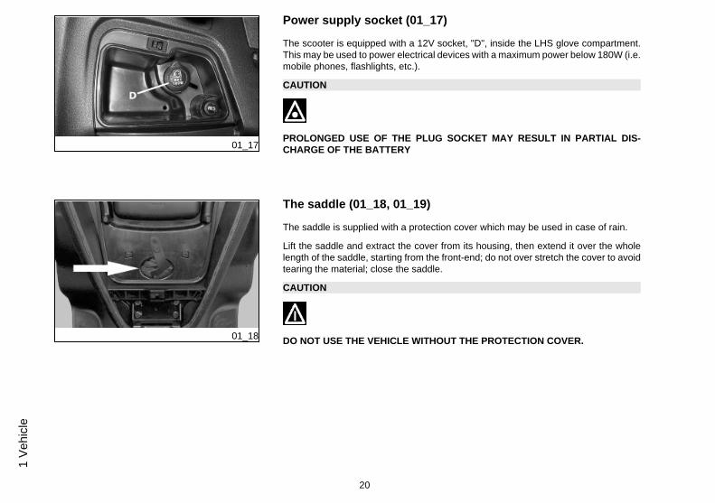
Power supply socket (01_17)
The scooter is equipped with a 12V socket, "D", inside the LHS glove compartment.This may be used to power electrical devices with a maximum power below 180W (i.e.mobile phones, flashlights, etc.).
CAUTION
PROLONGED USE OF THE PLUG SOCKET MAY RESULT IN PARTIAL DIS-CHARGE OF THE BATTERY
01_18
The saddle (01_18, 01_19)
The saddle is supplied with a protection cover which may be used in case of rain.
Lift the saddle and extract the cover from its housing, then extend it over the wholelength of the saddle, starting from the front-end; do not over stretch the cover to avoidtearing the material; close the saddle.
CAUTION
DO NOT USE THE VEHICLE WITHOUT THE PROTECTION COVER.
20
1 Ve
hicl
e
01_19
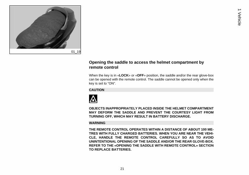
Opening the saddle to access the helmet compartment byremote control
When the key is in «LOCK» or «OFF» position, the saddle and/or the rear glove-boxcan be opened with the remote control. The saddle cannot be opened only when thekey is set to "ON".
CAUTION
OBJECTS INAPPROPRIATELY PLACED INSIDE THE HELMET COMPARTMENTMAY DEFORM THE SADDLE AND PREVENT THE COURTESY LIGHT FROMTURNING OFF, WHICH MAY RESULT IN BATTERY DISCHARGE.
WARNING
THE REMOTE CONTROL OPERATES WITHIN A DISTANCE OF ABOUT 100 ME-TRES WITH FULLY CHARGED BATTERIES. WHEN YOU ARE NEAR THE VEHI-CLE, HANDLE THE REMOTE CONTROL CAREFULLY SO AS TO AVOIDUNINTENTIONAL OPENING OF THE SADDLE AND/OR THE REAR GLOVE-BOX.REFER TO THE «OPENING THE SADDLE WITH REMOTE CONTROL» SECTIONTO REPLACE BATTERIES.
21
1 Vehicle
01_20
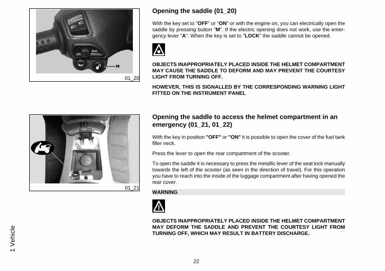
Opening the saddle (01_20)
With the key set to "OFF" or "ON" or with the engine on, you can electrically open thesaddle by pressing button "M". If the electric opening does not work, use the emer-gency lever "A". When the key is set to "LOCK" the saddle cannot be opened.
OBJECTS INAPPROPRIATELY PLACED INSIDE THE HELMET COMPARTMENTMAY CAUSE THE SADDLE TO DEFORM AND MAY PREVENT THE COURTESYLIGHT FROM TURNING OFF.
HOWEVER, THIS IS SIGNALLED BY THE CORRESPONDING WARNING LIGHTFITTED ON THE INSTRUMENT PANEL
01_21
Opening the saddle to access the helmet compartment in anemergency (01_21, 01_22)
With the key in position "OFF" or "ON" it is possible to open the cover of the fuel tankfiller neck.
Press the lever to open the rear compartment of the scooter.
To open the saddle it is necessary to press the metallic lever of the seat lock manuallytowards the left of the scooter (as seen in the direction of travel). For this operationyou have to reach into the inside of the luggage compartment after having opened therear cover.
WARNING
OBJECTS INAPPROPRIATELY PLACED INSIDE THE HELMET COMPARTMENTMAY DEFORM THE SADDLE AND PREVENT THE COURTESY LIGHT FROMTURNING OFF, WHICH MAY RESULT IN BATTERY DISCHARGE.
22
1 Ve
hicl
e
01_22
01_23
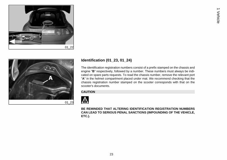
Identification (01_23, 01_24)
The identification registration numbers consist of a prefix stamped on the chassis andengine "B" respectively, followed by a number. These numbers must always be indi-cated on spare parts requests. To read the chassis number, remove the relevant port"A" in the helmet compartment placed under mat. We recommend checking that thechassis registration number stamped on the scooter corresponds with that on thescooter's documents.
CAUTION
BE REMINDED THAT ALTERING IDENTIFICATION REGISTRATION NUMBERSCAN LEAD TO SERIOUS PENAL SANCTIONS (IMPOUNDING OF THE VEHICLE,ETC.).
23
1 Vehicle
01_24
01_25
01_26
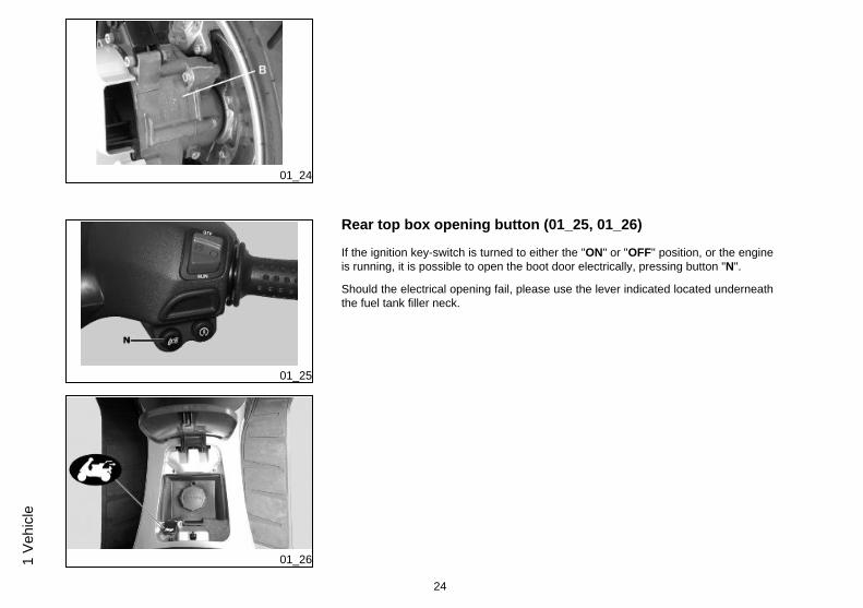
Rear top box opening button (01_25, 01_26)
If the ignition key-switch is turned to either the "ON" or "OFF" position, or the engineis running, it is possible to open the boot door electrically, pressing button "N".
Should the electrical opening fail, please use the lever indicated located underneaththe fuel tank filler neck.
24
1 Ve
hicl
e

25
1 Vehicle

26
1 Ve
hicl
e
X8 400 i.e.
Chap. 02Use
27
Checks
Before using the vehicle, check:
1. There is enough fuel in the fuel tank.
2. The correct fluid level for front and rear brakes.
3. That tyres are properly inflated.
4. The correct functioning of tail lights, headlamp, turn indicators, stop light and licenseplate light.
5. The correct functioning of front and rear brakes.
6. The oil level in the gearcase.
7. The engine oil level.
8. The coolant level.
02_01
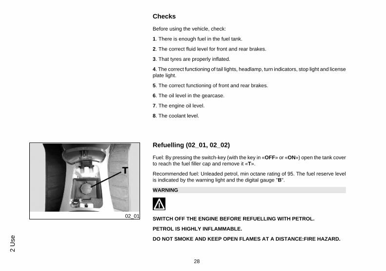
Refuelling (02_01, 02_02)
Fuel: By pressing the switch-key (with the key in «OFF» or «ON») open the tank coverto reach the fuel filler cap and remove it «T».
Recommended fuel: Unleaded petrol, min octane rating of 95. The fuel reserve levelis indicated by the warning light and the digital gauge "B".
WARNING
SWITCH OFF THE ENGINE BEFORE REFUELLING WITH PETROL.
PETROL IS HIGHLY INFLAMMABLE.
DO NOT SMOKE AND KEEP OPEN FLAMES AT A DISTANCE:FIRE HAZARD.
28
2 U
se
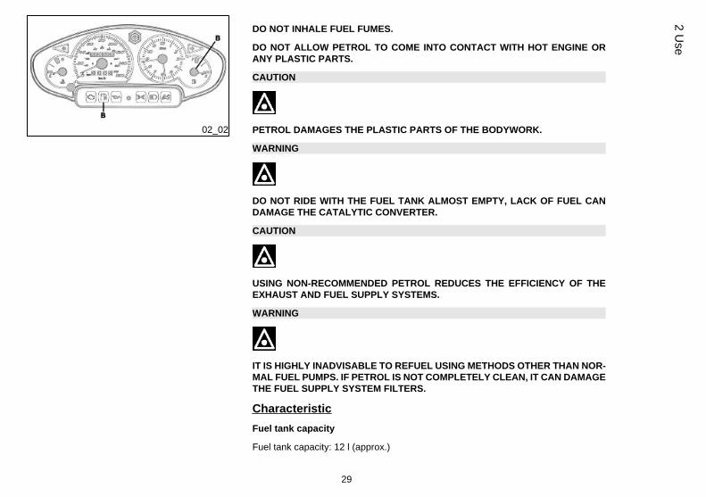
02_02
DO NOT INHALE FUEL FUMES.
DO NOT ALLOW PETROL TO COME INTO CONTACT WITH HOT ENGINE ORANY PLASTIC PARTS.
CAUTION
PETROL DAMAGES THE PLASTIC PARTS OF THE BODYWORK.
WARNING
DO NOT RIDE WITH THE FUEL TANK ALMOST EMPTY, LACK OF FUEL CANDAMAGE THE CATALYTIC CONVERTER.
CAUTION
USING NON-RECOMMENDED PETROL REDUCES THE EFFICIENCY OF THEEXHAUST AND FUEL SUPPLY SYSTEMS.
WARNING
IT IS HIGHLY INADVISABLE TO REFUEL USING METHODS OTHER THAN NOR-MAL FUEL PUMPS. IF PETROL IS NOT COMPLETELY CLEAN, IT CAN DAMAGETHE FUEL SUPPLY SYSTEM FILTERS.
CharacteristicFuel tank capacity
Fuel tank capacity: 12 l (approx.)
29
2 Use
Fuel reserve
approx. 2.5 litres (indicative value)
02_03
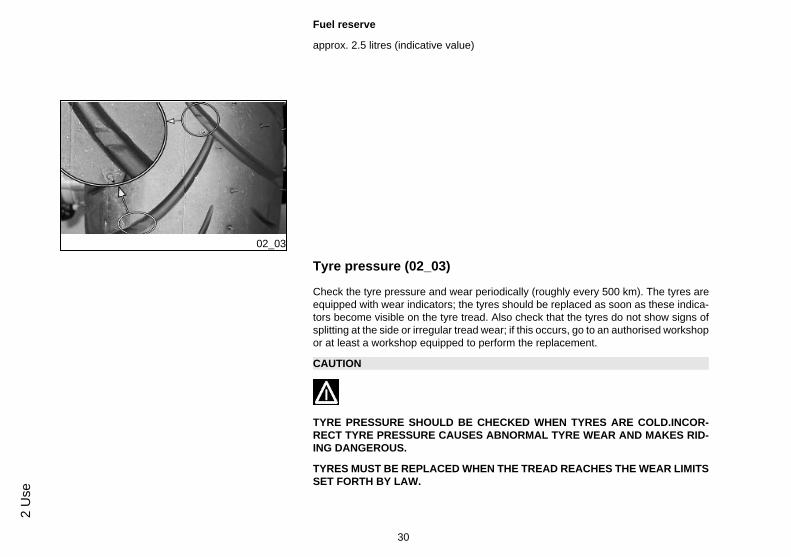
Tyre pressure (02_03)
Check the tyre pressure and wear periodically (roughly every 500 km). The tyres areequipped with wear indicators; the tyres should be replaced as soon as these indica-tors become visible on the tyre tread. Also check that the tyres do not show signs ofsplitting at the side or irregular tread wear; if this occurs, go to an authorised workshopor at least a workshop equipped to perform the replacement.
CAUTION
TYRE PRESSURE SHOULD BE CHECKED WHEN TYRES ARE COLD.INCOR-RECT TYRE PRESSURE CAUSES ABNORMAL TYRE WEAR AND MAKES RID-ING DANGEROUS.
TYRES MUST BE REPLACED WHEN THE TREAD REACHES THE WEAR LIMITSSET FORTH BY LAW.
30
2 U
se
CharacteristicFront tyre pressure
2.2 bar
Rear tyre pressure
2.4 bar
Rear wheel pressure (rider and passenger):
2.5 bar
02_04
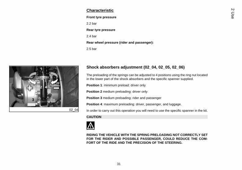
Shock absorbers adjustment (02_04, 02_05, 02_06)
The preloading of the springs can be adjusted to 4 positions using the ring nut locatedin the lower part of the shock absorbers and the specific spanner supplied.
Position 1: minimum preload: driver only
Position 2 medium preloading: driver only
Position 3 medium preloading: rider and passenger
Position 4: maximum preloading: driver, passenger, and luggage.
In order to carry out this operation you will need to use the specific spanner in the kit.
CAUTION
RIDING THE VEHICLE WITH THE SPRING PRELOADING NOT CORRECTLY SETFOR THE RIDER AND POSSIBLE PASSENGER, COULD REDUCE THE COM-FORT OF THE RIDE AND THE PRECISION OF THE STEERING.
31
2 Use
02_05
02_06
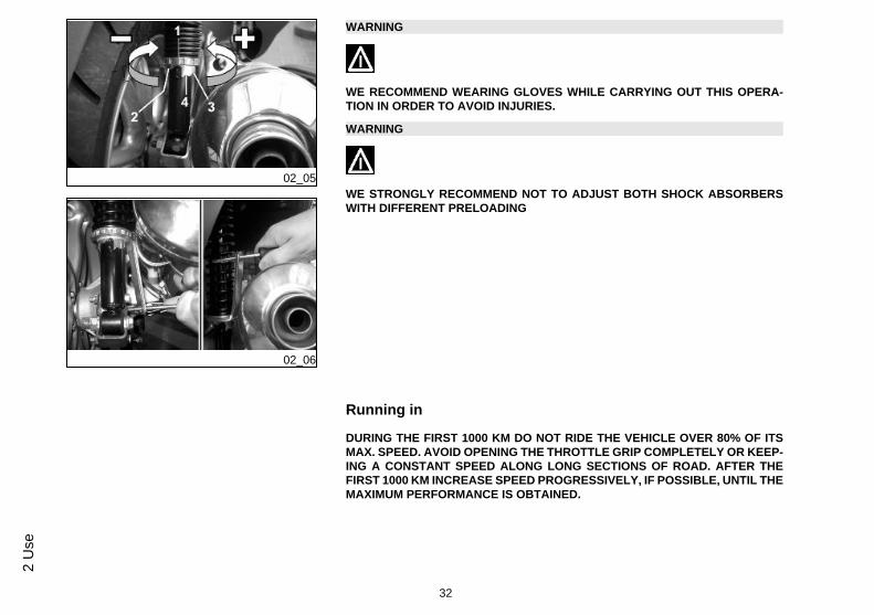
WARNING
WE RECOMMEND WEARING GLOVES WHILE CARRYING OUT THIS OPERA-TION IN ORDER TO AVOID INJURIES.
WARNING
WE STRONGLY RECOMMEND NOT TO ADJUST BOTH SHOCK ABSORBERSWITH DIFFERENT PRELOADING
Running in
DURING THE FIRST 1000 KM DO NOT RIDE THE VEHICLE OVER 80% OF ITSMAX. SPEED. AVOID OPENING THE THROTTLE GRIP COMPLETELY OR KEEP-ING A CONSTANT SPEED ALONG LONG SECTIONS OF ROAD. AFTER THEFIRST 1000 KM INCREASE SPEED PROGRESSIVELY, IF POSSIBLE, UNTIL THEMAXIMUM PERFORMANCE IS OBTAINED.
32
2 U
se
CAUTION
IN ORDER TO AVOID DAMAGING THE VEHICLE, PLEASE COMPLY WITH THERULES LISTED ABOVE.
02_07
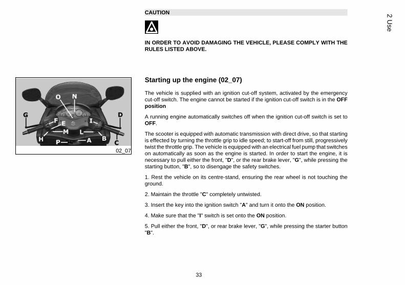
Starting up the engine (02_07)
The vehicle is supplied with an ignition cut-off system, activated by the emergencycut-off switch. The engine cannot be started if the ignition cut-off switch is in the OFFposition
A running engine automatically switches off when the ignition cut-off switch is set toOFF.
The scooter is equipped with automatic transmission with direct drive, so that startingis effected by turning the throttle grip to idle speed; to start-off from still, progressivelytwist the throttle grip. The vehicle is equipped with an electrical fuel pump that switcheson automatically as soon as the engine is started. In order to start the engine, it isnecessary to pull either the front, "D", or the rear brake lever, "G", while pressing thestarting button, "B", so to disengage the safety switches.
1. Rest the vehicle on its centre-stand, ensuring the rear wheel is not touching theground.
2. Maintain the throttle "C" completely untwisted.
3. Insert the key into the ignition switch "A" and turn it onto the ON position.
4. Make sure that the "I" switch is set onto the ON position.
5. Pull either the front, "D", or rear brake lever, "G", while pressing the starter button"B".
33
2 Use
WARNING
THE AUTOMATIC TRANSMISSION MAKES THE REAR WHEEL TURN EVENWHEN THE THROTTLE IS SLIGHTLY TWISTED. RELEASE THE BRAKE CARE-FULLY AFTER STARTING, AND THEN ACCELERATE GRADUALLY.
CAUTION
DO NOT START-UP THE ENGINE IN CLOSED AREAS BECAUSE EXHAUSTGASES ARE TOXIC.
CAUTION
DUE TO THE HIGH TEMPERATURES THE CATALYTIC CONVERTER CANREACH, ALWAYS TAKE CARE, WHEN PARKING THE SCOOTER, THAT THEEXHAUST DOES NOT COME INTO CONTACT WITH FLAMMABLE MATERIALS,TO AVOID SERIOUS BURNS.
CAUTION
DO NOT SWITCH OFF THE ENGINE WHILE THE VEHICLE IS MOVING. UN-BURNED FUEL COULD ENTER THE CATALYTIC CONVERTER AND BURN,CAUSING IT TO OVERHEAT AND POSSIBLY DESTROYING IT.
34
2 U
se
Precautions
CAUTION
NEVER STRESS THE ENGINE AT LOW TEMPERATURES IN ORDER TO AVOIDPOSSIBLE DAMAGE. BE CAREFUL NEVER TO EXCEED THE MAXIMUM SPEEDWHILE RUNNING DOWNHILL, IN ORDER TO AVOID DAMAGING THE ENGINE.IN ANY CASE, IN ORDER TO PRESERVE THE ENGINE FROM PROLONGED EX-CESSIVE REVOLUTIONS, THE REVOLUTION LIMITER WILL BE ACTIVATED IFTHE ENGINE SPEED EXCEEDS THE ESTABLISHED THRESHOLD.
WARNING
AFTER A LONG DISTANCE COVERED AT THE MAXIMUM SPEED, DO NOT STOPTHE ENGINE IMMEDIATELY, BUT LET IT RUN AT IDLE FOR A FEW SECONDS.
Difficult start up
In the rare event of a flooded engine, and to facilitate start-up, it is possible to attemptto operate start engine with the throttle partially or fully twisted. It is however neces-sary, once the engine is started, to visit an Authorised Piaggio Service Centre todetermine the cause and make certain that the scooter functions properly.In case of fuel exhaustion:After having refilled the scooter, start it, using the starterswitch «A» and keeping the gas hand grip at the minimum. If you cannot start thescooter using the above methods then turn to an Authorised Piaggio-Gilera ServiceCentre.
Faulty battery and start-up with auxiliary battery:If the battery is dead it is possibleto start the engine by means of a connection to another battery, with cables capableof accepting high current and with clamps at the ends. If the auxiliary battery is installed
35
2 Use
in another scooter, do not allow the two scooters to touch and position them both onthe centre stand (if the other scooter has one).
Proceed as follows:
a) Switch off all services and users, start up the vehicle with the auxiliary battery andmake the engine run slightly above idle to ensure deep battery charge; then turn offthe engine.
b) Set the vehicle key switch to "OFF".
c) Connect the positive terminal (+) of the discharged battery to the positive terminal(+) of the auxiliary battery, and the negative terminal (-) of the discharged battery tothe negative terminal (-) of the auxiliary battery.
d) Try to start the scooter by alternating 5 seconds of turning the starter motor with 5seconds of pause. If the motor does not start after 20" of using the start-up system,do not continue with the attempt, since the scooter might not start due to some otherproblem.
e) Once the engine has started, keep it running slightly above idle and disconnect thecable (one cable at a time from both battery terminals) following the reverse mountingprocedure: first the negative terminal (-) and then the positive one (+). As soon as youcan, control the electrolyte level (in the case of unsealed batteries) and top up withdistilled water, if necessary. If the fault that causes the battery to discharge is unknown,contact an authorised Piaggio Service Centre to check the vehicle's electrical sys-tem.
Stopping the engine
Fully untwist the throttle grip, then rotate the key in the switch «A » to «KEYOFF» (extractable key).
36
2 U
se
CAUTION
DUE TO THE HIGH TEMPERATURES THE CATALYTIC CONVERTER CANREACH, ALWAYS TAKE CARE, WHEN PARKING THE SCOOTER, THAT THEEXHAUST DOES NOT COME INTO CONTACT WITH FLAMMABLE MATERIALS,TO AVOID SERIOUS BURNS.
CAUTION
DO NOT SWITCH OFF THE ENGINE WHILE THE VEHICLE IS MOVING. UN-BURNED FUEL COULD ENTER THE CATALYTIC CONVERTER AND BURN,CAUSING IT TO OVERHEAT AND POSSIBLY DESTROYING IT.
WARNING
TO START AFTER A LONG STATIONARY PERIOD, OR IN SEVERE WEATHERCONDITIONS, FULLY TWIST THE THROTTLE 2÷3 TIMES BEFORE PRESSINGTHE STARTER BUTTON.
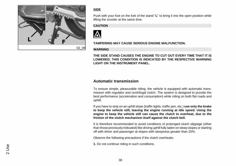
Stand (02_08)
CENTRE STAND
Push with your foot on the centre stand's fork «F» while lifting the vehicle backward,holding onto the handlebar.
37
2 Use
02_08
SIDE
Push with your foot on the fork of the stand "L" to bring it into the open position whilelifting the scooter at the same time.
CAUTION
TAMPERING MAY CAUSE SERIOUS ENGINE MALFUNCTION.
WARNING
THE SIDE STAND CAUSES THE ENGINE TO CUT OUT EVERY TIME THAT IT ISLOWERED; THIS CONDITION IS INDICATED BY THE RESPECTIVE WARNINGLIGHT ON THE INSTRUMENT PANEL.
Automatic transmission
To ensure simple, pleasurable riding, the vehicle is equipped with automatic trans-mission with regulator and centrifugal clutch. The system is designed to provide thebest performance (acceleration and consumption) while riding on both flat roads anduphill.
If you have to stop on an uphill slope (traffic lights, traffic jam, etc.) use only the braketo keep the vehicle still, leaving the engine running at idle speed. Using theengine to keep the vehicle still can cause the clutch to overheat, due to thefriction of the clutch mechanism itself against the clutch bell.
It is therefore recommended to avoid conditions of prolonged clutch slippage (otherthan those previously indicated) like driving uphill fully laden on steep slopes or startingoff with driver and passenger at slopes with steepness greater than 25%.
Observe the following precautions if the clutch overheats:
1. Do not continue riding in such conditions.
38
2 U
se
2. Let the clutch cool down with the engine at idle speed for a few minutes.
Safe driving
Some simple tips are provided below that will enable you to use your vehicle on a dailybasis in greater safety and peace of mind. Your skill and your mechanical knowledgeare the basis of safe riding. We recommend trying out the vehicle in traffic - free zones,in order to acquire a good knowledge of the vehicle it self.
1. Before riding off, remember to put on your helmet and fasten it correctly.
2.Reduce speed on rough roads and drive with care.
3. After riding on a long stretch of wet road without using the brakes, braking can bepoor at the beginning. Given these conditions, it is a good idea to operate the brakesfrom time to time.
4. Do not brake hard on wet, dirt or slippery road surfaces.
5. Avoid riding off by mounting the scooter when resting on the support. In any case,the rear wheel should not be turning when in comes into contact with the ground, inorder to avoid abrupt departures.
6. When riding along roads covered by sand, mud, snow mixed with salt, etc. werecommend cleaning the brake disc frequently with a non-corrosive detergent in orderto prevent corrosive particles from building up in the holes, which may cause earlybrake pad wear.
CAUTION
ALWAYS RIDE WITHIN YOUR LIMITS RIDING UNDER THE INFLUENCE OF AL-COHOL OR OTHER DRUGS AND CERTAIN MEDICATIONS IS EXTREMELY DAN-GEROUS.
39
2 Use
CAUTION
IN ORDER TO PREVENT ANY ACCIDENTS RIDE VERY CAREFULLY AFTERADDING ACCESSORIES AND WHILE CARRYING LUGGAGE. ADDING ACCES-SORIES AND LUGGAGE CAN REDUCE THE VEHICLE'S STABILITY, PERFORM-ANCE AND SAFETY DURING USE.
WARNING
NEVER RIDE THE SCOOTER EQUIPPED WITH ACCESSORIES (TOP BOX AND/OR WINDSHIELD) AT A SPEED HIGHER THAN 100 km/h.
THE SCOOTER CAN BE RIDDEN AT A HIGHER SPEED WITHOUT THE ACCES-SORIES MENTIONED BEFORE WITHIN THE LIMITS ESTABLISHED BY LAW.
IF THERE SHOULD BE NON-PIAGGIO ACCESSORIES INSTALLED, OR AN AB-NORMAL LOAD, OR IF THE SCOOTER IS NOT IN A GENERALLY GOOD CON-DITION, OR WHENEVER WEATHER CONDITIONS DEMAND IT, SPEED SHOULDBE REDUCED FURTHER.
CAUTION
DO NOT ADJUST THE MIRRORS WHILE RIDING. THIS COULD CAUSE YOU TOLOOSE CONTROL OF THE VEHICLE.
CAUTION
ANY CHANGES TO THE VEHICLE PERFORMANCE AS WELL AS ALTERATIONSTO ORIGINAL STRUCTURAL PARTS IS STRICTLY FORBIDDEN BY LAW, AND
40
2 U
se
RENDERS THE VEHICLE NO LONGER CONFORMING TO THE APPROVED TYPEAND DANGEROUS FOR RIDING.
41
2 Use

42
2 U
se
X8 400 i.e.
Chap. 03Maintenance
43
Engine oil level
In 4-stroke engines, engine oil is used to lubricate the distribution elements, the bush-es and the thermal group. An insufficient quantity of oil can cause serious damageto the engine.In all four-stroke engines, a loss of efficiency in oil performance andconsumption should be considered normal. Consumption can particularly reflect theconditions of use (i.e. when driving at "full acceleration" all the time, oil consumptionincreases). The replacement frequencies provided for by the maintenance programmeare defined, depending on the total contents of oil in the engine and average con-sumption measured following standardised methods.
In order to prevent any problems, we recommend checking oil level more fre-quently than indicated in the Scheduled Maintenance table or before setting offon long journeys. The scooter is, however, equipped with an oil pressure warn-ing light on the instrument panel.
03_01
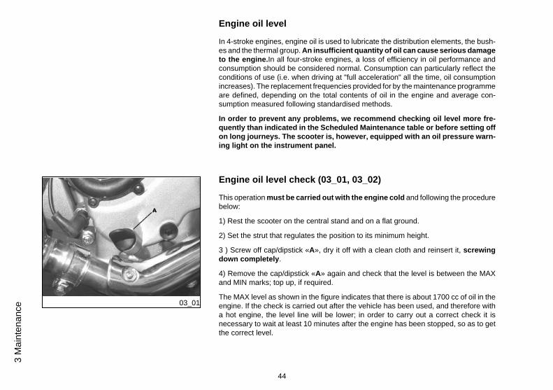
Engine oil level check (03_01, 03_02)
This operation must be carried out with the engine cold and following the procedurebelow:
1) Rest the scooter on the central stand and on a flat ground.
2) Set the strut that regulates the position to its minimum height.
3 ) Screw off cap/dipstick «A», dry it off with a clean cloth and reinsert it, screwingdown completely.
4) Remove the cap/dipstick «A» again and check that the level is between the MAXand MIN marks; top up, if required.
The MAX level as shown in the figure indicates that there is about 1700 cc of oil in theengine. If the check is carried out after the vehicle has been used, and therefore witha hot engine, the level line will be lower; in order to carry out a correct check it isnecessary to wait at least 10 minutes after the engine has been stopped, so as to getthe correct level.
44
3 M
aint
enan
ce
03_02
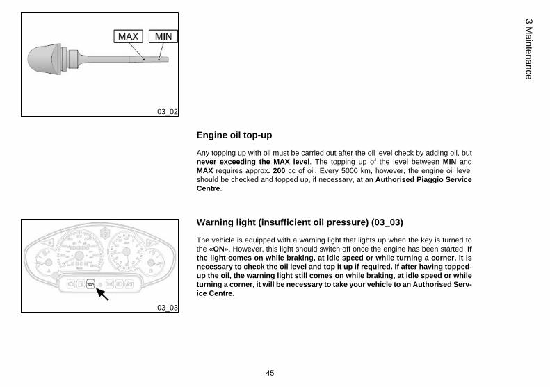
Engine oil top-up
Any topping up with oil must be carried out after the oil level check by adding oil, butnever exceeding the MAX level. The topping up of the level between MIN andMAX requires approx. 200 cc of oil. Every 5000 km, however, the engine oil levelshould be checked and topped up, if necessary, at an Authorised Piaggio ServiceCentre.
03_03
Warning light (insufficient oil pressure) (03_03)
The vehicle is equipped with a warning light that lights up when the key is turned tothe «ON». However, this light should switch off once the engine has been started. Ifthe light comes on while braking, at idle speed or while turning a corner, it isnecessary to check the oil level and top it up if required. If after having topped-up the oil, the warning light still comes on while braking, at idle speed or whileturning a corner, it will be necessary to take your vehicle to an Authorised Serv-ice Centre.
45
3 Maintenance
03_04
03_05
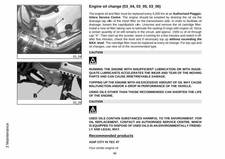
Engine oil change (03_04, 03_05, 03_06)
The engine oil and filter must be replaced every 6,000 km at an Authorised Piaggio-Gilera Service Centre. The engine should be emptied by draining the oil via thedrainage tap «B» of the mesh filter on the transmission side. In order to facilitate oildrainage, loosen the cap/dipstick «A». Unscrew and remove the oil cartridge filter.Install a new oil filter taking care to lubricate the sealing O-rings with engine oil. Sincea certain quantity of oil still remains in the circuit, add approx. 1500 cc of oil throughcap "A". Then start up the scooter, leave it running for a few minutes and switch it off:after five minutes, check the level and if necessary top up without exceeding theMAX. level. The cartridge filter must be replaced at every oil change. For top-ups andoil changes, use new oil of the recommended type.
CAUTION
RUNNING THE ENGINE WITH INSUFFICIENT LUBRICATION OR WITH INADE-QUATE LUBRICANTS ACCELERATES THE WEAR AND TEAR OF THE MOVINGPARTS AND CAN CAUSE IRRETRIEVABLE DAMAGE.
TOPPING UP THE ENGINE WITH AN EXCESSIVE AMOUNT OF OIL MAY CAUSEMALFUNCTION AND/OR A DROP IN PERFORMANCE OF THE VEHICLE.
USING OILS OTHER THAN THOSE RECOMMENDED CAN SHORTEN THE LIFEOF THE ENGINE.
CAUTION
USED OILS CONTAIN SUBSTANCES HARMFUL TO THE ENVIRONMENT. FOROIL REPLACEMENT, CONTACT AN AUTHORISED SERVICE CENTRE, WHICHIS EQUIPPED TO DISPOSE OF USED OILS IN AN ENVIRONMENTALLY FRIEND-LY AND LEGAL WAY.
Recommended productsAGIP CITY HI TEC 4T
Four-stroke engine oil
46
3 M
aint
enan
ce
03_06
Lubricating oil for flexible shafts (throttle control)
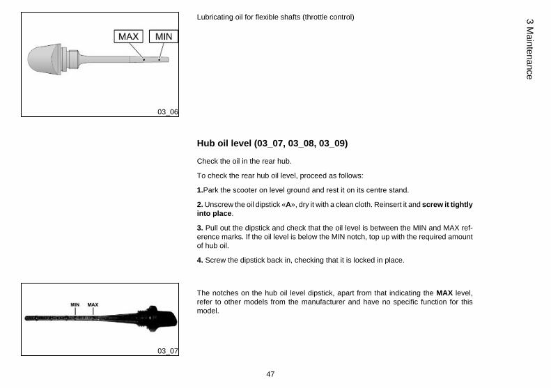
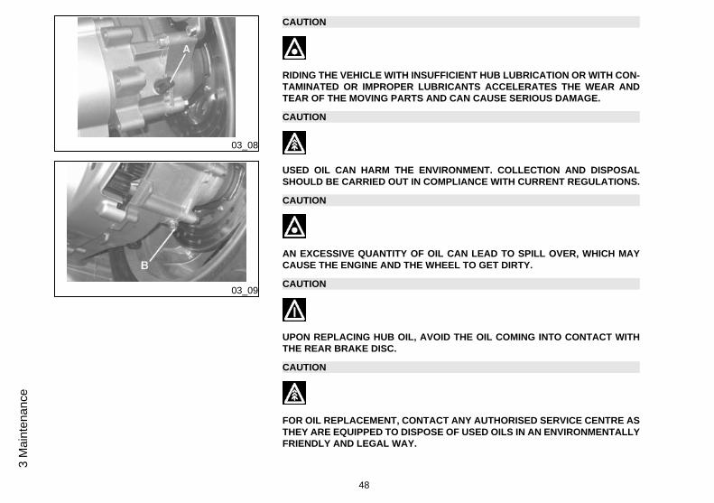
Hub oil level (03_07, 03_08, 03_09)
Check the oil in the rear hub.
To check the rear hub oil level, proceed as follows:
1.Park the scooter on level ground and rest it on its centre stand.
2. Unscrew the oil dipstick «A», dry it with a clean cloth. Reinsert it and screw it tightlyinto place.
3. Pull out the dipstick and check that the oil level is between the MIN and MAX ref-erence marks. If the oil level is below the MIN notch, top up with the required amountof hub oil.
4. Screw the dipstick back in, checking that it is locked in place.
03_07
The notches on the hub oil level dipstick, apart from that indicating the MAX level,refer to other models from the manufacturer and have no specific function for thismodel.
47
3 Maintenance
03_08
03_09
CAUTION
RIDING THE VEHICLE WITH INSUFFICIENT HUB LUBRICATION OR WITH CON-TAMINATED OR IMPROPER LUBRICANTS ACCELERATES THE WEAR ANDTEAR OF THE MOVING PARTS AND CAN CAUSE SERIOUS DAMAGE.
CAUTION
USED OIL CAN HARM THE ENVIRONMENT. COLLECTION AND DISPOSALSHOULD BE CARRIED OUT IN COMPLIANCE WITH CURRENT REGULATIONS.
CAUTION
AN EXCESSIVE QUANTITY OF OIL CAN LEAD TO SPILL OVER, WHICH MAYCAUSE THE ENGINE AND THE WHEEL TO GET DIRTY.
CAUTION
UPON REPLACING HUB OIL, AVOID THE OIL COMING INTO CONTACT WITHTHE REAR BRAKE DISC.
CAUTION
FOR OIL REPLACEMENT, CONTACT ANY AUTHORISED SERVICE CENTRE ASTHEY ARE EQUIPPED TO DISPOSE OF USED OILS IN AN ENVIRONMENTALLYFRIENDLY AND LEGAL WAY.
48
3 M
aint
enan
ce
Recommended productsAGIP ROTRA 80W-90
Rear hub oilSAE 80W/90 Oil that exceeds the requirements of API GL3 specifications
CharacteristicQuantity:
approx. 250 cc
03_10
Tyres (03_10)
WARNING
THE WHEELS FITTED WITH TYRES SHOULD ALWAYS BE BALANCED. RIDINGTHE VEHICLE WITH VERY LOW TYRE PRESSURE OR WITH INCORRECTLYBALANCED TYRES CAN LEAD TO DANGEROUS STEERING VIBRATIONS.
49
3 Maintenance
CAUTION
THE USE OF TYRES OTHER THAN THOSE INDICATED MAY CAUSE INSTABIL-ITY. IT IS HIGHLY ADVISABLE TO USE ORIGINAL PIAGGIO TYRES.
CAUTION
TYRE PRESSURE SHOULD BE CHECKED WHEN TYRES ARE COLD.INCOR-RECT TYRE PRESSURE CAUSES ABNORMAL TYRE WEAR AND MAKES RID-ING DANGEROUS.
TYRES MUST BE REPLACED WHEN THE TREAD REACHES THE WEAR LIMITSSET FORTH BY LAW.
CharacteristicFront tyre pressure
2.2 bar
Rear tyre pressure
2.4 bar
Rear wheel pressure (rider and passenger):
2.5 bar
50
3 M
aint
enan
ce
03_11
03_12
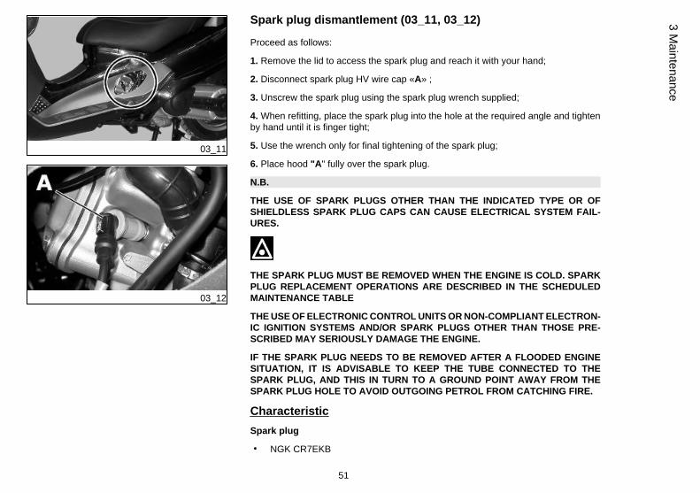
Spark plug dismantlement (03_11, 03_12)
Proceed as follows:
1. Remove the lid to access the spark plug and reach it with your hand;
2. Disconnect spark plug HV wire cap «A» ;
3. Unscrew the spark plug using the spark plug wrench supplied;
4. When refitting, place the spark plug into the hole at the required angle and tightenby hand until it is finger tight;
5. Use the wrench only for final tightening of the spark plug;
6. Place hood "A" fully over the spark plug.
N.B.
THE USE OF SPARK PLUGS OTHER THAN THE INDICATED TYPE OR OFSHIELDLESS SPARK PLUG CAPS CAN CAUSE ELECTRICAL SYSTEM FAIL-URES.
THE SPARK PLUG MUST BE REMOVED WHEN THE ENGINE IS COLD. SPARKPLUG REPLACEMENT OPERATIONS ARE DESCRIBED IN THE SCHEDULEDMAINTENANCE TABLE
THE USE OF ELECTRONIC CONTROL UNITS OR NON-COMPLIANT ELECTRON-IC IGNITION SYSTEMS AND/OR SPARK PLUGS OTHER THAN THOSE PRE-SCRIBED MAY SERIOUSLY DAMAGE THE ENGINE.
IF THE SPARK PLUG NEEDS TO BE REMOVED AFTER A FLOODED ENGINESITUATION, IT IS ADVISABLE TO KEEP THE TUBE CONNECTED TO THESPARK PLUG, AND THIS IN TURN TO A GROUND POINT AWAY FROM THESPARK PLUG HOLE TO AVOID OUTGOING PETROL FROM CATCHING FIRE.
CharacteristicSpark plug
• NGK CR7EKB
51
3 Maintenance
• Champion RG6YCElectrode gap
0.7-0.8 mm
Locking torques (N*m)spark plug
12 to 14 Nm
03_13
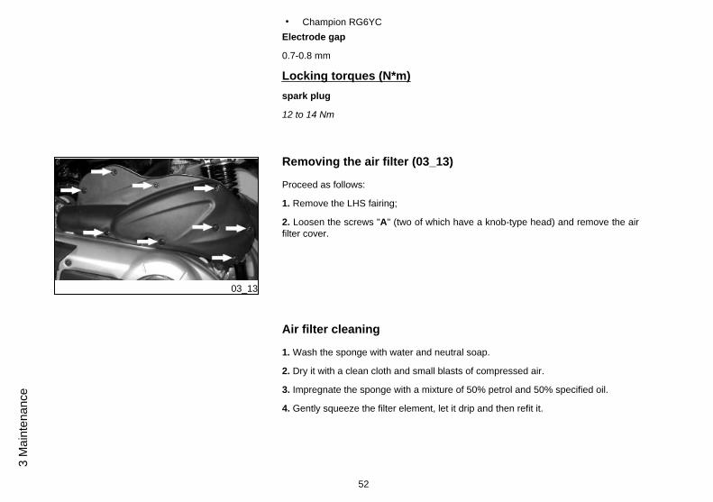
Removing the air filter (03_13)
Proceed as follows:
1. Remove the LHS fairing;
2. Loosen the screws "A" (two of which have a knob-type head) and remove the airfilter cover.
Air filter cleaning
1. Wash the sponge with water and neutral soap.
2. Dry it with a clean cloth and small blasts of compressed air.
3. Impregnate the sponge with a mixture of 50% petrol and 50% specified oil.
4. Gently squeeze the filter element, let it drip and then refit it.
52
3 M
aint
enan
ce
CAUTION
IF THE VEHICLE IS USED ON DUSTY ROADS, IT IS NECESSARY TO SERVICETHE AIR FILTER MORE OFTEN TO AVOID DAMAGING THE ENGINE.
Recommended productsAGIP FILTER OIL
Oil for air filter spongeMineral oil with specific additives for increased adhesiveness
03_14
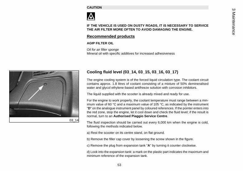
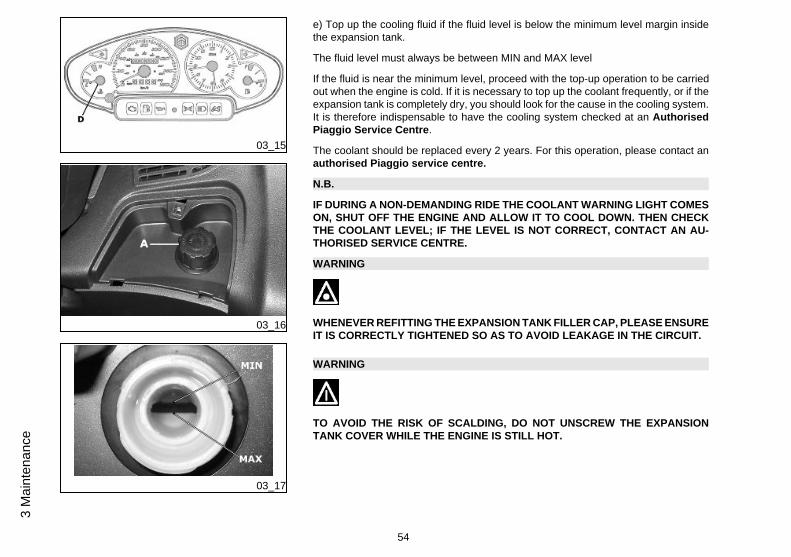
Cooling fluid level (03_14, 03_15, 03_16, 03_17)
The engine cooling system is of the forced liquid circulation type. The coolant circuitcontains approx. 1.8 litres of coolant consisting of a mixture of 50% demineralisedwater and glycol ethylene-based antifreeze solution with corrosion inhibitors.
The liquid supplied with the scooter is already mixed and ready for use.
For the engine to work properly, the coolant temperature must range between a min-imum value of 60 °C and a maximum value of 105 °C, as indicated by the instrument"D" on the analogue instrument panel by coloured references. If the pointer enters intothe red zone, stop the engine, let it cool down and check the fluid level; if the result isnormal, turn to an Authorised Piaggio Service Centre.
The fluid inspection should be carried out every 6,000 km when the engine is cold,following the methods indicated below.
a) Rest the scooter on its centre stand, on flat ground.
b) Remove the filler cap cover by loosening the screw shown in the figure.
c) Remove the plug from expansion tank "A" by turning it counter clockwise.
d) Look into the expansion tank: a mark on the plastic part indicates the maximum andminimum reference of the expansion tank.
53
3 Maintenance
03_15
03_16
03_17
e) Top up the cooling fluid if the fluid level is below the minimum level margin insidethe expansion tank.
The fluid level must always be between MIN and MAX level
If the fluid is near the minimum level, proceed with the top-up operation to be carriedout when the engine is cold. If it is necessary to top up the coolant frequently, or if theexpansion tank is completely dry, you should look for the cause in the cooling system.It is therefore indispensable to have the cooling system checked at an AuthorisedPiaggio Service Centre.
The coolant should be replaced every 2 years. For this operation, please contact anauthorised Piaggio service centre.
N.B.
IF DURING A NON-DEMANDING RIDE THE COOLANT WARNING LIGHT COMESON, SHUT OFF THE ENGINE AND ALLOW IT TO COOL DOWN. THEN CHECKTHE COOLANT LEVEL; IF THE LEVEL IS NOT CORRECT, CONTACT AN AU-THORISED SERVICE CENTRE.
WARNING
WHENEVER REFITTING THE EXPANSION TANK FILLER CAP, PLEASE ENSUREIT IS CORRECTLY TIGHTENED SO AS TO AVOID LEAKAGE IN THE CIRCUIT.
WARNING
TO AVOID THE RISK OF SCALDING, DO NOT UNSCREW THE EXPANSIONTANK COVER WHILE THE ENGINE IS STILL HOT.
54
3 M
aint
enan
ce
WARNING
IN ORDER TO AVOID HARMFUL FLUID LEAKS WHILE RIDING, IT IS IMPORTANTTO MAKE SURE THAT THE LEVEL NEVER EXCEEDS THE MAXIMUM VALUE.
IN ORDER TO GUARANTEE THE PROPER FUNCTION OF THE ENGINE, IT ISNECESSARY TO KEEP THE RADIATOR GRILLE CLEAN.
Recommended productsAGIP PERMANENT SPEZIAL
coolantMonoethylene glycol-based antifreeze fluid, CUNA NC 956-16
03_18
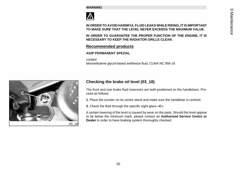
Checking the brake oil level (03_18)
The front and rear brake fluid reservoirs are both positioned on the handlebars. Pro-ceed as follows:
1. Place the scooter on its centre stand and make sure the handlebar is centred;
2. Check the fluid through the specific sight glass «C».
A certain lowering of the level is caused by wear on the pads. Should the level appearto be below the minimum mark, please contact an Authorised Service Centre orDealer in order to have braking system thoroughly checked.
55
3 Maintenance
03_19
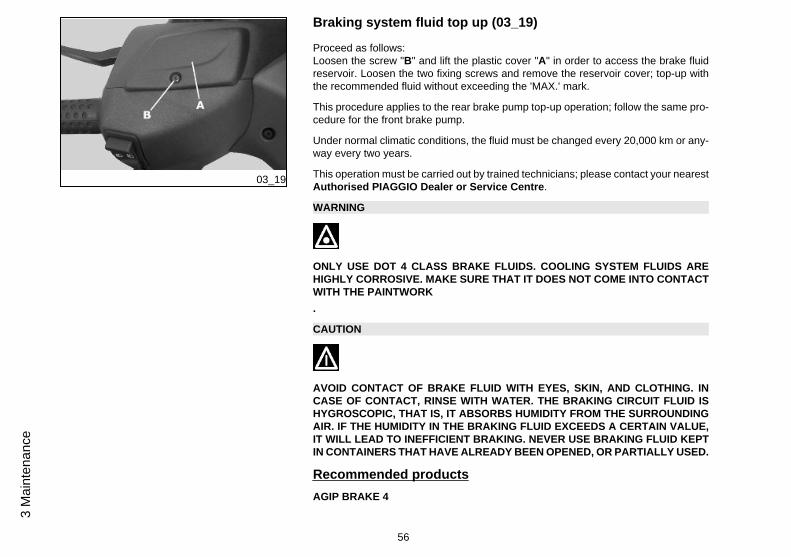
Braking system fluid top up (03_19)
Proceed as follows:Loosen the screw "B" and lift the plastic cover "A" in order to access the brake fluidreservoir. Loosen the two fixing screws and remove the reservoir cover; top-up withthe recommended fluid without exceeding the 'MAX.' mark.
This procedure applies to the rear brake pump top-up operation; follow the same pro-cedure for the front brake pump.
Under normal climatic conditions, the fluid must be changed every 20,000 km or any-way every two years.
This operation must be carried out by trained technicians; please contact your nearestAuthorised PIAGGIO Dealer or Service Centre.
WARNING
ONLY USE DOT 4 CLASS BRAKE FLUIDS. COOLING SYSTEM FLUIDS AREHIGHLY CORROSIVE. MAKE SURE THAT IT DOES NOT COME INTO CONTACTWITH THE PAINTWORK.
CAUTION
AVOID CONTACT OF BRAKE FLUID WITH EYES, SKIN, AND CLOTHING. INCASE OF CONTACT, RINSE WITH WATER. THE BRAKING CIRCUIT FLUID ISHYGROSCOPIC, THAT IS, IT ABSORBS HUMIDITY FROM THE SURROUNDINGAIR. IF THE HUMIDITY IN THE BRAKING FLUID EXCEEDS A CERTAIN VALUE,IT WILL LEAD TO INEFFICIENT BRAKING. NEVER USE BRAKING FLUID KEPTIN CONTAINERS THAT HAVE ALREADY BEEN OPENED, OR PARTIALLY USED.
Recommended productsAGIP BRAKE 4
56
3 M
aint
enan
ce
Brake fluidFMVSS DOT 4 Synthetic fluid
03_20
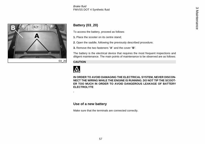
Battery (03_20)
To access the battery, proceed as follows:
1. Place the scooter on its centre stand;
2. Open the saddle, following the previously described procedure;
3. Remove the two fasteners "A" and the cover "B".
The battery is the electrical device that requires the most frequent inspections anddiligent maintenance. The main points of maintenance to be observed are as follows:
CAUTION
IN ORDER TO AVOID DAMAGING THE ELECTRICAL SYSTEM, NEVER DISCON-NECT THE WIRING WHILE THE ENGINE IS RUNNING. DO NOT TIP THE SCOOT-ER TOO MUCH IN ORDER TO AVOID DANGEROUS LEAKAGE OF BATTERYELECTROLYTE.
Use of a new battery
Make sure that the terminals are connected correctly.
57
3 Maintenance
CAUTION
DO NOT REVERSE THE POLARITY: RISK OF SHORT CIRCUIT AND DAMAGETO THE ELECTRICAL SYSTEM.
WARNING
SPENT BATTERIES ARE HARMFUL FOR THE ENVIRONMENT. COLLECTIONAND DISPOSAL SHOULD BE CARRIED OUT IN COMPLIANCE WITH CURRENTREGULATIONS.
Checking the electrolyte level
The electrolyte level, which should be checked regularly, must always be at the max-imum level. To reach this level, use only distilled water. Should it become necessaryto top up the battery with water too frequently, check the scooter's electrical systembecause the battery is being overloaded, causing it to lose power quickly.
CAUTION
ELECTROLYTE CONTAINS SULPHURIC ACID: AVOID CONTACT WITH EYES,SKIN AND CLOTHES. IN THE CASE OF ACCIDENTAL CONTACT, RINSE WITHABUNDANT OF WATER AND CONSULT A DOCTOR.
58
3 M
aint
enan
ce
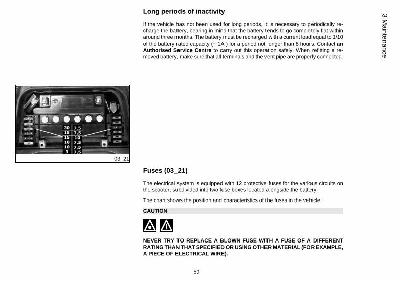
Long periods of inactivity
If the vehicle has not been used for long periods, it is necessary to periodically re-charge the battery, bearing in mind that the battery tends to go completely flat withinaround three months. The battery must be recharged with a current load equal to 1/10of the battery rated capacity (~ 1A ) for a period not longer than 8 hours. Contact anAuthorised Service Centre to carry out this operation safely. When refitting a re-moved battery, make sure that all terminals and the vent pipe are properly connected.
03_21
Fuses (03_21)
The electrical system is equipped with 12 protective fuses for the various circuits onthe scooter, subdivided into two fuse boxes located alongside the battery.
The chart shows the position and characteristics of the fuses in the vehicle.
CAUTION
NEVER TRY TO REPLACE A BLOWN FUSE WITH A FUSE OF A DIFFERENTRATING THAN THAT SPECIFIED OR USING OTHER MATERIAL (FOR EXAMPLE,A PIECE OF ELECTRICAL WIRE).
59
3 Maintenance
BESIDES, IF AFTER REPLACING A FUSE, THE NEW FUSE ALSO BLOWS, THESCOOTER NEEDS TO BE TAKEN TO AN AUTHORISED PIAGGIO/GILERA SERV-ICE CENTRE TO IDENTIFY THE CAUSE OF THE FAULT AND AVOID FURTHERDAMAGE TO THE ELECTRIC SYSTEM COMPONENTS OR THE VEHICLE IT-SELF.
CAUTION
MODIFICATIONS OR REPAIRS TO THE ELECTRICAL SYSTEM, PERFORMEDINCORRECTLY OR WITHOUT STRICT ATTENTION TO THE TECHNICAL SPEC-IFICATIONS OF THE SYSTEM, CAN CAUSE ERRORS IN FUNCTIONING ANDRISK OF FIRE.
FUSE TABLEFuse No. 1 Threshold of operation: 30 A
Location: Battery compartment onthe left side
Protected circuits: Batterycharge
Fuse No. 2 Threshold of operation: 15A
Location: Battery compartment onthe left side
Protected circuits: Linesprotected by fuses 8, 9, 10,12 -Engine stop remote control
60
3 M
aint
enan
ce
Fuse No. 3 Threshold of operation: 15A
Location: Battery compartment onthe left side
Protected circuits: 12V 180Wsocket - Wiring for anti-theft device- Electrical fan remote control -Saddle opening control unit -Actuator for opening saddle andglove-box
Fuse No. 4 Threshold of operation: 10 A
Location: Battery compartment onthe left side
Protected circuits: Remotecontrol for injection components(fuel pump, injector, h.v. coil.)
Fuse No. 5 Threshold of operation: 10 A
Location: Battery compartment onthe left side
Protected circuits: Headlightremote control - Bulb for helmetcompartment light - Warning lightfor saddle/rear compartment coveropen
Fuse No. 6 Threshold of operation: 3 A
Location: Battery compartment onthe left side
Protected circuits: Ignition ECU -Immobilizer decoder
61
3 Maintenance
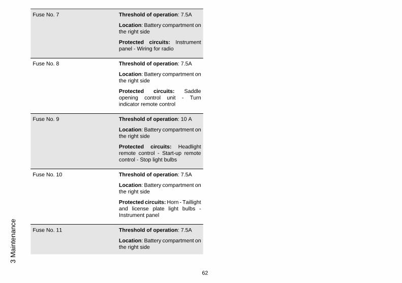
Fuse No. 7 Threshold of operation: 7.5A
Location: Battery compartment onthe right side
Protected circuits: Instrumentpanel - Wiring for radio
Fuse No. 8 Threshold of operation: 7.5A
Location: Battery compartment onthe right side
Protected circuits: Saddleopening control unit - Turnindicator remote control
Fuse No. 9 Threshold of operation: 10 A
Location: Battery compartment onthe right side
Protected circuits: Headlightremote control - Start-up remotecontrol - Stop light bulbs
Fuse No. 10 Threshold of operation: 7.5A
Location: Battery compartment onthe right side
Protected circuits: Horn - Taillightand license plate light bulbs -Instrument panel
Fuse No. 11 Threshold of operation: 7.5A
Location: Battery compartment onthe right side
62
3 M
aint
enan
ce
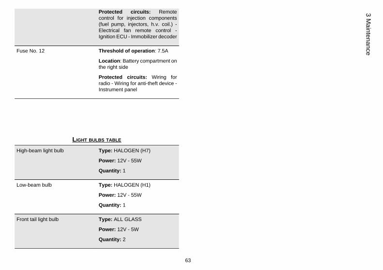
Protected circuits: Remotecontrol for injection components(fuel pump, injectors, h.v. coil.) -Electrical fan remote control -Ignition ECU - Immobilizer decoder
Fuse No. 12 Threshold of operation: 7.5A
Location: Battery compartment onthe right side
Protected circuits: Wiring forradio - Wiring for anti-theft device -Instrument panel
LIGHT BULBS TABLE
High-beam light bulb Type: HALOGEN (H7)
Power: 12V - 55W
Quantity: 1
Low-beam bulb Type: HALOGEN (H1)
Power: 12V - 55W
Quantity: 1
Front tail light bulb Type: ALL GLASS
Power: 12V - 5W
Quantity: 2
63
3 Maintenance
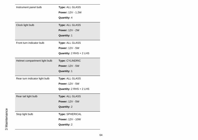
Instrument panel bulb Type: ALL GLASS
Power: 12V - 1.2W
Quantity: 4
Clock light bulb Type: ALL GLASS
Power: 12V - 2W
Quantity: 1
Front turn indicator bulb Type: ALL GLASS
Power: 12V - 5W
Quantity: 2 RHS + 2 LHS
Helmet compartment light bulb Type: CYLINDRIC
Power: 12V - 5W
Quantity: 1
Rear turn indicator light bulb Type: ALL GLASS
Power: 12V - 5W
Quantity: 2 RHS + 2 LHS
Rear tail light bulb Type: ALL GLASS
Power: 12V - 5W
Quantity: 2
Stop light bulb Type: SPHERICAL
Power: 12V - 10W
Quantity: 2
64
3 M
aint
enan
ce
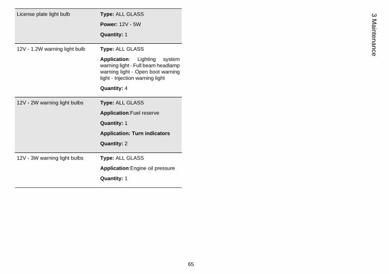
License plate light bulb Type: ALL GLASS
Power: 12V - 5W
Quantity: 1
12V - 1.2W warning light bulb Type: ALL GLASS
Application: Lighting systemwarning light - Full beam headlampwarning light - Open boot warninglight - Injection warning light
Quantity: 4
12V - 2W warning light bulbs Type: ALL GLASS
Application:Fuel reserve
Quantity: 1
Application: Turn indicators
Quantity: 2
12V - 3W warning light bulbs Type: ALL GLASS
Application:Engine oil pressure
Quantity: 1
65
3 Maintenance
03_22
03_23
03_24
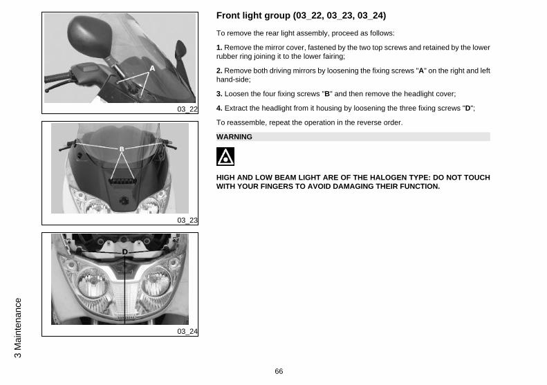
Front light group (03_22, 03_23, 03_24)
To remove the rear light assembly, proceed as follows:
1. Remove the mirror cover, fastened by the two top screws and retained by the lowerrubber ring joining it to the lower fairing;
2. Remove both driving mirrors by loosening the fixing screws "A" on the right and lefthand-side;
3. Loosen the four fixing screws "B" and then remove the headlight cover;
4. Extract the headlight from it housing by loosening the three fixing screws "D";
To reassemble, repeat the operation in the reverse order.
WARNING
HIGH AND LOW BEAM LIGHT ARE OF THE HALOGEN TYPE: DO NOT TOUCHWITH YOUR FINGERS TO AVOID DAMAGING THEIR FUNCTION.
66
3 M
aint
enan
ce
03_25
03_26
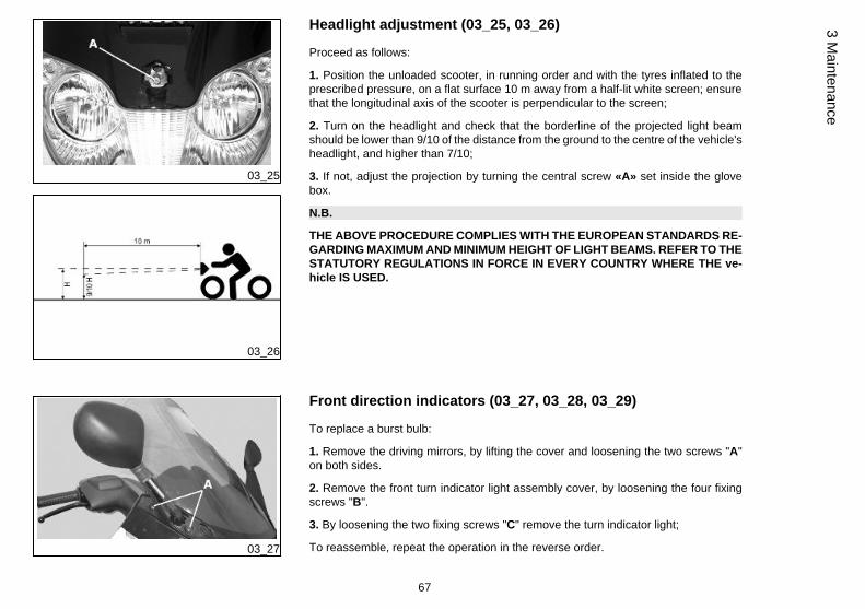
Headlight adjustment (03_25, 03_26)
Proceed as follows:
1. Position the unloaded scooter, in running order and with the tyres inflated to theprescribed pressure, on a flat surface 10 m away from a half-lit white screen; ensurethat the longitudinal axis of the scooter is perpendicular to the screen;
2. Turn on the headlight and check that the borderline of the projected light beamshould be lower than 9/10 of the distance from the ground to the centre of the vehicle'sheadlight, and higher than 7/10;
3. If not, adjust the projection by turning the central screw «A» set inside the glovebox.
N.B.
THE ABOVE PROCEDURE COMPLIES WITH THE EUROPEAN STANDARDS RE-GARDING MAXIMUM AND MINIMUM HEIGHT OF LIGHT BEAMS. REFER TO THESTATUTORY REGULATIONS IN FORCE IN EVERY COUNTRY WHERE THE ve-hicle IS USED.
03_27
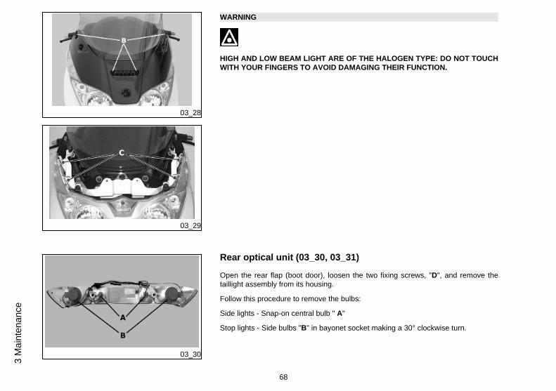
Front direction indicators (03_27, 03_28, 03_29)
To replace a burst bulb:
1. Remove the driving mirrors, by lifting the cover and loosening the two screws "A"on both sides.
2. Remove the front turn indicator light assembly cover, by loosening the four fixingscrews "B".
3. By loosening the two fixing screws "C" remove the turn indicator light;
To reassemble, repeat the operation in the reverse order.
67
3 Maintenance
03_28
03_29
WARNING
HIGH AND LOW BEAM LIGHT ARE OF THE HALOGEN TYPE: DO NOT TOUCHWITH YOUR FINGERS TO AVOID DAMAGING THEIR FUNCTION.
03_30
Rear optical unit (03_30, 03_31)
Open the rear flap (boot door), loosen the two fixing screws, "D", and remove thetaillight assembly from its housing.
Follow this procedure to remove the bulbs:
Side lights - Snap-on central bulb " A"
Stop lights - Side bulbs "B" in bayonet socket making a 30° clockwise turn.
68
3 M
aint
enan
ce
03_31
Rear turn indicators (03_31)
Detach the taillight to reach the fixing screw of the turn indicator.
Detach the rubber bulb holder and slide the burned out bulb off the bayonet joint.
03_32
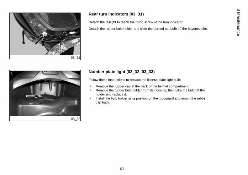
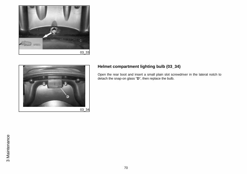
Number plate light (03_32, 03_33)
Follow these instructions to replace the license plate light bulb:
• Remove the rubber cap at the back of the helmet compartment.• Remove the rubber bulb holder from its housing; then take the bulb off the
holder and replace it.• Install the bulb holder in its position on the mudguard and mount the rubber
cap back.
69
3 Maintenance
03_33
03_34
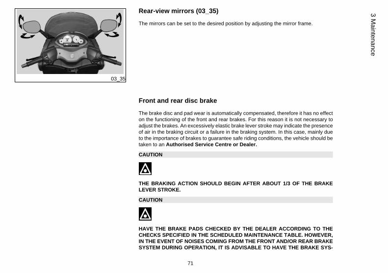
Helmet compartment lighting bulb (03_34)
Open the rear boot and insert a small plain slot screwdriver in the lateral notch todetach the snap-on glass "D", then replace the bulb.
70
3 M
aint
enan
ce
03_35
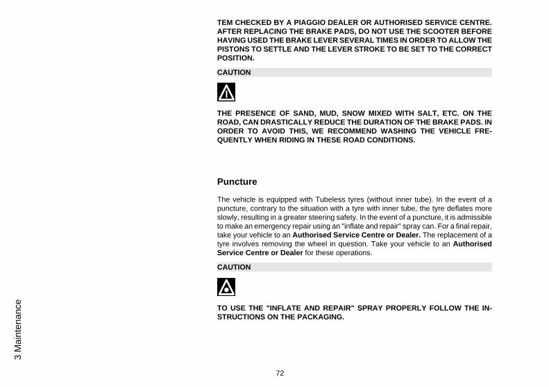
Rear-view mirrors (03_35)
The mirrors can be set to the desired position by adjusting the mirror frame.
Front and rear disc brake
The brake disc and pad wear is automatically compensated, therefore it has no effecton the functioning of the front and rear brakes. For this reason it is not necessary toadjust the brakes. An excessively elastic brake lever stroke may indicate the presenceof air in the braking circuit or a failure in the braking system. In this case, mainly dueto the importance of brakes to guarantee safe riding conditions, the vehicle should betaken to an Authorised Service Centre or Dealer.
CAUTION
THE BRAKING ACTION SHOULD BEGIN AFTER ABOUT 1/3 OF THE BRAKELEVER STROKE.
CAUTION
HAVE THE BRAKE PADS CHECKED BY THE DEALER ACCORDING TO THECHECKS SPECIFIED IN THE SCHEDULED MAINTENANCE TABLE. HOWEVER,IN THE EVENT OF NOISES COMING FROM THE FRONT AND/OR REAR BRAKESYSTEM DURING OPERATION, IT IS ADVISABLE TO HAVE THE BRAKE SYS-
71
3 Maintenance
TEM CHECKED BY A PIAGGIO DEALER OR AUTHORISED SERVICE CENTRE.AFTER REPLACING THE BRAKE PADS, DO NOT USE THE SCOOTER BEFOREHAVING USED THE BRAKE LEVER SEVERAL TIMES IN ORDER TO ALLOW THEPISTONS TO SETTLE AND THE LEVER STROKE TO BE SET TO THE CORRECTPOSITION.
CAUTION
THE PRESENCE OF SAND, MUD, SNOW MIXED WITH SALT, ETC. ON THEROAD, CAN DRASTICALLY REDUCE THE DURATION OF THE BRAKE PADS. INORDER TO AVOID THIS, WE RECOMMEND WASHING THE VEHICLE FRE-QUENTLY WHEN RIDING IN THESE ROAD CONDITIONS.
Puncture
The vehicle is equipped with Tubeless tyres (without inner tube). In the event of apuncture, contrary to the situation with a tyre with inner tube, the tyre deflates moreslowly, resulting in a greater steering safety. In the event of a puncture, it is admissibleto make an emergency repair using an "inflate and repair" spray can. For a final repair,take your vehicle to an Authorised Service Centre or Dealer. The replacement of atyre involves removing the wheel in question. Take your vehicle to an AuthorisedService Centre or Dealer for these operations.
CAUTION
TO USE THE "INFLATE AND REPAIR" SPRAY PROPERLY FOLLOW THE IN-STRUCTIONS ON THE PACKAGING.
72
3 M
aint
enan
ce
WARNING
THE WHEELS FITTED WITH TYRES SHOULD ALWAYS BE BALANCED. RIDINGTHE VEHICLE WITH VERY LOW TYRE PRESSURE OR WITH INCORRECTLYBALANCED TYRES CAN LEAD TO DANGEROUS STEERING VIBRATIONS.
03_36
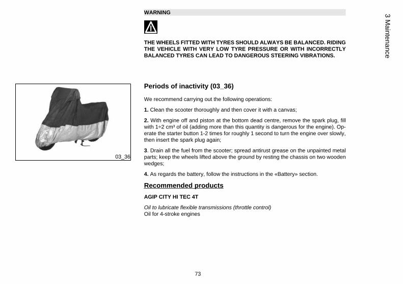
Periods of inactivity (03_36)
We recommend carrying out the following operations:
1. Clean the scooter thoroughly and then cover it with a canvas;
2. With engine off and piston at the bottom dead centre, remove the spark plug, fillwith 1÷2 cm³ of oil (adding more than this quantity is dangerous for the engine). Op-erate the starter button 1-2 times for roughly 1 second to turn the engine over slowly,then insert the spark plug again;
3. Drain all the fuel from the scooter; spread antirust grease on the unpainted metalparts; keep the wheels lifted above the ground by resting the chassis on two woodenwedges;
4. As regards the battery, follow the instructions in the «Battery» section.
Recommended productsAGIP CITY HI TEC 4T
Oil to lubricate flexible transmissions (throttle control)Oil for 4-stroke engines
73
3 Maintenance
Cleaning the vehicle
In order to soften the dirt and mud deposited on the painted surfaces, use a low pres-sure jet of water. Once softened, mud and dirt must be removed with a soft spongefor bodywork soaked in lots of water and "shampoo" (2-4% of car shampoo in water).Then rinse abundantly with water, and dry with a shammy cloth. For the outside of theengine, use petroleum, a brush and clean cloths. Petroleum can damage paintwork.Remember that any polishing with silicone wax must always be preceded by washing
CAUTION
DETERGENTS CAN POLLUTE WATER. THE VEHICLE MUST BE WASHED AT AWASH STATION EQUIPPED WITH A SPECIAL WATER PURIFICATION SYSTEM.
CAUTION
PER IL LAVAGGIO DEL MOTORE E DEL VEICOLO É SCONSIGLIATO L'UTILIZ-ZO DELL'IDROPULITRICE; NEL CASO CHE NON SIA POSSIBILE EFFETTUARETALE OPERAZIONE IN UN ALTRO MODO, É NECESSARIO:• USARE SOLAMENTE IL GETTO A VENTAGLIO.
• NON AVVICINARE LA LANCIA A MENO DI 2 FT (60 CM).
• NON USARE ACQUA A TEMPERATURE SUPERIORI A 100° F (40°C).
• NON UTILIZZARE IL GETTO AD ALTA PRESSIONE.
• NON UTILIZZARE IL LAVAGGIO A VAPORE.
• NON INDIRIZZARE IL GETTO DIRETTAMENTE VERSO: IL MOTORE, I CA-BLAGGI ELETTRICI, LE FERITOIE DI RAFFREDDAMENTO DEL COPERCHIOTRASMISSIONE E DEL COPERCHIO CHIOCCIOLA.
74
3 M
aint
enan
ce
CAUTION
NEVER WASH THE SCOOTER IN DIRECT SUNLIGHT, ESPECIALLY IN SUMMERWHEN THE BODYWORK IS STILL HOT AS THE SHAMPOO COULD DAMAGETHE PAINTWORK IF IT DRIES BEFORE BEING RINSED OFF. NEVER USECLOTHS SOAKED IN ALCOHOL, PETROL, DIESEL OIL OR KEROSENE FORCLEANING THE PAINTED OR PLASTIC SURFACES, IN ORDER NOT TO DAM-AGE THE LUSTRE FINISH OR ALTER THE MECHANICAL PROPERTIES. USINGSILICONE-BASED WAX CAN DAMAGE THE PAINTED SURFACES, DEPENDINGON THE VEHICLE COLOUR (SATIN COLOURS). FOR FURTHER INFORMATIONON THIS MATTER, CONTACT AN AUTHORISED SERVICE CENTRE .
STARTING FAILUREEmergency switch in «OFF» Set the switch back to «ON»
Fuse blown Replace the blown fuse and havethe vehicle checked by anAuthorised Service Centre.
STARTING DIFFICULTIES (SEE «START-UPPROBLEMS» SECTION)
Lack of fuel in tank. Refuelling
Injection system fault Contact an Authorised ServiceCentre
75
3 Maintenance
Faulty fuel pump Contact an Authorised ServiceCentre
Battery flat Recharge the battery.
* IMPORTANT: DO NOT USE THE SCOOTER TO THE COMPLETEEXHAUSTION OF FUEL; SHOULD THIS OCCUR, DO NOTATTEMPT TO START THE ENGINE. TURN THE KEY SWITCH TO«OFF» AND TOP-UP THE FUEL TANK AS SOON AS POSSIBLE.FAILURE TO FOLLOW THESE GUIDELINES COULD DAMAGE THEFUEL PUMP AND/OR THE CATALYTIC CONVERTER.
IGNITION PROBLEMSFaulty spark plug Contact an Authorised Service
Centre.
Faulty ignition / injection controlunit. Due to the presence of highvoltage, this check should only becarried out by an expert.
Contact an Authorised ServiceCentre
LACK OF COMPRESSIONLoose spark plug. Screw in the spark plug tightly
Cylinder head loose, piston gasrings worn.
Contact an Authorised ServiceCentre.
Valve stuck Contact an Authorised ServiceCentre.
76
3 M
aint
enan
ce
HIGH CONSUMPTION AND LOW PERFORMANCEClogged or dirty air filter Try to blow out with compressed
air, otherwise replace the filter
INSUFFICIENT BRAKINGGreasy disc. Worn pads. Faultybraking system. Presence of air inthe front and rear brake circuit.
Contact an Authorised ServiceCentre.
INEFFICIENT SUSPENSIONSShock absorber fault, oil leak, endbuffer damaged; shock absorberpreloading incorrectly set
Contact an Authorised ServiceCentre.
IRREGULAR AUTOMATIC TRANSMISSIONVariator rollers and/or driving beltdamaged
Contact an Authorised ServiceCentre.
77
3 Maintenance

78
3 M
aint
enan
ce

X8 400 i.e.
Chap. 04Technical data
79
ENGINE TECHNICAL DATAVersion (400) 400
Engine Single-cylinder, four-stroke, fourvalves, single overhead camshaft,chain driven on the flywheel side
Cubic capacity 399 cm³
Bore x stroke 85.8 X 69 mm
Compression ratio 10.6 ± 0.5 : 1
Idle speed 1500 ± 100 rpm
Maximum torque (to thecrankshaft)
36 Nm at 5500 rpm
Maximum power (to thecrankshaft)
24.5 kW at 7250 rpm
Electronic ignition inductive, high efficiencyintegrated with the injectionsystem, with variable timing andseparate HV coil.
Ignition advance (before TDC) Variable advance controlled by theinjection control unit
Fuel supply 38 Ø mm throttle body and singleinjector
Lubrication Engine lubrication with trochoidalpump (inside the crankcase), oilfilter and pressure adjustment by-pass.
80
4 Te
chni
cal d
ata
Cooling Forced fluid circulation, withengine driven pump; 3-waythermostat to pump intake.
Transmission Automatic expandable pulleyspeed variator, V belt, dry self-ventilating automatic centrifugalclutch, gear reduction unit andtransmission casing with forced aircirculation cooling.
Spark plug • NGK CR7EKB• Champion RG6YC
Valve clearance intake: 0.15 mm discharge (whencold): 0.15 mm (when cold)
Exhaust muffler absorption-type exhaust mufflerwith catalytic converter.
Engine oil (empty) 1.7 lt.
Engine oil (at oil and filter change) 1.5 lt.
Rear hub oil 250 cc
VEHICLE TECHNICAL DATAOverall width 750 mm
Overall length 2190 mm
Overall height 1360 mm
Saddle height 790 mm
Wheelbase 1540 mm
81
4 Technical data
Front suspension Double effect hydraulic telescopicfork with Ø 35 mm stems and pinbackwards with connections fordouble brake calliper
Rear suspension Engine with swinging fork attachedto the frame by means of an armwith one degree of freedom and apair of double effect hydraulicshock absorbers with 4 adjustablepreload positions.
Front brake Ø 240mm double disk brake withhydraulic control activated by thehandlebar right-hand lever.
Rear brake Ø 240 mm disc brake withhydraulic control activated byhandlebar left lever.
Front wheel rim Die-cast aluminium alloy,3.50"x14''
Rear wheel rim Die-cast aluminium alloy 4.50"x14"
Front tyre Tubeless 120/70 - 14'' - MichelinGold Standard M/C 55S
Rear tyre Tubeless 140/70 - 14'' - MichelinGold Standard M/C 68S
Frame Welded tubular steel structure,with asymmetrical frame structure,front beams and union elements instamped sheets.
Kerb weight 206 kg
Maximum load 180 kg.
Cooling system Capacity: approx. 1.8 litres
82
4 Te
chni
cal d
ata
Fuel tank capacity Tank capacity: ~12 l (approximatevalue)
Fuel reserve approx. 2.5 litres (indicative value)
04_01
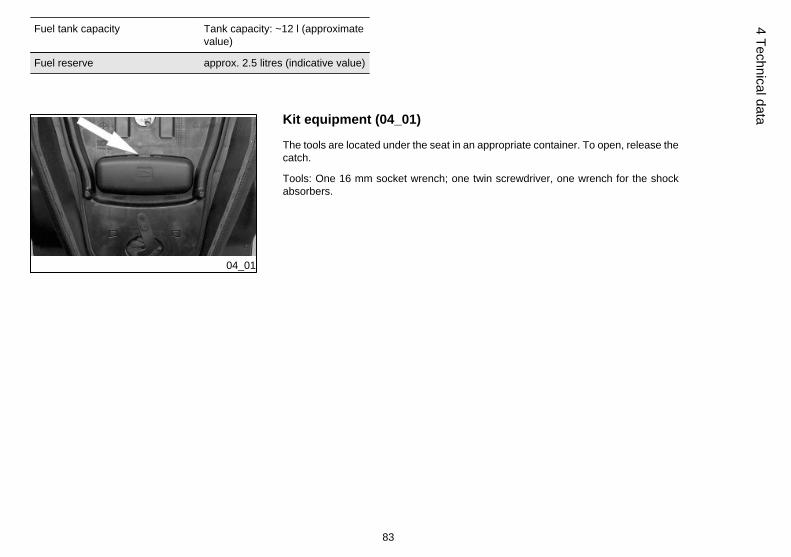
Kit equipment (04_01)
The tools are located under the seat in an appropriate container. To open, release thecatch.
Tools: One 16 mm socket wrench; one twin screwdriver, one wrench for the shockabsorbers.
83
4 Technical data

84
4 Te
chni
cal d
ata

X8 400 i.e.
Chap. 05Spare parts and
accessories
85
05_01
05_02
Warnings (05_01, 05_02)
WARNING
TO PREVENT ACCIDENTS AND TO GUARANTEE PROPER STABILITY, PER-FORMANCE AND SAFETY, RIDE THE VEHICLE VERY CAREFULLY WHEN IT ISFITTED WITH ACCESSORIES OR WITH UNUSUAL LOADS.
WARNING
IT IS ALSO RECOMMENDED THAT "ORIGINAL PIAGGIO SPARE PARTS" BEUSED, AS THESE ARE THE ONLY ONES OFFERING YOU THE SAME QUALITYGUARANTEE AS THOSE INITIALLY FITTED ON THE SCOOTER. THE USE OFNON-ORIGINAL SPARE PARTS RENDERS THE WARRANTY VOID.
WARNING
PIAGGIO MARKETS ITS OWN LINE OF ACCESSORIES THAT ARE RECOG-NISED AND GUARANTEED FOR USE. IT IS THEREFORE ESSENTIAL, IN ORDERTO CHOOSE AND MOUNT THE ACCESSORIES CORRECTLY, TO CONTACT ANAUTHORISED DEALER OR SERVICE CENTRE. THE USE OF NON-ORIGINALACCESSORIES MAY AFFECT THE STABILITY AND OPERATION OF YOUR VE-HICLE AND REDUCE SAFETY LEVELS WITH POTENTIAL RISKS FOR THERIDER.
NEVER RIDE THE SCOOTER FITTED WITH ACCESSORIES (GLOVE-BOX) ATSPEEDS OVER 110 KM/H.
86
5 Sp
are
parts
and
acc
esso
ries
THE SCOOTER CAN BE RIDDEN AT A HIGHER SPEED WITHOUT THE AFORE-MENTIONED ACCESSORIES WITHIN THE LIMITS ESTABLISHED BY LAW.
IF THERE SHOULD BE NON-PIAGGO ACCESSORIES INSTALLED, OR AN AB-NORMAL LOAD, OR IF THE SCOOTER IS NOT IN A GENERALLY GOOD CON-DITION, OR WHENEVER WEATHER CONDITIONS DEMAND IT, SPEED SHOULDBE REDUCED FURTHER.
WARNING
BE EXTREMELY CAREFUL WHEN INSTALLING AND REMOVING THE MECHAN-ICAL ANTI-THEFT DEVICE ON THE VEHICLE ( U-SHAPED PADLOCK, DISKBLOCK, ETC.).
MAINLY NEAR THE BRAKE PIPES, TRANSMISSIONS AND/OR ELECTRIC CA-BLES, AN INCORRECT INSTALLATION OR REMOVAL OF THE ANTI-THEFTDEVICE AS WELL AS LEAVING IT ON BEFORE STARTING THE VEHICLE CANSERIOUSLY DAMAGE ITS COMPONENTS, COMPROMISE THE CORRECTFUNCTIONING OF THE VEHICLE AND USERS' SAFETY.
87
5 Spare parts and accessories

88
5 Sp
are
parts
and
acc
esso
ries
X8 400 i.e.
Chap. 06Programmedmaintenance
89
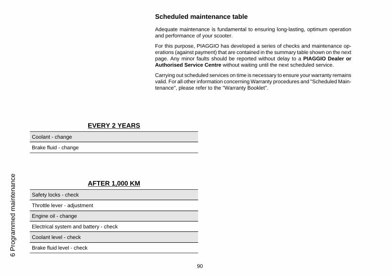
Scheduled maintenance table
Adequate maintenance is fundamental to ensuring long-lasting, optimum operationand performance of your scooter.
For this purpose, PIAGGIO has developed a series of checks and maintenance op-erations (against payment) that are contained in the summary table shown on the nextpage. Any minor faults should be reported without delay to a PIAGGIO Dealer orAuthorised Service Centre without waiting until the next scheduled service.
Carrying out scheduled services on time is necessary to ensure your warranty remainsvalid. For all other information concerning Warranty procedures and "Scheduled Main-tenance", please refer to the "Warranty Booklet".
EVERY 2 YEARSCoolant - change
Brake fluid - change
AFTER 1,000 KMSafety locks - check
Throttle lever - adjustment
Engine oil - change
Electrical system and battery - check
Coolant level - check
Brake fluid level - check
90
6 Pr
ogra
mm
ed m
aint
enan
ce
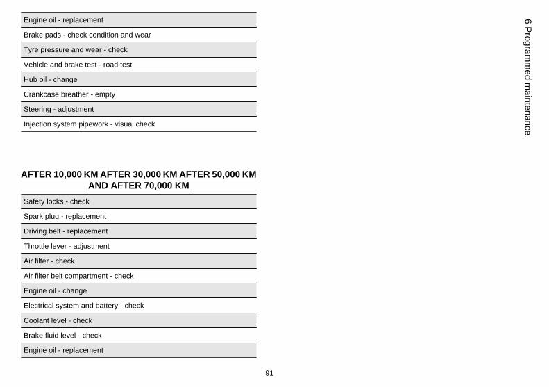
Engine oil - replacement
Brake pads - check condition and wear
Tyre pressure and wear - check
Vehicle and brake test - road test
Hub oil - change
Crankcase breather - empty
Steering - adjustment
Injection system pipework - visual check
AFTER 10,000 KM AFTER 30,000 KM AFTER 50,000 KMAND AFTER 70,000 KM
Safety locks - check
Spark plug - replacement
Driving belt - replacement
Throttle lever - adjustment
Air filter - check
Air filter belt compartment - check
Engine oil - change
Electrical system and battery - check
Coolant level - check
Brake fluid level - check
Engine oil - replacement
91
6 Programm
ed maintenance
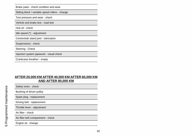
Brake pads - check condition and wear
Sliding block / variable speed rollers - change
Tyre pressure and wear - check
Vehicle and brake test - road test
Hub oil - check
Idle speed (*) - adjustment
Centre/side stand joint - lubrication
Suspensions - check
Steering - Check
Injection system pipework - visual check
Crankcase breather - empty
AFTER 20,000 KM AFTER 40,000 KM AFTER 60,000 KMAND AFTER 80,000 KM
Safety locks - check
Bushing of driven pulley
Spark plug - replacement
Driving belt - replacement
Throttle lever - adjustment
Air filter - check
Air filter belt compartment - check
Engine oil - change
92
6 Pr
ogra
mm
ed m
aint
enan
ce
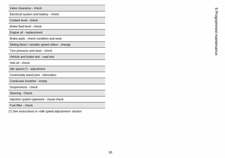
Valve clearance - check
Electrical system and battery - check
Coolant level - check
Brake fluid level - check
Engine oil - replacement
Brake pads - check condition and wear
Sliding block / variable speed rollers - change
Tyre pressure and wear - check
Vehicle and brake test - road test
Hub oil - check
Idle speed (*) - adjustment
Centre/side stand joint - lubrication
Crankcase breather - empty
Suspensions - check
Steering - Check
Injection system pipework - visual check
Fuel filter - check
(*) See instructions in «Idle speed adjustment» section
93
6 Programm
ed maintenance
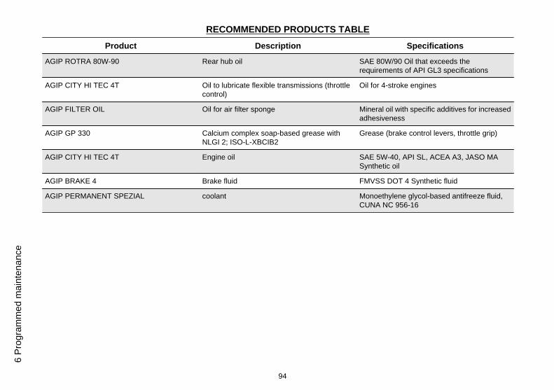
RECOMMENDED PRODUCTS TABLEProduct Description Specifications
AGIP ROTRA 80W-90 Rear hub oil SAE 80W/90 Oil that exceeds therequirements of API GL3 specifications
AGIP CITY HI TEC 4T Oil to lubricate flexible transmissions (throttlecontrol)
Oil for 4-stroke engines
AGIP FILTER OIL Oil for air filter sponge Mineral oil with specific additives for increasedadhesiveness
AGIP GP 330 Calcium complex soap-based grease withNLGI 2; ISO-L-XBCIB2
Grease (brake control levers, throttle grip)
AGIP CITY HI TEC 4T Engine oil SAE 5W-40, API SL, ACEA A3, JASO MASynthetic oil
AGIP BRAKE 4 Brake fluid FMVSS DOT 4 Synthetic fluid
AGIP PERMANENT SPEZIAL coolant Monoethylene glycol-based antifreeze fluid,CUNA NC 956-16
94
6 Pr
ogra
mm
ed m
aint
enan
ce
TABLE OF CONTENTS
AAir filter: 52
BBattery: 57Brake: 55, 71
CClock: 10
DDisc brake: 71
EEngine oil: 44–46Engine stop: 13
FFuses: 59
HHeadlight: 67Horn: 12Hub oil: 47
IIdentification: 23Immobilizer: 13, 16Instrument panel: 9
KKey switch: 10Keys: 14
LLight switch: 12
MMaintenance: 43, 89, 90Mirrors: 71
SSaddle: 18, 20–22Scheduled maintenance: 90Shock absorbers: 31Spark plug: 51Stand: 37Start-up: 13
TTechnical Data: 79Top box: 24Transmission: 38Turn indicators: 69Tyre pressure: 30Tyres: 49
95

The descriptions and illustrations given in this publication are not binding. While the basic specifications as described and illustrated in this manualremain unchanged, PIAGGIO-GILERA reserves the right, at any time and without being required to update this publication beforehand, to make anychanges to components, parts or accessories, which it considers necessary to improve the product or which are required for manufacturing or con-struction reasons.
Not all versions/models shown in this publication are available in all countries. The availability of single versions should be checked at the official Piaggio sales network.
"© Copyright 2007 - PIAGGIO & C. S.p.A. Pontedera. All rights reserved. Reproduction of this publication in whole or in part is prohibited."
PIAGGIO & C. S.p.A. - After-Sales
V.le Rinaldo Piaggio, 23 - 56025 PONTEDERA (Pi)