Embed Size (px)
Citation preview
JinkoSolar Photovoltaic Module
Installation Manual
Contents
1 General Information
2. Installation
1112
55666778
22
24
26
27
27
1.1 Overview
1.2 Applicable Products
1.3 Warnings
2.1 Installation safety
2.2 Installation Condition
2.3 Mechanical Installation introduction
2.2.1 Climate condition
2.2.2 Site selection
2.3.1 Fixation with screws
2.3.5 Fixation with screws & clamps at the long &short sides
2.2.3 Tilt angle selection
3 Wiring and connection
4 Maintenance and care
5 Electrical specification
Edition 10/2015
4.1 Visual Inspection
4.3 Inspection of Connector and Cable
26
286 Disclaimer of Liability
274.2 Cleaning
112.3.2 Fixation with clamps at long sides of frames
162.3.3 Fixation with clamps at short sides of frames
192.3.4 Fixation with clamps at the long & short sides
[键入文字]
- 1 -
1. General Information
1.1 Overview
Thanks for choosing Jinko Solar PV modules. In order to ensure the PV modules to
be installed correctly, please read the following operation instructions carefully before
modules to be installed and used.
Please remember that the products would generate electricity, thus certain safety
measures need to be taken to avoid danger.
1.2 Applicable Products
This document is applicable to the series of solar module as listed below:
With 6” poly and mono c-Si:
JKMxxxP-60/JKMxxxPP-60*/JKMxxxP-60-J/JKMxxxPP-60-J/JKMxxxP-60B/JKMxxx
P-60(Plus)**/JKMxxxPP-60(Plus)/JKMSxxxP-60***/JKMSxxxP-60-J/JKMSxxxP-60(P
lus)/JKMSxxxP-60B****
(XXX=210~280, in increment of 5)
JKMxxxP-72/JKMxxxPP-72/JKMxxxP-72-J/JKMxxxPP-72-J/JKMxxxP-72B/JKMxxxP
-72(Plus)/JKMxxxPP-72(Plus)/JKMSxxxP-72/JKMSxxxP-72-J/JKMSxxxP-72(Plus)/
JKMSxxxP-72B
(XXX=250-340, in increment of 5)
JKMxxxM-60/JKMxxxM-60-J/JKMxxxM-60(Plus)/JKMxxxM-60B/JKMSxxxM-60/JKM
SxxxM-60-J/JKMSxxxM-60(Plus)
(XXX=210~280, in increment of 5)
JKMxxxM-72/JKMxxxM-72-J/JKMxxxM-72(Plus)
/JKMxxxM-72B/JKMSxxxM-72/JKMSxxxM-72-J/JKMSxxxM-72(Plus)
(XXX=250-335, in increment of 5)
- 2 -
JKMxxxP-48/JKMxxxPP-48/JKMxxxP-48-J/JKMxxxPP-48-J/JKMxxxP-48(Plus)/JKM
xxxPP-48(Plus)/JKMSxxxP-48/JKMSxxxP-48-J/JKMSxxxP-48Plus)
(XXX=170~225, in increment of 5)
With 5” mono c-Si:
JKMxxxM-72/JKMxxxM-72-J/JKMxxxM-72B/JKMSxxxM-72/JKMSxxxM-72-J
(XXX=160~215, in increment of 5)
JKMxxxM-96/JKMxxxM-96-J/JKMxxxM-96B/JKMSxxxM-96/JKMSxxxM-96-J
(XXX=210~285, in increment of 5)
Notes:
*PP: the EAGLE Series module
** (Plus):the eagle+ Series module
***JKMS: the smart module
****B: module with black back sheet
Make sure the array of modules installed within the Maximum permitted system
voltage and the rating current and voltage of the sub-equipments such as regulators
and inverters. The maximum permitted system voltage (DC) of the modules sold in
Europe is 1000V
The assembly is to be mounted over a fire resistant roof covering rated for the
application. Before mounting the module, please consult your local building
department to determine approved roofing materials.
The modules are qualified for application class A: Hazardous voltage (IEC 61730:
higher than 50V DC; EN 61730: higher than 120V), hazardous power applications
(higher than 240W) where general contact access is anticipated (Modules qualified
for safety through EN IEC 61730-1 and -2 within this application class are considered
to meet the requirements for Safety Class II.
1.3 Warnings
PV modules generate DC electrical energy when exposed to sunlight or other light sources. Active parts of module such as terminals can result in burns, sparks, and lethal shock. Artificially concentrated sunlight shall not be directed on the module or panel.
- 3 -
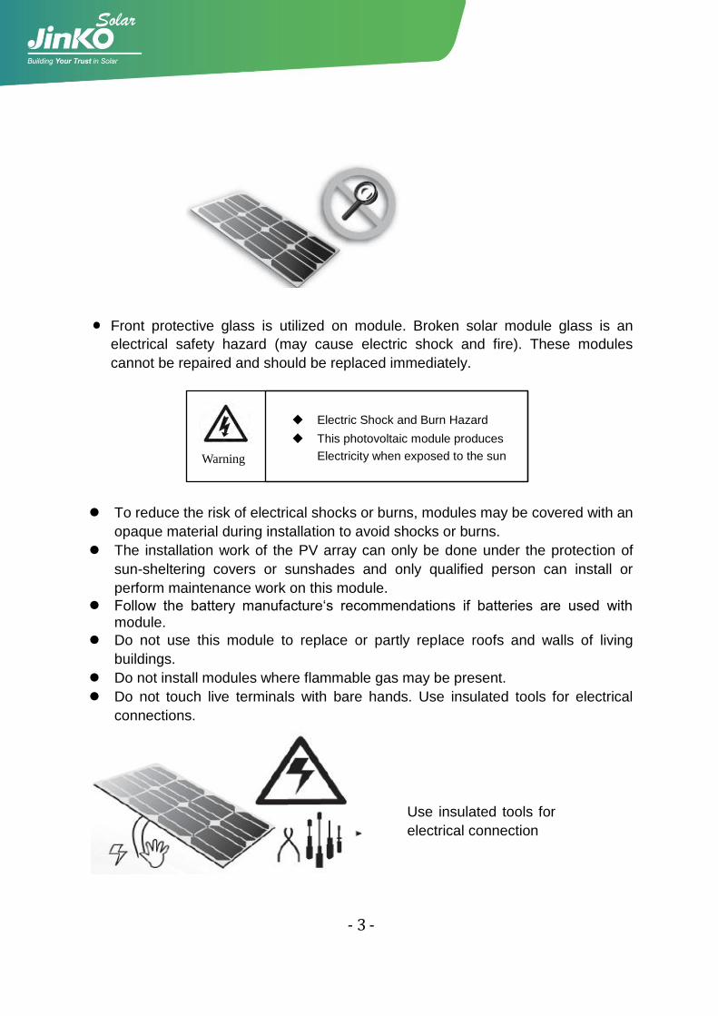
· Front protective glass is utilized on module. Broken solar module glass is an
electrical safety hazard (may cause electric shock and fire). These modules
cannot be repaired and should be replaced immediately.
Electric Shock and Burn Hazard
This photovoltaic module produces
Electricity when exposed to the sun
To reduce the risk of electrical shocks or burns, modules may be covered with an
opaque material during installation to avoid shocks or burns.
The installation work of the PV array can only be done under the protection of
sun-sheltering covers or sunshades and only qualified person can install or
perform maintenance work on this module.
Follow the battery manufacture„s recommendations if batteries are used with module.
Do not use this module to replace or partly replace roofs and walls of living
buildings.
Do not install modules where flammable gas may be present.
Do not touch live terminals with bare hands. Use insulated tools for electrical
connections.
Warning
Use insulated tools for
electrical connection
- 4 -
Do not remove any part installed by Jinko Solar or disassemble the module.
All instructions should be read and understood before attempting to install, wire,
operate and maintain the module.
Please don‟t lift up PV modules using the attached cables or the junction box.
All PV systems must be earthed. If there is no special regulation, please follow
the National Electrical Code or other national code.
Under normal conditions, a photovoltaic module is likely to experience conditions
that produce more current and/or voltage than reported at standard test
conditions. Accordingly, the value of Isc and Voc marked on this module should
be multiplied by 1.25 when determining PV system component voltage ratings,
conductor current ratings, fuse sizes, and size of controls connected to the PV
output.
Once the PV module has been shipped to the installation site, all of the parts
should be unpacked properly with care.
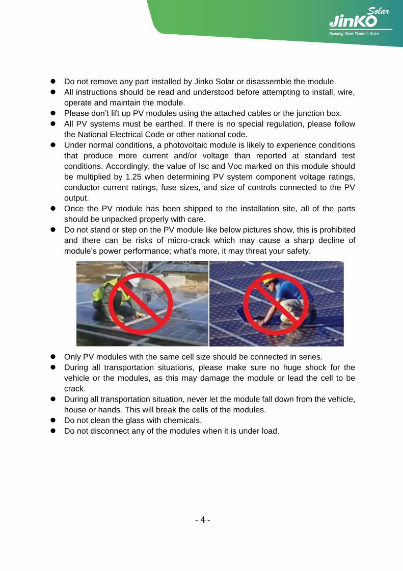
Do not stand or step on the PV module like below pictures show, this is prohibited
and there can be risks of micro-crack which may cause a sharp decline of
module‟s power performance; what‟s more, it may threat your safety.
Only PV modules with the same cell size should be connected in series.
During all transportation situations, please make sure no huge shock for the
vehicle or the modules, as this may damage the module or lead the cell to be
crack.
During all transportation situation, never let the module fall down from the vehicle,
house or hands. This will break the cells of the modules.
Do not clean the glass with chemicals.
Do not disconnect any of the modules when it is under load.
- 5 -
2. Installation
2.1 Installation safety
Always wear protective head gear, insulating gloves and safety shoes (with
rubber soles).
Keep the PV module packed in the carton until installation.
Do not touch the PV module unnecessarily during installation. The glass surface
and the frame may be hot. There is a risk of burns and electric shock.
Do not work in rain, snow or windy conditions.
Due to the risk of electrical shock, do not perform any work if the terminals of the
PV module are wet.
Use insulated tools and do not use wet tools.
When installing PV modules, do not drop any objects (e.g., PV modules or tools).
Make sure flammable gasses are not generated or present near the installation
site.
Insert interconnect connectors fully and correctly. Check all connections.
The interconnect cable should be securely fastened to the module frame, Cable
support should be done in a way to avoid the connector from scratching or
impacting the back sheet of the module.
Do not touch the junction box and the end of the interconnect cables (connectors)
with bare hands during installation or under sunlight, regardless of whether the
PV module is connected to or disconnect from the system.
Do not expose the PV module to excessive loads on the surface of the PV
module or twist the frame.
Do not hit or put excessive load on the glass or back sheet, this may break the
cells or cause micro crack.
During the operation, don‟t use sharp tools to wipe the back sheet and glass. It
would leave scratch on the module.
Do not drill holes on the frame. It may cause corrosion of the frame.
For roof mounting structure, when install the modules, please try to follow the
“from top to bottom” and/or “from left to right” principle, and don‟t step on the
module, that will damage the module and would be dangerous for personal
safety.
- 6 -
2.2 Installation Condition
2.2.1 Climate condition
Please install the modules in the following conditions:
a) Operating temperature: within –40°C(-4℉) to 85°C (185℉)
b) Humidity: < 85RH%
﹡Note: The mechanical load bearing (include wind and snow loads) of the module is
based on the mounting methods. The professional system installer must be
responsible for mechanical load calculation according to the system design.
2.2.2 Site selection
In most applications, Jinko solar PV modules should be installed in a location where
they will receive maximum sunlight throughout the year. In the Northern Hemisphere,
the module should typically face south, and in the Southern Hemisphere, the modules
should typically face north. Modules facing 30 degrees away from true South (or
North) will lose approximately 10 to 15 percent of their power output. If the module
faces 60 degrees away from true South (or North), the power loss will be 20 to 30
percent.
When choosing a site, avoid trees, buildings or obstructions, which could cast
shadows on the solar photovoltaic modules especially during the winter months when
the arc of the sun is lowest over the horizon. Shading causes loss of output, even
though the factory fitted bypass diodes of the PV module will minimize any such loss.
Do not install the PV module near naked flame or flammable materials.
When solar modules are used to charge batteries, the battery must be installed in a
manner, which will protect the performance of the system and the safety of its users.
Follow the battery manufacturer‟s guidelines concerning installation, operation and
maintenance recommendations. In general, the battery (or battery bank) should be
away from the main flow of people and animal traffic. Select a battery site that is
protected from sunlight, rain, snow, debris, and is well ventilated. Most batteries
- 7 -
generate hydrogen gas when charging, which can be explosive. Do not light matches
or create sparks near the battery bank. When a battery is installed outdoors, it should
be placed in an insulated and ventilated battery case specifically designed for the
purpose.
Do not install the PV module in a location where it would be immersed in water or
continually exposed to water from a sprinkler or fountain etc.
2.2.3 Tilt angle selection
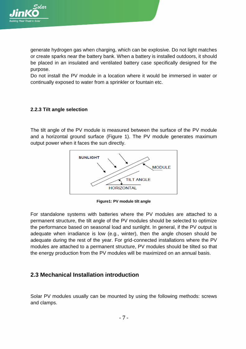
The tilt angle of the PV module is measured between the surface of the PV module
and a horizontal ground surface (Figure 1). The PV module generates maximum
output power when it faces the sun directly.
Figure1: PV module tilt angle
For standalone systems with batteries where the PV modules are attached to a
permanent structure, the tilt angle of the PV modules should be selected to optimize
the performance based on seasonal load and sunlight. In general, if the PV output is
adequate when irradiance is low (e.g., winter), then the angle chosen should be
adequate during the rest of the year. For grid-connected installations where the PV
modules are attached to a permanent structure, PV modules should be tilted so that
the energy production from the PV modules will be maximized on an annual basis.
2.3 Mechanical Installation introduction
Solar PV modules usually can be mounted by using the following methods: screws
and clamps.
- 8 -
﹡Note:
1) All installation methods herein are only for reference, and Jinko solar will not
provide related mounting components, the system installer or trained professional
personnel must be responsible for the PV system‟s design, installation, and
mechanical load calculation and security of the system.
2) Before installing, you should confirm below important things:
1) Visual check before installation, to make sure there is no bug in the packing
and junction box as well as the surface of module, If have , remove and clean
it .
2) Check the series number is right or not.
3) Jinko modules are designed to meet a maximum positive (or downward)
pressure of 5400Pa (Only refer to the mentioned module type in this manual) and
negative (or upward)pressure of 2400Pa. When mounting modules in
snow-prone or high-wind environments, Special care should be taken to mount
the modules in a manner that provides sufficient design strength while meeting
local code requirements.
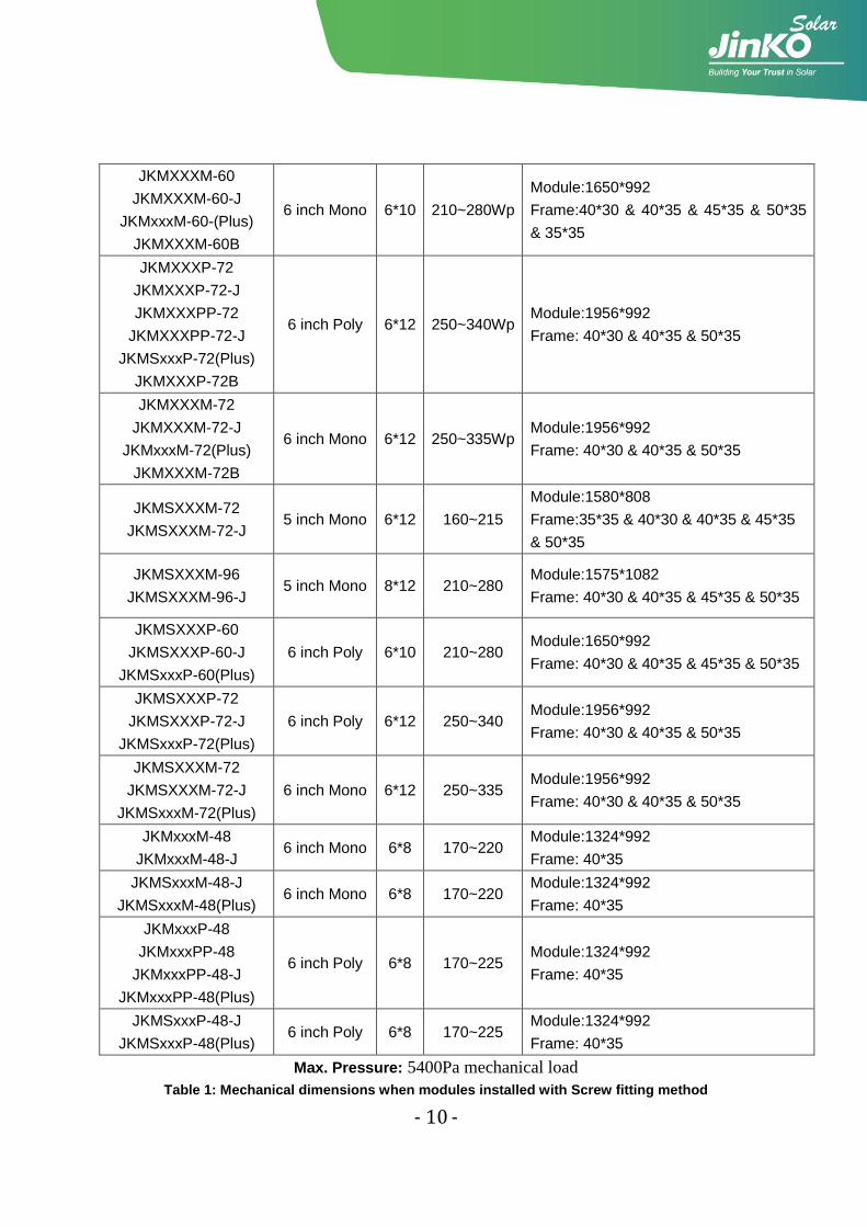
2.3.1 Fixation with screws
The applicable products please refer to table 1.
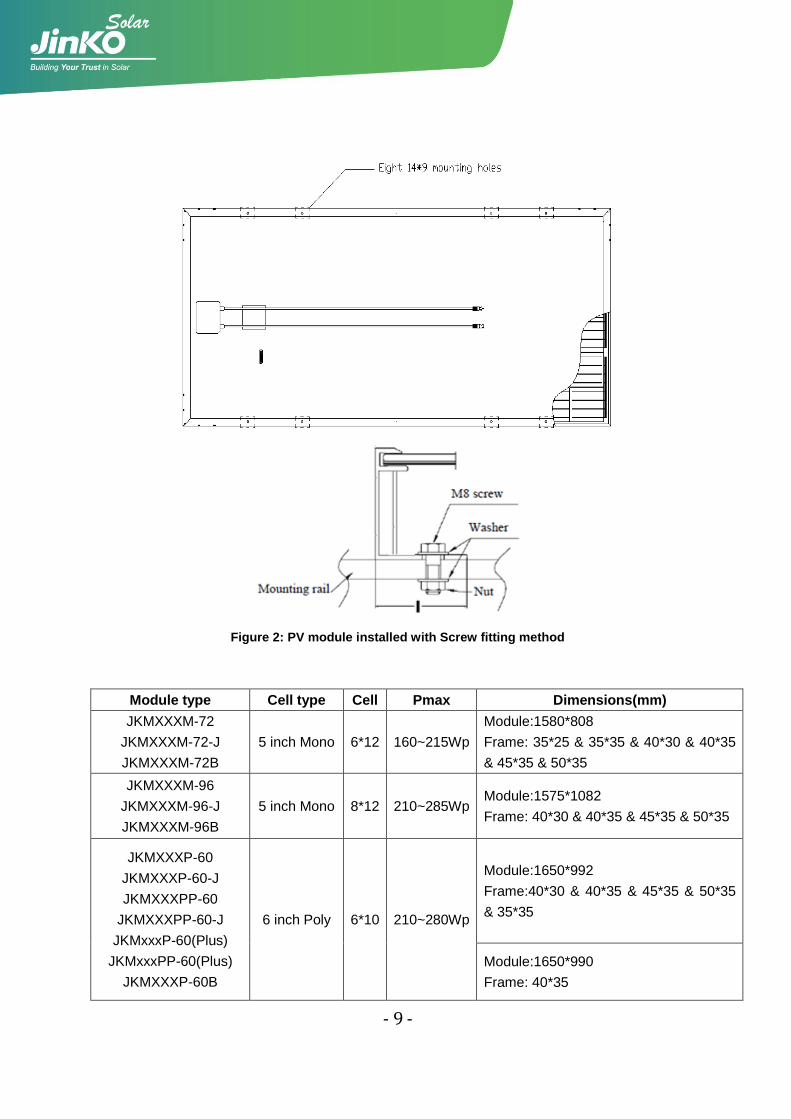
The frame of each module has 8 mounting holes (Length* Width: 14mm*9mm) used
to secure the modules to support structure. Always use all the eight mounting holes to
secure the modules. The module frame must be attached to a mounting rail using M8
corrosion-proof screws together with spring washers and flat washers in eight
symmetrical locations on the PV module. The applied torque value should be big
enough to fix the modules steadily. The reference value for M8 screw is 16~20N*m.
As to special support system or special installation requirement, please reconfirm
with the support‟s supplier for the torque value. Please find detailed mounting
information in the below illustration as Figure 2.
- 9 -
Figure 2: PV module installed with Screw fitting method
Module type Cell type Cell Pmax Dimensions(mm)
JKMXXXM-72
JKMXXXM-72-J
JKMXXXM-72B
5 inch Mono 6*12 160~215Wp
Module:1580*808
Frame: 35*25 & 35*35 & 40*30 & 40*35
& 45*35 & 50*35
JKMXXXM-96
JKMXXXM-96-J
JKMXXXM-96B
5 inch Mono 8*12 210~285Wp Module:1575*1082
Frame: 40*30 & 40*35 & 45*35 & 50*35
JKMXXXP-60
JKMXXXP-60-J
JKMXXXPP-60
JKMXXXPP-60-J
JKMxxxP-60(Plus)
JKMxxxPP-60(Plus)
JKMXXXP-60B
6 inch Poly 6*10 210~280Wp
Module:1650*992
Frame:40*30 & 40*35 & 45*35 & 50*35
& 35*35
Module:1650*990
Frame: 40*35
- 10 -
JKMXXXM-60
JKMXXXM-60-J
JKMxxxM-60-(Plus)
JKMXXXM-60B
6 inch Mono 6*10 210~280Wp
Module:1650*992
Frame:40*30 & 40*35 & 45*35 & 50*35
& 35*35
JKMXXXP-72
JKMXXXP-72-J
JKMXXXPP-72
JKMXXXPP-72-J
JKMSxxxP-72(Plus)
JKMXXXP-72B
6 inch Poly 6*12 250~340Wp Module:1956*992
Frame: 40*30 & 40*35 & 50*35
JKMXXXM-72
JKMXXXM-72-J
JKMxxxM-72(Plus)
JKMXXXM-72B
6 inch Mono 6*12 250~335Wp Module:1956*992
Frame: 40*30 & 40*35 & 50*35
JKMSXXXM-72
JKMSXXXM-72-J 5 inch Mono 6*12 160~215
Module:1580*808
Frame:35*35 & 40*30 & 40*35 & 45*35
& 50*35
JKMSXXXM-96
JKMSXXXM-96-J 5 inch Mono 8*12 210~280
Module:1575*1082
Frame: 40*30 & 40*35 & 45*35 & 50*35
JKMSXXXP-60
JKMSXXXP-60-J
JKMSxxxP-60(Plus)
6 inch Poly 6*10 210~280 Module:1650*992
Frame: 40*30 & 40*35 & 45*35 & 50*35
JKMSXXXP-72
JKMSXXXP-72-J
JKMSxxxP-72(Plus)
6 inch Poly 6*12 250~340 Module:1956*992
Frame: 40*30 & 40*35 & 50*35
JKMSXXXM-72
JKMSXXXM-72-J
JKMSxxxM-72(Plus)
6 inch Mono 6*12 250~335 Module:1956*992
Frame: 40*30 & 40*35 & 50*35
JKMxxxM-48
JKMxxxM-48-J 6 inch Mono 6*8 170~220
Module:1324*992
Frame: 40*35
JKMSxxxM-48-J
JKMSxxxM-48(Plus) 6 inch Mono 6*8 170~220
Module:1324*992
Frame: 40*35
JKMxxxP-48
JKMxxxPP-48
JKMxxxPP-48-J
JKMxxxPP-48(Plus)
6 inch Poly 6*8 170~225 Module:1324*992
Frame: 40*35
JKMSxxxP-48-J
JKMSxxxP-48(Plus) 6 inch Poly 6*8 170~225
Module:1324*992
Frame: 40*35
Max. Pressure: 5400Pa mechanical load
Table 1: Mechanical dimensions when modules installed with Screw fitting method
- 11 -
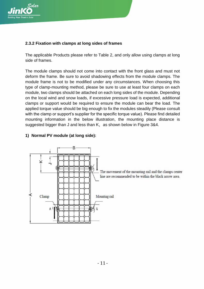
2.3.2 Fixation with clamps at long sides of frames
The applicable Products please refer to Table 2, and only allow using clamps at long
side of frames.
The module clamps should not come into contact with the front glass and must not
deform the frame. Be sure to avoid shadowing effects from the module clamps. The
module frame is not to be modified under any circumstances. When choosing this
type of clamp-mounting method, please be sure to use at least four clamps on each
module, two clamps should be attached on each long sides of the module. Depending
on the local wind and snow loads, if excessive pressure load is expected, additional
clamps or support would be required to ensure the module can bear the load. The
applied torque value should be big enough to fix the modules steadily (Please consult
with the clamp or support‟s supplier for the specific torque value). Please find detailed
mounting information in the below illustration, the mounting place distance is
suggested bigger than J and less than K,as shown below in Figure 3&4.
1) Normal PV module (at long side):
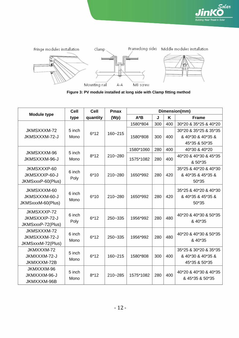
- 12 -
Figure 3: PV module installed at long side with Clamp fitting method
Module type Cell
type
Cell
quantity
Pmax
(Wp)
Dimension(mm)
A*B J K Frame
JKMSXXXM-72
JKMSXXXM-72-J
5 inch
Mono 6*12 160~215
1580*804 300 400 30*20 & 35*25 & 40*20
1580*808 300 400
30*20 & 35*25 & 35*35
& 40*30 & 40*35 &
45*35 & 50*35
JKMSXXXM-96
JKMSXXXM-96-J
5 inch
Mono 8*12 210~280
1580*1060 280 400 40*30 & 40*20
1575*1082 280 400 40*20 & 40*30 & 45*35
& 50*35
JKMSXXXP-60
JKMSXXXP-60-J
JKMSxxxP-60(Plus)
6 inch
Poly 6*10 210~280 1650*992 280 420
35*25 & 40*20 & 40*30
& 40*35 & 45*35 &
50*35
JKMSXXXM-60
JKMSXXXM-60-J
JKMSxxxM-60(Plus)
6 inch
Mono 6*10 210~280 1650*992 280 420
35*25 & 40*20 & 40*30
& 40*35 & 45*35 &
50*35
JKMSXXXP-72
JKMSXXXP-72-J
JKMSxxxP-72(Plus)
6 inch
Poly 6*12 250~335 1956*992 280 480
40*20 & 40*30 & 50*35
& 40*35
JKMSXXXM-72
JKMSXXXM-72-J
JKMSxxxM-72(Plus)
6 inch
Mono 6*12 250~335 1956*992 280 480
40*20 & 40*30 & 50*35
& 40*35
JKMXXXM-72
JKMXXXM-72-J
JKMXXXM-72B
5 inch
Mono 6*12 160~215 1580*808 300 400
35*25 & 30*20 & 35*35
& 40*30 & 40*35 &
45*35 & 50*35
JKMXXXM-96
JKMXXXM-96-J
JKMXXXM-96B
5 inch
Mono 8*12 210~285 1575*1082 280 400
40*20 & 40*30 & 40*35
& 45*35 & 50*35
- 13 -
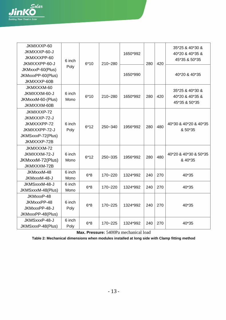
JKMXXXP-60
JKMXXXP-60-J
JKMXXXPP-60
JKMXXXPP-60-J
JKMxxxP-60(Plus)
JKMxxxPP-60(Plus)
JKMXXXP-60B
6 inch
Poly 6*10 210~280
1650*992
280 420
35*25 & 40*30 &
40*20 & 40*35 &
45*35 & 50*35
1650*990 40*20 & 40*35
JKMXXXM-60
JKMXXXM-60-J
JKMxxxM-60-(Plus)
JKMXXXM-60B
6 inch
Mono 6*10 210~280 1650*992 280 420
35*25 & 40*30 &
40*20 & 40*35 &
45*35 & 50*35
JKMXXXP-72
JKMXXXP-72-J
JKMXXXPP-72
JKMXXXPP-72-J
JKMSxxxP-72(Plus)
JKMXXXP-72B
6 inch
Poly 6*12 250~340 1956*992 280 480
40*30 & 40*20 & 40*35
& 50*35
JKMXXXM-72
JKMXXXM-72-J
JKMxxxM-72(Plus)
JKMXXXM-72B
6 inch
Mono 6*12 250~335 1956*992 280 480
40*20 & 40*30 & 50*35
& 40*35
JKMxxxM-48
JKMxxxM-48-J
6 inch
Mono 6*8 170~220 1324*992 240 270 40*35
JKMSxxxM-48-J
JKMSxxxM-48(Plus)
6 inch
Mono 6*8 170~220 1324*992 240 270 40*35
JKMxxxP-48
JKMxxxPP-48
JKMxxxPP-48-J
JKMxxxPP-48(Plus)
6 inch
Poly 6*8 170~225 1324*992 240 270 40*35
JKMSxxxP-48-J
JKMSxxxP-48(Plus)
6 inch
Poly 6*8 170~225 1324*992 240 270 40*35
Max. Pressure: 5400Pa mechanical load
Table 2: Mechanical dimensions when modules installed at long side with Clamp fitting method
- 14 -
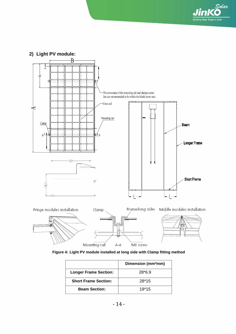
2) Light PV module:
Figure 4: Light PV module installed at long side with Clamp fitting method
Dimension (mm*mm)
Longer Frame Section: 28*6.9
Short Frame Section: 28*15
Beam Section: 19*15
- 15 -
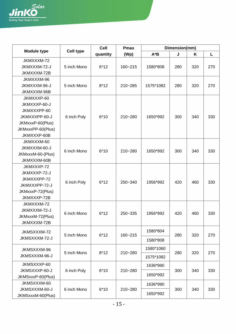
Module type Cell type Cell
quantity
Pmax
(Wp)
Dimension(mm)
A*B J K L
JKMXXXM-72
JKMXXXM-72-J
JKMXXXM-72B
5 inch Mono 6*12 160~215 1580*808 280 320 270
JKMXXXM-96
JKMXXXM-96-J
JKMXXXM-96B
5 inch Mono 8*12 210~285 1575*1082 280 320 270
JKMXXXP-60
JKMXXXP-60-J
JKMXXXPP-60
JKMXXXPP-60-J
JKMxxxP-60(Plus)
JKMxxxPP-60(Plus)
JKMXXXP-60B
6 inch Poly 6*10 210~280 1650*992 300 340 330
JKMXXXM-60
JKMXXXM-60-J
JKMxxxM-60-(Plus)
JKMXXXM-60B
6 inch Mono 6*10 210~280 1650*992 300 340 330
JKMXXXP-72
JKMXXXP-72-J
JKMXXXPP-72
JKMXXXPP-72-J
JKMxxxP-72(Plus)
JKMXXXP-72B
6 inch Poly 6*12 250~340 1956*992 420 460 330
JKMXXXM-72
JKMXXXM-72-J
JKMxxxM-72(Plus)
JKMXXXM-72B
6 inch Mono 6*12 250~335 1956*992 420 460 330
JKMSXXXM-72
JKMSXXXM-72-J 5 inch Mono 6*12 160~215
1580*804 280 320 270
1580*808
JKMSXXXM-96
JKMSXXXM-96-J 5 inch Mono 8*12 210~280
1580*1060 280 320 270
1575*1082
JKMSXXXP-60
JKMSXXXP-60-J
JKMSxxxP-60(Plus)
6 inch Poly 6*10 210~280
1636*990
300 340 330 1650*992
JKMSXXXM-60
JKMSXXXM-60-J
JKMSxxxM-60(Plus)
6 inch Mono 6*10 210~280
1636*990
300 340 330 1650*992
- 16 -
JKMSXXXP-72
JKMSXXXP-72-J
JKMSxxxP-72(Plus)
6 inch Poly 6*12 250~335
1952*990
420 460 330 1956*992
JKMSXXXM-72
JKMSXXXM-72-J
JKMSxxxM-72(Plus)
6 inch Mono 6*12 250~335 1952*990
420 460 330 1956*992
Max. Pressure: 2400Pa mechanical load
Table 3: Mechanical dimensions when modules installed at long side with Clamp fitting method
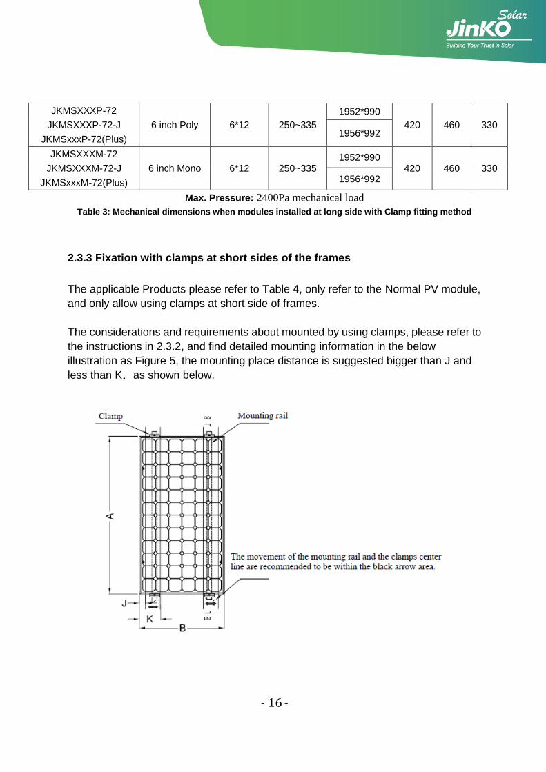
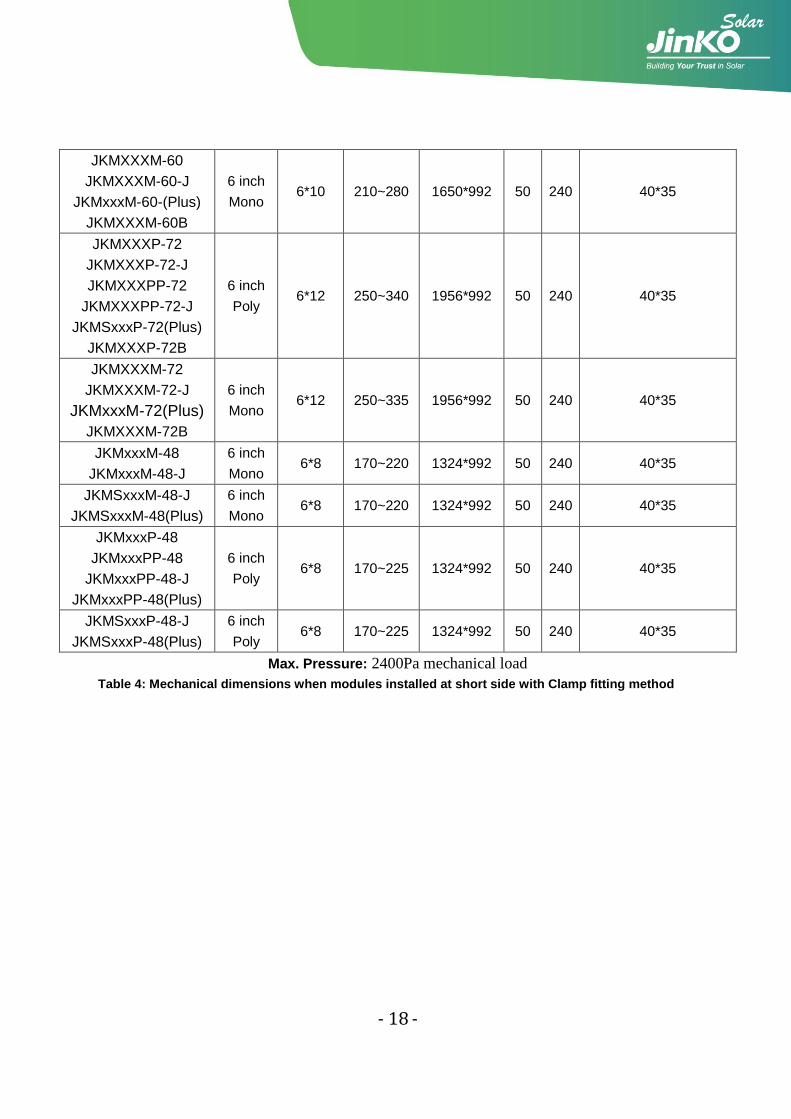
2.3.3 Fixation with clamps at short sides of the frames
The applicable Products please refer to Table 4, only refer to the Normal PV module,
and only allow using clamps at short side of frames.
The considerations and requirements about mounted by using clamps, please refer to
the instructions in 2.3.2, and find detailed mounting information in the below
illustration as Figure 5, the mounting place distance is suggested bigger than J and
less than K,as shown below.
- 17 -
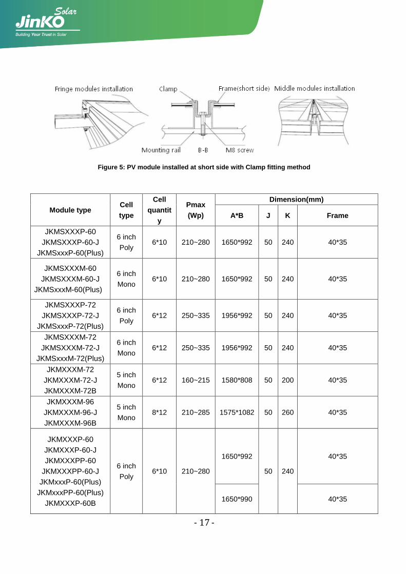
Figure 5: PV module installed at short side with Clamp fitting method
Module type Cell
type
Cell
quantit
y
Pmax
(Wp)
Dimension(mm)
A*B J K Frame
JKMSXXXP-60
JKMSXXXP-60-J
JKMSxxxP-60(Plus)
6 inch
Poly 6*10 210~280 1650*992 50 240 40*35
JKMSXXXM-60
JKMSXXXM-60-J
JKMSxxxM-60(Plus)
6 inch
Mono 6*10 210~280 1650*992 50 240 40*35
JKMSXXXP-72
JKMSXXXP-72-J
JKMSxxxP-72(Plus)
6 inch
Poly 6*12 250~335 1956*992 50 240 40*35
JKMSXXXM-72
JKMSXXXM-72-J
JKMSxxxM-72(Plus)
6 inch
Mono 6*12 250~335 1956*992 50 240 40*35
JKMXXXM-72
JKMXXXM-72-J
JKMXXXM-72B
5 inch
Mono 6*12 160~215 1580*808 50 200 40*35
JKMXXXM-96
JKMXXXM-96-J
JKMXXXM-96B
5 inch
Mono 8*12 210~285 1575*1082 50 260 40*35
JKMXXXP-60
JKMXXXP-60-J
JKMXXXPP-60
JKMXXXPP-60-J
JKMxxxP-60(Plus)
JKMxxxPP-60(Plus)
JKMXXXP-60B
6 inch
Poly 6*10 210~280
1650*992
50 240
40*35
1650*990 40*35
- 18 -
JKMXXXM-60
JKMXXXM-60-J
JKMxxxM-60-(Plus)
JKMXXXM-60B
6 inch
Mono 6*10 210~280 1650*992 50 240 40*35
JKMXXXP-72
JKMXXXP-72-J
JKMXXXPP-72
JKMXXXPP-72-J
JKMSxxxP-72(Plus)
JKMXXXP-72B
6 inch
Poly 6*12 250~340 1956*992 50 240 40*35
JKMXXXM-72
JKMXXXM-72-J
JKMxxxM-72(Plus)
JKMXXXM-72B
6 inch
Mono 6*12 250~335 1956*992 50 240 40*35
JKMxxxM-48
JKMxxxM-48-J
6 inch
Mono 6*8 170~220 1324*992 50 240 40*35
JKMSxxxM-48-J
JKMSxxxM-48(Plus)
6 inch
Mono 6*8 170~220 1324*992 50 240 40*35
JKMxxxP-48
JKMxxxPP-48
JKMxxxPP-48-J
JKMxxxPP-48(Plus)
6 inch
Poly 6*8 170~225 1324*992 50 240 40*35
JKMSxxxP-48-J
JKMSxxxP-48(Plus)
6 inch
Poly 6*8 170~225 1324*992 50 240 40*35
Max. Pressure: 2400Pa mechanical load
Table 4: Mechanical dimensions when modules installed at short side with Clamp fitting method
- 19 -
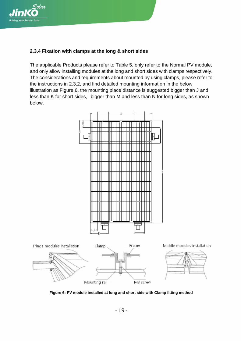
2.3.4 Fixation with clamps at the long & short sides
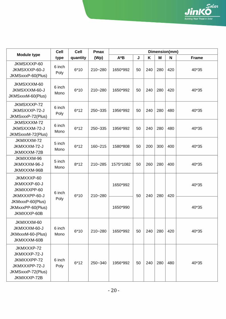
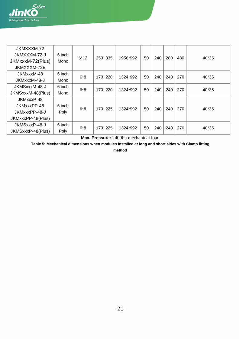
The applicable Products please refer to Table 5, only refer to the Normal PV module,
and only allow installing modules at the long and short sides with clamps respectively.
The considerations and requirements about mounted by using clamps, please refer to
the instructions in 2.3.2, and find detailed mounting information in the below
illustration as Figure 6, the mounting place distance is suggested bigger than J and
less than K for short sides,bigger than M and less than N for long sides, as shown
below.
Figure 6: PV module installed at long and short side with Clamp fitting method
- 20 -
Module type Cell
type
Cell
quantity
Pmax
(Wp)
Dimension(mm)
A*B J K M N Frame
JKMSXXXP-60
JKMSXXXP-60-J
JKMSxxxP-60(Plus)
6 inch
Poly 6*10 210~280 1650*992 50 240 280 420 40*35
JKMSXXXM-60
JKMSXXXM-60-J
JKMSxxxM-60(Plus)
6 inch
Mono 6*10 210~280 1650*992 50 240 280 420 40*35
JKMSXXXP-72
JKMSXXXP-72-J
JKMSxxxP-72(Plus)
6 inch
Poly 6*12 250~335 1956*992 50 240 280 480 40*35
JKMSXXXM-72
JKMSXXXM-72-J
JKMSxxxM-72(Plus)
6 inch
Mono 6*12 250~335 1956*992 50 240 280 480 40*35
JKMXXXM-72
JKMXXXM-72-J
JKMXXXM-72B
5 inch
Mono 6*12 160~215 1580*808 50 200 300 400 40*35
JKMXXXM-96
JKMXXXM-96-J
JKMXXXM-96B
5 inch
Mono 8*12 210~285 1575*1082 50 260 280 400 40*35
JKMXXXP-60
JKMXXXP-60-J
JKMXXXPP-60
JKMXXXPP-60-J
JKMxxxP-60(Plus)
JKMxxxPP-60(Plus)
JKMXXXP-60B
6 inch
Poly 6*10 210~280
1650*992
50 240 280 420
40*35
1650*990 40*35
JKMXXXM-60
JKMXXXM-60-J
JKMxxxM-60-(Plus)
JKMXXXM-60B
6 inch
Mono 6*10 210~280 1650*992 50 240 280 420 40*35
JKMXXXP-72
JKMXXXP-72-J
JKMXXXPP-72
JKMXXXPP-72-J
JKMSxxxP-72(Plus)
JKMXXXP-72B
6 inch
Poly 6*12 250~340 1956*992 50 240 280 480 40*35
- 21 -
JKMXXXM-72
JKMXXXM-72-J
JKMxxxM-72(Plus)
JKMXXXM-72B
6 inch
Mono 6*12 250~335 1956*992 50 240 280 480 40*35
JKMxxxM-48
JKMxxxM-48-J
6 inch
Mono 6*8 170~220 1324*992 50 240 240 270 40*35
JKMSxxxM-48-J
JKMSxxxM-48(Plus)
6 inch
Mono 6*8 170~220 1324*992 50 240 240 270 40*35
JKMxxxP-48
JKMxxxPP-48
JKMxxxPP-48-J
JKMxxxPP-48(Plus)
6 inch
Poly 6*8 170~225 1324*992 50 240 240 270 40*35
JKMSxxxP-48-J
JKMSxxxP-48(Plus)
6 inch
Poly 6*8 170~225 1324*992 50 240 240 270 40*35
Max. Pressure: 2400Pa mechanical load
Table 5: Mechanical dimensions when modules installed at long and short sides with Clamp fitting
method
- 22 -
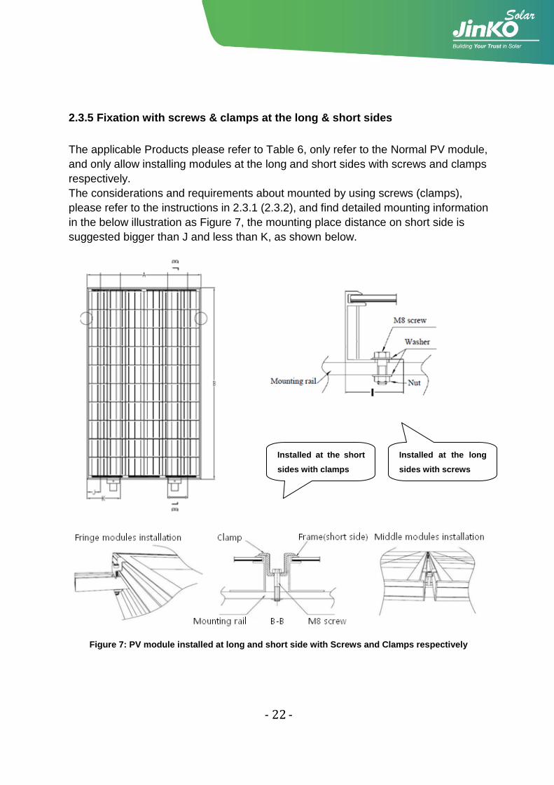
2.3.5 Fixation with screws & clamps at the long & short sides
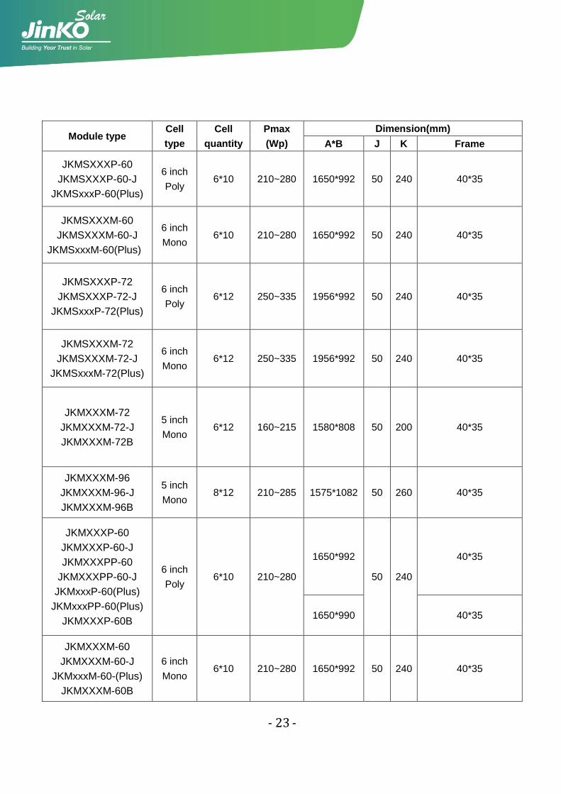
The applicable Products please refer to Table 6, only refer to the Normal PV module,
and only allow installing modules at the long and short sides with screws and clamps
respectively.
The considerations and requirements about mounted by using screws (clamps),
please refer to the instructions in 2.3.1 (2.3.2), and find detailed mounting information
in the below illustration as Figure 7, the mounting place distance on short side is
suggested bigger than J and less than K, as shown below.
Figure 7: PV module installed at long and short side with Screws and Clamps respectively
Installed at the long
sides with screws
Installed at the short
sides with clamps
- 23 -
Module type Cell
type
Cell
quantity
Pmax
(Wp)
Dimension(mm)
A*B J K Frame
JKMSXXXP-60
JKMSXXXP-60-J
JKMSxxxP-60(Plus)
6 inch
Poly 6*10 210~280 1650*992 50 240 40*35
JKMSXXXM-60
JKMSXXXM-60-J
JKMSxxxM-60(Plus)
6 inch
Mono 6*10 210~280 1650*992 50 240 40*35
JKMSXXXP-72
JKMSXXXP-72-J
JKMSxxxP-72(Plus)
6 inch
Poly 6*12 250~335 1956*992 50 240 40*35
JKMSXXXM-72
JKMSXXXM-72-J
JKMSxxxM-72(Plus)
6 inch
Mono 6*12 250~335 1956*992 50 240 40*35
JKMXXXM-72
JKMXXXM-72-J
JKMXXXM-72B
5 inch
Mono 6*12 160~215 1580*808 50 200 40*35
JKMXXXM-96
JKMXXXM-96-J
JKMXXXM-96B
5 inch
Mono 8*12 210~285 1575*1082 50 260 40*35
JKMXXXP-60
JKMXXXP-60-J
JKMXXXPP-60
JKMXXXPP-60-J
JKMxxxP-60(Plus)
JKMxxxPP-60(Plus)
JKMXXXP-60B
6 inch
Poly 6*10 210~280
1650*992
50 240
40*35
1650*990 40*35
JKMXXXM-60
JKMXXXM-60-J
JKMxxxM-60-(Plus)
JKMXXXM-60B
6 inch
Mono 6*10 210~280 1650*992 50 240 40*35
- 24 -
JKMXXXP-72
JKMXXXP-72-J
JKMXXXPP-72
JKMXXXPP-72-J
JKMSxxxP-72(Plus)
JKMXXXP-72B
6 inch
Poly 6*12 250~340 1956*992 50 240 40*35
JKMXXXM-72
JKMXXXM-72-J
JKMxxxM-72(Plus)
JKMXXXM-72B
6 inch
Mono 6*12 250~335 1956*992 50 240 40*35
JKMxxxM-48
JKMxxxM-48-J
6 inch
Mono 6*8 170~220 1324*992 50 240 40*35
JKMSxxxM-48-J
JKMSxxxM-48(Plus)
6 inch
Mono 6*8 170~220 1324*992 50 240 40*35
JKMxxxP-48
JKMxxxPP-48
JKMxxxPP-48-J
JKMxxxPP-48(Plus)
6 inch
Poly 6*8 170~225 1324*992 50 240 40*35
JKMSxxxP-48-J
JKMSxxxP-48(Plus)
6 inch
Poly 6*8 170~225 1324*992 50 240 40*35
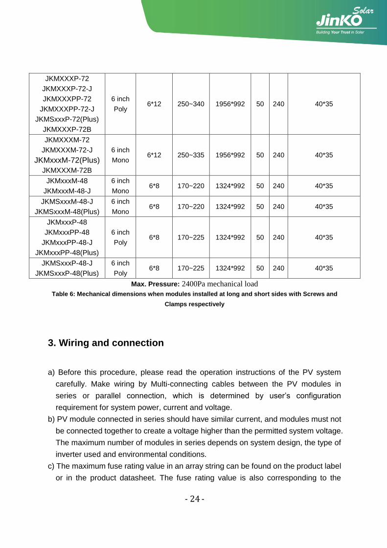
Max. Pressure: 2400Pa mechanical load
Table 6: Mechanical dimensions when modules installed at long and short sides with Screws and
Clamps respectively
3. Wiring and connection
a) Before this procedure, please read the operation instructions of the PV system
carefully. Make wiring by Multi-connecting cables between the PV modules in
series or parallel connection, which is determined by user‟s configuration
requirement for system power, current and voltage.
b) PV module connected in series should have similar current, and modules must not
be connected together to create a voltage higher than the permitted system voltage.
The maximum number of modules in series depends on system design, the type of
inverter used and environmental conditions.
c) The maximum fuse rating value in an array string can be found on the product label
or in the product datasheet. The fuse rating value is also corresponding to the
- 25 -
maximum reverse current that a module can withstand, i.e. when one string is in
shade then the other parallel strings of modules will be load by the shade string and
the current will pass through to create a current circuit. Thus based on the
maximum series fuse rating of module and local electrical installation criteria, make
sure the modules strings in parallel for connection need to be assembled with
appropriate string fuse for circuit protection.
d) Open the connection box of the control system and connect the cabled from the PV
arrays to the connection box in accordance with the installation indication of the PV
control systems. The cross-sectional area and cable connector capacity must
satisfy the maximum short-circuit of PV system (For a single component, we
recommended the cross-sectional area of cables is 4mm2 and the rated current of
connectors is more than 10A), otherwise cables and connectors will become
overheating for large current. Please pay attention the temperature limit of cables is
85℃.
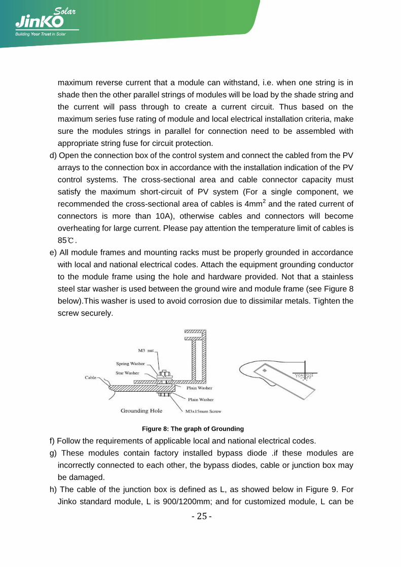
e) All module frames and mounting racks must be properly grounded in accordance
with local and national electrical codes. Attach the equipment grounding conductor
to the module frame using the hole and hardware provided. Not that a stainless
steel star washer is used between the ground wire and module frame (see Figure 8
below).This washer is used to avoid corrosion due to dissimilar metals. Tighten the
screw securely.
Figure 8: The graph of Grounding
f) Follow the requirements of applicable local and national electrical codes.
g) These modules contain factory installed bypass diode .if these modules are
incorrectly connected to each other, the bypass diodes, cable or junction box may
be damaged.
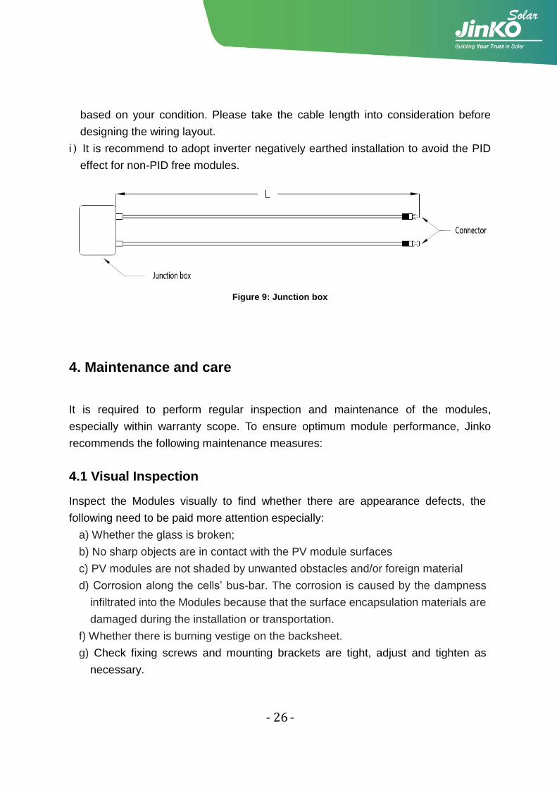
h) The cable of the junction box is defined as L, as showed below in Figure 9. For
Jinko standard module, L is 900/1200mm; and for customized module, L can be
- 26 -
based on your condition. Please take the cable length into consideration before
designing the wiring layout.
i)It is recommend to adopt inverter negatively earthed installation to avoid the PID
effect for non-PID free modules.
Figure 9: Junction box
4. Maintenance and care
It is required to perform regular inspection and maintenance of the modules,
especially within warranty scope. To ensure optimum module performance, Jinko
recommends the following maintenance measures:
4.1 Visual Inspection
Inspect the Modules visually to find whether there are appearance defects, the
following need to be paid more attention especially:
a) Whether the glass is broken;
b) No sharp objects are in contact with the PV module surfaces
c) PV modules are not shaded by unwanted obstacles and/or foreign material
d) Corrosion along the cells‟ bus-bar. The corrosion is caused by the dampness
infiltrated into the Modules because that the surface encapsulation materials are
damaged during the installation or transportation.
f) Whether there is burning vestige on the backsheet.
g) Check fixing screws and mounting brackets are tight, adjust and tighten as
necessary.
- 27 -
4.2 Cleaning
a) A built up of dust or dirt on the module(s) front face will result in a decreased
energy output. Clean the panel(s) preferably once per annum if possible
(depend on site conditions) using a soft cloth dry or damp, as necessary. Water
with high mineral content may leave deposits on the glass surface and is not
recommended.
b) Never use abrasive material under any circumstances.
c) In order to reduce the potential for electrical and thermal shock, Jinko
recommends cleaning PV modules during early morning or late afternoon hours
when solar radiation is low and the modules are cooler, especially in regions
with hotter temperatures.
d) Never attempt to clean a PV module with broken glass or other signs of
exposed wiring, as this presents a shock hazard.
4.3 Inspection of Connector and Cable
It‟s recommended to implement the following preventive maintenance every 6
months:
a) Check the sealing gels of the junction box to ensure it have no crack or crevice.
b) Examine the PV module(s) for signs of deterioration. Check all wiring for
possible rodent damage, weathering and that all connections are tight and
corrosion free. Check electrical leakage to ground.
5. Electrical specification
The module electrical rating are measured under Standard Test Conditions, which
are 1000W/m2, irradiance with AM 1.5 spectrum and 25 deg (77°F) ambient
temperature. The module might produce more or less voltage or current than rating
value in uncertainty condition.
The corresponding electrical specification can be downloaded from website
www.jinkosolar.com.
- 28 -
6. Disclaimer of Liability
Because the use of the manual and the conditions or methods of installation,
operation, use and maintenance of photovoltaic (PV) product are beyond
Jinko‟s control, Jinko does not accept responsibility and expressly disclaims
liability for loss ,damage, or expense arising out of or in any way connected
with such installation, operation, use or maintenance.
No responsibility is assumed by Jinko for any infringement of patents or other
rights of third parties, which may result from use of the PV product. NO license
is granted by implication or otherwise under any patent or patent rights.
The information in this manual is based on Jinko‟s knowledge and experience
and is believed to be reliable, but such information including product
specification (without limitations) and suggestions do not constitute a warranty,
expresses or implied. Jinko reserve the right to change the manual, the PV
produce, the specifications, or product information sheets without prior notice.
Note

16F, Building No.2428# South Yang Gao Road,Shanghai, China 200127Tel: +86 21 6061 1799Fax: +86 21 6876 1115
www.jinkosolar.com | Technic Support: [email protected] | After-sales: [email protected]
Global Sales & Marketing CenterNo.1 Jinko Road,Shangrao Economic Development Zone, Jiangxi Province, China 334100Tel:+86 793 858 8188 Fax:+86 793 846 1152
Jiangxi Manufacture BaseNo.58 Yuanxi Road, Haining Yuanhua Industrial Park, Zhejiang Province, China 314416Tel: +86 573 8798 5678Fax: +86 573 8787 1070
Zhejiang Manufacture Base