Embed Size (px)
Citation preview

Philips CMS Patient Monitoring System
Service Guide
PAD Part No. M1046-9423LPrinted September 2002
Notice
This document contains proprietary information which is protected by copyright. All Rights Reserved. Reproduction, adaptation, or translation without prior written permission is prohibited, except as allowed under the copyright laws.
Philips Medical SystemsCardiac and Monitoring Systems3000 Minuteman RoadAndover, MA 01810+1 (800) 934-7372
Publication numberM1046-9423LPrinted in Germany
Warranty The information contained in this document is subject to change without notice.
Philips makes no warranty of any kind with regard to this material, including, but not limited to, the implied warranties or merchantability and fitness for a particular purpose.
Philips shall not be liable for errors contained herein or for incidental or consequential damages in connection with the furnishing, performance, or use of this material.
© 2002 Philips Medizin Systeme Böblingen GmbHAll rights are reserved.Reproduction in whole or in part is prohibited without the prior written consent of thecopyright holder.
ii
Printing History
New editions of this document will incorporate all material updated since the previous edition. Update packages may be issued between editions and contain replacement and additional pages to be merged by a revision date at the bottom of the page. Note that pages which are rearranged due to changes on a previous page are not considered revised.
The documentation printing date and part number indicate its current edition. The printing date and part number change when a new edition is printed.
Part Number M1046-9303F First Edition ......................................... January 1996
Part Number M1046-9303G Second Edition .....................................May 1997
Part Number M1046-9088G Third Edition........................................ January 1998
Part Number M1046-9303H Fourth Edition ...................................... June 1998
Part Number M1046-9303KFifth Edition .........................................March 1999
Part Number M1046-9303LSixth Edition ........................................ June 2000
Part Number M1046-9423LSeventh Edition.................................... September 2002
iii

Overview
Introduction The Philips CMS Patient Monitoring System Service Guide is a reference guide featuring six chapters on how to test, troubleshoot, and repair the instrument.
The Philips CMS Patient Monitoring System and the Philips Anesthesia CMS Patient Monitoring System, as well as the Philips Neonatal CMS Patient Monitoring System will be referred to throughout this guide as the CMS.
Target Audience This reference guide is intended for hospital Biomedical Engineers and Technicians, Philips Customer Engineers, Response Center Engineers, and Installation Planning Specialists who have experience servicing Philips patient monitoring devices or similar products.
Prerequisites In addition to this guide we recommend you to complete the Philips Patient Monitors – Concepts Guide also contained in the Service Training Kit.
Course Objectives This guides objectives are:
• Identify the major units of CMS.
• Identify the controls and connectors of the major units of CMS.
• Identify the four operating modes of CMS.
• Connect the cabling of the CMS.
• Complete a Quick Check of the system.
• Perform Safety checks.
• Perform recommended maintenance.
• Perform a general inspection of the system.
• Clean the major units of the CMS.
• Perform Self-check procedures for CMS modules.
• Recognize a properly operating CMS.
• Identify symptoms of improper operation for the CMS.
• Use any symptoms or indications to identify a fault as being in the display module, computer module, or the plug-in parameter modules.
• Further isolate faults down to field-replaceable assemblies.
• Locate and understand the removal and replacement procedures for the CMS and ACMS.
• Provide a list of available parts for the CMS and ACMS.
iv
In This Guide
Chapter 1 - Introducing the CMS provides a physical/functional overview of the monitor.
Chapter 2 - Testing & Maintaining the CMS describes how to test, maintain and check that the instrument operates in an optimum condition.
Chapter 3 - Troubleshooting the CMS provides troubleshooting and diagnostic procedures for the monitor.
Chapter 4 - Troubleshooting the Plug-in Modules provides troubleshooting and self-test procedures for the parameter modules.
Chapter 5 - Repairing the CMS includes removal and replacement procedures for field replaceable parts.
Chapter 6 - Parts List for CMS lists replacement and exchange part numbers for the instrument.
Appendix A - Product Information gives a listing of the options for the monitor.
Appendix B - Conversion Charts gives relative conversion information.
Appendix C - Philips 15210B Calibration Unit gives service and installation information for this instrument used in calibrating plug-in modules.
Appendix D - CPC Programming Tool Manual
Glossary gives relevant definitions for the system
Index gives an alphabetical listing the contents of the guide.
v

How to Use this Guide
Each chapter begins with a title which is followed by three sections: an opening statement, an objectives statement and a concepts listing. These three sections can be thought of as your guide to the chapter. They will tell you what you are going to find in the chapter, what you should take away from the chapter in the way of goals and terms, and concepts central to the chapter.
Chapters containing procedures will then proceed with a procedure overview table and the body of the chapter. The procedure overview table is your guide to the actual procedures in the chapter. It is designed to be used by an experienced user who needs a quick review of the procedure or a page number of a particular procedure.
The body of the chapter will cover all of the procedures associated with the task. In order to make the procedure easier to follow, we have kept the body of the text focused on the procedure at hand and pulled the extra information, which might be helpful to a new engineer, into the outside column. Here is a formatting example:
___________________________________________________________________
Example: Inspect the System Hardware
No tools are required to perform this inspection.
Step 1 Examine the exterior of the unit for cleanliness and general physical condition. Check that the plastic housings are intact, that all hardware is present and tight, and that there are no signs of spilled liquids or other serious abuse.
Step 2 Check fuse values and type against that marked on the chassis, and ensure that a spare is provided.
Step 3 Inspect connectors of the module rack and ensure that the plug-in modules are locked into place and do not slide out without first releasing the locking plate on the bottom of the module.
Step 4 Ensure all labeling is present and legible.
Step 5 Inspect all accessories external to the system such as transducers, referring to the manufacturer’s documentation.
___________________________________________________________________
Inspecting the system on an annual basis will help you keep track of your system and identify potential parts that need to be replaced.
vi

vii

viii

Table of Contents
1. Introducing the CMS . . . . . . . . . . . . . . . . . . . . . . . . . . . . . . . . . . . . . . . . . . . . . . . . . . . . . . . .1-1Objectives . . . . . . . . . . . . . . . . . . . . . . . . . . . . . . . . . . . . . . . . . . . . . . . . . . . . . . . . . . . . . . . . . . . . . . . . . . . . . . . . 1-1Concepts . . . . . . . . . . . . . . . . . . . . . . . . . . . . . . . . . . . . . . . . . . . . . . . . . . . . . . . . . . . . . . . . . . . . . . . . . . . . . . . . . 1-2Main Display Module . . . . . . . . . . . . . . . . . . . . . . . . . . . . . . . . . . . . . . . . . . . . . . . . . . . . . . . . . . . . . . . . . . . . . . . 1-4
Objective . . . . . . . . . . . . . . . . . . . . . . . . . . . . . . . . . . . . . . . . . . . . . . . . . . . . . . . . . . . . . . . . . . . . . . . . . . . . . 1-4Concepts . . . . . . . . . . . . . . . . . . . . . . . . . . . . . . . . . . . . . . . . . . . . . . . . . . . . . . . . . . . . . . . . . . . . . . . . . . . . . 1-4Front Panel Controls and Connectors – CRT Display. . . . . . . . . . . . . . . . . . . . . . . . . . . . . . . . . . . . . . . . . . . 1-7Front Panel Controls and Connectors – Flatscreen Display . . . . . . . . . . . . . . . . . . . . . . . . . . . . . . . . . . . . . . 1-8Rear Panel Controls and Connectors . . . . . . . . . . . . . . . . . . . . . . . . . . . . . . . . . . . . . . . . . . . . . . . . . . . . . . . 1-11
Slave Display Module. . . . . . . . . . . . . . . . . . . . . . . . . . . . . . . . . . . . . . . . . . . . . . . . . . . . . . . . . . . . . . . . . . . . . . 1-1314" Slave Display Front Panel Controls . . . . . . . . . . . . . . . . . . . . . . . . . . . . . . . . . . . . . . . . . . . . . . . . . . . . 1-1414" Slave Display Rear Panel Controls and Connectors . . . . . . . . . . . . . . . . . . . . . . . . . . . . . . . . . . . . . . . . 1-14
Handheld Keypad . . . . . . . . . . . . . . . . . . . . . . . . . . . . . . . . . . . . . . . . . . . . . . . . . . . . . . . . . . . . . . . . . . . . . . . . .1-16Objective . . . . . . . . . . . . . . . . . . . . . . . . . . . . . . . . . . . . . . . . . . . . . . . . . . . . . . . . . . . . . . . . . . . . . . . . . . . . 1-16Concepts . . . . . . . . . . . . . . . . . . . . . . . . . . . . . . . . . . . . . . . . . . . . . . . . . . . . . . . . . . . . . . . . . . . . . . . . . . . . 1-16Handheld Keypad Membrane Keyboard . . . . . . . . . . . . . . . . . . . . . . . . . . . . . . . . . . . . . . . . . . . . . . . . . . . . 1-17Handheld Keypad Rear Cover . . . . . . . . . . . . . . . . . . . . . . . . . . . . . . . . . . . . . . . . . . . . . . . . . . . . . . . . . . . .1-18External Alarm Device M1109A. . . . . . . . . . . . . . . . . . . . . . . . . . . . . . . . . . . . . . . . . . . . . . . . . . . . . . . . . . 1-18
Computer Module . . . . . . . . . . . . . . . . . . . . . . . . . . . . . . . . . . . . . . . . . . . . . . . . . . . . . . . . . . . . . . . . . . . . . . . . .1-19Objective . . . . . . . . . . . . . . . . . . . . . . . . . . . . . . . . . . . . . . . . . . . . . . . . . . . . . . . . . . . . . . . . . . . . . . . . . . . . 1-19Concepts . . . . . . . . . . . . . . . . . . . . . . . . . . . . . . . . . . . . . . . . . . . . . . . . . . . . . . . . . . . . . . . . . . . . . . . . . . . . 1-19Brief Functional Overview . . . . . . . . . . . . . . . . . . . . . . . . . . . . . . . . . . . . . . . . . . . . . . . . . . . . . . . . . . . . . . 1-20Delivered Configurations. . . . . . . . . . . . . . . . . . . . . . . . . . . . . . . . . . . . . . . . . . . . . . . . . . . . . . . . . . . . . . . . 1-21Function Cards of the Computer Module . . . . . . . . . . . . . . . . . . . . . . . . . . . . . . . . . . . . . . . . . . . . . . . . . . .1-21Function Card Placement. . . . . . . . . . . . . . . . . . . . . . . . . . . . . . . . . . . . . . . . . . . . . . . . . . . . . . . . . . . . . . . . 1-22EEPROM Numbers . . . . . . . . . . . . . . . . . . . . . . . . . . . . . . . . . . . . . . . . . . . . . . . . . . . . . . . . . . . . . . . . . . . . 1-28Front Connectors . . . . . . . . . . . . . . . . . . . . . . . . . . . . . . . . . . . . . . . . . . . . . . . . . . . . . . . . . . . . . . . . . . . . . . 1-33Rear Connectors. . . . . . . . . . . . . . . . . . . . . . . . . . . . . . . . . . . . . . . . . . . . . . . . . . . . . . . . . . . . . . . . . . . . . . . 1-35Computer Module External Connector Pinouts. . . . . . . . . . . . . . . . . . . . . . . . . . . . . . . . . . . . . . . . . . . . . . . 1-36
Mounting the CMS . . . . . . . . . . . . . . . . . . . . . . . . . . . . . . . . . . . . . . . . . . . . . . . . . . . . . . . . . . . . . . . . . . . . . . . . 1-39Connecting the CMS Cables. . . . . . . . . . . . . . . . . . . . . . . . . . . . . . . . . . . . . . . . . . . . . . . . . . . . . . . . . . . . . . . . . 1-39
To Connect the Computer Module and Plug-in Module Rack . . . . . . . . . . . . . . . . . . . . . . . . . . . . . . . . . . . 1-39To Connect the CRT Display to the Computer Module . . . . . . . . . . . . . . . . . . . . . . . . . . . . . . . . . . . . . . . . 1-41To Connect the Flatscreen Display to the Computer Module . . . . . . . . . . . . . . . . . . . . . . . . . . . . . . . . . 1-42To Connect the XGA-Compatible Display to the Computer Module . . . . . . . . . . . . . . . . . . . . . . . . . . . . . . 1-42To Connect the Satellite Rack . . . . . . . . . . . . . . . . . . . . . . . . . . . . . . . . . . . . . . . . . . . . . . . . . . . . . . . . . . . .1-42To Connect the Strip Recorder . . . . . . . . . . . . . . . . . . . . . . . . . . . . . . . . . . . . . . . . . . . . . . . . . . . . . . . . . . . 1-42To Connect the Handheld Keypad to the CRT Display Module . . . . . . . . . . . . . . . . . . . . . . . . . . . . . . . . . . 1-42To Connect the Handheld Keypad to the External Alarm Device . . . . . . . . . . . . . . . . . . . . . . . . . . . . . . . . 1-43To Connect the External Alarm Device to the Computer Module . . . . . . . . . . . . . . . . . . . . . . . . . . . . . . . . 1-43To Connect Printers and PCs. . . . . . . . . . . . . . . . . . . . . . . . . . . . . . . . . . . . . . . . . . . . . . . . . . . . . . . . . . . . . 1-43
Configuring and Adjusting Displays . . . . . . . . . . . . . . . . . . . . . . . . . . . . . . . . . . . . . . . . . . . . . . . . . . . . . . . . . . 1-45Introduction . . . . . . . . . . . . . . . . . . . . . . . . . . . . . . . . . . . . . . . . . . . . . . . . . . . . . . . . . . . . . . . . . . . . . . . . . . 1-45Configuring the RS-232 Port . . . . . . . . . . . . . . . . . . . . . . . . . . . . . . . . . . . . . . . . . . . . . . . . . . . . . . . . . . . . . 1-45XGA Display Adjustments . . . . . . . . . . . . . . . . . . . . . . . . . . . . . . . . . . . . . . . . . . . . . . . . . . . . . . . . . . . . . . 1-46Calibrating the Touch Screen . . . . . . . . . . . . . . . . . . . . . . . . . . . . . . . . . . . . . . . . . . . . . . . . . . . . . . . . . . . . 1-47Performing the Functionality Test . . . . . . . . . . . . . . . . . . . . . . . . . . . . . . . . . . . . . . . . . . . . . . . . . . . . . . . . .1-48
Configuring the Mouse or Trackball . . . . . . . . . . . . . . . . . . . . . . . . . . . . . . . . . . . . . . . . . . . . . . . . . . . . . . . . . . 1-49Introduction . . . . . . . . . . . . . . . . . . . . . . . . . . . . . . . . . . . . . . . . . . . . . . . . . . . . . . . . . . . . . . . . . . . . . . . . . . 1-49Configuring the RS-232 Port . . . . . . . . . . . . . . . . . . . . . . . . . . . . . . . . . . . . . . . . . . . . . . . . . . . . . . . . . . . . . 1-49Performing the Functionality Test . . . . . . . . . . . . . . . . . . . . . . . . . . . . . . . . . . . . . . . . . . . . . . . . . . . . . . . . .1-49
Contents-ix

Adjusting the Pointer Speed of the Mouse or Trackball (Optional) . . . . . . . . . . . . . . . . . . . . . . . . . . . . . . . 1-50Integral Power Supply - Computer Module (M1046B) . . . . . . . . . . . . . . . . . . . . . . . . . . . . . . . . . . . . . . . . . . . . 1-51
Integral Power Supply - Connectors and Controls . . . . . . . . . . . . . . . . . . . . . . . . . . . . . . . . . . . . . . . . . . . . 1-51Remote Power Supply . . . . . . . . . . . . . . . . . . . . . . . . . . . . . . . . . . . . . . . . . . . . . . . . . . . . . . . . . . . . . . . . . . . . . 1-52
Front Panel Controls - Remote Power Supply . . . . . . . . . . . . . . . . . . . . . . . . . . . . . . . . . . . . . . . . . . . . . . . 1-52Remote Power Supply - Rear Controls and Connectors. . . . . . . . . . . . . . . . . . . . . . . . . . . . . . . . . . . . . . . . 1-53
Fuse Values . . . . . . . . . . . . . . . . . . . . . . . . . . . . . . . . . . . . . . . . . . . . . . . . . . . . . . . . . . . . . . . . . . . . . . . . . . . . . 1-54Plug-in Module Racks . . . . . . . . . . . . . . . . . . . . . . . . . . . . . . . . . . . . . . . . . . . . . . . . . . . . . . . . . . . . . . . . . . . . . 1-55
Objective . . . . . . . . . . . . . . . . . . . . . . . . . . . . . . . . . . . . . . . . . . . . . . . . . . . . . . . . . . . . . . . . . . . . . . . . . . . . 1-55Concepts . . . . . . . . . . . . . . . . . . . . . . . . . . . . . . . . . . . . . . . . . . . . . . . . . . . . . . . . . . . . . . . . . . . . . . . . . . . . 1-55Front and Rear Connectors . . . . . . . . . . . . . . . . . . . . . . . . . . . . . . . . . . . . . . . . . . . . . . . . . . . . . . . . . . . . . . 1-56
Plug-in Modules . . . . . . . . . . . . . . . . . . . . . . . . . . . . . . . . . . . . . . . . . . . . . . . . . . . . . . . . . . . . . . . . . . . . . . . . . . 1-58Objective . . . . . . . . . . . . . . . . . . . . . . . . . . . . . . . . . . . . . . . . . . . . . . . . . . . . . . . . . . . . . . . . . . . . . . . . . . . . 1-58Concepts . . . . . . . . . . . . . . . . . . . . . . . . . . . . . . . . . . . . . . . . . . . . . . . . . . . . . . . . . . . . . . . . . . . . . . . . . . . . 1-58Plug-In Module Control Panel Keys and Indicators . . . . . . . . . . . . . . . . . . . . . . . . . . . . . . . . . . . . . . . . . . . 1-59Plug-in Module Pin-outs . . . . . . . . . . . . . . . . . . . . . . . . . . . . . . . . . . . . . . . . . . . . . . . . . . . . . . . . . . . . . . . . 1-63
Operating Modes . . . . . . . . . . . . . . . . . . . . . . . . . . . . . . . . . . . . . . . . . . . . . . . . . . . . . . . . . . . . . . . . . . . . . . . . . 1-65Objective . . . . . . . . . . . . . . . . . . . . . . . . . . . . . . . . . . . . . . . . . . . . . . . . . . . . . . . . . . . . . . . . . . . . . . . . . . . . 1-65Concepts . . . . . . . . . . . . . . . . . . . . . . . . . . . . . . . . . . . . . . . . . . . . . . . . . . . . . . . . . . . . . . . . . . . . . . . . . . . . 1-65Operating Rules to Remember . . . . . . . . . . . . . . . . . . . . . . . . . . . . . . . . . . . . . . . . . . . . . . . . . . . . . . . . . . . 1-66Identifying Monitoring Mode . . . . . . . . . . . . . . . . . . . . . . . . . . . . . . . . . . . . . . . . . . . . . . . . . . . . . . . . . . . . 1-66Identifying Demo Mode . . . . . . . . . . . . . . . . . . . . . . . . . . . . . . . . . . . . . . . . . . . . . . . . . . . . . . . . . . . . . . . . 1-66Identifying Configuration Mode. . . . . . . . . . . . . . . . . . . . . . . . . . . . . . . . . . . . . . . . . . . . . . . . . . . . . . . . . . 1-67Identifying Service Mode . . . . . . . . . . . . . . . . . . . . . . . . . . . . . . . . . . . . . . . . . . . . . . . . . . . . . . . . . . . . . . . 1-67Changing Operating Modes . . . . . . . . . . . . . . . . . . . . . . . . . . . . . . . . . . . . . . . . . . . . . . . . . . . . . . . . . . . . . 1-68
2. Testing & Maintaining the CMS . . . . . . . . . . . . . . . . . . . . . . . . . . . . . . . . . . . . . . . . . . . . . .2-1Objectives. . . . . . . . . . . . . . . . . . . . . . . . . . . . . . . . . . . . . . . . . . . . . . . . . . . . . . . . . . . . . . . . . . . . . . . . . . . . . . . . 2-1Concepts. . . . . . . . . . . . . . . . . . . . . . . . . . . . . . . . . . . . . . . . . . . . . . . . . . . . . . . . . . . . . . . . . . . . . . . . . . . . . . . . . 2-1Procedure Overview. . . . . . . . . . . . . . . . . . . . . . . . . . . . . . . . . . . . . . . . . . . . . . . . . . . . . . . . . . . . . . . . . . . . . . . . 2-2Test and Inspection Requirements . . . . . . . . . . . . . . . . . . . . . . . . . . . . . . . . . . . . . . . . . . . . . . . . . . . . . . . . . . . . . 2-3
Safety Tests. . . . . . . . . . . . . . . . . . . . . . . . . . . . . . . . . . . . . . . . . . . . . . . . . . . . . . . . . . . . . . . . . . . . . . . . . . 2-11Preventive Maintenance Procedure for the Philips M1180A #A01 and #A02 Wall Mount Assembly. . . . . . . . 2-15
Overview. . . . . . . . . . . . . . . . . . . . . . . . . . . . . . . . . . . . . . . . . . . . . . . . . . . . . . . . . . . . . . . . . . . . . . . . . . . . 2-15Step 1: Inspect visible fasteners . . . . . . . . . . . . . . . . . . . . . . . . . . . . . . . . . . . . . . . . . . . . . . . . . . . . . . . . . . 2-15Step 2: Check maximum tilt range . . . . . . . . . . . . . . . . . . . . . . . . . . . . . . . . . . . . . . . . . . . . . . . . . . . . . . . . 2-17Step 3: Inspect mounting plate for movement . . . . . . . . . . . . . . . . . . . . . . . . . . . . . . . . . . . . . . . . . . . . . . . 2-17
General Inspections of the System. . . . . . . . . . . . . . . . . . . . . . . . . . . . . . . . . . . . . . . . . . . . . . . . . . . . . . . . . . . . 2-19Objective . . . . . . . . . . . . . . . . . . . . . . . . . . . . . . . . . . . . . . . . . . . . . . . . . . . . . . . . . . . . . . . . . . . . . . . . . . . . 2-19Concepts . . . . . . . . . . . . . . . . . . . . . . . . . . . . . . . . . . . . . . . . . . . . . . . . . . . . . . . . . . . . . . . . . . . . . . . . . . . . 2-19Inspect the System Hardware . . . . . . . . . . . . . . . . . . . . . . . . . . . . . . . . . . . . . . . . . . . . . . . . . . . . . . . . . . . . 2-19Inspect the Cables . . . . . . . . . . . . . . . . . . . . . . . . . . . . . . . . . . . . . . . . . . . . . . . . . . . . . . . . . . . . . . . . . . . . . 2-20Inspect the Red Power Indicators (LEDs) of the System . . . . . . . . . . . . . . . . . . . . . . . . . . . . . . . . . . . . . . . 2-20Inspect the Display CRT / LCD . . . . . . . . . . . . . . . . . . . . . . . . . . . . . . . . . . . . . . . . . . . . . . . . . . . . . . . . . . 2-21Inspect the Controls of the System . . . . . . . . . . . . . . . . . . . . . . . . . . . . . . . . . . . . . . . . . . . . . . . . . . . . . . . . 2-22
Cleaning and Disinfecting Procedures . . . . . . . . . . . . . . . . . . . . . . . . . . . . . . . . . . . . . . . . . . . . . . . . . . . . . . . . . 2-23Objective . . . . . . . . . . . . . . . . . . . . . . . . . . . . . . . . . . . . . . . . . . . . . . . . . . . . . . . . . . . . . . . . . . . . . . . . . . . . 2-23Concepts . . . . . . . . . . . . . . . . . . . . . . . . . . . . . . . . . . . . . . . . . . . . . . . . . . . . . . . . . . . . . . . . . . . . . . . . . . . . 2-23General Cleaning of the System . . . . . . . . . . . . . . . . . . . . . . . . . . . . . . . . . . . . . . . . . . . . . . . . . . . . . . . . . . 2-24General Disinfecting of the System . . . . . . . . . . . . . . . . . . . . . . . . . . . . . . . . . . . . . . . . . . . . . . . . . . . . . . . 2-25
x

Cleaning the Recorder Module . . . . . . . . . . . . . . . . . . . . . . . . . . . . . . . . . . . . . . . . . . . . . . . . . . . . . . . . . . . 2-26Cleaning the Blood Analysis Module . . . . . . . . . . . . . . . . . . . . . . . . . . . . . . . . . . . . . . . . . . . . . . . . . . . . . .2-27
3. Troubleshooting the CMS . . . . . . . . . . . . . . . . . . . . . . . . . . . . . . . . . . . . . . . . . . . . . . . . . . . .3-1Objectives . . . . . . . . . . . . . . . . . . . . . . . . . . . . . . . . . . . . . . . . . . . . . . . . . . . . . . . . . . . . . . . . . . . . . . . . . . . . . . . . 3-1Concepts . . . . . . . . . . . . . . . . . . . . . . . . . . . . . . . . . . . . . . . . . . . . . . . . . . . . . . . . . . . . . . . . . . . . . . . . . . . . . . . . . 3-1Procedure Overview . . . . . . . . . . . . . . . . . . . . . . . . . . . . . . . . . . . . . . . . . . . . . . . . . . . . . . . . . . . . . . . . . . . . . . . . 3-2General System Troubleshooting . . . . . . . . . . . . . . . . . . . . . . . . . . . . . . . . . . . . . . . . . . . . . . . . . . . . . . . . . . . . . . 3-3Objectives . . . . . . . . . . . . . . . . . . . . . . . . . . . . . . . . . . . . . . . . . . . . . . . . . . . . . . . . . . . . . . . . . . . . . . . . . . . . . . . . 3-7Concepts . . . . . . . . . . . . . . . . . . . . . . . . . . . . . . . . . . . . . . . . . . . . . . . . . . . . . . . . . . . . . . . . . . . . . . . . . . . . . . . . . 3-7Procedures. . . . . . . . . . . . . . . . . . . . . . . . . . . . . . . . . . . . . . . . . . . . . . . . . . . . . . . . . . . . . . . . . . . . . . . . . . . . . . . . 3-8Objectives . . . . . . . . . . . . . . . . . . . . . . . . . . . . . . . . . . . . . . . . . . . . . . . . . . . . . . . . . . . . . . . . . . . . . . . . . . . . . . .3-14Concepts . . . . . . . . . . . . . . . . . . . . . . . . . . . . . . . . . . . . . . . . . . . . . . . . . . . . . . . . . . . . . . . . . . . . . . . . . . . . . . . . 3-14
Error Codes . . . . . . . . . . . . . . . . . . . . . . . . . . . . . . . . . . . . . . . . . . . . . . . . . . . . . . . . . . . . . . . . . . . . . . . . . . 3-14What an Error Code Tells You . . . . . . . . . . . . . . . . . . . . . . . . . . . . . . . . . . . . . . . . . . . . . . . . . . . . . . . . . . . 3-15
Using Error Codes . . . . . . . . . . . . . . . . . . . . . . . . . . . . . . . . . . . . . . . . . . . . . . . . . . . . . . . . . . . . . . . . . . . . . . . . 3-15Using Status Log Error Codes . . . . . . . . . . . . . . . . . . . . . . . . . . . . . . . . . . . . . . . . . . . . . . . . . . . . . . . . . . . .3-16Using Start-up Error Codes . . . . . . . . . . . . . . . . . . . . . . . . . . . . . . . . . . . . . . . . . . . . . . . . . . . . . . . . . . . . . . 3-16How Device ID Codes and Error Codes Relate to Each Other . . . . . . . . . . . . . . . . . . . . . . . . . . . . . . . . . . . 3-17Identifying the Slot Number Using the Error Code Chart. . . . . . . . . . . . . . . . . . . . . . . . . . . . . . . . . . . . . . . 3-17Device ID 16400 (or 4010H) Error Code Lists . . . . . . . . . . . . . . . . . . . . . . . . . . . . . . . . . . . . . . . . . . . . . . . 3-18
CMS System Hardware Configuration Problems . . . . . . . . . . . . . . . . . . . . . . . . . . . . . . . . . . . . . . . . . . . . . . . . . 3-23Concepts . . . . . . . . . . . . . . . . . . . . . . . . . . . . . . . . . . . . . . . . . . . . . . . . . . . . . . . . . . . . . . . . . . . . . . . . . . . . 3-23Rules for Card Placement . . . . . . . . . . . . . . . . . . . . . . . . . . . . . . . . . . . . . . . . . . . . . . . . . . . . . . . . . . . . . . . 3-24Procedures . . . . . . . . . . . . . . . . . . . . . . . . . . . . . . . . . . . . . . . . . . . . . . . . . . . . . . . . . . . . . . . . . . . . . . . . . . . 3-25
CMS System Hardware/Software Problems. . . . . . . . . . . . . . . . . . . . . . . . . . . . . . . . . . . . . . . . . . . . . . . . . . . . . 3-27Procedures . . . . . . . . . . . . . . . . . . . . . . . . . . . . . . . . . . . . . . . . . . . . . . . . . . . . . . . . . . . . . . . . . . . . . . . . . . . 3-27Loudspeaker Test at Power On . . . . . . . . . . . . . . . . . . . . . . . . . . . . . . . . . . . . . . . . . . . . . . . . . . . . . . . . . . . 3-27
CMS System RAM Problems . . . . . . . . . . . . . . . . . . . . . . . . . . . . . . . . . . . . . . . . . . . . . . . . . . . . . . . . . . . . . . . . 3-27Error Code Lists for Other Device IDs . . . . . . . . . . . . . . . . . . . . . . . . . . . . . . . . . . . . . . . . . . . . . . . . . . . . . 3-28Error Code List for Specific Device IDs other than 16400 (4010H). . . . . . . . . . . . . . . . . . . . . . . . . . . . . . . 3-30Device ID Codes for Software. . . . . . . . . . . . . . . . . . . . . . . . . . . . . . . . . . . . . . . . . . . . . . . . . . . . . . . . . . . .3-33Local Jet Printer Configurations . . . . . . . . . . . . . . . . . . . . . . . . . . . . . . . . . . . . . . . . . . . . . . . . . . . . . . . . . . 3-37
Accessing & Leaving Service Mode . . . . . . . . . . . . . . . . . . . . . . . . . . . . . . . . . . . . . . . . . . . . . . . . . . . . . . . . . . 3-39Facilities Available in the Service Mode . . . . . . . . . . . . . . . . . . . . . . . . . . . . . . . . . . . . . . . . . . . . . . . . . . . . . . . 3-40
Changing the Global Switches. . . . . . . . . . . . . . . . . . . . . . . . . . . . . . . . . . . . . . . . . . . . . . . . . . . . . . . . . . . .3-40Line Frequency . . . . . . . . . . . . . . . . . . . . . . . . . . . . . . . . . . . . . . . . . . . . . . . . . . . . . . . . . . . . . . . . . . . . . . . 3-40Control Panel Software . . . . . . . . . . . . . . . . . . . . . . . . . . . . . . . . . . . . . . . . . . . . . . . . . . . . . . . . . . . . . . . . . 3-41Settings Transfer . . . . . . . . . . . . . . . . . . . . . . . . . . . . . . . . . . . . . . . . . . . . . . . . . . . . . . . . . . . . . . . . . . . . . .3-41Setting the Altitude . . . . . . . . . . . . . . . . . . . . . . . . . . . . . . . . . . . . . . . . . . . . . . . . . . . . . . . . . . . . . . . . . . . . 3-42Setting the Date and Time . . . . . . . . . . . . . . . . . . . . . . . . . . . . . . . . . . . . . . . . . . . . . . . . . . . . . . . . . . . . . . . 3-42French Homologation (French language CMS only) . . . . . . . . . . . . . . . . . . . . . . . . . . . . . . . . . . . . . . . . . . 3-42Displaying the Status Log . . . . . . . . . . . . . . . . . . . . . . . . . . . . . . . . . . . . . . . . . . . . . . . . . . . . . . . . . . . . . . . 3-42RS-232 Interface . . . . . . . . . . . . . . . . . . . . . . . . . . . . . . . . . . . . . . . . . . . . . . . . . . . . . . . . . . . . . . . . . . . . . .3-42Checking the Hardware and Software Revisions . . . . . . . . . . . . . . . . . . . . . . . . . . . . . . . . . . . . . . . . . . . . . 3-43Power On Modes . . . . . . . . . . . . . . . . . . . . . . . . . . . . . . . . . . . . . . . . . . . . . . . . . . . . . . . . . . . . . . . . . . . . . . 3-44Display Alignment Patterns. . . . . . . . . . . . . . . . . . . . . . . . . . . . . . . . . . . . . . . . . . . . . . . . . . . . . . . . . . . . . . 3-44Network Test . . . . . . . . . . . . . . . . . . . . . . . . . . . . . . . . . . . . . . . . . . . . . . . . . . . . . . . . . . . . . . . . . . . . . . . . .3-45
Description of the Boot Process . . . . . . . . . . . . . . . . . . . . . . . . . . . . . . . . . . . . . . . . . . . . . . . . . . . . . . . . . . . . . . 3-48Overview . . . . . . . . . . . . . . . . . . . . . . . . . . . . . . . . . . . . . . . . . . . . . . . . . . . . . . . . . . . . . . . . . . . . . . . . . . . . 3-48
xi

Summary of the Power On Modes . . . . . . . . . . . . . . . . . . . . . . . . . . . . . . . . . . . . . . . . . . . . . . . . . . . . . . . . 3-49
4. Troubleshooting the Plug-in Modules . . . . . . . . . . . . . . . . . . . . . . . . . . . . . . . . . . . . . . . . . .4-1Objectives. . . . . . . . . . . . . . . . . . . . . . . . . . . . . . . . . . . . . . . . . . . . . . . . . . . . . . . . . . . . . . . . . . . . . . . . . . . . . . . . 4-1Concepts. . . . . . . . . . . . . . . . . . . . . . . . . . . . . . . . . . . . . . . . . . . . . . . . . . . . . . . . . . . . . . . . . . . . . . . . . . . . . . . . . 4-1Procedure Overview. . . . . . . . . . . . . . . . . . . . . . . . . . . . . . . . . . . . . . . . . . . . . . . . . . . . . . . . . . . . . . . . . . . . . . . . 4-2Troubleshooting tcpO2/tcpCO2 Problems . . . . . . . . . . . . . . . . . . . . . . . . . . . . . . . . . . . . . . . . . . . . . . . . . . . . . . . 4-3
To Troubleshoot the Module . . . . . . . . . . . . . . . . . . . . . . . . . . . . . . . . . . . . . . . . . . . . . . . . . . . . . . . . . . . . . 4-3Test Equipment . . . . . . . . . . . . . . . . . . . . . . . . . . . . . . . . . . . . . . . . . . . . . . . . . . . . . . . . . . . . . . . . . . . . . . . . 4-7Procedure . . . . . . . . . . . . . . . . . . . . . . . . . . . . . . . . . . . . . . . . . . . . . . . . . . . . . . . . . . . . . . . . . . . . . . . . . . . . 4-7
Troubleshooting ECG and ECG/RESP Problems . . . . . . . . . . . . . . . . . . . . . . . . . . . . . . . . . . . . . . . . . . . . . . . . . 4-9To Troubleshoot the Module . . . . . . . . . . . . . . . . . . . . . . . . . . . . . . . . . . . . . . . . . . . . . . . . . . . . . . . . . . . . . 4-9
Troubleshooting Pressure Problems. . . . . . . . . . . . . . . . . . . . . . . . . . . . . . . . . . . . . . . . . . . . . . . . . . . . . . . . . . . 4-11To Troubleshoot the Module . . . . . . . . . . . . . . . . . . . . . . . . . . . . . . . . . . . . . . . . . . . . . . . . . . . . . . . . . . . . 4-11
Troubleshooting NBP Problems . . . . . . . . . . . . . . . . . . . . . . . . . . . . . . . . . . . . . . . . . . . . . . . . . . . . . . . . . . . . . 4-13To Troubleshoot the Module . . . . . . . . . . . . . . . . . . . . . . . . . . . . . . . . . . . . . . . . . . . . . . . . . . . . . . . . . . . . 4-13Using the Calibration Mode . . . . . . . . . . . . . . . . . . . . . . . . . . . . . . . . . . . . . . . . . . . . . . . . . . . . . . . . . . . . . 4-15Selecting NBP Measurement Characteristic. . . . . . . . . . . . . . . . . . . . . . . . . . . . . . . . . . . . . . . . . . . . . . . . . 4-15
Troubleshooting Cardiac Output Problems . . . . . . . . . . . . . . . . . . . . . . . . . . . . . . . . . . . . . . . . . . . . . . . . . . . . . 4-17To Troubleshoot the Module . . . . . . . . . . . . . . . . . . . . . . . . . . . . . . . . . . . . . . . . . . . . . . . . . . . . . . . . . . . . 4-17
Troubleshooting SpO2/Pleth Problems . . . . . . . . . . . . . . . . . . . . . . . . . . . . . . . . . . . . . . . . . . . . . . . . . . . . . . . . 4-22To Troubleshoot the Module . . . . . . . . . . . . . . . . . . . . . . . . . . . . . . . . . . . . . . . . . . . . . . . . . . . . . . . . . . . . 4-22
Troubleshooting SvO2 Problems . . . . . . . . . . . . . . . . . . . . . . . . . . . . . . . . . . . . . . . . . . . . . . . . . . . . . . . . . . . . . 4-24To Troubleshoot the Module . . . . . . . . . . . . . . . . . . . . . . . . . . . . . . . . . . . . . . . . . . . . . . . . . . . . . . . . . . . . 4-24
Troubleshooting FIO2 Module Problems. . . . . . . . . . . . . . . . . . . . . . . . . . . . . . . . . . . . . . . . . . . . . . . . . . . . . . . 4-28To Troubleshoot the Module . . . . . . . . . . . . . . . . . . . . . . . . . . . . . . . . . . . . . . . . . . . . . . . . . . . . . . . . . . . . 4-28
Troubleshooting Temperature Module Problems . . . . . . . . . . . . . . . . . . . . . . . . . . . . . . . . . . . . . . . . . . . . . . . . 4-30To Troubleshoot the Module . . . . . . . . . . . . . . . . . . . . . . . . . . . . . . . . . . . . . . . . . . . . . . . . . . . . . . . . . . . . 4-30
Troubleshooting CO2 Module Problems . . . . . . . . . . . . . . . . . . . . . . . . . . . . . . . . . . . . . . . . . . . . . . . . . . . . . . . 4-32To Troubleshoot the Module . . . . . . . . . . . . . . . . . . . . . . . . . . . . . . . . . . . . . . . . . . . . . . . . . . . . . . . . . . . . 4-32
Troubleshooting Blood Analysis Module Problems . . . . . . . . . . . . . . . . . . . . . . . . . . . . . . . . . . . . . . . . . . . . . . 4-35To Troubleshoot the Module . . . . . . . . . . . . . . . . . . . . . . . . . . . . . . . . . . . . . . . . . . . . . . . . . . . . . . . . . . . . 4-35
Troubleshooting EEG Module Problems. . . . . . . . . . . . . . . . . . . . . . . . . . . . . . . . . . . . . . . . . . . . . . . . . . . . . . . 4-40To Troubleshoot the Module . . . . . . . . . . . . . . . . . . . . . . . . . . . . . . . . . . . . . . . . . . . . . . . . . . . . . . . . . . . . 4-40
Troubleshooting BIS Module Problems . . . . . . . . . . . . . . . . . . . . . . . . . . . . . . . . . . . . . . . . . . . . . . . . . . . . . . . 4-43To Troubleshoot the Module . . . . . . . . . . . . . . . . . . . . . . . . . . . . . . . . . . . . . . . . . . . . . . . . . . . . . . . . . . . . 4-43General Test Procedures for the BIS components . . . . . . . . . . . . . . . . . . . . . . . . . . . . . . . . . . . . . . . . . . . . 4-48Additional information available in the Service Mode Task Window . . . . . . . . . . . . . . . . . . . . . . . . . . . . . 4-49Compatibility Matrix . . . . . . . . . . . . . . . . . . . . . . . . . . . . . . . . . . . . . . . . . . . . . . . . . . . . . . . . . . . . . . . . . . 4-51
Troubleshooting VueLink Module Problems . . . . . . . . . . . . . . . . . . . . . . . . . . . . . . . . . . . . . . . . . . . . . . . . . . . 4-52M1032A VueLink Tests using VueLink Test Module . . . . . . . . . . . . . . . . . . . . . . . . . . . . . . . . . . . . . . . . . 4-52
Performing Plug-In Module Self-Tests . . . . . . . . . . . . . . . . . . . . . . . . . . . . . . . . . . . . . . . . . . . . . . . . . . . . . . . . 4-54Objective . . . . . . . . . . . . . . . . . . . . . . . . . . . . . . . . . . . . . . . . . . . . . . . . . . . . . . . . . . . . . . . . . . . . . . . . . . . . 4-54Concepts . . . . . . . . . . . . . . . . . . . . . . . . . . . . . . . . . . . . . . . . . . . . . . . . . . . . . . . . . . . . . . . . . . . . . . . . . . . . 4-54Performing a Quick System Check. . . . . . . . . . . . . . . . . . . . . . . . . . . . . . . . . . . . . . . . . . . . . . . . . . . . . . . . 4-54Self-Test Procedure Overview . . . . . . . . . . . . . . . . . . . . . . . . . . . . . . . . . . . . . . . . . . . . . . . . . . . . . . . . . . . 4-55Performing the ECG or ECG/RESP Module Self-Test . . . . . . . . . . . . . . . . . . . . . . . . . . . . . . . . . . . . . . . . 4-57Performing the M1006A/B Pressure Module Self-Test . . . . . . . . . . . . . . . . . . . . . . . . . . . . . . . . . . . . . . . . 4-57Performing the NBP Module Self-Test . . . . . . . . . . . . . . . . . . . . . . . . . . . . . . . . . . . . . . . . . . . . . . . . . . . . 4-58Performing the SpO2/Pleth Module Self-Test . . . . . . . . . . . . . . . . . . . . . . . . . . . . . . . . . . . . . . . . . . . . . . . 4-58
xii

Performing the Cardiac Output Module Self-Test. . . . . . . . . . . . . . . . . . . . . . . . . . . . . . . . . . . . . . . . . . . . . 4-59Performing the tcpO2/tcpCO2 Module Self-Test. . . . . . . . . . . . . . . . . . . . . . . . . . . . . . . . . . . . . . . . . . . . . .4-59Performing the SvO2 Module Self-Test . . . . . . . . . . . . . . . . . . . . . . . . . . . . . . . . . . . . . . . . . . . . . . . . . . . . 4-60Performing the SvO2 Optical Stability Check. . . . . . . . . . . . . . . . . . . . . . . . . . . . . . . . . . . . . . . . . . . . . . . . 4-60Performing the FIO2 Module Self-Test . . . . . . . . . . . . . . . . . . . . . . . . . . . . . . . . . . . . . . . . . . . . . . . . . . . . . 4-61Performing the CO2 Module Self-Test . . . . . . . . . . . . . . . . . . . . . . . . . . . . . . . . . . . . . . . . . . . . . . . . . . . . . 4-61Performing the Temperature Module Self-Test. . . . . . . . . . . . . . . . . . . . . . . . . . . . . . . . . . . . . . . . . . . . . . . 4-62Performing the Blood Analysis Module Self-Test . . . . . . . . . . . . . . . . . . . . . . . . . . . . . . . . . . . . . . . . . . . . 4-62Performing the Recorder Module Self-Test . . . . . . . . . . . . . . . . . . . . . . . . . . . . . . . . . . . . . . . . . . . . . . . . . 4-63Performing the VueLink Module Self-Test. . . . . . . . . . . . . . . . . . . . . . . . . . . . . . . . . . . . . . . . . . . . . . . . . . 4-63Performing the Data Management Database Self-Test . . . . . . . . . . . . . . . . . . . . . . . . . . . . . . . . . . . . . . . . . 4-63Performing the RS-232 Card Loopback Test . . . . . . . . . . . . . . . . . . . . . . . . . . . . . . . . . . . . . . . . . . . . . . . .4-64
5. Repairing the CMS . . . . . . . . . . . . . . . . . . . . . . . . . . . . . . . . . . . . . . . . . . . . . . . . . . . . . . . . .5-1Objective . . . . . . . . . . . . . . . . . . . . . . . . . . . . . . . . . . . . . . . . . . . . . . . . . . . . . . . . . . . . . . . . . . . . . . . . . . . . . . . . . 5-1Concepts . . . . . . . . . . . . . . . . . . . . . . . . . . . . . . . . . . . . . . . . . . . . . . . . . . . . . . . . . . . . . . . . . . . . . . . . . . . . . . . . . 5-1Procedure Overview . . . . . . . . . . . . . . . . . . . . . . . . . . . . . . . . . . . . . . . . . . . . . . . . . . . . . . . . . . . . . . . . . . . . . . . . 5-2Display Module Overview . . . . . . . . . . . . . . . . . . . . . . . . . . . . . . . . . . . . . . . . . . . . . . . . . . . . . . . . . . . . . . . . . . . 5-2
Differences Between Models. . . . . . . . . . . . . . . . . . . . . . . . . . . . . . . . . . . . . . . . . . . . . . . . . . . . . . . . . . . . . . 5-2M1092A and M1094A Removal and Replacement Procedures . . . . . . . . . . . . . . . . . . . . . . . . . . . . . . . . . . . . . . . 5-3
Rear Cover . . . . . . . . . . . . . . . . . . . . . . . . . . . . . . . . . . . . . . . . . . . . . . . . . . . . . . . . . . . . . . . . . . . . . . . . . . . . 5-4Power Fail Relay (French ICU Option). . . . . . . . . . . . . . . . . . . . . . . . . . . . . . . . . . . . . . . . . . . . . . . . . . . . . . 5-5Power Fuses . . . . . . . . . . . . . . . . . . . . . . . . . . . . . . . . . . . . . . . . . . . . . . . . . . . . . . . . . . . . . . . . . . . . . . . . . . 5-6Line Power Filter (M1094A Display) . . . . . . . . . . . . . . . . . . . . . . . . . . . . . . . . . . . . . . . . . . . . . . . . . . . . . . . 5-8Rear Enclosure. . . . . . . . . . . . . . . . . . . . . . . . . . . . . . . . . . . . . . . . . . . . . . . . . . . . . . . . . . . . . . . . . . . . . . . . . 5-9Locking Cam . . . . . . . . . . . . . . . . . . . . . . . . . . . . . . . . . . . . . . . . . . . . . . . . . . . . . . . . . . . . . . . . . . . . . . . . .5-10Front Assembly . . . . . . . . . . . . . . . . . . . . . . . . . . . . . . . . . . . . . . . . . . . . . . . . . . . . . . . . . . . . . . . . . . . . . . . 5-11Human Interface Board . . . . . . . . . . . . . . . . . . . . . . . . . . . . . . . . . . . . . . . . . . . . . . . . . . . . . . . . . . . . . . . . . 5-12Membrane Switch . . . . . . . . . . . . . . . . . . . . . . . . . . . . . . . . . . . . . . . . . . . . . . . . . . . . . . . . . . . . . . . . . . . . . 5-13Metal Cover . . . . . . . . . . . . . . . . . . . . . . . . . . . . . . . . . . . . . . . . . . . . . . . . . . . . . . . . . . . . . . . . . . . . . . . . . . 5-14Fuse Assembly. . . . . . . . . . . . . . . . . . . . . . . . . . . . . . . . . . . . . . . . . . . . . . . . . . . . . . . . . . . . . . . . . . . . . . . . 5-16Switch-Mode Power Supply (M1092A) . . . . . . . . . . . . . . . . . . . . . . . . . . . . . . . . . . . . . . . . . . . . . . . . . . . . 5-18Switch-Mode Power Supply (M1094A) . . . . . . . . . . . . . . . . . . . . . . . . . . . . . . . . . . . . . . . . . . . . . . . . . . . . 5-20Video/Philips-HIL Connector PCA. . . . . . . . . . . . . . . . . . . . . . . . . . . . . . . . . . . . . . . . . . . . . . . . . . . . . . . . 5-22
M1094B Removal and Replacement Procedures . . . . . . . . . . . . . . . . . . . . . . . . . . . . . . . . . . . . . . . . . . . . . . . . . 5-23Rear Cover . . . . . . . . . . . . . . . . . . . . . . . . . . . . . . . . . . . . . . . . . . . . . . . . . . . . . . . . . . . . . . . . . . . . . . . . . . . 5-23Power Fuses . . . . . . . . . . . . . . . . . . . . . . . . . . . . . . . . . . . . . . . . . . . . . . . . . . . . . . . . . . . . . . . . . . . . . . . . . . 5-24Rear Enclosure. . . . . . . . . . . . . . . . . . . . . . . . . . . . . . . . . . . . . . . . . . . . . . . . . . . . . . . . . . . . . . . . . . . . . . . . 5-26Locking Cam . . . . . . . . . . . . . . . . . . . . . . . . . . . . . . . . . . . . . . . . . . . . . . . . . . . . . . . . . . . . . . . . . . . . . . . . .5-27Front Assembly . . . . . . . . . . . . . . . . . . . . . . . . . . . . . . . . . . . . . . . . . . . . . . . . . . . . . . . . . . . . . . . . . . . . . . . 5-28Human Interface Board . . . . . . . . . . . . . . . . . . . . . . . . . . . . . . . . . . . . . . . . . . . . . . . . . . . . . . . . . . . . . . . . . 5-29Membrane Switch . . . . . . . . . . . . . . . . . . . . . . . . . . . . . . . . . . . . . . . . . . . . . . . . . . . . . . . . . . . . . . . . . . . . . 5-30Top Metal Cover and SMPS Cover . . . . . . . . . . . . . . . . . . . . . . . . . . . . . . . . . . . . . . . . . . . . . . . . . . . . . . . . 5-32Switch-Mode Power Supply . . . . . . . . . . . . . . . . . . . . . . . . . . . . . . . . . . . . . . . . . . . . . . . . . . . . . . . . . . . . . 5-33
M1095A Backlight Removal and Replacement Procedures. . . . . . . . . . . . . . . . . . . . . . . . . . . . . . . . . . . . . . . . . 5-34Backlight replacement procedure for M1095A Old-Color Version . . . . . . . . . . . . . . . . . . . . . . . . . . . . . . . 5-35Backlight replacement procedure for M1095A New-Color Version . . . . . . . . . . . . . . . . . . . . . . . . . . . . . . 5-38
Handheld Keypad . . . . . . . . . . . . . . . . . . . . . . . . . . . . . . . . . . . . . . . . . . . . . . . . . . . . . . . . . . . . . . . . . . . . . . . . .5-41Housing Assembly. . . . . . . . . . . . . . . . . . . . . . . . . . . . . . . . . . . . . . . . . . . . . . . . . . . . . . . . . . . . . . . . . . . . . 5-41
External Alarm Device . . . . . . . . . . . . . . . . . . . . . . . . . . . . . . . . . . . . . . . . . . . . . . . . . . . . . . . . . . . . . . . . . . . . . 5-43
xiii

Computer Module Removal and Replacement . . . . . . . . . . . . . . . . . . . . . . . . . . . . . . . . . . . . . . . . . . . . . . . . . . 5-44Rear Cover . . . . . . . . . . . . . . . . . . . . . . . . . . . . . . . . . . . . . . . . . . . . . . . . . . . . . . . . . . . . . . . . . . . . . . . . . . 5-45DC/DC Converter . . . . . . . . . . . . . . . . . . . . . . . . . . . . . . . . . . . . . . . . . . . . . . . . . . . . . . . . . . . . . . . . . . . . . 5-46Integral Rack - M1046A only . . . . . . . . . . . . . . . . . . . . . . . . . . . . . . . . . . . . . . . . . . . . . . . . . . . . . . . . . . . . 5-47Front Plastic Cover - M1046B only . . . . . . . . . . . . . . . . . . . . . . . . . . . . . . . . . . . . . . . . . . . . . . . . . . . . . . . 5-48Power Fuses . . . . . . . . . . . . . . . . . . . . . . . . . . . . . . . . . . . . . . . . . . . . . . . . . . . . . . . . . . . . . . . . . . . . . . . . . 5-48Integral Power Supply - M1046B only. . . . . . . . . . . . . . . . . . . . . . . . . . . . . . . . . . . . . . . . . . . . . . . . . . . . . 5-49Sheet Metal Cover - M1046B only. . . . . . . . . . . . . . . . . . . . . . . . . . . . . . . . . . . . . . . . . . . . . . . . . . . . . . . . 5-51Front Function Card . . . . . . . . . . . . . . . . . . . . . . . . . . . . . . . . . . . . . . . . . . . . . . . . . . . . . . . . . . . . . . . . . . . 5-51Rear Function Cards . . . . . . . . . . . . . . . . . . . . . . . . . . . . . . . . . . . . . . . . . . . . . . . . . . . . . . . . . . . . . . . . . . . 5-54Side Cover. . . . . . . . . . . . . . . . . . . . . . . . . . . . . . . . . . . . . . . . . . . . . . . . . . . . . . . . . . . . . . . . . . . . . . . . . . . 5-56Top Cover . . . . . . . . . . . . . . . . . . . . . . . . . . . . . . . . . . . . . . . . . . . . . . . . . . . . . . . . . . . . . . . . . . . . . . . . . . . 5-57Backplane Board Assy . . . . . . . . . . . . . . . . . . . . . . . . . . . . . . . . . . . . . . . . . . . . . . . . . . . . . . . . . . . . . . . . . 5-58Plastic Feet . . . . . . . . . . . . . . . . . . . . . . . . . . . . . . . . . . . . . . . . . . . . . . . . . . . . . . . . . . . . . . . . . . . . . . . . . . 5-59Locking CAM . . . . . . . . . . . . . . . . . . . . . . . . . . . . . . . . . . . . . . . . . . . . . . . . . . . . . . . . . . . . . . . . . . . . . . . . 5-60
Module Rack . . . . . . . . . . . . . . . . . . . . . . . . . . . . . . . . . . . . . . . . . . . . . . . . . . . . . . . . . . . . . . . . . . . . . . . . . . . . 5-61Plug-In Module . . . . . . . . . . . . . . . . . . . . . . . . . . . . . . . . . . . . . . . . . . . . . . . . . . . . . . . . . . . . . . . . . . . . . . . 5-61Mounting Clamp . . . . . . . . . . . . . . . . . . . . . . . . . . . . . . . . . . . . . . . . . . . . . . . . . . . . . . . . . . . . . . . . . . . . . . 5-62
Plug-in Modules . . . . . . . . . . . . . . . . . . . . . . . . . . . . . . . . . . . . . . . . . . . . . . . . . . . . . . . . . . . . . . . . . . . . . . . . . . 5-63Snap Lock . . . . . . . . . . . . . . . . . . . . . . . . . . . . . . . . . . . . . . . . . . . . . . . . . . . . . . . . . . . . . . . . . . . . . . . . . . . 5-64Plug-In Module Disassembly . . . . . . . . . . . . . . . . . . . . . . . . . . . . . . . . . . . . . . . . . . . . . . . . . . . . . . . . . . . . 5-65NBP Inlet Connector Insert. . . . . . . . . . . . . . . . . . . . . . . . . . . . . . . . . . . . . . . . . . . . . . . . . . . . . . . . . . . . . . 5-67NBP Pump . . . . . . . . . . . . . . . . . . . . . . . . . . . . . . . . . . . . . . . . . . . . . . . . . . . . . . . . . . . . . . . . . . . . . . . . . . 5-68tcpO2/tcpCO2 Calibration Chamber Kit . . . . . . . . . . . . . . . . . . . . . . . . . . . . . . . . . . . . . . . . . . . . . . . . . . . 5-69FIO2 Battery Replacement . . . . . . . . . . . . . . . . . . . . . . . . . . . . . . . . . . . . . . . . . . . . . . . . . . . . . . . . . . . . . . 5-70Recorder Module Paper . . . . . . . . . . . . . . . . . . . . . . . . . . . . . . . . . . . . . . . . . . . . . . . . . . . . . . . . . . . . . . . . 5-71
6. Parts List for CMS . . . . . . . . . . . . . . . . . . . . . . . . . . . . . . . . . . . . . . . . . . . . . . . . . . . . . . . . . .6-1Objective . . . . . . . . . . . . . . . . . . . . . . . . . . . . . . . . . . . . . . . . . . . . . . . . . . . . . . . . . . . . . . . . . . . . . . . . . . . . . . . . 6-1Concepts. . . . . . . . . . . . . . . . . . . . . . . . . . . . . . . . . . . . . . . . . . . . . . . . . . . . . . . . . . . . . . . . . . . . . . . . . . . . . . . . . 6-1Overview . . . . . . . . . . . . . . . . . . . . . . . . . . . . . . . . . . . . . . . . . . . . . . . . . . . . . . . . . . . . . . . . . . . . . . . . . . . . . . . . 6-214” CRT Displays . . . . . . . . . . . . . . . . . . . . . . . . . . . . . . . . . . . . . . . . . . . . . . . . . . . . . . . . . . . . . . . . . . . . . . . . . 6-3Flatscreen Displays . . . . . . . . . . . . . . . . . . . . . . . . . . . . . . . . . . . . . . . . . . . . . . . . . . . . . . . . . . . . . . . . . . . . . . . 6-10External Alarm Device. . . . . . . . . . . . . . . . . . . . . . . . . . . . . . . . . . . . . . . . . . . . . . . . . . . . . . . . . . . . . . . . . . . . . 6-14Fuses. . . . . . . . . . . . . . . . . . . . . . . . . . . . . . . . . . . . . . . . . . . . . . . . . . . . . . . . . . . . . . . . . . . . . . . . . . . . . . . . . . . 6-14Computer Module . . . . . . . . . . . . . . . . . . . . . . . . . . . . . . . . . . . . . . . . . . . . . . . . . . . . . . . . . . . . . . . . . . . . . . . . 6-15Upgrade Tools and Miscellaneous Parts . . . . . . . . . . . . . . . . . . . . . . . . . . . . . . . . . . . . . . . . . . . . . . . . . . . . . . . 6-22Plug-In Modules. . . . . . . . . . . . . . . . . . . . . . . . . . . . . . . . . . . . . . . . . . . . . . . . . . . . . . . . . . . . . . . . . . . . . . . . . . 6-25Plug-in Module Racks . . . . . . . . . . . . . . . . . . . . . . . . . . . . . . . . . . . . . . . . . . . . . . . . . . . . . . . . . . . . . . . . . . . . . 6-32Handheld Keypad. . . . . . . . . . . . . . . . . . . . . . . . . . . . . . . . . . . . . . . . . . . . . . . . . . . . . . . . . . . . . . . . . . . . . . . . . 6-32Patient Connectors and Accessories . . . . . . . . . . . . . . . . . . . . . . . . . . . . . . . . . . . . . . . . . . . . . . . . . . . . . . . . . . 6-34
General . . . . . . . . . . . . . . . . . . . . . . . . . . . . . . . . . . . . . . . . . . . . . . . . . . . . . . . . . . . . . . . . . . . . . . . . . . . . . 6-34ECG & ECG/Respiration Module Accessories . . . . . . . . . . . . . . . . . . . . . . . . . . . . . . . . . . . . . . . . . . . . . . 6-34Pressure Module Accessories . . . . . . . . . . . . . . . . . . . . . . . . . . . . . . . . . . . . . . . . . . . . . . . . . . . . . . . . . . . . 6-37Non-Invasive Pressure Module Accessories. . . . . . . . . . . . . . . . . . . . . . . . . . . . . . . . . . . . . . . . . . . . . . . . . 6-38Cardiac Output Module Accessories . . . . . . . . . . . . . . . . . . . . . . . . . . . . . . . . . . . . . . . . . . . . . . . . . . . . . . 6-40CO2 Module Accessories . . . . . . . . . . . . . . . . . . . . . . . . . . . . . . . . . . . . . . . . . . . . . . . . . . . . . . . . . . . . . . . 6-41Sidestream CO2 Module Accessories. . . . . . . . . . . . . . . . . . . . . . . . . . . . . . . . . . . . . . . . . . . . . . . . . . . . . . 6-42SvO2 Module Accessories . . . . . . . . . . . . . . . . . . . . . . . . . . . . . . . . . . . . . . . . . . . . . . . . . . . . . . . . . . . . . . 6-42FIO2 Module Accessories . . . . . . . . . . . . . . . . . . . . . . . . . . . . . . . . . . . . . . . . . . . . . . . . . . . . . . . . . . . . . . 6-43
xiv

SpO2 Module Accessories. . . . . . . . . . . . . . . . . . . . . . . . . . . . . . . . . . . . . . . . . . . . . . . . . . . . . . . . . . . . . . . 6-44Temperature Module Accessories . . . . . . . . . . . . . . . . . . . . . . . . . . . . . . . . . . . . . . . . . . . . . . . . . . . . . . . . .6-44tcpO2/tcpCO2 Module Accessories . . . . . . . . . . . . . . . . . . . . . . . . . . . . . . . . . . . . . . . . . . . . . . . . . . . . . . . 6-45Thermal Array Recorder Module Accessories . . . . . . . . . . . . . . . . . . . . . . . . . . . . . . . . . . . . . . . . . . . . . . . 6-45Blood Analysis Module Accessories . . . . . . . . . . . . . . . . . . . . . . . . . . . . . . . . . . . . . . . . . . . . . . . . . . . . . . . 6-45EEG Module Accessories . . . . . . . . . . . . . . . . . . . . . . . . . . . . . . . . . . . . . . . . . . . . . . . . . . . . . . . . . . . . . . . 6-46VueLink Test Module Parts. . . . . . . . . . . . . . . . . . . . . . . . . . . . . . . . . . . . . . . . . . . . . . . . . . . . . . . . . . . . . . 6-46
A. Product Information . . . . . . . . . . . . . . . . . . . . . . . . . . . . . . . . . . . . . . . . . . . . . . . . . . . . . . . A-1CMS Release E Beta. . . . . . . . . . . . . . . . . . . . . . . . . . . . . . . . . . . . . . . . . . . . . . . . . . . . . . . . . . . . . . . . . . . . . . . A-1ACMS Release E Beta . . . . . . . . . . . . . . . . . . . . . . . . . . . . . . . . . . . . . . . . . . . . . . . . . . . . . . . . . . . . . . . . . . . . . A-3CMS Release F . . . . . . . . . . . . . . . . . . . . . . . . . . . . . . . . . . . . . . . . . . . . . . . . . . . . . . . . . . . . . . . . . . . . . . . . . . . A-5ACMS Release F . . . . . . . . . . . . . . . . . . . . . . . . . . . . . . . . . . . . . . . . . . . . . . . . . . . . . . . . . . . . . . . . . . . . . . . . . A-7NCMS Release F . . . . . . . . . . . . . . . . . . . . . . . . . . . . . . . . . . . . . . . . . . . . . . . . . . . . . . . . . . . . . . . . . . . . . . . . . A-9CMS Release G. . . . . . . . . . . . . . . . . . . . . . . . . . . . . . . . . . . . . . . . . . . . . . . . . . . . . . . . . . . . . . . . . . . . . . . . . . A-11ACMS Release G . . . . . . . . . . . . . . . . . . . . . . . . . . . . . . . . . . . . . . . . . . . . . . . . . . . . . . . . . . . . . . . . . . . . . . . . A-13NCMS Release G . . . . . . . . . . . . . . . . . . . . . . . . . . . . . . . . . . . . . . . . . . . . . . . . . . . . . . . . . . . . . . . . . . . . . . . . A-15CMS Release A.0 . . . . . . . . . . . . . . . . . . . . . . . . . . . . . . . . . . . . . . . . . . . . . . . . . . . . . . . . . . . . . . . . . . . . . . . . A-17ACMS Release A.0. . . . . . . . . . . . . . . . . . . . . . . . . . . . . . . . . . . . . . . . . . . . . . . . . . . . . . . . . . . . . . . . . . . . . . . A-19NCMS Release A.0. . . . . . . . . . . . . . . . . . . . . . . . . . . . . . . . . . . . . . . . . . . . . . . . . . . . . . . . . . . . . . . . . . . . . . . A-21CMS Release B.0 . . . . . . . . . . . . . . . . . . . . . . . . . . . . . . . . . . . . . . . . . . . . . . . . . . . . . . . . . . . . . . . . . . . . . . . . A-23ACMS Release B.0 . . . . . . . . . . . . . . . . . . . . . . . . . . . . . . . . . . . . . . . . . . . . . . . . . . . . . . . . . . . . . . . . . . . . . . A-25NCMS Release B.0 . . . . . . . . . . . . . . . . . . . . . . . . . . . . . . . . . . . . . . . . . . . . . . . . . . . . . . . . . . . . . . . . . . . . . . . A-27CMS Release C.0 . . . . . . . . . . . . . . . . . . . . . . . . . . . . . . . . . . . . . . . . . . . . . . . . . . . . . . . . . . . . . . . . . . . . . . . . A-29ACMS Release C.0 . . . . . . . . . . . . . . . . . . . . . . . . . . . . . . . . . . . . . . . . . . . . . . . . . . . . . . . . . . . . . . . . . . . . . . A-31NCMS Release C.0 . . . . . . . . . . . . . . . . . . . . . . . . . . . . . . . . . . . . . . . . . . . . . . . . . . . . . . . . . . . . . . . . . . . . . . . A-33
B. Conversion Charts . . . . . . . . . . . . . . . . . . . . . . . . . . . . . . . . . . . . . . . . . . . . . . . . . . . . . . . . B-1Tables . . . . . . . . . . . . . . . . . . . . . . . . . . . . . . . . . . . . . . . . . . . . . . . . . . . . . . . . . . . . . . . . . . . . . . . . . . . . . . . . . . B-1
C. Philips 15210B Calibration Unit . . . . . . . . . . . . . . . . . . . . . . . . . . . . . . . . . . . . . . . . . . . . . C-1Installation . . . . . . . . . . . . . . . . . . . . . . . . . . . . . . . . . . . . . . . . . . . . . . . . . . . . . . . . . . . . . . . . . . . . . . . . . . . . . . C-1
Description. . . . . . . . . . . . . . . . . . . . . . . . . . . . . . . . . . . . . . . . . . . . . . . . . . . . . . . . . . . . . . . . . . . . . . . . . . . C-1Unpacking the Instrument . . . . . . . . . . . . . . . . . . . . . . . . . . . . . . . . . . . . . . . . . . . . . . . . . . . . . . . . . . . . . . . C-1Instrument Identification . . . . . . . . . . . . . . . . . . . . . . . . . . . . . . . . . . . . . . . . . . . . . . . . . . . . . . . . . . . . . . . . C-2Specification . . . . . . . . . . . . . . . . . . . . . . . . . . . . . . . . . . . . . . . . . . . . . . . . . . . . . . . . . . . . . . . . . . . . . . . C-2Operating Environment . . . . . . . . . . . . . . . . . . . . . . . . . . . . . . . . . . . . . . . . . . . . . . . . . . . . . . . . . . . . . . . . . C-3Operating Information . . . . . . . . . . . . . . . . . . . . . . . . . . . . . . . . . . . . . . . . . . . . . . . . . . . . . . . . . . . . . . . . . . C-3Fitting the Gas Cylinders . . . . . . . . . . . . . . . . . . . . . . . . . . . . . . . . . . . . . . . . . . . . . . . . . . . . . . . . . . . . . . . . C-3Storage of Gas Cylinders . . . . . . . . . . . . . . . . . . . . . . . . . . . . . . . . . . . . . . . . . . . . . . . . . . . . . . . . . . . . . . . . C-3Disposal of Used Gas Cylinders . . . . . . . . . . . . . . . . . . . . . . . . . . . . . . . . . . . . . . . . . . . . . . . . . . . . . . . . . . C-3
Routine Maintenance . . . . . . . . . . . . . . . . . . . . . . . . . . . . . . . . . . . . . . . . . . . . . . . . . . . . . . . . . . . . . . . . . . . . . . C-4Changing the Gas Cylinders . . . . . . . . . . . . . . . . . . . . . . . . . . . . . . . . . . . . . . . . . . . . . . . . . . . . . . . . . . . . . C-4Care and Cleaning . . . . . . . . . . . . . . . . . . . . . . . . . . . . . . . . . . . . . . . . . . . . . . . . . . . . . . . . . . . . . . . . . . . . . C-4
Theory of Operation . . . . . . . . . . . . . . . . . . . . . . . . . . . . . . . . . . . . . . . . . . . . . . . . . . . . . . . . . . . . . . . . . . . . . C-5Gas Flow Performance Check . . . . . . . . . . . . . . . . . . . . . . . . . . . . . . . . . . . . . . . . . . . . . . . . . . . . . . . . . . . . . . . C-6
Test Procedure . . . . . . . . . . . . . . . . . . . . . . . . . . . . . . . . . . . . . . . . . . . . . . . . . . . . . . . . . . . . . . . . . . . . . . . . C-6Disassembly . . . . . . . . . . . . . . . . . . . . . . . . . . . . . . . . . . . . . . . . . . . . . . . . . . . . . . . . . . . . . . . . . . . . . . . . . . . . . C-8Parts List . . . . . . . . . . . . . . . . . . . . . . . . . . . . . . . . . . . . . . . . . . . . . . . . . . . . . . . . . . . . . . . . . . . . . . . . . . . . . . . . C-9
xv

D. CPC Programming Tool Manual . . . . . . . . . . . . . . . . . . . . . . . . . . . . . . . . . . . . . . . . . . . . D-1Introducing the CPC Programming Tool . . . . . . . . . . . . . . . . . . . . . . . . . . . . . . . . . . . . . . . . . . . . . . . . . . . . . . . .D-1
Parts Checklist . . . . . . . . . . . . . . . . . . . . . . . . . . . . . . . . . . . . . . . . . . . . . . . . . . . . . . . . . . . . . . . . . . . . . . . .D-1Power Requirements . . . . . . . . . . . . . . . . . . . . . . . . . . . . . . . . . . . . . . . . . . . . . . . . . . . . . . . . . . . . . . . . . . . .D-2Host Product Compatibility . . . . . . . . . . . . . . . . . . . . . . . . . . . . . . . . . . . . . . . . . . . . . . . . . . . . . . . . . . . . . .D-2Accessories . . . . . . . . . . . . . . . . . . . . . . . . . . . . . . . . . . . . . . . . . . . . . . . . . . . . . . . . . . . . . . . . . . . . . . . . . . .D-2
CPC Programming Tool Functional Description . . . . . . . . . . . . . . . . . . . . . . . . . . . . . . . . . . . . . . . . . . . . . . . . .D-3Programming Card Interface . . . . . . . . . . . . . . . . . . . . . . . . . . . . . . . . . . . . . . . . . . . . . . . . . . . . . . . . . . . . .D-3Internal EEPROM. . . . . . . . . . . . . . . . . . . . . . . . . . . . . . . . . . . . . . . . . . . . . . . . . . . . . . . . . . . . . . . . . . . . . .D-3VPP Converter . . . . . . . . . . . . . . . . . . . . . . . . . . . . . . . . . . . . . . . . . . . . . . . . . . . . . . . . . . . . . . . . . . . . . . . .D-4DIP Switches. . . . . . . . . . . . . . . . . . . . . . . . . . . . . . . . . . . . . . . . . . . . . . . . . . . . . . . . . . . . . . . . . . . . . . . . . .D-4Service Port Interface . . . . . . . . . . . . . . . . . . . . . . . . . . . . . . . . . . . . . . . . . . . . . . . . . . . . . . . . . . . . . . . . . . .D-4
Before Using the CPC Programming Tool . . . . . . . . . . . . . . . . . . . . . . . . . . . . . . . . . . . . . . . . . . . . . . . . . . . . . .D-5Using the CPC Programming Tool . . . . . . . . . . . . . . . . . . . . . . . . . . . . . . . . . . . . . . . . . . . . . . . . . . . . . . . . . . . .D-6
Connect the Tool. . . . . . . . . . . . . . . . . . . . . . . . . . . . . . . . . . . . . . . . . . . . . . . . . . . . . . . . . . . . . . . . . . . . . . .D-6Enter the Password . . . . . . . . . . . . . . . . . . . . . . . . . . . . . . . . . . . . . . . . . . . . . . . . . . . . . . . . . . . . . . . . . . . . .D-7Create or Change the Password for the Tool . . . . . . . . . . . . . . . . . . . . . . . . . . . . . . . . . . . . . . . . . . . . . . . . .D-7Edit the Monitor Serial Number (Philips Internal Only) . . . . . . . . . . . . . . . . . . . . . . . . . . . . . . . . . . . . . . . .D-7Clone User Settings with the Tool . . . . . . . . . . . . . . . . . . . . . . . . . . . . . . . . . . . . . . . . . . . . . . . . . . . . . . . . .D-8Perform Upgrades with the Tool . . . . . . . . . . . . . . . . . . . . . . . . . . . . . . . . . . . . . . . . . . . . . . . . . . . . . . . . . .D-8
Troubleshooting the Tool through Tool LED Patterns . . . . . . . . . . . . . . . . . . . . . . . . . . . . . . . . . . . . . . . . . . . . .D-9Troubleshooting the Tool through Monitor Error Messages . . . . . . . . . . . . . . . . . . . . . . . . . . . . . . . . . . . . . . . . .D-9
Glossary . . . . . . . . . . . . . . . . . . . . . . . . . . . . . . . . . . . . . . . . . . . . . . . . . . . . . . . . . . . . . Glossary-1
xvi
cin
g t
he C
MS
Chapter 1 Introducing the CMS
Intro
du
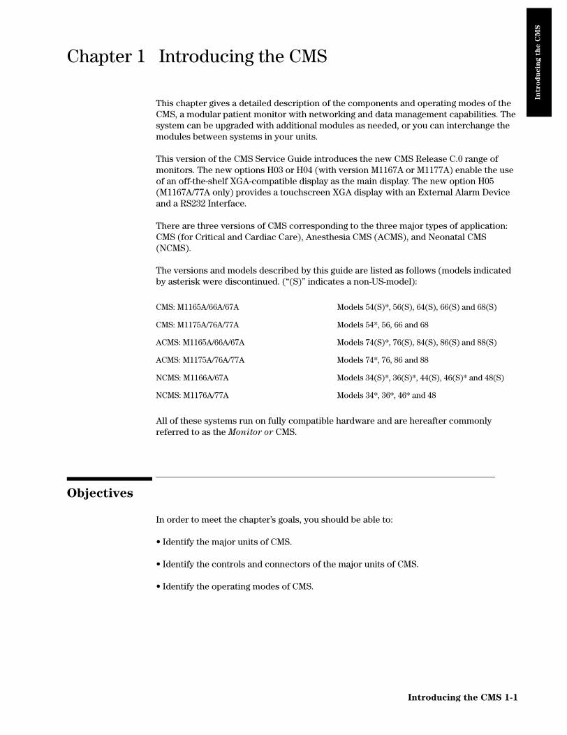
This chapter gives a detailed description of the components and operating modes of the CMS, a modular patient monitor with networking and data management capabilities. The system can be upgraded with additional modules as needed, or you can interchange the modules between systems in your units.
This version of the CMS Service Guide introduces the new CMS Release C.0 range of monitors. The new options H03 or H04 (with version M1167A or M1177A) enable the use of an off-the-shelf XGA-compatible display as the main display. The new option H05 (M1167A/77A only) provides a touchscreen XGA display with an External Alarm Device and a RS232 Interface.
There are three versions of CMS corresponding to the three major types of application: CMS (for Critical and Cardiac Care), Anesthesia CMS (ACMS), and Neonatal CMS (NCMS).
The versions and models described by this guide are listed as follows (models indicated by asterisk were discontinued. (“(S)” indicates a non-US-model):
All of these systems run on fully compatible hardware and are hereafter commonly referred to as the Monitor or CMS.
Objectives
In order to meet the chapter’s goals, you should be able to:
• Identify the major units of CMS.
• Identify the controls and connectors of the major units of CMS.
• Identify the operating modes of CMS.
CMS: M1165A/66A/67A Models 54(S)*, 56(S), 64(S), 66(S) and 68(S)
CMS: M1175A/76A/77A Models 54*, 56, 66 and 68
ACMS: M1165A/66A/67A Models 74(S)*, 76(S), 84(S), 86(S) and 88(S)
ACMS: M1175A/76A/77A Models 74*, 76, 86 and 88
NCMS: M1166A/67A Models 34(S)*, 36(S)*, 44(S), 46(S)* and 48(S)
NCMS: M1176A/77A Models 34*, 36*, 46* and 48
Introducing the CMS 1-1

Concepts
Intro
du
cin
g t
he C
MS
Concepts
CMS Release C.0 contains the following major units:
• Main Display Module - Main Display Modules are 10.4" Flatscreen Color, 14" CRT Color, 14" CRT Mono, or an off-the-shelf XGA-compatible display. The first three have an integrated Control Panel for the human interface; the XGA display option has the External Alarm Device with the Handheld Keypad for the human interface. See page 1-4.
• Independent Display Module - Independent Display Modules can be: 10.4" Flatscreen Color; XGA-compatible display; 14" CRT Color or 14" CRT Mono or 21" CRT Color without Control Panels. These displays are connected to the Computer Module by their own display controller and may display different information than the Main Display Module under software control. See page 1-13.
• Slave Display Module - Slave Display Modules are 14" CRT Color or 14" CRT Mono or 21" CRT Color without Control Panels. These displays can be daisy-chained to any CRT and display the same information as the display they are connected to. See page 1-13.
• Handheld Keypad - The Handheld Keypad is an input device connected to the HIL connector on the Main Display and is used to interact with patient data management and drug calculator software. With the XGA-compatible display options, the External
Alarm Device complements the Handheld Keypad to give a full set of user controls. See page 1-16.
• Computer Module - The Computer Module contains the hardware and software for the processing functions of the monitor. Most of the external connections of the monitor are in the rear of the Computer Module. See page 1-19.
• Integral Power Supply - The Integral Power Supply, located in the new Computer Module (M1046B) in CMS products M1167A and M1177A that have the M1095A flatscreen (or an XGA-compatible) as the main display, provides the power for the Flatscreen Display, Computer Module and satellite-mounted Plug-in Modules. See page 1-51.
• Remote Power Supply - The Remote Power Supply, used with CMS models that have a flatscreen as the Main Display Module and a M1046A Computer Module, provides the power for the Flatscreen Display Module, Computer Module and Plug-in Modules. See page 1-52.
• Plug-in Module Rack (Integral or Satellite) - The Plug-in Module Rack is the interface between the Plug-in Modules and the Computer Module. Plug-in Module Racks can be integrated in the M1046A Computer Module or remotely located in the patient vicinity. See page 1-55.
• Plug-in Modules - The Plug-in Modules are the interface between the patient cables and the Plug-in Module Rack. Each Plug-in Module is responsible for specific types of patient measurement (pressure, temp, and so on). These types of measurement are also known as Parameters. The number and type of Plug-in Modules used will depend on the monitoring situation. See page 1-58.
The CMS monitors can be networked on the Philips Network (also known as SDN). If your system is connected to such a network you can receive information from other Philips monitors or send information to the Philips Central Stations.
1-2 Introducing the CMS

Concepts
Intro
du
cin
g t
he C
MS
Figure 1-1 Philips CMS Patient Monitoring System
MonitoringNetwork
Defibrillator Sync.
(4 or 8 channels in color)
Satellite Racks
Network Interface
Digital Recorder Interface
Main Display
(4-Channel Recorder M1117A)
Independent
Independent Display Interface(color only)
Display
PC
2nd
RS23
2 In
terfa
ce
PrinterM1026A
Gateway
(link to external devices)
(8 or 6 slots)
RS232 Interface
8 Channel
(standard)
Analog Output Interface
RS232 Interfaceto the Ohmeda
7800/7810/7900 VentilatorAnesthetic Gas Module
i-StatCentral
Remote Displays(color or monochrome)
(CRT)
VueLink M1032A
Independent DisplayInterface
(color and monochrome) Or XGA DisplayData Station
M1046B
M1167A/77ACMS (Flatscreen) System Overview
M1165A/66A/75A/76ACMS (CRT) System Overview
PCM1026A
VueLink M1032A
MonitoringNetwork
M1046A with Integral
Defibrillator Sync.
Gateway
Remote Displays
(6 channels in monochrome,4 or 8 channels in color)
(link to external devices)
(8 or 6 slots)
(color or monochrome)
(8 slots)
Satellite Racks
Monitoring Network Interface
RS232 Interface
8 Channel
Digital Recorder Interface
Main Display
i-StatCentral Data Station
(4-Channel Recorder M1117A)
(standard)
Analog Output Interface
Independent
Independent DisplayInterface
(color or monochrome)
Remote Displays(color or monochrome)
Display
RS232 Interfaceto the Ohmeda
7800/7810/7900 VentilatorAnesthetic Gas Module
PC2nd
RS23
2 In
terfa
ce
Printer
Rack
(Flatscreen)
MonitoringNetwork
Defibrillator Sync.
(4 or 8 channels in color)
Satellite Racks
Monitoring Network Interface
Digital Recorder Interface
Main Display
(4-Channel Recorder M1117A)
Independent
Independent Display Interface(color only)
Display
PC
2nd
RS23
2 In
terfa
ce
PrinterM1026A
Gateway
(link to external devices)
(8 or 6 slots)
RS232 Interface
8 Channel
(standard)
Analog Output Interface
RS232 Interfaceto the Ohmeda
7800/7810/7900 VentilatorAnesthetic Gas Module
i-StatCentral
Remote Displays(color or monochrome)
(CRT)
VueLink M1032A
Independent DisplayInterface
(color and monochrome) Or XGA DisplayData Station
M1046B
(Flatscreen)
Introducing the CMS 1-3

Main Display Module
Intro
du
cin
g t
he C
MS
Main Display Module
The Main Display Module of the CMS can be a 10.4" Color flatscreen, a 14" CRT, or an off-the-shelf XGA-compatible display. CRT display-based CMSs can use either a Color CRT Display (M1094B or M1094A) or a Monochrome CRT Display (M1092A) as the Main Display Module. Slave CRT Displays can be daisy-chained from any other CRT displays. Additional independent displays, CRTs and flatscreens can be connected but they need their own display controller in the Computer Module allowing them to show different information than the main display under software control.
The main display (flatscreen or CRT) contains a consistent arrangement of indicators and keys on the Control Panel (human interface). There are two versions of the Control Panel and Handheld Keypad: Standard and Classic. The Classic is no longer available. The Standard Control Panel is available in supported local languages. Slave and independent displays have no Control Panel fitted.
Objective
In order to meet this section’s goals, you should be able to:
• Identify the controls and connectors of the Display Module.
• Be familiar with the function of the controls and connectors of the Display Module.
Concepts
With the exception of Options H03/4, the Main Display Module can be either a flatscreen or CRT with a Control Panel on the front panel or bezel. The bezel contains the Control Panel, as well as the main power switch and the adjustments for brightness and contrast. The rear of the display is referred to as the rear panel and contains the rest of the adjustment controls and all of the connectors. The HIL Connector on the CRT Display is on the lower right-hand corner of the front panel.
Note: With Options H03/4 the Main Display Module is an XGA-compatible display and the Control Panel is the Handheld Keypad with External Alarm Device.
Front Panel of
CRT Main Display
Display Module
Flatscreen Main Display
1-4 Introducing the CMS

Main Display Module
Intro
du
cin
g t
he C
MS
Introducing the CMS 1-5
Front Panel The plastic bezel on the front of the display that contains controls and connectors, including the Control Panel and display adjustments.
Standard
Control Panel
The hardkeys, softkeys and alarm indicators of the Standard human interface (Release E or later). Includes Airway Gas/Ventilation key.
Classic Control
Panel
The hardkeys, softkeys and alarm indicators of the Classic human interface. Available with and without the SUSPEND key (see Parts List). Includes HELP key. The Classic Control Panel is not supported from CMS Release B.0.
HIL Connector The Human Interface Link (HIL) Connector on the Main Display is used to attach the Handheld Keypad and uses Philips HIL protocol to transfer data to the system. The HIL Connector on the CRT Display, which is on the lower right-hand corner of the front panel, can be covered with a plastic insert when not in use.
Softkeys These are blank single-press keys used as selection controls to enter Task Windows. They correspond to the softkey labels displayed above them on the screen.
Hardkeys These are single-press keys with labels used as selection controls. Typically, a hardkey accesses the Selection Window of its label.
Rear Panel The panel on the rear of the display that contains display controls and connectors for power, HIL and video.

Main Display Module
Intro
du
cin
g t
he C
MS
(13.5")337mm
(14.6")370mm (17.8")
451mm
(11")
280mm
(11.9")
302mm
(2.5")63mm
Flatscreen Main Display Module
CRT Main Display Module
(13.2")333,5mm
(16.1")408mm
(3.2")76,7mm
XGA Flatscreen Display Module
1-6 Introducing the CMS

Main Display Module
Intro
du
cin
g t
he C
MS
Figure 1-2 Display Modules with Dimensions
Front Panel Controls and Connectors – CRT Display
The controls and connectors on the front panel of the Display Module are shown below:
Figure 1-3 The Display Module Front Panel
Table 1-1 Display Module Front Panel Controls and Connectors
Controls Function
1 ON/OFF Switch Used to turn the display On/ Off. This is the only power switch for the system and it must be pushed in for power ON.
2 Power ON indicator Green LED, which is lit when the display is switched ON.
3 Contrast Control Rotary control, used to vary the contrast of the display.
4 Brightness Control Rotary control, used to vary the brightness of the display.
MAINSCREEN
CHANGESCEEN
AIRWAYS GASES/VENTILATION
REALTIMERECORD
CONFIRM
HIL
ON/OFF Switch(1)
Power ONIndicator
(2)
ContrastControl
(3)Brightness
Control(4)
HumanInterface Link
(5)
SILENCE /RESET
SUSPEND
ALARMS/VOLUME
OTHER
PATIENTSMONITOR
SETUPPROCEDURES
TRENDS/CALC
MODULE
SETUP
DELAYEDRECORD
PanelControl
(6)
Connector
mar2bb.mif
Introducing the CMS 1-7

Main Display Module
Intro
du
cin
g t
he C
MS
Front Panel Controls and Connectors – Flatscreen Display
The controls on the front panel of the Flatscreen Display are shown below:
Figure 1-4 The Flatscreen Display Front Panel
5 HIL Connector Human Interface Link (HIL) connector is used to connect the Handheld Keypad. This connector may be covered by a plastic insert when not in use.
6 Control Panel User interface of the Display Module.
Table 1-2 Flatscreen Display Front Panel Controls and Connectors
Controls Function
1 ON/OFF Switch Used to turn the display On/Off and used as the remote switch for either the M1047A Remote Power Supply or the M1046B Computer Module integral power supply.
2 Brightness Control Rotary control, used to vary the brightness of the display.
3 Power ON indicator Green LED which is lit when the display is switched ON.
4 Control Panel User interface of the Display Module.
Table 1-1 Display Module Front Panel Controls and Connectors
Controls Function
41
2
3
1-8 Introducing the CMS

Main Display Module
Intro
du
cin
g t
he C
MS
Table 1-3 Standard Control Panel Controls
Controls Function
1 Softkey Selection controls for the softkey labels displayed above them on the screen. Softkeys bring up Task Windows.
2 Alarm Indicators Indicates the color of the alarm: RED and YELLOW.
3 Used to silence an alarm and, if the cause has been eliminated, reset it.
4 Used to switch all alarms on/off.
5 Alarms Off Indicator Indicates that all alarms have been shut off.
6 Used to turn all alarms off/on and individual alarms on/off, adjust alarm limits and volume, limits, show the alarm messages and go to standby mode.
7 Used to view data and alarms between beds.
8 Used to change settings such as screen displays and patient type, setup OxyCRG (Standard CMS only) and recording and make general configuration changes.
9 Used to perform Cardiac Output and Wedge Pressure measurements, make ST segment monitoring adjustments, review ST wave segments, admit and discharge patients, or end particular patient case and transfer patient data.
10 Used to view data in graphs and tables, do physiological calculations in graphs, print reports and mark events to view in graphs.
11 Used to set up and change settings for all modules that are plugged into the CMS.
12 Used to return the standard monitoring screen.
13 Used to freeze waves on the screen and change between screen layouts.
14 Used to start a realtime preset recording or a realtime selected recording.
15 Used to start a delayed recording.
16 Used to measure airway gases or show ventilator data.
17 Arrow Keys Used to move highlighting and make selections in the Task Windows - only active when lit.
18 Used to confirm that the user input is correct - only active when lit.
50/140
Alarms/ Other Monitor Procedures Trends/ Module
Main Airway GasesRealtime DelayedChange
Confirm
Silence/
Suspend
Setup
Ventilation
Calcs
RecordRecord
Setup
ScreenScreen
Volume PatientsReset
wclo12a7.tif
Softkeys (1)
Hardkeys (6-16)
Alarm Indicators (2)
(3) (4) Arrow Keys (17)
(18)
(5)
Silence/ Reset
Suspend
Alarms/Volume
Other Patients
Monitor Setup
Procedures
Trends Calc
Module Setup
Main Screen
Change Screen
Realtime Record
Delayed Record
Airway GasesVentilation
Confirm
Introducing the CMS 1-9

Main Display Module
Intro
du
cin
g t
he C
MS
Table 1-4 Classic Control Panel Controls
Controls Function
1 Softkey Selection controls for the softkey labels displayed above them on the screen. Softkeys bring up Task Windows.
2 Alarm Indicators Indicates the color of the alarm: RED and YELLOW.
3 Used to silence an alarm and, if the cause has been eliminated, reset it.
4 used to switch all alarms on/off.
5 Alarms Off Indicator Indicates that all alarms have been shut off.
6 Used to turn all alarms off/on and individual alarms on/off, adjust alarm limits, show the alarm messages and go to standby mode.
7 Used to view data and alarms between beds.
8 Used to setup OxyCRG and recording, change between main screens and combinations of OxyCRG or Split Screen Trending, or to make general configuration changes.
9 Used to perform Cardiac Output and Wedge Pressure measurements, review ST wave segments, admit and discharge patients, or transfer patient data.
10 Used to view data in graphs and tables, do physiological calculations in graphs and print reports.
11 Used to setup and change settings for all modules that are plugged into the CMS.
12 Used to return to the standard monitoring screen.
13 Used to freeze the screen.
14 Used to display softkeys to mark events you can view in graphs and softkeys for cal signals.
15 Used to display softkeys to make delayed recordings or realtime recordings.
16 Used to provide information about tasks. NOTE: HELP below softkey label on screen points to item you will get help for.
17 Arrow Keys Used to move highlighting and make selections in the Task Windows - only active when lit.
18 Used to confirm that the user input is correct - only active when lit.
50/140
Alarms Overview Instrument Monitoring Patient
Standard HelpMarkCapture
Confirm
Silence/
Suspend
ParametersData
RecordEvent
Config
ScreenDisplay
Reset
wclo12a7.tif
Softkeys (1)
Hardkeys (6-16)
Alarm Indicators (2)
(3) (4) Arrow Keys (17)
(18)
(5)
Procedures
Silence/ Reset
Suspend
Alarms
Overview
Instrument Config
Monitoring Procedures
Patient Data
Parameters
Standard Display
Capture Screen
Mark Event
Record
Help
Confirm
1-10 Introducing the CMS

Main Display Module
Intro
du
cin
g t
he C
MS
Rear Panel Controls and Connectors
Figure 1-5 Rear Panel of the M1094B Display Module
Table 1-5 Main CRT Display Rear Panel Control and Connectors
Controls and Connectors Function
1 Video Termination Switch Used to terminate the video signal at this display. This must be switched to the 75Ω position if only a main display is used. When a remote display is connected, the video termination switch on the main display must be switched to High Imp.
2 V AMP Vertical amplitude control, used to adjust the height of the displayed video.
3 V SHIFT Vertical shift control, used to adjust the vertical position of the displayed video.
4 H AMP Horizontal amplitude control, used to adjust the width of the displayed video.
5 EAST WEST Used to adjust the pin-cushion effect of the displayed video.
6 Fuse Holders Two fuse holders for the line protection fuses, one for the higher operating voltage range and one for the lower operating voltage range.
7 Local Power Connector 3-pin connector, used to input the local line voltage.
8 System Power Connector 15-pin “D” type connector, used to output the 60V dc supply to a similar connector on the DC/DC converter in the rear of the Computer Module.
9 Video In Connector 9-pin “D” type connector, used to input the video signal to be displayed from the display controller in the Computer Module (DSPC for monochrome or CDSPC-Video for color).
10 Video Out Connector 9-pin “D” type connector, used to output the video signal to be displayed on a slave display.
System Power
Equipotential Grounding
Local Power Connector
Fuses
Human Interface
Video Out Connector (10)
Video In Connector (9)
Video Termination Switch (1)
Connector(8)
(7)
(6)
Link Connector(11)
V AMPV SHIFT H AMPEAST WEST(2)(3) (4)(5)
LOCATED ON RIGHT SIDE OF DISPLAYTerminal (12)
rear1
Introducing the CMS 1-11

Main Display Module
Intro
du
cin
g t
he C
MS
Figure 1-6 Rear Panel of the M1092A & M1094A Main Display Modules
11 Human Interface Link Connector
Human Interface Link (HIL) connector, used to output the information from the Control Panel and the Handheld Keypad to the Utility CPU function card in the Computer Module.
12 Equipotential Grounding Terminal
Grounding stud connector, used to connect the Display Module to an equipotential grounding system, if required. The overall system is normally grounded at the grounding terminal on the Computer Module.
Table 1-5 Main CRT Display Rear Panel Control and Connectors
Controls and Connectors Function
M1092A
HIL
CAUTION ATTENTION
VORSICHT CUIDADO
VIDEO
VIDEO
HIGHIMP.
75
LimitedMEDICALEQUIPMENT
x x x x x x
UL LR 49394
CSA R
STANDARD NORME
CATEGORIEDE RISQUES
RISA CLASS
C22 NO 12b tuv
GS
N FI 871-8
U
U
U
U
System PowerConnector
(8)
Local PowerConnector
(7)
Grounding Terminal(12)
Fuses(6) V AMP
(2)V SHIFT
(3)
H AMP(4)
EAST WEST(5)
Equipotential 90 x 120
mar5b
Human Interface LinkConnector
(11)
Video OutConnector
(10)
Video TerminationSwitch
(1)
Video INConnector
(9)
1-12 Introducing the CMS

Slave Display Module
Intro
du
cin
g t
he C
MS
Figure 1-7 Rear Panel of the M1095A Main Display Module
Slave Display Module
Table 1-6 Flatscreen Rear Panel Controls and Connectors
Controls and Connectors Function
1 Brightness Control Adjusts the brightness of the display.
2 ON/OFF Switch Used to turn the display On/Off and used as the remote switch for either the M1047A Remote Power Supply or the M1046B Computer Module integral power supply.
3 Combined Video In / Power Connector
This is a male SCSI connector with 25 pin pairs used to input the video signal and the 60 V DC line voltage.
4 Human Interface Link Connector In
This Human Interface Link (HIL) connector is used to connect the handheld keypad.
5 Human Interface Link Connector Out
This Human Interface Link (HIL) connector is used to output the information from the handheld keypad and control panel to the Utility CPU function card in the computer module.
Introducing the CMS 1-13

Slave Display Module
Intro
du
cin
g t
he C
MS
In
wi
witF
The CMS supports additional displays as either CRT Slave or Flatscreen and CRT Independent Display Modules. CRT Slave Displays connect directly to any CRT and display the same information as the CRT they are connected to. Independent Displays have their own display controller in the Computer Module and may display different information than the Main Display under software control. Slave and Independent Displays are intended as a visual reference and do not have a Control Panel. The information on the 21" slave display can be found in its accompanying manual. See also the Appendix, “Remote 21" Displays”.
14" Slave Display Front Panel Controls
14" Slave Display Rear Panel Controls and Connectors
Table 1-7 Slave Display Front Panel Controls
Controls Function
ON/OFF Switch Push button switch, used to turn the slave display ON and OFF. This must be pushed in for power ON.
Power ON indicator Green LED which is lit when the display is switched ON.
Brightness Control Rotary control, used to vary the brightness of the display.
Contrast Control Rotary control, used to vary the contrast of the display.
Table 1-8 Slave Display Rear Panel Controls and Connectors
Controls and Connectors Function
Video Termination Switch Push button switch, used to terminate the video signal at this display. This switch must be ON (in) or 75Ω if the slave display is the last in the chain. Otherwise the switch must be OFF (out) or High Imp.
Fuse Holders Holders for the line protection fuses.
Local Power Connector 3-pin connector, used to input the local line voltage.
Video In Connector Male 9-pin “D” type connector, used to input the video signal to be displayed from the main Display Module.
Video Out Connector 9-pin “D” type connector, used to output the video signal to be displayed on another Slave Display Module.
Equipotential Grounding Terminal
Grounding stud connector, used to connect the system to an equipotential grounding system.
dependent / Slave
thout Control PanelCRT Display
hout Control Panellatscreen Display
Independent
1-14 Introducing the CMS

Slave Display Module
Intro
du
cin
g t
he C
MS
Figure 1-8 Slave Display Controls and Connectors
EQUIPOTENTIAL GROUNDING
LOCAL POWER CONNECTOR
FUSES
VIDEO OUT CONNECTOR
VIDEO IN CONNECTOR
VIDEO TERMINATION SWITCH
TERMINAL
ON/OFF SWITCH
POWER ON INDICATOR
BRIGHTNESS CONTROL
CONTRAST CONTROL
M1092A
HIL
CAUTION ATTENTION
VORSICHT CUIDADO
VIDEO
VIDEO
HIGHIMP.
75
LimitedMEDICALEQUIPMENT
x x x x x x
UL LR 49394
CSAR
ST ANDARD NORME
CATEGORIEDE RISQUES
RISA CLASS
C22 NO 12b tuv
GS
N FI 871-8
U
U
U
U
LOCAL POWERCONNECTOR
GROUNDING TERMINAL
FUSES
EQUIPOTENTIAL 90 x 120
mar5b
VIDEO OUT CONNECTOR
VIDEO TERMINATION SWITCH
VIDEO IN CONNECTOR
Rear Panel of M1094B
Rear Panel of M1092A and M1094A
Front Panel
Introducing the CMS 1-15

Handheld Keypad
Intro
du
cin
g t
he C
MS
Handheld Keypad
The Handheld Keypad of the CMS is an external device used for inputting patient information and working with the drug calculator that is a part of the monitor. There are three released versions of the Handheld Keypad. The first release (M1106A) is called the Classic Handheld Keypad. The second release (M1106B) added the SUSPEND hardkey to the Classic Handheld Keypad. The current release (M1106C) is called the Standard Handheld Keypad and it contains the same number of keys as the M1106B but improves on the hardkey key labels and functionality to make them more user-friendly.
Note: Only the Standard Handheld Keypad (M1106C) is supported with Release B.0. The Classic Handheld Keypad (M1106A or M1106B) is not supported for use with Release B.0.
Objective
In order to meet this section’s goals, you should be able to:
• Identify the controls and connectors of the Handheld Keypad.
• Be familiar with the function of the controls and connectors of the Handheld Keypad.
Concepts
The Handheld Keypad provides remote access to all monitoring tasks. There are 55 domed buttons on the membrane keyboard which provides a fluid seal to make cleaning easier. A coiled cable is used to connect the keypad to the master or main display, or to the External Alarm Device.
Membrane
Keypad
The plastic bezel on the front of the Handheld Keypad that contains the controls and connectors, including the Control Panel and alphanumeric keypad.
Standard
Control Panel
The hardkeys, softkeys and alarm indicators of the Standard user interface (Release E or later).
Classic Control
Panel
The hardkeys, softkeys and alarm indicators of the Classic user interface. Available with and without the SUSPEND key (see Parts List).
HIL Connector Human Interface Link (HIL) Connector is used to connect the Handheld Keypad to the Main Display, or to the External Alarm Device. Information is transferred to the system using Philips HIL protocol.
Alphanumeric
Keys
These are single-press keys used to input patient information and drug calculations into the monitor.
Handheld Keypad
1-16 Introducing the CMS

Handheld Keypad
Intro
du
cin
g t
he C
MS
Handheld Keypad Membrane Keyboard
All of the softkeys and hardkeys on the Display Module are also found on the Handheld Keypad. See Table 1-3 and Table 1-4 and for descriptions of these keys. In addition, the Philips Handheld Keypad has keys for alphanumeric data entry.
Figure 1-9 Handheld Keypad Controls and Connector
Table 1-9 Handheld Keypad Standard Control Panel
Standard Control Panel Function
Used to enter spaces between numbers or letters
Used to switch between alpha and numeric mode. The LED is lit when keypad is in alpha mode.
Alphabet Characters (A - Z) These characters can be entered only in alpha mode (when the LED on the Shift key is lit).
Punctuation Marks (, .) The punctuation marks can be entered only in numeric mode (when LED on Shift key is not lit).
Numeric Characters (0 - 9) These characters can be entered only in numeric mode (when LED on Shift key is not lit).
Arithmetic Operators (+ - * /) These characters can be entered only in numeric mode (when LED on Shift key is not lit).
Decimal Point (.) The decimal point can be entered only in numeric mode (when LED on Shift key is not lit).
Handheld Keypad Connector (Philips-HIL)
This connector fits into the Philips-HIL connector on the lower right corner of the Display Module.
M1106C
Main
Alarms/ Other MonitorProcedures
Trends/ Module
Change Realtime Delayed Airway Gases/
ConfirmSilence/
Reset
Space
Shift
A B C D E
F G H I J
K L M N O P Q R S
T U V W X Y Z . ,
7 8 9
4 5 6
1 2 3
0 .+
-
X
-..
Space
Suspend
Volume
Screen
Patients
Screen
Setup
Record Record
Calcs Setup
Ventilation
210/140
Standard
keypada1
Arrow Keys
Confirm Key
AlphanumericSpace Key
Shift Key
Suspend Key
Handheld KeypadConnector
HardkeysSilence/ResetKey
Keys
Softkeys
Space
Shift
Introducing the CMS 1-17

Handheld Keypad
Intro
du
cin
g t
he C
MS
Handheld Keypad Rear Cover
The rear cover of the Handheld Keypad contains a magnet to secure it to the keypad mounting bracket or to the External Alarm Device.
External Alarm Device M1109A
The External Alarm Device, for use with off-the-shelf XGA displays, provides visual and audible alarm indicators. It has a bracket to hold the Handheld Keypad. It also provides an on/off switch to remotely control the M1046B CMS Computer Module.
CAUTION Always locate this device in such a way that the speaker at the rear and the lights
on the front are not blocked.
eadevice.hpg
Red Alarm
Yellow Alarm
Alarms-Off indicator
Remote On-Off
HIL to Computer Module
HIL to Keypad
Keypad
Universal Mounting Clamp
On-Off Switch to Computer Module
Green LED
indicator
indicator
Mounting Bracket
1-18 Introducing the CMS

Computer Module
Intro
du
cin
g t
he C
MS
Com
w
Com
wi
Com
wi
Computer Module
The Computer Module of the CMS contains the hardware and software for the processing functions of the monitor. It can be thought of as the heart of the system. It distributes all the power, clocks and data for the whole system. There are several released configurations for the function cards of the Computer Module. Your configuration will depend on the version of software and hardware your monitor is running and the options it is supporting. All of the function cards connect to the Computer Module backplane, whether from the front or from the rear of the unit. Function cards that require external connections are located in the rear of the Computer Module.
Objective
In order to meet this section’s goals, you should be able to:
• Identify the connectors of the Computer Module
• Be familiar with the functions of the Computer Module.
Concepts
The Computer Module of CMS is not fitted with any controls, just connectors. The front of the M1046A Computer Module can be mounted with an integral plug-in module rack or a blank rack. Each rack contains an internal rack connector used to output information from the rack to the Rack Interface function card placed in slot 18 of the computer module. All of the other connections for the Computer Module are in the rear and will depend on the options and revision of your monitor.
Integral Plug-in
Module Rack
The integral plug-in module rack fits in the front of the Computer Module (M1046A) and holds plug-in modules. It contains a rear connector that is used to output information from the rack to the Computer Module.
Blank Rack The blank rack is used to cover the front of the Computer Module (M1046A) when a satellite plug-in module rack is being used. It contains a rear connector that is used to output information from the rack to the Computer Module.
Integral Power
Supply
The integral power supply is used to power the Computer Module (M1046B), a satellite plug-in module rack, and a flatscreen main display without the need for a Remote Power Supply. It connects to the REMOTE_SWITCH card in the Computer Module to allow the flatscreen display to control the Computer Module power.
Backplane The backplane of the Computer Module contains the connections for the front and rear function cards.
puter Module (M1046A)
ith integral rack
puter Module (M1046A)
th integral blank rack
puter Module (M1046B)
th integral power supply
Introducing the CMS 1-19

Computer Module
Intro
du
cin
g t
he C
MS
CPC Flash Port This port is located on the Configurable Processor Card (CPC) in slot 12 and is the connector for the CPC Programming Tool.
Figure 1-10 Computer Module Dimensions
Brief Functional Overview
The Philips CMS Patient Monitoring System is a loosely coupled multi-processor system containing several CPU cards. They can communicate with each other but do not have access to each other’s memory. They can only exchange information in the form of messages.
The backplane can be functionally sectioned into three logical parts or buses, the Message Passing Bus, the Local Bus and the Utility Bus.
Message Passing
Bus
This is the global communication bus for the system, and is used for communications between CPU cards as well as to intelligent interface cards (for example, RS232 Interface and the display controllers). This bus appears on all the connectors.
Local Bus This is the local communication system. It is a buffered processor bus that allows access to local memory cards, SRAM and EPROM that contain software for the exclusive use of the master processor.
The local bus appears on all the connectors on the backplane but is interrupted to connect groups of connectors into local clusters.
M1046A with Integral Rack & Parameter ModulesM1046A with Integral Blank Rack
(19.3")491mm
(14.6")370mm
(6.2")156mm
(14.6")370mm (17.8")
451mm
(6.2")156mm
M1046B with Integral Power Supply
(6.2")156mm
(14.6")370mm (17.8")
451mm
1-20 Introducing the CMS

Computer Module
Intro
du
cin
g t
he C
MS
Utility Bus This includes functions required by the whole system; for example, power and clock signal distribution. This bus appears on all the connectors.
Local Clusters The local bus is connected to all the connectors in the backplane but it is interrupted to form clusters that share a connection to the same local bus. There are 10 local clusters in the backplane with varying numbers of connectors.
Delivered Configurations
The versions and models described by this guide are listed as follows (models indicated by asterisk were discontinued. “(S)” indicates a non-US-model):
The CMS products M1167A and M1177A use the Computer Module (M1046B).
There are three types of Application CPU Cards used in the Systems: M1054 (10 MHz) and M1051 (15 MHz) and M1053 (40 MHz CPC Card).
Function Card placement in the Backplane is dependent upon the variant of the System and the type of Application CPU Cards. Card placements for all variants of the CMS are illustrated in Table 1-10 Function Card Placement on page 1-23
Function Cards of the Computer Module
The function cards are interconnected by the backplane within the Computer Module; refer to the Concepts Guide for a full functional description of the backplane and its theory of operation. The function cards are mounted on both sides of the backplane and may be located either in the front of the Computer Module (even-numbered connectors) or the rear (odd-numbered connectors). The local clusters of the backplane are color-coded on the Computer Module, so that they can be easily identified. On the rear of the backplane, to the left of connector 21, there is a triple-sized gap. This is the only place where the dc-dc converter can be located.
The newer Computer Module (M1046B) has an integral power supply. As a result these Computer Modules have additional function cards. These additional cards are described in Table 1-10 Function Card Placement on page 1-23.
CMS: M1165A/66A/67A Models 54(S)*, 56(S), 64(S), 66(S) and 68(S)
CMS: M1175A/76A/77A Models 54*, 56, 66 and 68
ACMS: M1165A/66A/67A Models 74(S)*, 76(S), 84(S), 86(S) and 88(S)
ACMS: M1175A/76A/77A Models 74*, 76, 86 and 88
NCMS: M1165A/66A/67A Models 34(S)*, 36(S)*, 44(S), 46(S)* and 48(S)
NCMS: M1175A/76A/77A Models 34*, 36*, 46* and 48
Introducing the CMS 1-21

Computer Module
Intro
du
cin
g t
he C
MS
Function Card Placement
Function Card Placement in the backplane of the Philips monitor is dependent upon the following (“(S)” indicates the non-US-models):
1.The monitor model:
•CMS: Models 54 (S), 56 (S), 64 (S), 66 (S), 68 (S)
•ACMS: Models 74 (S), 76 (S), 84 (S), 86 (S), 88 (S)
•NCMS: Models 36 (S), 44 (S), 46 (S), 48 (S)
2.Type of processor cards used:
•10 MHz CPU cards M1054-66501
•15 MHz CPU cards M1051-66501
•40 MHz CPC card M1053-66515
3.Type and combination of display controllers used:
•M1066-66501 DSPC (Monochrome)
•M1066-66531 DSPC (Monochrome)
•M1066-66543 DSPC (Monochrome with integrated DSPC-lang)
•M1072-66521 CDSPC-CTRL (Color) together with M1072-66501 CDSPC-VIDEO
•M1072-66531 CDSPC (Color)
•M1072-66543 (Color with integrated DSPC-lang)
•M1074-66501 DSPC-FLAT (Flatscreen color)
•M1074-66502 DSPC-FLAT (Flatscreen color)
•M1074-66503 DSPC-FLAT (Flatscreen Color with integrated DSPC-lang)
•M1075-66503 XGA DSPC (XGA with integrated DSPC-lang)
1-22 Introducing the CMS

Computer Module
Intro
du
cin
g t
he C
MS
Use the following tables to determine the location of the function cards for your system.
Table 1-10 Function Card Placement
Software Release A
1
3
5
7
9
2
4
6
8
1011
13
15
17
19
12
14
16
18
2021
22
24
Front Slots Rear Slots
Yellow
Gray
Blue
Red
Green
Blue Strips
Red Strips
Green StripsDC-DC Converter
1
3
5
7
9
2
4
6
8
1011
13
15
17
19
12
14
16
18
2021
22
24 DC/DC CONVERTER
FRONT REAR
DSPC or
APP_CPU
BLANK or
EPROM MASTER
APP_CPU
SRAM
EPROM SLAVE
APP_CPU
RS232_IF (if present)
UTIL_CPU
SDN_IF (if present)
APP_CPU
RACK_IF
HDLC_IF (If present)
APP_CPU(Model 68 only)
CDSPC_CTRLCDSPC_VIDEO
200 x 90
Using 10MHz Application CPUs
DSPC #2 or
CDSPC_VID #2
CDSPC_CTRL #2
Rel_a.mif
1
3
5
7
9
2
4
6
8
1011
13
15
17
19
12
14
16
18
2021
22
24 DC/DC CONVERTER
APP_CPUEPROM MASTER
SRAM
EPROM SLAVE
APP_CPU
RS232_IF (if present)
UTIL_CPU
SDN_IF (if present)
APP_CPU
RACK_IF
HDLC_IF (if present)
APP_CPU(Model 68 only)
FRONT
BLANK or
CDSPC_CTRL
REAR
DSPC or
CDSPC_VIDEO
Using 15MHz Application CPUs
DSPC #2 or
CDSPC_VID #2
CDSPC_CTRL #2
Introducing the CMS 1-23

Computer Module
Intro
du
cin
g t
he C
MS
Software Release B
Software Release C (15 MHz APP_CPUs)
Table 1-10 Function Card Placement
1
3
5
7
9
2
4
6
8
1011
13
15
17
19
12
14
16
18
2021
22
24 DC/DC CONVERTER
FRONT REAR
DSPC or
APP_CPU
BLANK or
EPROM MASTER
APP_CPU
SRAM
EPROM SLAVE
APP_CPU
RS232_IF (if present)
UTIL_CPU
SDN_IF (if present)
APP_CPU
RACK_IF
HDLC_IF (If present)
APP_CPU(Model 56 with #C10,
CDSPC_CTRLCDSPC_VIDEO
ANALOG_IF (if present)66 with #C10, or 68)
DSPC_KANJI (if present)
Using 10MHz Application CPUs
DSPC #2 or
CDSPC_VID #2
CDSPC_CTR #2
1
3
5
7
9
2
4
6
8
1011
13
15
17
19
12
14
16
18
2021
22
24 DC/DC CONVERTER
APP_CPUEPROM MASTER
SRAM
EPROM SLAVE
APP_CPU
RS232_IF (if present)
UTIL_CPU
SDN_IF (if present)
APP_CPU
RACK_IF
HDLC_IF (if present)
APP_CPU(Model 68 only)
FRONT
BLANK orCDSPC_CTRL
REAR
DSPC or
CDSPC_VIDEO
ANALOG_IF (if present)
DSPC_KANJI (if present)
200 x 90Using 15MHz Application CPUs
CDSPC_CTR #2DSPC #2 or
CDSPC_VID #2
Rel_b.mif
1
3
5
7
9
2
4
6
8
1011
13
15
17
19
12
14
16
18
2021
22
24 DC/DC CONVERTER
FRONT REAR
DSPC #1 or
15 MHz APP_CPU
BLANK or
EPROM MASTER
SRAM
EPROM SLAVE
15 MHz APP_CPU
RS232_IF
UTIL_CPU
SDN_IF
APP_CPU
RACK_IF
CDSPC_CTRL #1CDSPC_VID #1
ANALOG_IF
DSPC_LANG (KANJI, TAI or PRC)
DSPC #2 or
CDSPC_VID #2
HDLC-IF
CDSPC_CTRL #2
Models 54(S)/64(S) and Models 56(S)/66(S) without #C26
15 MHz APP_CPU
200 x 90
1
3
5
7
9
2
4
6
8
1011
13
15
17
19
12
14
16
18
2021
22
24 DC/DC CONVERTER
FRONT REAR
DSPC #1 or
15 MHz APP_CPU
BLANK or
EPROM MASTER
SRAM
EPROM SLAVE
15 MHz APP_CPU
UTIL_CPU
SDN_IF
15 MHz APP_CPU
RACK_IF
DSPC #3 (only 68(S))
CDSPC_CTRL #1CDSPC_VID #1
ANALOG_IF
DSPC_LANG.(KANJI, TAI or PRC)
15 MHz APU_CPU
DSPC #2 or
CDSPC_VID #2
RS232_IF #2 or
HDLC_IF
CDSPC_CTRL #2
Models 56(S)/66(S) with #C26 and Model 68(S)
RS232_IF #115 MHz APU_CPU
1-24 Introducing the CMS

Computer Module
Intro
du
cin
g t
he C
MS
Upgrade Backplane to Release C (without CPC)
The table below shows the slot locations and quantity of10 MHz (M1054-66501) and 15 MHz (M1051-66501) APP_CPUs for those Philips CMS Patient Monitoring System that have been upgraded from software release A or B with 10 MHz CPU’s exclusively, to software release C without CPC.
APP_CPU Slot Location and Quantity
Software Release C+ or D (40 MHz CPC)
Table 1-10 Function Card Placement
A54S/A66S 51, 8, 11, 14, 22
A56S,/A66S 51, 8, 11, 14, 22
A56(S)/A66(S) (#C10) 51, 8, 11, 14, 162, 22
A56(S)/A66(S) (#C26) 51, 8, 11, 14, 161, 22
1 This is a 15 MHz CPU.2 The systems that have been upgraded from
software release B to software release C with existing C10 will contain a 10 MHz processor in slot 16. If C10 is added to a Software Release C monitor, there will not be a 10 MHz processor in slot 16.
Rel. C+ to Rel. G 15 MHz APP_CPU Requirements
Model Slot 22 Slot 4
Standard CMS
A68(S) Required Extra card
A56(S)/A66(S) Requireda
a. Not required in certain earlier releases.
Extra card
A54(S)/A64(S) Extra card Extra card
Anesthesia CMS (from Rel. Eß)
A88(S) Required Required
A76(S)/A86(S) (#C25) Required Required
A76(S)/A86(S) without (#C25) Extra card Extra card
A74(S)/A84(S) (#C24) Required Extra card
A74(S)/A84(S) w/o (#C24) Extra card Extra card
Neonatal CMS (from Rel. F)
A36(S)/A46(S)/A48(S) Required Extra card
1
3
5
7
9
2
4
6
8
1011
13
15
17
19
12
14
16
18
2021
22
24 DC/DC CONVERTER
FRONT REARDSPC #1 or
BLANK or
RS232_IF
UTIL_CPU
SDN_IF
RACK_IF
HDLC_IF
ANALOG_IF
CDSPC_CTRL #1
CDSPC_CTRL #2
CDSPC_VID #1
DSPC_LANG
(KANJI, TAI or PRC)
DSPC #2 or
CDSPC_VID #2
Models 54(S)/64(S) and Models 56(S)/66(S)
200 X 90
15 MHz APP_CPU *
15 MHz APP_CPU *
40 MHz CPC
1
3
5
7
9
2
4
6
8
1011
13
15
17
19
12
14
16
18
2021
22
24 DC/DC CONVERTER
FRONT REARDSPC #1 or
BLANK or
RS232_IF #2 or
UTIL_CPU
SDN_IF
RACK_IF
HDLC_IF
15MHz APP_CPU
ANALOG_IF
CDSPC_CTRL #1
CDSPC_CTRL #2
CDSPC_VID #1
DSPC_LANG
(KANJI, TAI or PRC)
DSPC #2 or
CDSPC_VID #2
Models 56(S)/66(S) with #C26 and Model 68(S)
DSPC #3 (only 68(S))
RS232_IF #1
200 X 90
* An extra CPU may be left in for future use.
15 MHz APP_CPU *
40 MHz CPC
Introducing the CMS 1-25

Computer Module
Intro
du
cin
g t
he C
MS
Software Release E or Eß Software Release F
Software Release G
Table 1-10 Function Card Placement
1
3
5
7
9
2
4
6
8
1011
13
15
17
19
12
14
16
18
2021
22
24 DC/DC CONVERTER
FRONT REAR
DSPC #1 orBLANK or
ANALOG_IF or
UTIL_CPU
SDN_IFRACK_IF
CDSPC_CTRL #1CDSPC_VIDEO #1
DSPC_LANG #1(KANJI, TAI or PRC)
40 MHz CPC
DSPC #2 orCDSPC_VIDEO #2
CDSPC_CTRL #2
25
DSPC #3 (only model 88)
RS232 IF #2
HDLC_IF
15 MHz APP_CPU
15 MHz APP_CPU
RS232_IF #1
1
3
5
7
9
2
4
6
8
1011
13
15
17
19
12
14
16
18
2021
22
24 DC/DC CONVERTER
FRONT REAR
DSPC #1 or
* BLANK
ANALOG_IF or
UTIL_CPU
SDN_IFRACK_IF
CDSPC #1 or DSPC_FLAT #1
DSPC_LANG #1(KANJI, TAI or PRC)
40 MHz CPC
DSPC #2 orCDSPC #2 or DSPC_FLAT #2
CDSPC_CTRL #2
100/140
25
DSPC #3 or DSPC_FLAT #3
RS232 IF #2
HDLC_IF
15 MHz APP_CPU
15 MHz APP_CPU
RS232_IF #1
bacone1.tif
or CDSPC #3 (only model 88)
* If upgraded (to F) may still have CDSPC_CTRL #1.
1
3
5
7
9
2
4
6
8
1011
13
15
17
19
12
14
16
18
2021
22
24 DC/DC CONVERTER
DSPC #1 or
* BLANK
ANALOG_IF or
UTIL_CPU
SDN_IFRACK_IF
CDSPC #1 or DSPC_FLAT #1
DSPC_LANG #1(KANJI, TAI or PRC)
40 MHz CPC
DSPC #2 orCDSPC #2 or DSPC_FLAT #2
CDSPC_CTRL #2
100/140
25
DSPC #3 or DSPC_FLAT #3
RS232 IF #2
HDLC_IF
15 MHz APP_CPU
15 MHz APP_CPU
RS232_IF #1
bacone1.tif
or CDSPC #3 (only model 88)
* If upgraded (to G) may still have CDSPC_CTRL #1.
M1046A Computer ModuleFRONT REAR
1
3
5
7
9
2
4
6
8
1011
13
15
17
19
12
14
16
18
2021
22
24 DC/DC CONVERTER
FRONT REARDSPC_FLAT_NON_ASIA #1 or
BLANK
ANALOG_IF or
UTIL_CPU
SDN_IFRACK_IF
DSPC_FLAT_ASIA #1
40 MHz CPC
DSPC #2 orCDSPC #2 or DSPC_FLAT #2
CDSPC_CTRL #2
100/140
25
DSPC #3 or DSPC_FLAT #3
RS232 IF #2
HDLC_IF
15 MHz APP_CPU
15 MHz APP_CPU
RS232_IF #1
bacone1.tif
or CDSPC #3 (only model 88)
M1046B Computer Module
REMOTE_SWITCH
AUX_CONNECTOR
1-26 Introducing the CMS

Computer Module
Intro
du
cin
g t
he C
MS
Software Releases A.0 to C.0
Table 1-10 Function Card Placement
1
3
5
7
9
2
4
6
8
1011
13
15
17
19
12
14
16
18
2021
22
24 DC/DC CONVERTER
FRONT REAR
DSPC #1 or
ANALOG_IF or
UTIL_CPU
SDN_IFRACK_IF
CDSPC #1 or DSPC_FLAT #1DSPC_LANG #1(JAP, PRC, ROC, GRK, POL,
40 MHz CPC #1
DSPC #2 orCDSPC #2 or DSPC_FLAT #2
100/140
25
DSPC #3 or CDSPC #3
RS232 IF #2
HDLC_IF
40 MHz CPC #2
* 15 MHz APP_CPU
RS232_IF #1
or DSPC_FLAT #3(only model 88)
M1046A Computer Module
RUS, CZE)
Systems with M1066-66531 or M1066-66543** (DSPC) or M1072-66531 or M1072-66543** (CDSPC) or M1074-66501 (DSPC_FLAT) orM1074-66502 (DSPC_FLAT)**
*For future use – if upgraded ** with these controllers no DSPC_LANG is required
1
3
5
7
9
2
4
6
8
1011
13
15
17
19
12
14
16
18
2021
22
24 DC/DC CONVERTER
FRONT REAR
DSPC_FLAT #1or DSPC #1
ANALOG_IF or
UTIL_CPU
SDN_IFRACK_IF
40 MHz CPC #1
DSPC #2 or CDSPC #2 or DSPC_FLAT #2
100/140
25
DSPC #3 or CDSPC #3
RS232 IF #2
HDLC_IF
40 MHz CPC #2
* 15 MHz APP_CPU
RS232_IF #1
or DSPC_FLAT #3(only model 88)
M1046B Computer ModuleSystems with M1074-66501(DSPC_FLAT) or
M1074-66502 (DSPC_FLAT)
DSPC_LANG #1
POL, RUS, CZK)
*For future use – if upgraded
(JAP, PRC, ROC, GRK,
REMOTE
AUX
1
3
5
7
9
2
4
6
8
1011
13
15
17
19
12
14
16
18
2021
22
24 DC/DC CONVERTER
FRONT REAR
DSPC #1 or
ANALOG_IF or
UTIL_CPU
SDN_IFRACK_IF
CDSPC_VIDEO #1
DSPC_LANG(JAP, PRC, ROC)
40 MHz CPC #1
DSPC #2 orCDSPC_VIDEO #2
100/140
25
DSPC #3 (only model 88)
RS232 IF #2
HDLC_IF
40 MHz CPC #2
* 15 MHz APP_CPU
RS232_IF #1
M1046A Computer ModuleSystems with M1066-66501 (DSPC) or
M1072-66521 (CDSPC_CTRL) +M1072-66501 (CDSPC_VIDEO)
CDSPC_CTRL #1
CDSPC_CTRL #2
* For future use – if upgraded.
1
3
5
7
9
2
4
6
8
1011
13
15
17
19
12
14
16
18
2021
22
24 DC/DC CONVERTER
FRONT REAR
XGA_DSPC #1 or DCPC_FLAT #1
ANALOG_IF or XGA_DSPC or
UTIL_CPU
SDN_IFRACK_IF
40 MHz CPC #1
XGA_DSPC #2 or DSPC #2 or CDSPC#2 or DSPC_FLAT #2
100/140
25
DSPC #3 or CDSPC #3
RS232 IF #2
HDLC_IF
40 MHz CPC #2
* 15 MHz APP_CPU
RS232_IF #1
or DSPC_FLAT #3(only model 88)
M1046B Computer ModuleSystems with M1075-66503 (XGA_DSPC) or
M1074-66503 (DSPC_FLAT)
* For future use – if upgraded.
REMOTE
AUX
Introducing the CMS 1-27
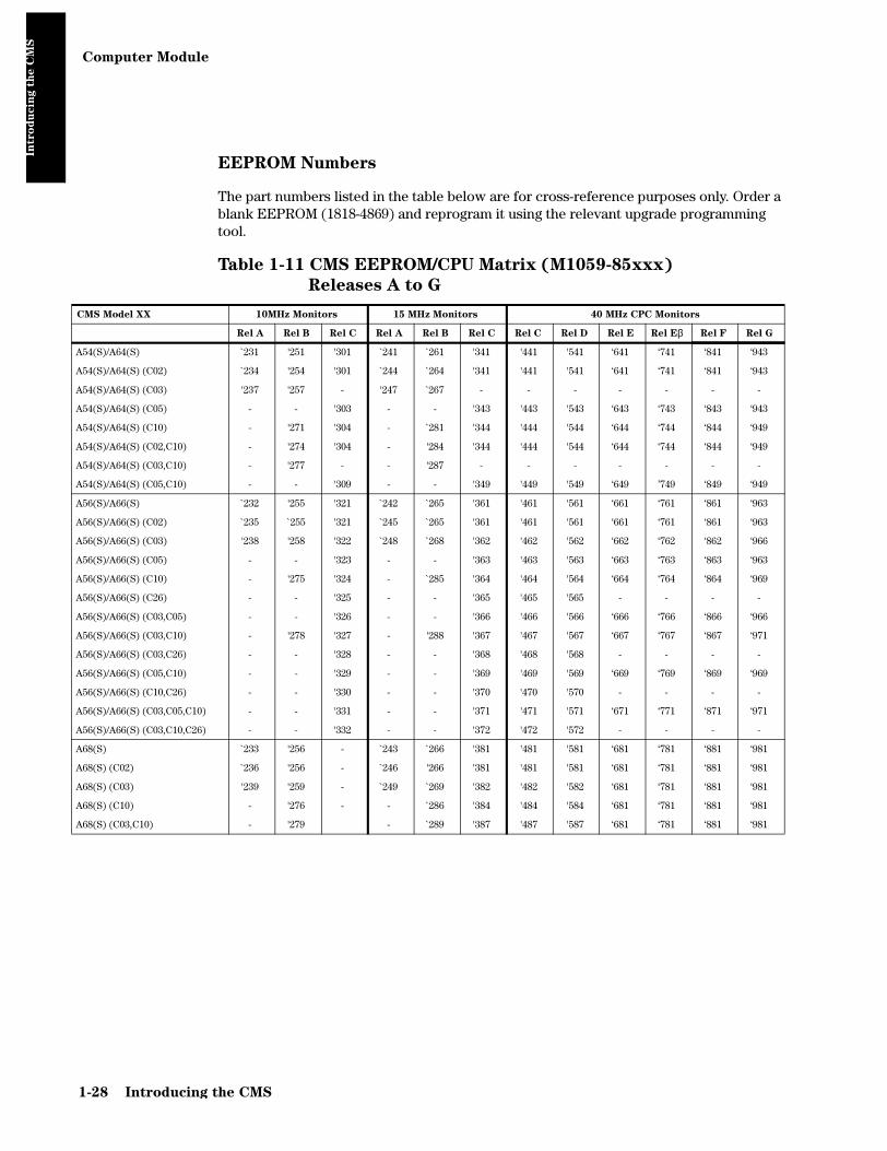
Computer Module
Intro
du
cin
g t
he C
MS
EEPROM Numbers
The part numbers listed in the table below are for cross-reference purposes only. Order a blank EEPROM (1818-4869) and reprogram it using the relevant upgrade programming tool.
Table 1-11 CMS EEPROM/CPU Matrix (M1059-85xxx)
Releases A to G
CMS Model XX 10MHz Monitors 15 MHz Monitors 40 MHz CPC Monitors
Rel A Rel B Rel C Rel A Rel B Rel C Rel C Rel D Rel E Rel Eβ Rel F Rel G
A54(S)/A64(S) `231 '251 '301 `241 `261 '341 '441 '541 ‘641 ‘741 ‘841 ‘943
A54(S)/A64(S) (C02) `234 '254 '301 `244 `264 '341 '441 '541 ‘641 ‘741 ‘841 ‘943
A54(S)/A64(S) (C03) '237 '257 - '247 `267 - - - - - - -
A54(S)/A64(S) (C05) - - '303 - - '343 '443 '543 ‘643 ‘743 ‘843 ‘943
A54(S)/A64(S) (C10) - '271 '304 - `281 '344 '444 '544 ‘644 ‘744 ‘844 ‘949
A54(S)/A64(S) (C02,C10) - '274 '304 - '284 '344 '444 '544 ‘644 ‘744 ‘844 ‘949
A54(S)/A64(S) (C03,C10) - '277 - - '287 - - - - - - -
A54(S)/A64(S) (C05,C10) - - '309 - - '349 '449 '549 ‘649 ’749 ‘849 ‘949
A56(S)/A66(S) `232 '255 '321 `242 `265 '361 '461 '561 ‘661 ‘761 ‘861 ‘963
A56(S)/A66(S) (C02) `235 `255 '321 `245 `265 '361 '461 '561 ‘661 ‘761 ‘861 ‘963
A56(S)/A66(S) (C03) '238 '258 '322 `248 `268 '362 '462 '562 ‘662 ‘762 ‘862 ‘966
A56(S)/A66(S) (C05) - - '323 - - '363 '463 '563 ‘663 ‘763 ‘863 ‘963
A56(S)/A66(S) (C10) - '275 '324 - `285 '364 '464 '564 ‘664 ‘764 ‘864 ‘969
A56(S)/A66(S) (C26) - - '325 - - '365 '465 '565 - - - -
A56(S)/A66(S) (C03,C05) - - '326 - - '366 '466 '566 ‘666 ‘766 ‘866 ‘966
A56(S)/A66(S) (C03,C10) - '278 '327 - '288 '367 '467 '567 ‘667 ‘767 ‘867 ‘971
A56(S)/A66(S) (C03,C26) - - '328 - - '368 '468 '568 - - - -
A56(S)/A66(S) (C05,C10) - - '329 - - '369 '469 '569 ‘669 ‘769 ‘869 ‘969
A56(S)/A66(S) (C10,C26) - - '330 - - '370 '470 '570 - - - -
A56(S)/A66(S) (C03,C05,C10) - - '331 - - '371 '471 '571 ‘671 ‘771 ‘871 ‘971
A56(S)/A66(S) (C03,C10,C26) - - '332 - - '372 '472 '572 - - - -
A68(S) `233 '256 - `243 `266 '381 '481 '581 ‘681 ‘781 ‘881 ‘981
A68(S) (C02) `236 '256 - `246 '266 '381 '481 '581 ‘681 ‘781 ‘881 ‘981
A68(S) (C03) '239 '259 - `249 `269 '382 '482 '582 ‘681 ‘781 ‘881 ‘981
A68(S) (C10) - '276 - - `286 '384 '484 '584 ‘681 ‘781 ‘881 ‘981
A68(S) (C03,C10) - '279 - `289 '387 '487 '587 ‘681 ‘781 ‘881 ‘981
1-28 Introducing the CMS

Computer Module
Intro
du
cin
g t
he C
MS
Table 1-12 CMS EEPROM/CPU Matrix (M1059-xxxxx)
Releases A.0 to C.0
System Model Options Rel. A.0 Rel. B.0 Rel. C.0 Rel. C.1
64/64S Standard -80040 -80140 -80242 -80342C04 -80041 -80141 -80243 -80343C12 — -80142 -80242 -80342C04, C12 — -80143 -80243 -80343C80 -80042 -80140 -80242 -80342C04, C80 -80043 -80141 -80243 -80343
56/56S and 66/66S (Rel.B.0 and C.0)
Standard -80060 -80160 -80262 -80362C04 -80061 -80161 -80263 -80363C12 — -80162 -80262 -80362C04, C12 — -80163 -80263 -80363C80 -80062 -80160 -80262 -80362C04, C80 -80063 -80161 -80263 -80363J26 -80070 -80170 -80272 -80372J26, C04 -80071 -80171 -80273 -80373J26, C32 — — -80274 -80374J26, C04, C32 — — -80275 -80375J26, C12 — -80172 -80272 -80372J26, C04, C12 — -80173 -80273 -80373J26, C80 -80072 -80170 -80272 -80372J26, C04, C80 -80073 -80171 -80273 -80373
68/68S Standard -80080 -80180 -80282 -80382C04 -80081 -80101 -80283 -80383C12 — -80182 -80282 -80382C80 — — -80282 -80382C04, C80 -80083 -80101 -80283 -80383J28 -80090 -80190 -80292 -80392J28, C04 -80091 -80111 -80293 -80393J28, C32 — — -80294 -80394J28, C04, C32 — — -80295 -80395J28, C12 — -80192 -80292 -80392J28, C80 -80092 -80190 -80292 -80932J28, C04, C80 -80093 -80111 -80293 -80393
Introducing the CMS 1-29

Computer Module
Intro
du
cin
g t
he C
MS
Table 1-13 ACMS EEPROM/CPU Matrix (M1059-87xxx)
Rel. E to G
ACMS Model XX 40 MHz CPC Monitors
Rel E Rel Eβ Rel F Rel G
A74(S)/A84(S) ‘641 ‘741 ‘841 ‘943
A74(S)/A84(S) (C05) ‘643 ‘743 ‘843 ‘943
A74(S)/A84(S) (C24) ‘644 ‘744 ‘844 ‘949
A74(S)/A84(S) (C05,C24) ‘649 ‘749 ‘849 ‘949
A76(S)/A86(S) ‘661 ‘761 ‘861 ‘963
A76(S)/A86(S) (C03) ‘662 ‘762 ‘862 ‘966
A76(S)/A86(S) (C05) ‘663 ‘763 ‘863 ‘963
A76(S)/A86(S) (C25) ‘665 ‘765 ‘865 ‘971
A76(S)/A86(S) (C03,C05) ‘666 ‘766 ‘866 ‘966
A76(S)/A86(S) (C03,C25) ‘668 ‘768 ‘868 ‘972
A76(S)/A86(S) (C05,C25) ‘671 ‘771 ‘871 ‘971
A76(S)/A86(S) (C03,C05,C25) ‘672 ‘772 ‘872 ‘972
A88(S) ‘681 ‘781 ‘881 ‘981
A88(S) (C11) - ‘880 ‘980
1-30 Introducing the CMS

Computer Module
Intro
du
cin
g t
he C
MS
Table 1-14 ACMS EEPROM/CPU Matrix (M1059-xxxxx)
Rel. A.0 to C.0
System Model Options Rel. A.0 Rel. B.0 Rel. C.0 Rel. C.1
84/84S (Rel. C.0) Standard — — -81242 -81342C79 — — -81243 -81343
76/76S and 86/86S (Rel.B.0 and C.0)
Standard -81060 -81160 -81262 -81362C79 -81061 -81161 -81263 -81363C12 — -81162 -81262 -81362C12, C79 — -81163 -81263 -81363C80 -81062 -81160 -81262 -81362C80, C79 -81063 -81161 -81263 -81363J26 -81070 -81170 -81272 -81372J26, C79 -81071 -81171 -81273 -81373J26, C12 — -81172 -81272 -81372J26, C12, C79 — -81173 -81273 -81373J26, C80 -81072 -81170 -81272 -81372J26, C79, C80 -81073 -81171 -81270 -81370J26, C32 — — -81274 -81374J26, C79, C32 — — -81275 -81375
88/88S Standard -81080 -81180 -81282 -81382C79 -81081 -81181 -81283 -81383C12 — -81182 -81282 -81382C12, C79 — -81183 -81283 -81383C80 -81082 -81180 -81282 -81382C79, C80 -81083 -81181 -81283 -81383J28 -81090 -81190 -81292 -81392J28, C79 -81091 -81191 -81293 -81393J28, C32 — — -81294 -81394J28, C32, C79 — — -81295 -81395J28, C12 — -81192 -81292 -81392J28, C12, C79 — -81193 -81293 -81393J28, C80 -81092 -81190 -81292 -81392J28, C79, C80 -81093 -81191 -81293 -81393J28, C11 -81095 -81190 -81292 -81392J28, C11, C79 -81096 -81191 -81293 -81393J28, C11, C80 -81097 -81190 -81292 -81392J28, C11, C79, C80 -81098 -81191 -81293 -81393
Introducing the CMS 1-31

Computer Module
Intro
du
cin
g t
he C
MS
Table 1-15 NCMS EEPROM/CPU Matrix (M1059-85xxx)
Releases F and G
NCMS Model XX 40 MHz CPC Monitors
Rel F Rel G
A36(S)/A46(S) ‘860 ‘960
A36(S)/A46(S) (C10) ‘870 ‘970
A48(S) ‘880 ‘980
Table 1-16 NCMS EEPROM/CPU Matrix (M1059-xxxxx)
Releases A.0 to C.0
System
ModelOptions
Rel.
A.0
Rel.
B.0
Rel.
C.0
Rel.
C.1
44/44S Standard — — -80220 -80320
C04 — — -80221 -80321
48/48S Standard -80000 -80100 -80200 -80300
C04 -80001 -80101 -80201 -80301
C80 -80002 -80100 -80200 -80300
C04, C80 -80003 -80103 -80201 -80301
J28 -80010 -80110 -80210 -80310
J28, C04 -80011 -80111 -80211 -80311
J28, C80 -80012 -80110 -80210 -80310
J28, C04, C80 -80013 -80111 -80211 -80311
C32 — — -80214 -80314
C04, C32 — — -80215 -80315
1-32 Introducing the CMS

Computer Module
Intro
du
cin
g t
he C
MS
Front Connectors
The front of the Computer Module contains two function cards with connectors, the Rack Interface card connector in slot 18 and the CPC card connector in slot 12 in later releases. The Rack Interface connector is used to collect output for the Computer Module from the plug-in module rack (integral or blank) and the CPC Flash port is used by the CPC Programming Tool for programming functions. Most models contain a Sheet Metal Cover over the front function cards. The cover has two ports for access to the front connectors.
Figure 1-11 M1046A Computer Module Front Connectors
CPC FLASHPORT
INTEGRAL RACK
SHEET METALCOVERING THE FRONT
FRONT FUNCTION CARDS
RACK INTERFACE CONNECTOR PORT
FUNCTION CARDS
SIT BEHIND SHEET METAL COVER
Introducing the CMS 1-33

Computer Module
Intro
du
cin
g t
he C
MS
Front Connectors on Computer Module M1046B
There are extra connectors on the front of the M1046B Computer Module with an integral power supply.
Remote Switch This connects the integral power supply to the backplane of the computer module and allows the flatscreen display to control the power for the Computer Module.
FE-Link &ECG
sync
These connectors are found on the AUX_CONNECTOR card in slot 24 to allow access to the RACK_IF card in slot 18 behind the power supply. An ECG adapter allows you to connect to the ECG sync connector through a hole in the front plastic cover.
Figure 1-12 M1046B Computer Module Front Connectors
Remote_SwitchConnector
ECG Connector
Rack-IF Connector
FE-LinkConnector
Aux_ConnectorFunction Card
Remote_SwitchFunction Card
Rack_IFFunction Card
ECG Adaptor
FE-Link Connector
CPC Connector
1-34 Introducing the CMS

Computer Module
Intro
du
cin
g t
he C
MS
Rear Connectors
The rear panel of the Computer Module will have several connectors. The number and the type of connectors present is dependent upon which function cards are fitted in the Computer Module backplane. Any unused rear backplane function card slots are fitted with blank slot covers. A typical Computer Module rear panel is shown below.
Table 1-17 Computer Module Rear Connectors
Connector Function
1 System Power Connector (DC/DC Convertor)
15-pin “D”-type connector, used to input the 60V dc from either a Main CRT Display Module or the Remote Power Supply Module if a flatscreen is used as the main display.For M1046B: The 60V dc is supplied from an integral power supply and a shorting stub MUST be installed in this connector for the system to function correctly.Note: Daisychaining is not permitted with the M1046B.
2 Equipotential Grounding Terminal
Used to connect the Computer Module to the hospital's grounding system.
3 SDN Connectors (SDN Interface)
Philips connectors, used to input/output information to/from a SDN network.
4 Human Interface Connector (Utility CPU)
Human Interface Link (HIL) connector, used to input the information from the Control Panel in the Main Display Module and the Handheld Keypad.
5 Nurse Paging Relay output Mini-phone jack, used to connect to the hospital's Nurse Paging System.
6 Analog Interface Connector 37-pin “D” type connector configured as shown in Figure 1-13, used to output information to analog devices.
XGA or
Introducing the CMS 1-35

Computer Module
Intro
du
cin
g t
he C
MS
No connection can be made to the following cards:
• APP_ CPU
• CDSPC_CRTL
• EPROM (including character set EPROMs, for example, Kanji)
• SRAM
Computer Module External Connector Pinouts
The following table lists the signals and appropriate notes for the pins on the Video Out Connector (CRT).
7 RS232 Connectors (RS232 Interface)
Two 25-pin “D” type connectors configured as shown in Figure 1-14, used to output information to a printer or computer systems. Only the upper connector (port 2) can be used to output RS232 information to printers.
8 HDLC Connector Used to connect to a STRIP recorder, M1117A.
9 Video Out Connector (CDSPC-Video or DSPC)
9-pin “D” type connector, used to output information to be displayed on the Display Module. See Table 1-19 on page 1-37 lists the connector pinouts.
10 PS ON/OFF connector (DSPC_Flat or CDSPC-XGA)
Used to control remotely the 60V DC output of the Remote Power Supply Module. For M1046B with an integral power supply, this connector is not used except for the XGA display configuration in which it is connected to the External Alarm Device
11 Video Out Connector (Flatscreen or XGA)
Used to output information to be displayed on the Flatscreen Display Module (25-pin) or XGA Display (15-pin), and also to output 60V DC to the Flatscreen Display Module. Table 1-19 Video / Power Connector on page 1-37 lists the connector pinouts.
Table 1-18 Video Out Connector
Pin\No Signal Notes
1 Sync 1 (H sync - positive TTL level)
2 -
3 Red signal (1 V peak positive)
4 Green signal (1 V peak positive)
5 Blue signal (1 V peak positive)
6 Sync 2 (L sync - positive TTL level)
7 -
8 -
9 Ground
Table 1-17 Computer Module Rear Connectors
Connector Function
NOTE
1-36 Introducing the CMS

Computer Module
Intro
du
cin
g t
he C
MS
The following table lists the signals for the pins on the Video Out connector (M1095A Flatscreen). For the Video/Power input a male ‘SCSI’ connector with 25-pin pairs is used.
Note that an XGA display uses a standard 15-pin connector.
Table 1-19 Video / Power Connector
Pin Pair Signal
1 / 26 Red 0
2 / 27 Red 1
3 / 28 Red 2
4 / 29 Red 3
5 / 30 Green 0
6 / 31 Green 1
7 / 32 Green 2
8 / 33 Green 3
9 / 34 Blue 0
10 / 35 Blue 1
11 / 36 Blue 2
12 / 37 Blue 3
13 / 38 HSYNC
14 / 39 VSYNC
15 / 40 BLANK
16 / 41 Backlight ON/OFF
17 / 42 ID_0 / ID_1
18 / 43 ID_2 / ID_GND
19 / 44 Pixel Clock
20 / 45 GND
21 / 46 free
22 / 47
23 / 48 FEPWR / FECOM (+60V)
24 / 49 FEPWR / FECOM (+60V)
25 / 50 Remote ON/OFF to Power Supply
Note: The shaded areas are differential signals.
Introducing the CMS 1-37

Computer Module
Intro
du
cin
g t
he C
MS
Figure 1-13 Analog Interface Connector
Figure 1-14 RS232 Connector
1
2
3
4
5
6
7
8
9
10
11
12
13
14
15
16
17
18
19
20
21
22
23
24
25
26
27
28
29
30
31
32
33
34
35
36
37shield (chassis ground)
analog channel 8
analog channel 7
analog channel 6
analog channel 5
analog channel 4
analog channel 3
analog channel 2
analog channel 1
reserved
digital port 7:
digital port 6:
digital port 5:
digital port 4:
digital port 3:
digital port 2:
digital port 1:
digital port 0:
shield (chassis ground)
analog ground
analog ground
analog ground
analog ground
analog ground
analog ground
analog ground
analog ground
reserved
reserved
digital ground
digital ground
digital ground
digital ground
digital ground
digital ground
digital ground
digital ground
low output = alarm recording active (for 20 sec.)high output = no alarm recordinglow output = no alarm recordinghigh output = alarm recording active (for 20 sec.)low output = no INOPhigh output = INOPlow output = no active alarmhigh output = active alarmlow output = main alarms onhigh output = all alarms suspendedlow output = no ECG INOPhigh output = ECG INOPlow output = no active ECG alarmhigh output = active ECG alarmlow output = ECG alarms onhigh output = ECG alarms off
analcon.mif
12
34
56
78
910
1112
13
1415
1617
1819
2021
2223
2425
ShieldTransmitter (TXD)
Receiver (RXD)Request To Send (RTS)
Clear To Send (CTS)Data Set Ready (DSR)
GNDData Carrier Detect (DCD)
T422AT422B
n/cn/cn/c
n/cn/cn/cn/cR422Bn/cData Terminal Ready (DTR)n/cRing Indicator (RI)n/cn/cR422A
dtype.mif
1-38 Introducing the CMS

Mounting the CMS
Intro
du
cin
g t
he C
MS
Mounting the CMS
For the latest mounting options available for your system, please refer to the following website:http://www3.medical.philips.com/resources/hsg/docs/en-us/custom/pmd_ms_index_generic.asp
Connecting the CMS Cables
Once the CMS is mounted, the cables need to be connected. This section details the procedures for connecting the terminated cable-ends to the local equipment and faceplates as necessary.
The connections that can be made on the CMS are detailed for each component of the system in turn.
To Connect the Computer Module and Plug-in Module Rack
The following figure shows all the possible connections to a Computer Module and the Plug-in Module Rack. The rack has an input on the left (female 20-way LNL) and an output on the right (male 20-way LNL).
Figure 1-15 Computer Module and Rack Cable Connections
The connections to
the Computer
Module and Plug-
In Module Rack are
made using fully
terminated cables
from either other
equipment or from
Faceboxes/
Faceplates
Introducing the CMS 1-39

Connecting the CMS Cables
Intro
du
cin
g t
he C
MS
1. When the Computer Module and CRT Display Module are stacked together, only the ground cable from the Display Module needs to be connected to the local grounding system.
2. The M1046B Computer Module allows access only to the Defib. Sync on the front cover. The Satellite Rack is connected to the connector on the metal cover and a mains power cable is connected to the integral power supply behind the plastic cover.
3. The M1046B Computer Module has standoffs for the feet and locking cam to allow space to route the Satellite Rack and power cables under the Computer Module to the rear. See page 1-35.
NOTES
1-40 Introducing the CMS

Connecting the CMS Cables
Intro
du
cin
g t
he C
MS
To Connect the CRT Display to the Computer Module
The following figure shows all the possible connections to the M1092A, M1094A, and M1094B 14-inch Display Modules.
Figure 1-16 Display Module Cable Connections
NOTE When a 14" Display is used as a slave, the connections for DC/DC and Philips-HIL are NOT used.
The connections
to the Master
Display Module
are made using
fully terminated
cables from either
other equipment
or from
Faceplates/
Faceboxes.
U
U
U
U
M1092A and M1094A Display UnitsM1094B Display Unit
DC/DC toComputer Module
To Mains Power
HIL to handheld keypad
HIL fromComputer Module
Video toSlave Display
Video toComputer Module
DC/DC toComputer Module
HIL fromComputer Module
Video toSlave Display
Video toComputer Module
To Mains
To local Ground
To local Ground
Power
Introducing the CMS 1-41

Connecting the CMS Cables
Intro
du
cin
g t
he C
MS
To Connect the Flatscreen Display to the Computer Module
Figure 1-17 Flatscreen Display Module Cable Connections
The head of the 10m video cable is shrink-wrapped to facilitate passing through a narrow conduit. To connect the video cable, remove the shrink-wrap and assemble the two halves of the housing around the cable head, taking care to ensure that the cable hangs downwards.
To Connect the XGA-Compatible Display to the Computer Module
Connect the video cable of the display to the Video Out Connector of the Computer Module.
To Connect the Satellite Rack
Connect the male end of the cable to either the Computer Module or the Rack Output connector on another Satellite Rack and connect the female end of the cable to the Rack Input connector on this Satellite Rack.
To Connect the Strip Recorder
The connection to the strip recorder is made using a fully terminated cable connected to either a faceplate or directly to the HDLC Interface card on the rear of the Computer Module.
To Connect the Handheld Keypad to the CRT Display Module
Remove the small plastic insert on the Master Display Module (to the front right of the brightness and contrast controls). This exposes the Philips-HIL connector.
Insert the handheld keypad connector (with prongs down) into the Philips-HIL connector on the Master Display Module. This is located in the lower front right-hand corner. The connector clicks into place.
Video/Power cable
HIL cable to Handheld Keypad
HIL cable to Computer Module
The handheld
keypad can only be
used with a Master
Display Module.
1-42 Introducing the CMS

Connecting the CMS Cables
Intro
du
cin
g t
he C
MS
To Connect the Handheld Keypad to the External Alarm Device
Connect the HIL connector of the Keypad to the corresponding connector of the External Alarm Device.
NOTE To connect any of the three cables to the External Alarm Device, you must first remove the connector cover. When the cables are plugged in, replace the cover.
To Connect the External Alarm Device to the Computer Module
Connect the Alarm Device’s Philips-HIL connector to the Philips-HIL connector of the Computer Module using the HIL cable provided. Connect the Alarm Device’s On/Off Switch connector to the On/Off Switch connector of the Computer Module using the remote switch cable provided.
To Connect Printers and PCs
The CMS can print reports locally or at the central station. The printers must support Philips PCL Layer 3 Printer Commands. Local printers are connected to the RS-232 card in the rear of the Computer Module. Printers without serial port require a serial-to-parallel converter (Philips Part Number 5962-4340). This applies, for example, to the HP DeskJet 695C and the HP LaserJet 6P. Note that laser printers must contain at least 2 MB of RAM in order to be used with the CMS.
NOTE Printers must only be connected to the Computer Module using the cable options (for example, a 1.5m cable option M1181A #A50): all M1181A #A5** option numbers are for RS232/422 cables.
For detailed information on how to configure local printers, please refer to “Local Jet Printer Configurations” on page 3-37.
HIL cable
HIL to Keypad
Consult the central
station service
manual for a list of
printers which can
be used at the
central station.
Introducing the CMS 1-43

Connecting the CMS Cables
Intro
du
cin
g t
he C
MS
Connecting External Computer Systems
An external personal computer can be connected to the CMS via the RS232 connector (port 1): this option (#J13) is the Medical Computer Interface capability. If a second RS232 card is supported in your monitor, the PC can then be connected through the RS232 connector (port 3). Refer to the RS232 Computer Interface Programming Guide for a comprehensive description of the option's capabilities.
With Option #J13, the following parameter module data can be accessed:All wave, numeric and alarm data.All external device data interfaced by the CMS through VueLink.
NOTE Personal Computer Systems must only be connected to the RS232 connector on the Computer Module using the cable options (for example, a 1.5m cable option M1181A #A50).
1-44 Introducing the CMS

Configuring and Adjusting Displays
Intro
du
cin
g t
he C
MS
Configuring and Adjusting Displays
Introduction
When a new display is connected to the CMS, it needs to be adjusted so that all information is visible. If you are connecting a standard XGA display, please refer to the section entitled “XGA Display Adjustments” on page 1-46.
When a new touchscreen display is connected to the CMS, it needs to be configured and calibrated. After the display has been configured and calibrated, a functionality test must be performed. This procedure comprises of:
• RS-232 port configuration.
• Check and fine tuning of screen adjustment.
• Touch screen configuration and calibration.
If you are connecting a standard touchscreen display, please follow the instructions in
Configuring the RS-232 Port
To configure an appropriate RS-232 port for the Touch Screen
Step 1 Switch to Configuration Mode and press:
→ →
The following table shows the supported RS-232 configuration settings of one card:
Table 1-20 RS-232 Configuration Settings
Upper Port Lower Port Upper Port Lower Port
Computer Off Computer On Touch Computer On
Touch Computer Off
Mouse Mouse
AGM AGM
VENT VENT
AGM Computer Off VENT Computer Off
Touch Touch
Mouse Mouse
VENT AGM
Monitor Setup RS232 Touch
Introducing the CMS 1-45

Configuring and Adjusting Displays
Intro
du
cin
g t
he C
MS
Step 2 Restart the CMS.
The RS-232 interface is now configured for Touch operation and the new softkey is available from the window when in Configuration Mode.
NOTE Once Touch or Mouse configurations are made, the CMS Monitor must be restarted in order to activate the new configuration settings.
NOTE Multiple AGM, VENT, Touch or Mouse configurations are not supported.
XGA Display Adjustments
When setting up the M1097A XGA color flatscreen display, make sure that the whole image (all pixels) is visible on the display.
To test this and to make any adjustments:
Step 1 Go to Service Mode by pressing followed by .
Step 2 Enter the password and select , then press .
Step 3 When the main screen is displayed, press the fourth (middle) function key on the keypad.
You should see lines on the display, showing a cross right through the middle of the screen and a frame bordering the whole screen.
Step 4 If you do not see the whole frame, adjust the display accordingly.
Touch SetupMonitor Setup
Monitor Setup Operating Modes
Service Confirm
1-46 Introducing the CMS

Configuring and Adjusting Displays
Intro
du
cin
g t
he C
MS
NOTE If you are adjusting a touchscreen monitor, please do a new calibration to make sure that the screen responds in the expected way.
Calibrating the Touch Screen
Once the RS-232 interface is configured for Touch operation, the CMS is able to communicate with the touch screen. If there is a communication problem between the CMS and the touch screen, the following message will be displayed:
Touch Operation Not Available - Check Setup
If communication is possible but the touch screen has not been calibrated, the following message will be displayed:
Touch Operation Not Calibrated - Check Setup
To calibrate the touch screen:
Step 1 Switch to Configuration Mode and press:
→
The Touch Screen Setup window is displayed with a list of the step to be followed.
Step 2 Press the key on the touch screen to start calibration of the touch screen.
Step 3 Tap the active (bright) cross sign target. Each target will in turn become active. Repeat the selection of each active target until all 5 targets have been selected. Calibration will now be carried out internally.
Step 4 If calibration is successful, the following message is displayed:
Monitor Setup Touch Setup
Start Calibr
Introducing the CMS 1-47

Configuring and Adjusting Displays
Intro
du
cin
g t
he C
MS
Calibration completed, press <store settings>
Step 5 Press the softkey.
Performing the Functionality Test
After successfully calibrating the touch screen, complete the following test to check that the performance of the touch screen is correct:
Step 1 Switch to Monitoring Mode. Icons for Silence/Reset, Suspend and Con-trol should be seen on the screen.
Step 2 Touch the Suspend button repeatedly. The alarms should switch between Alarms Switched ON and Alarms Suspended.
Step 3 Touch the Control Panel button. The Control Panel task window should be displayed.
Step 4 In the Control Panel task window, repeatedly touch the softkey. The alarms should switch between Alarms
Switched ON and Alarms Suspended.
Step 5 Touch outside the Control Panel task window should close the task win-dow.
Step 6 Touch any location on the screen.
Step 7 Check to see that a sign (+ or x) is displayed at the location that was touched.
Step 8 Repeat calibration if the confirmation sign is not acceptably close to the location that was touched and test again.
Store Settings
Suspend Alarms
1-48 Introducing the CMS

Configuring the Mouse or Trackball
Intro
du
cin
g t
he C
MS
Configuring the Mouse or Trackball
Introduction
When a new mouse or trackball is connected to the CMS, the RS-232 port it is connected to, needs to be appropriately configured. After the RS-232 interface has been configured the mouse or trackball is operational. However, the response speed of the mouse or trackball can be adjusted.
Configuring the RS-232 Port
To configure an appropriate RS-232 port for the mouse or trackball
Step 1 Switch to Configuration Mode and press:
→ →
Table 1-20 RS-232 Configuration Settings on page 1-45 shows the supported RS-232 configuration settings of one card:
Step 2 Restart the CMS.
The RS-232 interface is now configured for Mouse operation and the new softkey is available from the window when in
Configuration Mode. Once Touch or Mouse configurations are made, the CMS Monitor must be restarted in order to activate the new configuration settings.
NOTE Multiple AGM, VENT, Touch or Mouse configurations are not supported.
Performing the Functionality Test
After connecting a mouse or trackball, complete the following test to check that the performance of the mouse or trackball is correct:
Step 1 Switch to Monitoring Mode.
Icons for Silence/Reset, Suspend and Control should be seen on the screen.
A cursor sign (+ or x) is displayed and should move when the mouse/trackball is moved.
A black or white border should be visible on or around any accessible target.
Monitor Setup RS232 Mouse
Mouse Setup Monitor Setup
Introducing the CMS 1-49

Configuring the Mouse or Trackball
Intro
du
cin
g t
he C
MS
Step 2 Click the Suspend button repeatedly. The alarms should switch between Alarms Switched ON and Alarms Suspended. There should also be a “click” sound when clicking into this field.
Step 3 Click the Control Panel button. The Control Panel task window should be displayed.
Step 4 In the Control Panel task window, repeatedly click the softkey. The alarms should switch between Alarms
Switched ON and Alarms Suspended.
Step 5 Click outside the Control Panel task window should close the task window.
Step 6 Move the cursor to any location on the screen. The cursor sign should change shape (+ or x) depending on whether or not it is placed over an active target.
Adjusting the Pointer Speed of the Mouse or Trackball (Optional)
Once the RS-232 interface is configured for Mouse operation, the CMS is able to communicate with the mouse or trackball and normal operation is possible. The pointer speed of the mouse or trackball can however be adjusted if desired.
To adjust the response of the mouse or trackball:
Step 1 Switch to Configuration Mode and press:
→
The Mouse Setup window is displayed with a list of the step to be followed.
Step 2 Adjust the speed of the mouse by use of the Select Speed up and down arrows.
Step 3 Press the softkey.
Suspend Alarms
Monitor Setup Mouse Setup
Store Settings
1-50 Introducing the CMS

Integral Power Supply - Computer Module (M1046B)
Intro
du
cin
g t
he C
MS
Integral Power Supply - Computer Module (M1046B)
The M1046B Computer Modules use a flatscreen M1095A or XGA display as the main display. The power supply previously located in the Remote Power Supply is replaced by an Integral Power Supply located in this Computer Module (M1046B).
Note: Daisy-chaining is not permitted with the M1046B Computer Module.
Integral Power Supply - Connectors and Controls
Figure 1-18 Integral Power Supply Connectors and Controls
Table 1-21 Integral Power Supply Controls and Connectors
Controls and Connectors Function
1 LED mains power indicator This indicates that the Integral Power Supply is connected to the local power.
2 REMOTE_SWITCH card connector This is a cable-end connector, used to connect the Integral Power Supply to the REMOTE_SWITCH card in the Computer Module.
3 Fuse Holders Two fuse holders for the line protection fuses. (2 x 3.15 A H)
4 Local Power Connector This is a 3-pin connector, used to input the local line voltage.
Fuse Holders
PowerConnector
Remote_SwitchCard Connector
PowerIndicator
(2)
(3)
(4)
(1)
Introducing the CMS 1-51
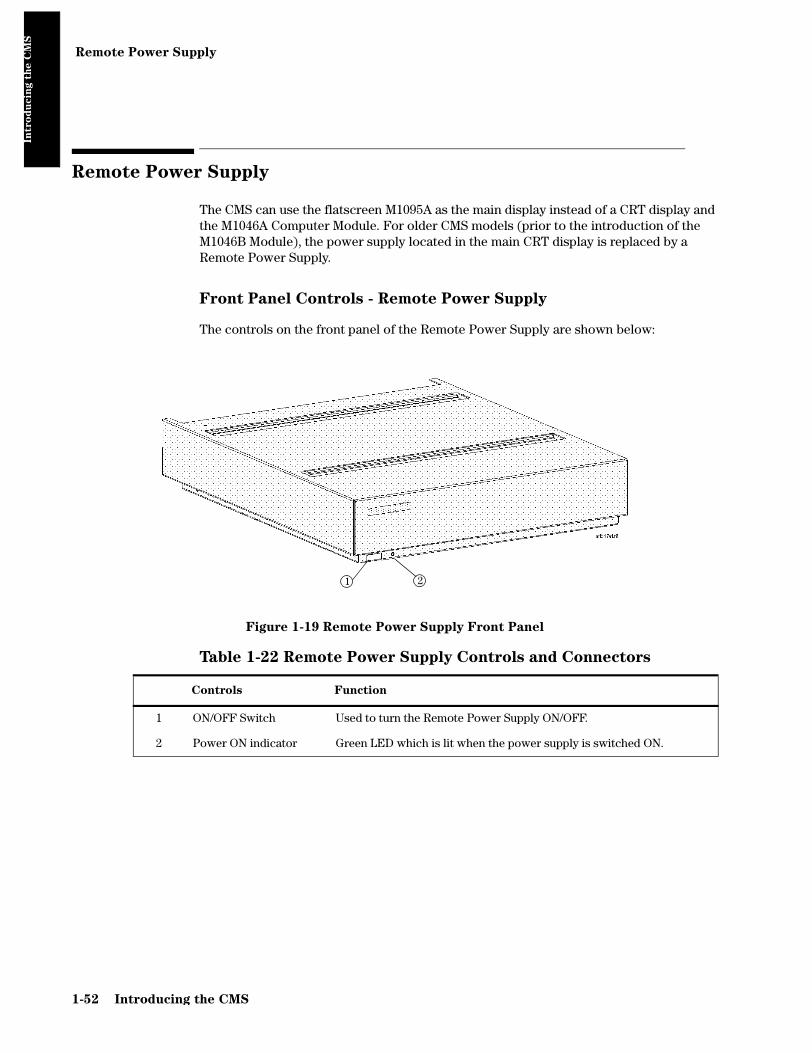
Remote Power Supply
Intro
du
cin
g t
he C
MS
Remote Power Supply
The CMS can use the flatscreen M1095A as the main display instead of a CRT display and the M1046A Computer Module. For older CMS models (prior to the introduction of the M1046B Module), the power supply located in the main CRT display is replaced by a Remote Power Supply.
Front Panel Controls - Remote Power Supply
The controls on the front panel of the Remote Power Supply are shown below:
Figure 1-19 Remote Power Supply Front Panel
Table 1-22 Remote Power Supply Controls and Connectors
Controls Function
1 ON/OFF Switch Used to turn the Remote Power Supply ON/OFF.
2 Power ON indicator Green LED which is lit when the power supply is switched ON.
1 2
1-52 Introducing the CMS

Remote Power Supply
Intro
du
cin
g t
he C
MS
Remote Power Supply - Rear Controls and Connectors
The controls on the rear panel of the Remote Power Supply are shown below:
Figure 1-20 Remote Power Supply Rear Panel
Table 1-23 Remote Power Supply Rear Panel Controls and Connectors
Controls and Connectors Function
1 Remote ON/OFF Input This cable connects the Power Supply to the video interface board (located in the CMS Computer Module). It is a female “modular jack” connector with 6-pins, used to input the power supply output ON/OFF signal from the Flatscreen Display.
2 60 V DC (120W max) Output This is a female 15-pin Sub-D-Type connector, used to output the 60 V dc line voltage to the Computer Module.
3 Fuse Holders Two fuse holders for the line protection fuses.
4 Local Power Connector This is a 3-pin connector, used to input the local line voltage.
5 Equipotential Grounding Terminal This is a grounding stud connector, used to connect the system to an equipotential grounding system.
Introducing the CMS 1-53

Fuse Values
Intro
du
cin
g t
he C
MS
Fuse Values
All CRT Display Modules, main and slave, remote power supply and the integral power supply, contain system fuses. The fuse values for each are recorded on a label near the fuse holders. The following table gives the fuse values for the CRT Display Modules, the Remote Power Supply, and the integral power supply located in the M1046B Computer Module and refers you to the page number that contains an illustration showing the fuse positions.
Table 1-24 CMS Fuses
CRT Display Type / Power Supply Type
Line Voltage
100-120 V
Line Voltage
200-240 V Page
Location
Fuse RatingPart
NumberFuse Rating
Part Number
VDE UL
M1092A Mono CRT Display (Main / Slave) 2 x T4.0 A 2110-0365 2 x T2.0 A 242208625096FMI
242208601266FMI
1-12 / 1-15
M1094A Color CRT Display (Main / Slave) 2 x T4.0 A 2110-0365 2 x T2.5 A 242208610219FMI
242208610009FMI
1-12 / 1-15
M1094B Color CRT Display (Main / Slave) 2 x T4.0 A 2110-0365 2 x T3.15 A H 242208610239FMI 1-12 / 1-15
M1047A Remote Power Supply 2 x T4.0 A 2110-0365 2 x T3.15 A H 242208610239FMI 1-53
M1046B Integral Power Supply 2 x T3.15 A H 2110-1025 2 x T3.15 A H 242208610239FMI 1-51
1-54 Introducing the CMS

Plug-in Module Racks
Intro
du
cin
g t
he C
MS
Plug-in Module Racks
The Plug-in Module Rack of the CMS is the interface between the Plug-in Modules and the Computer Module. The racks can be either integral, located in the M1046A Computer Module or satellite, located in the patient vicinity connected by a cable to the rack interface of the Computer Module (M1046A or M1046B). Satellite Racks can also be daisy-chained, depending on how many modules your system can support. Three plug-in module racks are currently supported by the monitor: 8-slot integral rack, M1043A, 8-slot Satellite Rack M1041A and 6-slot rack of the Philips Component Transport System, M1276A.
A blank rack is also available for the M1046A Computer Module. The blank rack is used if you do not require plug-in modules to be placed close to the Computer Module. The blank rack acts as the connection between the Satellite Rack and the Computer Module.
Objective
In order to meet this section’s goals, you should be able to:
• Identify the connectors of the plug-in module racks.
• Be familiar with the function of the plug-in module racks.
Concepts
The plug-in module racks of CMS are not fitted with any controls, just connectors. The function of the rack is to connect the plug-in modules to the Computer Module. A standard CMS integral rack contains eight slots for plug-in modules. Modules can be single-width modules or double-width modules so the number per rack depends on which plug-in modules are being used. To accommodate more modules, you can daisy-chain Satellite Racks to the rack in the Computer Module. The number of monitoring slots supported depends on the model of your monitor.
Integral Rack The integral rack is a plastic rack that sits in the front of the M1046A Computer Module and connects the plug-in modules to the system. It contains a rack interface connector, a defibrillator connector, module connectors and a rear internal rack connector.
Satellite Rack The Satellite Rack is a plastic rack that is remote to the Computer Module and connects plug-in modules to the system. It connects by a cable to a rack interface connector to route the data between the plug-in modules and the Computer Module. It contains input and output rack interface connectors and module connectors, but it does not have a defibrillator connector.
Blank Rack The blank rack is a plastic rack that sits in the front of the M1046A Computer Module and provides connections for a defibrillator and
Introducing the CMS 1-55

Plug-in Module Racks
Intro
du
cin
g t
he C
MS
Satellite Racks to the system. It is used if you do not require plug-in modules to be placed close to the M1046A Computer Module.
Front and Rear Connectors
Figure 1-21 Integral Plug-in Module Rack M1043A
Table 1-25 Plug-in Module Rack Connectors
Connector Function
1 Rack Interface Connector
Female interface connector, used to daisy-chain Satellite Racks.
2 Defibrillator Connector
0.25" phone socket, used to output an ECG wave to synchronize a defibrillator and provide an input for the defibrillator marker signal. It is also used as an output of ECG waveforms during the specification tests. See Parts List for ECG-Sync Cables.
3 Module Connectors Female plug-in module connectors, used to input the information from the plug-in modules to the integral rack.
4 Internal Rack Connector
Rack Interface connector (located on rear of the integral rack or blank rack), used to output the information from the rack to the Rack Interface function card placed in slot 18 of the Computer Module.
DefibrillatorConnector
(2)
Connector(1)
ModuleConnectors
(3)
mar3a
Internal Rack Connector (Rear)(4)
Rack Interface
1-56 Introducing the CMS

Plug-in Module Racks
Intro
du
cin
g t
he C
MS
Figure 1-22 Satellite Plug-in Module Rack M1041A with Parameter Modules
Table 1-26 Plug-in Module Rack Connectors
Connector Function
5 Rack Input Connector
Male Rack Interface Connector, used to connect the Satellite Rack to the Computer Module or to the previous rack in the chain.
6 Rack Output Connector
Female Rack Interface Connector, used to connect the Satellite Rack to the next rack in the chain.
(5.5")
138mm
(3.7")93mm
418mm(16.5")
Rack Input Connector (Rear)(5)
Rack Output Connector (Rear)(6)
Introducing the CMS 1-57

Plug-in Modules
Intro
du
cin
g t
he C
MS
Plug-in Modules
The plug-in parameter modules of the CMS can be thought of as the specialists of the monitor. Each module carries out a specific task and can be moved from one monitor to another, depending upon the functionality of the respective monitors. Plug-in modules are labeled with a symbol or the name of the measurement that they perform.
Objective
In order to meet this section’s goals, you should be able to:
• Identify the controls found on the front of plug-in modules.
• Be familiar with the function of the controls of the plug-in modules.
• Identify the connectors found on the front and rear of plug-in modules.
Concepts
The plug-in modules of CMS have one or more hardkeys on the front panel. The hardkey labeled with the parameter name is the setup key, which lights up the setup indicator and gets you directly into the Task Window for that parameter.
The connector socket on the front of each module varies, but it is the same color as the corresponding connector plug on the transducer or patient cable for that module. The connector on the rear panel of each plug-in module is a male connector, used to supply power and allow communication from the module to the module rack.
Plug-in modules can be either single-width or double-width units. A single-width module will occupy one slot in a module rack while a double-width module will require two-slots. Therefore, you must consider the width of the plug-in modules and number of slots that you have available to determine how many modules you can use in a single monitor. See Appendix A Product Information for more module information.
Parameter The parameter of the plug-in module is the specific clinical measurement performed by the module. Some modules, like the ECG/Resp module, are capable of monitoring more than one parameter.
Single-width
Module
A module that occupies only one slot in the module rack.
Double-width
Module
A module that occupies two slots in the module rack.
1-58 Introducing the CMS

Plug-in Modules
Intro
du
cin
g t
he C
MS
Plug-In Module Control Panel Keys and Indicators
The following drawings represent the types of controls, indicators and connectors found on the front panels of the plug-in modules. The controls, indicators and connections are described in the following table.
Figure 1-23 Examples of the Plug-in Module Front Panels
NBP STAT START STOP
M1008BNBP T(7)
(4)
(5)
(3)
(15)
(2)
(1)
(6)
M1002A
12PIN
ECG/RESP
ECG
T
RESP
(2)
(1)
(2)
(1)
(16)
M1016A
12PIN
CO
CO
T
CAL2
2
(2)
(1)
(16)
(9)
(8)
M1006B
12PIN
PRESS
PRESS
T
ZERO
(2)
(1) (10)
(16)
M1029A
2PIN
TEMP
TEMP
T
(17)
RUN/
STOP
REC M1116B
CONT
(11)
(12)
(13)
CAUTION: OUTPUT HASOFFSET ON 6 AND 10 SCALE
PRESS OUT PRESS ZERO
CAUTION:5uv/V/mm HgTRANSDUCERSONLY
PRESS M1006A T
(1)(18)
(16)
80x100(2)
M1032AVueLink T
(2)
(1)
(16)
VueLink
AUXILIARY A
(14)
CAL
tcpO /tcpCOM1018A
T
(20)(19)
(2)
2 2
O2/CO2
Introducing the CMS 1-59

Plug-in Modules
Intro
du
cin
g t
he C
MS
Table 1-27 Plug-in Module Controls and Connectors
General Controls Function
1 Setup Key Used to enter the module setup screen or Task Window.
2 Setup Indicator Green LED lit when in the module setup screen.
3 Start Key Used to start a measurement cycle.
4 Start Indicator Green LED which will be lit when the measurement cycle is entered.
5 Stop Key Used to stop the measurement cycle.
6 Stat Key Used to start a Static measurement cycle.
7 Stat Indicator Green LED lit when the static measurement cycle is entered.
8 CAL Key Used to enter the module's calibration screen and initiate module calibration procedures.
9 CAL Indicator Green LED lit during a module calibration procedure.
10 Zero Key Used to zero a transducer without using the main display controls.
11 Continue LED Lights if the current recording is continuous. The LED also blinks twice when the module is first plugged in. This indicates that the recorder self-test has been completed successfully.
12 RUN/CONT Key Used to start a Mode A continuous real-time recording, if the recorder is not running. If the recorder is running, it makes the current recording continuous (if possible).
13 STOP Key Stops the current recording.
14 Labels Labels giving names of the external devices to which the VueLink module can be connected and an LED beside each label, indicating the selected device.
15 NBP Connector Standard NBP connector for connection to the cuff.
16 12-pin Connector Standard 12-pin connector for use with Transducers. Refer to the tables on page 1-63.
17 2-pin Connector Standard 2-pin connector for use with standard series temperature probes.
18 Analog Output Jack Standard 1/4 inch phone jack used to provide analog signals to an intra-aortic balloon pump on the M1006A Option #C01. The M1006B Option #C01 has 3.5mm phone jack socket, supplied with adapter for those customers who have been using a 6.3mm (1/4 inch) phone jack.
19 Calibration Chamber Calibration chamber, with gas inlet for tcpO2/tcpCO2 module.
20 20-pin Connector 20-pin connector for use with a tcpO2/tcpCO2 transducer.
1-60 Introducing the CMS

Plug-in Modules
Intro
du
cin
g t
he C
MS
The following is the front panel of the SideStream CO2 module.
Figure 1-24 Sidestream CO2 Module Controls and Connectors
Table 1-28 Sidestream CO2 Module
Connector Function
1 Gas Outlet Connector Lets out the gas after it has been sampled.
2 Gas Inlet Connector Provides the connection for the sample tubing (and bacterial filter) which receives the patient's gas sample.
3 Slide Cover Protects the gas inlet connector when the module is not in use.
4 Sample Cell The CO2 transducer is mounted on the sample cell of the sidestream module. The transducer plug is connected to the M1016A CO2 Plug-in Module.
5 Switch Activates the sidestream pump when the CO2 transducer is mounted on the sample cell.
6 Mounting Clamp Holds the CO2 transducer in place.
(1)
(5)
(2) (3)
(4)
(6)
M1015A
Introducing the CMS 1-61

Plug-in Modules
Intro
du
cin
g t
he C
MS
The following are the front and rear panels of the Blood Analysis Module:
Figure 1-25 Blood Analysis Module
Table 1-29 Blood Analysis Module Controls and Connectors
Control/Connector Function
1 Setup Key Used to enter the Blood Analysis Setup or Results screen.
2 Setup Indicator Green LED lit when in Blood Analysis screens.
3 Cartridge Locked Indicator Green LED blinks when a cartridge is being processed; the cartridge must be left in the slot until the blinking stops and the light is off.
4 Cartridge Insertion Slot The cartridge is inserted here for processing.
5 Identification Label Contains product serial number and identification details.
6 Software Update Link Connector For connecting to the Central Data Station (or other PC) to perform software upgrades. During the upgrade process, the module is powered via this link.
7 Parameter Module Connector Connects the module to the rack.
(3)
(4)
(1)
(2)
(7)
(6)
(5)
1-62 Introducing the CMS

Plug-in Modules
Intro
du
cin
g t
he C
MS
Plug-in Module Pin-outs
There are several types of connectors found on the front of the plug-in modules. The following tables give the pin-out information for the plug-in modules that contain front panel connectors.
Table 1-30 Parameter Module Connector Signals
Pin
#
Parameter Module
ECG
M1001A/B
ECG/Resp
M1002A/B
Pressure
M1006A/B
C.O.
M1012A
CO2
M1016A
FIO2
M1017A
SpO2/Pleth
M1020A
EEG
M1027A
1 right arm right arm + resp Shield (M1006B)
- detector signal
- signal (photocurrent)
EEG1–
2 right leg right leg - GND detector bias
- GND + shield REF
3 - - - injectate temp
heater return
- resistor code 1 -
4 - - - GND drive coil - LED com -
5 chest chest jumper to 8 blood temp
sense coil - resistor code 2 EEG1+
6 left leg left leg + resp - code resistor
GND - LED com EEG2–
7 left arm left arm - GND IR-source - LED 12 EEG2+
8 - - jumper to 5 - heater power
- LED 34 -
A - - – excitation start key (to C)
GND feedback resistor
GND -
B - - + input - GND input current
- -
C shield shield + excitation start key temp. sense high
polarizationvoltage
- shield
D - - + input - temp. sense low
- - shorted to C
Introducing the CMS 1-63
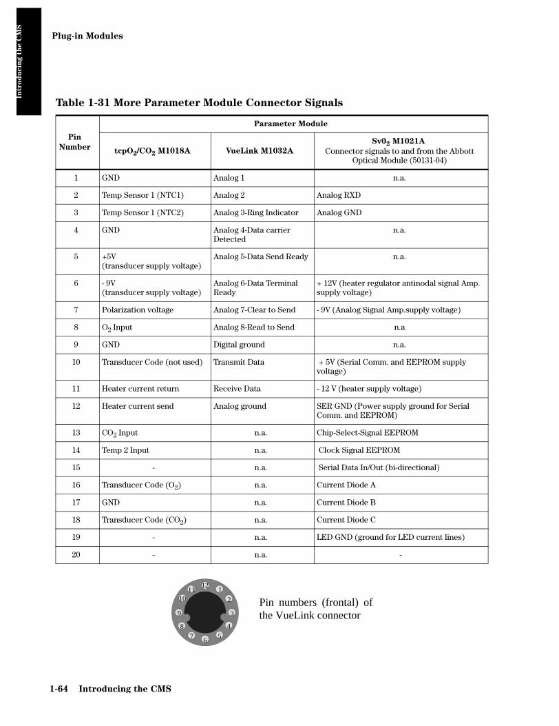
Plug-in Modules
Intro
du
cin
g t
he C
MS
Table 1-31 More Parameter Module Connector Signals
Pin
Number
Parameter Module
tcpO2/CO2 M1018A VueLink M1032A
Sv02 M1021A
Connector signals to and from the Abbott Optical Module (50131-04)
1 GND Analog 1 n.a.
2 Temp Sensor 1 (NTC1) Analog 2 Analog RXD
3 Temp Sensor 1 (NTC2) Analog 3-Ring Indicator Analog GND
4 GND Analog 4-Data carrier Detected
n.a.
5 +5V (transducer supply voltage)
Analog 5-Data Send Ready n.a.
6 - 9V (transducer supply voltage)
Analog 6-Data Terminal Ready
+ 12V (heater regulator antinodal signal Amp. supply voltage)
7 Polarization voltage Analog 7-Clear to Send - 9V (Analog Signal Amp.supply voltage)
8 O2 Input Analog 8-Read to Send n.a
9 GND Digital ground n.a.
10 Transducer Code (not used) Transmit Data + 5V (Serial Comm. and EEPROM supply voltage)
11 Heater current return Receive Data - 12 V (heater supply voltage)
12 Heater current send Analog ground SER GND (Power supply ground for Serial Comm. and EEPROM)
13 CO2 Input n.a. Chip-Select-Signal EEPROM
14 Temp 2 Input n.a. Clock Signal EEPROM
15 - n.a. Serial Data In/Out (bi-directional)
16 Transducer Code (O2) n.a. Current Diode A
17 GND n.a. Current Diode B
18 Transducer Code (CO2) n.a. Current Diode C
19 - n.a. LED GND (ground for LED current lines)
20 - n.a. -
Pin numbers (frontal) ofthe VueLink connector
1
2
3
45
67
8
9
1011
12
1-64 Introducing the CMS

Operating Modes
Intro
du
cin
g t
he C
MS
Operating Modes
There are four operating modes for the CMS: Monitoring, Service, Demo, and Configuration Mode. The only mode that supports monitoring is the Monitoring Mode. All modes are entered through passwords to prevent unintentional mode changes. From Rel. C.0 returning to monitoring mode is allowed without entering a password.
Objective
In order to meet this section’s goals, you should be able to:
• Identify the monitoring modes of CMS.
• Be familiar with the function of the monitoring modes of CMS.
Concepts
The operating modes of CMS are designed for specific tasks.
• Monitoring Mode is the standard operating mode that supports patient monitoring.
• Service Mode is used to perform service functions.
• Demo Mode is used to demonstrate the functions of the system.
• Configuration Mode is used to modify the behavior of the system.
Monitoring Mode is the only mode that should be used on a monitor that is attached to a patient. To ensure that the operating mode is not changed by unauthorized personnel, passwords are required to change operating modes.
When you change the operating mode of the monitor, you reset the patient database and all temporary changes that you have made to the system. This is why the system will always display a warning message “Patient data cleared - Settings reset” and ask you to confirm the action before it changes operating modes.
Main Screen This screen shows the waveforms and numerical readouts of the parameters you have chosen to monitor: alarms, INOP messages, bed label, date and time, and arrhythmia messages (when assigned).
Selection
Window
The Selection Window is the first operating level where you can choose a specific activity or function. It is entered through a hardkey on the Control Panel or the Handheld Keypad.
Task Window The Task Window is the second operating level which allows you to make changes or adjustments to the parameters and screen displays, or to perform procedures. It is entered through a softkey in the Selection Window or directly through the Control Panel of the plug-in module.
Introducing the CMS 1-65

Operating Modes
Intro
du
cin
g t
he C
MS
Status Message The status message is a string of text displayed in the top center of the screen below the date and time. A message is displayed in status line to indicate the current operating mode if not Monitoring.
Operating Rules to Remember
• Pressing the or hardkey always returns you to the main screen.
• To get into a Selection Window press a hardkey.
• Active softkeys are highlighted and/or look like “pushed-in” buttons (3-D effect).
• Softkeys only function in the Selection and Task Windows.
• The parameter module setup key gets you directly into a Task Window.
• The arrow keys and Confirm key are always illuminated when available for use.
• If after pressing a setup key the LED is not lit, the system is busy and the setup screen cannot be entered. The setup key must be pressed again. If you continue to have problems see the troubleshooting chapter.
• When an operating mode is entered or left, all monitoring settings are reset to the user defaults and the database is cleared.
Identifying Monitoring Mode
Monitoring Mode is the standard mode and is used when the monitor is attached to a patient. No other mode should be used when a patient is connected to a monitor. In this mode you will have access to three types of screens: the Main Screen, the Selection Windows and Task Windows. Through these screens you can make temporary changes to customize the parameter settings and the monitor setup as well as perform all of the monitoring tasks of CMS.
When you are in monitoring mode, you will see active messages on the screen indicating the status of the patient and the monitor. INOP messages are displayed in the upper left-hand corner of the display and alarm message in the upper right. When the monitor is in any mode other than Monitoring Mode, you will find a text message in the status line that indicates the active mode.
Identifying Demo Mode
Demo Mode is the mode used to demonstrate the monitoring functions of the system. It provides the user with sample waves and screens but it does not support monitoring and should not be used when a patient is attached to the monitor. All three levels of monitoring screens are available in Demo Mode: Main Screen, Selection Window and Task Window. Demo Mode demonstrates the modules that are currently plugged into the monitor so don’t expect to see waves for modules that are not in the rack.
Main Screen Standard Display
The Demo Mode
does not support
patient monitoring
and should never be
active while a
patient is attached
to the monitor.
1-66 Introducing the CMS

Operating Modes
Intro
du
cin
g t
he C
MS
To clearly identify the Demo mode, a text message is displayed in the status prompt. The message reads “DEMO Mode Active - NO MONITORING”. If your monitor is running Release E or later, the message “DEMO” is displayed in inverse low-intensity white characters in the first wave channel underneath the status prompt line. This message is alternatively displayed to two lines of normal characters in the same inverse block telling the user “to exit: press CONFIRM”. To leave Demo Mode in systems running Release D or earlier, you must use the standard procedure of using a password to change the operating mode. Either way, leaving Demo Mode or any other mode causes the patient data to be cleared and the settings to be reset.
Identifying Configuration Mode
The Configuration Mode is the operating mode used to change the monitoring behavior and screen layout. This mode is used to customize the monitor to meet your hospital’s monitoring protocols. When you make changes in the Config Mode, you are creating permanent user settings to replace the standard factory settings that came with the monitor. A cold start or operating mode change will clear the patient data and reset any temporary changes you made in Monitoring Mode to the permanent user settings you made in Config Mode.
To clearly identify the Config Mode, a text message is displayed in the status prompt. The message reads “Config Mode Active - NO MONITORING”. No waveforms, INOPS or alarms are displayed in Config Mode. Like the other operating modes, you must input a password to enter and exit the Config Mode.
Identifying Service Mode
The service mode is the operating mode used by service personnel to access complete error message listings and perform service related tasks, like specification tests. The Service Mode is also used to troubleshoot the monitor.
To clearly identify the Service Mode, a text message is displayed in the status prompt. The message reads “Service Mode Active - NO MONITORING”. No waveforms, INOPS or alarms are displayed in Service Mode. Like the other operating modes, you must input a password to enter and exit the Service Mode.
The Config Mode
does not support
patient monitoring
and should never be
active while a
patient is attached
to the monitor.
The Service Mode
does not support
patient monitoring
and should never be
active while a
patient is attached
to the monitor.
Introducing the CMS 1-67

Operating Modes
Intro
du
cin
g t
he C
MS
Changing Operating Modes
Now that you know about the various operating modes of CMS, let’s look at how to move between two operating modes. This requires operating mode-specific passwords. Mode-specific passwords guard against unauthorized changes to the monitor.
The operating modes of CMS can be changed using the following sequence of keys and passwords.
Note: From Rel. C.0, returning to monitoring mode is allowed without entering a password. Just press followed by .
Table 1-32 Procedure to Change Operating Mode
Step Action Comment
1 Press (or ) The monitor setup or instrument configuration Selection Window is displayed.
2 Press if available Shows additional choices for softkeys in this Selection Window.
3 Press softkey The Operating Mode Task Window displays the current operating mode in words (for example, “Operating Mode - Monitoring”) and prompts for the password.
4 Enter the password. Configuration Mode: 1245Demo Mode: 14432a
Service Mode: 4311Master Password: 14432a
a. Note: Use of this password allows access to all operating modes
Use the keys labeled 1 to 5. If the password is correct, then the Change OpMode softkey is highlighted. If the password is incorrect, the system returns to the Standard Display.
5 Press softkey The Operating Mode Task Window displays both Monitor and Config in reverse video, with the current operating mode highlighted.
6 Select the required Operating Mode. Use the arrow keys or press the Change Opmode softkey.
7 Press . The system performs a cold-start and switches operating modes.
Monitor Setup Resume Monitor
Monitor Setup Instrument Config
More Choices
Operating Modes
Change OpMode
Confirm
1-68 Introducing the CMS

Chapter 2 Testing & Maintaining the CMS
Testin
g &
Main
tain
ing
th
e C
MS
The first section in this chapter describes the procedures required to ensure that the CMS is in safe working order. The following sections describe recommended procedures for maintaining the equipment. These procedures apply to all versions of the CMS. The procedures are grouped as follows:
Mandatory Periodic Maintenance and Safety Checks
• Performance and Safety Test requirements
• Preventive Maintenance Procedure for the CMS Wall Mount Assembly
Recommended Maintenance Procedures
• General Inspections of the System
• Cleaning and Disinfecting Procedures for the CMS
See “Procedure Overview” on page 2-2 for a more detailed overview.
Objectives
In order to meet the chapter’s goals, you should be able to:
• Perform required safety checks and maintenance procedures.
• Perform a general inspection of the system.
• Clean the major units of the CMS.
Concepts
The Philips CMS Patient Monitoring System has different levels of preventive maintenance and checks that should be performed on a periodic basis or as recommended.
If you wish to perform more detailed tests on the plug-in parameter modules, please see Chapter 4 “Troubleshooting the Plug-in Modules”.
The procedures described in this chapter should be performed at the specified time intervals to ensure effective preventive maintenance. The checklist may be photocopied, completed by the maintainer, and filed for reference.
Testing & Maintaining the CMS 2-1

Procedure Overview
Testin
g &
Main
tain
ing
th
e C
MS
Procedure Overview
Table 2-1 Mandatory Periodic Maintenance and Safety Checks
Procedure Steps Page
“Test and Inspection Requirements” When to Perform Test BlocksTests and Inspection RequirementsSafety TestsSafety Test Diagrams
2-32-52-112-12
“Preventive Maintenance Procedure for the Philips M1180A #A01 and #A02 Wall Mount Assembly”
Step 1: Inspect visible fastenersStep 2: Check maximum tilt rangeStep 3: Inspect mounting plate for movement
2-152-172-17
Table 2-2 Recommended Maintenance Procedures
Procedure Steps Page
“General Inspections of the System” Inspect the System HardwareInspect the CablesInspect the Red Power Indicators (LEDs) of the System Inspect the Display CRT / LCDInspect the Controls of the System
2-192-202-202-212-22
“Cleaning and Disinfecting Procedures” General Cleaning of the SystemGeneral Disinfecting of the SystemCleaning the Recorder ModuleCleaning the Blood Analysis Module
2-242-252-262-27
2-2 Testing & Maintaining the CMS

Test and Inspection Requirements
Testin
g &
Main
tain
ing
th
e C
MS
Test and Inspection Requirements
NOTE The Test and Inspections Procedures described in this section are mandatory requirements.
This section is intended primarily for Philips customer engineers and lists the mandatory test requirements for CMS for servicing, installation and preventive maintenance. For some tests it is required that the Philips engineer documents the results in a service record.
Table 2-3 When to Perform Test Blocks explains when to perform the procedures. Table 2-4 Tests and Inspection Requirements explains the procedures to be performed.Table 2-5 CMS Test and Inspection Requirements – Safety and Table 2-6 Safety Test Diagrams give full details of the Safety Tests.
NOTE Note: Only Philips service engineers are required to report the results of the following safety and performance tests back to the factory. Of the performance tests, only those for NBP and Sidestream CO2 need to be reported. .
Table 2-3 When to Perform Test Blocks
Service Event
– When performing
Test Block(s) Required
Complete these tests
Installation of CMS with Medical equipment connections (for example, AGM or Vuelink) but with NO System (SDN)
Perform Visual and Power On test blocks (see page 2-5).
Installation of CMS that is connected to a System (SDN)
Perform Visual and Power On test blocks. If the 78581A safety test (see the 78581A service manual) has passed previously no further safety tests are required. If the 78581A safety test has not been performed, it must be completed.
Testing & Maintaining the CMS 2-3

Test and Inspection Requirements
Testin
g &
Main
tain
ing
th
e C
MS
Installation of CMS that has connections to non-medical devices (for example, XGA Display, Laser Printer or PC)
Note:
If a non-medical device requires the use of an isolation transformer in order to limit the enclosure leakage current to meet the requirements of IEC 601-1, the power cable connecting the non-medical device to the isolation transformer must be fixed. It must not be possible to remove the power cable without the use of appropriate tools.
Note:
If a non-medical device requires the use of additional protective earthing in order to limit the enclosure leakage current to meet the requirements of IEC 601-1, the earthing components must be securely fixed at both ends and must not be removable without the use of appropriate tools.
Note:
Interface cables over 3.om are not to be used.
Device type and
test required
Test results (where
appropriate)
Action required
Device is NOT IEC 601-1, IEC 60950 or IEC 61010 compliant
Not applicable Device NOT acceptable.
DO NOT USE
Device is IEC 601-1 compliant
No tests required Device acceptable. No action required.
Device is IEC 60950 or IEC 61010 compliant
Class I Equipment (Protectively Earthed Equipment)
Perform Visual and Power On test blocks (see page 5). Perform Safety (1) test block (see page 11).
Compliant with IEC 601-1 Enclosure Leakage Current limitations
Device acceptable. No action required.
Normal condition is within the requirements of IEC 601-1
Single fault condition exceeds IEC 601-1 requirements
Additional Protective Earthing must be provided for non-medical device, and must not be removable without the use of a appropriate tools
or
Non-medical device must be connected to the mains supply via an Isolation Transformer
Normal condition exceeds IEC 601-1 requirements
Non-medical device must be connected to the mains supply via an Isolation Transformer
Device is IEC 60950 or IEC 61010 compliant
Class II equipment (Double Insulated Equipment)
Perform Visual and Power On test blocks (see page 11). Perform Safety (1) test block (see page 11).
Normal condition exceeds IEC 601-1 requirements
Non-medical device must be connected to the mains supply via an Isolation Transformer
or
Non-medical device must isolated from the medical device by use of a separation device
Repairs where the power supply in the M1094A/M1094B/M1092A/M1046B assembly is replaced
Perform Power On and Safety (2) test blocks (see page 2-11).
Repairs where the monitor has been dropped
Perform Power On and Safety (2) and (3) test blocks (see page 2-12).
All other CMS repairs, Hardware or Software Upgrades
Perform Power On test block.
Table 2-3 When to Perform Test Blocks
Service Event
– When performing
Test Block(s) Required
Complete these tests
2-4 Testing & Maintaining the CMS

Test and Inspection Requirements
Testin
g &
Main
tain
ing
th
e C
MS
Preventive Maintenancea Perform the NBP and Sidestream CO2 Module Performance test blocks every year (see page 2-6).Perform the Preventive Maintenance Procedure for the M1180A #A01/A02 Wall Mount Assembly every year (see page 2-15).If an AGM is present, refer to the AGM (M1026A) test matrix.For the BIS module no periodic preventive maintenance is required.
Performance Assurance and Safety Testsb Perform all other Performance test blocks and all Safety test blocks (1), (2) and (3) once every two years.
a. For Germany only: For modules that do not have the CE mark, contact the Customer Response Center in Ratingen for information.
b. For the BIS module performance and safety testing is optional (Philips recommends yearly test-ing). However, safety testing (Safety test block (3)) is required if there is suspected liquid ingress or after every time the case of any of the BIS components has been opened.
Table 2-4 Tests and Inspection Requirements
Test Block
NameTest or “Inspection” to Perform Expected Test Results
What to
Record on
Service
Record
Visual Test Inspect the system for obvious signs of damage. Also check external leads and accessories.
The system does not have any obvious signs of damage = Pass.
V:P or V:Fwhere P = Passand F = Fail
Visual Test for M1180A #A01/A02
Step 1: Inspect visible fastenersStep 2: Check maximum tilt rangeStep 3: Inspect mounting plate for movement
Mounting is within Specs as described on page 2-15 and following.
VM:P or VM:Fwhere P = Passand F = Fail
Power On Test Monitor boots up.All Alarm LEDs light up shortly.From release B.0, the loudspeaker gives a series of test sounds.No error codes are displayed.An ECG wave is displayed.
PO:P or PO:F where P = Passand F = Fail
Table 2-3 When to Perform Test Blocks
Service Event
– When performing
Test Block(s) Required
Complete these tests
Step Step
1 Switch on the monitor.
2 Plug in an ECG Module.
3 Observe whether the monitor boots up successfully without displaying an error code and if an ECG wave appears on the display.
Testing & Maintaining the CMS 2-5

Test and Inspection Requirements
Testin
g &
Main
tain
ing
th
e C
MS
Performance Test NBP Module
Accuracy TestValue displayed on Monitor = x1
If difference (<= 3mm)
Proceed to next test.
Performance Test NBP Module (contd.)
Leakage TestLeakage test value = x2(<= 6 mmHg)
Proceed to next test.
Table 2-4 Tests and Inspection Requirements(Continued)
Test Block
NameTest or “Inspection” to Perform Expected Test Results
What to
Record on
Service
Record
Step Action
1 Connect the manometer and the pump with tubing and expansion chamber to the NBP connector on the NBP Module.
2 Go to Service Mode.
3 Press the NBP button on the NBP Module.
4 Press Start button in the task window to close valves.
5 Raise the pressure to 280 mmHg with the manometer pump.
6 Wait 10 sec for the measurement to stabilize.
7 Compare the manometer values with the displayed values.
8 Document the value displayed by the Monitor.If the difference is greater than 3 mmHg, calibrate the module.
Step Action
1 Press the NBP button on the Module.
2 Press the Start softkey in the task window.
3 Pressurize the gauge to 280 mmHg.
4 Watch the pressure value for 60 seconds.After 60 seconds the value should have decreased by less than 6 mmHg.
5 Calculate and document: Leakage test = Accuracy – displayed value
2-6 Testing & Maintaining the CMS

Test and Inspection Requirements
Testin
g &
Main
tain
ing
th
e C
MS
Linearity TestValue displayed on Monitor = x3If difference (<= 3 mmHg)
Proceed to next test
Valve TestValue displayed on Monitor = x4(< 10 mmHg)
PN:P/x1/x2/x3/x4or PN:F/x1/x2/x3/x4where P = Passand F = Fail
Performance Test Sidestream CO2
Flow Adjustment ProcedureValue displayed on CMS = x1(where x1 = 100 +/– 10 ml/min)
Proceed to next test
Table 2-4 Tests and Inspection Requirements(Continued)
Test Block
NameTest or “Inspection” to Perform Expected Test Results
What to
Record on
Service
Record
Step Action
1 Reduce the manometer pressure down to 150 mmHg.
2 Wait 10 sec for the measurement to stabilize.
3 Compare the manometer values with the displayed values.
4 Document the value displayed by the Monitor.If the difference is greater than 3 mmHg then calibrate the module.
Step Action
1 Raise the pressure to 280 mmHg.
2 Press Stop on the module to open valves.
3 Wait 5 seconds then document the value.
Step Action
1 Enter the CO2 Sidestream Task Window by pressing Parameters followed by CO2 Sidestream.
2 Press Start Pump. The date and time of the last flow adjustment are displayed.
3 Start the Flow Adjustment procedure by connecting the flow meter and pressing Start Pump. After about 5 seconds, the flow in ml/min displays in the Task Window.
4 Use the Adjust Flow to adjust the value displayed in the Task Window to the value displayed by the external flow meter.
5 Write down the value displayed by the CMS (x1).
6 Press Confirm to store the readjusted flow rate value. After about 5 seconds, the message “Adjustment done” displays. The flow is automatically set to 100 ml/min.
7 If the displayed value is not 100 ml/min, repeat Steps 3 through 5.
Testing & Maintaining the CMS 2-7

Test and Inspection Requirements
Testin
g &
Main
tain
ing
th
e C
MS
Performance Test Sidestream CO2 (contd.)
Barometric Pressure Adjustment ProcedureDifference = x2 (<= 4 mmHg)
PSC:P/x1/x2or PSC:F/x1/x2where P = Passand F = Fail
Performance Test ECG
Step 1 Connect the patient simulator to the ECG Parameter Module using the Patient cable.
Step 2 Configure the Patient simulator as follows:ECG sinus rhythmHR = 120 BPM (Amplitude 1 mV)
Step 3 Check displayed ECG wave and HR value against the simulator configuration. HR = 120 +/– 2 BPM
These results do not have to be reported.
Performance Test Respiration
Step 1 Connect the patient simulator to the ECG/Resp Module using the patient cable.
Step 2 Configure the patient simulator as follows:Base impedance line 1500 OhmDelta impedance 0.5 OhmRespiration Rate 40/min
Step 3 Check displayed respiration rate against the simulator configuration. RPM = 40 +/– 2 /min
These results do not have to be reported.
Performance Test Cardiac Output
Step 1 Connect the patient simulator to the C.O. Module using the patient cable.
Step 2 Configure the Patient simulator as follows:Injection temperature: 2 °C Computation Const: 0.542 (Edward's Catheter)Flow 5 l/min
Step 3 Check displayed value against the simulator configuration. C.O. = 5 +/– 1 l/min.
These results do not have to be reported.
Table 2-4 Tests and Inspection Requirements(Continued)
Test Block
NameTest or “Inspection” to Perform Expected Test Results
What to
Record on
Service
Record
Step Action
1 Press Barometer Pressure to adjust the Barometric Pressure value. The Task Window displays the stored barometric pressure in mmHg.
2 If the displayed value is incorrect, use the Barometer Pressure key to adjust the value to atmospheric pressure.
3 Document the Difference (x2) between the actual atmospheric pressure and the value displayed by the CMS.
4 Press Confirm to store the displayed or adjusted value. After about 5 seconds, the message “Adjustment done” displays. The barometric pressure is then set to the value you entered.
5 Press Main Screen (or Standard Display) to return to the standard display in Service mode
2-8 Testing & Maintaining the CMS

Test and Inspection Requirements
Testin
g &
Main
tain
ing
th
e C
MS
Performance Test Cardiac Output (contd.)
Service Tool procedure, Version 1
Note: This procedure applies for Service Tool M1012-
14232C and/or C.O. modules without option C10 and/or
software revision B.0 and below.
Step 1 Make sure to be in Monitoring Mode.Connect C.O. Interface Cable to module.
Step 2 Connect one side of the Service Tool to Injectate receptacle of C.O. Interface Cable and the other side to Catheter Cable receptacle.
Step 3 Enter Measure C.O. Task Window and check results. Tblood = 37.0oC +/- 0.1oCTinj = 0.0oC +/- 0.1oC
These results do not have to be reported.
Performance Test Cardiac Output (contd.)
Service Tool procedure, Version 2
Note: This procedure only applies for Service Tool M1012-
61601 in combination with C.O. modules with option C10
and software revision C.0 and greater.
Step 1 Make sure to be in Monitoring Mode.Connect C.O. Interface Cable to module.
Step 2 Connect one side of the Service Tool to Injectate receptacle of C.O. Interface Cable and the other side to Catheter Cable receptacle.
Step 3 Enter Setup C.O. Task Window and check results for:Method of MeasurementArterial Catheter Constant
Enter Measure C.O. Task Window and check results.Step 4 Disconnect Catheter Cable receptacle from Service
Tool.Step 5 Enter Module Setup Task Window.
Press Parameter On/Off.Press On/Off Setup to switch Setup On
Step 6 Enter Setup C.O Task Window and change method of measurement to “Right Heart”.
Step 7 Enter Measure C.O. Task Window and check results.
Transpulmonary341Tblood = 37.0oC +/- 0.1oC
Tinj = 0.0oC +/- 0.1oC
These results do not have to be reported.
Performance Test Invasive Pressure
Step 1 Connect the patient simulator to the Pressure module.
Step 2 Set patient simulator to 0 pressure.Step 3 Make a Zero Calibration with the module.Step 4 Configure the patient simulator for
P(static) = 200 mmHg. Step 5 Wait for the display. Step 6 Check displayed value against the simulator
configuration. If there is a difference, calibrate the module.
Note: If the Module was calibrated with a dedicated reusable
catheter, check the calibration together with this catheter.
P = 200 +/– 5 mmHg
These results do not have to be reported.
Performance Test Temperature
Step 1 Connect the patient simulator to the temperature input.
Step 2 Configure the patient simulator to 40 °C or alternatively 100 °F.
Step 3 Check displayed value against the simulator configuration.
+/– 0.2 °C or +/– 0.4 °F
These results do not have to be reported.
Table 2-4 Tests and Inspection Requirements(Continued)
Test Block
NameTest or “Inspection” to Perform Expected Test Results
What to
Record on
Service
Record
Testing & Maintaining the CMS 2-9

Test and Inspection Requirements
Testin
g &
Main
tain
ing
th
e C
MS
Performance Test SpO2
Step 1 Connect the sensor to the SpO2 module.Step 2 Measure the SpO2 value on your own finger (this
assumes that you are healthy).Step 3 Check displayed value against the simulator
configuration.Between 95 and 100%
These results do not have to be reported.
Performance Test ECG-Sync
This test is recommended for customer sites where ECG Sync is in use or is configured for potential use.Step 1 Connect the patient simulator to the ECG input and
the defibrillator to the CMS ECG-Sync output.Step 2 Configure the patient simulator as follows:
ECG sinus rhythmHR = 100 BPM (Amplitude 1 mV)
Step 3 Switch defibrillator to simulation mode.Step 4 Check that the marker pulse is displayed before the T-
Wave begins.Marker pulse is displayed before T-Wave begins.
These results do not have to be reported.
Performance Test Nurse Call Relay
This test is recommended for customer sites where the nurse call is in use.The Nurse Call Relay performance test is performed at the phone jack type connector.This test checks the operation of the Nurse Call Relay. The functionality of the Nurse Call depends on the configuration of the relay (see the CMS Configuration Guide).Tools required: OhmmeterStep 1 Plug a phono connector into the Nurse Call Relay
connector.Step 2 Connect the Ohmmeter.Step 3 Simulate an alarm-free and then an alarm condition.
While no alarm occurs, the relay contacts are open.When an alarm occurs, the relay contacts close
These results do not have to be reported.
Performance Test BIS
PIC/DSC Test
Step 1 In Monitoring mode connect the Sensor Simulator (for maximum usage please refer to the documentation delivered with the Sensor Simulator) to the Patient Interface Cable
Step 2 Enter the BIS Task Window by pressing Module Setup, followed by BIS.
Step 3 Start Impedance Check by pressing Start Check. This brings up the BIS Cyclic Check Task Window. Check the displayed results. Electrode 1: 4-6 kΩ
Electrode 2: 8-12 kΩElectrode 3: 1-3 kΩ
These results do not have to be reported.
Performance Test BIS (continued)
DSC Test
Step 1 Enter Service ModeStep 2 Enter the BIS Task Window by pressing Module
Setup, followed by BIS.Step 3 Start Test by pressing Test DSC. Check the displayed
results. Module: Test passedBIS engine: Test passedDSC: Test passed
These results do not have to be reported.
Table 2-4 Tests and Inspection Requirements(Continued)
Test Block
NameTest or “Inspection” to Perform Expected Test Results
What to
Record on
Service
Record
2-10 Testing & Maintaining the CMS

Test and Inspection Requirements
Testin
g &
Main
tain
ing
th
e C
MS
Safety Tests
For Europe and Asia-Pacific:
M1165A, M1166A, M1167A according to IEC 601-1:1988+A1+1991+A2:1995 = EN60601-1:1990+A1:1991+A2:1995
For the US:
M1175A, M1176A according to UL 544M1177A according to UL 2601-1
The test procedures outlined in this section are to be used only for verifying safe installation or service of the product in question.
The set-ups used for these tests and the acceptable ranges of values are derived from local and international standards but may not be equivalent.
These tests are not a substitute for local safety testing where it is required for an installation or a service event.
If using the Metron Safety tester, use your local regulation to perform the test, for
example, in Europe IEC601-1/IEC601-1-1, and in the U.S. UL2601-1. The Metron Report should print results with the names listed below, along with other data.
The Safety Tests required to ensure that the CMS is in safe working order are detailed in the following tables.
Table 2-5 CMS Test and Inspection Requirements – Safety
Test Block Name
Test or “Inspection” to Perform Expected Test Results
What to Record on Service Record
Safety (1): System Safety Test Enclosure Leakage Current /Normal Condition:
System Safety Test Enclosure Leakage Current / Single Fault Condition
Normal Condition maximum leakage current = x1. x1 <= 100 µAIEC601-1, UL2601-1 (UL544 test not required)
Single Fault maximum leakage current = x2.x2 is<= 500 µA (IEC601-1)or<= 300 µA (UL2601-1)or<= 100 µA (UL544)
S1:P/x1/x2 orS1:F/x1/x2where P = Passand F = Fail
Safety (2): Protective Earth With mains cable:Maximum impedance = x <= 100 mOhmsAll authorities (IEC601-1, UL2601-1, UL544)
S2:P/x or S2:F/xwhere P = Passand F = Fail
Testing & Maintaining the CMS 2-11

Test and Inspection Requirements
Testin
g &
Main
tain
ing
th
e C
MS
Safety (3): Patient Leakage Current AC Maximum leakage current= x<= 50 µA @ 250V (IEC601-1 or UL2601-1)or <= 10 µA @ 120V without patient leads connected (UL544)or<= 20 µA @ 120V with patient leads connected (UL544)
S3:P/x or S3:F/x
where P = Passand F = Fail
Table 2-6 Safety Test Diagrams
Test Block Name Test or Inspection to Perform
Safety(1) System Enclosure Leakage Current – NC (normal condition)
Measures leakage current of exposed metal parts of Instrument under Test (IUT) and between parts of the system within the patient environment; normal and reversed polarity using S2. Safety test according to IEC 601-1-1 (Clause 19.201.1). Report largest value.
Table 2-5 CMS Test and Inspection Requirements – Safety
Test Block Name
Test or “Inspection” to Perform Expected Test Results
What to Record on Service Record
(*) Not present in Class 2.(**) Can be multiple different connections to different equipment at same time.
PE
Instrument under test
Applied part(*)S4
N (L)
S1
S2
L (N)
Signal partsin- and/or output
MD
Medical electrical system
Signal partsin- and/or output
OtherInstrument
(**)
2-12 Testing & Maintaining the CMS
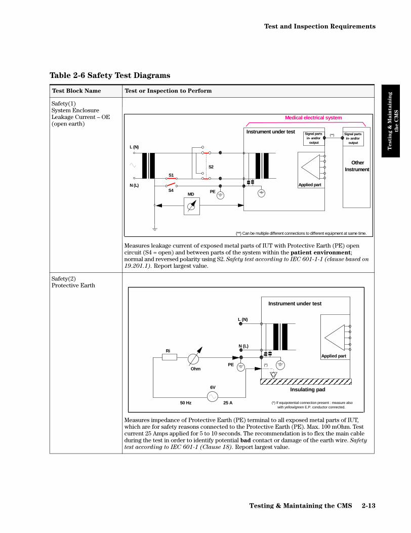
Test and Inspection Requirements
Testin
g &
Main
tain
ing
th
e C
MS
Safety(1) System Enclosure Leakage Current – OE (open earth)
Measures leakage current of exposed metal parts of IUT with Protective Earth (PE) open circuit (S4 = open) and between parts of the system within the patient environment; normal and reversed polarity using S2. Safety test according to IEC 601-1-1 (clause based on
19.201.1). Report largest value.
Safety(2) Protective Earth
Measures impedance of Protective Earth (PE) terminal to all exposed metal parts of IUT, which are for safety reasons connected to the Protective Earth (PE). Max. 100 mOhm. Test current 25 Amps applied for 5 to 10 seconds. The recommendation is to flex the main cable during the test in order to identify potential bad contact or damage of the earth wire. Safety
test according to IEC 601-1 (Clause 18). Report largest value.
Table 2-6 Safety Test Diagrams
Test Block Name Test or Inspection to Perform
(**) Can be multiple different connections to different equipment at same time.
PE
Instrument under test
Applied partS4
N (L)
S1
S2
L (N)
Signal partsin- and/or output
MD
Medical electrical system
Signal partsin- and/or output
OtherInstrument
(**)
50 Hz 25 A or 1.5 Ir
Ohm
L (N)
N (L)
PE
Instrument under test
Applied part
Insulating pad
Ri
6V
(*)
(*) If equipotential connection present : measure also with yellow/green E.P. conductor connected.
Testing & Maintaining the CMS 2-13

Test and Inspection Requirements
Testin
g &
Main
tain
ing
th
e C
MS
Safety(3) Patient Leakage Current – AC
Measures patient leakage current from Applied Part to earth caused by external main voltage on Applied Part with switch S5 open and closed. Each polarity combination possible is tested using S2 and S6. This test is applicable for every listed module (ECG, ECG/Resp, Invasive Pressure, Cardiac Output, CO2, SpO2, SvO2, FiO2, EEG, Temperature). Safety test according to IEC 601-1 (Clause 19.4.h). Report largest value.
Table 2-6 Safety Test Diagrams
Test Block Name Test or Inspection to Perform
Insulating pad
RS6
(*) Not present in Class 2
N (L)
Instrument under test
Applied partPE
S1S2
L (N)
S4 (*) Signal partin- and/or output
L (N)
N (L)
S5
MD
2-14 Testing & Maintaining the CMS
Preventive Maintenance Procedure for the Philips M1180A #A01 and #A02 Wall Mount Assembly
Testin
g &
Main
tain
ing
th
e C
MS
Preventive Maintenance Procedure for the Philips M1180A #A01 and
#A02 Wall Mount Assembly
Overview
The objective of this procedure is to inspect the mounting hardware for proper operation.
NOTE The Preventive Maintenance Procedure described in this section is a mandatory
requirement, which has to be performed once a year. All fasteners should be
checked and tightened or replaced as necessary.
The procedure consists of the following steps:
Step 1 Inspect all visible mounting-related fasteners
Step 2 Check maximum tilt range
Step 3 Inspect mounting plate for movement
Step 1: Inspect visible fasteners
Please refer to the diagrams on page 2-16 and 2-17 for mounting component identification.
1. Inspect gold and silver stabilizing clips viewable from the rear of the monitor. If a clip is missing, install new clips to ensure safety of the mount (See picture below). The Kit M1180-60504 contains the three clips and the necessary screws.
Testing & Maintaining the CMS 2-15

Preventive Maintenance Procedure for the Philips M1180A #A01 and #A02 Wall Mount Assembly
Testin
g &
Main
tain
ing
th
e C
MS
2. Refer to the diagram on page 2-16, inspect all visible fasteners and tighten as required. If a fastener is broken or missing, install new fasteners. The Kit M1180-60504 contains the three clips and the necessary screws.
Figure 2-7. Wall Mount Components Diagram
Gold Spring clip to locate Cam Handle
Silver Spring clips to stabilize rails and housing
Display Screen orComputer Module/ Integral Rack
M4 X 8mm PHMS (4) Adaptor Plate into Spanning Rail
Plunger Clearance Hole
Tilt / Swivel Head
Spring Plunger
M4 X 12mm PHMS (2) through mounting plate into tapped holes in adaptor plate
Diagonal BraceSlide with 1/4 - 20 X 3/4” Nylon Stop Screw
Wall Channel
M3 X 12mmPHMS - SS (4)
Adaptor Plate
Spring Clip042 - 10 (2)
Spanning Rail HPMR
M4 X 8mm PHMS (4) through tapped hole into square hole
Mounting Plate MP13P
15” Support Arm
2-16 Testing & Maintaining the CMS

Preventive Maintenance Procedure for the Philips M1180A #A01 and #A02 Wall Mount Assembly
Testin
g &
Main
tain
ing
th
e C
MS
Step 2: Check maximum tilt range
Please refer to the diagrams above and on page 2-17 for mounting component identification.
1. Rotate Tilt Knob counterclockwise until the knob stops. This is the maximum forward tilt angle. The maximum forward tilt range should not exceed 25° or 55mm (2.16”). (Refer to diagram below for reference angle). If the tilt range exceeds these specifications, the wall mount must be replaced.
Step 3: Inspect mounting plate for movement
1. With monitor set at desired tilt angle, apply pressure to the front of the monitor in an attempt to move it in a “rocking” motion. If the Mounting Plate “rocks”, or movement is observed between the mounting plate and tilt bar, the wall mount assembly must be replaced. Note: Minor “flexing” movement of the entire mounting assembly is normal.
2. If no “rocking” is detected, the mounting assembly is functioning properly, and the inspection procedure is complete.
Mounting PlateSupport Arm
25º Maximum Tilt
=55mm (2.16”)
Testing & Maintaining the CMS 2-17

Preventive Maintenance Procedure for the Philips M1180A #A01 and #A02 Wall Mount Assembly
Testin
g &
Main
tain
ing
th
e C
MS
Figure 2-8. Wall Mount Assembly Diagram
2-18 Testing & Maintaining the CMS
General Inspections of the System
Testin
g &
Main
tain
ing
th
e C
MS
General Inspections of the System
The CMS is designed to withstand the stresses of the Clinical Care environment. Each module of the system is encased in plastic and all of the cables and cords of the CMS are tested for patient safety. To keep your system in good physical condition, Philips recommends that you perform an annual inspection of the modules and cables of the CMS.
Objective
In order to meet the chapter’s goals, you should be able to perform a general inspection of the CMS.
Concepts
The CMS is composed of various modules: the Display Module, the Computer Module, the plug-in modules, the plug-in module rack, the Handheld Keypad, and, in certain configurations, the remote power supply (for the flatscreen display module) or the External Alarm Device (used with an XGA-compatible display). Each module contains connectors, controls or cables that should be checked annually to ensure that they are in good condition and functioning normally.
Since the CMS is used in situations where the modules may come in contact with human fluids, you should follow all of the procedures of your department for dealing with contaminated equipment before proceeding with any maintenance procedures.
Inspect the System Hardware
No tools are required to perform this inspection.
Step 1 Examine the exterior of the unit for cleanliness and general physical condition. Check that the plastic housings are intact, that all hardware is present and tight, and that there are no signs of spilled liquids or other serious abuse.
Step 2 Check fuse values and type against that marked on the chassis, and ensure that a spare is provided.
Step 3 Inspect connectors of the module rack and ensure that the plug-in modules are locked into place and do not slide out without first releasing the locking plate on the bottom of the module.
Step 4 Ensure all labeling is present and legible.
Step 5 Inspect all accessories external to the system such as transducers, referring to the manufacturer’s documentation.
Inspecting the
system on an
annual basis will
help you keep track
of your system and
identify potential
parts that need to be
replaced.
Testing & Maintaining the CMS 2-19

General Inspections of the System
Testin
g &
Main
tain
ing
th
e C
MS
Inspect the Cables
A screwdriver may be required to complete this inspection.
Step 1 Examine the line/power plug for damage. Ensure that the prongs of the plug do not move in the casing. Shake the plug and listen for loose screws. If any damage is suspected, open the plug and inspect it.
Step 2 Inspect the line/power cord for signs of damage. If damaged, replace the entire cord or, if the damage is near one end, cut out the defective portion. Ensure that any new line/power cord or plug is fitted with the same polarity as the old one.
Step 3 Examine the strain reliefs at both ends of the line/power cord; be sure that they hold the cord securely.
Step 4 Inspect the interconnecting cables between the Display Module and the Com-puter Module for general condition. Examine them carefully to detect breaks in the insulation. Ensure that the cable connectors are properly engaged and that any connector screws are fully tightened.
Step 5 Inspect the patient cables and leads and their strain reliefs for general condition. Examine cables carefully to detect breaks in the insulation and to ensure that they are gripped securely in the connectors of each end to prevent rotation or other strain.
Step 6 Flex the patient cable near each end to verify that there are no intermittent faults.
Inspect the Red Power Indicators (LEDs) of the System
No tools are required to perform this inspection.
Step 1 Turn the System On by pressing the power switch in the lower left-hand corner of the CRT display.
Step 2 The system will click and light up the LEDs on the display. After several seconds, the LEDs will go off and the display will start showing waveforms and numerics if the monitor is in the monitoring or demo mode. If the system fails to boot, see the Troubleshooting chapter in this manual.
Step 3 Check the rear of the display module and compare the red LEDs that are visible to those in Figure 2-9.
Cables and
electrical cords
could be potential
hazards if they are
not kept in good
working condition.
The power
indicators light up
every time the
system is switched
ON.
The power
indicators light up
every time the
system is switched
ON. This procedure
is not applicable for
the flatscreen.
(Red LEDs are
located inside the
separate power
supply.)
2-20 Testing & Maintaining the CMS

General Inspections of the System
Testin
g &
Main
tain
ing
th
e C
MS
Figure 2-9. Red LEDs on the Rear Panel of the M1094B Display Module
Inspect the Display CRT / LCD
A fixed rate simulator is required to perform the inspection.
Step 1 Note the positions of all of the shift, contrast and brightness controls (only brightness for the LCD display) so they are returned to their previous positions (assuming they are correct) at the end of the testing procedure.
Step 2 Set up an ECG signal on the screen from a fixed rate simulator. Check the base-line. It should stay in focus across the CRT and it should be horizontal, not noticeably sloped or bowed.
Step 3 Check the ECG complexes. They should be regularly spaced. Uneven spacing indicates a sweep non-linearity. All portions of a simulated ECG waveform should be clear and visible, including the P wave and QRS.
Figure 2-10. A Standard ECG Wave
Step 4 Using the V SHIFT control on the bottom rear of the CRT Display, vary the verti-cal position of the baseline. It should be possible to move the baseline through all of the vertical height of the CRT. There should be no distortion on the baseline as it is moved up or down on the screen.
Step 5 Adjust the contrast and brightness controls so that they are at the maximum set-tings and then adjust them so that they are at the minimum setting. (For the CRT, the phosphor may “burn”: check the condition of the phosphor on the CRT by noting if any “burn” spots [discoloration] are visible.)
M1094B
Red Power
LEDs
!
!
!
!
Inspecting the
integrity of the
display will help
you verify that the
display is working
correctly.
Testing & Maintaining the CMS 2-21

General Inspections of the System
Testin
g &
Main
tain
ing
th
e C
MS
Step 6 With the ECG simulator attached, check to see if any noise (interference) is superimposed on the baseline. Baseline interference may be apparent as a thick baseline at high gain settings (using V AMP, H AMP and EAST WEST controls on bottom rear of Display), but should not be visible throughout the lower two-thirds of the gain control range.
Step 7 Apply an external 1 mV pulse. The trace should exhibit a leading edge with mini-mal rounding and a spike (or overshoot) of less than 10%. After 1 second, the pulse should have decayed no more than half of its original amplitude.
Step 8 Return the controls to their previous positions (assuming they are correct). Refer to the Troubleshooting section if any problems were identified.
NOTE The fluorescent tube (“backlight”) in the Flatscreen Display module will darken over time, resulting in a dimmer display. As a preventive maintenance procedure, it is recommended that the tube be replaced after a certain time of continuous use or if an unacceptable decrease in backlight intensity is noted. Please refer to “M1095A Backlight Removal and Replacement Procedures” in Chapter 5 “Repairing the CMS”
Inspect the Controls of the System
Step 1 Examine all controls (hardkeys, softkeys, arrow keys, ON/OFF switch, contrast and brightness controls as shown in Chapter 1 “Introducing the CMS” (Figure 1-3) for physical condition. During the course of this examination, ensure that the controls perform their proper function as stated.
Step 2 Check the module LEDs, see that they light up as expected. Pressing a module setup key should light up the setup indicator above the key.
Step 3 Press the ECG key on the front of the ECG module in a system that is turned On. This brings up the ECG Task Window and verifies that the computer module and integral rack are communicating with the plug-in module. If the ECG module does not respond, perform the module self-test or check the troubleshooting chapter.
Step 4 Confirm that the green LED of the Power indicator on the lower left-hand corner of the display is functioning.
Step 5 Ensure correct operation (visually and audibly) of all Alarms using, if required, the User Guide and a Patient Simulator (Neurodyne Nevada Inc. Model 217A or medSim 300 or similar).
Step 6 If possible connect the ECG parameter module of the unit to an ECG simulator and verify that an adequate trace is received at each patient lead selection.
Step 7 If your system uses a handheld keypad, check the integrity of the adhesive on the mounting bracket. It is important to note that adhesives are more prone to fail-ure in hostile (warm, humid) environments.
2-22 Testing & Maintaining the CMS

Cleaning and Disinfecting Procedures
Testin
g &
Main
tain
ing
th
e C
MS
Cleaning and Disinfecting Procedures
This section details the cleaning procedures for the System as a whole and for the Recorder and Blood Analysis Modules in particular.
Objective
In order to meet the chapter’s goals, you should be able to understand which cleaning and disinfecting agents you should use to safely clean a CMS.
Concepts
The CMS is composed of various different modules: the Display, the Computer Module, the Plug-In Modules, the Module Rack, the Flatscreen Power Supply and the Handheld Keypad. Each module contains connectors, controls or cables that should be cleaned regularly to ensure that they are in good condition and functioning normally.
Since the CMS is used in situations where its modules may come in contact with human fluids, you should follow all of the procedures of your department for dealing with contaminated equipment.
WARNING Philips makes no claims regarding the efficacy of the listed chemicals or methods
as a means for controlling infection. Consult your hospital’s Infection Control
Officer or Epidemiologist.
For comprehensive details on cleaning agents and their efficacy, refer to “Guidelines for Prevention of Transmission of Human Immunodeficiency Virus and Hepatitis B Virus to Health Care and Public-Safety Workers.” issued by the U.S. Department of Health and Human Services, Public Health Service, Centers for Disease Control, Atlanta, Georgia, February 1989.
Testing & Maintaining the CMS 2-23

Cleaning and Disinfecting Procedures
Testin
g &
Main
tain
ing
th
e C
MS
General Cleaning of the System
• The CMS should be kept free of dust and dirt.
• Exterior cleaning of the case and screen is recommended. Clean it with a lint-free cloth, moistened with either warm water (40°C/104°F. max) and soap, a diluted non-caustic detergent or one of the approved cleaning agents listed below:
CAUTION To avoid damage to the product, observe the following general precautions for
cleaning. You should only deviate when this is explicitly described in the cleaning
instruction for the individual transducer or accessory.
• Do not use strong solvents such as acetone or trichloroethylene.
• Always dilute according to the manufacturers instructions, or use lowest possible concentration.
• Never use abrasive material (such as steel wool or silver polish).
• Do not allow liquid to enter into the product.
• Never submerge any part of the system.
• Do not pour liquid onto the system during cleaning.
• Do not allow cleaning agent to remain on any of the equipment surfaces - wipe it off immediately with a cloth dampened with water.
CAUTION If you want to clean a touch enabled display such as the M1097A #A02 Flatscreen
Display, the touch operation has to be disabled during the cleaning procedure.
If you use a mouse and want to clean it, mouse operation has to be disabled
during the cleaning procedure.
For more detailed information on how to perform these actions, please refer to
the User’s Reference Manual.
Soaps mild soaps
Tensides (dishwasher detergents)
Edisonite Schnellreiniger, Alconox
Ammonias Dilution of Ammonia <3%, Window cleaner
Alcohol Ethanol 70%, Isopropanol 70%, Window cleaner
2-24 Testing & Maintaining the CMS

Cleaning and Disinfecting Procedures
Testin
g &
Main
tain
ing
th
e C
MS
General Disinfecting of the System
We recommend that you disinfect the product only when necessary as determined by your hospital’s policy, to avoid long term damage to the product. We also recommend that the products being disinfected be cleaned first, as described under “General Cleaning of the System” on page 2-24. Use the recommended disinfecting substances listed below:.
CAUTION To avoid damage to the product, observe the following general precautions for
disinfection. You should only deviate when this is explicitly stated in the
disinfecting instruction of a specific product.
• Do NOT use Povodine®, Sagrotan®, Mucocit® disinfecting agents or strong solvents e.g. acetone.
• Always dilute according to the manufacturer’s instructions or use lowest possible concentration.
• Do not allow any liquid to enter the case.
• Never submerge any part of the system.
• Do not pour liquid onto the system during cleaning.
• Never use abrasive material (such as steel wool or silver polish).
• Do not allow any disinfecting agent to remain on any of the equipment surfaces – wipe it off immediately with a cloth dampened with water.
CAUTION If you want to disinfect a touch enabled display such as the M1097A #A02
Flatscreen Display, the touch operation has to be disabled during the cleaning
procedure.
If you use a mouse and want to disinfect it, mouse operation has to be disabled
during the cleaning procedure.
Alcohol based Ethanol 70%, Isopropanol 70%, Cutasept, Hospisept,
KodanTinktur forte, Sagrosept, Spitacid, Sterilium fluid. 1 only Ethanol 70% and Isopropanol 70% are tested and qualified
Aldehyde
based
Dilution of formaldehyde (3-5%), Cidex, Gigasept. 2 only Cidex is tested and qualified
Bleach Dilution of sodium hypochlorite (laundry bleach): concentration
ranging from 500ppm (1:100 dilution of household bleach) to
5000ppm (1:10 dilution of household bleach),
Hydrogen peroxide 3%, Chlorox (1:10 dilution),
Dakin’s Solution.
Phenol based Wofasept, Sporicidin.
Testing & Maintaining the CMS 2-25
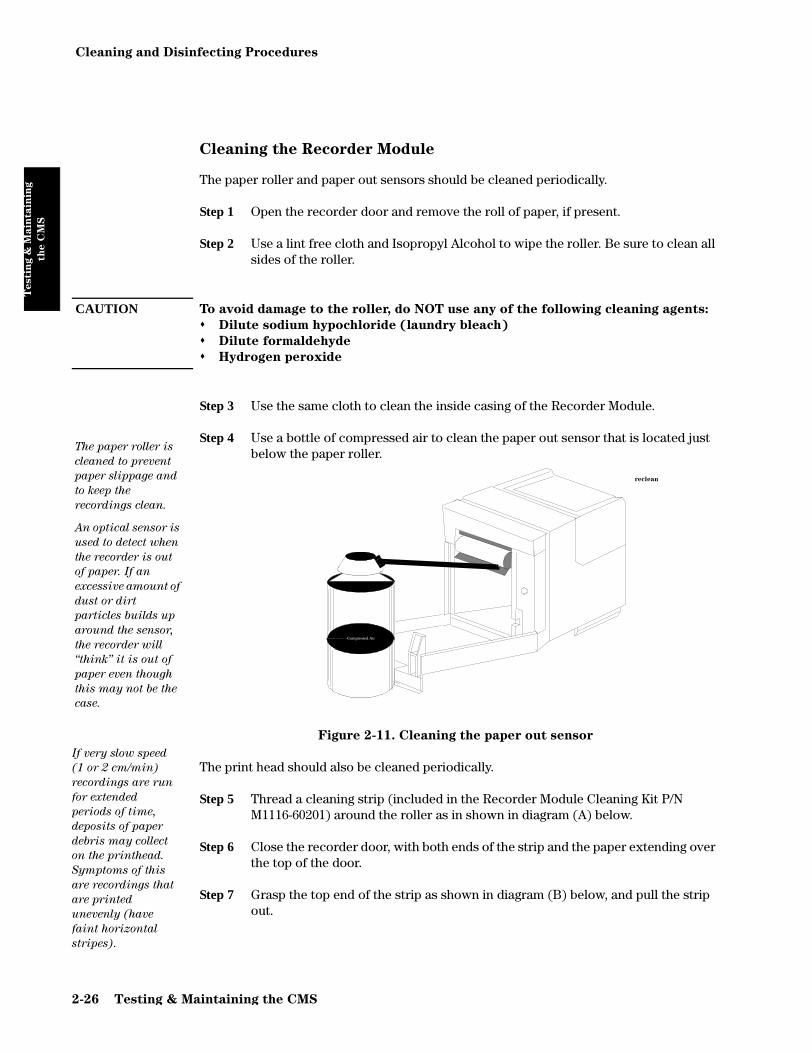
Cleaning and Disinfecting Procedures
Testin
g &
Main
tain
ing
th
e C
MS
Cleaning the Recorder Module
The paper roller and paper out sensors should be cleaned periodically.
Step 1 Open the recorder door and remove the roll of paper, if present.
Step 2 Use a lint free cloth and Isopropyl Alcohol to wipe the roller. Be sure to clean all sides of the roller.
CAUTION To avoid damage to the roller, do NOT use any of the following cleaning agents:
" Dilute sodium hypochloride (laundry bleach)
" Dilute formaldehyde
" Hydrogen peroxide
Step 3 Use the same cloth to clean the inside casing of the Recorder Module.
Step 4 Use a bottle of compressed air to clean the paper out sensor that is located just below the paper roller.
Figure 2-11. Cleaning the paper out sensor
The print head should also be cleaned periodically.
Step 5 Thread a cleaning strip (included in the Recorder Module Cleaning Kit P/N M1116-60201) around the roller as in shown in diagram (A) below.
Step 6 Close the recorder door, with both ends of the strip and the paper extending over the top of the door.
Step 7 Grasp the top end of the strip as shown in diagram (B) below, and pull the strip out.
The paper roller is
cleaned to prevent
paper slippage and
to keep the
recordings clean.
An optical sensor is
used to detect when
the recorder is out
of paper. If an
excessive amount of
dust or dirt
particles builds up
around the sensor,
the recorder will
“think” it is out of
paper even though
this may not be the
case.
Compressed Air
reclean
If very slow speed
(1 or 2 cm/min)
recordings are run
for extended
periods of time,
deposits of paper
debris may collect
on the printhead.
Symptoms of this
are recordings that
are printed
unevenly (have
faint horizontal
stripes).
2-26 Testing & Maintaining the CMS

Cleaning and Disinfecting Procedures
Testin
g &
Main
tain
ing
th
e C
MS
Step 8 Open the door, re-thread the paper, and resume normal operation. (For best results use only Philips Recorder Paper - P/N 40477A/B.)
Figure 2-12. Cleaning the Printhead of the Recorder Module
Cleaning the Blood Analysis Module
The filter for the ventilator fan should be cleaned periodically.
Step 1 Slide the filter cover on the underside of the module to the left and remove.
Step 2 Remove the filter from the cover.
Step 3 Rinse the filter under running water to remove any dust or debris.
Step 4 Shake the filter and leave to dry before replacing in the cover.
A B120mm H X 150mm W
recln1
Testing & Maintaining the CMS 2-27

Cleaning and Disinfecting Procedures
Testin
g &
Main
tain
ing
th
e C
MS
2-28 Testing & Maintaining the CMS

Chapter 3 Troubleshooting the CMS
Tro
ub
lesh
oo
tin
g t
he
CM
S
This chapter describes how to troubleshoot the CMS as a system. Once a fault has been isolated to either the display module or computer module, this chapter tells you how to further isolate faults to the field replaceable assemblies. All references to the CMS also refer to ACMS or NCMS unless specifically stated.
Objectives
This chapter shows you how to:
• Recognize a properly operating CMS.
• Identify symptoms of improper operation for the CMS.
• Use any symptoms or indications to identify a fault as being in the display module, computer module, or the plug-in parameter modules.
• Further isolate faults down to field replaceable assemblies.
Concepts
This chapter uses visual indications, error codes, and other operational symptoms to help you diagnose problems with the CMS. Symptoms have been grouped to form troubleshooting modules.
Each troubleshooting module contains procedures for isolating faults based on the symptoms, any supporting theory as to why you are being told to do a certain procedure, and any additional rationale that will help you to isolate faults. The following table lists the troubleshooting modules.
Troubleshooting the CMS 3-1

Procedure Overview
Tro
ub
lesh
oo
tin
g t
he
CM
S
Procedure Overview
Table 3-1 Troubleshooting Procedure Overview
Topic Page
General System Troubleshooting 3-3
Troubleshooting Module 1 - Fixing Display / Power Supply Problems 3-7
Troubleshooting Module 2 - Computer Module Faults 3-14
Troubleshooting Module 3 - Fixing Recorder Problems 3-35
Troubleshooting Module 4 - Fixing Handheld Keypad Problems 3-36
Troubleshooting Module 5 - Fixing Printing Problems 3-37
Troubleshooting Module 6 - Using the Service Mode 3-39
3-2 Troubleshooting the CMS

General System Troubleshooting
Tro
ub
lesh
oo
tin
g t
he
CM
S
General System Troubleshooting
The following flowcharts are a good place to begin troubleshooting the CMS. Each bold box represents a general symptom of the monitor. After identifying the appropriate symptom, follow the arrow from the box to the possible corrective actions. If the first action listed does not resolve your problem, then proceed to the next box. If you need more help, proceed to the appropriate Troubleshooting Module.
The letter with a box around it is a guide to help you through the flowchart. The corresponding letter on the following page marks your place in the chart.
Contrast and/or brightness controls set too low. Turn to right to obtain maximum brightness or contrast. For M1095A, if necessary exchange backlight.
Power lead disconnected or switched off. Connect lead/switch on.
Display fuses open. Verify fuse values and replace.
DC/DC cable or video cable disconnected or faulty. Check/exchange cables as necessary.
Blue HIF connector of monochrome display inside CRT bezel improperly connected (M1092A display only). Check/reconnect HIF.
Blank Display; no picture; no error messages.
A
For M1095A: Change video cable. Check/exchange flatscreen assembly. (Also applicable to XGA flatscreen displays.)
Troubleshooting the CMS 3-3

General System Troubleshooting
Tro
ub
lesh
oo
tin
g t
he
CM
S
Blank Display; no picture; no error messages.
Card placement in backplane incorrect or Faulty Function Card.
Check if CPU Cards are in correct slots, as shown in Table 1-10
Switch monitor off/on and examine LEDs on function cards.
- If system is connected to any external tools, disconnect tool.- Check backplane for correct EPROM.- Check backplane for correct Cards/CPC Card (See Table 1-10).- Check EEPROM, re-program if necessary.
Only one green LED on each CPU Card keeps blinking. No red LED stays on.
- Exchange CPC Card with another CPC Card.- Remove one APP_CPU after the other. If LED behavior changes,
exchange the last card removed.- Exchange Utility CPU.- Remove all cards except DC/DC Converter and Utility CPU. Then
insert one APP_CPU after the other. When a red LED stays on, exchange the last CPU inserted.
Red LEDs on ALL CPU cards stay on.
A
B
3-4 Troubleshooting the CMS

General System Troubleshooting
Tro
ub
lesh
oo
tin
g t
he
CM
S
- M1092A/94A - SMPS LED on, or- M1094B - all 4 SMPS LEDs on:
Reconnect/exchange Line Filter (M1094A color display only)Reconnect/exchange DC/DC Converter.Exchange SMPS.
- M1092A/94A - SMPS LED off: Exchange SMPS- M1094B - one or more SMPS LEDs off: Exchange SMPS.- M1047A - one green LED off: Exchange unit.- M1109A - one green LED off: Exchange part or unit.- M1046B Internal Power Supply - Green LED off: exchange fuse or
unit.
No LEDs on Function cards illuminated. Check SMPS LED(s).
Unidentified illumination sequence. Remove EPROM Cards.
All green LEDs on each CPU start blinking after 10-20 seconds.
- Exchange Display Controller Card.- Check/ exchange Display.
- If the card with red LED is the UTIL_CPU, ensure that the firmware HI byte and LO byte OTPs are in the correct locations, and are properly oriented.
- If CPU with red LED is only card in cluster, exchange it.
All three LEDs on each function card on for < 1 second. On one function card the red LED stays on (5 seconds).
B
Troubleshooting the CMS 3-5

General System Troubleshooting
Tro
ub
lesh
oo
tin
g t
he
CM
S
Keyboard and front panel switches not operating. Computer Module resets itself periodically.
HIL cable between Display or External Alarm Device and Computer Module is reversed. Reconnect cable, matching the dot indicators.
Faulty HIL cable. Exchange HIL cable.
Faulty HIF board or blue HIF connector in Display bezel. Exchange HIF board.
Faulty Utility CPU Card. Exchange Utility CPU.
System resets and all Patient Data is lost.
SRAM checksum error on start-up. In Service Mode, perform the Extended Test. If the test indicates a faulty card, replace it.
Some or all waves/numerics missing.
Plug-in Module(s) or Module Rack problem. See Chapter 4 “Troubleshooting the Plug-in Modules” for the module(s) in question.
Overview (SDN) user default settings automatically reset to factory defaults.
For CMS Releases A - C: SDN connection has been interrupted (either through SCC power down, or SDN cable disconnection). In Configuration Mode, reconfigure the user defaults for all Overview.
3-6 Troubleshooting the CMS

Objectives
Tro
ub
lesh
oo
tin
g t
he
CM
S
Troubleshooting Module 1 - Fixing Display / Power Supply Problems
This module shows you how to troubleshoot problems based on symptoms given by a faulty display. Use this module when your CMS display is blank, showing incorrect data, or if you are referred to this module from another procedure.
Objectives
In order to meet this chapter’s goal, you should be able to:
• Identify faulty conditions.
• Determine if your fault lies in the display or in the computer module.
• Know the likely causes of the fault and the likely remedy of the fault.
Concepts
The display monitors (M1092A - monochrome, M1094A/94B - color, M1095A - color flatscreen, or XGA-compatible display) use basically the same signal path to display patient data on the screen. The big difference is in the type of display controller cards used. The M1092A uses a display controller card called the DSPC. Both the M1094A and M1094B use a color display controller card called the CDSPC. Older versions of the CDSPC did not have enough RAM and two CDSPC cards had to be used. However, the newer versions of the CDSPC contain the necessary RAM and only one is needed.
The Application CPU in the computer module produces the data to be displayed. The DSPC and CDSPC cards control the mechanism of displaying the information on the screen. All of the inputs to the CRT displays come through a 9-pin D-type video-in plug on the rear of the display.
The Flatscreen uses one display controller card called DSPC_FLAT. All the inputs to the display come through a 25-pin twisted pair cable plugged in at the rear of the Flatscreen.
The XGA-compatible display uses one display controller card called CDSPC_XGA. All the inputs to the display come through a standard 15-pin cable.
To troubleshoot a faulty display condition perform the following procedure.
Troubleshooting the CMS 3-7

Procedures
Tro
ub
lesh
oo
tin
g t
he
CM
S
Procedures
If the CRT display is blank...
If the display is blank, the first thing to check is the green LED near the power switch on the front of the display module. When the CMS is plugged into a correct power source and the power switch is pressed to ON, this LED should illuminate GREEN.
When you verify the two conditions are true (CMS plugged in and power switch ON) and the LED is not GREEN, check the fuse. If the fuse is blown, replace the fuse. If fuse continues to blow, there is a problem in the display, and the display should be replaced.
If the fuse is good and the LED is not GREEN, it is possible that the low-voltage output from the Switch Mode Power Supply is not present. Proceed to the next step.If the LED is GREEN, and the fuse is good, and the display is blank, proceed to the next step.
The contrast or brightness controls may have been turned down too low. Turn both controls fully to the right and see if this fixes your problem. If nothing at all happens to the screen when you turn the controls to the right, the high voltage output from the SMPS may not be present and the display might need to be replaced. Proceed to the next step.
If when you turn the controls to the right a raster appears, the fault could be in the DC-to-DC converter in the computer module. Look at the rear of the Computer Module and locate the Utility CPU board. The Utility CPU board should have three green LEDs illuminated. If it does not, replace the DC-to-DC converter. If the LEDs are illuminated green, refer to the section CMS System Hardware/Software Problems on page 3-27.
The video cable from the Computer Module to the Display is not connected correctly. Check the connection and reconnect if necessary. If the connection is correct, the cable may be faulty. Replace the cable and see if this corrects the problem.
The blue human interface connector of the monochrome display in the front assembly is improperly connected. Remove the front assembly and check the connector and reconnect if required.
The wrong display controller (DSPC) card is in the Computer Module. If the wrong DSPC Card is in the backplane or the DSPC is missing from the backplane, the display may be blank. Check that the DSPC Card(s) is/are CMS display controller card(s) and that it is in the correct slot.
If the monitor is color, ensure that the DSPC_Color Card (or both a CDSPC_VIDEO and CDSPC_CTRL Card) is plugged into the correct slot(s) in the backplane.
The card placement in backplane is incorrect/faulty function card is present. If the corrective actions in General System Troubleshooting on page 3-3 did not resolve the symptom, refer to section Procedures on page 3-14.
Check power LED.
Check contrast and
brightness
controls.
Check video cable.
Check HIF
connector.
Check DSPC
Card(s).
Check Functional
Cards.
3-8 Troubleshooting the CMS

Procedures
Tro
ub
lesh
oo
tin
g t
he
CM
S
If there is poor display quality, inverse video, incorrect colors, faded image,
ghosting, a scrambled picture, or missing information on the CRT display...
The video termination switch on the rear of the display may be improperly set. If only a main display is being used, the main switch should be placed to Switch ON (in). If a second (remote) display is connected to the main display, the switches should be set as follows:Main: Switch OFF (out) Slave: Switch ON (in)
The video cable from the Computer Module to the Display is not connected correctly. Check the connection and reconnect if necessary. If the connection is correct, the cable may be faulty. Replace the cable and see if this corrects the problem.
If you have a color display, there is a chance the de-gaussing coils of the CRT are faulty. These coils de-magnetize the CRT using two positive temperature coefficient thermistors. The current flow (maximum when cold, minimal when hot) changes as the thermistors heat up. Turn the unit off and wait 30 minutes for the thermistors to return to room temperature. Then turn the unit on. If the problem goes away and then returns after several minutes, suspect the de-gaussing circuit and replace the display.
The display controller in the computer module may be faulty. You can check this by re-booting the unit and checking the Status Log for any error codes concerning the display controller. If so, replace the display controller.
If you suspect the display controller is faulty, but there is no error code in the status log, refer to Procedures on page 3-14 to further isolate the problem.
Another condition can exist where you have a color monitor connected to a monochrome display controller or vice-versa. Check you have a match between your monitor and the display controller card. Refer to Procedures on page 3-14 to check the exact placement of your display controller.
The blue human interface connector in the front assembly is improperly connected. A way to check this is by turning the brightness and contrast controls to both the left and the right. If the screen remains unaffected, remove the front assembly and check the connector and reconnect if required. If the connector is intact, suspect the Human Interface board in the display bezel and replace it.
If you have known waves or numerics missing from the screen but the screen is behaving normally, refer to Troubleshooting Module 3 - Plug-In Module Faults.
If you have come this far and have not fixed your problem, go to Procedures on page 3-14. That module tells you how to check to see if the Computer Module Unit is working correctly. If the Computer Module Unit is working correctly, replace the display.
Check video
termination.
Check video cable.
Check degaussing
coils.
Check display
controller.
Check blue HIF
connector.
Check plug-in
modules.
Go to...
Troubleshooting the CMS 3-9

Procedures
Tro
ub
lesh
oo
tin
g t
he
CM
S
If the (M1095A) Flatscreen Display is blank...
If the Flatscreen Display (M1095A) is blank, the first step is to check the green LEDs on the front of the display and on the power supply. The power supply is one of the following: M1047A Power Supply, a CRT Display (M1092A, M1094A or M1094B), or the M1046B Integral Power Supply. When the CMS is plugged into a correct power source and the power switches on the display and power supply are pressed to ON, both LEDs should illuminate GREEN.
When you verify that the two conditions are true and that the LEDs are not GREEN, check the fuses at the rear of the module that is supplying power, the Power Supply M1047A, CRT Display, or M1046B. Replace any blown fuses. If fuses continue to blow, there is a problem in the Display and/or the Computer Module.
Video/Power Cable Check the video/power cable connection and reconnect if necessary. If the connection is correct, the cable may be faulty. Replace the cable to see if this corrects the problem. Check the video/power cable if: the LED on the M1047A Remote Power Supply is green, the LED on the Flatscreen is blank, and the red LEDs in the Computer Module are inactive.
M1047A Power Supply If you suspect the M1047A Power Supply, test the Remote Control Board to determine whether this board or the Switch-Mode Power Supply itself is faulty. The Remote Control Board has a 12V(AC) input and outputs 12V(DC) to an optocoupler on the SMPS. Output from the SMPS is 60V(DC). Exchange part number for the Remote Control Board is 31192086411FMI. If the SMPS is faulty, replace the complete Power Supply.
If the LEDs are green and the fuses are good but the display is blank, proceed to the next step.
Computer Module Check that the correct cards are located in the correct slots in the Computer Module. In particular check that the Flatscreen Display Controller Board is correctly located. Look at the rear of the Computer Module. The Utility CPU board should have three green LEDs illuminated plus one green blinking LED and the Flatscreen Display Controller Board should have one green blinking LED. Note that the Flatscreen Display Controller Board outputs 60V via the video/power cable to the Flatscreen Display. This board is protected with an SMT fuse.
Flatscreen Display If you suspect the Flatscreen Display, check whether the backlight is defective. See Chapter 5 “Repairing the CMS” for this procedure. Alternatively, the LCD or the video board may be defective. If the LCD is defective, exchange the complete display.
3-10 Troubleshooting the CMS

Procedures
Tro
ub
lesh
oo
tin
g t
he
CM
S
If there is poor display quality on a Flatscreen Display...
Check video cable Check the video cable connection and reconnect if necessary. If the connection is correct, the cable may be faulty. Replace the cable to see if this corrects the problem.
Flatscreen Display Controller The Flatscreen Display Controller Board in the Computer Module may be faulty. You can check this by re-booting the unit and checking the Status Log for any error codes concerning the display controller.
If you suspect that the display controller is faulty but there is no error code in the status log, refer to Troubleshooting Module 2 - Computer Module Faults to further isolate the problem.
Verify the integrity of the display Go to demo mode to verify the integrity of the display. The ECG complexes should be regularly spaced and all portions of the ECG waveform should be clear and visible. (A small number of missing pixels is normal with all LCD displays but, if the ECG waveform is not clear, this is an indication of an unacceptable number of pixel failures.)
It may be useful to use the white test picture in service mode.
If the display exhibits other quality problems such as misalignment or jitter, and you have checked the Video/Power cable and the Flatscreen Display Controller Card, this means that there is a problem in the Flatscreen Display itself and the display should be replaced. (For board-level troubleshooting, sound or control problems indicate that the HIF board is faulty; problems with the picture indicate that the video board is faulty.)
Display Brightness The brightness control may be turned too low or the flatscreen display may not be angled for optimum viewing. If the display is still too dim with the brightness control at maximum, change the backlight. See Chapter 5 “Repairing the CMS” for this procedure.
Check plug-in modules If you have known waves or numerics missing from the screen but the screen is behaving normally, refer to Troubleshooting Module 3 - Plug-In Module Faults.
Troubleshooting the CMS 3-11

Procedures
Tro
ub
lesh
oo
tin
g t
he
CM
S
If an XGA Display is blank...
If the XGA Display is blank, the first step is to check the green LEDs on the front of the display and power supply. When the CMS is plugged into a correct power source and the power switches on the display and power supply are pressed to ON, both LEDs should illuminate GREEN.
When you verify that the two conditions are true and that the LEDs are not GREEN, check the fuses at the rear of the display, power supply and the computer module. Replace any blown fuses. If fuses continue to blow, there is a problem in the Display and/or the Computer Module.
Video/Power Cable Check the video/power cable connection and reconnect if necessary. If the connection is correct, the cable may be faulty. Replace the cable to see if this corrects the problem.
Power Supply If you suspect the Power Supply, test the Remote Control Board to determine whether this board or the Switch-Mode Power Supply itself is faulty. The Remote Control Board has a 12V(AC) input and outputs 12V(DC) to an optocoupler on the SMPS. Output from the SMPS is 60V(DC). Exchange part number for the Remote Control Board is 991920864111FMI. If the SMPS is faulty, replace the complete Power Supply.
If the LEDs are green and the fuses are good but the display is blank, proceed to the next step.
Computer Module Check that the correct cards are located in the correct slots in the Computer Module. In particular check that the Flatscreen Display Controller Board is correctly located. Look at the rear of the Computer Module. The Utility CPU board should have three green LEDs illuminated plus one green blinking LED and the Flatscreen Display Controller Board should have one green blinking LED. Note that the Flatscreen Display Controller Board outputs 60V via the video/power cable to the Flatscreen Display. This board is protected with an SMT fuse.
Flatscreen Display If you suspect the Flatscreen Display, check whether the backlight is defective. See Chapter 5 “Repairing the CMS” for this procedure. Alternatively, the LCD or the video board may be defective. If the LCD is defective, exchange the complete display.
NOTE Note: For the XGA display, the switch on the External Alarm Device operates the computer module; the green LED on the Alarm Device shows whether it is on. If there are technical problems with the XGA display, consult the display device’s own service documentation.
3-12 Troubleshooting the CMS
Procedures
Tro
ub
lesh
oo
tin
g t
he
CM
S
If the TouchScreen operation is malfunctioning...
Check cable connection between the RS232 connectors of the display and the function box. Reconnect, if necessary.
Perform a visual inspection of the overlay. If the overlay is visibly damaged, it has to be replaced.
Check the RS232 configuration:
Step 1 Enter Config Mode and press .
Step 2 Press . This leads you to the RS232 setup window.
Step 3 Make sure that the entries behind Port 1-4 show the correct devices. If not, select the correct devices for each port.
Step 4 If you had to change the configuration, save it and switch power off and on.
Step 5 If the problem still exists, proceed with the next step.
Perform a Touch Screen calibration:
Step 1 Enter Config Mode and press .
Step 2 Press . This leads you to the Touch Screen Setup window.
Step 3 Perform the calibration procedure. Follow the steps as shown on the screen.
If the font appears to be incorrect...
After installing a display controller card, if the font appears to be incorrect, it may be because the Font ROM Switch setting for the language is incorrect. See “Configuring the Display Controller Card” in Chapter 5 “Repairing the CMS” for details.
Monitor Setup
RS 232
Monitor Setup
Touch Setup
Troubleshooting the CMS 3-13

Objectives
Tro
ub
lesh
oo
tin
g t
he
CM
S
Troubleshooting Module 2 - Computer Module FaultsThis module shows you how to troubleshoot problems based on symptoms given by a faulty Computer Module. Use this module when you suspect you have a problem in your Computer Module, or when you are referred to this module from another procedure.
Objectives
In order to meet this chapter’s goal, you should be able to:
• Identify faulty conditions.
• Verify the correct function card locations in the Computer Module.
• Know what are the likely causes of the fault and what are the likely remedies.
• Use the Status Log to check for error codes, and other service information.
• Interpret error codes and how to use them to isolate faults.
Concepts
Each function card in the CMS comes with a red LED that illuminates to indicate a fault with the card. There are also green LEDs on each function card that show the normal operation of the system. Also associated with most fault conditions are Error Codes that can be viewed in the Status Log of the operating modes. This module uses each of these items to isolate faults and to determine the health of the Computer Module.
Error Codes
The first line of fault isolation is the Error Codes. Whenever one of the function cards is unable to perform an operation, an error code is generated. Error codes can be for fatal and non-fatal errors. Fatal errors are errors which cause the CMS to re-start. Non-fatal errors are general errors that are not significant enough to affect normal CMS operation.
Fatal error codes can be found in the Status Log while in any of the four operating modes. In the Service Mode, the Status Log also displays Non-fatal error messages. If an error occurs when the CMS is starting up, a start-up error code is generated and displayed at the top of the screen. Start-up error codes give similar information to that of the Status Log entries, except the codes are given are in hexadecimal notation.
3-14 Troubleshooting the CMS

Using Error Codes
Tro
ub
lesh
oo
tin
g t
he
CM
S
What an Error Code Tells You
When you look at an error code in the Status Log, you can see the following information:
Using Error Codes
This section includes procedures on how to access the Status Log in the various operating modes, and what actions to take when a fatal error is encountered. This module includes error code lists for the errors reported by the CMS, grouped by Device ID, and the recommended course of action for each fault.
Two possible conditions may occur in which the CMS generates error code information. These conditions are:
• A fault causing the system to restart occurs, but upon restarting the fault clears. If this happens, begin with the first step of this procedure.
• A fault causing the system to repeatedly restart occurs. If this occurs, go to the segment of this procedure that explains Using Start-up Error Codes.
Table 3-2 Error Code Description
Field Description
H, W, C or F H, W, and C denote fatal errors which have caused a Hot, Warm, or Cold start. F denotes a Fatal error without deference to the type of restart caused.
Card Name RACK_IF, for example
Part Number of function card M1088-66501, for example
Device ID Code The number referring to a hardware device or software module and used to indicate the location of a fault.
Slot number Position of the faulty or reporting card in the computer module unit.
Error code Number describing the type of fault identified. The error code tables in this module give more details.
Date\Time Date and time the error occurred.
Troubleshooting the CMS 3-15

Using Error Codes
Tro
ub
lesh
oo
tin
g t
he
CM
S
Using Status Log Error Codes
Access the Status Log. You do this by:
Step 1 From any of the operating modes, press (or ) to bring up to the Selection Window.
Step 2 Use the ARROW keys to move the highlighting to the row of softkeys that include Status Log.
Step 3 Press the softkey. The screen displays the Status Log.
Once in the Status Log, check it for entries that have an H, W, C, or F entered in their first field. This identifies fatal errors. We are only concerned with fatal errors because these are the errors which are significant enough to affect the CMS operation. Each fatal error shows you the following:
• The Function card which has reported the fault,
• The part number of the functions card,
• The device ID code which indicates the hardware device or software piece which caused the fault,
• Slot number of the function card reporting the fault,
• The error code describing the fault identified,
• The date and time the fault occurred. This is important because the status log contains the fourteen most recently occurring errors, with the most recent errors at the top.
If you have more than one error message for a single incident, deal with the first occurring error message (error messages are listed chronologically by date and time) before dealing with the others pertaining to the incident.
If you have fatal error codes in the Status Log, and you proceed with an EndCase (discharge from the monitor), the monitor will not enter Standby Mode. Instead, the monitor will go to Monitoring Mode. That is why it is a good practice to purge the Status Log after you have dealt with or recorded each error.
Using Start-up Error Codes
If your CMS is re-starting repeatedly, a start-up error code may appear at the top of the screen. The start-up error code gives information similar to that displayed in the status log, except the start-up error codes are listed in hexadecimal notation. These codes are identified by an “H” at the end of the code.
Start-up Error Messages require the same corrective action as the error messages found in the status log. The Error Code Listings at the end of this module contain the hexadecimal equivalent for each error code and device ID.
Monitor Setup Instrument Config
Status Log
3-16 Troubleshooting the CMS

Using Error Codes
Tro
ub
lesh
oo
tin
g t
he
CM
S
How Device ID Codes and Error Codes Relate to Each Other
For troubleshooting the CMS, the device ID code and the error code portions of the error message have an important relationship. Each device ID has a block of error codes assigned to it. A separate Error Code Listing has been setup for CMS’s operating system, device ID code 16400, since most fatal errors occur in this area.
Refer to the Error Code Listing in this module for the device ID indicated by the error code. There are two tables in this module. The first is for device ID code 16400 (4010H). The second is for all other device IDs. The corrective actions listed in these tables are listed in one of the follow ways:
• For some device ID 16400 (4010H) corrective actions:
• See “CMS System Hardware Configuration Problems” on page 3-23.
• See “CMS System Hardware/Software Problems” on page 3-27.
• See “CMS System RAM Problems” on page 3-27.
• For all other device IDs, specific corrective action depends on the type of error encountered. The error code listing gives you detailed instructions for each situation.
Identifying the Slot Number Using the Error Code Chart
For error codes in the range 1000 to 1999 (03E8Hto 07CFH) with Device ID 16400 (4010H), you can directly identify the slot number of the faulty board, using the hexadecimal error code and the following chart.
Use the error code chart as follows:
Step 1 Locate the first three digits of the hex error code in the columns across the top of the chart.
Step 2 Locate the last digit of the hex error code down the left-hand row of the chart.
Step 3 Read the number at the point in the chart where the row and column intersect. This represents the slot number of the faulty board in the Computer Module. These error codes will normally be provided in hexadecimal at system start-up as part of a start-up error message. For most start-up errors, replace the card in the slot identified by this chart.
Troubleshooting the CMS 3-17

Using Error Codes
Tro
ub
lesh
oo
tin
g t
he
CM
S
Device ID 16400 (or 4010H) Error Code Lists
The first table gives the error code listing for device ID 16400 (4010H). Each error code entry provides the following information:
Status Log Errors - the decimal number range the error code gives in its status log entry.
Start-up Error - the hexadecimal number range of the start up error code.
Possible Cause - the possible cause for the error code report.
Corrective Action - actions which are designed to isolate the fault to a replaceable assembly.
Table 3-3 Error Code Chart for Slot Location (Device ID 16400 or 4010H)
Device ID 16400 (4010H) Only
First Three Digits (Hex Error Code)
03E 03F 040 041 042 043 044 045 046 047 048 049 04A 04B 04C 04D 04E 04F
050 051 052 053 054 055 056 057 058 059 05A 05B 05C 05D 05E 05F
060 061 062 063 064 065 066 067 068 069 06A 06B 06C 06D 06E 06F
070 071 072 073 074 075 076 077 078 079 07A 07B 07C
Last
Dig
it o
f H
ex E
rror
Cod
e
0 8 24 8 24 8 24 8 24 8 24 8 24 8 24 8 24 8
1 9 25 9 25 9 25 9 25 9 25 9 25 9 25 9 25 9
2 10 10 10 10 10 10 10 10 10
3 11 11 11 11 11 11 11 11 11
4 12 12 12 12 12 12 12 12 12
5 13 13 13 13 13 13 13 13 13
6 14 14 14 14 14 14 14 14 14
7 15 15 15 15 15 15 15 15 15
8 16 16 16 16 16 16 16 16 16
9 1 17 1 17 1 17 1 17 1 17 1 17 1 17 1 17 1 17
A 2 18 2 18 2 18 2 18 2 18 2 18 2 18 2 18 2 18
B 3 19 3 19 3 19 3 19 3 19 3 19 3 19 3 19 3 19
C 4 20 4 20 4 20 4 20 4 20 4 20 4 20 4 20 4 20
D 5 21 5 21 5 21 5 21 5 21 5 21 5 21 5 21 5 21
E 6 22 6 22 6 22 6 22 6 22 6 22 6 22 6 22 6 22
F 7 23 7 23 7 23 7 23 7 23 7 23 7 23 7 23 7 23
3-18 Troubleshooting the CMS

Using Error Codes
Tro
ub
lesh
oo
tin
g t
he
CM
S
Table 3-4 Error Code Listing for Device ID 16400 (or 4010H)
Status Log
Errors
Start-up
Errors
Possible
Cause
Corrective
Action
1 - 99 0001H - 0063H Hardware test failure in the first boot stage.
RAM problem- refer to the corrective action on page 3-27.
100 - 199 0064H - 00C7H Microprocessor interrupts due to a Hardware or Software problem in given slot or cluster.
Hardware/Software problem- refer to the corrective action on page 3-27.
200 00C8H MPB chip errors: Can be caused by hardware defects on the indicated CPU as well as hardware defects on any other MPB participant (Master Cards: for example Util CPU, APP_CPU, DSPC Ctrl, and others) in the system.
Hardware/Software problem- refer to the corrective action on page 3-27.
201 - 202 00C9H - 00CAH System configuration problem or invalid contents of the Util_CPU EEPROM.
System Configuration problem - refer to the corrective action on page 3-23.
203 - 239 00CBH - 00EFH Same as error 200 Hardware/Software problem- refer to the corrective action on page 3-27.
240 00F0H Message transmission problem. System Configuration problem - refer to the corrective action on page 3-23.
241 00F1H Same as errors 203 - 239. Hardware/Software problem- refer to the corrective action on page 3-27.
242 00F2H Message transmission problem. System Configuration problem - refer to the corrective action on page 3-23.
243 - 299 00F3H - 012BH Same as errors 203 - 239. Hardware/Software problem- refer to the corrective action on page 3-27
300 - 301 012CH - 012DH EPROM checksum incorrect. With 10 and/or 15 MHz APP_CPU's in backplane, replace the EPROM in the cluster of the given slot.
With 40 MHz CPC with Daughter Card in backplane, replace the Daughter Card.
With 40 MHz CPC with Flash EPROM in backplane, reprogram Flash EPROM. If you still have a problem, replace CPC Card.
305 - 307 0131H - 0133H Boot errors on CPC Card - software upgrade problem (for example: Flash Card corrupt). Will only occur when CPC Programming Tool is connected.
Switch the System off, re-insert the Upgrade Tool and switch the System on again.
Replace the Flash Card.
Replace the CPC Card in slot 12.
310 - 315 0136H - 013BH EPROM version and EEPROM version not compatible.
System Configuration problem - refer to the corrective action on page 3-23.
Troubleshooting the CMS 3-19

Using Error Codes
Tro
ub
lesh
oo
tin
g t
he
CM
S
330, 335 014AH, 014FH Only detected by the APP_CPU in slot 5 - indicates that another MPB participant (Master Card) does not boot up as required. There is no error in the indicated slot.
Hardware/Software problem- refer to the corrective action on page 3-27.
340, 356, 370 0154H, 0164H, 0172H
Indication of communication problems between the APP_CPU in slot 5 and another MPB participant. The slot code may be incorrect.
Hardware/Software problem- refer to the corrective action on page 3-27.
380 017CH Firmware revision is incompatible with current Software revision.
System Configuration problem - refer to the corrective action on page 3-23.
390 0186H Indication of a communication problem between the CPC in slot 12 and another MPB participant. The slot code may be incorrect.
Hardware/Software problem- refer to the corrective action on page 3-27.
Exchange the Utility CPU Card.
391, 392 0187H, 0188H Out of memory on the CPC Card. Replace CPC Card.
393 0189H Plugged CPC isn't compatible with the Philips CMS Patient Monitoring System.
Ensure that the correct Software is loaded on the CPC Card (check SW Part Number).
400 - 409 0190H - 0199H Out of memory. With 10MHz and/or 15MHz APP_CPU's in backplane:Check Data Management Option and SRAM board compatibility. (See Parts Lists).
Replace RAM Card, if present in same cluster.
Replace CPU Card in indicated slot.
With a 40MHz CPC in backplane, replace the CPU Card in indicated slot.
410 - 419 019AH - 01A3H Missing file errors. System Configuration problem - refer to the corrective action on page 3-23.
420 - 449 01A4H - 01C1H Utility CPU / EEPROM error. System Configuration problem - refer to the corrective action on page 3-23.
500 - 699 01F4H - 02BBH Indicates a Software problem that cannot be solved by hardware exchange.
Check that the installed software is a released version. Contact your local Response Center. Install released software.
700 - 799 02BCH - 031FH Communication problem between two CPUs.
System Configuration problem - refer to the corrective action on page 3-23.
Hardware/Software problem- refer to the corrective action on page 3-27.
800 - 899 0320H - 0383H Configuration problem. System Configuration problem - refer to the corrective action on page 3-23.
Table 3-4 Error Code Listing for Device ID 16400 (or 4010H)
Status Log
Errors
Start-up
Errors
Possible
Cause
Corrective
Action
3-20 Troubleshooting the CMS

Using Error Codes
Tro
ub
lesh
oo
tin
g t
he
CM
S
900 - 914 0384H - 0392H Something within the System memory has changed unexpectedly. This is usually caused by a RAM problem.
One or more pins on a Function Card may be bent.
RAM problem- - refer to the corrective action on page 3-27.
Remove and replace the affected Function Card.
915 0393H One of the CPUs has failed to send a test message to the next CPU. The reported slot code will not identify the defective CPU Card.
Swap/replace APP_CPU's one by one until the faulty card is found. Replace faulty card.
916 - 919 0394H - 0397H Something within memory has changed unexpectedly (see error range 900-914).
RAM problem- - refer to the corrective action on page 3-27.
920 0398H Indicates a missing 32 ms interrupt on the CPU in the reported slot. This could be caused by a poor connection (CPU, backplane, etc.) or a failure on the Util CPU.
Inspect backplane connectors.
Swap/replace APP_CPU Card in given slot.
Swap/Replace UTIL_CPU Card.
921 - 999 0399H - 03E7H Something within memory has changed unexpectedly (see error range 900-914).
RAM problem- - refer to the corrective action on page 3-27.
1000 - 1031 03E8H - 0407H Missing mandatory card in slot indicated. Consult the Error Code Chart in Table 3-3 on page 3-18 to determine the slot of the misplaced CPU Card - place the CPU Card in the correct slot.
Check backplane in Table 1-10 Function Card Placement on page 1-23 for correct Function Card placement.
System Configuration problem - refer to the corrective action on page 3-23.
1032 - 1063 0407H - 0427H Wrong boot firmware revision on APP_CPU in slot indicated.
1064 - 1095 0428H - 0447H Insufficient MPB RAM on CPU in slot indicated.
Hardware/Software problem- refer to the corrective action on page 3-27.
Consult the Error Code Chart in Table 3-3 on page 3-18 to determine the slot of the defective CPU Card. Exchange the defective card.
1096 - 1127 0448HH - 0467H No Extended Test result due to Hardware problem.
1128 - 1159 0468H - 0487H Extended Test failed. Consult the Error Code Chart in Table 3-3 on page 3-18 to determine the slot of the defective CPU Card. Exchange the defective card.
Table 3-4 Error Code Listing for Device ID 16400 (or 4010H)
Status Log
Errors
Start-up
Errors
Possible
Cause
Corrective
Action
Troubleshooting the CMS 3-21

Using Error Codes
Tro
ub
lesh
oo
tin
g t
he
CM
S
1160 - 1191 0488H - 04A7H RAM Card size not compatible with backplane configuration.
Ensure the correct RAM Card is installed in the backplane, and check backplane on Table 1-10 Function Card Placement on page 1-23 for correct Function Card placement.
Consult the Error Code Chart on page 3-18 to determine the slot of the defective CPU Card. Exchange the cards in cluster one by one.
1192 - 1223 04A8H- 04C7H EEPROM configuration of the card in the slot indicated is not compatible to the Hardware configuration.
1224 - 1255 04C8H - 04E7H Wrong CPU type in slot indicated. Check backplane on Table 1-10 Function Card Placement on page 1-23 for correct Function Card placement.
Consult the Error Code Chart on page 3-18 to determine the slot of the defective CPU Card. Exchange the defective card.
1256 - 1287 04E8H - 0507H CPU is too slow in slot indicated.
2100 0834H Unused card in the System (non-fatal error).
Check backplane on Table 1-10 Function Card Placement on page 1-23 for correct Function Card placement, remove unused card.
2110 - 2152 083EH - 0866H Unreleased Software installed (non-fatal error).
Contact your local response center - install released Software.
2160 0870H An extra CPU is present in indicated slot (non-fatal error).
Remove unused CPU Card in indicated slot.
2170 - 3300 087AH - 0C54H Hardware problem. With 10 and/or 15MHz APP_CPU's in backplane, replace the EPROM boards.
With 40MHz CPC in backplane: 1. Replace the CPC Card. 2. Exchange the card in the indicated slot. 3. Exchange all other APP_CPUs one by one.
Table 3-4 Error Code Listing for Device ID 16400 (or 4010H)
Status Log
Errors
Start-up
Errors
Possible
Cause
Corrective
Action
3-22 Troubleshooting the CMS

CMS System Hardware Configuration Problems
Tro
ub
lesh
oo
tin
g t
he
CM
S
CMS System Hardware Configuration Problems
This section tells you how to deal with hardware configuration problems. These problems generally occur when a function card is placed in the wrong slot or if a function card is incompatible with the CMS configuration.
Concepts
Types of Function Cards
There are two basic types of function card: Master Cards and Local Cards.
• Master Cards - The master cards are those cards that have both a Central Processing Unit (CPU) and a Message Passing Bus interface (MPB_IF). These cards may also communicate with local cards (for example SRAM, EPROM and CDSPC_VIDEO) over the Local Bus. Only one of each master card type may be used in the same Computer Module, with the exception of the Application CPU and the display controllers.
• Local Cards - The Local Cards have no MPB_IF and can only communicate with the master card via the Local Bus within a cluster of connectors. These cards may be used on every cluster containing a master board within the Computer Module. All the Local Cards may be used more than once in the Computer Module, with the exception of the SDN_IF and the Rack_IF S-Ram, and more than one Local Card may used by a master card. Therefore, an identifier is used so the master card can tell the Local Card type and position in the cluster. This may also be used to test the board for compatibility with the master card.
Interconnections
Three types of card in the backplane interconnect. The types are as follows:
• Master Cards. These cards are connected to both the MPB and the local bus.
• System Interfaces. These are master cards that are connected to the MPB but have no connection to the local bus.
• Local Cards. As the name suggests, these cards are only connected to the local bus and have no MPB connection.
The RS232_IF may
be installed in any
slot of the
Computer Module
as it has no
connection to the
Local Bus. The DC/
DC Converter also
has no connection
to the Local Bus
but must be
inserted to the left
of slot 21 of the
Computer Module,
because it may
damage the system
if placed in
another slot.
In addition,
system interfaces
and local cards
may be interfaces
to systems outside
the CMS.
Troubleshooting the CMS 3-23

CMS System Hardware Configuration Problems
Tro
ub
lesh
oo
tin
g t
he
CM
S
Rules for Card Placement
The rules governing where particular function cards may be positioned in the backplane are as follows:
• The DC/DC converter must be placed in the unnumbered slot (cluster 1).
• The Rack Interface card must be placed in slot 18.
• If required, the DSPC_Lang card must be placed in slot 3.
• If present, a 40MHz CPC card must be inserted in slot 12.
• Master Cards can only be used once within any local cluster.
• Local Cards must be located in the same cluster as their associated master card. Therefore, the following cards must be clustered as indicated:
• SDN Interface and Rack Interface with Util_CPU
• CDSPC_Video with CDSPC_Control
• EPROM with an APP_CPU
• SRAM with an APP_CPU
• The following cards, which have external connections, must be inserted in the rear of the backplane:
• UTIL_CPU
• RS-232 Interface
• SDN Interface
• HDLC Interface
• Analog Interface
• Display Controller
The end of this section gives the delivered configurations for the different releases of the CMS.
3-24 Troubleshooting the CMS

CMS System Hardware Configuration Problems
Tro
ub
lesh
oo
tin
g t
he
CM
S
Troubleshooting the CMS 3-25
Procedures
The procedures for fixing CMS configuration problems vary depending upon your configuration and the type of APP_CPU or CPC you have. In general, the procedure for your configuration requires you to perform some visual checks, verify you are operating with the proper software revision for your CMS, and then perform fault isolation procedures based on the hardware configuration.
If the Monitor reboots continuously, examine the LEDs of the Function Cards:
Step 1 If the red LED of the Master CPU Card stays on, check if another CPU Card is plugged in the same cluster - there should be only one CPU per cluster. Otherwise exchange the CPU Card in the reported slot.
Step 2 If the red LED on the Master CPU does not stay on, refer to Table 3-5 General Error Code Listing for Other Device IDs on page 3-28 to identify the
faulty card.
For monitors with 10MHz or 15MHz APP_CPUs:
Step 1 Verify that the Master and Slave EPROM Cards are plugged in the correct slots, and make sure they belong to the same software release.
Step 2 Verify the correct EEPROM part number by:
• checking the number displayed in the “Monitor Revision” screen or
• using the appropriate cloning tool if the monitor is rebooting continuously or the display is blank.
Step 3 If the part number is correct, reprogram the EEPROM to the factory defaults using the appropriate cloning tool.
If the preceding actions do not correct the configuration problem, try the following:
Step 1 Replace the EEPROM.
Step 2 Replace the Utility CPU.
Step 3 Replace EPROM Cards.
For monitors with a 40MHz CPC (Flash EPROM):
Step 1 Verify the correct EEPROM part number by:
• checking the number displayed in the “Monitor Revision” screen or,
• using the CPC cloning tool if the monitor is rebooting continuously or the display is blank.If the part number is correct, reprogram the EEPROM to the factory defaults using the CPC programming tool.
The LED behavior
on the 40 MHz CPC
Card is the same as
the behavior on the
10 and 15 MHz
Master CPU Cards.
For Monitors with
10 MHz and 15
MHz APP_CPU
Cards, the
APP_CPU in slot 5
of the System's
backplane is the
Master CPU.
For Monitors with
the CPC Card (40
MHz), the card in
slot 12 of the
System's backplane
configuration is the
Master CPU.
The Master CPU
reports errors in the
System to the Status
Log.
The reported CPU is
not necessarily the
defective CPU or
Function Card.

CMS System Hardware Configuration Problems
Tro
ub
lesh
oo
tin
g t
he
CM
S
Step 2 Reprogram the Software on the CPC Card using the CPC Programming Tool.
Step 3 If the preceding actions do not correct the problem:
• Replace the EEPROM.
• Replace the Utility CPU.
• Replace CPC Card in slot 12.
For monitors with a 40MHz CPC and Daughter Card (UV-EPROM):
Step 1 Verify the correct EEPROM part number by:
• checking the number displayed in the “Monitor Revision” screen or,
• using the CPC programming tool if the monitor is rebooting continuously or the display is blank.
Step 2 If the part number is correct, reprogram the EEPROM to the factory defaults using the CPC programming tool.
Step 3 If the preceding actions do not correct the problem:
• Replace the EEPROM.
• Replace the Utility CPU.
• Replace CPC Card in slot 12 with a CPC Flash Card.
3-26 Troubleshooting the CMS

CMS System Hardware/Software Problems
Tro
ub
lesh
oo
tin
g t
he
CM
S
CMS System Hardware/Software Problems
This section shows you how to fix problems that are of a hardware/software nature. The procedure for fixing these types of problem depends on the type of error code received.
Procedures
If you get an error code in the Status Log, go to the Service Mode and execute the extended test (see “Power On Modes” on page 3-44). If the test identifies a faulty card, replace it.
If the CMS reboots continuously, replace the card in the slot identified by the start-up error message.
Replace/swap the APP_CPU Cards (or CPC Cards if present), one by one.
Loudspeaker Test at Power On
From Release B.0, at every CMS cold or warm start the loudspeaker gives a series of test sounds in Monitoring and Demo mode. These sounds reassure you that the loudspeaker is functioning correctly. The sounds are in the following sequence:
• Yellow Alarm Sound
• Red Alarm Sound
• Yellow Alarm Sound
Each sound lasts about three seconds. During this short space of time the alarm manager functionality in terms of processing parameter alerts is disabled.
CMS System RAM Problems
This section shows you how to fix problems that occur in the CMS RAM. The procedure for fixing these types of problem depends on the type of error code received.
If you get an error code in the Status Log, go to the Service Mode and execute the extended test. If the test identifies a faulty card, replace it.
If the CMS reboots continuously:
Step 1 Exchange the APP_CPU Card in the slot indicated by the start-up error mes-sage.
Step 2 Exchange other cards in the same cluster one by one.
Troubleshooting the CMS 3-27

CMS System RAM Problems
Tro
ub
lesh
oo
tin
g t
he
CM
S
Error Code Lists for Other Device IDs
This table lists the general error codes for other devices. If the Device ID is not listed, then the source of the problem is not dependent on the Device ID.
Table 3-5 General Error Code Listing for Other Device IDs
Device ID Error Codes Possible Cause Corrective Action
10000 to 109992710H - 2AF7H
Software internal warning. This is a non-fatal error and can be ignored.
11000 to 119992AF8H - 2EDFH
Buffered data either lost or corrupted by the APP_CPU Card. The reporting APP_CPU Card may be defective.
Continuous Rebooting:Allow the system to reboot as many times as the number of APP_CPU Cards fitted. (For a system with 5 APP_CUP cards, reboot 5 times.)If the error code recurs, replace the reporting APP_CPU.Replace the RAM Card if it is in the cluster of the reporting CPU Card.During Run-time:If occurrence is transient, ignore.If error code recurs often, perform the extended test in Service Mode. If the test identifies a faulty APP_CPU or RAM Card, replace it.
12000 to 129992EE0H - 32C7H
EEPROM access failure. Try to reprogram the EEPROM using the cloning tool.Replace the EEPROM on the UTIL_CPU Card.Replace probable defective UTIL_CPU Card.Find the slot code, and replace that card.
13000 - 1399932C8H - 36AFH
System internal configuration related errors. This refers to the structure of the various software modules.
The structure of the various software modules cannot be changed in the field. These error codes do not relate to the system field
configuration.
32709 or 7FC5H 20120 - 201284E98H - 4EADH
Data Transfer Module failed. Troubleshoot Data Transfer Module.
32744 or 7FE8H 21035 or 522BH 21107 or 5273H24138 or 5E4AH24088 or 5E18H24155 or 5E5BH
Internal time-handling problem. This error does not imply defective behavior.
Ignore.
32747 or 7FEBH 11200 or 2BC0H Battery on the S-RAM board (M1055-66501 or M1056-66501) is low or defective.ORCPC board in slot 12 is defective (Release C and later.)
Exchange the S-RAM board or replace the battery on the S-RAM board (1420-0375).ORExchange the CPC board in slot 12 (Release Cand later.)
32747 or 7FEBH 3733 or 0E95H 20004 or 4E24H20133 or 4EA5H24088 or 5E18H24155 or 5E5BH
Internal time handling problem. This error does not imply defective behavior.
Ignore.
3-28 Troubleshooting the CMS

CMS System RAM Problems
Tro
ub
lesh
oo
tin
g t
he
CM
S
32747 or 7FEBH 64026 or FA1AH Monitor reboots intermittently. Possible problem with SRAM Card.
In Service Mode, execute the extended test. If the test identifies a faulty card, replace it.
32752 or 7FF0H 22300 or 571CH Monitor reboots intermittently. Philips-HIL connection problem.
Check connection of Philips-HIL cable and replace if necessary.Check connection of black wire between bezel and display. Replace if faulty.Check HIF board in display and replace if faulty.Check UTIL_CPU and replace if faulty.
22400 or 5780H No response from display controller card (DSPC or CDSPC_CTRL).
Replace DSPC or CDSPC card.
22401 or 5781H Missing or defective DSPC_Lang Card.
Insert a DSPC_Lang Card if missing from the backplane.Replace the defective DSPC_Lang Card.
32753 or 7FF1H 20300 or 4F4CH Rack_IF communication problem.
Check Rack_IF connection.Replace Rack_IF Card.Check pins on backplane - replace the backplane if necessary.
50497 or C541H SDN communication problem or temporary SCC power failure.
Check SDN connection - restart the monitor after reconnecting.Check/exchange SDN cable.Check/exchange SDN_IF Card.Check pins on backplane - replace the backplane if necessary.
32766 or 7FFEH 3212 or 0C8CH Out of memory. Check Data Management Option and SRAM board compatibility.Replace RAM Card, if present in same cluster.Replace CPU Card in indicated slot.
32767 or 7FFFH 90 or 005AH Internal Software problem. Ignore.
Table 3-5 General Error Code Listing for Other Device IDs (Continued)
Device ID Error Codes Possible Cause Corrective Action
Troubleshooting the CMS 3-29

CMS System RAM Problems
Tro
ub
lesh
oo
tin
g t
he
CM
S
Error Code List for Specific Device IDs other than 16400 (4010H)
The following table lists error codes with specific Device IDs other than 16400 (4010H). The source of the fault, and meaning of the error codes listed can only be determined by the identification of the error code’s specific Device ID.
If the system reboots every 4 minutes, check the HIL cable connection before troubleshooting the System.
Table 3-6 Error Code List for Specific Device IDs other than 16400 (4010H)
Device
ID
Error
Code
Possible cause -
FaultCorrective Action
1897(2005H)
18995(4A33H)
SDN communication problem. (Could be caused by temporary SCC power Failure).
1. Check SDN connection - Restart the monitor after reconnecting.2. Check/exchange SDN_IF cable.3. Check/exchange SDN_IF card.4. Check pins on backplane - replace the backplane if
necessary.
8199(2007H)8200(2008H)
2049(0801H)
DSPC Video Card missing.
1. Check Function card placement in backplane.2. Insert a DSPC card if missing.
Old Display Controller Cards used with release B.0 Software
1. Check if the Software version used is B.0.2. Check if the Display Controller Card has one of the following part numbers: M1066-66501 or M1072-66521. If so, proceed with the following steps:3. For a Monochrome Display, replace the old Display Controller Card M1066-66501 with the new version M1066-66531.4. For a Color Display, replace the old Display Controller Card M1072-66521 together with the Video Board M1072-66501 with the new version M1072-66531.
8203(200BH)
1, 20 (0001H, 0014H)
Overload on the RS-232 board due to accessing/sending too much data using the protocol with a remote computer.
Verify the external program against interface/RS-232 bandwidth limitations. Refer to RS-232 Computer Interface Programming Guide.
8203(200BH)
6 (0006H) RS-232 F/W problem (large OTP).
Replace the large F/W OTP on the RS-232 card.
8203(200BH)
7 (0007H) RS-232 F/W problem (small OTP).
Replace the small F/W OTP on the RS-232 card.
17000(4268H)
46146(B442H)
Non-fatal error reported by the recorder module.
1. Ensure that there is paper in the module.2. Ensure that the recorder module door is firmly shut.
3-30 Troubleshooting the CMS

CMS System RAM Problems
Tro
ub
lesh
oo
tin
g t
he
CM
S
17099 (42CBH)
29113 (71B9H)
Overload of the RS-232 board due to accessing/sending too much data using the protocol with a remote computer.
Verify the external program against interface RS-232 bandwidth limitations. Refer to the RS-232 Computer Interface Programming Guide.
32744(7FE8H)
21035 (522BH)21107 (5273H)24138(5E4AH)24088(5E18H)24155(5E5BH)
Internal time handling problem. This error does not imply defective behavior.
Ignore.
32747(7FEBH)
11200(2BC0H)13561(34F9H)
Battery on S-RAM board (M1055-66501 or M1056-66501) is low or defective.ORCPC board in slot 12 may be defective (Release C or later).
Exchange the S-RAM board or replace the battery on the S-RAM board (1420-0375).ORExchange CPC board in slot 12 (Release C or later).
32747(7FEBH)
3733(0E95H)20004(4E24H)20133(4EA5H)24088(5E18H)24155(5E5BH)
Internal time handling problem. This error does not imply defective behavior.
Ignore.
32747(7FEBH)
64026(FA1AH)
Monitor reboots intermittently. Possible problem with SRAM
In Service Mode, execute the extended test. If the test identifies faulty card, replace it.
32752(7FF0H)
22300(571CH)
Monitor rebootsintermittently. Philips_HIL connection problem.
1. Check connection of Philips_HIL cable and replace if necessary.2. Check ground connection between bezel and display. Replace if necessary.3. Check HIF board in display and replace if necessary.4. Check UTIL_CPU and replace if necessary.
32752(7FF0Hv)
22400(5780H)
No response from display controller card (DSPC or CDSPC_CTRL).
Replace DSPC or CDSPC card.
Table 3-6 Error Code List for Specific Device IDs other than 16400 (4010H)
Device
ID
Error
Code
Possible cause -
FaultCorrective Action
Troubleshooting the CMS 3-31

CMS System RAM Problems
Tro
ub
lesh
oo
tin
g t
he
CM
S
32752(7FF0H)
22401(5781H)
Missing or defective DSPC_Lang function card.
1. Insert a DSPC_Lang card if missing from the backplane.2. Replace the defective DSPC_Lang card.
32753(7FF1H)
20300(4F4CH)
Rack_IF communication problem.
1. Check Rack_IF connection.2. Replace Rack_IF card.3. Check pins on backplane - replace the backplane if
necessary.
32753(7FF1H)
50497(C541H)
SDN communication problem (could be caused by temporary SCC power failure).
1. Check SDN connection - Restart the monitor after reconnecting.2. Check/exchange SDN cable.3. Check/exchange SDN_IF card.4. Check pins on backplane - replace the backplane if necessary.
32766(7FFEH)
3212(0C8CH)
Out of memory. 1. Check Data Management Option and SRAM board compatibility. (see Parts List)2. Replace RAM card if present in same cluster.3. Replace CPU card in
indicated slot.
32767(7FFFH)
90(005AH)
Internal Software problem.
Ignore.
Table 3-6 Error Code List for Specific Device IDs other than 16400 (4010H)
Device
ID
Error
Code
Possible cause -
FaultCorrective Action
3-32 Troubleshooting the CMS

CMS System RAM Problems
Tro
ub
lesh
oo
tin
g t
he
CM
S
Device ID Codes for Software
The following tables lists all the available Device ID Codes, with the corresponding device. The first table is for software devices and the second table is for Computer Module or Processor ID Codes.
Table 3-7 Software Device ID Codes
Device ID CodeSoftware Device
Decimal Hexadecimal
16400 4010H CMS’s Operating System
16500 4074H Global Information Handler
16501 4075H Operating Mode Handler
17000 4268H Strip Recorder Software
17001 4269H FE-Link Recorder Software
17002 - 17004 426AH - 426CH Recorder Management Software
17020 427CH Analog Output
17021 - 17023 427DH - 427FH VueLink
17024 4280H Ohmeda 7800/7810 Ventilator interface
17025 4281H Anesthetic Gas Module
17027 4283H Ohmeda 7900/Aestiva3000 Ventilator interface
17028 4284H Loops Application
17029 4285H Loops Application
17099 - 17102 42CBH - 42CEH RS232 Interface Related Software
17105 42D1 Touch Calibration
18002 4652H CRG Software
18003 4653H Blood Analysis Module Software
18004 4654H EEG Module Software
18005 4655H Neonatal Event Review Application
18006 4656H Blood Review Application
18007 4657 BIS Module Software
32700 - 32708 7FBCH Patient Data Management
32709 7FC5H Data Transfer Module Software
32710 - 32711 7FC6H - 7FC7H Patient Data Management
32712 7FC8H Tabular Trends on Recorder
32713 7FC9H Printing Applications
32714 7FCA Configuration Screen Printout
32744 - 32748 7FE8H - 7FECH Patient Data Management
32733 7FDDH SvO2 Module Software
32734 7FDEH ST Segment Software
32735 7FDFH SpO2 Module Software
32736 7FE0H Delta Temperature Software
32737 7FE1H Prompt/Message Management Software
Troubleshooting the CMS 3-33

CMS System RAM Problems
Tro
ub
lesh
oo
tin
g t
he
CM
S
32738 7FE2H Error Management Software
32739 - 32740 7FE3H - 7FE4HH Display Management Software
32741 7FE5H Date & Time Management Software
32742 7FE6H Cardiac Output Module Software
32744 - 32748 7FE8H - 7FECH Patient Data Management
32750 7FEEH Alarm Management Software
32751 7FEFH Heart Rate Management Software
32752 7FF0H Display Management Software
32753 7FF1H Front-end Management Software
32754 7FF2H Invasive Pressure Module Software
32755 7FF3H Wedge/CPP Software
32756 7FF4H NBP Module Software
32757 7FF5H Temperature Module Software
32759 7FF7H tcpO2/tcpCO2 Module Software
32762 7FFAH CO2 Module Software
32763 7FFBH O2 Module Software
32765 7FFDH ECG/RESP Module Software
32766 7FFEH SDN Management Software
Table 3-8 Processor Device ID Codes - Computer Module ID Codes
Device ID CodeProcessor Device
Decimal Hexadecimal
8193 2001H Real-time Clock (on Util_CPU Card)
8194 2002H EEPROM (on Util_CPU Card)
8195 2003H Alarm Relay (on Util_CPU Card)
8196 2004H Philips HIL Controller (on Util_CPU Card)
8197 2005H SDN Interface (on Util_CPU Card)
8198 2006H FE-Link (on Util_CPU Card)
8199 2007H DSPC Card
8200 2008H Color DSPC Card
8202 200AH Application CPU Card
8203 200BH RS-232 Interface Card
8204 200CH HDLC Interface Card
8205 200DH Analog Interface Card
Table 3-7 Software Device ID Codes
Device ID CodeSoftware Device
Decimal Hexadecimal
3-34 Troubleshooting the CMS

CMS System RAM Problems
Tro
ub
lesh
oo
tin
g t
he
CM
S
Troubleshooting Module 3 - Fixing Recorder ProblemsThe CMS uses the M1116A and M1116B Recorder Modules to make hard-copy recordings of the patient data which is displayed on the screen. The method for troubleshooting is the same for either recorder: identify the physical or functional problem, then find it in the accompanying table and follow the corrective action that is recommended.
Symptom Possible Cause Corrective Action
System thinks that door is open when it is not.
Module out of paper.
Defective door switch.
Insert new paper roll.
Replace door switch. Exchange module.
System thinks that the recorder is out of paper when it is not.
Paper-out sensor dirty. Clean paper-out sensor.
Recorder not communicating with System.
Poor connection to the front-end rack.
Only one recorder module may be used with each monitor.
System not configured properly.
Too many modulesconnected.
Unplug the module. Plug it back in and try it again in a few seconds. (Watch for the LED to flash.)
Remove one of the recorder modules.
Check the configuration of the connected monitor.
Check and remove the extra modules.
Recorder won't run. Recorder interface not working correctly.
Unplug the module. Plug it back in and try it again in a few seconds. (Watch for the LED to flash.)
Poor print quality. Printhead dirty.
Printhead failure.
Clean the Printhead as described in “Cleaning the Recorder Module” on page 2-26 of this manual.
Exchange the module.
Paper not feeding properly.
Paper roll off center.
Dirty roller.
Center paper roll on roller guides.
Clean roller.
Module does not lock into rack.
Locking plates defective. Remove and exchange the locking plates.
Troubleshooting the CMS 3-35

CMS System RAM Problems
Tro
ub
lesh
oo
tin
g t
he
CM
S
Troubleshooting Module 4 - Fixing Handheld Keypad Problems
This module shows you how to troubleshoot problems based on symptoms given by a faulty Handheld Keypad. Use this module when your CMS Handheld Keypad is not functioning correctly or if you are referred to this module from another procedure.
All CMS 2000 models come with a Handheld Keypad. The Handheld Keypad is used to interact with the drug calculator and patient data management. Except for the option of an XGA-compatible main display, it is connected to the Main Display through the human interface connector. With the XGA-compatible display option, the Handheld Keypad is connected to the External Alarm Device which is connected to the Computer Module (HIL connector).
Symptom Possible Cause Corrective Action
Keypad not communicating with system.
HIL cable reversed.
Keypad cable loose or defective.
Reconnect the HIL cable, making sure that the dot indicators match.
Check keypad cable. Exchange keypad if necessary.
Keypad generates system reset and erroneous error code in the system log.
Loose connection between logic board and switch board.
Keypad defective.
Check connection.
Replace Keypad.
Some keys or LEDs not functioning.
Keys or LEDs not active in current screen.
Loose connection between the logic board and switch board.
Keypad defective.
Overlay not correctly aligned.
Use keypad specification test to test the keys in the proper screen.
Check connection.
Replace Keypad.
Upgrade to a new interface.
3-36 Troubleshooting the CMS

CMS System RAM Problems
Tro
ub
lesh
oo
tin
g t
he
CM
S
Troubleshooting Module 5 - Fixing Printing ProblemsExternal printers can be connected to the CMS through the RS-232 Connector. This module shows you how to troubleshoot problems based on symptoms given by a printer. Use this module if your printer is causing a malfunction of the CMS or if you are referred to this module from another procedure.
Local Jet Printer Configurations
While color HP DeskJet printers are compatible with the CMS, color printouts are not supported. Some printers require the following switch settings in order to be used with the CMS.
Table 3-9 Troubleshooting the External Printer
Symptom Possible Cause Corrective Action
“No Printer Available” or “Printer Malfunction” status message.
Printer not connected to monitor or central station.
Printer out of paper.
Printer off.
Printer configured incorrectly.
Wrong printer set-up in Configuration Mode.
Printer malfunction.
RS-232 Interface Card defective.
Check printer interface cable.
Check paper.
Check printer power cord and switch.
Check printer settings.
Check printer configuration settings in Configuration Mode (under Trends/Calc or Patient Data).
Consult service manual supplied with printer.
Exchange RS-232 Interface Card.
Table 3-10 Printer Switch Settings
HP QuietJet Printer The switches used to set the configuration are arranged in two banks of eight. Switch positions required to print locally are:
HP DeskJet Printers
HP Desk Jet 500
The switches used to set the configuration are arranged in two banks of eight. Switch positions required to print locally are:
1 2 3 4 5 6 7 8A DN Up DN DN DN DN DN DNB DN Up DN DN DN Up DN DN
1 2 3 4 5 6 7 8A DN DN DN Up DN DN DN DNB DN Up DN DN Up DN DN Up
Troubleshooting the CMS 3-37

CMS System RAM Problems
Tro
ub
lesh
oo
tin
g t
he
CM
S
HP DeskJet 550C The switches used to set the configuration are arranged in two banks of eight. Switch positions required to print locally are:
For Bank A, switch 6 varies depending upon the paper size: Up: A4 (metric) DN: Letter size (US Format)Note that HP DeskJet 400 and 600 configure internally.
HP ThinkJet Printer The switches used to set the configuration are on the rear. Switchpositions required to print locally are:
HP LaserJet Printers Switch positions required to print locally are:
HP LaserJet II/III/IV/V/VI Printers
Set the printer off line and enter the configuration menu by pressing the MENU key and holding it down until SYM SET =ROMAN-8* is displayed. Step through the menu items by pressing the MENU key. The items are set as follows:SYM SET=ROMAN-8AUTO CONT=OFFI/O=SERIALBAUD RATE=19200ROBUST XON=ONDTR POLARITY=HIPress + or - to alter the item settings. Press ENTER RESET MENU to store the new setting. (The “*” indicates that the setting is saved.) Set the printer on line when configuration is completed.
HP 2673A Printer The configuration for printing locally to a Philips 2673A Printer is as follows:BAUD RATE: 19200PARITY: NONEHANDSHAKES: XON/XOFF HARDWAREDATA BITS: 8 STOP BITS: 1STRIP NULL/DEL: OFF
Table 3-10 Printer Switch Settings
1 2 3 4 5 6 7 8A DN DN DN Up DN DN DN DNB DN Up DN DN DN Up DN DN
1 2 3 4 5 6 7 8A DN DN DN DN DN DN DN DNB Up DN DN DN Up -- -- --
1 2 3 4 5 6 7 8S1 Off On On Off Off Off On OnS2 all offS3 all offS4 all off
3-38 Troubleshooting the CMS

Accessing & Leaving Service Mode
Tro
ub
lesh
oo
tin
g t
he
CM
S
Troubleshooting Module 6 - Using the Service ModeThis section gives you details on how to use the functions of the service mode to check the operation of the CMS and to test specific functions. This section includes a description of the power on modes.
Accessing & Leaving Service Mode
The Service Mode of the CMS is entered and exited using the following instructions.
Note: From Rel. C.0, returning to monitoring mode is allowed without entering a password. Just press followed by .
NOTE When Service Mode is entered or left, all monitor settings are reset to the user defaults and the database is cleared.In the Service Mode, the display becomes blank and the message “Service Mode active - NO MONITORING!” appears at the top of the screen.
Table 3-11 Changing Operating Modes
Step Action Comment
1 Press (or ). The monitor setup or instrument configuration selection window is displayed.
2 Press if available. Shows additional choices for softkeys in this selection window.
3 Press softkey. The Operating Mode task window displays the current operating mode in words (for example, “Operating Mode - Monitoring”) and prompts for the password.
4 Enter the password. Service Mode: 4311
Use the keys labeled 1 to 5. If the password is correct, then the Change OpMode softkey is highlighted. If the password is incorrect, the system returns to the Standard Display.
5 Press softkey. The Operating Mode task window displays both Monitor and Config in reverse video, with the current operating mode highlighted.
6 Select the required Service Mode. Use the arrow keys or press the Change Opmode softkey.
7 Press . The system performs a cold-start and switches operating modes.
8 Press or .
Displays the Service Mode task window.
Monitor Setup Resume Monitor
Monitor Setup Instrument Config
More Choices
Operating Modes
Change OpMode
Confirm
Monitor SetupInstrument Config
Troubleshooting the CMS 3-39

Facilities Available in the Service Mode
Tro
ub
lesh
oo
tin
g t
he
CM
S
Facilities Available in the Service Mode
The following facilities are available in Service Mode and are described in the following paragraphs:
• Global Switches including Line Frequency, Settings Transfer and Altitude (applicable to software Release C and later releases) and French Homologation (applicable to software Releases A and B only)
• Date & Time
• Status Log
• Monitor Revision
• Power On Modes
• Display alignment patterns
• Network Test
Changing the Global Switches
The Global Switches facility can be used to change the global configuration of the system. The global configuration is the same for all configuration sets.
To enter the Global Switches task window:
Step 1 Press the (or ) hardkey.
Step 2 Press the softkey.
Step 3 Change the global configuration of the system as required.
Line Frequency
The line frequency is used to switch between 50 Hz and 60 Hz for the ECG filtering frequency.
CAUTION Ensure that the Line Frequency is set correctly for the country option ordered.
The factory default is 60 Hz for all units.
Monitor Setup Instrument Config
Global Switches
3-40 Troubleshooting the CMS
Facilities Available in the Service Mode
Tro
ub
lesh
oo
tin
g t
he
CM
S
Control Panel Software
A global switch is used to load software that is compatible with the Control Panel (Standard or Classic).
Step 1 Press the Monitor Setup (or Instrument Config) hard key.
Step 2 Press the Global Switches softkey.
Step 3 For the Standard keypad without Help key, the text should read: <Help>key: No.For the Classic keypad with Help key, the text should read: <Help>key:Yes. (Note: The Classic keypad is not available with Release B.0 or later.)
Settings Transfer
The patient-related settings of each parameter module can be stored in the EEPROM of the modules. During monitoring, changes in the active settings are recognized and saved. This allows the module to retain all settings, even if transported from one system to another. The Settings Transfer feature can be configured to “Yes” or “No”.
The parameter module stores its settings in the EEPROM until they are changed, either by modifying them in the parameter task window, or by resetting all parameter settings to user-configured default values while in Monitoring Mode. All parameter settings are reset to the user defaults when doing one of the following:
• Changing Operating Mode by pressing (or ), then , More Choices, and then the softkey.
• Changing the Configuration Set by pressing (or ), and then the or softkey.
NOTE Both actions result in a “Restart”, in which the instrument is rebooted and the user default settings of the parameter module are stored in the EEPROM of the module.
The following types of modules support Settings Transfer:
• All modules with T marked on the front panel
• The Pressure, CO, CO2 and Temperature Modules (also without the T mark)
The Heart and ST applications have settings stored in the ECG and ECG/RESP modules respectively.
The Philips Monitor retains the labels of the multiple parameters, such as Temperature or Pressure. The identity labels such as ABP, PAP, Temp 1, and Temp 2, are transferred when the module is positioned in any slot on the same or other system. This Label Tracking feature is only active if Settings Transfer is set to Yes.
The parameter application software stores a label identifier. This allows the system to match the stored label with the parameters’ set default label.
Monitor Setup Instrument Config
Global Switches Operating Modes
Monitor Setup Instrument Config
Config Sets Adult/Pedi/Neo
Troubleshooting the CMS 3-41

Facilities Available in the Service Mode
Tro
ub
lesh
oo
tin
g t
he
CM
S
There
option
config
system
French
Homol
requir
softwa
C, D o
Homol
achiev
release
specifi
Homol
softwa
Any R
config
alterat
in Ser
will af
config
setting
Config
Mode.
Setting the Altitude
An adjustment for altitude must be entered before using the CO2, AGM, and tcpO2/CO2 Modules. This is because the algorithm adjusts the measurement according to altitude. The altitude setting is made in the Global Switches task window.
Setting the Date and Time
This facility allows you to set the system date and time. If the equipment is connected to the SDN Network, the date and time are set automatically by the Network.
Set the date and time as follows:
Step 1 Press (or ).
Step 2 Press .
Step 3 Enter the new date and time.
French Homologation (French language CMS only)
An option to configure the system to meet French Homologation requirements is available for software Release A, B, F and later releases. The French Homologation setting (ON or OFF) is the same for all configuration sets.The default setting is: “Fr. Hom. Behavior: NO”
Displaying the Status Log
The Status Log contains error messages reported by the monitor either during the boot process or during operation. This information can be accessed in either Monitoring Mode or Service Mode. The Service Mode Status Log displays both fatal and non-fatal error codes. The Monitoring Mode Status Log displays fatal error codes only.
RS-232 Interface
An external personal computer can be connected to the CMS via the RS-232 connector. Refer to the RS-232 Computer Interface Programming Guide for a comprehensive description of the capabilities of the interface.
The RS-232 Task Window is available to allow you to perform the RS-232 Loopback test. Refer to Maintaining the CMS, Specification Tests, in this manual for a full description of this test.
Monitor Setup Instrument Config
Date & Time
is no
to
ure the
to meet
ogation
ements for
re Release
r E. French
ogation is
ed in these
s by using
c French
ogation
re.
S232
uration
ions made
vice Mode
fect the
uration
s made in
uration
3-42 Troubleshooting the CMS

Facilities Available in the Service Mode
Tro
ub
lesh
oo
tin
g t
he
CM
S
Checking the Hardware and Software Revisions
The System has a revision log facility which provides information on the revision status of the hardware and software. These revision screens can be accessed in all operating modes.
The following information is contained in the header of the Monitor Revision Task Window:
• EEPROM Number: (for example: M1059-85781)
• Serial Number: (for example: 2916A02425)
Displaying the Software or Hardware Revision
Step 1 Press (or ).
Step 2 Press .
Step 3 Press the key corresponding to the required revision screen. ( or ).
Hardware Revision
• Subsystem (for example, System)
• Part Number (hardware – for example, M1085-66501)
• Firmware Revision (for example, 6)
Software Revision
The software revision screen lists the contents of the EPROM Cards as follows:
For each EPROM Card
• Slot Number
• EPROM Package
• Part Number (software)
Monitor Setup Instrument Config
Monitor Revision
Show SW Rev
Show HW Rev
Troubleshooting the CMS 3-43

Facilities Available in the Service Mode
Tro
ub
lesh
oo
tin
g t
he
CM
S
Power On Modes
This facility enables the service engineer to perform a power on reset of the system. Use the Power On facility as follows:
Step 1 Press (or ).
Step 2 Press .
Step 3 Type in the service password. The key is highlighted if the pass-word is entered correctly.
Step 4 Press .
Step 5 Select Cold, Warm, Hot or Ext Test and press .
Overview of the Power On Modes
The type of Power On Mode executed depends on the system down-time or the detection of a fatal error by the operating system:
Display Alignment Patterns
This facility enables the service engineer to check whether the display patterns are in any way distorted. Use the Display Alignment Patterns facility as follows:
Step 1 Press (or ).
Step 2 Press any of the softkeys to display varying patterns on the screen.
System Down Time Power On Mode
< 1 minute Hot Start- patient data and active user settings are recovered on restart.
≤ 3 hours Warm Start- patient data is recovered. Default configurations are restored.
> 3 hours Cold Start- patient data is lost.Default configurations are restored. System performs extended test.
The power on
modes are
provided for
service purposes
only. They do not
influence the
monitoring
power on
behavior, which
is not
configurable.
Monitor Setup Instrument Config
Power On Modes
Change Op Mode
Change Op Mode
Confirm
Monitor Setup Instrument Config
3-44 Troubleshooting the CMS

Facilities Available in the Service Mode
Tro
ub
lesh
oo
tin
g t
he
CM
S
Network Test
The test provides information about every SDN Device which is connected to the network. To start the Network Test, press the (or ) hardkey, then press the softkey marked .
The Network Test information is presented on the screen in tabular format. The devices on each connected branch of the network are detailed in the table rows. Up to 15 rows of information are displayed at one time.
Use the and softkeys to scroll through the table, highlighting the items in the table. An example of the information displayed for one branch of the Network is provided below.
Column: LBN
Lists the Branch Numbers to which each of the devices are connected. Central stations are always shown at Branch 0, even if they are connected to, for example, Branch 31.
Column: UNIT
Lists codes for the names of each device on each branch of the network. The codes, and the devices to which they refer, are as follows:
CARPO 78580A
CLOVER 78534 Patient Monitor
CMS/24 CMS Patient Monitoring System
COMP1 Computer
COMP2 Computer
COMP3 Computer
COMP4 Computer
DIAG Diagnostic computer
MINI 783XX Series Patient Monitors
Table 3-12 Example of the Network Information
LBN UNIT REL ERR STATUS
03 CMS/24 0 X2 00 SDN, ON, NET, ST
PIC6M 6 R X2 00 SDN, ON, NET
PIC6M 6 C X2 00 SDN, ON, NET
Other Patient Overview
Network Test
Scroll Page Next Page
Troubleshooting the CMS 3-45

Facilities Available in the Service Mode
Tro
ub
lesh
oo
tin
g t
he
CM
S
PIC4C Patient Information Center (4-Bed Computer)
PIC4M 78504 Patient Information Center (4-Bed Monitoring) M2350/60 Philips Component Central Monitor
PIC6M 78560 Patient Information Center (6-Bed Monitoring) M2350/60 Philips Component Central Monitor
PIC8C Patient Information Center (8-Bed Computer)
PIC8M 78508 Patient Information Center (8-Bed Monitoring) M2350/60 Philips Component Central Monitor
POGO 78532 Patient Monitor
REC_D Dedicated Recorder
REC_S Shared Recorder (at Central Station)
TELEM Telemetry
PIC, AIC
or VIC Philips Information Center
????? Unknown (new) device
NOTE Each UNIT code is followed by a number. This number is a private subcode, used for internal purposes on the central station (Patient Information Center). It is not significant for service purposes.
Additional lines are displayed below the device line when a device is assigned to a central station (as in the previous example). This does not signify that the central station is physically connected to the same branch as the device.
When a device is assigned to a central station, the letter “C” or “R” is displayed between the UNIT and REL columns for the central station.
• A C indicates that the device is also assigned to an arrhythmia system.
• An R indicates that recordings can be made at the central station.
Column: REL
Displays the protocol release of each device on each branch.
3-46 Troubleshooting the CMS

Facilities Available in the Service Mode
Tro
ub
lesh
oo
tin
g t
he
CM
S
Column: ERR
Lists hexadecimal error codes for each device on the network. If the code is “00”, no errors are present. Otherwise, interpret the error codes as follows:
Step 1 Convert the two-digit hexadecimal error code to an eight-digit binary code.
Step 2 Compare the resulting binary code with the error code chart below. Note the extreme left digit of the binary code is digit number “7”, the second from the left is number “6”, and so on. Each “1” in the binary code corresponds to an error.
Column: STATUS
This column provides information about the SDN state of each device. An example status line would be:
SDN, ON, NET, T
Which can be interpreted as follows:
SDN Device is connected to the SDN Network.
NET Network is active.
ON Device is on-line.
T Test Mode is active.
If the device has only just been connected to the network, or has only just been powered-up, the letters “ST” (for “START”) are also displayed.
Table 3-13 Error Code Chart
Digits Error Indicated
7 6 5 4 3 2 1 0 1 . . . . . . . False SPS Event Flag 1 . . . . . . Fatal Control Error Flag 1 . . . . . Recoverable Control Flag
Error 1 . . . . Physical Data Error Flag 1 . . . Logical Data Error Flag 1 . . Poll Cycle Overflow Flag 1 . Command Response Fail Flag
1 System Cycle Failure Flag
Troubleshooting the CMS 3-47

Description of the Boot Process
Tro
ub
lesh
oo
tin
g t
he
CM
S
Description of the Boot Process
Overview
The boot process takes place in the following four stages:
1.Hardware self test.
2.File transfer.
3.Software initialization - phase 1.
4.Software initialization - phase 2.
When all tests are successful and no hardware failures are detected, the boot process lasts between 12 and 15 seconds before ECG monitoring can begin. These tests are described in detail in the following subsections.
All start modes of the system (hot, warm, and cold starts) follow these four stages. Only the status of the system at the last power down, and the time elapsed before the system is powered on again, determine the start mode. In all start modes the ECG parameter screen is displayed 12–15 seconds after the start-up is requested.
The actions performed in each start mode also differ in the extent to which the system components are tested. For example, a cold start runs more extensive memory tests than warm or hot starts.
An extended test can be activated in the Service Mode to run an extensive test of the Monitor. When selected, the extended test takes over the system after the hardware configuration has been determined in Stage 2 of the boot process.
Stage 1: Hardware Self-Tests
During the first stage of the boot process all boards in the computer module run their self-tests. The success of the tests is indicated by the red LEDs on the System Boards.
At the start of the self test, the red LEDs are lit for 1 second, and then the SDN LED is turned off and the other two LEDs blink during normal operation.
Immediately following this stage, the system checks whether an external tool is connected, for example, a cloning tool. If an external tool is detected, then it is given full control of the self-tested system hardware; none of the system software is activated.
3-48 Troubleshooting the CMS

Description of the Boot Process
Tro
ub
lesh
oo
tin
g t
he
CM
S
Stage 2: File Transfer and System Configuration
Four to six seconds after the boot request, information about the system board configuration is read from the central EEPROM. This information indicates what software must be present, and identifies which boards are mandatory and which are optional.
Stage 3: Software Initialization -- Phase 1
In the first software initialization phase, each software module initializes its buffers. A check of the local buffer data is also made. If a hot start is made, the data should be correct in the local buffer on the CPU.
Any problems are reported to the Status Log. If software on one Application CPU reports a problem, the operating system will try to clear this buffered data by rebooting. This will usually solve all problems.
Stage 4: Software Initialization -- Phase 2
At this stage the different parts of the software check whether other optional hardware or software is available in that particular system.
After the second software initialization phase, the Monitoring Mode is activated.
Summary of the Power On Modes
The type of Power On selected by the CMS depends on the down-time of the unit as follows:
Hot Start
The Monitor makes a hot start when it has been powered down for a period less than one minute. The active user default values, including parameter module settings are recovered and retained on restart.
Warm Start
During a warm start the System behaves as during a cold start, but an abbreviated version of the self-test is carried out. The system database for patient data management is checked and recovered. All active settings are lost.
System Down Time Start Mode
< 1 minute Hot Start.
< 3 hours Warm Start.
> 3 hours Cold Start.
NA Extended Start can only be selected in the Service Mode.
NA X-Start (occurs when changing operating Modes and configuration sets).
Troubleshooting the CMS 3-49

Description of the Boot Process
Tro
ub
lesh
oo
tin
g t
he
CM
S
Cold Start
CAUTION During a cold start the CPU Cards run a detailed test of memory which erases the
system database for patient data management. All active settings and patient
data are lost.
All user default values for configurable items including parameter module settings are restored and an extensive self-test is carried out.
When Settings Transfer is configured to ON, patient-related settings are recovered from the module front-end's non-volatile memory. The system database for patient data management is cleared. Leaving the Demo Mode causes a cold start.
A cold start usually requires between 12 and 15 seconds before the Monitoring Mode is activated.
Extended Test
CAUTION During the extended self-test the CPU Cards run a detailed memory test that
erases the system database for patient data management. All patient data is lost
as the memory test is equivalent to a cold start.
This test is not performed during the standard boot process but is a software switch that can be selected in the Service Mode.
When all components are tested successfully, the extended test takes between 2 and 2.5 minutes to complete, and the upper limit is 255 seconds. An error message is directly displayed at the top of the screen when problems occur during the Extended test. After the test, inspect the Status Log for any device IDs and error codes generated.
X-Start
During an X-start, the system reacts as after a cold start, the only difference being that the user default settings of the Monitor are downloaded to the EEPROM of the modules. An X-start occurs after changing operating mode or configuration set.
NOTE Modules that are plugged in the System within 30 seconds after an “X- Start” is initiated, will receive the user default settings of the Philips Monitor.Modules that are plugged in 30 Seconds after an X-Start is initiated will transfer the stored patient settings to the Philips CMS Patient Monitoring System.
3-50 Troubleshooting the CMS

Chapter 4 Troubleshooting the Plug-in Modules
Tro
ub
lesh
oo
tin
g t
he
Plu
g-i
n M
od
ule
s
This chapter tells you how to troubleshoot problems that come from faults within the plug-in modules or the associated circuitry within the rest of the CMS. The modules use visual indications, error messages, and INOP messages to indicate a fault. All references to the CMS also refer to the ACMS unless specifically stated.
See “Procedure Overview” on page 4-2 for a more detailed overview.
Objectives
This chapter shows you how to:
• Recognize a properly operating Plug-in Module.
• Identify symptoms of improper operation of the Plug-in Modules.
• Use any symptoms or indications to identify a fault as being in the Plug-in Modules.
• Further isolate faults down to field-replaceable assemblies.
Concepts
This chapter uses visual indications, Inops, error messages and other operational symptoms to help you diagnose problems with the Philips Plug-in Modules. Symptoms have been grouped based on the measurement performed by the Plug-in Module. Each troubleshooting section contains procedures for isolating faults based on the symptoms, any supporting theory as to why you are being told to do a certain procedure, and any additional rationale that will help you to isolate faults.
• Inops – Inops are messages displayed on the screen when the CMS cannot measure or process signals properly. This could be due to patient-related or equipment-related problems. This section deals only with those Inops which are equipment related.
• Task Window – The task window is an operating level of the CMS which allows you to make changes or adjustments to the parameters or screen displays, or to perform procedures. Each parameter has a series of task windows which can be accessed by pressing the setup key on the parameter module. This section uses the task windows for each parameter to check for error messages.
Troubleshooting the Plug-in Modules 4-1

Procedure Overview
Tro
ub
lesh
oo
tin
g t
he
Plu
g-i
n M
od
ule
s
Procedure Overview
Table 4-1 Troubleshooting and Self-Test Procedures
Topic Page
Troubleshooting tcpO2/tcpCO2 Problems 4-3
Troubleshooting ECG and ECG/RESP Problems 4-9
Troubleshooting Pressure Problems 4-11
Troubleshooting NBP Problems 4-13
Troubleshooting Cardiac Output Problems 4-17
Troubleshooting SpO2/Pleth Problems 4-22
Troubleshooting SvO2 Problems 4-24
Troubleshooting FIO2 Module Problems 4-28
Troubleshooting Temperature Module Problems 4-30
Troubleshooting CO2 Module Problems 4-32
Troubleshooting Blood Analysis Module Problems 4-35
Troubleshooting EEG Module Problems 4-40
Troubleshooting BIS Module Problems 4-43
Troubleshooting VueLink Module Problems 4-52
“Self-Test Procedure Overview” 4-55
“Performing the ECG or ECG/RESP Module Self-Test” 4-57
“Performing the M1006A/B Pressure Module Self-Test” 4-57
“Performing the NBP Module Self-Test” 4-58
“Performing the SpO2/Pleth Module Self-Test” 4-58
“Performing the Cardiac Output Module Self-Test” 4-59
“Performing the tcpO2/tcpCO2 Module Self-Test” 4-59
“Performing the SvO2 Module Self-Test” 4-60
“Performing the SvO2 Optical Stability Check” 4-60
“Performing the CO2 Module Self-Test” 4-61
“Performing the Temperature Module Self-Test” 4-62
“Performing the Blood Analysis Module Self-Test” 4-62
“Performing the Recorder Module Self-Test” 4-63
“Performing the VueLink Module Self-Test” 4-63
“Performing the Data Management Database Self-Test” 4-63
“Performing the RS-232 Card Loopback Test” 4-64
4-2 Troubleshooting the Plug-in Modules

Troubleshooting tcpO2/tcpCO2 Problems
Tro
ub
lesh
oo
tin
g t
he
Plu
g-i
n M
od
ule
s
Troubleshooting tcpO2/tcpCO2 Problems
This section describes how to troubleshoot and correct faults associated with the tcpO2/tcpCO2 module. The procedures for recognizing, isolating, and correcting faults using this module are as follows:
• Identifying a problem based on visual indications or repeated INOPS.
• Checking the tcpO2/tcpCO2 task window for specific error messages and performing the corrective actions suggested in the table given with this module.
• Calibrating the module as required.
To Troubleshoot the Module
If neither numerics nor a -?- are displayed for the tcpO2/tcpCO2 module, perform the following actions:
Step 1 Make sure there is a transducer connected to the module. If no transducer is connected, connect one.
Step 2 Make sure the tcpO2/tcpCO2 parameter is turned on. Turn it on, if it is not.
Step 3 Make sure the tcpO2/tcpCO2 numeric is turned on. Turn it on, if it is not.
Step 4 Make sure you don’t have more than one tcpO2/tcpCO2 module plugged into the module racks you are using. If more than one tcpO2/tcpCO2 module is plugged in, the supernumerary modules are ignored and should be removed.
Step 5 Check the connection on the module and the rack interface.
1. Unplug and re-plug the tcpO2/tcpCO2 module and check if the green LED on the tcpO2/tcpCO2 module lights up after re-plugging. If it does not, proceed with the following:
2. Put the tcpO2/tcpCO2 module into another slot and check the LED once again. If it lights up now, the connector for the previous slot is faulty and the rack needs to be replaced. If it does not, proceed with the following:
Troubleshooting the Plug-in Modules 4-3

Troubleshooting tcpO2/tcpCO2 Problems
Tro
ub
lesh
oo
tin
g t
he
Plu
g-i
n M
od
ule
s
3. Note: this procedure applies only for setups, in which the tcpO2/tcpCO2
module is located in a Satellite Rack. If this does not apply for your
situation, proceed with 4.
Replace the cable from the Satellite Rack to the function box. Again unplug and re-plug the tcpO2/tcpCO2 module and check if the LED lights up. If it does not, proceed with the following:
4. Plug any other (not faulty) module into the same slot and check if the LED lights up. If the LED of the alternative module lights up, the tcpO2/tcpCO2 module is defect and has to be replaced. If it does not, either the rack or the rack interface card is defect. Proceed with the following:
5. Replace the rack and plug in the tcpO2/tcpCO2 module into the new rack. If the LED on the module does not light up, replace the rack interface card in the function box.
If a -?- instead of a numeric and one or more INOP messages are displayed for the tcpO2/tcpCO2 module, perform the following actions:
Please note that for proceeding to the next steps a transducer must be connected to
the module.
Step 1 Perform a module self-test (See “Performing the tcpO2/tcpCO2 Module Self-Test” on page 4-59). If the tcpO2 test numeric reads exactly 60 mmHg (8.0 kPa) and the tcpCO2 test numeric reads exactly 40 mmHg (5.3 kPa), proceed to the next step, if not, replace the module.
Step 2 Enter the tcpO2/tcpCO2 Task Window by pressing the setup key on the tcpO2/tcpCO2 module. The Task Window displays messages dealing with the tcpO2/tcpCO2 module failures. The following table describes the messages and corrective actions to take.
4-4 Troubleshooting the Plug-in Modules

Troubleshooting tcpO2/tcpCO2 Problems
Tro
ub
lesh
oo
tin
g t
he
Plu
g-i
n M
od
ule
s
Table 4-2 Task Window messages for the tcpO2/tcpCO2 Module
Message Possible Cause Corrective Action
TC Equip Malf, with prompt: module malfunction.
Module is faulty.
Transducer has been inserted and removed into/from calibration chamber too frequently.
Microswitch in Calibra-tion chamber is intermit-tent.
Unplug then re-plug the Module. if the error prompt reappears within 10 sec-onds, exchange the Module.
Unplug, then re-plug the module.
Unplug and re-plug the module. If the error prompt reappears any time after 10 seconds, replace the Calibration cham-ber.
TC Equip Malf, with prompt: equipment malfunction. The transducer is plugged in.
Polarization voltage or transducer supply volt-age is out of range.
Heating malfunction in the transducer.
Heating control in mod-ule is defective.
Disconnect the transducer. If the prompt changes to module malfunction, exchange the module. Otherwise replace the transducer.
Swap transducers to verify prompt mes-sage. If necessary, replace transducer.
Swap transducers to verify prompt mes-sage. If necessary, exchange module.
No numeric values, and no -?- in stan-dard display when transducer is plugged in, but not inserted in the Cali-bration chamber.
Microswitch in Calibra-tion chamber is faulty.
Replace the Calibration chamber.
Prompt: insert trans-ducer in chamber appears when the transducer is in the chamber and the cal-ibration is started.
Microswitch in Calibra-tion chamber is faulty.
Replace the Calibration chamber.
Calibration has passed, but read-ings fluctuate more than 2.0 mmHg (0.3kPa)/30 seconds.
Membrane/electrolyte worn out.
Re-membrane the transducer and restart the calibration. If the values still fluctu-ate more than 2.0 mmHg (0.3kPa)/30 sec-onds, replace the transducer.
Troubleshooting the Plug-in Modules 4-5
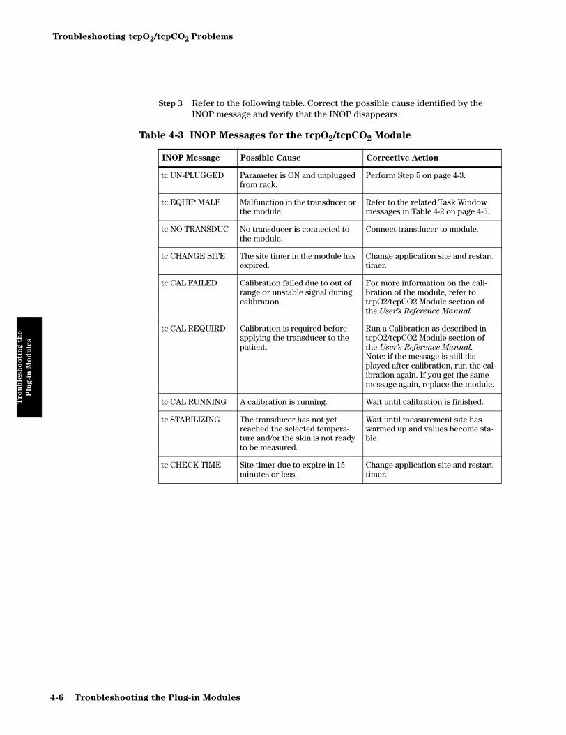
Troubleshooting tcpO2/tcpCO2 Problems
Tro
ub
lesh
oo
tin
g t
he
Plu
g-i
n M
od
ule
s
Step 3 Refer to the following table. Correct the possible cause identified by the INOP message and verify that the INOP disappears.
Table 4-3 INOP Messages for the tcpO2/tcpCO2 Module
INOP Message Possible Cause Corrective Action
tc UN-PLUGGED Parameter is ON and unplugged from rack.
Perform Step 5 on page 4-3.
tc EQUIP MALF Malfunction in the transducer or the module.
Refer to the related Task Window messages in Table 4-2 on page 4-5.
tc NO TRANSDUC No transducer is connected to the module.
Connect transducer to module.
tc CHANGE SITE The site timer in the module has expired.
Change application site and restart timer.
tc CAL FAILED Calibration failed due to out of range or unstable signal during calibration.
For more information on the cali-bration of the module, refer to tcpO2/tcpCO2 Module section of the User’s Reference Manual
tc CAL REQUIRD Calibration is required before applying the transducer to the patient.
Run a Calibration as described in tcpO2/tcpCO2 Module section of the User’s Reference Manual.
Note: if the message is still dis-played after calibration, run the cal-ibration again. If you get the same message again, replace the module.
tc CAL RUNNING A calibration is running. Wait until calibration is finished.
tc STABILIZING The transducer has not yet reached the selected tempera-ture and/or the skin is not ready to be measured.
Wait until measurement site has warmed up and values become sta-ble.
tc CHECK TIME Site timer due to expire in 15 minutes or less.
Change application site and restart timer.
4-6 Troubleshooting the Plug-in Modules
Troubleshooting tcpO2/tcpCO2 Problems
Tro
ub
lesh
oo
tin
g t
he
Plu
g-i
n M
od
ule
s
If tcpO2/tcpCO2 readings are questionable, perform the following actions:
Perform a tcpO2 zero check and tcpCO2 gain check for the transducer. These checks tell you whether the tcpO2/tcpCO2 transducer is working correctly.
Test Equipment
The following list gives you the test equipment recommended to perform the specification test on the tcpO2/tcpCO2 plug-in:
• 1 Calibration Unit (Philips 15210B or Radiometer TCC3)
• 1 Calibration gas bottle of Cal 1 gas (20.9% O2, 5% CO2) (see Chapter 6 “Parts List for CMS”)
• 1 Calibration gas bottle of Cal 2 gas (0% O2, 10% CO2) (see Chapter 6 “Parts List for CMS”)
• 1 Accessory Kit (15209-60010)
• 1 tcpO2/CO2 transducer (Philips M1918A or Radiometer transducer)
• 1 Calibration Tubing (M2205A)
Procedure
Step 1 Ensure correct function of the Calibration Unit (See “Gas Flow Performance Check” on page C-6 for Philips 15210B and Radiometer Service Documentation for Radiometer calibration unit TCC3).
Step 2 Make sure that you are not in Service mode.
Step 3 Set the transducer temperature to 43.0o C.
Step 4 Using a calibration unit (Philips M1918A or Radiometer calibration unit TCC3) and Cal 1 gas, calibrate the module as described in the tcpO2/tcpCO2 Module section of the User’s Reference Manual.
Step 5 Check and note down the displayed values for tcpO2 and tcpCO2. The values should not fluctuate more than 2 mmHg (0.3kPa) in 30 seconds.
Step 6 If the readings fluctuate more than 2 mmHg (0.3kPa), re-membrane the trans-ducer ensuring that the old electrolyte is thoroughly removed and check wether you need to activate the transducer. The tcpO2/tcpCO2 Module section of the User’s Reference Manual tells you how to do this.
Step 7 Repeat steps 4 and 5. If the test fails again, the transducer has unacceptable drift and has to be replaced. Repeat steps 4 and 5 with new transducer.
Troubleshooting the Plug-in Modules 4-7

Troubleshooting tcpO2/tcpCO2 Problems
Tro
ub
lesh
oo
tin
g t
he
Plu
g-i
n M
od
ule
s
Step 8 Replace the Cal 1 gas cylinder on the calibration unit with the Cal 2 gas cylinder. Turn on the gas supply of your calibration unit.
Step 9 Check the values displayed on the screen. The displayed tcpO2 must be < 6 mmHg (0.8kPa) within 10 minutes. The displayed tcpCO2 value must be within the range listed in the table within 10 minutes. If the tcpO2 is not < 6 mmHg (0.8kPa), and/or tcpCO2 values are not within the acceptance range listed in the tables given, the transducer does not measure correctly and needs to be replaced.
Table 4-4 Calibration Values
tcpCO2 at CAL1 gas Min. tcpCO2 at CAL2
gas Max. tcpCO2 at CAL2 gas
39 mmHg 5.2 kPa 74 mmHg 9.9 kPa 88 mmHg 11.7 kPa
38 mmHg 5.1 kPa 72 mmHg 9.7 kPa 86 mmHg 11.5 kPa
37 mmHg 5.0 kPa 70 mmHg 9.5 kPa 84 mmHg 11.3 kPa
36 mmHg 4.9 kPa 68 mmHg 9.3 kPa 81 mmHg 11.1 kPa
35 mmHg 4.8 kPa 66 mmHg 9.1 kPa 79 mmHg 10.8 kPa
34 mmHg 4.7 kPa 64 mmHg 8.9 kPa 77 mmHg 10.6 kPa
33 mmHg 4.6 kPa 62 mmHg 8.7 kPa 75 mmHg 10.4 kPa
32 mmHg 4.5 kPa 60 mmHg 8.5 kPa 72 mmHg 10.2 kPa
31 mmHg 4.4 kPa 59 mmHg 8.3 kPa 70 mmHg 9.9 kPa
30 mmHg 4.3 kPa 57 mmHg 8.1 kPa 68 mmHg 9.7 kPa
29 mmHg 4.2 kPa 55 mmHg 7.9 kPa 66 mmHg 9.5 kPa
28 mmHg 4.1 kPa 53 mmHg 7.7 kPa 63 mmHg 9.3 kPa
27 mmHg 4.0 kPa 51 mmHg 7.5 kPa 61 mmHg 9.1 kPa
26 mmHg 3.9 kPa 49 mmHg 7.4 kPa 59 mmHg 8.8 kPa
25 mmHg 3.8 kPa 47 mmHg 7.2 kPa 57 mmHg 8.6 kPa
24 mmHg 3.7 kPa 45 mmHg 7.0 kPa 55 mmHg 8.4 kPa
23 mmHg 3.6 kPa 43 mmHg 6.8 kPa 52 mmHg 8.2 kPa
22 mmHg 3.5 kPa 41 mmHg 6.6 kPa 50 mmHg 7.9 kPa
21 mmHg 3.4 kPa 39 mmHg 6.4 kPa 48 mmHg 7.7 kPa
20 mmHg 3.3 kPa 37 mmHg 6.2 kPa 46 mmHg 7.5 kPa
19 mmHg 3.2 kPa 35 mmHg 6.0 kPa 43 mmHg 7.3 kPa
4-8 Troubleshooting the Plug-in Modules

Troubleshooting ECG and ECG/RESP Problems
Tro
ub
lesh
oo
tin
g t
he
Plu
g-i
n M
od
ule
s
Troubleshooting ECG and ECG/RESP Problems
This section describes how to troubleshoot and correct faults associated with the ECG/RESP module. The procedures for recognizing, isolating, and correcting faults using this module are as follows:
• Identifying a problem based on visual indications or repeated INOPS.
To Troubleshoot the Module
If neither numerics nor a -?- are displayed for the ECG/RESP module, perform the following actions:
Step 1 Make sure there is a trunk cable with lead set connected to the module. If not, connect one.
Step 2 Make sure the ECG and RESP parameters are turned on. If they are not, turn them on.
Step 3 Make sure the ECG (HR) and RESP numerics are turned on. If they are not, turn them on.
Step 4 Make sure you don’t have more than one ECG/RESP module plugged into the module racks you are using. If more than one ECG/RESP module is plugged in, the supernumerary modules are ignored and should be removed.
Step 5 Check the connection on the module and the rack interface.
1. Unplug and re-plug the ECG/RESP module and check if the green LED on the ECG/RESP module lights up after re-plugging. If it does not, proceed with the following:
2. Put the ECG/RESP module into another slot and check the LED once again. If it lights up now, the connector for the previous slot is faulty and the rack needs to be replaced. If it does not, proceed with the following:
3. Note: this procedure applies only for setups, in which the ECG/RESP
module is located in a Satellite Rack. If this does not apply for your
situation, proceed with 4.
Replace the cable from the Satellite Rack to the function box. Again unplug and re-plug the ECG/RESP module and check if the LED lights up. If it does not, proceed with the following:
4. Plug any other (not faulty) module into the same slot and check if the LED lights up. If the LED of the alternative module lights up, the ECG/RESP module is defect and has to be replaced. If it does not, either the rack or the rack interface card is defect. Proceed with the following:
5. Replace the rack and plug in the ECG/RESP module into the new rack. If the LED on the module does not light up, replace the rack interface card in the function box.
Troubleshooting the Plug-in Modules 4-9

Troubleshooting ECG and ECG/RESP Problems
Tro
ub
lesh
oo
tin
g t
he
Plu
g-i
n M
od
ule
s
If a -?- instead of a numeric and one or more INOP messages are displayed for the ECG/RESP module, perform the following actions:
Please note that for proceeding to the next steps a trunk cable with lead set must be
connected to the module.
Step 1 Perform a module self-test (See “Performing the ECG or ECG/RESP Module Self-Test” on page 4-57). If the ECG/RESP test numerics read exactly the listed values, proceed to the next step, if not, replace the module.
Step 2 Refer to the following table. Correct the possible cause identified by the INOP message and verify that the INOP disappears. If the problem still exists, replace the module.
Table 4-5 INOP Messages for ECG and ECG/Resp
INOP Message Possible Cause Corrective Action
LEADS OFF Not all required leads are attached or electrodes have been displaced.With activated EASITM option the wrong lead set is used.Lead set or ECG Module may be defective.
Make sure all electrodes are cor-rectly attached.With activated EASITM option make sure you are using the cor-rect (5 electrode) lead set.If INOP still is displayed, change lead set.If INOP persists, replace module.
LEADS OFF XX Single electrode from lead xx detached.
Attach the missing electrode. If INOP still is displayed, see Cor-rective Action for “LEADS OFF”
LEADS OFF (EL.X) Single electrode from lead E,S or I is detached (EASITMlead set).
Attach the missing electrode. If INOP still is displayed, see Cor-rective Action for “LEADS OFF”
ECG/RESP UNPLUGGED
ECG/RESP module is unplugged from the rack.
Perform Step 5 on page 4-9.
ECG EQUIP MALF Malfunction in ECG hardware. Replace module.
ECG/RESP UNPLUGGED
ECG/RESP module is unplugged from the rack.
Perform Step 5 on page 4-9.
RESP LEAD OFF RESP lead is off, electrode detached, or patient cable unplugged.
Make sure all electrodes are cor-rectly attached.If INOP still is displayed, change lead set.If INOP persists, replace module.
RESP EQUIP MALF Malfunction in RESP hardware. Replace module.
4-10 Troubleshooting the Plug-in Modules

Troubleshooting Pressure Problems
Tro
ub
lesh
oo
tin
g t
he
Plu
g-i
n M
od
ule
s
Troubleshooting Pressure Problems
This section describes how to troubleshoot and correct faults associated with the M1006A and M1006B Pressure plug-in modules. The procedures for recognizing, isolating, and correcting faults with this module are as follows:
• Identifying a problem based on visual indications or repeated INOPS.
To Troubleshoot the Module
If neither numerics nor a -?- are displayed for the PRESSURE module, perform the following actions:
Step 1 Make sure there is a transducer connected to the module. If no transducer is connected, connect one.
Step 2 Make sure the PRESSURE parameter is turned on. Turn it on, if it is not.
Step 3 Make sure the PRESSURE numeric is turned on. Turn it on, if it is not.
Step 4 If you want to measure CPP, make sure that one PRESSURE parameter is labeled ICP and both pressures display valid numerics.
Step 5 Make sure you don’t have too many PRESSURE module plugged into the module racks you are using. If too many PRESSURE modules are plugged in, you get two status messages: “Too many modules of the same type connected” and “Currently ignored module in rack position x.x”. The last message enables you to identify the supernumerary module.These modules are ignored and should be removed. See Appendix A “Product Information” for specific information concerning your model of the CMS.
Step 6 Check the connection on the module and the rack interface.
1. Unplug and re-plug the PRESSURE module and check if the green LED on the PRESSURE module lights up after re-plugging. If it does not, proceed with the following:
2. Put the PRESSURE module into another slot and check the LED once again. If it lights up now, the connector for the previous slot is faulty and the rack needs to be replaced. If it does not, proceed with the following:
3. Note: this procedure applies only for setups, in which the PRESSURE
module is located in a Satellite Rack. If this does not apply for your
situation, proceed with 4.
Replace the cable from the Satellite Rack to the function box. Again unplug and re-plug the PRESSURE module and check if the LED lights up. If it does not, proceed with the following:
4. Plug any other (not faulty) module into the same slot and check if the LED lights up. If the LED of the alternative module lights up, the
Troubleshooting the Plug-in Modules 4-11

Troubleshooting Pressure Problems
Tro
ub
lesh
oo
tin
g t
he
Plu
g-i
n M
od
ule
s
PRESSURE module is defect and has to be replaced. If it does not, either the rack or the rack interface card is defect. Proceed with the following:
5. Replace the rack and plug in the PRESSURE module into the new rack. If the LED on the module does not light up, replace the rack interface card in the function box.
If a -?- instead of a numeric and one or more INOP messages are displayed for the PRESSURE module, perform the following actions:
Please note that for proceeding to the next steps a transducer must be connected to
the module.
Step 1 Perform a module self-test (See “Performing the M1006A/B Pressure Module Self-Test” on page 4-57). If the PRESSURE test numerics read exactly the listed values, proceed to the next step, if not, replace the module.
Step 2 Refer to the following table. Correct the possible cause identified by the INOP message and verify that the INOP disappears. If the problem still exists, replace the module.
Table 4-6 INOP Messages for Pressure
INOP Message Possible Cause Corrective Action
<Px> UNPLUGGED Pressure module is unplugged from the rack.
Perform Step 6 on page 4-11.
<Px> NO TRANSDUCER No transducer connected to the module.
Connect transducer to module.
<Px> EQUIP MALF Malfunction in the pres-sure hardware.
Replace module.
<Px> ZERO + CHECK CAL Occurs when new trans-ducer attached to mod-ule, or when the power is off for longer than one minute and settings trans-fer is off.
Zero the PRESSURE module.
<Px> OVERRANGE Measured pressure >361 mmHg, <-41 mmHg.
Replace transducer. If the INOP persists, replace module.
CPP CHECK SOURCES Occurs for one minute if either the arterial or the intracranial pressure sources are switched off, or the front end modules are removed.
Connect module properly to rack and make sure that the PRESSURE parameter is turned on.Make sure you get valid numerics for ICP and the other pressure. Make sure that the preselected pressure label in the CPP source window is the same as for the second pressure.
CPP CHECK UNITS Occurs if two pressure sources have different units.
Use the same unit for all PRESSURE modules.
4-12 Troubleshooting the Plug-in Modules

Troubleshooting NBP Problems
Tro
ub
lesh
oo
tin
g t
he
Plu
g-i
n M
od
ule
s
Troubleshooting NBP Problems
To ensure accurate NIBP measurements, the NBP plug-in module can be calibrated. Philips recommends that the module is calibrated once every 12 months.
This section describes how to troubleshoot and correct faults associated with the NBP module. The procedures for recognizing, isolating, and correcting faults with this module are as follows:
• Identifying a problem based on visual indications or repeated INOPS.
• Checking the NBP task window for specific error messages and performing the corrective actions suggested in the table given with this module.
• Calibrating the module as required.
To Troubleshoot the Module
If neither numerics nor a -?- are displayed for the NBP module, perform the following actions:
Step 1 Make sure the NBP parameter is turned on. Turn it on, if it is not.
Step 2 Make sure the NBP numeric is turned on. Turn it on, if it is not.
Step 3 Make sure you don’t have more than one NBP module plugged into the module racks you are using. If more than one NBP module is plugged in, the supernumerary modules are ignored and should be removed.
Step 4 Check the connection on the module and the rack interface.
1. Unplug and re-plug the NBP module and check if the green LED on the NBP module lights up after re-plugging. If it does not, proceed with the following:
2. Put the NBP module into another slot and check the LED once again. If it lights up now, the connector for the previous slot is faulty and the rack needs to be replaced. If it does not, proceed with the following:
3. Note: this procedure applies only for setups, in which the NBP module
is located in a Satellite Rack. If this does not apply for your situation,
proceed with 4.
Replace the cable from the Satellite Rack to the function box. Again unplug and re-plug the NBP module and check if the LED lights up. If it does not, proceed with the following:
Philips uses
invasive pressure
as reference for
NBP. Diastolic
measurements
can be up to 8
mmHg lower
than pressure
measured by
auscultatory
(Korotkoff)
method.
Troubleshooting the Plug-in Modules 4-13

Troubleshooting NBP Problems
Tro
ub
lesh
oo
tin
g t
he
Plu
g-i
n M
od
ule
s
4. Plug any other (not faulty) module into the same slot and check if the LED lights up. If the LED of the alternative module lights up, the NBP module is defect and has to be replaced. If it does not, either the rack or the rack interface card is defect. Proceed with the following:
5. Replace the rack and plug in the NBP module into the new rack. If the LED on the module does not light up, replace the rack interface card in the function box.
If a -?- instead of a numeric and one or more INOP messages are displayed for the NBP module, perform the following actions:
Step 1 Refer to the following table. Correct the possible cause identified by the INOP message and verify that the INOP disappears. If the problem still exists, replace the module.
Table 4-7 INOP Messages for the NBP Module
INOP Message Possible Cause Corrective Action
NBP UNPLUGGED NBP is unplugged from rack.
Perform Step 4 on page 4-13.
NBP EQUIP MALF Hardware problem in module or tubing.
Exchange the tubing and restart measure-ment.If the INOP reoccurs and the message in the NBP task window reads “Pressure values of transducers different”, attempt a calibration (See “Performance Test NBP Module” on page 2-6). If this fails, replace the module.
NBP INTERRUPTED Strong patient move-ment or
Inflation/deflation time-out – pump problem.
Make sure the patient does not move strongly and restart measurement.
Check wether cuff is connected. Check tubing and cuff for leakages and restart measurement.
NBP CUFF OVER-PRESS
Strong patient move-ment or defect in pneumatic control.
Restart measurement making sure that patient does not move strongly. If INOP reoccurs, replace module.
NBP INCORRECT CUFF
Neonatal cuff used for adult patient size set-ting.
Make sure the patient size configuration is set to PEDI/NEO and restart measure-ment.
CUF NOT DEFLATED
Hardware problem in module or tubing.
Exchange the tubing and restart measure-ment.If the INOP reoccurs, replace module.
4-14 Troubleshooting the Plug-in Modules

Troubleshooting NBP Problems
Tro
ub
lesh
oo
tin
g t
he
Plu
g-i
n M
od
ule
s
Using the Calibration Mode
This task window is displayed after pressing the softkey in the NBP manometer task window.
The keys , , and are displayed at the bottom of the Calibration Mode Task Window. The key is used to close the valves, the key opens the valves and the key is used to store the calibration factor.
Step 1 Press .
Step 2 Pressurize the gauge as precisely as possible to 220 or 280 mmHg. One of these val-ues (depending on the module) is shown in the NBP manometer task window.
Step 3 Now press one of the following keys:: to store the calibration factor.
or : to abandon the calibration procedure.
Selecting NBP Measurement Characteristic
WARNING Consult technical support before changing the NBP measurement characteristic
in adult or pediatric mode. Changing the NBP measurement characteristic will
significantly change the NBP readings, especially in the elevated pressure range.
WARNING The NBP measurement characteristic has to be set and stored individually for
each configuration set. The same setting must be selected for all configuration
sets.
NOTE This setting changes the NBP measurement characteristic in adult and pediatric mode. It has no influence on the NBP measurement characteristic in neonatal mode. In neonatal mode the intra-arterial method is always used as a reference standard to validate overall accuracy.
1.Go into service mode
2. Enter the NBP Task Window and press the ‘Change Refernce” key
3. Select desired NBP measurement characteristic (1, 2, or 3) according to the table below
4. Press “Confirm” to store new setting
5.Go into Config mode and select next Config Set
6.Repeat Steps 1 to 5 for all Config Sets
Cal Frontend
Start Stop Save ValuesStart Stop
Save Values
Start
Save Values
Stop
Troubleshooting the Plug-in Modules 4-15

Troubleshooting NBP Problems
Tro
ub
lesh
oo
tin
g t
he
Plu
g-i
n M
od
ule
s
The setting of NBP measurement characteristic is stored in the monitor and can be cloned with the cloning tool.
Selection Description Reference Standard for Validation
1 NBP measurement characteristic of CMS/V24/
V26 Rel. B.0 and earlier. Recommended only in mixed installations with Rel. B.0 or
earlier.
Intra-arterial according to ANSI/AAMI SP10-1987.The blood pressure measurements determined with this device and measurement characteristic set to “1” comply
with the American National Standard for Electronic or Automated Sphygmomanometers (ANSI/AAMI SP-10-
1987) in relation to mean error and standard deviation, when compared to intra-arterial measurements in a
representative patient population.
2 NBP measurement characteristic of M3/M4 Rel.
B and earlier (higher diastolic values than 1).
Recommended if customer prefers calibration against
manual auscultatory reference method.
Auscultatory according to ANSI/AAMI SP10-1992. The blood pressure measurements determined with this
device and measurement characteristic set to “2” comply with the American National Standard for Electronic or Automated Sphygmomanometers (ANSI/AAMI SP-10-
1992) in relation to mean error and standard deviation, when compared to auscultatory measurements in a
representative patient population. For the auscultatory reference the 5th Korotkoff sound was used to determine
the diastolic pressure.
3 (Factory Default)
NBP measurement characteristic of CMS/V24/
V26 Rel. C.0 and laterRecommended in all other
cases than described above.
Intra-arterial according to ANSI/AAMI-SP10-1992.The blood pressure measurements determined with this device and measurement characteristic set to “3” comply
with the American National Standard for Electronic or Automated Sphygmomanometers (ANSI/AAMI SP10-
1992) in relation to mean error and standard deviation, when compared to intra-arterial measurements in a
representative patient population.
4-16 Troubleshooting the Plug-in Modules

Troubleshooting Cardiac Output Problems
Tro
ub
lesh
oo
tin
g t
he
Plu
g-i
n M
od
ule
s
Troubleshooting Cardiac Output Problems
This section describes how to troubleshoot and correct faults associated with the Cardiac Output plug-in module. The procedures for recognizing, isolating, and correcting faults with this module are as follows:
• Identifying a problem based on visual indications or repeated INOPS.
To Troubleshoot the Module
If neither numerics nor a -?- are displayed for the C.O. module, perform the following actions:
Step 1 Make sure there is a C.O. Interface Cable and a catheter connected to the module. If not, connect them.
Step 2 Make sure the C.O. parameter is turned on. Turn it on, if it is not.
Step 3 Make sure the C.O. numeric is turned on. Turn it on, if it is not.
Step 4 Make sure you don’t have more than one C.O. module plugged into the module racks you are using. If more than one C.O. module is plugged in, the supernumerary modules are ignored and should be removed.
Step 5 Check the connection on the module and the rack interface.
1. Unplug and re-plug the C.O. module and check if the green LED on the C.O. module lights up after re-plugging. If it does not, proceed with the following:
2. Put the C.O. module into another slot and check the LED once again. If it lights up now, the connector for the previous slot is faulty and the rack needs to be replaced. If it does not, proceed with the following:
3. Note: this procedure applies only for setups, in which the CO module is
located in a Satellite Rack. If this does not apply for your situation,
proceed with 4.
Replace the cable from the Satellite Rack to the function box. Again unplug and re-plug the CO module and check if the LED lights up. If it does not, proceed with the following:
4. Plug any other (not faulty) module into the same slot and check if the LED lights up. If the LED of the alternative module lights up, the C.O. module is defect and has to be replaced. If it does not, either the rack or the rack interface card is defect. Proceed with the following:
5. Replace the rack and plug in the C.O. module into the new rack. If the LED on the module does not light up, replace the rack interface card in the function box.
Troubleshooting the Plug-in Modules 4-17
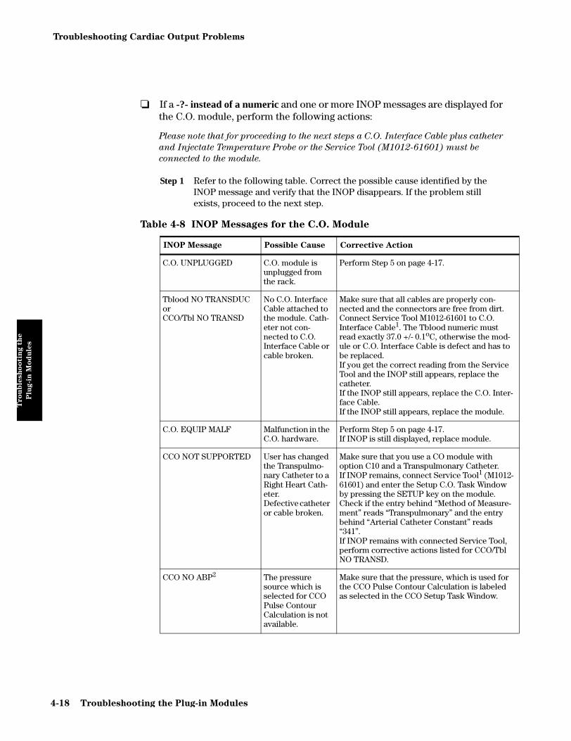
Troubleshooting Cardiac Output Problems
Tro
ub
lesh
oo
tin
g t
he
Plu
g-i
n M
od
ule
s
If a -?- instead of a numeric and one or more INOP messages are displayed for the C.O. module, perform the following actions:
Please note that for proceeding to the next steps a C.O. Interface Cable plus catheter
and Injectate Temperature Probe or the Service Tool (M1012-61601) must be
connected to the module.
Step 1 Refer to the following table. Correct the possible cause identified by the INOP message and verify that the INOP disappears. If the problem still exists, proceed to the next step.
Table 4-8 INOP Messages for the C.O. Module
INOP Message Possible Cause Corrective Action
C.O. UNPLUGGED C.O. module is unplugged from the rack.
Perform Step 5 on page 4-17.
Tblood NO TRANSDUCorCCO/Tbl NO TRANSD
No C.O. Interface Cable attached to the module. Cath-eter not con-nected to C.O. Interface Cable or cable broken.
Make sure that all cables are properly con-nected and the connectors are free from dirt.Connect Service Tool M1012-61601 to C.O. Interface Cable1. The Tblood numeric must read exactly 37.0 +/- 0.1oC, otherwise the mod-ule or C.O. Interface Cable is defect and has to be replaced. If you get the correct reading from the Service Tool and the INOP still appears, replace the catheter.If the INOP still appears, replace the C.O. Inter-face Cable.If the INOP still appears, replace the module.
C.O. EQUIP MALF Malfunction in the C.O. hardware.
Perform Step 5 on page 4-17.If INOP is still displayed, replace module.
CCO NOT SUPPORTED User has changed the Transpulmo-nary Catheter to a Right Heart Cath-eter.Defective catheter or cable broken.
Make sure that you use a CO module with option C10 and a Transpulmonary Catheter.If INOP remains, connect Service Tool1 (M1012-61601) and enter the Setup C.O. Task Window by pressing the SETUP key on the module.Check if the entry behind “Method of Measure-ment” reads “Transpulmonary” and the entry behind “Arterial Catheter Constant” reads “341”.If INOP remains with connected Service Tool, perform corrective actions listed for CCO/Tbl NO TRANSD.
CCO NO ABP2 The pressure source which is selected for CCO Pulse Contour Calculation is not available.
Make sure that the pressure, which is used for the CCO Pulse Contour Calculation is labeled as selected in the CCO Setup Task Window.
4-18 Troubleshooting the Plug-in Modules

Troubleshooting Cardiac Output Problems
Tro
ub
lesh
oo
tin
g t
he
Plu
g-i
n M
od
ule
s
Step 2 Enter the Measure C.O. Task Window by pressing the START key on the C.O. module. The Measure C.O. Task Window displays messages dealing with C.O. module failures. The following table describes the messages and corrective actions to take.
CCO ABPa INVALID The pressure for CCO Pulse Con-tour Calculation is not valid.
Make sure you get valid numerics for ABPa. For more information refer to the Pressure Module section in the User’s Reference Manual.
CCO NO CAL. No valid calibra-tion for CCO.
Perform C.O. measurement and CCO calibra-tion.
CCO BAD PRESS SIGN The pressure wave for CCO Pulse Contour cal-culation cannot be analyzed.
Make sure to get a proper, undamped pressure wave. For more information refer to the C.O. Module section in the User’s Reference Manual.
1. For correct use of the Service Tool, see “Performance Test Cardiac Output” onpage 2-8
2. ABP is only a placeholder. Always the selected pressure label is shown in the string.
Table 4-9 Task Window messages for the C.O. Module
Task Window
Message
Possible
CauseCorrective Action
no Tinj transducer connected
Cable of Injec-tate Tempera-ture Probe is not connected or broken.Faulty module.
Make sure that cable of the Injectate Temperature Probe is properly connected to the C.O. Interface Cable and the connector is free from dirt.
Connect Service Tool M1012-61601 to C.O. Interface Cable1.
If you use the C.O. module without option C10 you must get the following results, otherwise the module or C.O. Interface Cable are defect and have to be replaced:• Tinj numeric reads exactly 0.0oC• No prompt message “Tinj transducer connected”
appears in the Measure C.O. Task Window.
If you use the C.O. module with option C10 you must get the following results, otherwise the module or C.O. Interface Cable are defect and have to be replaced:• No prompt message “Tinj transducer connected”
appears in the Measure C.O. Task Window.
If you get the correct results from the Service Tool and the Task Window message still appears, replace the Injectate Temperature Probe.
Table 4-8 INOP Messages for the C.O. Module
INOP Message Possible Cause Corrective Action
Troubleshooting the Plug-in Modules 4-19

Troubleshooting Cardiac Output Problems
Tro
ub
lesh
oo
tin
g t
he
Plu
g-i
n M
od
ule
s
Unexpected cath-eter, check cathe-ter constant2
The C.O. mod-ule is not able to identify the Transpulmo-nary Catheter type.Faulty C.O. Interface Cable, module or cath-eter.
Note: the following procedure applies only for C.O.
modules with option C10:
Make sure that catheter and C.O. Interface Cable are properly connected and the connector is free from dirt.Connect Service Tool M1012-61601 to C.O. module1 and enter the Setup C.O. Task Window by pressing the SETUP key on the module. The entry behind “Method of Measurement” must read “Transpulmonary”. The entry behind “Arterial Cathe-ter Constant” must read “341”. If you don’t get these results, replace the C.O. Inter-face Cable and check the readings again. If they are still wrong, the module is defect and has to be replaced.
If you get the correct results from the Service Tool and the Task Window message still appears, replace the catheter.
Unknown cathe-ter
Faulty C.O. Interface Cable, module or cath-eter.
Make sure that catheter and C.O. Interface Cable are properly connected and the connector is free from dirt.Connect Service Tool M1012-61601 to C.O. module1.If Task Window message now has disappeared, replace catheter.If Task Window message still appears, replace C.O. Interface Cable.If Task Window message still appears, replace module.
1. For correct use of the Service Tool, see “Performance Test Cardiac Output” onpage 2-8
2. #C10 modules only
Table 4-9 Task Window messages for the C.O. Module
Task Window
Message
Possible
CauseCorrective Action
4-20 Troubleshooting the Plug-in Modules

Troubleshooting Cardiac Output Problems
Tro
ub
lesh
oo
tin
g t
he
Plu
g-i
n M
od
ule
s
If a small -?- in addition to a numeric and one or more INOP messages are displayed for the C.O. module, the values are questionable. Correct the possible cause identified by the INOP message and verify that the INOP disappears.
Table 4-10 INOP Messages with questionable values for the C.O. Module
INOP Message Possible Cause Corrective Action
CCO CHECK CAL CCO calibration is older than 8 hours.
Perform C.O. measurement and CCO calibration.
SVR MISSING CVP
No valid CVP available at the moment. CVP is automatically set to 0 mmHg for the continu-ous SVR calcula-tion
If you need an accurate continuous SVR measure-ment, perform a CVP measurement and make sure that the pressure which is used for the CVP mea-surement is labeled “CVP”.Make sure you get valid numerics for CVP.For more information refer to the Pressure Module section in the User’s Reference Manual.
Troubleshooting the Plug-in Modules 4-21

Troubleshooting SpO2/Pleth Problems
Tro
ub
lesh
oo
tin
g t
he
Plu
g-i
n M
od
ule
s
Troubleshooting SpO2/Pleth Problems
This section describes how to troubleshoot and correct faults associated with the SpO2/Pleth plug-in module. The procedures for recognizing, isolating, and correcting faults with this module are as follows:
• Identifying a problem based on visual indications or repeated INOPS.
To Troubleshoot the Module
If neither numerics nor a -?- are displayed for the SpO2/Pleth module, perform the following actions:
Step 1 Make sure there is a transducer connected to the module. If no transducer is connected, connect one.
Step 2 Make sure the SpO2/Pleth parameter is turned on. Turn it on, if it is not.
Step 3 Make sure the SpO2/Pleth numeric is turned on. Turn it on, if it is not.
Step 4 Make sure you don’t have too many SpO2/Pleth module plugged into the module racks you are using. If too many SpO2/Pleth modules are plugged in, you get two status messages: “Too many modules of the same type connected” and “Currently ignored module in rack position x.x”. The last message enables you to identify the supernumerary module.These modules are ignored and should be removed. See Appendix A “Product Information” for specific information concerning your model of the CMS.
Step 5 Check the connection on the module and the rack interface.
1. Unplug and re-plug the SpO2/Pleth module and check if the green LED on the SpO2/Pleth module lights up after re-plugging. If it does not, proceed with the following:
2. Put the SpO2/Pleth module into another slot and check the LED once again. If it lights up now, the connector for the previous slot is faulty and the rack needs to be replaced. If it does not, proceed with the following:
3. Note: this procedure applies only for setups, in which the SpO2/
PlethSpO2/Pleth module is located in a Satellite Rack. If this does not
apply for your situation, proceed with 4.
Replace the cable from the Satellite Rack to the function box. Again unplug and re-plug the SpO2/Pleth module and check if the LED lights up. If it does not, proceed with the following:
4. Plug any other (not faulty) module into the same slot and check if the LED lights up. If the LED of the alternative module lights up, the SpO2/Pleth module is defect and has to be replaced. If it does not, either the rack or the rack interface card is defect. Proceed with the following:
4-22 Troubleshooting the Plug-in Modules

Troubleshooting SpO2/Pleth Problems
Tro
ub
lesh
oo
tin
g t
he
Plu
g-i
n M
od
ule
s
5. Replace the rack and plug in the SpO2/Pleth module into the new rack. If the LED on the module does not light up, replace the rack interface card in the function box.
If a -?- instead of a numeric and one or more INOP messages are displayed for the SpO2/Pleth module, perform the following actions:
Please note that for proceeding to the next steps a transducer must be connected to
the module.
Step 1 Perform a Self-Test (See “Performing the SpO2/Pleth Module Self-Test” on page 4-58). If the SpO2/Pleth test numerics read exactly the listed values, proceed to the next step, if not, replace the module.
Step 2 Refer to the following table. Correct the possible cause identified by the INOP message and verify that the INOP disappears. If the problem still exists, replace the module.
Table 4-11 INOP Messages for the SpO2/Pleth Module
INOP Message Possible Cause Corrective Action
SpO2 /PLETH NO TRANSDUCER
No transducer is connected to the module
Connect transducer to module.
SpO2 /PLETH EQUIP MALF
Malfunction in the transducer or module.
Replace transducer. If INOP persists, replace module
SpO2 /PLETH UNPLUGGED
SpO2 /PLETH module is unplugged from the rack.
Perform Step 5 on page 4-22
SpO2 ERRATIC Erratic SpO2 measurements, often due to a faulty transducer, or invalid SpO2 measurements; often due to the transducer being incorrectly positioned.
Reposition transducer. If the INOP persists, replace transducer.
SpO2/PLETH NOISY SIGNAL
Patient movement or electrical interference are causing irregu-lar pulse patterns.
Make sure that patient does not move strongly. If INOP persists, move cable away from power cords.
SpO2/PLETH INTERF
Level of ambient light and/or cable induced electrical inter-ference is so high, that the SpO2 transducer cannot measure pulse rate.
Cover transducer against ambient light and move cable away from power cords.
SpO2/PLETH NON-PULSATILE
Pulse is too weak or not detect-able.
Move transducer to another applica-tion site.
PLETHREDUCE SIZE
Transducer displaced or strong vasodilation after automatic wave fixing.
Press Optimize Size softkey in PLETH Task Window to restore the PLETH wave.
SpO2 TRANSD MALF orPLETH TRANSD MALF
SpO2 transducer is defective due to inadequate diode output.
Replace the transducer.
Troubleshooting the Plug-in Modules 4-23

Troubleshooting SvO2 Problems
Tro
ub
lesh
oo
tin
g t
he
Plu
g-i
n M
od
ule
s
Troubleshooting SvO2 Problems
This section describes how to troubleshoot and correct faults associated with the SvO2
plug-in module. The procedures for recognizing, isolating, and correcting faults with this module are as follows:
• Identifying a problem based on visual indications or repeated INOPS.
To Troubleshoot the Module
If neither numerics nor a -?- are displayed for the SvO2 module, perform the following actions:
Step 1 Make sure there is a Abbott optical module and catheter connected to the module. If not, connect one.
Step 2 Make sure the SvO2 parameter is turned on. Turn it on, if it is not.
Step 3 Make sure the SvO2 numeric is turned on. Turn it on, if it is not.
Step 4 Make sure you don’t have more than one SvO2 module plugged into the module racks you are using. If more than one SvO2 module is plugged in, the supernumerary modules are ignored and should be removed.
Step 5 Check the connection on the module and the rack interface.
1. Unplug and re-plug the SvO2 module and check if the green LED on the SvO2 module lights up after re-plugging. If it does not, proceed with the following:
2. Put the SvO2 module into another slot and check the LED once again. If it lights up now, the connector for the previous slot is faulty and the rack needs to be replaced. If it does not, proceed with the following:
3. Note: this procedure applies only for setups, in which the SvO2 module
is located in a Satellite Rack. If this does not apply for your situation,
proceed with 4.
Replace the cable from the Satellite Rack to the function box. Again unplug and re-plug the SvO2 module and check if the LED lights up. If it does not, proceed with the following:
4. Plug any other (not faulty) module into the same slot and check if the LED lights up. If the LED of the alternative module lights up, the SvO2 module is defect and has to be replaced. If it does not, either the rack or the rack interface card is defect. Proceed with the following:
5. Replace the rack and plug in the SvO2 module into the new rack. If the LED on the module does not light up, replace the rack interface card in the function box.
4-24 Troubleshooting the Plug-in Modules

Troubleshooting SvO2 Problems
Tro
ub
lesh
oo
tin
g t
he
Plu
g-i
n M
od
ule
s
If a -?- instead of a numeric and one or more INOP messages are displayed for the SvO2 module, perform the following actions:
Please note that for proceeding to the next steps a Abbott optical module and
transducer must be connected to the module.
Step 1 Perform a Self-Test (See “Performing the SvO2 Module Self-Test” on page 4-60). If the SvO2 test numeric reads exactly the listed value, proceed to the next step, if not, replace the module.
Step 2 Refer to the following table. Correct the possible cause identified by the INOP message and verify that the INOP disappears. If the problem still exists, replace the module.
Table 4-12 INOP Messages for SvO2 Module
Symptom Possible Cause Corrective Action
SvO2 UNPLUGGED
SvO2 module is unplugged from the rack
Plug SvO2 module into rack.
SvO2 NO OPT-MOD
Abbott Optical Module not connected. Loose or broken connec-tion between Abbott Opti-cal Module and M1021A
Check set-up (described in Reference Man-ual).Replace Abbott Optical Module.
SvO2 CON-FIGURATION
Abbott Optical Module has been used with Abbott monitor (Oximetrix 3) and configured to SaO2 Compu-tation Mode.
Reconfigure the Abbott Optical Module to SvO2 Computation Module using the Abbott OximetrixR3 monitor.
SvO2 CAL REQUIRED
No valid calibration data in the Abbott Optical Module.
Perform Pre-insertion Calibration if the cathe-ter is still in the Optical Reference or In-Vivo Calibration if the catheter has been inserted into the patient.
SvO2 CONNCT OPTMOD
Abbott Optical Module became disconnected dur-ing storage of data.
Reconnect the Optical Module for at least 20 seconds.
SvO2 OPT-MOD DEFECT
Abbott Optical Module or M1021A memory defect - calibration and patient data cannot be stored for trans-port.
Try different Abbott Optical Module.If problem persists try different M1021A.
SvO2 EQUIP MALF
M1021A or Abbott Optical Module is defective.
Unplug Abbott Optical Module from M1021A and perform a self-test under the Monitor Setup Key. If INOP remains, replace the SvO2 module. If INOP disappears, replace Abbott Optical Module then consult local Abbott rep-resentative for information relating to the Abbott Optical Module.
Troubleshooting the Plug-in Modules 4-25

Troubleshooting SvO2 Problems
Tro
ub
lesh
oo
tin
g t
he
Plu
g-i
n M
od
ule
s
SvO2 WARM UP
Initial one minute Abbott Optical Module warm-up/connection period.
Inop is displayed for minimum time required. However, prior to performing Pre-Insertion or In-Vivo Calibration, Abbott recommends a full 15 minute warm-up period.
SvO2 LOW LIGHT
Unusually low level of light is being received by the sys-tem from the catheter due to:
Catheter tip or Abbott Opti-cal Module exposed to room light.Damaged catheter fiberop-tics.Poor catheter connection to Abbott Optical Module. Poor connection between Abbott Optical Module and M1021A.Defective Abbott Optical Module.Defective M1021A.
Check setup and connections. Ensure that fiber-optic interfaces of Abbott Optical Mod-ule and catheter are clean.If no catheter is connected to Abbott Optical Module, close Optical Module door and shield from room light. If message persists, try, in turn, different Optical Modules and M1021A to isolate the source.If catheter is connected to Abbott Optical Module and catheter tip has been removed from the Optical Reference but has not yet been inserted into the patient, the SvO2 LOW LIGHT INOP is displayed until the catheter is inserted into the patient.If catheter is still in tray, ensure that the cathe-ter tip is correctly positioned in the Optical Reference. If INOP persists, disconnect cathe-ter, close Abbott Optical Module door and shield from room light. If INOP disappears, try a different catheter. If INOP remains, either the optical Module or M1021A is at fault. Iso-late accordingly as above.If catheter is inserted into patient, review light intensity signals. Check catheter positioning, patency and catheter clamping to ensure opti-mal signal. If INOP persists, replace Abbott Optical Module (perform In-Vivo calibration if INOP disappears). If INOP still persists, replace catheter and recommence measure-ment procedure.
Table 4-12 INOP Messages for SvO2 Module
Symptom Possible Cause Corrective Action
4-26 Troubleshooting the Plug-in Modules

Troubleshooting SvO2 Problems
Tro
ub
lesh
oo
tin
g t
he
Plu
g-i
n M
od
ule
s
SvO2 LIGHT INTENS
Intensity changed consider-ably since last Light Inten-sity Calibration.
High Intensities:Catheter tip against vessel wall
Low Intensities:Damaged catheter
Inadequate blood flow past catheter tip.Poor optical interface between the catheter and Abbott Optical Module
Damped or Erratic Inten-
sities:Catheter tip clotting
Spontaneous catheter wedging.
Check Light Intensity trend using most detailed time frame.
Confirm proper catheter position by examina-tion of pressure waveforms.
Check for kinks in the catheter or excessive catheter clamping.Check for distal lumen patency.
Check for clean and secure connection.
Check pressure waveform for damping and ensure distal lumen patency.Check pressure waveform and ensure cathe-ter is correctly positioned.
After making all efforts to obtain a normal Light Intensity, perform a Light Intensity Cali-bration. (An In-Vivo Calibration may also be required.)Run a Calibration as described in SvO2 Mod-ule section of the User’s Reference Manual.
SvO2 CAL FAILED
Light Intensity signal drift has occurred after comple-tion of Pre-insertion Cali-bration and before insertion of catheter into patient.
Allow optimum warm-up time before any cali-bration procedure (minimum 15 minutes).If INOP appears prior to removing catheter tip from Optical Reference, repeat Pre-insertion Calibration.If INOP is noted after the catheter tip is removed from the Optical Reference, insert the catheter into patient, ensure optimal light intensity signal, then perform In-Vivo Calibra-tion.
SvO2 UNABLE TO MEASURE
Signal received is outside normal range such that SvO2 values cannot be derived.
Check for problems associated with LOW LIGHT or LIGHT INTENS INOPs.Check catheter position, patency and clamp-ing, ensure optimal Light Intensity signal and perform Light Intensity and In-Vivo Calibra-tions.
Table 4-12 INOP Messages for SvO2 Module
Symptom Possible Cause Corrective Action
Troubleshooting the Plug-in Modules 4-27

Troubleshooting FIO2 Module Problems
Tro
ub
lesh
oo
tin
g t
he
Plu
g-i
n M
od
ule
s
Troubleshooting FIO2 Module Problems
This section describes how to troubleshoot and correct faults associated with the FIO2 module. The procedures for recognizing, isolating, and correcting faults using this module are as follows:
• Identifying a problem based on visual indications or repeated INOPS.
To Troubleshoot the Module
If neither numerics nor a -?- are displayed for the FIO2 module, perform the following actions:
Step 1 Make sure there is a transducer connected to the module. If no transducer is connected, connect one.
Step 2 Make sure the FIO2 parameter is turned on. Turn it on, if it is not.
Step 3 Make sure the FIO2 numeric is turned on. Turn it on, if it is not.
Step 4 Make sure you don’t have more than one FIO2 module plugged into the module racks you are using. If more than one FIO2 module is plugged in, the supernumerary modules are ignored and should be removed.
Step 5 Check the connection on the module and the rack interface.
1. Unplug and re-plug the FIO2 module and check if the green LED on the FIO2 module lights up after re-plugging. If it does not, proceed with the following:
2. Put the FIO2 module into another slot and check the LED once again. If it lights up now, the connector for the previous slot is faulty and the rack needs to be replaced. If it does not, proceed with the following:
3. Note: this procedure applies only for setups, in which the FIO2 module
is located in a Satellite Rack. If this does not apply for your situation,
proceed with 4.
Replace the cable from the Satellite Rack to the function box. Again unplug and re-plug the FIO2 module and check if the LED lights up. If it does not, proceed with the following:
4. Plug any other (not faulty) module into the same slot and check if the LED lights up. If the LED of the alternative module lights up, the FIO2 module is defect and has to be replaced. If it does not, either the rack or the rack interface card is defect. Proceed with the following:
5. Replace the rack and plug in the FIO2 module into the new rack. If the LED on the module does not light up, replace the rack interface card in the function box.
If a -?- instead of a numeric and you find INOP messages displayed for the FIO2 module, perform the following actions:
4-28 Troubleshooting the Plug-in Modules

Troubleshooting FIO2 Module Problems
Tro
ub
lesh
oo
tin
g t
he
Plu
g-i
n M
od
ule
s
Please note that for proceeding to the next steps a transducer must be connected to
the module.
Step 1 Perform a Self-Test (See “Performing the FIO2 Module Self-Test” on page 4-61). If the FIO2 test numerics read exactly the listed values, proceed to the next step, if not, replace the module.
Step 2 Refer to the following table. Correct the possible cause identified by the INOP message and verify that the INOP disappears. If the problem still exists, replace the module.
Table 4-13 INOP Messages for the FIO2 Module
INOP Message Possible Cause Corrective Action
FIO2 UNPLUGGED FIO2 module is unplugged from the rack.
Perform Step 5 on page 4-28
FIO2 EQUIPM MALF Internal test or offset values out of range or transducer lead C cable break.
Change electrolyte and membraneIf INOP persists, replace transducer.If INOP persists, replace module.
FIO2 NO TRANS-DUCER
Transducer not con-nected or transducer lead cable A or B cable break.
Make sure that transducer is connected properly.If INOP persists, replace transducer lead cables.
FIO2 FAILED CAL Signal out of range or it drifts during calibra-tion.
If electrolyte and membrane have been changed before, wait at least 4 hours, before restarting calibration. For detailed information on how to perform a calibra-tion please refer to the User’s reference
Manual.If 100% calibration failed, check gas supply.If INOP persists, change electrolyte and membrane, wait 4 hours and restart cali-bration.
FIO2 CAL RUNNING The 21% or 100% cali-bration is running.
Wait until calibration has finished.
FIO2 OUT OF RANGE FIO2 <0.10, >1.10 due to incorrect calibration.
Re-calibrate transducer. For detailed infor-mation on how to perform a calibration please refer to the User’s reference Man-
ual.
FIO2 CHECK CAL Transducer not cali-brated since last start.
Perform calibration.For detailed informa-tion on how to perform a calibration please refer to the User’s reference Manual.
FIO2 BATTERY Module battery is not charged or is defective.
Wait 2 hours until battery has been recharged.If INOP still is displayed, replace module.
Troubleshooting the Plug-in Modules 4-29

Troubleshooting Temperature Module Problems
Tro
ub
lesh
oo
tin
g t
he
Plu
g-i
n M
od
ule
s
Troubleshooting Temperature Module Problems
This section describes how to troubleshoot and correct faults associated with the Temperature plug-in module. The procedures for recognizing, isolating, and correcting faults using this module are as follows:
• Identifying a problem based on visual indications or repeated INOPS.
To Troubleshoot the Module
If neither numerics nor a -?- are displayed for the TEMP module, perform the following actions:
Step 1 Make sure there is a TEMP probe connected to the module. If not, connect one.
Step 2 Make sure the TEMP parameter is turned on. Turn it on, if it is not.
Step 3 Make sure the TEMP numeric is turned on. Turn it on, if it is not.
Step 4 Make sure you don’t have too many TEMP module plugged into the module racks you are using. If too many TEMP modules are plugged in, you get two status messages: “Too many modules of the same type connected” and “Currently ignored module in rack position x.x”. The last message enables you to identify the supernumerary module.These modules are ignored and should be removed. See Appendix A “Product Information” for specific information concerning your model of the CMS.
Step 5 Check the connection on the module and the rack interface.
1. Unplug and re-plug the TEMP module and check if the green LED on the TEMP module lights up after re-plugging. If it does not, proceed with the following:
2. Put the TEMP module into another slot and check the LED once again. If it lights up now, the connector for the previous slot is faulty and the rack needs to be replaced. If it does not, proceed with the following:
3. Note: this procedure applies only for setups, in which the TEMP
module is located in a Satellite Rack. If this does not apply for your
situation, proceed with 4.
Replace the cable from the Satellite Rack to the function box. Again unplug and re-plug the TEMP module and check if the LED lights up. If it does not, proceed with the following:
4. Plug any other (not faulty) module into the same slot and check if the LED lights up. If the LED of the alternative module lights up, the TEMP module is defect and has to be replaced. If it does not, either the rack or the rack interface card is defect. Proceed with the following:
4-30 Troubleshooting the Plug-in Modules

Troubleshooting Temperature Module Problems
Tro
ub
lesh
oo
tin
g t
he
Plu
g-i
n M
od
ule
s
5. Replace the rack and plug in the TEMP module into the new rack. If the LED on the module does not light up, replace the rack interface card in the function box.
If a -?- instead of a numeric and a INOP message is displayed for the TEMP module, perform the following actions:
Please note that for proceeding to the next steps a transducer must be connected to
the module.
Step 1 Perform a Self-Test (See “Performing the Temperature Module Self-Test” on page 4-62). If the TEMP test numeric reads exactly the listed value, proceed to the next step, if not, replace the module.
Step 2 Refer to the following table. Correct the possible cause identified by the INOP message and verify that the INOP disappears. If the problem still exists, replace the module.
Table 4-14 INOP Messages for the Temp Module
INOP Message Possible Cause Corrective Action
<Tx> UNPLUGGED TEMP module is unplugged from the rack.
Perform Step 5 on page 4-30.
<Tx> NO TRANSDUC Temperature probe disconnected from the module.
Connect Temperature probe to module.
<Tx> OVERRANGE Temperature out of range <-1oC or >45oC.
Replace Temperature probe.If problem still persists, replace module.
<Tx> EQUIP MALF Malfunction in the TEMP module hardware
Replace module.
Troubleshooting the Plug-in Modules 4-31

Troubleshooting CO2 Module Problems
Tro
ub
lesh
oo
tin
g t
he
Plu
g-i
n M
od
ule
s
Troubleshooting CO2 Module Problems
This section describes how to troubleshoot and correct faults associated with the CO2 plug-in module. The procedures for recognizing, isolating, and correcting faults with this module are as follows:
• Identifying a problem based on visual indications or repeated INOPS.
To Troubleshoot the Module
If neither numerics nor a -?- are displayed for the CO2 module, perform the following actions:
Step 1 Make sure there is a transducer connected to the module. If no transducer is connected, connect one.
Step 2 Make sure the CO2 parameter is turned on. Turn it on, if it is not.
Step 3 Make sure the CO2 numeric is turned on. Turn it on, if it is not.
Step 4 Make sure you don’t have more than one CO2 module plugged into the module racks you are using. If more than one CO2 module is plugged in, the supernumerary modules are ignored and should be removed.
Step 5 Check the connection on the module and the rack interface.
1. Unplug and re-plug the CO2 module and check if the green LED on the CO2 module lights up after re-plugging. If it does not, proceed with the following:
2. Put the CO2 module into another slot and check the LED once again. If it lights up now, the connector for the previous slot is faulty and the rack needs to be replaced. If it does not, proceed with the following:
3. Note: this procedure applies only for setups, in which the CO2 module
is located in a Satellite Rack. If this does not apply for your situation,
proceed with 4.
Replace the cable from the Satellite Rack to the function box. Again unplug and re-plug the CO2 module and check if the LED lights up. If it does not, proceed with the following:
4. Plug any other (not faulty) module into the same slot and check if the LED lights up. If the LED of the alternative module lights up, the CO2 module is defect and has to be replaced. If it does not, either the rack or the rack interface card is defect. Proceed with the following:
5. Replace the rack and plug in the CO2 module into the new rack. If the LED on the module does not light up, replace the rack interface card in the function box.
If a -?- instead of a numeric and one or more INOP messages are displayed for the CO2 module, perform the following actions:
4-32 Troubleshooting the Plug-in Modules

Troubleshooting CO2 Module Problems
Tro
ub
lesh
oo
tin
g t
he
Plu
g-i
n M
od
ule
s
Please note that for proceeding to the next steps a transducer must be connected to
the module.
Step 1 Perform a Self-Test (See “Performing the CO2 Module Self-Test” on page 4-61). If the CO2 test numerics read exactly the listed values, proceed to the next step, if not, replace the module.
Step 2 Refer to the following table. Correct the possible cause identified by the INOP message and verify that the INOP disappears. If the problem still exists, replace the module.
Table 4-15 INOP Message for CO2 Module
INOP Message Possible Cause Corrective Action
CO2 UNPLUGGED CO2 module is unplugged from the rack.
Perform Step 5 on page 4-32.
CO2 EQUIPM MALF Malfunction in the transducer or module.
Replace transducer. If INOP per-sists replace module.
CO2 NO TRANS-DUCER
No Transducer is connected to the module.
Connect transducer to module.Run a calibration as described in CO2 Module section of the User’s
Reference Manual.(If the transducer is replaced, the new transducer must be re-cali-brated.)
CO2 FAILED CAL Calibration aborted due to power failure, unstable signal during calibration, or trans-ducer being placed on the wrong cal cell.
Run a calibration as described in CO2 Module section of the User’s
Reference Manual.Make sure that calibration cell is changed when prompted.If INOP persists replace module.
CO2 SENSOR WARM UP
The transducer has not reached operating tempera-ture.
Wait until transducer has warmed up.
CO2 CAL RUNNING The CO2 calibration is run-ning.
Wait until calibration is finished.
CO2 CAL MODE Cal mode is set but the cali-bration has not been initiated.
Perform accuracy check or start a calibration as described in CO2 Module section of the User’s Refer-
ence Manual.
CO2 CHECK CAL CO2 value <-2mmHg, >150mmHg.
Perform accuracy check for low and high calstick cell as described in CO2 Module section of the User’s
Reference Manual.
CO2 REDUCE SIZE ETCO2 >60mmHg in 40mmHg wave scale.
Select the 60 mmHg scale. This enables the full wave to be dis-played.
Troubleshooting the Plug-in Modules 4-33

Troubleshooting CO2 Module Problems
Tro
ub
lesh
oo
tin
g t
he
Plu
g-i
n M
od
ule
s
CO2 LOW FLOW Sidestream flow between 50-80 ml for up to 10 minutes. CO2 values may not be accu-rate.
Replace tubing.
CO2 OCCLUSION Sidestream flow between 50-80 ml for more than 10 min-utes orTubing locked in pump sys-tem, tubing or filter to patient.
Replace tubing.
CO2 SIDESTRM MALF
Sidestream malfunction in the transducer or module.
Replace module.
CO2 SIDESTRM OFF Pump automatically has turned off after 60 min of C02 < 3 mmHg or apnea.
Restart Sidestream in CO2 setup.
Table 4-15 INOP Message for CO2 Module
INOP Message Possible Cause Corrective Action
4-34 Troubleshooting the Plug-in Modules

Troubleshooting Blood Analysis Module Problems
Tro
ub
lesh
oo
tin
g t
he
Plu
g-i
n M
od
ule
s
Troubleshooting Blood Analysis Module Problems
This section describes how to troubleshoot and correct faults associated with the Blood Analysis plug-in module. The procedures for recognizing, isolating, and correcting faults with this module are as follows:
• Identifying a problem based on repeated INOPS.
• Checking the Blood Analysis task window for specific error messages and performing the corrective actions suggested in the table given with this module.
To Troubleshoot the Module
If you are unable to access the Blood Analysis module Task Window, perform the following actions:
Step 1 Make sure the Blood Analysis parameter is turned on. Turn it on, if it is not.
Step 2 Make sure you don’t have more than one Blood Analysis module plugged into the module racks you are using. If more than one Blood Analysis module is plugged in, the supernumerary modules are ignored and should be removed.
Step 3 Check the connection on the module and the rack interface.
1. Unplug and re-plug the Blood Analysis module and check if the 2 green LEDs on the Blood Analysis module light up after re-plugging. If they do not, proceed with the following:
2. Put the Blood Analysis module into another slot and check the LEDs once again. If they light up now, the connector for the previous slot is faulty and the rack needs to be replaced. If they do not, proceed with the following:
3. Note: this procedure applies only for setups, in which the Blood
Analysis module is located in a Satellite Rack. If this does not apply
for your situation, proceed with 4.
Replace the cable from the Satellite Rack to the function box. Again unplug and re-plug the Blood Analysis module and check if the LEDs light up. If they do not, proceed with the following:
4. Plug any other (not faulty) module into the same slot and check if the LEDs light up. If the LEDs of the alternative module light up, the Blood Analysis module is defect and has to be replaced. If it does not, either the rack or the rack interface card is defect. Proceed with the following:
5. Replace the rack and plug in the Blood Analysis module into the new rack. If the LEDs on the module do not light up, replace the rack interface card in the function box.
Troubleshooting the Plug-in Modules 4-35

Troubleshooting Blood Analysis Module Problems
Tro
ub
lesh
oo
tin
g t
he
Plu
g-i
n M
od
ule
s
If INOP messages are displayed for the Blood Analysis module, perform the following actions. More detailed information relating to the cause of some of the INOPs can be found in the Blood Analysis Task Window (see Table 4-17 on page 4-37). Correct the possible cause identified by the INOP message and verify that the INOP disappears.
If a measurement is unsuccessful or parameters are missing, perform the following actions:
Step 1 Note: This step only applies for customers, who preselected the <Result
Selection> ON in Configuration Mode.
Make sure that all parameter results you intended to display are switched on in the Results Selection Task Window. If you have already confirmed the measurement, perform a new measure-ment to check, if the error still exists. If you haven’t confirmed the measure-ment yet, the change will be visible immediately.
Step 2 The Task Window displays messages dealing with Blood Analysis module failures. The following table describes the messages and corrective actions to take.If errors occur repeatedly, make a note of the error codes as these can be used for diagnostic purposes at the factory and must be documented when a module is exchanged.
Table 4-16 INOP Messages for Blood Analysis Module
INOP Message Possible Cause Corrective Action
BLOODANL UNPLUGGED
Blood Analysis module has been unplugged from the rack.
Perform Step 3 on page 4-35.
BLOODANL EQU. MALF
Permanent malfunction in the module.
Refer to the related Task Window messages in Table 4-17 on page 4-37.
BLOODANL CONFIG A configuration problem has been detected.
Refer to the related Task Window messages in Table 4-17 on page 4-37.
BLOODANL ROOM TEMP?
Module environment is too warm or too cold - operating range 16 to 30°C (64 to 86°F).
Refer to the related Task Window messages in Table 4-17 on page 4-37.
4-36 Troubleshooting the Plug-in Modules
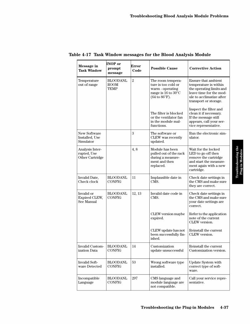
Troubleshooting Blood Analysis Module Problems
Tro
ub
lesh
oo
tin
g t
he
Plu
g-i
n M
od
ule
s
Table 4-17 Task Window messages for the Blood Analysis Module
Message in
Task Window
INOP or
prompt
message
Error
CodePossible Cause Corrective Action
Temperature out of range
BLOODANL ROOM TEMP
2 The room tempera-ture is too cold or warm - operating range is 16 to 30°C (64 to 86°F).
The filter is blocked or the ventilator fan in the module mal-functions.
Ensure that ambient temperature is within the operating limits and leave time for the mod-ule to acclimatize after transport or storage.
Inspect the filter and clean it if necessary.If the message still appears, call your ser-vice representative.
New Software Installed, Use Simulator
3 The software or CLEW was recently updated.
Run the electronic sim-ulator.
Analysis Inter-rupted, Use Other Cartridge
4, 8 Module has been pulled out of the rack during a measure-ment and then replaced.
Wait for the locked LED to go off then remove the cartridge and start the measure-ment again with a new cartridge.
Invalid Date, Check clock
BLOODANL CONFIG
11 Implausible date in CMS.
Check date settings in the CMS and make sure they are correct.
Invalid or Expired CLEW, See Manual
BLOODANL CONFIG
12, 13 Invalid date code in CMS.
CLEW version maybe expired.
CLEW update has not been successfully fin-ished.
Check date settings in the CMS and make sure your date settings are correct.
Refer to the application note of the current CLEW version.
Reinstall the current CLEW version.
Invalid Custom-ization Data
BLOODANL CONFIG
14 Customization update unsuccessful
Reinstall the current Customization version.
Invalid Soft-ware Detected
BLOODANL CONFIG
53 Wrong software type installed.
Update System with correct type of soft-ware.
Incompatible Language
BLOODANL CONFIG
297 CMS language and module language are not compatible.
Call your service repre-sentative.
Troubleshooting the Plug-in Modules 4-37
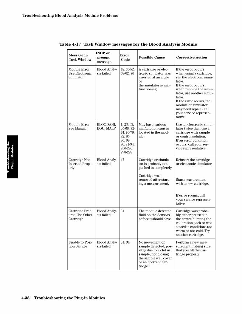
Troubleshooting Blood Analysis Module Problems
Tro
ub
lesh
oo
tin
g t
he
Plu
g-i
n M
od
ule
s
Module Error, Use Electronic Simulator
Blood Analy-sis failed
48, 50-52, 58-62, 70
A cartridge or elec-tronic simulator was inserted at an angle orthe simulator is mal-functioning.
If the error occurs when using a cartridge, run the electronic simu-lator. If the error occurs when running the simu-lator, use another simu-lator.If the error recurs, the module or simulator may need repair - call your service represen-tative.
Module Error, See Manual
BLOODANL EQU. MALF
1, 23, 63, 65-68, 72-74, 76-78, 82, 85, 86, 89, 90, 91-94, 256-296, 298-299
May have various malfunction causes located in the mod-ule.
Use an electronic simu-lator twice then use a cartridge with sample or control solution. If an error condition occurs, call your ser-vice representative.
Cartridge Not Inserted Prop-erly
Blood Analy-sis failed
47 Cartridge or simula-tor is probably not pushed in completely.
Cartridge was removed after start-ing a measurement.
Reinsert the cartridge or electronic simulator.
Start measurement with a new cartridge.
If error recurs, call your service represen-tative.
Cartridge Preb-urst, Use Other Cartridge
Blood Analy-sis failed
21 The module detected fluid on the Sensors before it should have.
Cartridge was proba-bly either pressed in the centre bursting the calibration pack or was stored in conditions too warm or too cold. Try another cartridge.
Unable to Posi-tion Sample
Blood Analy-sis failed
31, 34 No movement of sample detected, pos-sibly due to a clot in sample, not closing the sample well cover or an aberrant car-tridge.
Perform a new mea-surement making sure that you fill the car-tridge properly.
Table 4-17 Task Window messages for the Blood Analysis Module
Message in
Task Window
INOP or
prompt
message
Error
CodePossible Cause Corrective Action
4-38 Troubleshooting the Plug-in Modules

Troubleshooting Blood Analysis Module Problems
Tro
ub
lesh
oo
tin
g t
he
Plu
g-i
n M
od
ule
s
Sample Posi-tioned Short of Fill Mark
Blood Analy-sis failed
35, 36 The cartridge was underfilled, the sam-ple must reach the fill mark.
Perform a new mea-surement making sure that you fill the car-tridge properly.
Sample Posi-tioned Beyond Fill Mark
Blood Analy-sis failed
30, 37 Cartridge was over-filled. The sample was past the fill mark.
Perform a new mea-surement making sure that you fill the car-tridge properly.
Insufficient sample
Blood Analy-sis failed
38, 39 Either not enough sample in the sample well or there are bub-bles in the sample.
Perform a new mea-surement making sure that you fill the car-tridge properly and without bubbles.
Cartridge Error, Use Other Car-tridge
Blood Analy-sis failed
20, 22, 24-29, 32, 33, 40-43, 45, 46, 79, 80, 81, 87
Can be caused by sample related prob-lems, cartridge or module. Single or sporadic errors are most likely a sample-related problem (an interference), an aberrant cartridge or a user-induced situa-tion such as touching contacts or pressing on center of car-tridge.
Try another cartridge.If error recurs repeat-edly, call your service representative.
Cartridge Type Not Recognized
Blood Analy-sis failed
69 Either the cartridge type is not compati-ble with the software revision, or the mod-ule is at fault.
If this is a new type of cartridge being used, arrange a software upgrade.If not, call your service representative.
Table 4-17 Task Window messages for the Blood Analysis Module
Message in
Task Window
INOP or
prompt
message
Error
CodePossible Cause Corrective Action
Troubleshooting the Plug-in Modules 4-39

Troubleshooting EEG Module Problems
Tro
ub
lesh
oo
tin
g t
he
Plu
g-i
n M
od
ule
s
Troubleshooting EEG Module Problems
This section describes how to troubleshoot and correct faults associated with the EEG plug-in module. The procedures for recognizing, isolating, and correcting faults using this module are as follows:
• Identifying a problem based on visual indications or repeated INOPS.
• Using an EEG Module accessory, the EEG Test Device (see Chapter 6 “Parts List for CMS”).
To Troubleshoot the Module
If neither numerics nor a -?- are displayed for the EEG module, perform the following actions:
Step 1 Make sure there is a EEG transducer connected to the module. If not, con-nect one.
Step 2 Make sure the EEG parameter is turned on. Turn it on, if it is not.
Step 3 Make sure the EEG numeric is turned on. Turn it on, if it is not.
Step 4 Make sure you don’t have more than one EEG module plugged into the module racks you are using. If more than one EEG module is plugged in, the supernumerary modules are ignored and should be removed.
Step 5 Check the connection on the module and the rack interface.
1. Unplug and re-plug the EEG module and check if the green LED on the EEG module lights up after re-plugging. If it does not, proceed with the following:
2. Put the EEG module into another slot and check the LED once again. If it lights up now, the connector for the previous slot is faulty and the rack needs to be replaced. If it does not, proceed with the following:
3. Note: this procedure applies only for setups, in which the EEG module
is located in a Satellite Rack. If this does not apply for your situation,
proceed with 4.
Replace the cable from the Satellite Rack to the function box. Again unplug and re-plug the EEG module and check if the LED lights up. If it does not, proceed with the following:
4. Plug any other (not faulty) module into the same slot and check if the LED lights up. If the LED of the alternative module lights up, the EEG module is defect and has to be replaced. If it does not, either the rack or the rack interface card is defect. Proceed with the following:
5. Replace the rack and plug in the EEG module into the new rack. If the LED on the module does not light up, replace the rack interface card in the function box.
4-40 Troubleshooting the Plug-in Modules

Troubleshooting EEG Module Problems
Tro
ub
lesh
oo
tin
g t
he
Plu
g-i
n M
od
ule
s
If a -?- instead of a numeric and one or more INOP messages are displayed for the EEG module, perform the following actions:
Step 1 Check the performance of the module with the EEG test device (if avail-able).The test device enables you to compare the module electrode imped-ance values with the expected values. This information enables you to isolate a problem either to the module or to the cable.
The EEG Test Device looks like a connector cable. One end plugs into the 12-pin connector at the front of the EEG Module. The other end of the Test Device cable is a BNC connector.
The BNC connector of the EEG Test Device can be plugged into a function generator (for example, the Philips 33120A) to generate a simulated EEG sig-nal on the CMS monitor.
Perform the following actions:
1. Select monitoring mode on the CMS.
2. Plug the Test Device into the EEG Module, leaving the BNC connector end unconnected.
3. Press the EEG hardkey on the module.
4. Press the “Electrode Impedance” softkey on the CMS.
5. Check that the observed values in the task window match the following values within ±2 kΩ.
6. If any value is outside the expected value range (±2 kΩ), please replace your EEG Module.
NOTE The Attenuation Factor of the Test Device is 10,000. In testing with a function generator, you must divide the generator amplitude reading by 10,000 or 5,000, depending on the generator used, to match the value on the CMS monitor.
7. If the problem persists, perform step 2 below.
Table 4-18 Expected Impedance Values for EEG Electrodes
Electrode Expected Value
EEG1+ 5 kΩ
EEG1– 10 kΩ
EEG2+ 12 kΩ
EEG2– 15 kΩ
Troubleshooting the Plug-in Modules 4-41

Troubleshooting EEG Module Problems
Tro
ub
lesh
oo
tin
g t
he
Plu
g-i
n M
od
ule
s
.
.
.
.
Step 2 Refer to the following table. Correct the possible cause identified by the INOP message and verify that the INOP disappears. If the problem still exists, replace the module.
Table 4-19 INOP Messages for the EEG Module
INOP Message Possible Cause Corrective Action
EEG UNPLUGGED EEG module is unplugged from the rack.
Perform Step 5 on page 4-40.
EEG EQUIP MALF Malfunction in the EEG mod-ule hardware
Replace module.
EEG NO TRANSDUCER EEG trunk cable disconnected from the module.
Connect EEG trunk cable to moduleIf INOP persists, replace EEG trunk cable.If INOP still persists, replace module
EEG1 LEADS OFF
EEG1 LEAD OFF XXX
Lead electrodes of channel EEG1 are not connected to or have fallen off the patient’s head.If a single lead electrode is dis-connected, the INOP is shown with the electrode location label (e.g. F3).
Connect channel 1 electrodes.
Connect specified electrode (e.g. F3)
EEG2 LEADS OFF
EEG2 LEAD OFF XXX
Lead electrodes of channel EEG2 are not connected to or have fallen off the patient’s head.If a single lead electrode is dis-connected, the INOP is shown with the electrode location label (e.g. F3)
Connect channel 2 electrodes.
Connect specified electrode (e.g. F3)
EEG LEADS OFF If multiple lead electrodes are not connected, this INOP is issued.
Connect electrodes properly (start with reference electrodes).If INOP is still displayed, replace leads.If INOP is still displayed, replace module.
EEG1 LINE NOISEEEG2 LINE NOISE
Excessive Line noise in chan-nel EEG1 or EEG2
Keep all EEG cables together and away from metallic bodies, other cables and radiated fields.
EEG LINE NOISE Excessive Line Noise in both channels at the same time.
Keep all EEG cables together and away from metallic bodies, other cables and radiated fields.
EEG1 OVERRANGEEEG2 OVERRANGE
Input signal is too high. This is usually caused by interfering signals such as line noise or electrosurgery.
Perform corrective action for INOP “EEG LINE NOISE”.If INOP is still displayed, make sure that all electrodes are correctly attached.
4-42 Troubleshooting the Plug-in Modules

Troubleshooting BIS Module Problems
Tro
ub
lesh
oo
tin
g t
he
Plu
g-i
n M
od
ule
s
Troubleshooting BIS Module Problems
This section describes how to troubleshoot and correct faults associated with the BIS components. The procedures for recognizing, isolating, and correcting faults using these components are as follows:
• Identifying a problem based on visual indications or repeated INOPS.
BIS Components Overview
To Troubleshoot the Module
If neither numerics nor a -?- are displayed for the BIS module, perform the following actions:
Step 1 Make sure that BIS Engine, DSC and BIS Sensor are connected to the mod-ule. If not, connect the missing devices.
Step 2 Make sure the BIS parameter is turned on. Turn it on, if it is not.
Step 3 Make sure the BIS numeric is turned on. Turn it on, if it is not.
Step 4 Make sure you don’t have more than one BIS module plugged into the module racks you are using. If more than one BIS module is plugged in, the supernumerary modules are ignored and should be removed.
Step 5 Check the connection on the module and the rack interface.
1. Unplug and re-plug the BIS module and check if the green LED on the BIS module lights up after re-plugging. If it does not, proceed with the following:
2. Put the BIS module into another slot and check the LED once again. If it lights up now, the connector for the previous slot is faulty and the rack needs to be replaced. If it does not, proceed with the following:
3. Note: this procedure applies only for setups, in which the BIS module is located in a Satellite Rack. If this does not apply for your situation,
M1034ASensor DSC BIS EnginePIC
Module Cable
BIS Module
Troubleshooting the Plug-in Modules 4-43

Troubleshooting BIS Module Problems
Tro
ub
lesh
oo
tin
g t
he
Plu
g-i
n M
od
ule
s
proceed with 4.Replace the cable from the Satellite Rack to the function box. Again unplug and re-plug the BIS module and check if the LED lights up. If it does not, proceed with the following:
4. Plug any other (not faulty) module into the same slot and check if the LED lights up. If the LED of the alternative module lights up, the BIS module is defect and has to be replaced. If it does not, either the rack or the rack interface card is defect. Proceed with the following:
5. Replace the rack and plug in the BIS module into the new rack. If the LED on the module does not light up, replace the rack interface card in the function box.
If a -?- instead of a numeric and one or more INOP messages or a small -?- in addition to a numeric are displayed for the BIS module, perform the following actions:
Please note that for proceeding to the next steps a BIS Engine, DSC and BIS Sensor
must be connected to the module.
Step 1 Refer to the following table. Correct the possible cause identified by the INOP message and verify that the INOP disappears.The order of the possible causes reflects their likelihood. Always start with the first to troubleshoot.
Table 4-20 INOP Messages for the BIS Module
INOP Message Possible Cause Corrective Action
BIS UN-PLUGGED BIS module is unplugged from the rack.
Perform Step 5 on page 4-43
BIS MODULE MALFUNC Malfunction in the BIS module hardware.
Overcurrent situation.
Enter BIS Task Window1.Look for the message “BIS Engine or DSC overcurrent”. If it is not dis-played, replace BIS module.
If it is displayed, perform the follow-ing procedure:Disconnect the BIS Engine from mod-ule and replug BIS module. If INOP persists, replace module.If INOP disappears, reconnect BIS Engine without DSC to module. If INOP persists, replace BIS Engine.If INOP disappears, reconnect DSC to BIS Engine. If INOP persists, replace DSC.If INOP disappears, replace Module Cable.
BIS ENGINE DISCONN BIS Engine not con-nected.
Module Cable defec-tive.
Make sure that the Module Cable is properly connected.
If INOP persists replace Module Cable.
4-44 Troubleshooting the Plug-in Modules

Troubleshooting BIS Module Problems
Tro
ub
lesh
oo
tin
g t
he
Plu
g-i
n M
od
ule
s
BIS ENGINE INCOMPAT BIS Engine Software is not supported.
A software upgrade may be required.Enter BIS Task Window1 and write down the Revision numbers dis-played for “Module FW Rev” and “BIS Eng SW Rev”. Check the latest ver-sion of the compatibility matrix pro-vided either on page 4-51 or in the latest Service Note, whichever is more recent.
BIS ENGINE MALFUNC Malfunction in the BIS Engine hardware.
Replace BIS Engine.
BIS DSC DISCONN DSC is not properly connected
Either DSC cable or BIS Engine may be faulty.
Make sure that the DSC is properly connected to the adjacent devices.
If INOP persists replace DSC2.If INOP persists replace BIS Engine.
BIS DSC MALFUNC Electrocautery used during self-test.
Malfunction in the BIS DSC hardware.
PIC may be faulty.
Make sure not to use electrocautery during the self-test procedure.
Perform a PIC/DSC Test as described under “General Test Pro-cedures for the BIS components” on page 4-48. If it fails replace DSC2.
If INOP persists replace PIC.
BIS DSC INCOMPAT DSC is not supported by the BIS Engine or new DSC connected to an old BIS Engine.
A software upgrade may be required.Enter BIS Task Window1 and note the Revision number displayed for “BIS Eng SW Rev” and the DSC ID. Check the latest version of the compatibility matrix provided either on page 4-51 or in the latest Service Note, which-ever is more recent.
BIS SENSOR MALFUNC Malfunction in the Sen-sor hardware, most often caused by liquids permeating into the connectors.
PIC or short cable of the DSC may be faulty.
Replace Sensor.Enter BIS Task Window1 and press “START CHECK” to initiate a Cyclic Impedance Check. Make sure all leads have passed the test.Make sure that the PIC connector (between PIC and Sensor) is dry. If you are not sure that the connector is dry, replace PIC until it has dried.
If INOP persists perform the PIC/DSC Test as described under “Gen-eral Test Procedures for the BIS components” on page 4-48. If it fails replace PIC.If INOP persists replace DSC2.
Table 4-20 INOP Messages for the BIS Module
INOP Message Possible Cause Corrective Action
Troubleshooting the Plug-in Modules 4-45

Troubleshooting BIS Module Problems
Tro
ub
lesh
oo
tin
g t
he
Plu
g-i
n M
od
ule
s
BIS SENSOR DISCONN Sensor not properly connected to PIC and/or PIC not properly connected to DSC.
Sensor or PIC or short cable of DSC faulty.
Make sure that the BIS Sensor is properly connected to the PIC and the PIC is properly connected to the DSC.
If INOP persists, perform a PIC/DSC Test as described under “General Test Procedures for the BIS compo-nents” on page 4-48. If it fails replace Sensor. If INOP persists replace PIC.If INOP persists replace DSC2.
BIS SENSOR INCOMP Unsupported Sensor connected or Sensor type unknown.
PIC or short cable of the DSC may be faulty.
Make sure to use only Philips sup-ported Sensors.
Perform the PIC/DSC Test as described under “General Test Pro-cedures for the BIS components” on page 4-48. If it fails replace PIC.If INOP persists replace DSC2.
BIS SENSOR USAGE Sensor expired due to too often usage.
PIC or short cable of the DSC may be faulty.
Replace Sensor.Enter BIS Task Window. Make sure all leads have passed the Cyclic Impedance Check, which has been automatically performed.
Perform the PIC/DSC Test as described under “General Test Pro-cedures for the BIS components” on page 4-48. If it fails replace PIC.If INOP persists replace DSC2.
BIS SQI < 15% The signal quality is below 15% and the BIS value cannot be cacu-lated. This may occur as a result of artifact such as those generated from motion or the presence of electrocau-tery devices.
Make sure the Sensor is properly attached to the patient: Enter BIS Task Window1 and press “START CHECK” to initiate a Cyclic Imped-ance Check. Make sure all leads have passed the test.
Make sure the patient is completely relaxed (even small motions of the facial muscles affect the signal qual-ity).
BIS IMPEDANCE CHCK The Cyclic Impedance check is running.
Wait until Cyclic Impedance Check has finished or press “STOP CHECK” in the Cyclic Check Task Window.
BIS LEAD OFF One or more leads (electrodes) have no skin contact.
Press the electrode pads firmly.If INOP persists, replace Sensor pro-viding proper skin preparation.
Table 4-20 INOP Messages for the BIS Module
INOP Message Possible Cause Corrective Action
4-46 Troubleshooting the Plug-in Modules

Troubleshooting BIS Module Problems
Tro
ub
lesh
oo
tin
g t
he
Plu
g-i
n M
od
ule
s
BIS HIGH IMPEDANCE Impedance of one or more electrode(s) is above the valid range, most often caused by bad skin preparation.
PIC or short cable of the DSC faulty.
Press the electrode pads firmly.If INOP persists, replace Sensor pro-viding proper skin preparation.
If INOP persists perform a PIC/DSC Test as described under “General Test Procedures for the BIS compo-nents” on page 4-48. If it fails replace PIC.If INOP persists replace DSC2.
BIS ISOELECTRC EEG No discernible EEG activity is detected for longer than 1 minute.
Check the patient. Check the leads for proper connection.
BIS SQI < 50% The signal quality is below 50%. This may occur as a result of arti-fact such as those gen-erated from motion or the presence of electro-cautery devices.
Make sure the Sensor is properly attached to the patient: Enter BIS Task Window1 and press “START CHECK” to initiate a Cyclic Imped-ance Check. Make sure all leads have passed the test.
Make sure the patient is completely relaxed (even small motions of the facial muscles affect the signal qual-ity).
1. To enter BIS Task Window press (in Monitoring Mode) MODULE SETUP fol-lowed by BIS
2. Before ordering a new DSC, try another one of the same type, if available.
Table 4-20 INOP Messages for the BIS Module
INOP Message Possible Cause Corrective Action
Troubleshooting the Plug-in Modules 4-47

Troubleshooting BIS Module Problems
Tro
ub
lesh
oo
tin
g t
he
Plu
g-i
n M
od
ule
s
General Test Procedures for the BIS components
PIC/DSC Test
TEST In Monitoring mode connect the Sensor Simulator (for maximum usage please refer to the documentation delivered with the Sensor Simulator) to the Patient Interface Cable (for part numbers please refer to Table 6-17 on page 6-26).
Enter the BIS Task Window by pressing , followed by .
Start Impedance Check by pressing . This brings up the BIS Cyclic Check Task Window. Check the displayed results.
RESULTS PIC and DSC are functioning correctly and the test is passed, if the following results are displayed:
If the test fails, firstly replace PIC with a known good one. Perform test again. If it fails again, DSC is faulty and has to be replaced.
NOTE If the DSC/PIC Test alternately passes and fails, this indicates a broken DSC cable. In this case you also have to replace the DSC.
DSC Self-Test
If the correct functioning of the DSC is in doubt, perform the DSC self-test.
NOTE The DSC and long cable only are covered by this test, not the short cable (which can be tested by the PIC/DSC Test described above).This test is not available directly after connecting the DSC. Wait at least 10 seconds until the DSC has stabilized.Do not run this test while electrocautery equipment is in use. This will cause a failure.
TEST Enter Service Mode
Enter the BIS Task Window by pressing , followed by .
Start Test by pressing .
RESULTS DSC is functioning correctly and the test is passed with the following results displayed:
Electrode Expected Value
1 4-6 kΩ
2 8-12 kΩ
3 1-3 kΩ
Module SetupBIS
Start Check
Module SetupBIS
Test DSC
4-48 Troubleshooting the Plug-in Modules

Troubleshooting BIS Module Problems
Tro
ub
lesh
oo
tin
g t
he
Plu
g-i
n M
od
ule
s
Module: Test passedBIS Engine: Test passedDSC: Test passed
The small table located right of the “DSC Test passed / failed” entry lists more detailed results of the DSC Self-Test.
Additional information available in the Service Mode Task Window
The Service Mode Task Window provides additional information, which is explained in the following section. To enter the window, change to Service Mode and press
followed by . Please wait at least 10 seconds until all results are valid. If the connected sensor has a malfunction (indicated by “Test failed” in the Sensor section of the Service Mode Task Window), in some cases it is necessary that you disconnect the sensor and un- and replug the module before continuing.
Note: the screen shown above is only an example and does not show real data.
For an explanation of the individual entries see next page.
Module Setup BIS
Troubleshooting the Plug-in Modules 4-49

Troubleshooting BIS Module Problems
Tro
ub
lesh
oo
tin
g t
he
Plu
g-i
n M
od
ule
s
Module DSC
FW Rev Installed Firmware Revision of the BIS module.
ID Type of DSC used.Supported types:9 (DSC-3) & 10 (DSC-XP)
S/N1
1. If no number is shown behind S/N, please refer to the rear side of the BIS module.
Serial Number of the BIS module used. FW Rev Installed Firmware Revision of the DSC.
Test passed / failed
Result of the automatic BIS Self-Test2.
2. Initiated by entering the Service Mode, switching Power On/Off or un-, replugging the BIS module.
Test passed / failed Result of the automatic BIS Self-Testb as well as the manually started DSC Self-Test, described on page 4-46
BIS Engine
GainHigh Pass blockedHigh Pass normalNoise
Detailed results of the DSC Self-Test.
S/N Serial Number of the BIS Engine used. PIC
SW Rev Installed Software Revision of the BIS Engine.
ID With Sensor connected, the ID identifies the class of Sensors used.Supported classes: 7
Prot Rev Protocol Revision of the BIS Engine used. Required for compatibility check between BIS Engine and BIS module.
Sensor
FW Rev Installed Firmware Revision of the BIS Engine.
S/N Serial Number of the BIS Sensor used.
HW Rev Hardware Revision of the BIS Engine used.
Code Production related information.
Test passed / failed
Result of the automatic BIS Self-Testb. Type Type of Sensor used.Supported types: 1 (Adult Patient Sensor Plus)2 (Adult Patient Sensor XP)3 (Pediatric Patient Sensor)8 (Sensor Simulator - 1 channel)9 (Sensor Simulator - 2 channel)
Diag data Information for internal use only. Test passed / failed Result of the automatic BIS Self-Testb.
4-50 Troubleshooting the Plug-in Modules

Troubleshooting BIS Module Problems
Tro
ub
lesh
oo
tin
g t
he
Plu
g-i
n M
od
ule
s
Compatibility Matrix
The following table indicates the revisions of the BIS Module and BIS Engine that are allowed to be used with the various DSC, PIC and Sensor types. Only the fields marked with a $ indicate a valid combination. Due to the low update frequency of this manual it is likely that a more recent version of this matrix has already been issued via a Service Note. Always refer to the latest version.
Module FW Rev BIS Engine SW Rev
A.01.xx 1.xx 2.xx
DSC-3 ID 9 $ $ $
DSC-XP ID 10 $ -- $
PIC ID 7 $ $ $
Sensor type:
Plus 1 $ $ $
XP 2 $ $ $
Pediatric 3 $ $ $
Simulator (1 Channel) 8 $ $ $
Simulator (2 Channel) 9 $ $ $
Troubleshooting the Plug-in Modules 4-51

Troubleshooting VueLink Module Problems
Tro
ub
lesh
oo
tin
g t
he
Plu
g-i
n M
od
ule
s
Troubleshooting VueLink Module Problems
NOTE For detailed troubleshooting information on the VueLink module, please refer to the documentation delivered with your external device driver.
For general testing of the VueLink module the following test procedure can be performed:
M1032A VueLink Tests using VueLink Test Module
The VueLink Test Module (part number M1186-60510) is a plug-in module used to test M1032A VueLink modules in the Philips CMS Patient Monitoring System.
Test Procedure
The following steps are the procedure for testing a VueLink module using the VueLink Test Module. In order to run the test, the Test Module must be preselected ON in Config Mode. This means that the Test Module must be one of the devices made available for selection during configuration of the VueLink Module.
The test itself is carried out in Monitoring Mode. For information concerning the configuration of VueLink modules see the M1032A VueLink Module Handbook (part number M1032-9000B).
Step 1 Plug the VueLink module into the module rack on the CMS.
Step 2 Press the Setup key on the front of the VueLink module.
Step 3 Press .
Step 4 In the window that appears, select “Test Module” using the soft-key. It is important to note which device driver was previously selected, in order to be able to reset it at the end of the test. (It will be labeled on the front of the VueLink Module.)
Step 5 Press to store the selection and wait for the message “Switched to new device”.
Step 6 Plug in the Test Module.
Step 7 Connect the modules by plugging one end of the cable (part number M1032-61661) into the connector on the front of the VueLink Module, and the other end into the connector on the front of the Test Module.
Step 8 Press to make the Test Module Task Window appear on the screen.Note: The key is hollow and therefore cannot be selected.
Select Device
Next Device
Confirm
Setup VueLink
Scale Wave
4-52 Troubleshooting the Plug-in Modules

Troubleshooting VueLink Module Problems
Tro
ub
lesh
oo
tin
g t
he
Plu
g-i
n M
od
ule
s
The test module acts in the same way as an external device would, and sends signals to the VueLink module in both analog and digital form. The computer module checks these signals for validity, and then displays “passed” or “failed” on the screen.
The Task Window displays two waveforms, a triangular one and a rectangular one. These are displayed alternately and for a period of ten seconds each. The expected curve type is indicated below the wave.
There are two pairs of gridlines that indicate the permitted range for the max/min values of these waves. If all the data received by the test module is correct, the waves will lie within the specified ranges. If either limit of either wave falls outside the respective gridlines, then the module being tested is faulty regardless of the passed/failed messages.
The and softkeys are of no use in this test since would inhibit the update of the “Passed/Failed” messages.
When the test is complete:
Step 1 Disconnect the cable that joins the Test Module to the VueLink module.
Step 2 In Config Mode, ensure that the Test Module is set OFF, and the preselected devices are the same ones as before the test. Also, verify the settings for these devices.
Step 3 Return to Monitoring Mode.
Step 4 Press the Setup key on the front of the VueLink module and select the required device using the softkey.
NOTE It is important to ensure that the preselected device drivers are configured exactly the same as they were before the test (including default settings).
Freeze Values Update ValuesFreeze Values
Next Device
Troubleshooting the Plug-in Modules 4-53

Performing Plug-In Module Self-Tests
Tro
ub
lesh
oo
tin
g t
he
Plu
g-i
n M
od
ule
s
Performing Plug-In Module Self-Tests
The CMS contains auto-tests and self-tests that are designed to demonstrate that the monitor is interacting with the plug-in modules.
Objective
In order to meet the chapter’s goals, you should be able to perform a plug-in module self-test and identify the normal outputs of a self-test.
Concepts
This Philips patient monitor has a module self-test which generates and displays test waveforms and corresponding numerics for all the modules that are connected through a rack and turned on. The test signals are displayed for about 30 seconds and then the display returns to the normal monitoring mode.
The test signal will be displayed only if the system power-on sequence was successful and the module is plugged into a rack in the system and turned ON. Perform the following quick system check to verify that computer module, integral rack and plug-in modules are communicating properly before verifying the individual parameter modules.
Performing a Quick System Check
You can verify that the System board, integral rack and modules are communicating properly by completing the following test.
TEST Press the ECG key on the front of the ECG module in a system that is turned ON.
RESULT Pressing the ECG key brings up the ECG Task Window and verifies that the System board and integral rack are communicating with the plug-in module.
If the plug-in module Task Window, waveform or numeric is missing from the display, the module may not be turned ON. Try pushing the key on the plug-in module to see if the system is communicating with the module. If the ECG module does not respond, perform the module self-test.
To turn a parameter ON, press the following key sequence:
or (if using Classic Control Panel)
The self-test ensures
that the system is
functioning
correctly; it does
not troubleshoot the
system.
Module Setup Parameters
Parametr On/OffPtsReference
Select ParametrPtsReference
On/Off Setup PtsReference
4-54 Troubleshooting the Plug-in Modules

Performing Plug-In Module Self-Tests
Tro
ub
lesh
oo
tin
g t
he
Plu
g-i
n M
od
ule
s
Self-Test Procedure Overview
Step 1 Choose a patient category (Adult/Pedi/Neo) by pressing the following key sequence:
or (if using Classic Control Panel
Step 2 Display 30 seconds of the waveforms and numerics of all connected modules by pressing:
(or )
Step 3 Repeat Step 2 as necessary to check the individual test waveforms and numerics for the category.
Step 4 Use Step 1 to choose a new patient category and repeat Steps 2 and 3.
See the following table for test values.
Table 4-21 System Self-Test Values
Module Test Numeric Test Waveform
ECG 100 bpm in ADULT mode 125bpm in NEO/PED mode
Simulated Square Wave
RESP 15 rpm in ADULT mode 30 rpm in PEDI mode 55 rpm in NEO mode
Simulated Wave
Pressure Systolic 120 mmHg ADULT 60 mmHg PEDI/NEO
Simulated squarewave
Pressure Diastolic 0 mmHg ADULT 0 mmHg PEDI/NEO
Simulated squarewave
SpO2 100% No Wave
Pleth Wave on display Simulated wave
Cardiac OutputBlood TempInj Temp
5 l/min (+0.1 l/min) 37°C0°C
No wave
tcpO2 60 mmHg (8.0 kPa) No wave
tcpCO2 40 mmHg (5.3 kPa) No wave
Module Setup Instrument Config
Config SetsPtsReference
Change Pat CategPtsReference
Monitor Setup Instrument Config
Test SignalsPtsReferenceSignals
Troubleshooting the Plug-in Modules 4-55

Performing Plug-In Module Self-Tests
Tro
ub
lesh
oo
tin
g t
he
Plu
g-i
n M
od
ule
s
Example of an extended Self-Test display showing all possible waveforms
NOTE The following self-tests give the key sequence for the Standard Control Panel. If you are using a Classic Control Panel then you will use the hardkey instead of the hardkey.
ETCO2 40 mmHg (6.0 kPa) Simulated squarewave
IMCO2 0 mmHg (0.0 kPa) Simulated squarewave
AWRR 25 rpm
Temperature 40°C (104°F) No wave
Table 4-21 System Self-Test Values
Module Test Numeric Test Waveform
BED 17 Adult 23 FEB 89 18:19
HR Test Signals active - No monitoring!II HR
100
120
0
ABPABP
120/O (60)
PAP120
0
PAP
40
0
CO2
120/0 (58)
NBP
0/0
ETCO2
5.00
18:19PLETH
RESP
100
15
1mV
RESP
Tblood
10nm
M HR
SpO2 SQI
SpO2
IMCO2
C.O.
Non-paced mode
(0)
400
37.0
AWRR 25
Instrument Config
Monitor Setup
4-56 Troubleshooting the Plug-in Modules

Performing Plug-In Module Self-Tests
Tro
ub
lesh
oo
tin
g t
he
Plu
g-i
n M
od
ule
s
Performing the ECG or ECG/RESP Module Self-Test
Auto Check: None.
Self-Test: The ECG and ECG/RESP self-test may be performed at any time as the lead selector and pace pulse detection are inhibited during the check. The module will produce ECG test signals at the beginning of the processing circuitry, and process the test signals in the same way patient signals are processed. The test signals last about 30 seconds and then the display returns to the normal monitoring mode.
TEST Press
RESULT If the module is functioning correctly, the following heart rate and respiration are displayed without the alarms being activated:
ECG 100 bpm in ADULT mode125 bpm in NEO/PEDI mode
RESP 15 rpm in ADULT mode30 rpm in PEDI mode55 rpm in NEO mode
Performing the M1006A/B Pressure Module Self-Test
Auto Check: The check for these modules is started every time the system is switched ON and checks the complete module circuitry, including the sensitivity detection circuit.
Self-Test: The test signals last about 30 seconds and then the display returns to the normal monitoring mode.
The M1006A Pressure self-test may be performed at any time as the input switch switches the CAL divider to 0 mmHg, and the pressure test signals bypass the sensitivity detection circuit. From here, the signals are processed in the same way as the patient signals.
The M1006B Pressure self-test may be performed at any time, as the signal is output from a microcontroller. From here, the test signal is processed in the same way as a patient signal, testing the complete signal path from the module to the display.
TEST Press
RESULT If the module is functioning correctly, the following systolic and diastolic pressures are displayed without the alarms being activated:
Systolic 120 mmHg ADULT60 mmHg PEDI/NEO
Diastolic 0 mmHg ADULT 0 mmHg PEDI/NEO
ECG test signals
are rectangular
pulses, which
represent beat-to-
beat heart rate, and
are not the same as
the ECG signals
expected from a
patient.
Monitor Setup Test Signals
The pressure
waveform provided
is not the same as
the waveform which
would be expected
from a patient.
Monitor Setup Test Signals
Troubleshooting the Plug-in Modules 4-57

Performing Plug-In Module Self-Tests
Tro
ub
lesh
oo
tin
g t
he
Plu
g-i
n M
od
ule
s
CAUTION For the M1006A/B Pressure modules with analog output (Option #CO1), do not
attempt defibrillation unless pump cable is connected at both ends or
disconnected entirely. The signal to the balloon pump stops when a self-test is in
progress or in Demo, Configuration or Service Modes.
Performing the NBP Module Self-Test
Auto Check: The NBP module performs a check periodically during operation.
Self-Test: None.
Performing the SpO2/Pleth Module Self-Test
Auto Check: None.
Self-Test: The SpO2/Pleth module self-test may be performed at any time. The integral waveform generator in the module produces test signals using the current driver at the beginning of the processing circuitry. The test signals are processed in the same way as patient signals are processed. The test signals last about 30 seconds and then the display returns to the normal monitoring mode.
TEST Press .
RESULT If the module is functioning correctly, the following derived values and waveform are displayed without the alarms being activated:
SpO2 100%
Pleth Wave height after auto gain is 100% of scale height
Pulse Rate 100 bpm in ADULT mode125 bpm in NEO/PEDI mode
This module has no
test waves or
numerics.
The SpO2/Pleth test
waveform is a Pleth
rectangular wave
which represents
the signal from the
photo-diode in the
SpO2 transducer
assembly.
Monitor Setup Test Signals
4-58 Troubleshooting the Plug-in Modules

Performing Plug-In Module Self-Tests
Tro
ub
lesh
oo
tin
g t
he
Plu
g-i
n M
od
ule
s
Performing the Cardiac Output Module Self-Test
Auto Check: None.
Self-Test: The Cardiac Output module test may be performed at any time. The test signal lasts about 30 seconds and then the display returns to the normal monitoring mode.
TEST Press
RESULT If the module is functioning correctly, the following derived values will be displayed without the alarms being activated:
C.O. 5.0 liters/min (+0.1 liters/min)
TBlood 37C + 0.1C
Tinj 0C + 0.1C
Performing the tcpO2/tcpCO2 Module Self-Test
Auto Check: The check is performed automatically when the system is switched on, during calibration, and continuously when no transducer is connected. When the auto check fails, the INOP message: Equipment Malfunction is given (refer to the Troubleshooting Chapter in this manual for troubleshooting details).
Self-Test: The tcpO2/tcpCO2 module self-test may be performed at any time. The test signal lasts about 30 seconds and then the display returns to the normal monitoring mode.
TEST Press
RESULT If the module is functioning correctly, the following numerics are displayed without the alarms being activated:
tcpO2 60 mmHg (8.0 kPa)
tcpCO2 40 mmHg (5.3 kPa)
CAUTION Radiated immunity: If operating under conditions according to EN 60601-1-2 up
to 1 V/m electrical field strength, the following deviations in the measurements
could occur: tcpO2 2 mmHg or less, tcpCO2 1 mmHg or less. It is recommended to
avoid the use of electrically radiating devices in close proximity to a tcpO2/
tcpCO2 monitor.
This module only
displays numerics.
Monitor Setup Test Signals
This module only
displays numerics.
Monitor Setup Test Signals
Troubleshooting the Plug-in Modules 4-59
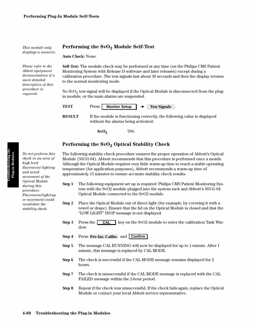
Performing Plug-In Module Self-Tests
Tro
ub
lesh
oo
tin
g t
he
Plu
g-i
n M
od
ule
s
Performing the SvO2 Module Self-Test
Auto Check: None.
Self-Test: The module check may be performed at any time (on the Philips CMS Patient Monitoring System with Release D software and later releases) except during a calibration procedure. The test signals last about 30 seconds and then the display returns to the normal monitoring mode.
No SvO2 test signal will be displayed if the Optical Module is disconnected from the plug-in module, or the main alarms are suspended.
TEST Press .
RESULT If the module is functioning correctly, the following value is displayed without the alarms being activated:
SvO2 70%
Performing the SvO2 Optical Stability Check
The following stability check procedure ensures the proper operation of Abbott’s Optical Module (50131-04). Abbott recommends that this procedure is performed once a month. Although the Optical Module requires very little warm-up time to reach a stable operating temperature (for application purposes), Abbott recommends a warm-up time of approximately 15 minutes to ensure accurate stability check results.
Step 1 The following equipment set up is required: Philips CMS Patient Monitoring Sys-tem with the SvO2 module plugged into the system rack and Abbott's 50131-04 Optical Module connected to the SvO2 module.
Step 2 Place the Optical Module out of direct light (for example, by covering it with a towel or drape). Ensure that the lid on the Optical Module is closed and that the “LOW LIGHT” INOP message is not displayed.
Step 3 Press the key on the SvO2 module to enter the calibration Task Win-dow.
Step 4 Press and .
Step 5 The message CAL RUNNING will now be displayed for up to 1 minute. After 1 minute, this message is replaced by CAL MODE.
Step 6 The check is successful if the CAL MODE message remains displayed for 2 hours.
Step 7 The check is unsuccessful if the CAL MODE message is replaced with the CAL FAILED message within the 2-hour period.
Step 8 Repeat if the check was unsuccessful. If the check fails again, replace the Optical Module or contact your local Abbott service representative.
This module only
displays a numeric.
Please refer to the
Abbott equipment
documentation if a
more detailed
description of this
procedure is
required.
Monitor Setup Test Signals
Do not perform this
check in an area of
high level
fluorescent lighting
and avoid
movement of the
Optical Module
during this
procedure.
Fluorescent lighting
or movement could
invalidate the
stability check.
CAL
Pre-Ins. Calibr. Confirm
4-60 Troubleshooting the Plug-in Modules

Performing Plug-In Module Self-Tests
Tro
ub
lesh
oo
tin
g t
he
Plu
g-i
n M
od
ule
s
Performing the FIO2 Module Self-Test
Auto Check: A continuous check of the OFFSET and TEST values is executed to ensure that they are within the specified limits. If one of these values is found to be outside its limit, a FIO2 EQUIP MALF message is displayed.
If the BATTERY values go outside the specified range, a FIO2 BATTERY? message is displayed. FIO2 monitoring continues, but the backup feature of the module cannot be guaranteed, leading to a possible drift of the FIO2 numeric.
Self-Test The manual check may be performed at any time. The check takes approximately 30 seconds, after which time the display automatically returns to the normal monitoring mode.
TEST Press .
RESULT If the module is functioning correctly the following numeric will be displayed without the alarms being activated:
FIO2 0.21 (if no errors from the Auto-Test)
Performing the CO2 Module Self-Test
Auto Check: None.
Self-Test: The self-test may be performed at any time. The test signals last about 30 seconds, and then the display returns to the normal monitoring mode.
TEST If a transducer is connected to the module, the following conditions must be met:
• The motor in the transducer is running.• No heater malfunction is reported.
Press .
RESULT If the module is functioning correctly the values will be displayed without the alarms being activated and should read as follows:
ET CO2 40 mmHg (6.0kPa)
IMCO2 0 mmHg (0.0kPa)
AWRR 25 rpm
Monitor Setup More Choices Test Signals
The simulated CO2
wave is provided on
the display with the
numerics.
Monitor Setup Test Signals
Troubleshooting the Plug-in Modules 4-61

Performing Plug-In Module Self-Tests
Tro
ub
lesh
oo
tin
g t
he
Plu
g-i
n M
od
ule
s
Performing the Temperature Module Self-Test
Auto Check: None.
Self-Test: The Temperature module self-test may be performed at any time as the switch network switches to the reference resistors for the duration of the check. The system connects the reference resistors to the beginning of the processing circuitry, and processes this test value in the same way as the patient values are processed. The test signals last about 30 seconds and then the display returns to the normal monitoring mode.
TEST Press .
RESULT If the module is functioning correctly, the following temperature will be displayed without the alarms being activated:
Temp 40 C (+0.1C)
Performing the Blood Analysis Module Self-Test
Auto Check: The Blood Analysis module performs a check when the system is switched on.
Self-Test: The Self-Test with the External Simulator M3634A may be performed at any time.
TEST Insert the External Simulator into the cartridge slot of the module.
RESULT Either PASS or FAIL will be displayed on the Monitor to indicate whether the module has passed the self-test or not. If the module fails the self-test, try the procedure again. If it fails again, wait half an hour and then try the procedure again. If the module continues to fail the self-test the module should be replaced.
This module only
displays a numeric.
Monitor Setup Test Signals
4-62 Troubleshooting the Plug-in Modules

Performing Plug-In Module Self-Tests
Tro
ub
lesh
oo
tin
g t
he
Plu
g-i
n M
od
ule
s
Performing the Recorder Module Self-Test
Auto Check: The Recorder module performs a check when it is plugged in to the front-end rack of the system.
Self-Test: The Recorder module check may be performed at any time.
TEST Turn on the system power and plug in the recorder module.
RESULT The LED on the front panel indicates whether the module has passed the self-test by flashing.
Two flashes Module has passed check.
One flash Module failed self-test. Take the module out and try the procedure again to make sure there is a good connection.
No flash Module processors are not working properly and the module should be replaced.
Performing the VueLink Module Self-Test
Auto Check: The VueLink module performs an automatic check when the module is plugged in to the module rack of the system.
Self-Test: None.
Performing the Data Management Database Self-Test
The data management database is tested during system start-up with an SRAM checksum procedure. If there is an error found in the SRAM checksum, the system will restart (cold start) and all patient data will be lost.
The recorder
module produces a
sequence of LED
flashes when tested.
Refer to M1032A
VueLink Module
Handbook for
further service
details on the
VueLink Modules.
Troubleshooting the Plug-in Modules 4-63

Performing Plug-In Module Self-Tests
Tro
ub
lesh
oo
tin
g t
he
Plu
g-i
n M
od
ule
s
Performing the RS-232 Card Loopback Test
An RS-232 Transmit/Receive (loopback) test can be performed to check both the transmit and the receive capabilities of the RS-232 ports. The test is performed as follows:
Step 1 Change to Service Mode.
Step 2 Connect the RS-232 cable (M1181A #A50 or #A51) directly from one of the RS-232 ports to the other on the same card.
Step 3 Ensure that all other connections to host computers are removed.
Step 4 Press (or ).
Step 5 Press .
Step 6 Using the softkeys, configure both ports to:
• “Comp On”• the same baud rate (for example: 19200)• the same Tx/Rx byte order (for example: High/Low).
Step 7 Press and then press .
Step 8 Press to initiate the loopback test.
NOTE The message “RS232 port receive and transmit test passed” appears with “Port #1 <-> Port #2” if the test is successful; if not, the message “RS232 port transmit and receive test failed” appears. If the test is unsuccessful, both the cable and the RS-232 card should be examined and/or exchanged.
NOTE If you have two RS-232 boards in the monitor, you can also cross connect between the RS-232 boards. The message that appears could be “Port #1 <-> Port #4” if ports 1 and 4 are connected for the test.
Monitor Setup Instrument Config
RS232
Store Settings Confirm
Perform Test
4-64 Troubleshooting the Plug-in Modules

Chapter 5 Repairing the CMS
Rep
air
ing t
he C
MS
This chapter explains how to remove and replace the assemblies that make up the CMS. Generally, you will be referred to this chapter to remove an assembly that is suspected to be faulty, or to replace an assembly as part of a hardware revision. In any event, this chapter describes how to disassemble the CMS to the point required to replace a selected assembly, gives any special tools required to do the job, and gives any cautions or warnings associated with the removal and replacement procedures.
Objective
In order to meet the chapter’s goals, you should be able to locate and understand the removal and replacement procedures for the CMS.
Concepts
The CMS contains the following major units:
• Main Display Module – Main displays are 14” Mono, 14” Color or 10.4” Flatscreen color and provide a control panel for the human interface. Alternatively, you can have a 15” XGA-compatible display1 as your main display (M1167A/77A Option H03) in which case the control panel is the separate Handheld Keypad with External Alarm Device.
• Slave/Independent Display Modules – Slave/Independent displays are 10.4” Flatscreen color, off-the-shelf XGA display1, 14” Mono, 14” Color or 21” Color, and contain no control panel.
• Handheld Keypad (optional, except for M1167A/77A Option H03) – The handheld keypad is an input device used with the main display to interact with patient data management and drug calculator software.
• Computer Module – The computer module contains the hardware and software for the processing functions of the monitor. Most of the external connections of the monitor are in the rear of the computer module.
• Plug-in Module Rack (Integral or Satellite) – The plug-in module rack is the interface between the plug-in modules and the computer module. Module racks can be integrated in the computer module or remotely located in the patient vicinity.
• Plug-in Modules – The plug-in modules are the interface between the patient cables and the plug-in module rack. Each module is responsible for specific measurements. The number and type of modules used will depend on the monitoring situation.
1. Disassembly and repair of any off-the-shelf XGA display are outside the scope of this book. Refer to the manual that comes with the display. For details of the appropriate Safety Tests, see Chapter 2.
Repairing the CMS 5-1

Procedure Overview
Rep
air
ing t
he C
MS
Procedure Overview
This chapter contains the following procedures:
Each section that covers an assembly contains its own procedure overview.
Display Module Overview
Differences Between Models
The CMS is available under model numbers 54 through 68, the ACMS is available under model numbers 74 through 88 and the NCMS is available under model numbers 36 through 48.
The CMS / ACMS / NCMS models 3x, 5x and 7x use the M1092A Monochrome display. Model numbers 4x, 6x and 8x use the M1094B 14” Color display (or M1094A in older models), M1095A Flatscreen, or XGA-compatible display.
The procedures in this chapter are split into sections. The first section deals with the M1092A and M1094A displays modules, identifying differences as necessary. The second section deals with the M1094B display module. The third section deals with the M1095A Flatscreen display module.
Table 5-1 Procedure Overview for Removing and Replacing Parts
Assembly Page
Display Module Overview 5-2
M1092A and M1094A Removal and Replacement Procedures 5-3
M1094B Removal and Replacement Procedures 5-22
M1095A Backlight Removal and Replacement Procedures 5-32
Handheld Keypad 5-39
External Alarm Device 5-40
Computer Module Removal and Replacement 5-44
Module Rack 5-61
Plug-in Modules 5-63
5-2 Repairing the CMS

M1092A and M1094A Removal and Replacement Procedures
Rep
air
ing t
he C
MS
M1092A and M1094A Removal and Replacement Procedures
This section’s procedures are listed in the following table. The procedures apply to both the M1092A (monochrome) and M1094A (color) monitors. Any differences are noted.
Table 5-2 Replaceable Parts for the CRT Display Module
Replaceable PartM1092A
go to Page
M1094A
go to Page
M1094B
go to Page
Rear Cover 5-4 5-4 5-22
Power Fail Relay (French ICU Option) 5-5 5-5 -
Power Fuses 5-6 5-6 5-23
Line Power Filter (M1094A Display) - 5-8 -
Rear Enclosure 5-9 5-9 5-24
Locking Cam 5-10 5-10 5-25
Front Assembly 5-11 5-11 5-26
Human Interface Board 5-12 5-12 5-27
Membrane Switch 5-13 5-13 5-29
Metal Cover 5-14 5-14 5-30
Fuse Assembly 5-16 5-16 -
Switch-Mode Power Supply (M1092A) 5-18 - -
Switch-Mode Power Supply (M1094A) - 5-20 -
Switch-Mode Power Supply - - 5-31
Video/Philips-HIL Connector PCA 5-22 5-22 -
Repairing the CMS 5-3

M1092A and M1094A Removal and Replacement Procedures
Rep
air
ing t
he C
MS
Rear Cover
To Remove the Rear Cover
No other assemblies need to be removed to remove the rear cover.
Step 1 Slide the two spring locks toward the center of the cover and lift the lower edge of the cover.
Step 2 Raise the cover so it is horizontal and slide the cover directly out of the rear of the display.
Step 3 Lean the cover against the side of the display such that you can see the ground connection to the case.
Step 4 Using a cross-tipped screwdriver, remove the large grounding screw from the inside of the display's left panel. Make sure that you retain the two washers.
To replace the Rear Cover
Step 1 Lean the cover against the rear of the display such that you can connect the ground wire to the case of the display.
Step 2 Using a cross-tipped screwdriver, replace the large grounding screw on the inside of the display's left panel. Make sure that you replace the two washers on either side of the cable eyelet.
Step 3 Holding the cover horizontally, slide the cover into the top of the display and lower the free edge of the cover to the vertical.
Step 4 Push the bottom of the cover firmly into place and the two spring locks click to lock the cover into place.
5-4 Repairing the CMS
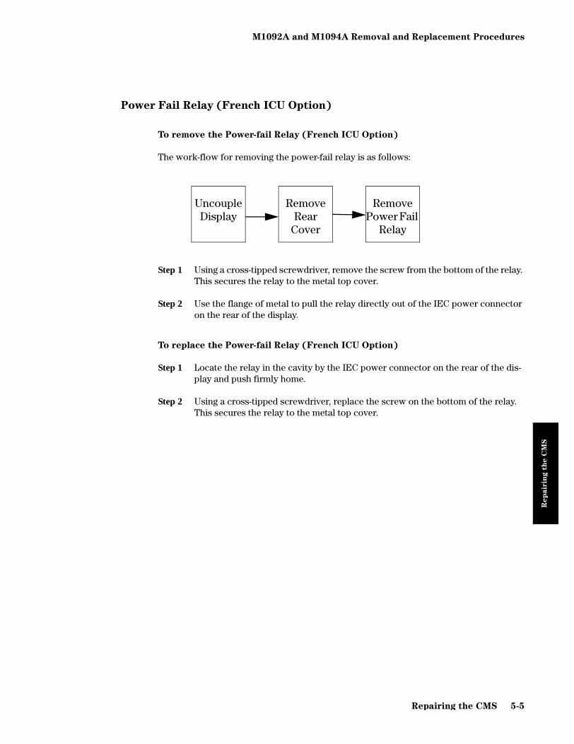
M1092A and M1094A Removal and Replacement Procedures
Rep
air
ing t
he C
MS
Power Fail Relay (French ICU Option)
To remove the Power-fail Relay (French ICU Option)
The work-flow for removing the power-fail relay is as follows:
Step 1 Using a cross-tipped screwdriver, remove the screw from the bottom of the relay. This secures the relay to the metal top cover.
Step 2 Use the flange of metal to pull the relay directly out of the IEC power connector on the rear of the display.
To replace the Power-fail Relay (French ICU Option)
Step 1 Locate the relay in the cavity by the IEC power connector on the rear of the dis-play and push firmly home.
Step 2 Using a cross-tipped screwdriver, replace the screw on the bottom of the relay. This secures the relay to the metal top cover.
Remove Rear
Cover
Remove Power Fail
Relay
Uncouple Display
Repairing the CMS 5-5

M1092A and M1094A Removal and Replacement Procedures
Rep
air
ing t
he C
MS
Power Fuses
To Remove the Power Fuses
No other assemblies need to be removed to remove the Power Fuses.
Step 1 Using a flat-bladed screwdriver, turn the fuse cap a quarter turn counter-clock-wise. The fuse cap should spring slightly from the rear of the display.
Step 2 Pull the fuse cap and fuse clear of the display.
Step 3 Pull the fuse out of the fuse cap and inspect it for a blown condition. If you are unsure, use an ohmmeter to measure the resistance of the fuse. If the fuse reads anything other than a short, the fuse is bad and needs to be replaced.
Step 4 Repeat steps 1 through 3 for the other fuse.
The power fuses
provide over-
voltage protection
to the input line
voltage circuitry.
They are
generally
removed for
inspection. If the
fuses are bad
(blown), they can
only be replaced
by the same type
of fuse with an
identical rating.
Table 1 shows the
fuse ratings.
5-6 Repairing the CMS

M1092A and M1094A Removal and Replacement Procedures
Rep
air
ing t
he C
MS
To replace the Power Fuses
Only use a fuse of the correct rating.
Step 1 Place one end of the fuse, of the correct value, into the fuse cap.
Step 2 Place the fuse and fuse cap into the receptacle in the rear of the display.
Step 3 Using a flat-tipped screwdriver, gently push the fuse cap into the display.
Step 4 Hold the fuse cap into the display and turn the fuse cap a quarter-turn clockwise.
Step 5 Repeat for the other fuse.
Table 5-3 Fuse Ratings for M1092A and M1094A Displays
Display Fuse Part Number
M1092A T4A, UL 110V 242208601263FMI
M1092A T2A, VDE 220V 242208625096FMI
M1092A T2A, UL 220V 242208601266FMI
M1094A T4A, UL 110V 242208601263FMI
M1094A T2.5A, UL 220V 242208610009FMI
M1094A T2.5A, VDE 220V 242208610219FMI
Repairing the CMS 5-7

M1092A and M1094A Removal and Replacement Procedures
Rep
air
ing t
he C
MS
Line Power Filter (M1094A Display)
To remove the Line Power Filter (M1094A Display)
WARNING LETHAL HAZARD FROM ELECTRIC SHOCK
This is part of a filtered power supply. This filter can store lethal voltage levels
for several minutes after the power is removed. You must allow the filter to rest
for at least 10 minutes without power applied before removing it.
You must use a screwdriver with an insulated shaft.
Step 1 Using a cross-tipped screwdriver, remove the two screws from the top and the bottom of the filter cover.
Step 2 Remove the filter cover to expose the filter and its connections. Make a note or sketch of the connections for installing the replacement.
Step 3 Remove the filter connections to the line voltage and the integral switch-mode power supply.
Step 4 While supporting the filter, use the cross-tipped screwdriver to remove the four screws that secure the filter to the display rear enclosure.
Step 5 Lift the filter clear of the display rear enclosure.
To replace the Line Power Filter (M1094A Display)
Step 1 Place the power filter over the four holes on the display rear panel.
Step 2 Support the filter and locate the top screw on each side of the filter.
Step 3 Replace the other two screws and tighten to secure it to the display rear panel.
Step 4 Replace the filter connections as you noted them during the removal.
Step 5 Locate the filter cover over the two holes on the display rear cover.
Step 6 Replace the two screws and tighten to secure the cover in place.
Uncouple Display
Remove Rear
Cover
Remove Line Power
Filter
5-8 Repairing the CMS

M1092A and M1094A Removal and Replacement Procedures
Rep
air
ing t
he C
MS
Rear Enclosure
To remove the Rear Enclosure
Step 1 Using a cross-tipped screwdriver, remove the two screws securing the Rear Enclosure to the display rear panel.
Step 2 Grip the sides of the Rear Enclosure and slide it toward the rear of the display until it stops.
Step 3 Grip the inside lower edges of each side of the Rear Enclosure and spring them outward and lift the Rear Enclosure clear of the display.
To Replace the Rear Enclosure
Step 1 Grip inside the lower edges of each side of the Rear Enclosure, with the back towards you, and spring them outward.
Step 2 Lower the Rear Enclosure over the top of the display module so it is an inch away from the Front Assembly.
Step 3 Grip the sides of the Rear Enclosure and slide it toward the front of the display module until it clicks into place.
Step 4 Using the cross-tipped screwdriver, replace the two screws securing the Rear Enclosure to the display rear panel.
Uncouple Display
Remove Rear
Cover
Remove Rear
Enclosure
.
.
Repairing the CMS 5-9

M1092A and M1094A Removal and Replacement Procedures
Rep
air
ing t
he C
MS
Locking Cam
This is the locking cam which holds the display to the computer module or to a mount.
No other assemblies need to be removed to remove the Locking Cam.
To remove the Locking Cam
Step 1 Lay the display face down on a soft surface.
Step 2 Remove the mounting screw using a number 1 Pozidrive screwdriver. The lock-ing cam can now be removed from the display.
To replace the Locking Cam
Step 1 Lay the display face down on a soft surface.
Step 2 Place the locking cam over the mounting hole so it points toward the rear of the unit.
Step 3 Using a number 1 Pozidrive screwdriver, secure the locking cam to the display with the mounting screw.
REMOVE
5-10 Repairing the CMS

M1092A and M1094A Removal and Replacement Procedures
Rep
air
ing t
he C
MS
Front Assembly
To remove the Front Assembly/Plastic Bezel
Step 1 Place the display module on its back, with its feet toward you.
Step 2 Using the cross-tipped screwdriver, slacken the two securing screws on the bot-tom edge of the Front Assembly.
Step 3 Using a flat-blade screwdriver, spring the plastic tabs toward you and tilt the front of the Front Assembly an inch clear of the screen.
Step 4 Remove the ribbon cable connector from the human interface board in the bot-tom of the Front Assembly. If present, remove the GND cable clamp from the metal cabinet.
Step 5 Lift the Front Assembly clear of the screen.
To replace the Front Assembly
Step 1 Place the display module on its back, with its feet towards you.
Step 2 Locate the four plastic tabs at the top of the Front Assembly into the holes in the top of the display module. Lower the bottom edge of the Front Assembly to within two edges of the screen.
Step 3 Connect the ribbon cable to the human interface board in the bottom of the Front Assembly, noting the orientation of the keyed connector.
Step 4 If present, connect the GND cable clamp to the metal cabinet.
Step 5 Lower the Front Assembly on to the screen, making sure to align the hole in the Front Assembly with the plastic stud of the power switch. Push firmly so the plastic lugs snap on to the display module.
Step 6 Using the cross-tipped screwdriver, tighten the two securing screws on the bot-tom edge of the Front Assembly.
Step 7 Lower the front of the display so that it stands upright.
Uncouple Display
Remove Front Assy
Retain Front
Assembly/Plastic
Bezel if sending
CRT back to the
factory.
Repairing the CMS 5-11
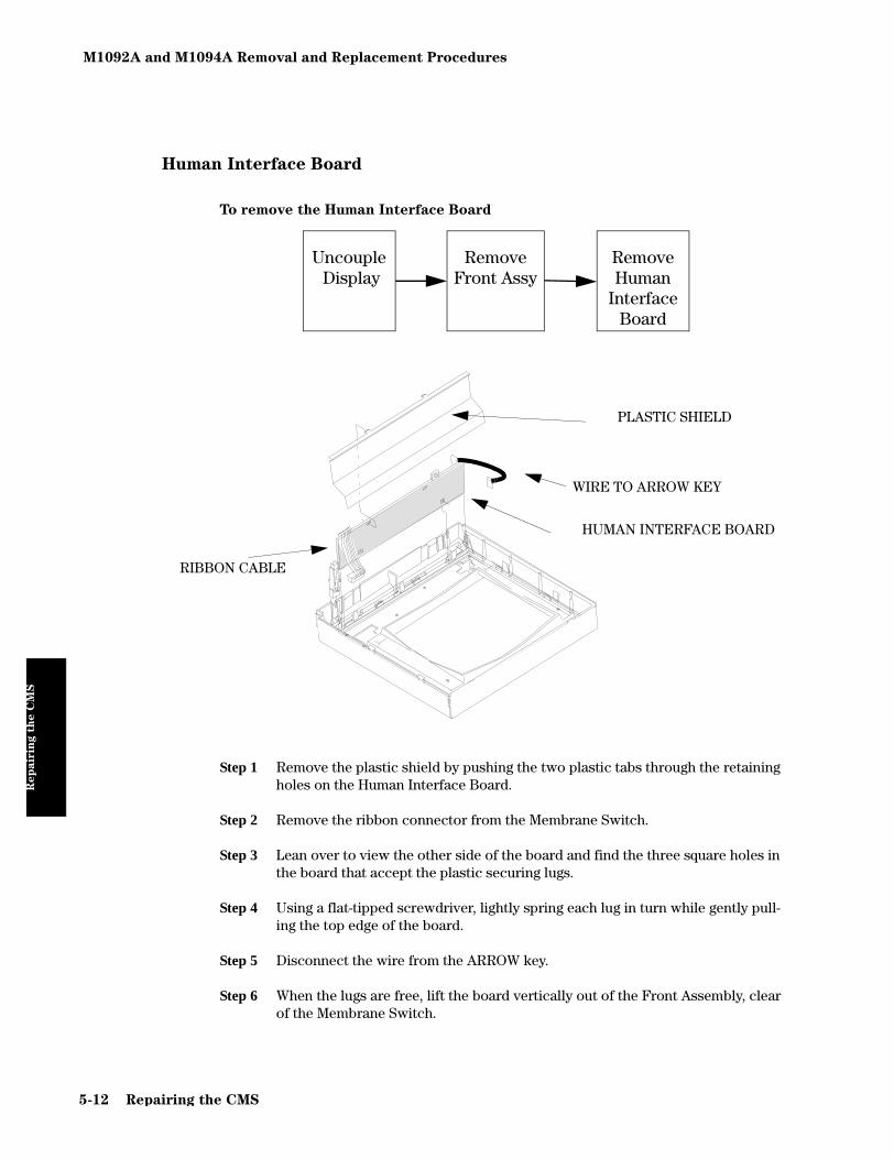
M1092A and M1094A Removal and Replacement Procedures
Rep
air
ing t
he C
MS
Human Interface Board
To remove the Human Interface Board
Step 1 Remove the plastic shield by pushing the two plastic tabs through the retaining holes on the Human Interface Board.
Step 2 Remove the ribbon connector from the Membrane Switch.
Step 3 Lean over to view the other side of the board and find the three square holes in the board that accept the plastic securing lugs.
Step 4 Using a flat-tipped screwdriver, lightly spring each lug in turn while gently pull-ing the top edge of the board.
Step 5 Disconnect the wire from the ARROW key.
Step 6 When the lugs are free, lift the board vertically out of the Front Assembly, clear of the Membrane Switch.
Uncouple Display
Remove Front Assy
Remove Human
Interface Board
PLASTIC SHIELD
RIBBON CABLE
WIRE TO ARROW KEY
HUMAN INTERFACE BOARD
5-12 Repairing the CMS

M1092A and M1094A Removal and Replacement Procedures
Rep
air
ing t
he C
MS
To replace the Human Interface Board
Step 1 Locate the lower edge of the interface board into the slots on either side of the Front Assembly.
Step 2 Align the LED with the hole in the Front Assembly, as you place the board into the slots.
Step 3 Push the board firmly so the three plastic lugs engage.
Step 4 Reconnect the ribbon connector into the Membrane Switch.
Step 5 Reconnect the wire to the ARROW key.
Step 6 Align the plastic tabs of the plastic shield with the retaining holes on the Human Interface Board and push the plastic shield until it snaps into place.
Membrane Switch
To remove the Membrane Switch
UncoupleDisplay
Remove Front
Assembly
Remove Human
Interface Board
RemoveMembrane
Switch
MEMBRANE KEYPAD
SIX PUSH-IN RETAINERS
Repairing the CMS 5-13

M1092A and M1094A Removal and Replacement Procedures
Rep
air
ing t
he C
MS
Step 1 Remove the ribbon cable from the keypad.
Step 2 Lay the Front Assembly flat on a table with the back of the Front Assembly uppermost.
Step 3 Using the screwdriver, remove the six push-in retainers.
Step 4 While pushing on the central threaded post, lift the Front Assembly clear of the keypad.
To replace the Membrane Switch
Step 1 Lay the keypad on a table with the threaded post facing up.
Step 2 Lower the threaded posts through the holes in the Front Assembly.
Step 3 Replace the six push-in retainers. These secure the keypad to the Front Assem-bly.
Step 4 Connect the ribbon cable to the keypad.
Metal Cover
The Metal Cover is not a field replaceable assembly. Its removal and replacement is included here because it must be removed to remove other assemblies internal to the display.
To remove the Metal Cover
UncoupleDisplay
Remove Rear
Cover
Remove Rear
Enclosure
Remove Metal Cover
5-14 Repairing the CMS

M1092A and M1094A Removal and Replacement Procedures
Rep
air
ing t
he C
MS
Step 1 Using a cross-tipped screwdriver, remove the eight screws securing the metal cover to the display.
Step 2 For the M1094A (color) display, lift the top of the cover and pass the connector to the line filter through the holes in the rear of the cover.
Step 3 Lift the cover from the display.
To replace the Metal Cover
Step 1 For the M1094A (color), support the cover to the rear of the display and pass the connectors to the line filter through the holes in the rear of the cover. The three connectors from the main inlet connector are passed through the left hole and the two load connectors to the SMPS are passed through the lower right hole.
Step 2 Locate the cover on the display so the holes in the cover and display are aligned.
Step 3 Replace the eight screws to secure the cover to the display.
Repairing the CMS 5-15

M1092A and M1094A Removal and Replacement Procedures
Rep
air
ing t
he C
MS
Fuse Assembly
To remove the Fuse Assembly
Step 1 Using a cross-tipped screwdriver, remove the two screws securing the two green and yellow striped wires from the switch-mode power supply and deflection board to the common ground point on the plate of the assembly. Note there are two washers for each lead, one below and one above the lead.
Step 2 Remove the screw securing the single grounding wire to the common ground point.
Step 3 For the M1092A (monochrome) display only, remove the power connection from the rear of the SMPS.
Step 4 For the M1092A (monochrome) display only, go to the front of the display and, using a cross-tipped screwdriver, remove the two screws securing the power switch to the left of the display front panel.
For the M1092A
Display, the power
connector and the
power switch are
part of the fuse
assembly. They are
removed when the
fuse assembly is
removed. The
power connector is
not a field
replaceable item so
there is no further
maintenance on it.
UncoupleDisplay
Remove Rear
Cover
Remove Rear
Enclosure
RemoveMetalCover
Remove Fuse
Assembly
.
REMOVE 2
SCREWS
5-16 Repairing the CMS

M1092A and M1094A Removal and Replacement Procedures
Rep
air
ing t
he C
MS
Step 5 Pass the power switch into the body of the display and pull it out from the rear of the display.
Step 6 Remove the screw on the left of the grounding post on the rear of the SMPS. This secures the assembly to the power supply.
Step 7 Slide the assembly out of the slot in the side of the power supply.
To replace the Fuse Assembly
Step 1 Slide the assembly into the two slots on the right side of the SMPS.
Step 2 Secure the assembly to the SMPS using one screw.
Step 3 For the M1092A (monochrome) display only, pass the power switch from the rear of the display to the left of the front panel.
Step 4 For the M1092A (monochrome) display only, at the front of the display, use a cross-tipped screwdriver to secure the power switch to the display front panel using two screws.
Step 5 For the M1092A (monochrome) display only, connect the power connector to the rear of the SMPS.
Step 6 Secure the single grounding wire to the common ground point using one screw.
Step 7 Secure the two green and yellow wires from the SMPS and the deflection board to the common ground point using one screw and two washers for each lead. One washer goes above the lead and one washer goes beneath the lead.
Repairing the CMS 5-17

M1092A and M1094A Removal and Replacement Procedures
Rep
air
ing t
he C
MS
Switch-Mode Power Supply (M1092A)
To remove Switch-Mode Power Supply (SMPS)
Step 1 Remove the power connector (red and black wires) for the human interface board from the top of the SMPS.
Step 2 Remove the power connector (orange and black wires) for the deflector board from the top of the SMPS.
Step 3 Remove the black wire for from the plug-in spade terminals on the SMPS cover.
Step 4 Using a cross-tipped screwdriver, remove the two screws from the outside of the display’s left panel. These screws secure the SMPS to the display module.
Step 5 Slide the SMPS toward the rear of the display to access the power connector on the front of the SMPS. Disconnect the connector.
Step 6 Lift the SMPS from the display.
UncoupleDisplay
Remove Rear
Cover
Remove Rear
Enclosure
RemoveMetal Cover
Remove SMPS
5-18 Repairing the CMS

M1092A and M1094A Removal and Replacement Procedures
Rep
air
ing t
he C
MS
To replace the SMPS
Step 1 Hold the SMPS with the 15-pin D-type connector toward you and the open part of the SMPS case to your left.
Step 2 Place the SMPS into the display module so that you can make the power connec-tion on the front side of the SMPS.
Step 3 Connect the connector to the plug on the front side of the SMPS.
Step 4 Slide the SMPS into the slot on the left side of the main casing of the display module. The holes in the SMPS and the left panel of the display module should be aligned.
Step 5 Using a cross-tipped screwdriver, secure the SMPS to the display’s left panel using two screws.
Step 6 Connect the black wires to the plug-in spade terminals on the SMPS.
Step 7 Connect the power connector (orange and black wires) for the deflector board to the top of the SMPS.
Step 8 Connect the power connector (red and black wires) for the human interface board to the top of the SMPS.
WARNING When you remove or replace a power supply, you MUST perform the required
safety test(s) before the equipment is used again for monitoring.
See Chapter 2 for details of the safety tests.
Repairing the CMS 5-19
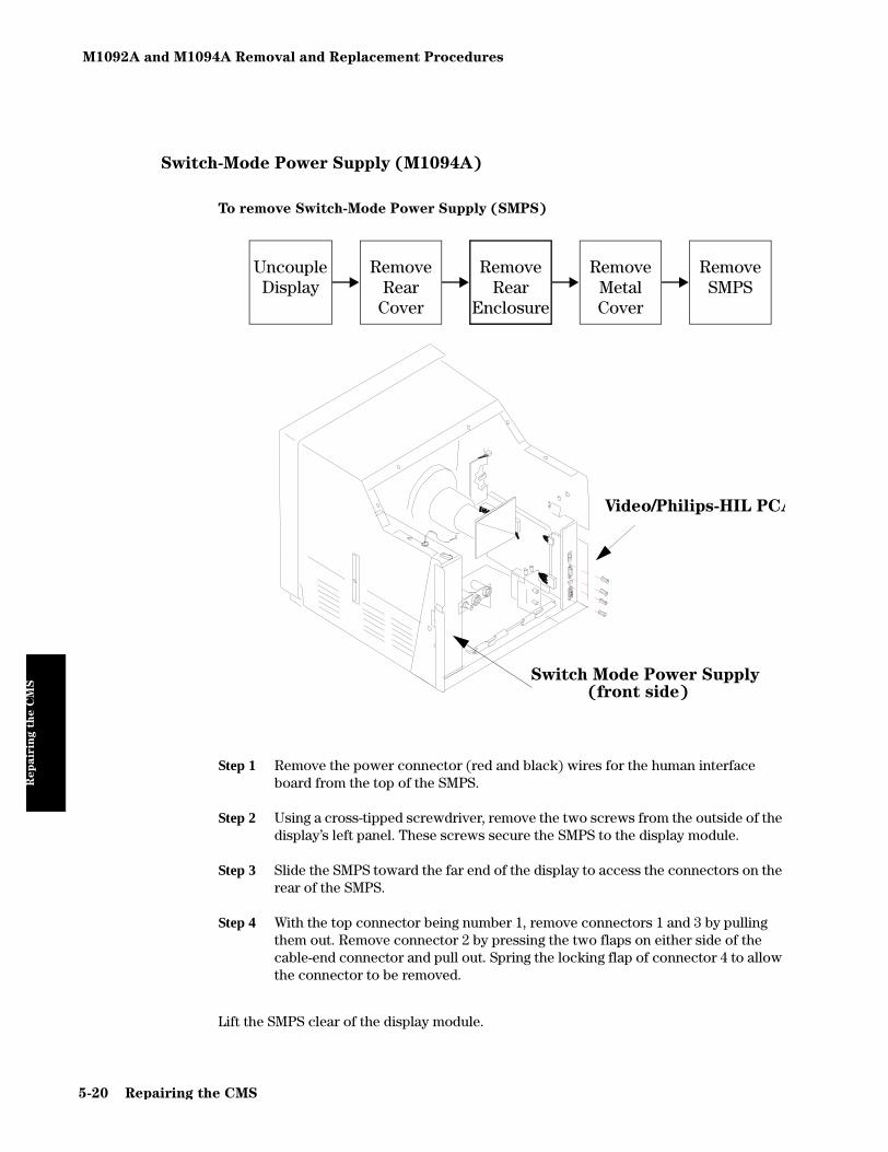
M1092A and M1094A Removal and Replacement Procedures
Rep
air
ing t
he C
MS
Switch-Mode Power Supply (M1094A)
To remove Switch-Mode Power Supply (SMPS)
Step 1 Remove the power connector (red and black) wires for the human interface board from the top of the SMPS.
Step 2 Using a cross-tipped screwdriver, remove the two screws from the outside of the display’s left panel. These screws secure the SMPS to the display module.
Step 3 Slide the SMPS toward the far end of the display to access the connectors on the rear of the SMPS.
Step 4 With the top connector being number 1, remove connectors 1 and 3 by pulling them out. Remove connector 2 by pressing the two flaps on either side of the cable-end connector and pull out. Spring the locking flap of connector 4 to allow the connector to be removed.
Lift the SMPS clear of the display module.
UncoupleDisplay
Remove Rear
Cover
Remove Rear
Enclosure
RemoveMetalCover
Remove SMPS
Video/Philips-HIL PCA
Switch Mode Power Supply(front side)
5-20 Repairing the CMS

M1092A and M1094A Removal and Replacement Procedures
Rep
air
ing t
he C
MS
To Replace the SMPS
Step 1 Hold the SMPS with the 15-pin D-type connector toward you and the open part of the SMPS case to your left.
Step 2 Place the SMPS into the display module so that you can make the connection on the front side of the SMPS.
Step 3 Replace the connectors by pushing them in receptacles of the correct color and shape.
Step 4 Place the SMPS in the display so the holes in both the SMPS and the left panel of the display are aligned.
Step 5 Using a cross-tipped screwdriver, secure the SMPS to the display’s left panel using two screws.
Step 6 Connect the power connector (red and black wires) for the human interface board to the top of the SMPS.
WARNING When you remove or replace a power supply, you MUST perform the required
safety test(s) before the equipment is used again for monitoring.
See Chapter 2 for details of the safety tests.
Repairing the CMS 5-21

M1092A and M1094A Removal and Replacement Procedures
Rep
air
ing t
he C
MS
Video/Philips-HIL Connector PCA
To remove the Video/Philips-HIL Connector PCA
See previous graphic to locate the Video/Philips-HIL Connector PCA
Step 1 Unplug the two connectors from the video card.
Step 2 Using a socket driver, remove the four hex studs from the plate.
Step 3 Lift the connector plate clear of the display.
To replace the Video/Philips-HIL Connector PCA
Step 1 Place the connector plate over the four mounting holes.
Step 2 Using a socket driver, secure the plate using the four hex studs.
Step 3 Plug the two connectors to the video card.
UncoupleDisplay
Remove Rear
Cover
Remove Rear
Enclosure
RemoveMetalCover
Remove Video/Phil-
ips-HIL
5-22 Repairing the CMS

M1094B Removal and Replacement Procedures
Rep
air
ing t
he C
MS
M1094B Removal and Replacement Procedures
The following procedures apply for the M1094B (color) monitor.
Rear Cover
To remove the Rear Cover
You do not need any special tools to remove the rear cover. It can be removed using a cross-tipped screwdriver.
No other assemblies need to be removed to remove the rear cover.
Step 1 Slide the two spring locks toward the center of the cover and lift the lower edge of the cover.
Step 2 Raise the cover so it is horizontal and slide the cover directly out of the rear of the display.
Step 3 Lean the cover against the side of the display such that you can see the ground connection to the case.
Uncouple Display
Remove Rear
Cover
5-23

M1094B Removal and Replacement Procedures
Rep
air
ing t
he C
MS
Step 4 Lean the cover against the side of the display such that you can see the ground connection to the case.Using a cross-tipped screwdriver, remove the large grounding screw from the inside of the display's left panel. Make sure that you retain the two washers.
To replace the Rear Cover
Step 1 Lean the cover against the rear of the display such that you can connect the ground wire to the case of the display.
Step 2 Using a cross-tipped screwdriver, replace the large grounding screw on the inside of the display's left panel. Make sure that you replace the two washers on either side of the cable eyelet.
Step 3 Holding the cover horizontally, slide the cover into the top of the display and lower the free edge of the cover to the vertical.
Step 4 Push the bottom of the cover firmly into place and the two spring locks “click” to lock the cover into place.
Power Fuses
To Remove the Power Fuses
The power fuses provide over-voltage protection to the input line voltage circuitry. They are generally removed for inspection purposes. If the fuses are bad (blown), they can only be replaced by the same type of fuse with an identical rating. The fuses are removed using a flat-bladed screwdriver.
FUSES
The power fuses
provide over-
voltage protection
to the input line
voltage circuitry.
They are
generally
removed for
inspection. If the
fuses are bad
(blown), they can
only be replaced
by the same type
of fuse with an
identical rating.
Table 2 shows the
fuse ratings for
the M1094B.
5-24

M1094B Removal and Replacement Procedures
Rep
air
ing t
he C
MS
Step 1 Using a flat-bladed screwdriver, turn the fuse cap a quarter turn counter-clock-wise. The fuse cap should spring slightly from the rear of the display.
Step 2 Pull the fuse cap and fuse clear of the display.
Step 3 Pull the fuse out of the fuse cap and inspect it for a blown condition. If you are unsure, use an ohmmeter to measure the resistance of the fuse. If the fuse reads anything other than a short, the fuse is bad and needs to be replaced.
Step 4 Repeat steps 1 through 3 for the other fuse.
To replace the Power Fuses
Only use a fuse of the correct rating.
Step 1 Locate one end of the fuse of the correct value into the fuse cap.
Step 2 Locate the fuse and fuse cap into the receptacle in the rear of the display.
Step 3 Using a flat-tipped screwdriver, gently push the fuse cap into the display.
Step 4 Hold the fuse cap into the display and turn the fuse cap a quarter-turn clockwise.
Step 5 Repeat for the other fuse.
Table 5-4 Fuse Ratings for M1094B Display
Display Fuse Part Number
M1094B T4A, UL 110V 242208601263FMI
M1094B T3.15A, VDE or UL 220V 242208610239FMI
5-25

M1094B Removal and Replacement Procedures
Rep
air
ing t
he C
MS
Rear Enclosure
To remove the Rear Enclosure
Step 1 Using a cross-tipped screwdriver, remove the two screws securing the Rear Enclosure to the display rear panel.
Step 2 Grip the sides of the Rear Enclosure and slide it towards the rear of the display until it stops.
Step 3 Grip the inside lower edges of each side of the Rear Enclosure and spring them outward and lift the Rear Enclosure clear of the display.
To replace the Rear Enclosure
Step 1 Grip inside the lower edges of each side of the Rear Enclosure, with the back towards you, and spring them outward.
Step 2 Lower the Rear Enclosure over the top of the display module so it is an inch away from the front Front Assembly.
Step 3 Grip the sides of the Rear Enclosure and slide it toward the front of the display module until it clicks into place.
Step 4 Using the cross-tipped screwdriver, replace the two screws securing the Rear Enclosure to the display rear panel.
Uncouple Display
Remove Rear
Cover
Remove Rear
Enclosure
5-26

M1094B Removal and Replacement Procedures
Rep
air
ing t
he C
MS
Locking Cam
This is the locking cam which holds the display to the computer module or to a mount.
To remove the Locking Cam
Step 1 Lay the display face down on a soft surface.
Step 2 Remove the mounting screw using a number 1 Pozidrive screwdriver. The lock-ing cam can now be removed from the display.
To replace the Locking Cam
Step 1 Lay the display face down on a soft surface.
Step 2 Place the locking cam over the mounting hole so it points towards the rear of the unit.
Step 3 Using a number 1 Pozidrive screwdriver, secure the locking cam to the display with the mounting screw.
REMOVE
5-27

M1094B Removal and Replacement Procedures
Rep
air
ing t
he C
MS
Front Assembly
To remove the Front Assembly
Step 1 Place the display module on its back, with its feet towards you.
Step 2 Using the cross-tipped screwdriver, slacken the two securing screws on the bot-tom edge of the Front Assembly.
Step 3 Using a flat-blade screwdriver, spring the plastic tabs towards you and tilt the front of the Front Assembly an inch clear of the screen.
Step 4 Remove the ribbon cable connector from the human interface board in the bot-tom of the Front Assembly. If present, remove the GND cable clamp from the metal cabinet.
Step 5 Lift the Front Assembly clear of the screen.
To replace the Front Assembly
Step 1 Place the display module on its back, with its feet towards you.
Step 2 Locate the four plastic tabs at the top of the Front Assembly into the holes in the top of the display module. Lower the bottom edge of the Front Assembly to within two edges of the screen.
Step 3 Connect the ribbon cable to the human interface board in the bottom of the Front Assembly, noting the orientation of the keyed connector.
Step 4 If present, connect the GND cable clamp to the metal cabinet.
Step 5 Lower the Front Assembly onto the screen, making sure to align the hole in the Front Assembly with the plastic stud of the power switch. Push firmly so the plastic lugs snap on to the display module.
Step 6 Using the cross-tipped screwdriver, tighten the two securing screws on the bot-tom edge of the Front Assembly.
Step 7 Lower the front of the display so that it stands upright.
Uncouple Display
Remove Front Assy
5-28

M1094B Removal and Replacement Procedures
Rep
air
ing t
he C
MS
Human Interface Board
To remove the Human Interface Board
Step 1 Remove the plastic shield by pushing the two plastic tabs through the retaining holes on the Human Interface Board.
Step 2 Lay the Front Assembly face-down so you have the Human Interface Board toward you.
Step 3 Remove the ribbon connector from the Membrane Switch.
Step 4 Lean over to view the other side of the board and find the two square holes in the board that accept the plastic securing lugs.
Step 5 Using a flat-tipped screwdriver, lightly spring each lug in turn while gently pull-ing the top edge of the board.
Step 6 Disconnect the wire from the ARROW key.
Step 7 When both lugs are free, lift the board vertically out of the Front Assembly.
Uncouple Display
Remove Front Assy
Remove Human
Interface Board
PLASTIC SHIELD
RIBBON CABLE
WIRE TO ARROW KEY
HUMAN INTERFACE BOARD
5-29

M1094B Removal and Replacement Procedures
Rep
air
ing t
he C
MS
To replace the Human Interface Board
Step 1 Locate the lower edge of the interface board into the slots on either side of the Front Assembly.
Step 2 Align the LED with the hole in the Front Assembly, as you place the board into the slots.
Step 3 Push the board firmly so that the two plastic lugs engage.
Step 4 Reconnect the ribbon connector into the Membrane Switch.
Step 5 Reconnect the wire to the ARROW key.
Step 6 Align the plastic tabs of the plastic shield with the retaining holes on the Human Interface Board and push the plastic shield until it snaps into place.
Membrane Switch
To remove the Membrane Switch
Step 1 Remove the ribbon cable from the keypad.
Step 2 Lay the Front Assembly flat on a table with the back of the Front Assembly uppermost.
UncoupleDisplay
Remove Front
Assembly
Remove Human
Interface Board
RemoveMembrane
Switch
MEMBRANE KEYPAD
SIX PUSH IN RETAINERS
5-30
M1094B Removal and Replacement Procedures
Rep
air
ing t
he C
MS
Step 3 Using the screwdriver, remove the six push-in retainers.
Step 4 While pushing on the central threaded post, lift the Front Assembly clear of the keypad.
To replace the Membrane Switch
Step 1 Lay the keypad on a table with the threaded post facing up.
Step 2 Lower the Front Assembly so that the threaded posts pass through the holes in the Front Assembly.
Step 3 Replace the six push-in retainers. These secure the keypad to the Front Assem-bly.
Step 4 Connect the ribbon cable to the keypad.
5-31

M1094B Removal and Replacement Procedures
Rep
air
ing t
he C
MS
Top Metal Cover and SMPS Cover
The Top Metal Cover and the SMPS Cover are not field replaceable assemblies. Their removal and replacement are included here because they must be removed to remove other assemblies internal to the display.
To remove the Metal Cover
Step 1 Using a cross-tipped screwdriver, remove the 11 screws securing the metal cover and the SMPS cover to the display.
Step 2 Remove the Top Metal and SMPS covers from the display.
To replace the Top Metal Cover and the SMPS Cover
Step 1 Insert the SMPS cover over the rear of the display. Slide the bottom and sides into place and align the 2 screw holes on the cover’s top edge with holes in the top frame of display.
Step 2 Insert the three tabs on the top metal cover into slots on top of the display, and align the cover’s screw holes with holes in the display frame and bottom cover.
Step 3 Secure the Top Metal Cover and SMPS cover to the display using 11 screws.
expmetal.mif
5-32

M1094B Removal and Replacement Procedures
Rep
air
ing t
he C
MS
Switch-Mode Power Supply
To remove Switch-Mode Power Supply (SMPS)
Step 1 Disconnect the line switch assembly on the lower right of the SMPS by pressing its top and removing its bottom tab from the connector slot. Push the assembly and cable through the hole in the SMPS.
Step 2 Disconnect the remaining four cables entering the rear of the SMPS.
Step 3 Remove the six screws securing the SMPS to the rear of the display.
Step 4 Remove the ground wire from the bottom front of the SMPS by removing one screw.
Step 5 Using a flat-bladed screwdriver, press the two white tabs (top center and right center), tilt the SMPS forward, and remove the SMPS.
To Replace the SMPS
Step 1 Place the SMPS tab holes over the two white tabs and snap into place.
Step 2 Secure the ground wire to the bottom front of the SMPS using one screw.
Step 3 Align the screw holes and secure the SMPS to the rear of the display using six screws.
Step 4 Connect the four cables to the rear of the SMPS.
Step 5 Connect the line switch assembly to the SMPS.
WARNING When you remove or replace a power supply, you MUST perform the required
safety test(s) before the equipment is used again for monitoring.
See Chapter 2 for details of the safety tests.
DEPRESS TABS
5-33

M1095A Backlight Removal and Replacement Procedures
Rep
air
ing t
he C
MS
M1095A Backlight Removal and Replacement Procedures
NOTE It is recommended that the fluorescent tube (“backlight”) in the display module be replaced after a certain time, which depends on the type of display (see Table below)If an unacceptable decrease in backlight intensity is noted the fluorescent tube has to be replaced as well.
CAUTION If dirt or dust gets on the fluorescent lamp in the lamp holder during
replacement, brightness variations might occur. Therefore, we recommend the
use of a clean room or clean bench (at the class C level).
In addition, the LCD module can be destroyed by static electricity. Therefore, we
recommend the use of an ionizer (ion shower).
NOTE There are two different backlight replacement procedures depending on what type of M1095A Display you have.The first procedure applies for the Old-Color type display and starts from page 5-35.The second procedure for the New-Color type display starts from page 5-38.
Table 5-5 M1095A Flatscreen Display Backlight Lifetimes
M1095A
s/n prefix
LCD Type
(inside)
Backlight
p/n
Lifetime
(months)
< 3805G AC33-10 2090-0546 14
3805G AC33-24 2090-0360 34
3923G AC33-29 2090-0381 64
5-34

M1095A Backlight Removal and Replacement Procedures
Rep
air
ing t
he C
MS
Backlight replacement procedure for M1095A Old-Color Version
To remove rear housing
Step 1 Separate display from mounting hardware and place the display face down on the bench.
Step 2 Remove the four screws holding the rear housing in place using a number 1 Pozidrive screwdriver.
Step 3 Lift the left-hand side of the rear housing and open carefully, pivoting on the right-hand side (where the On/Off switch is).
Step 4 Before placing the rear housing on the bench, remove the ribbon cable connec-tor (gray) from the socket (black) on the board in the bottom of the front assem-bly.
Step 5 Disconnect the remaining connector from the rear housing, pushing the clips to the side to release the connector.
5-35

M1095A Backlight Removal and Replacement Procedures
Rep
air
ing t
he C
MS
To remove screen assembly from front housing
Step 1 Using a number 1 Pozidrive screwdriver, remove the four screws holding the metal plate.
Step 2 Holding the metal plate in place, lift the entire assembly and place it face up on the bench.
NOTE For all further steps, wear gloves to avoid skin contact with the screen surface.
Step 3 Lift the front housing off the screen assembly.
CAUTION Do not touch the screen surface.
Step 4 Using a Pozidrive number 1 screwdriver, remove the four large screws holding the screen onto the metal plate.
Step 5 Lift the screen assembly off the metal plate and lay it face down on the clean bench.
5-36

M1095A Backlight Removal and Replacement Procedures
Rep
air
ing t
he C
MS
To remove backlight assembly
Step 1 Pull out cable holder to release flat cable and disconnect.
Step 2 Using round-tipped tweezers, release the lamp cables from the cable channel.
Step 3 Using a small cross-tipped screwdriver, remove the two screws holding the inverter board.
Step 4 Slip the inverter board out from beneath the two plastic retaining tabs.
Step 5 Unplug lamp cables from inverter board.
Step 6 Using a small cross-tipped screwdriver, remove retaining screw on backlight.
Step 7 Using the lamp cables, pull gently and in a straight line on the backlight assembly to remove it.
5-37

M1095A Backlight Removal and Replacement Procedures
Rep
air
ing t
he C
MS
Backlight replacement procedure for M1095A New-Color Version
To remove rear housing
Step 1 Separate display from mounting hardware and place the display face down on the bench.
Step 2 Remove the four screws holding the rear housing in place using a number 1 Pozidrive screwdriver.
Step 3 Lift the left-hand side of the rear housing and open carefully, pivoting on the right-hand side (where the On/Off switch is).
Step 4 Before placing the rear housing on the bench, remove the ribbon cable connec-tor (gray) from the socket (black) on the board in the bottom of the front assem-bly.
Step 5 Remove the two crosshead screws securing the ferrite bead clamp and lift it clear of the video cable.
Step 6 Disconnect the video cable from the connector on the video board.
5-38

M1095A Backlight Removal and Replacement Procedures
Rep
air
ing t
he C
MS
To remove LCD panel from front housing
Step 1 Using a number 1 Pozidrive screwdriver, remove the four screws holding the metal plate.
Step 2 Holding the metal plate in place, lift the entire assembly and place it face up on the bench.
NOTE For all further steps, wear gloves to avoid skin contact with the screen surface.
Step 3 Lift the front housing off the screen assembly.
CAUTION Do not touch the screen surface.
Step 4 Using a Pozidrive number 1 screwdriver, remove the two right-hand screws and loosen the two left-hand screws that hold the screen onto the metal plate.
Removescrews
Remove screws
Loosen screws
5-39

M1095A Backlight Removal and Replacement Procedures
Rep
air
ing t
he C
MS
To remove backlight assembly
Step 1 Move the LCD panel 5cm to the left to expose the inverter board.
Step 2 Unplug backlight connector from inverter board.
Step 3 Look on the edge of the LCD panel and raise the locking clip to release the back-light.
Step 4 Using the lamp cables, pull the backlight gently and in a straight line out of the LCD panel.
Inverter board
Backlight connector
Locking Clip
Backlight
Lamp cables
5-40

Handheld Keypad
Rep
air
ing t
he C
MS
Handheld Keypad
The following is a list of replaceable parts for the handheld keypad.
Housing Assembly
To Remove the Housing Assembly
Step 1 Place the handheld keypad face down on a table.
Step 2 Using a cross-tipped screwdriver, remove the 7 screws from the bottom cover.
Step 3 Remove the keypad bottom cover.
Replaceable Part
Housing Assembly (includes top cover, bottom cover, magnet, rubber feet, and screws)
Board Assembly (includes switch board and logic board assembly)
Cable Assembly
5-41

Handheld Keypad
Rep
air
ing t
he C
MS
Step 4 To remove the rubber feet, push the feet through the holes in the bottom cover from the inside.
Step 5 Lift the printed circuit boards out of the housing assembly to expose the top cover.
To Replace the Housing Assembly
Step 1 If the rubber feet have been removed, replace them by pushing the stubs through the holes in the bottom cover from the outside.
Step 2 Place the bottom cover on a table with the magnet side down.
Step 3 Place the printed circuit boards (with the keys facing up) in the bottom cover, such that the standoffs on the bottom cover fit through the holes in the logic board.
Step 4 Dress the cable through the strain relief and out through the bottom cover.
Step 5 Replace the top cover and turn the keypad over.
Step 6 Using a cross-tipped screwdriver, replace the 7 screws.
Step 7 If you are replacing the housing assembly with a new one, peel the serial number off of the old housing assembly and affix it to the new one.
5-42
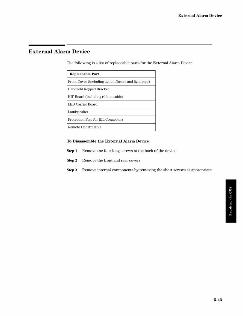
External Alarm Device
Rep
air
ing t
he C
MS
External Alarm Device
The following is a list of replaceable parts for the External Alarm Device.
To Disassemble the External Alarm Device
Step 1 Remove the four long screws at the back of the device.
Step 2 Remove the front and rear covers.
Step 3 Remove internal components by removing the short screws as appropriate.
Replaceable Part
Front Cover (including light diffusers and light pipe)
Handheld Keypad Bracket
HIF Board (including ribbon cable)
LED Carrier Board
Loudspeaker
Protection Flap for HIL Connectors
Remote On/Off Cable
5-43

Computer Module Removal and Replacement
Rep
air
ing t
he C
MS
Computer Module Removal and Replacement
The following is a list of replaceable parts for the Computer Module. These descriptions apply equally to the M1046A Computer Module and the new M1046B Computer Module. Where a procedure or certain steps within a procedure apply to only either the M1046A or M1046B it will be labeled as either M1046A only or M1046B only.
Replaceable Part Page
Rear Cover 5-45
DC/DC Converter 5-46
Integral Rack - M1046A only 5-47
Front Plastic Cover - M1046B only 5-48
Integral Power Supply - M1046B only 5-49
Sheet Metal Cover - M1046B only 5-51
Front Function Card 5-51
Rear Function Cards 5-54
Side Cover 5-56
Top Cover 5-57
Backplane Board Assy 5-58
Plastic Feet 5-59
Locking CAM 5-60
5-44
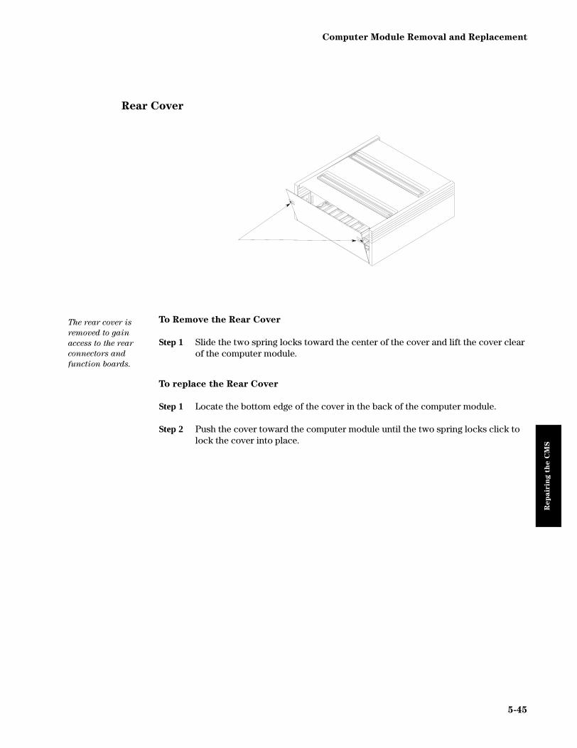
Computer Module Removal and Replacement
Rep
air
ing t
he C
MS
Rear Cover
To Remove the Rear Cover
Step 1 Slide the two spring locks toward the center of the cover and lift the cover clear of the computer module.
To replace the Rear Cover
Step 1 Locate the bottom edge of the cover in the back of the computer module.
Step 2 Push the cover toward the computer module until the two spring locks click to lock the cover into place.
The rear cover is
removed to gain
access to the rear
connectors and
function boards.
5-45

Computer Module Removal and Replacement
Rep
air
ing t
he C
MS
DC/DC Converter
The work-flow for removing the DC/DC converter is as follows:
To Remove the DC/DC Converter
Step 1 Remove the power input cable (60 V) from the rear of the DC/DC converter.
Step 2 Using a cross-tipped screwdriver, remove the screw that secures the top edge of the DC/DC converter to the computer module.
Step 3 Grip the metal heat sink of the DC/DC converter and slide it out horizontally until it is completely clear of the computer module.
To Replace the DC/DC Converter
Step 1 Locate the card-edge of the DC/DC converter into the far left slot in the rear of the computer module.
Step 2 Slide the DC/DC converter into the computer module until it locates into the con-nector on the centre board and firmly seat it into the connector.
Step 3 Replace the screw on the top edge of the DC/DC converter and tighten using a cross-tipped screwdriver.
NOTE When you replace the DC/DC converter on a M1046B, the shorting stub from the old one MUST be replaced in the connector or the system will not function correctly.
The DC/DC
Converter is
secured to the top
cover of the outer
casing and must
be removed to
gain access to the
centre plane of
the computer
module.
Remove Rear Cover
Remove DC/DC
Converter
RDCDC
5-46

Computer Module Removal and Replacement
Rep
air
ing t
he C
MS
Integral Rack - M1046A only
To Remove the Integral Rack
Step 1 Stand in front of the computer module with the integral rack facing you.
Step 2 Press the tabs on the lower side edge of the integral rack and slide the rack gen-tly towards you until it clears the computer module.
To Replace the Integral Rack
Step 1 Locate the two large tabs inside the cavity of the computer module.
Step 2 Gently slide the integral rack into the computer module until the securing tabs on either side of the computer module engage. Check that the rack is secure.
The integral rack
holds the plug-in
modules. It must
be removed to
gain access to the
CPC Flash
connector and the
other front
function cards.
INTEGRAL RACK
5-47

Computer Module Removal and Replacement
Rep
air
ing t
he C
MS
Front Plastic Cover - M1046B only
To Remove the Plastic Front Cover
Step 1 Stand in front of the computer module with the integral rack facing you.
Step 2 Grip the Plastic Cover firmly on each side and pull directly towards you.
To Replace the Plastic Front Cover
Step 1 Align the four posts on the inside of the plastic cover with those on the computer module.
Step 2 Firmly push the plastic cover, on each side, so that the cover posts fit over the computer module posts.
Power Fuses
To Remove the Power Fuses
The plastic front cover needs to be removed to remove the Power Fuses.
Step 1 Using a flat-bladed screwdriver, turn the fuse cap a quarter turn counter-clock-wise. The fuse cap should spring slightly from the rear of the display.
Step 2 Pull the fuse cap and fuse clear of the display.
Step 3 Pull the fuse out of the fuse cap and inspect it for a blown condition. If you are unsure, use an ohmmeter to measure the resistance of the fuse. If the fuse reads anything other than a short, the fuse is bad and needs to be replaced.
Step 4 Repeat steps 1 through 3 for the other fuse.
The power fuses
provide over-
voltage protection
to the input line
voltage circuitry.
They are
generally
removed for
inspection. If the
fuses are bad
(blown), they can
only be replaced
by the same type
of fuse with an
identical rating.
Table
6-3 shows the
fuse ratings.
5-48

Computer Module Removal and Replacement
Rep
air
ing t
he C
MS
To replace the Power Fuses
Only use a fuse of the correct rating.
Step 1 Place one end of the fuse, of the correct value, into the fuse cap.
Step 2 Place the fuse and fuse cap into the receptacle in the rear of the display.
Step 3 Using a flat-tipped screwdriver, gently push the fuse cap into the display.
Step 4 Hold the fuse cap into the display and turn the fuse cap a quarter-turn clockwise.
Step 5 Repeat for the other fuse.
Integral Power Supply - M1046B only
To Remove the Integral Power Supply
Step 1 Use a cross-tipped screwdriver to undo the two captive screws that secure the power supply to the computer module, slide the power supply to the right and remove from the sheet metal cover.
Table 5-6 Fuse Ratings for the M1046B
Display Fuse Part Number
M1046B T3.15H, 250V 2110-1025
5-49
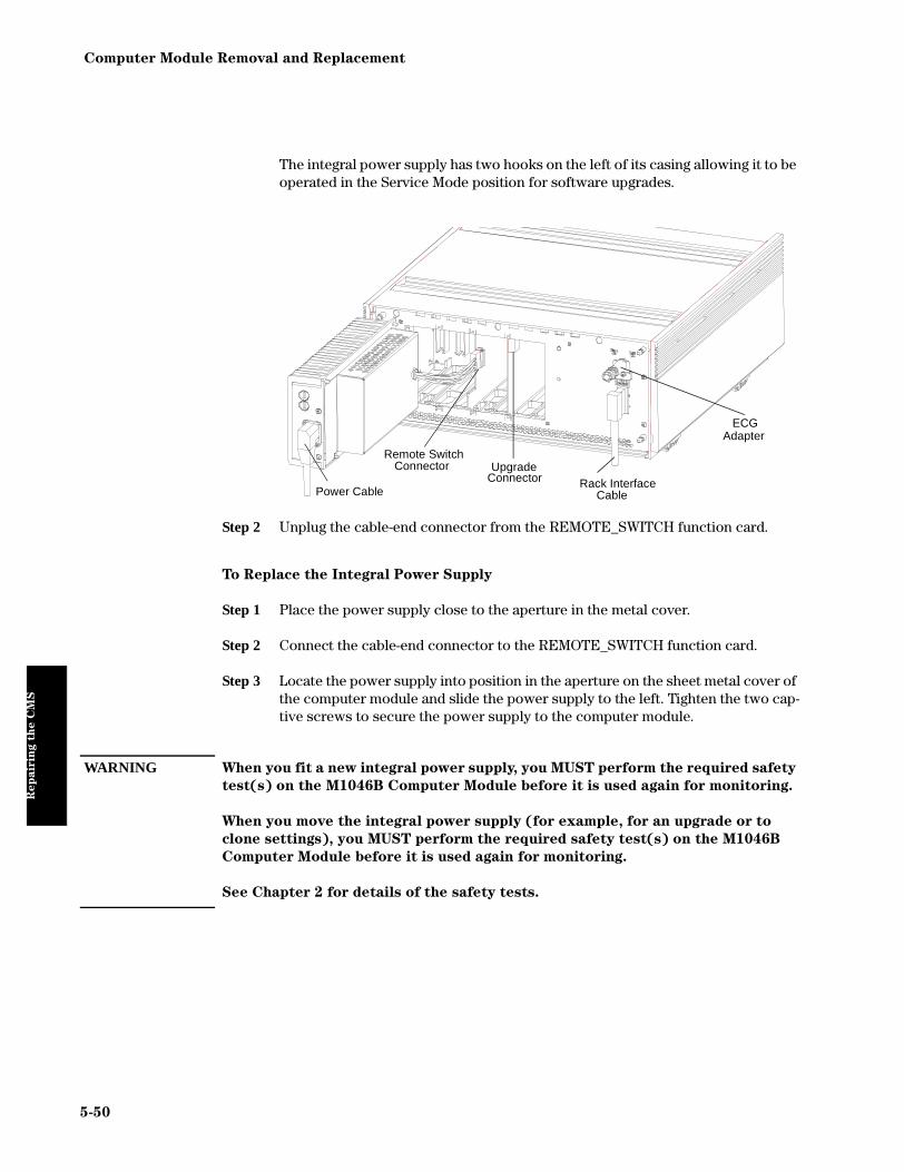
Computer Module Removal and Replacement
Rep
air
ing t
he C
MS
The integral power supply has two hooks on the left of its casing allowing it to be operated in the Service Mode position for software upgrades.
Step 2 Unplug the cable-end connector from the REMOTE_SWITCH function card.
To Replace the Integral Power Supply
Step 1 Place the power supply close to the aperture in the metal cover.
Step 2 Connect the cable-end connector to the REMOTE_SWITCH function card.
Step 3 Locate the power supply into position in the aperture on the sheet metal cover of the computer module and slide the power supply to the left. Tighten the two cap-tive screws to secure the power supply to the computer module.
WARNING When you fit a new integral power supply, you MUST perform the required safety
test(s) on the M1046B Computer Module before it is used again for monitoring.
When you move the integral power supply (for example, for an upgrade or to
clone settings), you MUST perform the required safety test(s) on the M1046B
Computer Module before it is used again for monitoring.
See Chapter 2 for details of the safety tests.
Power Cable
Remote SwitchConnector Upgrade
Connector
ECGAdapter
Rack InterfaceCable
5-50

Computer Module Removal and Replacement
Rep
air
ing t
he C
MS
Sheet Metal Cover - M1046B only
To Remove the Sheet Metal Cover
Step 1 Remove Plastic Cover, power cord, integral power supply and unplug the Satel-lite Rack cable and the ECG Adapter.
Step 2 Use a cross-tipped screwdriver to remove the 4 screws that secure the cover to the computer module and remove the cover.
To Replace the Sheet Metal Cover
Step 1 Locate the cover into position in the front of the computer module. Replace and tighten the 4 screws to secure the sheet metal cover to the computer module.
Step 2 Replace the integral power supply and plug in the power cord, Satellite Rack cable and the ECG Adapter. Replace the Plastic Cover.
WARNING When you replace/refit the integral power supply in the M1046B Computer
Module, a safety test MUST be performed on the Computer Module before it is
used again for monitoring. See Chapter 2 for details of the safety tests.
Front Function Card
The work-flow diagram for removing function cards is as follows. The function card can be removed using a board extractor tool (M1046-44901).The front
function cards
are in even slots
2-24. An
individual face
plate or one sheet
metal cover will
cover the function
cards.
RemoveIntegral
Rack
Remove Sheet Metal Cover
Remove Function
Card
5-51

Computer Module Removal and Replacement
Rep
air
ing t
he C
MS
To Remove a Front Function Card
Step 1 If the computer module has a sheet metal cover over the function cards, use a cross-tipped screwdriver to remove the 4 screws that secure the cover to the computer module and remove the cover.
Step 2 For M1046B onlyLoosen the two screws for the metal function card lock and slide it to the left to allow cards to be removed. If you are removing a function card in front slots 18, 20, 22, or 24, remove the AUX_CONNECTOR card’s jumper card from the RACK_IF connector.
Step 3 Using the board extractor tool attached to the rear of the computer module, firmly grip the card and slide it out horizontally until the card is completely clear of the computer module.
To Replace a Front Function Card
CPC FLASHCARD COVER
INTEGRAL RACK
SHEET METALCOVER
M1046A COMPUTER MODULE with integral rack M1046B COMPUTER MODULE with integral power supply
PLASTIC FRONT COVER
COVERSHEET METAL
FUNCTION CARDLOCKING PLATE
INTEGRAL POWER SUPPLY
LOOSEN SCREWS
AUXCONNECTORJUMPER CARD
SLIDE LEFT
5-52

Computer Module Removal and Replacement
Rep
air
ing t
he C
MS
Step 1 Locate the card-edge into the appropriate slot in the computer module.
Step 2 Slide the card into the computer module until it locates into the connector center plane, then seat the card firmly into the connector.
Step 3 For M1046B onlySlide the metal function card lock to the right so the function cards cannot be removed and tighten the two screws. Replace the AUX_CONNECTOR card’s jumper card to the RACK_IF connector.
Step 4 If the computer module has a sheet metal cover, locate the cover into position in the front of the computer module. Ensure that the CPC Flash port in slot 12 is accessible through the access window in the cover. Replace and tighten the 4 screws to secure the cover to the computer module.
Step 5 For M1046B onlyReplace the ECG_sync adapter so that you can connect to it through the Plastic Cover.
Step 6 If the function card has a face plate, use a cross-tipped screwdriver to tighten the captive screw on the top of the face plate to secure the card to the computer module.
WARNING When you replace/refit the integral power supply in the M1046B Computer
Module, a safety test MUST be performed on the Computer Module before it is
used again for monitoring. See Chapter 2 for details of the safety tests.
5-53

Computer Module Removal and Replacement
Rep
air
ing t
he C
MS
Rear Function Cards
The work-flow diagram for removing function cards is as follows. The function card can be removed using a board extractor tool (M1046-44901).
To Remove a Rear Function Card
Step 1 Using a flat-tipped screwdriver, remove any cables connected to the rear edge of the card.
Step 2 Using a cross-tipped screwdriver, back-out the captive screw on the top of the face plate that secures the card to the computer module.
Step 3 Using the board extractor tool attached to the rear of the computer module, firmly grip the metal plate at the rear of the card and slide it out horizontally until it completely clears the computer module.
To Replace a Function Card with a Face Plate
Step 1 For M1046B onlyIf you are replacing any DSPC controller card with the Asian/Eastern Europe lan-guage option fitted, then you need to set the DIP switches on the function card to select the correct language.
Step 2 Locate the card-edge into the appropriate slot in the computer module.
Rear function
cards are in odd
slots 1-21.
Remove Rear
Cover
Remove any
attachedcables
Remove Function
Card
5-54

Computer Module Removal and Replacement
Rep
air
ing t
he C
MS
Step 3 Slide the card into the computer module until it locates into the connector on the backplane, then seat the card firmly into the center plane.
Step 4 Using a cross-tipped screwdriver, tighten the captive screw on the top of the card to secure the card to the computer module.
Configuring the Display Controller Card
For each type of display there are two types of display controller card: Roman alphabet-based and other languages. For part numbers see the Parts List chapter. The non-Roman-based controller card contains a Font ROM with four switches for selecting the language.
If you are replacing the display controller card with an Eastern Europe or Asian language option fitted, then you need to ensure that the DIP switches are set to the correct language. See the following figure and table for the language settings.
LanguageDIP-Switch Settings
1 2 3 4
Factory Default (Font ROM disabled)
closed closed closed closed
Japanese open open open open
Chinese (PRC) closed open open open
Taiwanese (ROC) open closed open open
EUR-EAST (Polish, Russian, Greek, Turkish)
open open closed open
Factory Default Japanese Chinese (PRC)
Taiwanese (ROC) EUR-EAST (Pol, Rus, Gre, Tur)
5-55

Computer Module Removal and Replacement
Rep
air
ing t
he C
MS
Side Cover
The work-flow diagram for the removal of the side cover is as follows.
To Remove the Side Covers
Step 1 Grip the side cover and slide it horizontally towards the front of the computer module.
Step 2 Lift the cover so the tabs on the bottom of the cover slide out of the slots and clear of the computer module.
To Replace the Side Covers
Step 1 Locate the tabs on the bottom of the side cover into the slots on the side of the computer module and align it vertically to the computer module.
Step 2 Slide the cover horizontally toward the back of the computer module so that the tabs lock the side cover in place.
The side covers
must be removed
to gain access to
the screws
attaching the top
cover to the
computer
modules.
Remove Integral
Rack
Remove Side
Cover
5-56

Computer Module Removal and Replacement
Rep
air
ing t
he C
MS
Top Cover
The work flow diagram for removal of the top cover is as follows.
To Remove the Top Cover
Step 1 Using a cross-tipped screwdriver, remove the 6 screws (3 on each side) that secure the top cover to the computer module.
Step 2 Lift the top cover clear of the computer module.
To Replace the Top Cover
Step 1 Locate the top cover onto the computer module.
Step 2 Using the cross-tipped screwdriver, replace and tighten the 6 screws (three each side).
The top cover
must be removed
to gain access to
the center board
of the computer
module.
Remove all function
cards
Remove DC/DC
Convertor
Remove Side
Cover
Remove Top
Cover
5-57

Computer Module Removal and Replacement
Rep
air
ing t
he C
MS
Backplane Board Assy
The work flow diagram for removal the backplane is as follows
To Remove the Backplane Board Assy
Step 1 Grip the uppermost edge of the backplane and lift it directly out of the computer module.
To Replace the Backplane Board Assy
Step 1 Stand to the rear of the computer module and hold the backplane by its upper-most edge with the large space between the connectors on the left.
Step 2 Locate and seat the backplane in the slot in the center of the computer module.
The backplane
holds the
connectors for the
front and rear
function cards.
Remove DC/DC
Convertor
Remove Side and
Top Cover
Remove Backplane
Remove all function
cards
5-58

Computer Module Removal and Replacement
Rep
air
ing t
he C
MS
Plastic Feet
To Remove the Plastic Feet
Step 1 Place the computer module upside-down on a suitable plain table.
Step 2 Using a cross-tipped screwdriver, remove the screw securing each of the plastic feet.
To Replace the Plastic Feet
Step 1 Locate the 4 feet over the 4 holes on the base of the computer module so that the slot it forms with the base faces the rear of the computer module.
Step 2 Replace and tighten the screws to secure the feet in place.
CAUTION M1046B Computer Module only:
When you remove the plastic feet you may find there are standoffs to increase
the height under the computer module. You must refit these standoffs with the
plastic feet or use shorter screws to refit the feet alone.
The plastic feet
are removed for
various
mounting
solutions.
5-59
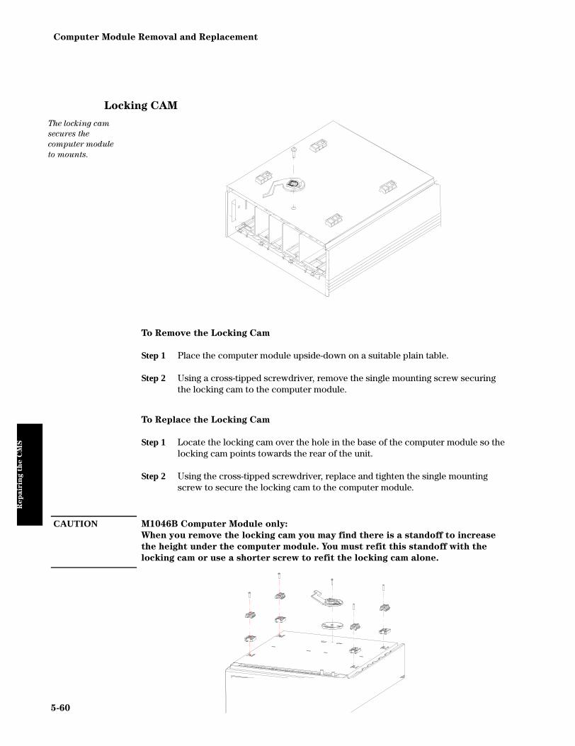
Computer Module Removal and Replacement
Rep
air
ing t
he C
MS
Locking CAM
To Remove the Locking Cam
Step 1 Place the computer module upside-down on a suitable plain table.
Step 2 Using a cross-tipped screwdriver, remove the single mounting screw securing the locking cam to the computer module.
To Replace the Locking Cam
Step 1 Locate the locking cam over the hole in the base of the computer module so the locking cam points towards the rear of the unit.
Step 2 Using the cross-tipped screwdriver, replace and tighten the single mounting screw to secure the locking cam to the computer module.
CAUTION M1046B Computer Module only:
When you remove the locking cam you may find there is a standoff to increase
the height under the computer module. You must refit this standoff with the
locking cam or use a shorter screw to refit the locking cam alone.
The locking cam
secures the
computer module
to mounts.
5-60

Module Rack
Rep
air
ing t
he C
MS
Module Rack
The following is a list of replaceable parts for the module rack.
Plug-In Module
To Remove the Plug-in Module from the Rack
Step 1 Grip the plug-in module and lift the snaplock at the bottom of the module. Then pull the module directly out of the rack.
To Replace the Plug-in Module in the Rack
Step 1 Locate the plug-in module into a vacant slot in the rack. Push the plug-in module into the integral rack slot until the module locks into place.
Replaceable Part Page
Plug-In Module 5-61
Mounting Clamp 5-62
The plug-in
modules can be
used in integral
racks and
Satellite Racks.
wmer16.mif
5-61

Module Rack
Rep
air
ing t
he C
MS
Mounting Clamp
To Remove the Mounting Clamp
Step 1 Remove the Satellite Rack from the rail or pole by loosening the clamp.
Step 2 Using a cross-tipped screwdriver, remove the two screws securing the clamp to the rack.
To Replace the Mounting Clamp
Step 1 Align the holes in the mounting clamp with one pair of holes on the back of the Satellite Rack, depending on whether it is to be mounted on a horizontal rail or vertical pole.
Step 2 Using a cross-tipped screwdriver, replace and tighten the screws.
Step 3 Attach the mounting clamp and Satellite Rack to either the rail or the pole.
5-62

Plug-in Modules
Rep
air
ing t
he C
MS
Plug-in Modules
The following is a list of replaceable parts for the plug-in modules.
Replaceable Parts Page
Snap Lock 5-64
Plug-In Module Disassembly 5-65
NBP Inlet Connector Insert 5-67
NBP Pump 5-68
tcpO2/tcpCO2 Calibration Chamber Kit 5-69
Recorder Module Paper 5-71
5-63

Plug-in Modules
Rep
air
ing t
he C
MS
Snap Lock
To Remove the Snap Lock
Step 1 Grip the module firmly in one hand and using your thumb, pull the front edge of the snap lock away from the plug-in module so that the lug on the snap lock clears the retaining edge of the module.
Step 2 Push on the rear edge of the snap lock to move the snap lock through the slot toward the front of the module until it is clear.
To Replace the Snap lock
Step 1 Locate the snap lock into the slot on the bottom of the module.
Step 2 Slide the snap lock toward the rear of the module until the lock snaps into posi-tion.
The snap lock
holds the plug-in
module in the
integral or
Satellite Rack.
rsnaplck.mif
`
rsnapcth.mif
5-64

Plug-in Modules
Rep
air
ing t
he C
MS
Plug-In Module Disassembly
The work-flow for plug-in module disassembly is as follows.
WARNING When you disassemble/assemble a plug-in module a patient leakage current test
must be performed before it is used again for monitoring. See Chapter 2 for
details.
Disassembly of
the parameter
module enables
replacement of
the front
assembly,
overlay, middle
frame, LEDs,
switches and
connectors.
Remove Front
Housing
Remove Module Housing
Remove Frame
Replace Parts
PRESS
PRESS
PRESSPRESS
PRESS
Remove Module Housing
Remove Frame
1 2
3
Front Housing
Module HousingRemove Front Housing
Replace Parts4
Frame
5-65

Plug-in Modules
Rep
air
ing t
he C
MS
To Disassemble a Plug-In Module
Step 1 Remove the Front Housing.
• Place the module on a flat surface and insert a card (similar to a credit or cheque type card) into one side of the module to disengage the 2 tabs securing the front housing to the module housing.
• Pull the edge of the front housing away from the module housing.
• Carefully turn the module over so the free edge does not reengage and repeat the first two steps on the other side of the module. The front housing should now be free of the module housing.
Step 2 Press the 4 tabs on the front rim of the module housing and remove the module housing from the internal frame and PCB.
Step 3 Press the 2 tabs on the top and 2 tabs on the bottom of the frame and pull the frame clear of the PCB.
Step 4 Replace the appropriate connector, switches and LEDs on the module.
To Reassemble a Plug-in Module
Step 1 Seat the connectors and PCBs into position in the frame.
Step 2 Carefully snap-lock the frame together with the module PCB inside.
Step 3 Re-insert and snap-fit the frame into the module case so the front and rear con-nectors align with the module case.
Step 4 Snap-fit the front housing onto the front of the module case so the openings in the front housing match the LEDs and keys.
5-66

Plug-in Modules
Rep
air
ing t
he C
MS
NBP Inlet Connector Insert
To Remove the NBP Inlet Connector Insert
Step 1 Use a 6-mm Allen key to unscrew the defective connector insert from the inlet of the NBP module.
Step 2 Verify that the connector insert contains 4 metal balls in the transparent cover. If a ball is missing, it may have fallen into the module tubing. Damage could result necessitating exchange of the module.
To Replace the NBP Connector Insert
Step 1 Using a torque wrench, screw the replacement connector insert into the NBP module, applying a torque of 10 Ncm (14 oz inches).
Step 2 Perform the NBP module specification test as described in this manual.
The NBP Inlet
Connector is
replaced without
opening the
module. Do not
remove the
transparent cover
on the connector.
oplevel.mif
5-67

Plug-in Modules
Rep
air
ing t
he C
MS
NBP Pump
To Remove the NBP Pump
Step 1 Using a small screwdriver or similar tool, unplug the white 4-pin connector from the socket through the access hole on the top rear module casing.
Step 2 Grip and pull the red pump block assembly from the air inlet connector and the module assembly.
To Replace the NBP Pump
Step 1 Remove the protective cap from the air inlet connector on the pump module.
Step 2 Facing the front of the module, locate the pump assembly into the left side of the module assembly. Ensure the air inlet tube fits properly into the air inlet connec-tor of the pump.
Step 3 Using a small screwdriver or similar tool, plug the white 4-pin connector into the socket on the module assembly. To gain access to the connector, carefully lift the PCB on the opposing side of the module assembly.
Step 4 Once the pump is in place, locate the PCB into its original position and reassem-ble the module. Perform the NBP module specification test in this manual. Cali-bration is required if the test fails.
The NBP pump
inflates the
pressure cuff
Disassemble the module down to the
frame
Remove the Pump
Replace Parts
1
2
5-68

Plug-in Modules
Rep
air
ing t
he C
MS
tcpO2/tcpCO2 Calibration Chamber Kit
To Remove the Calibration Chamber
Step 1 Using a flat-tipped screwdriver, remove the screw holding the calibration cham-ber in place on the front of the plug-in module.
Step 2 Lift the chamber off the plug-in module. Ensure that the white plastic switch tip located in the module is not lost.
To Replace the Calibration Chamber
Step 1 Ensure the white plastic switch tip is in place in the plug-in module.
Step 2 Place the calibration chamber in the allocated position on the plug-in module.
Step 3 Insert and tighten the screw into the calibration chamber, securing it to the plug-in module.
O2/CO2 CAL
tcpO /tcpCOM1018A
T
80x1002 2
CALIBRATIONCHAMBER
5-69

Plug-in Modules
Rep
air
ing t
he C
MS
FIO2 Battery Replacement
To Replace the FIO2 Battery
Step 1 Remove the printed circuit boards from the frame by releasing the two catches.
Step 2 Unsolder the battery.
Step 3 Discard the battery according to local regulations.
Step 4 Solder the new battery into place.
Step 5 Reassemble the module, being careful to snap-lock all catches back into place.
Step 6 Perform 21% and 100% calibration, as described in the User’s Reference Manual.
Step 7 Leave the module in a powered-on CMS for 20 hours to charge battery.
Disassemble module down to the printed circuit board
Remove andreplace battery
Calibrate module
Charge for 20 hours in
powered-on CMS
5-70

Plug-in Modules
Rep
air
ing t
he C
MS
Recorder Module Paper
The recorder will not run when the door is open or when the recorder is out of paper. To prevent damage to the recorder module, use only Philips approved paper (Philips re-order number 40477A/B)
To Load Paper into the Recorder Module
Step 1 Remove the empty core from the previous roll of paper.
Step 2 Cut off and discard the first few inches of paper to eliminate any traces of adhe-sive.
Step 3 Pull out several inches of paper from the new roll, holding the roll with the loose end hanging over the top toward you.
Step 4 Open the door and push the paper roll into the holders in the recorder.
Step 5 Thread the paper under the roller and over the plastic shelf far enough so it goes around the roller and comes out above it.
Step 6 Drape the paper over the end of the door and close the door. The paper should be visible and draped down in front of the door.
5STEP
PLASTIC SHELF
PAPER ROLLER
3STEP
6STEP
5-71

Plug-in Modules
Rep
air
ing t
he C
MS
5-72

Chapter 6 Parts List for CMS
Parts L
ist
for C
MS
This chapter provides the replacement and exchange part numbers (if available) for the Philips CMS Patient Monitoring System. Exploded views of the Computer Module and Display Module are provided to assist in identifying certain parts.
Objective
To provide you with a list of available parts for the CMS.
Concepts
The circuit boards used in the monitor contain Surface Mounted Devices (SMD) which can only be repaired with special equipment, not available in the field. For this reason, the majority of the parts used in the system can only be replaced at board level.
Parts List for CMS 6-1
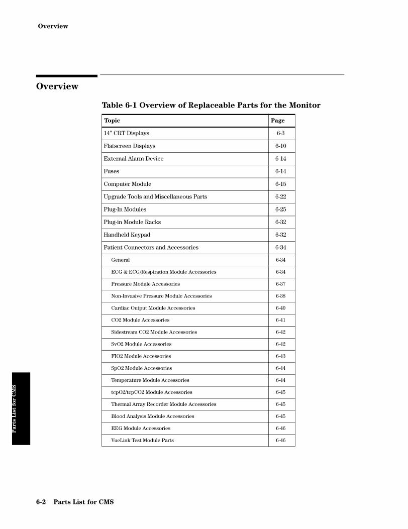
Overview
Parts L
ist
for C
MS
Overview
Table 6-1 Overview of Replaceable Parts for the Monitor
Topic Page
14” CRT Displays 6-3
Flatscreen Displays 6-10
External Alarm Device 6-14
Fuses 6-14
Computer Module 6-15
Upgrade Tools and Miscellaneous Parts 6-22
Plug-In Modules 6-25
Plug-in Module Racks 6-32
Handheld Keypad 6-32
Patient Connectors and Accessories 6-34
General 6-34
ECG & ECG/Respiration Module Accessories 6-34
Pressure Module Accessories 6-37
Non-Invasive Pressure Module Accessories 6-38
Cardiac Output Module Accessories 6-40
CO2 Module Accessories 6-41
Sidestream CO2 Module Accessories 6-42
SvO2 Module Accessories 6-42
FIO2 Module Accessories 6-43
SpO2 Module Accessories 6-44
Temperature Module Accessories 6-44
tcpO2/tcpCO2 Module Accessories 6-45
Thermal Array Recorder Module Accessories 6-45
Blood Analysis Module Accessories 6-45
EEG Module Accessories 6-46
VueLink Test Module Parts 6-46
6-2 Parts List for CMS

14” CRT Displays
Parts L
ist
for C
MS
14” CRT Displays
The color-dependent parts that can can be replaced on the 14” CRT Displays are listed in the following table:
NOTE Along with all Membrane Switches always order a Retaining Clip (p/n 0510-1637)
Table 6-2 CRT Display - Color-dependent Replaceable Parts
Old (Darker) Color New (Lighter) Color
Description (see exploded views) Exchange
Part
Number
New
Part Number
Exchange
Part
Number
New
Part Number
M1094-68002 M1094-60002 M1094-68004 M1094-60004 M1094B MONITOR 14” COLOR
M1092-68001 M1092-60001 M1092-68004 M1092-60004 M1092A MONITOR 14” MONO
M1105-60501 M1105-60511 FRONT ASSY DISP M1094A/M1094B 2
M1104-60501 M1104-60511 FRONT ASSY DISP M1092A 2
M1104-61760 STANDARD MEMBRANE SWITCH POLISH
4
M1104-61758 STANDARD MEMBRANE SWITCH CZECH
4
M1104-61757 STANDARD MEMBRANE SWITCH RUSSIAN
4
M1104-61755 STANDARD MEMBRANE SWITCH GREEK
4
M1104-61953 M1104-61753 STANDARD MEMBRANE SWITCH SIMPLIFIED CHINESE
4
M1104-61952 M1104-61752 STANDARD MEMBRANE SWITCH TRADITIONAL CHINESE
4
M1104-61951 M1104-61751 STANDARD MEMBRANE SWITCH KANJI, JAPANESE
4
M1104-61950 M1104-61750 STANDARD MEMBRANE SWITCH DANISH
4
M1104-61949 M1104-61749 STANDARD MEMBRANE SWITCH NORWEGIAN
4
M1104-61948 M1104-61748 STANDARD MEMBRANE SWITCH FINNISH
4
M1104-61947 M1104-61747 STANDARD MEMBRANE SWITCH SWEDISH
4
M1104-61946 M1104-61746 STANDARD MEMBRANE SWITCH ITALIAN
4
M1104-61945 M1104-61745 STANDARD MEMBRANE SWITCH SPANISH
4
M1104-61944 M1104-61744 STANDARD MEMBRANE SWITCH DUTCH
4
M1104-61943 M1104-61743 STANDARD MEMBRANE SWITCH GERMAN
4
Parts List for CMS 6-3

14” CRT Displays
Parts L
ist
for C
MS
M1104-61942 M1104-61742 STANDARD MEMBRANE SWITCH FRENCH
4
M1104-61941 M1104-61741 STANDARD MEMBRANE SWITCH ENGLISH
4
M1104-61933 CLASSIC MEMBRANE SWITCH SIMPLIFIED CHINESE
4
M1104-61932 CLASSIC MEMBRANE SWITCH TRADITIONAL CHINESE
4
M1104-61931 CLASSIC MEMBRANE SWITCH KANJI, JAPANESE
4
M1104-61930 CLASSIC MEMBRANE SWITCH DANISH
4
M1104-61929 CLASSIC MEMBRANE SWITCH NORWEGIAN
4
M1104-61928 CLASSIC MEMBRANE SWITCH FINNISH
4
M1104-61927 CLASSIC MEMBRANE SWITCH SWEDISH
4
M1104-61926 CLASSIC MEMBRANE SWITCH ITALIAN
4
M1104-61925 CLASSIC MEMBRANE SWITCH SPANISH
4
M1104-61924 CLASSIC MEMBRANE SWITCH DUTCH
4
M1104-61923 CLASSIC MEMBRANE SWITCH GERMAN
4
M1104-61922 CLASSIC MEMBRANE SWITCH FRENCH
4
M1104-61921 CLASSIC MEMBRANE SWITCH ENGLISH
4
M1104-61911 CLASSIC MEMBRANE SWITCH KANJI, JAPANESE (w/o SUSPEND KEY)
4
M1104-61907 CLASSIC MEMBRANE SWITCH SWEDISH (w/o SUSPEND KEY)
4
M1104-61906 CLASSIC MEMBRANE SWITCH ITALIAN (w/o SUSPEND KEY)
4
M1104-61905 CLASSIC MEMBRANE SWITCH SPANISH (w/o SUSPEND KEY)
4
M1104-61904 CLASSIC MEMBRANE SWITCH DUTCH (w/o SUSPEND KEY)
4
M1104-61903 CLASSIC MEMBRANE SWITCH GERMAN (w/o SUSPEND KEY)
4
M1104-61902 CLASSIC MEMBRANE SWITCH FRENCH (w/o SUSPEND KEY)
4
M1104-61901 CLASSIC MEMBRANE SWITCH ENGLISH (w/o SUSPEND KEY)
4
Table 6-2 CRT Display - Color-dependent Replaceable Parts
Old (Darker) Color New (Lighter) Color
Description (see exploded views) Exchange
Part
Number
New
Part Number
Exchange
Part
Number
New
Part Number
6-4 Parts List for CMS

14” CRT Displays
Parts L
ist
for C
MS
089094877MOL STANDARD BEZEL OVERLAY ENGLISH
089094878MOL STANDARD BEZEL OVERLAY FRENCH
089094879MOL STANDARD BEZEL OVERLAY GERMAN
089094880MOL STANDARD BEZEL OVERLAY DUTCH
089094881MOL STANDARD BEZEL OVERLAY SPANISH
089094882MOL STANDARD BEZEL OVERLAY ITALIAN
089094883MOL STANDARD BEZEL OVERLAY TRADITIONAL CHINESE
089094884MOL STANDARD BEZEL OVERLAY SWEDISH
089094885MOL STANDARD BEZEL OVERLAY FINNISH
089094886MOL STANDARD BEZEL OVERLAY NORWEGIAN
089094887MOL STANDARD BEZEL OVERLAY SIMPLIFIED CHINESE
089094888MOL STANDARD BEZEL OVERLAY DANISH
089094889MOL STANDARD BEZEL OVERLAY KANJI, JAPANESE
089095185MOL STANDARD BEZEL OVERLAY PORTUGUESE
089095476MOL STANDARD BEZEL OVERLAY GREEK
089095475MOL STANDARD BEZEL OVERLAY RUSSIAN
089095474MOL STANDARD BEZEL OVERLAY POLISH
89092814MOL CLASSIC BEZEL OVERLAY ENGLISH
89092993MOL CLASSIC BEZEL OVERLAY FRENCH
89092994MOL CLASSIC BEZEL OVERLAY GERMAN
89092995MOL CLASSIC BEZEL OVERLAY DUTCH
89092996MOL CLASSIC BEZEL OVERLAY SPANISH
89092997MOL CLASSIC BEZEL OVERLAY ITALIAN
89092998MOL CLASSIC BEZEL OVERLAY SWEDISH
89092999MOL CLASSIC BEZEL OVERLAY FINNISH
89093171MOL CLASSIC BEZEL OVERLAY NORWEGIAN
89093173MOL CLASSIC BEZEL OVERLAY JAPANESE
89093174MOL CLASSIC BEZEL OVERLAY TRADITIONAL CHINESE
89093175MOL CLASSIC BEZEL OVERLAY SIMPLIFIED CHINESE
Table 6-2 CRT Display - Color-dependent Replaceable Parts
Old (Darker) Color New (Lighter) Color
Description (see exploded views) Exchange
Part
Number
New
Part Number
Exchange
Part
Number
New
Part Number
Parts List for CMS 6-5

14” CRT Displays
Parts L
ist
for C
MS
89093870MOL CLASSIC BEZEL OVERLAY ENGLISH (w/o SUSPEND KEY)
89093871MOL CLASSIC BEZEL OVERLAY FRENCH (w/o SUSPEND KEY)
89093872MOL CLASSIC BEZEL OVERLAY GERMAN (w/o SUSPEND KEY)
89093873MOL CLASSIC BEZEL OVERLAY DUTCH (w/o SUSPEND KEY)
89093874MOL CLASSIC BEZEL OVERLAY SPANISH (w/o SUSPEND KEY)
89093875MOL CLASSIC BEZEL OVERLAY ITALIAN (w/o SUSPEND KEY)
89093876MOL CLASSIC BEZEL OVERLAY SWEDISH (w/o SUSPEND KEY)
89093877MOL CLASSIC BEZEL OVERLAY JAPANESE (w/o SUSPEND KEY)
M1104-47402 M1104-47412 ROTARY KNOB HIF (THUMBWHEEL)
M1104-47401 M1104-47411 KNOB POWER 5
M1104-44101 M1104-44111 COVER CONNECTOR 6
M1104-44102 CLEAR PLASTIC SHIELD
M1104-00201 M1104-00301 PANEL BLANK 4
311920406672FMI 311920407511FMI REAR ENCLOSURE M1094B/M1094A/M1092A DISPLAY
15
311920808962FMI 31192013074FMI REAR COVER 14
Table 6-2 CRT Display - Color-dependent Replaceable Parts
Old (Darker) Color New (Lighter) Color
Description (see exploded views) Exchange
Part
Number
New
Part Number
Exchange
Part
Number
New
Part Number
6-6 Parts List for CMS

14” CRT Displays
Parts L
ist
for C
MS
The color-independent parts that can be replaced on the 14” CRT Displays are listed in this table:
Table 6-3 CRT Display Module - Color-independent Replaceable Parts
Exchange
Part
Number
New
Part Number Description (see exploded views)
311920809500FMI M1094A SMPS 1
991920860092FMI M1094A CRT BOARD ASSY
311920809471FMI M1094A DEFLECTION ASSY (For S/N > 3014I07762)
M1094-74001 M1094A DEFLECTION ASSY & CRT Board (For S/N < 3014I07762)
M1094-60111 AC DELAY LINE RELAY FOR 220-240V
311920809490FMI M1094A INTERFACE ASSY
991920863401FMI M1094B SMPS 1
991920863381FMI M1094B VIDEO ASSY
991920863391FMI M1094B DEFLECTION ASSY
M1092-68501 311920809530FMI M1092A SMPS 1
991920857901FMI M1092A DEFLECTION & VIDEO ASSY
M1105-88400 LOCKING CLIP
M1105-88410 CLIP, COMPONENT MONITORING SYSTEM BEZEL, PK=100
M1104-61602 CABLE ASSEMBLY (without TONE MODULATION)
M1104-85051 HIF CPU F/W (without TONE MODULATION)
1820-7777 HIF CPU F/W (inc. TONE MODULATION)
M1104-66505 BOARD ASSY HIF 3
M1104-44102 CLEAR PLASTIC SHIELD
5041-4264 FOOT 7
5041-4265 CAM, LOCKING 8
2110-0365 FUSE T4A M1092A/M1094A/B (UL, 110V POWER SUPPLY) 9
242208625096FMI FUSE T2A M1092A (VDE, 220V POWER SUPPLY) 9
242208601266FMI FUSE T2A M1092A (UL, 220V POWER SUPPLY) 9
242208610219FMI FUSE T2.5A M1094A (VDE, 220V POWER SUPPLY) 9
242208610009FMI FUSE T2.5A M1094A (UL, 220V POWER SUPPLY) 9
242208610239FMI FUSE T3.15A M1094B (VDE or UL, 220V POWER SUPPLY) 9
2110-1025 Fuse T3.15A M1046B Power Supply
2110-0567 FUSE HOLDER (220V) & M1046B Power Supply
2110-0565 FUSE HOLDER (110V)
1990-1259 POWER LED (on HIF)
0510-1637 RETAINING CLIP (Bezel)
311920809661FMI POWER SWITCH ASSY M1094A (for S/N > 2950I07333) 10
311920809660FMI POWER SWITCH ASSY M1094A (for S/N < 2950I07333) 10
311920851940FMI LINE FILTER ASSY M1094A 11
311920809640FMI FUSE ASSEMBLY M1094A 12
311920809633FMI POWER SWITCH ASSY M1092A (for S/N > 2950I07633) 10
311920809630FMI POWER SWITCH ASSY M1092A (for S/N < 2950I07633) 10
311920880721FMI POWER SWITCH ASSY M1094B
311920809620FMI VIDEO/Philips-HIL CONNECTOR PCA 13
240325723322FMI LOUDSPEAKER
991920712201FMI M1094B REAR COVER SERVICE KIT
Parts List for CMS 6-7

14” CRT Displays
Parts L
ist
for C
MS
Figure 6-1 Display Module Exploded View M1094B195 x 150
REAR ENCLOSURE(31192040667FMI)
15
FUSES (see listing) 9
REAR COVER 311920808962FMI
14
FOOT 5041-4264
LOCKING CAM 5041-4265 M1094B SMPS
991920863401FMI
18
7
disex1.mif
6-8 Parts List for CMS

14” CRT Displays
Parts L
ist
for C
MS
Figure 6-2 Display Module Exploded View M1092A/M1094A
4MEMBRANE SWITCH
OR BLANK PANEL (SEE LISTING)
14REAR ENCLOSURE M1092A/
M1094A DISPLAYS (31192042435FMI)
6COVER CONNECTOR
(M1104-44101)
12FUSE ASSEMBLY M1094A
(311920809640FMI)
10POWER SWITCH ASSEMBLY
(see listing)
11LINE FILTER ASSY M1094A
(311920809640FMI)
2
3BOARD ASSY HIF
(M1104-66505)
8CAM, LOCKING
(5041-4265)
7FOOT
(5041-4264)
1M1094A SMPS (311920809500FMI)M1092A SMPS (311920809471FMI)
2FRONT ASSY DISP M1094A/M1094B (M1105-60501)FRONT ASSY DISP M1092A (M1104-60501)
13
VIDEO/Philips-HIL CONNECTORPCA
15REAR ENCLOSURE M1092A/M1094A DISPLAYS
(31192042435FMI)
9FUSES
(see listing)
5KNOB POWER (M1104-47401)
Parts List for CMS 6-9

Flatscreen Displays
Parts L
ist
for C
MS
Flatscreen Displays
The parts that can be replaced on Old Color M1095A Flatscreen Displays are listed in this table.
Table 6-4 Old Color M1095A Flatscreen Display - Replaceable Parts
Exchange
Part Number
New
Part Number
Description
M1095-68001 M1095-60001 Flatscreen Assembly (English)
M1095-68002 M1095-60002 Flatscreen Assembly (French)
M1095-68003 M1095-60003 Flatscreen Assembly (German)
M1095-68004 M1095-60004 Flatscreen Assembly (Dutch)
M1095-68005 M1095-60005 Flatscreen Assembly (Spanish)
M1095-68006 M1095-60006 Flatscreen Assembly (Italian)
M1095-68007 M1095-60007 Flatscreen Assembly (Swedish)
M1095-68008 M1095-60008 Flatscreen Assembly (Finnish)
M1095-68009 M1095-60009 Flatscreen Assembly (Norwegian)
M1095-68010 M1095-60010 Flatscreen Assembly (Danish)
M1095-68011 M1095-60011 Flatscreen Assembly (Kanji, Japanese)
M1095-68012 M1095-60012 Flatscreen Assembly (Trad. Chinese)
M1095-68013 M1095-60013 Flatscreen Assembly (Sim. Chinese)
M1095-68014 M1095-60014 Flatscreen Assembly (Portuguese)
M1095-68000 M1095-60000 Flatscreen Assembly (Blank)
M1095-68501 M1095-66501 Video Board
M1095-61941 Keypad (English)
M1095-61942 Keypad (French)
M1095-61943 Keypad (German)
M1095-61944 Keypad (Dutch)
M1095-61945 Keypad (Spanish)
M1095-61946 Keypad (Italian)
M1095-61947 Keypad (Swedish)
M1095-61948 Keypad (Finnish)
M1095-61949 Keypad (Norwegian)
M1095-61950 Keypad (Danish)
M1095-61951 Keypad (Kanji, Japanese)
M1095-61952 Keypad (Trad. Chinese)
M1095-61953 Keypad (Sim. Chinese)
M1095-61954 Keypad (Portuguese)
0510-1637 Push-on clips for keypad
M1095-65201 Housing kit (front, back and lightpipe)
6-10 Parts List for CMS

Flatscreen Displays
Parts L
ist
for C
MS
The parts that can be replaced on M1095A Flatscreen Displays with the new lighter color exterior plastic parts, identified with the CMS logo on the bezel, are listed in this table:
M1095-68300 Loudspeaker (including cable)
M1104-66551 HIF Board
2090-0546 Backlight (for Preventive Maintenance)Note: only for M1095A serial numbers with prefix less
than 3805G.
M1095-44101 Plastic cover for HIL input
M1104-47402 Brightness control (thumbwheel)
M1095-02303 Cable holder video cable
M1095-04602 Anti-glare screen
0590-0199 2 x Nuts for video cable
Table 6-5 CMS New Color M1095A Flatscreen - Replaceable Parts
Exchange
Part
Number
New
Part
Number
Description
M1095-68101 M1095-60101 Flatscreen Assembly (English)
M1095-68102 M1095-60102 Flatscreen Assembly (French)
M1095-68103 M1095-60103 Flatscreen Assembly (German)
M1095-68104 M1095-60104 Flatscreen Assembly (Dutch)
M1095-68105 M1095-60105 Flatscreen Assembly (Spanish)
M1095-68106 M1095-60106 Flatscreen Assembly (Italian)
M1095-68107 M1095-60107 Flatscreen Assembly (Swedish)
M1095-68108 M1095-60108 Flatscreen Assembly (Finnish)
M1095-68109 M1095-60109 Flatscreen Assembly (Norwegian)
M1095-68110 M1095-60110 Flatscreen Assembly (Danish)
M1095-68111 M1095-60111 Flatscreen Assembly (Kanji, Japanese)
M1095-68112 M1095-60112 Flatscreen Assembly (Trad. Chinese)
M1095-68113 M1095-60113 Flatscreen Assembly (Sim. Chinese)
M1095-68114 M1095-60114 Flatscreen Assembly (Portuguese)
M1095-68115 M1095-60115 Flatscreen Assembly (Greek)
M1095-68117 M1095-60117 Flatscreen Assembly (Russian)
M1095-68120 M1095-60120 Flatscreen Assembly (Polish)
Table 6-4 Old Color M1095A Flatscreen Display - Replaceable Parts
Exchange
Part Number
New
Part Number
Description
Parts List for CMS 6-11

Flatscreen Displays
Parts L
ist
for C
MS
M1095-68100 M1095-60100 Flatscreen Assembly (Blank)
M1095-61741 Keypad (English)
M1095-61742 Keypad (French)
M1095-61743 Keypad (German)
M1095-61744 Keypad (Dutch)
M1095-61745 Keypad (Spanish)
M1095-61746 Keypad (Italian)
M1095-61747 Keypad (Swedish)
M1095-61748 Keypad (Finnish)
M1095-61749 Keypad (Norwegian)
M1095-61750 Keypad (Danish)
M1095-61751 Keypad (Kanji, Japanese)
M1095-61752 Keypad (Trad. Chinese)
M1095-61753 Keypad (Sim. Chinese)
M1095-61754 Keypad (Portuguese)
M1095-61755 Keypad (Greek)
M1095-61757 Keypad (Russian)
M1095-61760 Keypad (Polish)
M1095-61758 Keypad (Czech)
M1095-65211 Housing kit (front, back and lightpipe)
M1095-44111 Plastic cover for HIL input
2090-0360 Backlight (for Preventive Maintenance)Note: only for M1095A serial numbers with prefix
equal to 3805G.
2090-0381 Backlight (for Preventive Maintenance)Note: only for M1095A serial numbers with prefix
greater than or equal to 3923G.
M1095-04602 Anti-glare screen
0590-0199 2 x Nuts for video cable
Table 6-5 CMS New Color M1095A Flatscreen - Replaceable Parts
Exchange
Part
Number
New
Part
Number
Description
6-12 Parts List for CMS

Flatscreen Displays
Parts L
ist
for C
MS
The parts that can be replaced on the M1097A Flatscreen Displays are:
The parts that can be replaced on the Remote Power Supply are:
Table 6-6 CMS M1097 XGA Flatscreen Display (15”)- Replaceable Parts
Part Number Description
M1097-68001 15” Flatscreen Display Non-Touch version
M1097-68002 15” Flatscreen Display Touch capable version
M1097-60005 15” Flatscreen Display AC/DC adapter
Table 6-7 Remote Power Supply (M1047A) - Replaceable Parts
Part Number Description
242208601263FMI Fuse (4 A for 11 0V)
242208610239FMI Fuse (3.15 V for 220/240 V)
2110-0565 Fuse holder (110 V)
2110-0567 Fuse holder (220 V) & M1046B
991920864111FMI Remote control board
1990-1259 Power LED
311920880721FMI Power switch assy
311920130301FMI Rear cover
5041-4264 Feet
5041-4265 Cam lock
Table 6-8 Miscellaneous - Replaceable Parts
Part Number Description
M1046-60060 Trackball (wireless)
M1046-60070 Trackball
M1181-61659 Power Supply Remote On/Off cable (kit)
M1181-61655 Video/DC cable (3m)
M1181-61656 Video/DC cable (10m)
M1095-65121 Tilt & swivel mount (supplied with C-Clamp)
M1180-60031 Fixed mount (supplied with C-Clamp)
M1180-60146 Flexible Mount (For Ohmeda equipment with dovetail connection
M1180-60147 Swing Arm Mount (For Ohmeda equipment with dovetail connection)
M1041-23201 C-Clamp
Parts List for CMS 6-13

External Alarm Device
Parts L
ist
for C
MS
External Alarm Device
The External Alarm Device (only with Option H03/4 – the XGA-compatible display configuration) has the following replaceable parts:
Fuses
Table 6-9 External Alarm Device (M1109A) - Replaceable Parts
New part number Description
M1104-64100 Housing Assembly
M1106-00210 Handheld Keypad Bracket
M1104-66551 HIF Board (including ribbon cable)
M1104-66511 LED Carrier Board
M1095-68300 Loudspeaker
M1104-64110 Protection Flap for HIL Connectors
M1181-61659 Remote On/Off Cable
Table 6-10 CMS Fuses
CRT Display Type / Power Supply Type
Line Voltage
100-120 V
Line Voltage
200-240 V
Fuse RatingPart
NumberFuse Rating
Part Number
VDE UL
M1092A Mono CRT Display (Main / Slave) 2 x T4.0 A 2110-0365 2 x T2.0 A 242208625096FMI
242208601266FMI
M1094A Color CRT Display (Main / Slave) 2 x T4.0 A 2110-0365 2 x T2.5 A 242208610219FMI
242208610009FMI
M1094B Color CRT Display (Main / Slave) 2 x T4.0 A 2110-0365 2 x T3.15 A H 242208610239FMI
M1047A Remote Power Supply 2 x T4.0 A 2110-0365 2 x T3.15 A H 242208610239FMI
M1046B Integral Power Supply 2 x T3.15 A H 2110-1025 2 x T3.15 A H 242208610239FMI
6-14 Parts List for CMS

Computer Module
Parts L
ist
for C
MS
Computer Module
The parts that can be replaced on either computer module are found in Table 6-11 Computer Module M1046A - Replaceable Parts. Parts exclusively for the existing computer module are marked M1046A only. Parts exclusively for the new computer module M1046B are found in Table 6-12 Computer Module M1046B - Replaceable Parts.
Table 6-11 Computer Module M1046A - Replaceable Parts
Exchange
Part Number
New
Part Number
Description
M1127-68LLR M1127-66LLR EPROM ASSY #2
M1126-68LLR M1126-66LLR EPROM ASSY #1
LL: Language
13 = SIMPLIFIED CHINESE
12 = TRADITIONAL CHINESE
11 = DANISH (Rel. C only)
10 = JAPANESE, KANJI
09 = FINNISH (Rel. C only)
08 = SWEDISH
07 = NORWEGIAN (Rel. C only)
06 = ITALIAN
05 = SPANISH
04 = DUTCH
03 = GERMAN
02 = FRENCH (International)
01 = ENGLISH
R = Release
E = Rel. A (Rel. 2.0)
F = Rel. B (Rel. 2.5)
G = Rel. C (Rel. 3.0) Most languages
H = Japanese, Trad. Chinese, Simpl. Chinese Rel. C
I = French Homologated Rel. C
M1088-68501 M1088-66501 Rack Interface Board
M1086-68501 M1086-66501 HDLC Interface Board
M1085-68501 M1085-66501 RS-232 Interface Board
M1084-68501 M1084-66501 Analog Interface Board
M1082-68501 M1082-66501 SDN Interface Board (OLD)
M1082-68502 M1082-66502 SDN Interface Board (NEW) M1059-85025/85005 required.
M1066-68531 M1066-66531 MONO DISPLAY Controller Board a (M1046A only)
Parts List for CMS 6-15

Computer Module
Parts L
ist
for C
MS
M1066-68543 M1066-66543 MONO Display Controller Board (Western, Eastern Europe and Asian languagesb) (M1046A only)
M1072-68531 M1072-66531 COLOR Display Controller Board a (M1046A only)
M1072-68543 M1072-66543 COLOR Display Controller Board (Western, Eastern Europe and Asian languagesb) (M1046A only)
M1074-68502 M1074-66502 DSPC_FLAT Flatscreen controller board (Western languagesb)
M1074-68503 M1074-66503 DSPC_FLAT_ASIA Flatscreen controller board (Eastern Europe and Asian languageb, c)
M1071-66502 DSPC TRADITIONAL CHINESE ASSY- (M1046A only)
M1070-66502 DSPC SIMPLIFIED CHINESE ASSY- (M1046A only)
M1069-66502 DSPC JAPANESE, KANJI ASSY- (M1046A only)
M1067-66502 DSPC EASTERN EUROPE ASSY- (M1046A only)b
M1059-68501 M1059-66501 BOARD ASSY UTIL.CPU
M1056-68501 M1056-66501 SRAM HI (Data Management #C03 - Database extension)
M1055-68501 M1055-66501 SRAM LO (Standard database)
M1054-68501 M1054-66501 APP_CPU (10MHz)
M1053-68515 M1053-66515 CPC (40MHz) WITH FLASH EPROM, NO SOFTWARE LOADED
M1051-68501 M1051-66501 APP_CPU (15MHz)
M1088-85051 FE.IF CPU F/W
M1086-85022 HDLC F/W HI BYTE
M1086-85002 HDLC F/W LO BYTE
1821-1505 RS232 F/W Computer Interface Capability (large OTP)
M1085-85003 RS232 F/W Computer Interface Capability (small OTP)
1420-0375 BATTERY FOR S-RAM BOARD (M1055-66501 OR m1056-66501)
M1084-85051 ANALOG IF F/W
M1084-85001 ANALOG IF CPU F/W
M1072-85021 CPSPC CTRL F/W HIGH BYTE
M1072-85001 CDSPC CTRL F/W LOW BYTE
M1066-85021 DSPC.MONO F/W HIGH BYTE
M1066-85001 DSPC.MONO F/W LOW BYTE
M1059-85025 UTIL.CPU F/W HIGH BYTE
M1059-85005 UTIL.CPU F/W LOW BYTE
M1054-85021 CPU F/W HIGH BYTE (10MHz)
M1054-85001 CPU F/W LOW BYTE (10MHz)
M1051-85022 CPU F/W HIGH BYTE (15MHz)
M1051-85002 CPU F/W LOW BYTE (15MHz)
M1046-66501 BOARD ASSY BACKPLANE 1
M1046-64101 INSERT INDENT 2
M1046-60101 F.BOX COMMON UNIT
Table 6-11 Computer Module M1046A - Replaceable Parts
Exchange
Part Number
New
Part Number
Description
6-16 Parts List for CMS

Computer Module
Parts L
ist
for C
MS
M1046-44112 COVER REAR 3
M1046-44111 COVER SIDE 4
M1046-04151 COVER TOP 7
M1046-43101 GUIDE PCB 5
M1046-04110 COVER SLOT BLANK 6
M1046-04108 COVER FRONT PLATE (10MHz & 15MHz CPU systems)
M1053-00015 COVER FRONT PLATE (40MHz CPC based systems)
M1053-00014 CPC CONNECTOR COVER
M1046-01202 BRACKET RIGHT 8
M1046-01201 BRACKET LEFT 9
M1046-00201 CHASSIS BOTTOM 10
M1043-68101 M1043-60101 INTEGRAL RACK 16
M1043-60102 BLANK RACK
M1043-40211 BLANK FRONT COVER
5001-1320 R.F.I SPRING 11
0950-1954 DC/DC CONVERTER 12
5041-4264 FOOT 13
5041-4265 CAM LOCKING 14
1818-4869 BLANK EEPROM (32K x 8 250NS)
2110-0830 FUSE 1.25A, 250V (For Utility CPU, New Revision)
2110-0517 FUSE 2A, 125 V (For Utility CPU, Old Revision)
1400-1589 POWER CORD RETAINER
0515-0842 POWER CORD RETAINER SCREW
8120-2961 EXTERNAL GROUND CABLE ASSY (Crocodile clip)
8120-4808 EXTERNAL GROUND CABLE ASSY (ground lug connector)
M1046-44901 CARD EXTRACTOR TOOL
M1046-44301 LABEL FOR COMPUTER MODULE SLOTS
a. Requires: M1067-66502 for use with Eastern European languagesM1069-66502 for use with JapaneseM1071-66502 for use with Chinese TraditionalM1070-66502 for use with Chinese Simplified
b. Language groups for Display Controllers:Western: English, German, Dutch, Italian, French, Spanish, Portuguese, Danish, Nor-
wegian, SwedishEastern Europe: Russian, Greek, Polish, CzechAsian: Japanese, Chinese traditional, Chinese simplified
c. See “Configuring the Display Controller Card” on page 5-55
Table 6-11 Computer Module M1046A - Replaceable Parts
Exchange
Part Number
New
Part Number
Description
Parts List for CMS 6-17

Computer Module
Parts L
ist
for C
MS
Figure 6-3 Computer Module M1046A - Exploded View
1BOARD ASSY BACKPLANE
(M1046-66501)
5GUIDE PCB
(M1046-43101)
8BRACKET RIGHT
(M1046-01202)
7COVER TOP
(M1046-04151)
2INSERT INDENT
(M1046-64101)
4COVER SIDE
(M1046-44111)
3COVER REAR(M1046-44112)
6COVER SLOT BLANK
(M1046-04110)
11R.F.I SPRING(5001-1320)
12DC/DC CONVERTER
(0950-1954)
4COVER SIDE
(M1046-44111)
9BRACKET LEFT(M1046-01201)
10CHASSIS BOTTOM
(M1046-00201)
13FOOT
(5041-4264)
14CAM LOCKING
(5041-4265)
16INTEGRAL RACK
(M1043-68101)
6-18 Parts List for CMS

Computer Module
Parts L
ist
for C
MS
The replacement parts exclusively for the Computer Module M1046B are:
Table 6-12 Computer Module M1046B - Replaceable Parts
Exchange
Part Number
New
Part Number Description
M1046-60004 Kit Spacer Assembly including5 Screws M3*14 - (0515-1280)Standoff for Locking Cam - (M1046-44702)4 Standoffs for Feet - (M1046-44701)
123
M1046-02301 Function Card Locking Plate 4
M1046-60002 Metal Sheet Cover Assembly including, ECG sync adaptor retainer, and ECG sync adaptor retainer screw
589
M1046-68053 M1046-60053 Integral Power Supply and heat sink assembly 6
M1046-64102 Plastic Front Cover incl. light 7
M1046-63202 ECG sync adaptor
M1046-66502 REMOTE_SWITCH function card - (Slot 8) 10
M1046-66503 AUX_CONNECTOR function card - (Slot 24) 11
M1046-00151 Chassis Bottom
M2300-61625 Shorting Stub for DC / DC converter
M1075-68502 M1075-66502 CDSPC_XGA Display controller board (Western languagesa)
a. Language Groups for Display Controllers:Western: English, German, Dutch, Italian, French, Spanish, Portuguese, Danish, Norwe-
gian, Swedish, FinnishEastern Europe: Russian, Greek, Polish, CzechAsian: Japanese, Chinese traditional, Chinese simplified
M1075-68503 M1075-66503 CDSPC_XGA Display controller board (Eastern Europe and Asian languagesa, b)
b. See “Configuring the Display Controller Card” on page 5-55
2110-1025 Fuse (T3.15A)
2110-0567 Fuse holder
8120-1703 Power Cord with 90-degree angle
Parts List for CMS 6-19

Computer Module
Parts L
ist
for C
MS
Figure 6-4 Computer Module M1046B - Standoffs for Feet and Locking Cam
1
3
2
6-20 Parts List for CMS

Computer Module
Parts L
ist
for C
MS
Figure 6-5 Computer Module M1046B - Exploded View
Figure 6-6 Computer Module M1046B - Remote Switch & Aux Connector Function Cards
4
5
7
8
9
6
10
11
Parts List for CMS 6-21

Upgrade Tools and Miscellaneous Parts
Parts L
ist
for C
MS
Upgrade Tools and Miscellaneous Parts
Table 6-13 Upgrade Tools & Miscellaneous Parts
Exchange
Part Number
New
Part NumberDescription
M2300-67100 CPC PROGRAMMING TOOL KIT
M2300-67200 SERVICE PORT RIBBON CABLE
M2300-67210 GROUND CABLE
M1130-80LLR M1130-10LLR CPC PROGRAMMING CARD (PHILIPS INTERNAL USE ONLY)
Only for CMS Releases up to Rel. B.0 (Rel. 9.0)
M1130-81LLR M1130-11LLR CPC PROGRAMMING CARD only for CMS Releases up to Rel. B.0 (Rel. 9.0)
LL: Language
20 = POLISH
17 = RUSSIAN
15 = GREEK
14 = PORTUGUESE
13 = SIMPLIFIED CHINESE (PRC)
12 = TRADITIONAL CHINESE (TAIWAN)
11 = DANISH
10 = JAPANESE, KANJI
09 = FINNISH
08 = SWEDISH
07 = NORWEGIAN
06 = ITALIAN
05 = SPANISH
04 = DUTCH
03 = GERMAN
02 = FRENCH (International)
01 = ENGLISH
R: Release
G = Rel. C (Rel. 3.0) Most languages
H = Japanese, Trad. Chinese, Simpl. Chinese Rel. C
I = French Homologated Rel. C
K = Rel. D (Rel. 4.0)
L = Rel. E (Rel. 5.0)
M = Rel. Eβ (Rel. 5.5)
P = Rel. F (Rel. 6.0)
U = Rel. G (Rel. 7.0)
V = Rel. A.0 (Rel. 8.0)
W = Rel. B.0 (Rel. 9.0)
6-22 Parts List for CMS

Upgrade Tools and Miscellaneous Parts
Parts L
ist
for C
MS
M1130-82LLR M1130-12LLR CPC PROGRAMMING CARD (PHILIPS INTERNAL USE ONLY)
ONLY FOR CMS RELEASE C.0 AND GREATER
M1130-83LLR M1130-13LLR CPC PROGRAMMING CARD Only for CMS Release C.0 and greater
LL: Language
18 = CZECH
20 = POLISH
17 = RUSSIAN
15 = GREEK
14 = PORTUGUESE
13 = SIMPLIFIED CHINESE (PRC)
12 = TRADITIONAL CHINESE (TAIWAN)
11 = DANISH
10 = JAPANESE, KANJI
09 = FINNISH
08 = SWEDISH
07 = NORWEGIAN
06 = ITALIAN
05 = SPANISH
04 = DUTCH
03 = GERMAN
02 = FRENCH (International)
01 = ENGLISH
R: Release
A = Rel. C.0 (rel. 10.0)
M1186-6601G UPGRADE TOOL “ORANGE” - REV C (Philips INTERNAL USE ONLY)
M1186-6611G CLONING TOOL “ORANGE” - REV C (BIOMED)
M1186-45001 EEPROM REMOVAL TOOL
M1046-44901 CARD EXTRACTOR TOOL
M1181-66501 HIL EXTENDER BOARD “F-BOX” (White connector)
M1181-66502 HIL EXTENDER BOARD “Display” (Black connector)
5962-4340 Serial-to-Parallel Converter for connecting 25-pin serial RS-232 printer cable to parallel port
0515-1146 Screw for PC board
Table 6-13 Upgrade Tools & Miscellaneous Parts
Exchange
Part Number
New
Part NumberDescription
Parts List for CMS 6-23

Upgrade Tools and Miscellaneous Parts
Parts L
ist
for C
MS
Table 6-14 Overview of C.0./C.1 Software Release
Exchange
Part Number
New
Part NumberDescription
M1130-80LLR M1130-12LLR CPC PROGRAMMING CARD (PHILIPS INTERNAL USE ONLY)
ONLY FOR CMS RELEASE UP TO REL. C.0 AND GREATER
M1130-81LLR M1130-13LLR CPC PROGRAMMING CARD (FOR BIOMED USE)ONLY FOR CMS RELEASE C.0 AND GREATER
LL: Language
20 = POLISH
18 = CZECH
17 = RUSSIAN
15 = GREEK
14 = PORTUGUESE
13 = SIMPLIFIED CHINESE (PRC)
12 = TRADITIONAL CHINESE (TAIWAN)
11 = DANISH
10 = JAPANESE, KANJI
09 = FINNISH
08 = SWEDISH
07 = NORWEGIAN
06 = ITALIAN
05 = SPANISH
04 = DUTCH
03 = GERMAN
02 = FRENCH (International)
01 = ENGLISH
R: Release Service Notes
A = Rel. C.0 (rel. 10.0) M1046A-071, M1046B-014
B = Rel. C.0 (rel. 17.36) M1046A-072, M1046B-15
C = Rel. C.0 (rel. 17.37) M1046A-073/5, M1046B-016/18
D = Rel. C.0 (rel. 17.52) M1046A-079, M1046B-022, M1046A-076A,M1046B-19A, M1020A-013, M1001A-005,M1002-008, M1001B-002, M1002B-005,M1012A-004A, M1046A-071
E = Rel. C.1 (rel. 17.62)
6-24 Parts List for CMS

Plug-In Modules
Parts L
ist
for C
MS
Plug-In Modules
The following table shows the part-numbers of the plug-in modules that can be replaced.Find the right number for your language combining the P/N-Prefix with the language-specific suffix for the wanted module. E.g.: To order a TEMP module for a French language CMS, the correct order number would be M1029-68801.
Table 6-15 Plug-In Modules - Replaceable Modules (New Color)
Module TypeP/N
Prefix
Language SuffixesU
S E
ngli
sh
En
gli
sh
Fren
ch
Germ
an
Du
tch
Sp
an
ish
Itali
an
No
rw
egia
n
Sw
ed
ish
Fin
ish
Jap
an
ese
Dan
ish
Ch
inese
BLANK MODULE M1180-64 511 511 511 511 511 511 511 511 511 511 511 511 511
DATA TRANSFER M1235-68 601 601 602 602 602 602 602 602 602 602 602 602 602
M1116A or M1116B THERMAL ARRAY RECORDER
M1116-68 521 521 522 523 521 525 526 528 528 528 530 521 533
VUELINK AUXILIARY #A01
M1032-68 701 801 801 801 801 801 801 801 801 801 801 801 801
VUELINK VENTILATOR #A02
M1032-68 702 802 802 802 802 802 802 802 802 802 802 802 802
VUELINK GAS ANALYZER #A03
M1032-68 703 803 803 803 803 803 803 803 803 803 803 803 803
VUELINKANESTHESIA MACHINE #A04
M1032-68 704 804 804 804 804 804 804 804 804 804 804 804 804
VUELINK AUXILIARY PLUS #A05
M1032-68 705 805 805 805 805 805 805 805 805 805 805 805 805
TEMP M1029-68 701 801 801 801 801 801 801 801 801 709 710 801 713
EEG M1027-68 601 601 601 601 601 601 601 601 601 601 610 601 601
BLOOD ANALYSIS See Table 6-16 on page 6-26
SvO2 M1021-68 551 551 551 551 551 551 551 551 551 551 551 551 551
SpO2/PLETH M1020-68 603 603 603 603 603 605 605 605 605 605 610 605 613
tcpO2/tcpCO2 M1018-68 601 601 601 601 601 601 601 601 601 601 610 601 601
FIO2 M1017-68 603 603 603 603 603 603 603 603 603 603 610 603 613
CO2 M1016-68 601 701 701 701 701 701 701 701 701 701 610 701 613
SIDESTREAM CO2 M1015-68 601 601 601 601 601 601 601 601 601 601 601 601 601
C.O. M1012-68 601 701 602 603 701 605 606 701 701 701 610 701 613
C.O. #C10 M1012-68 631 631 632 633 631 635 636 631 631 631 641 631 643
NBP Venous Puncture M1008-68 803 811 812 811 814 815 816 817 818 811 820 811 823
NBP (Non-VP) M1008-68 503 603 512 603 514 515 516 517 518 603 520 603 523
M1006B INV. PRESSURE M1006-68 621 721 632 633 634 635 721 637 638 639 640 721 643
M1006B Option #C01 IABP
M1006-68 625 725 662 663 664 665 666 667 668 669 670 725 673
ECG (M1001A) M1001-68 603 703 703 653 703 703 703 657 657 657 670 703 673
ECG (M1001B) M1001-68 611 611 611 613 611 611 611 617 617 617 620 611 623
ECG/RESP (M1002A) M1002-68 603 703 703 653 703 703 703 657 657 657 670 703 673
ECG/RESP (M1002B) M1002-68 611 611 611 613 611 611 611 617 617 617 620 611 623
ECG/RESP Option #CO1 M1002-68 625 625 625 633 625 625 625 625 625 625 625 625 625
BIS M1034-68 500 500 500 500 500 500 500 500 500 500 500 500 500
6-25

Plug-In Modules
Parts L
ist
for C
MS
Table 6-16 Blood Analysis Plug-In Module - Replaceable Modules
Exchange P/N New P/N Country
M1022-68531 M1022-60531 USA
M1022-68532 M1022-60532 France
M1022-68533 M1022-60533 Austria/Germany
M1022-68534 M1022-60534 Netherlands
M1022-68535 M1022-60535 Spain
M1022-68536 M1022-60536 Italy
M1022-68537 M1022-60537 Norway
M1022-68538 M1022-60538 Sweden
M1022-68539 M1022-60539 Finland
M1022-68540 M1022-60540 Japan
M1022-68541 M1022-60541 Denmark
M1022-68542 M1022-60542 Traditional Chinese
M1022-68543 M1022-60543 Simplified Chinese
M1022-68544 M1022-60544 Portuguese
M1022-68551 M1022-60551 UK
M1022-68552 M1022-60552 Canada
M1022-68553 M1022-60553 Austria
M1022-68554 M1022-60554 Switzerland
M1022-68555 M1022-60555 Latin America and others
Table 6-17 Plug-In Modules - Replaceable Parts
Part Number Description
M1008-47201 NBP INLET CONNECTOR INSERT
M1008-60003 NBP PUMP
M1018-67901 tcpO2/CO2CALIBRATION CHAMBER KIT - Old Color
M1018-67911 tcpO2/CO2CALIBRATION CHAMBER KIT - New Color
M1022-68000 FOAM FILTER FOR VENTILATOR FAN for M1022A (PACK OF 5)
M1022-68070 COVER FOR VENTILATOR FILTER for M1022A (PACK OF 5)
M1027-61601 EEG MODULE TEST DEVICE
M1032-44111 VUELINK MODULE LED COVER
M1032-45211 VUELINK MODULE FRONT FRAME
M1116-40041 TOP HOUSING (FITS M1116 A & M1116 B MODELS)
M1116-40240 FRONT HOUSING, M1116 B (DOOR)
M1116-60201 M1116B RECORDER CLEANING KIT
M1116-60400 REAR CONNECTOR (M1116A, M1116B)
M1116-83002 LABEL, INSIDE DOOR, TRANSPARENT, M1116 B (LOAD PAPER)
M1235-60010 DTM MAIN BOARD AND FRONT PANEL ASSBLY
1252-2655 C.O. #C10 CONNECTOR 9
1252-2708 C.O. #C10 CONNECTOR BEZEL (ORANGE) 11
1252-2655 C.O. CONNECTOR 9
1252-2708 C.O. CONNECTOR BEZEL (ORANGE) 11
3101-3021 CHERRY SWITCH (DOOR OPEN SENSOR, M1116A ONLY)
6-26

Plug-In Modules
Parts L
ist
for C
MS
1252-2657 CO2 CONNECTOR 9
1252-2706 CO2 CONNECTOR BEZEL (LIGHT GREY) 11
1252-2656 ECG or ECG/RESP CONNECTOR 9
1252-2709 ECG or ECG/RESP CONNECTOR BEZEL (WHITE) 11
1420-0374 FIO2 BATTERY
1252-2661 FIO2 CONNECTOR 9
1252-2712 FIO2 CONNECTOR BEZEL (BLUE) 11
5061-8310 FRAME KIT 4 & 5
5041-4254 FRAME MIDDLE 6
5040-4256 HOUSING FRONT, DOUBLE MODULE 3
5040-4250 HOUSING FRONT, SINGLE MODULE 2
5041-8135 HOUSING, DOUBLE MODULE
5040-4249 HOUSING, SINGLE MODULE
5041-9702 IABP HOUSING FRONT, DOUBLE (M1006A #C01)
1990-0698 LED PARAM MODULE 7
1252-2659 M1006A PRESS CONNECTOR 9
1252-5681 M1006B PRESS CONNECTOR 9
1252-2663 MODULE REAR CONNECTOR
1252-5618 MODULE REAR CONNECTOR (M1006B, M1032A)
1252-5618 MODULE REAR CONNECTOR (NEW)
1252-2663 MODULE REAR CONNECTOR (OLD)
1252-2714 NBP CONNECTOR BEZEL (RED)
1252-2702 PHONE JACK SOCKET for M1006B #C01
1252-2715 PRESS CONNECTOR BEZEL (RED) 11
5040-4247 SNAP LOCK SINGLE 10
1252-2654 SpO2 CONNECTOR 9
1252-2707 SpO2 CONNECTOR BEZEL (BLUE) 11
3101-2990 SWITCH PARAM MODULE 8
1252-4606 tcpO2/CO2 CONNECTOR BEZEL (BLACK) 11
1252-2660 TEMP CONNECTOR 9
1252-2711 TEMP CONNECTOR BEZEL (BROWN) 11
1252-4604 VUELINK CONNECTOR 9
1252-4605 VUELINK CONNECTOR BEZEL (DARK GREY) 11
Table 6-18 BIS Module - Replaceable Parts
Part Number Description
M1034-61630 BIS PIC (PATIENT INTERFACE CABLE) 14
M1034-61650 BIS SENSOR SIMULATOR
M1034-68520 BIS ENGINE 12
M1034-68530 BIS DSC-3 13
M1034-61610 BIS MODULE CABLE (0.8 m) 11
M1034-61620 BIS MODULE CABLE (2.0 m) 11
Table 6-17 Plug-In Modules - Replaceable Parts (Continued)
Part Number Description
6-27

Plug-In Modules
Parts L
ist
for C
MS
Figure 6-7 Single-width Plug-in Module Exploded View
1
2
4
7 8
95
10
Parts include:(also shown on next page)1. Typical overlay label2. Housing front single3. Housing front double 4. Frame right (Part of Frame Kit)5. Frame left (Part of Frame Kit)6. Frame middle7. LED parameter module8. Switch parameter module9. Typical connector10. Snap lock single11. Typical Connector bezel
11
6-28

Plug-In Modules
Parts L
ist
for C
MS
Figure 6-8 Double-width Plug-in Module Exploded View
Figure 6-8 BIS Module Components
1
3
4
11
1010
6
7
8
5
Parts include:
1. Typical overlay label2. Housing front single3. Housing front double 4. Frame right (Part of Frame Kit)5. Frame left (Part of Frame Kit)6. Frame middle7. LED parameter module8. Switch parameter module9. Typical connector10. Snap lock single11. Typical Connector bezel
M1034ASensor + DSC-3 BIS EnginePIC
Module Cable
12131415
11
6-29

Plug-In Modules
Parts L
ist
for C
MS
M
V
T
E
S
S
tc
F
C
C
C
NV
N
IA
IA
P
P
E
E
E
E
E
D
B
B
NOTE Module labels are not available for all of the languages available for the CMS.
Table 6-16 Plug-In Module Label Part Numbers with T
oduleOld (Dark)
Color
New (Light)
Color
Ch
inese
Jap
an
ese
Itali
an
Sp
an
ish
Fre
nch
En
gli
sh
Du
tch
Dan
ish
Germ
an
Fin
nis
h
No
rwegia
n
Sw
ed
ish
ueLink M1032-443xx M1032-444xx '01 '01 '01 '01 '01 '01 '01 '01 '01 '01 '01 '01
emp M1029-443xx M1029-444xx '82 '81 '71 '71 '71 '71 '71 '71 '71 '78 '71 '71
EG — M1027-443xx ‘71 ‘81 ‘71 ‘71 ‘71 ‘71 ‘71 ‘71 ‘71 ‘71 ‘71 ‘71
vO2 M1021-443xx M1021-444xx - '71 '71 '71 '71 '71 '71 '71 '71 '71 '71 '71
pO2/Pleth M1020-443xx M1020-444xx '82 '81 '75 '75 '71 '71 '71 '71 '71 '71 '71 '75
pO2/tcpCO2 M1018-443xx M1018-444xx '71 '81 '71 '71 '71 '71 '71 '71 '71 '71 '71 '71
IO2 M1017-443xx M1017-444xx '82 '81 '71 '71 '71 '71 '71 '71 '71 '77 '71 '71
O2 M1016-443xx M1016-444xx '82 '81 '71 '71 '71 '71 '71 '71 '71 '77 '71 '71
.O. M1012-443xx M1012-444xx '82 '81 '76 '75 '72 '71 '71 '71 '73 '71 '71 '71
.O. #C10 — M1012-444xx ‘12 ‘11 ‘06 ‘05 ‘02 ‘01 ‘01 ‘01 ‘03 ‘01 ‘01 ‘01
BP B
en Puncture.— M1008-444xx ‘82 ‘81 ‘76 ‘75 ‘72 ‘71 ‘74 – ‘73 ‘71 ‘79 ‘77
BP B M1008-443xx M1008-444xx '52 '51 '46 '45 '42 '41 '44 '41 '43 '41 '49 '47
BP A M1006-443xx — '70 '68 '66 '65 '62 '70 '64 '70 ‘63 '70 '69 '70
BP B M1006-444xx M1006-445xx ‘32 ‘31 ‘26 ‘25 ‘22 ‘21 '24 - ‘23 ‘28 ‘29 ‘27
ressure A M1006-443xx — '82 '81 '71 '75 '72 '71 '74 '71 '73 '78 '79 '77
ressure B M1006-444xx M1006-445xx '12 '11 '01 '05 '02 '01 '04 '01 '03 '08 '09 '07
CG/Resp (A) M1002-443xx M1002-444xx '82 '81 '71 '71 '71 '71 '71 '71 '73 '77 '77 '77
CG/Resp (B) — M1002-44xxx ‘502 ‘501 ‘491 ‘491 ‘491 ‘491 '91 '91 '93 '97 '97 '97
CG/Resp #C01 M1002-443xx M1002-444xx ‘21 ‘21 ‘21 ‘21 ‘21 ‘21 ‘21 ‘21 ‘23 ‘21 ‘21 ‘21
CG (A) M1001-443xx M1001-444xx '82 '81 '71 '71 '71 '71 '71 '71 '73 '77 '77 '77
CG (B) — M1001-44xxx ‘502 ‘501 ‘491 ‘491 ‘491 ‘491 '91 '91 '93 '97 '97 '97
ata Transfer M1235-830xx M1235-831xx ‘00 ‘00 ‘00 ‘00 ‘00 ‘01 ‘00 ‘00 ‘00 ‘00 ‘00 ‘00
lood Analysis — M1022-444xx ‘52 ‘50 ‘46 ‘45 ‘42 ‘41 ‘44 ‘51 ‘43 ‘49 ‘47 ‘48
IS — M1034-444xx ‘01 ‘01 ‘01 ‘01 ‘01 ‘01 ‘01 ‘01 ‘01 ‘01 ‘01 ‘01
6-30
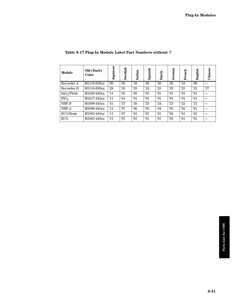
Plug-In Modules
Parts L
ist
for C
MS
Table 6-17 Plug-In Module Label Part Numbers without T
ModuleOld (Dark)
Color
Jap
an
ese
Sw
ed
ish
Itali
an
Span
ish
Du
tch
Germ
an
Fre
nch
En
gli
sh
Ch
inese
Recorder A M1116-830xx '90 '60 '50 '40 '20 '20 '10 '00 ---
Recorder B M1116-830xx '28 '26 '29 '24 '23 '23 '25 '21 ‘27
SaO2/Pleth M1020-443xx '11 '05 '05 '05 '01 '01 '01 '01 ---
FIO2 M1017-443xx '11 '01 '01 '01 '01 '01 '01 '01 ---
NBP B M1008-443xx '31 '27 '26 '25 '24 '23 '22 '21 ---
NBP A M1008-443xx '11 '07 '06 '05 '04 '03 '02 '01 ---
ECG/Resp M1002-443xx '11 '07 '01 '01 '01 '03 '01 '01 ---
ECG M1001-443xx '11 '07 '01 '01 '01 '03 '01 '01 ---
6-31

Plug-in Module Racks
Parts L
ist
for C
MS
Plug-in Module Racks
The parts that can be replaced on either the integral module rack or the satellite module rack are listed in the following table:
Handheld Keypad
The following table lists the replaceable parts for the:
• M1106A Classic Handheld Keypad (without Suspend Key)
• M1106B Classic Handheld Keypad
• M1106C Standard Handheld Keypad (available in two colors)
Table 6-18 Module Racks - Replaceable Parts
Exchange
Part Number
New
Part Number Description
M1043-68101 M1043-60101 INTEGRAL RACK
M1041-68101 M1041-60101 SATELLITE RACK
M1043-60102 BLANK RACK
M1043-40211 BLANK FRONT COVER (for Blank Rack)
M1041-44911 HANDLE EXT.RACK
M1041-44112 COVER CONNECT (EXT RACK)
MOUNTING CLAMP (EXT RACK)
Table 6-19 Handheld Keypad - Replaceable Parts
M1106A M1106B
M1106C
Old (Darker)
Color
M1106C
New (Lighter)
Color
Description
M1106-66000 M1106-66100 M1106-66200 M1106-66400 HANDHELD KEYPAD (ENGLISH)
M1106-66001 M1106-66101 M1106-66201 M1106-66401 HANDHELD KEYPAD (FRENCH)
M1106-66002 M1106-66102 M1106-66202 M1106-66402 HANDHELD KEYPAD (GERMAN)
M1106-66003 M1106-66103 M1106-66203 M1106-66403 HANDHELD KEYPAD (DUTCH)
M1106-66004 M1106-66104 M1106-66204 M1106-66404 HANDHELD KEYPAD (SPANISH)
M1106-66105 M1106-66205 M1106-66405 HANDHELD KEYPAD (ITALIAN)
M1106-66106 M1106-66206 M1106-66406 HANDHELD KEYPAD (TRADITIONAL CHINESE)
M1106-66109 M1106-66209 M1106-66409 HANDHELD KEYPAD (JAPANESE)
M1106-66108 M1106-66208 M1106-66408 HANDHELD KEYPAD (SWEDISH)
M1106-66116 M1106-66216 M1106-66414 HANDHELD KEYPAD (SIMPLIFIED CHINESE)
M1106-66412 HANDHELD KEYPAD (PORTUGUESE)
M1106-66111 M1106-66211 M1106-66411 HANDHELD KEYPAD (NORWEGIAN)
6-32

Handheld Keypad
Parts L
ist
for C
MS
M1106-66100 M1106-66210 M1106-66410 HANDHELD KEYPAD (FINNISH)
M1106-66413 HANDHELD KEYPAD (GREEK)
M1106-66415 HANDHELD KEYPAD (RUSSIAN)
M1106-66416 HANDHELD KEYPAD (POLISH)
M1106-66417 HANDHELD KEYPAD (CZECH)
M1106-60300 M1106-60300 M1106-60400 HOUSING ASSEMBLY, TOP AND BOTTOM
M1106-00110 M1106-00110 M1106-00210 MOUNTING BRACKET
M1106-60200 M1106-60200 M1106-60200 M1106-60200 CABLE ASSEMBLY
Table 6-20 Handheld Keypad - Overlay Part Numbers
M1106C Description
M1106-43100 KEYPAD OVERLAY (ENGLISH)
M1106-43101 KEYPAD OVERLAY (FRENCH)
M1106-43102 KEYPAD OVERLAY (GERMAN)
M1106-43103 KEYPAD OVERLAY (DUTCH)
M1106-43104 KEYPAD OVERLAY (SPANISH)
M1106-43105 KEYPAD OVERLAY (ITALIAN)
M1106-43106 KEYPAD OVERLAY (TRADITIONAL CHINESE)
M1106-43108 KEYPAD OVERLAY (SWEDISH)
M1106-43109 KEYPAD OVERLAY (JAPANESE)
M1106-43110 KEYPAD OVERLAY (FINNISH)
M1106-43111 KEYPAD OVERLAY (NORWEGIAN)
M1106-43116 KEYPAD OVERLAY (SIMPLIFIED CHINESE)
Table 6-19 Handheld Keypad - Replaceable Parts
M1106A M1106B
M1106C
Old (Darker)
Color
M1106C
New (Lighter)
Color
Description
6-33

Patient Connectors and Accessories
Parts L
ist
for C
MS
Patient Connectors and Accessories
General
ECG & ECG/Respiration Module Accessories
The cabling and associated parts that can be ordered for the ECG and ECG/Respiration modules are:
Table 6-21 General Accessories
New Part Number Description
M2281A Patient Cable Organizer (pack of 8 hooks)
M1520AM1510A
mrx-ecg1
6-34

Patient Connectors and Accessories
Parts L
ist
for C
MS
Table 6-22 ECG & ECG/Respiration Trunk Cables
US Standard IEC Standard
3 lead, 2.7m M1500A M1510A
3 lead, 0.4m M1540C M1550C
5 lead, 2.7m M1520A M1530A
5 lead, 0.4m M1560A M1570A
Table 6-23 ECG & ECG/Respiration One Piece Cables
US Standard IEC Standard
3 lead, OR, 1.9m M1970A M1980A
3 lead, ICU (Snap), 1.9m M1972A ----
3 lead, ICU (Grabber), 1.9m ---- M1981A
5 lead, OR, 2.5m M1975A M1985A
5 lead, ICU (Snap), 2.5m M1977A ----
5 lead, ICU (Grabber), 2.5m ---- M1986A
Table 6-24 ECG & ECG/Respiration OR Lead Sets
US Standard IEC Standard
OR 3 lead, 0.7m, Grabber M1601A M1611A
OR 5 lead, 0.7m 1.3m leg, Grabber M1621A M1631A
Table 6-25 ECG & ECG/Respiration Shielded Lead Sets
US Standard IEC Standard
Shielded 3 lead, 0.7m, Grabber M1603A M1613A
Shielded 3 lead, 0.7m, Snap M1605A M1615A
Shielded 5 lead, 0.7m (1.3m leg), Grabber M1623A M1633A
GrabberSnap
ClipConnector to
trunk cable
3-lead set
5-lead set
6-35

Patient Connectors and Accessories
Parts L
ist
for C
MS
Shielded 5 lead, 0.7m (1.3m leg), Snap M1625A M1635A
Table 6-26 ECG & ECG/Respiration Unshielded Lead Sets
US Standard IEC Standard
Unshld. 3 lead, 0.45m, Mini Clip M1608A M1618A
Unshld. 3 lead, 0.7m, Mini Clip M1609A M1619A
Unshld. 5 lead, 0.7m (1.3m leg), Mini Clip M1629A M1639A
Table 6-27 ECG & ECG/Respiration Single Leads
New Part
Number Description
New Part
NumberDescription
M1511A Grabber, OR, 0.7m, Black M1544A Snap, STD, 0.7m, White
M1512A Grabber, OR, 0.7m, Green M1545A Snap, STD, 0.7m, Yellow
M1513A Grabber, OR, 0.7m, Red M1546A Snap, STD, 0.7m, Brown
M1514A Grabber, OR, 0.7m, White M1547A Snap, STD, 1.3m, Black
M1515A Grabber, OR, 0.7m, Yellow M1548A Snap, STD, 1.3m, Green
M1516A Grabber, OR, 0.7m, Brown M1549A Snap, STD, 1.3m, Red
M1517A Grabber, OR, 1.3m, Black M1581A Clip, Uns, 0.7m, Black
M1518A Grabber, OR, 1.3m, Green M1582A Clip, Uns, 0.7m, Green
M1519A Grabber, OR, 1.3m, Red M1583A Clip, Uns, 0.7m, Red
M1521A Grabber, STD, 0.7m, Black M1584A Clip, Uns, 0.7m, White
M1522A Grabber, STD, 0.7m, Green M1585A Clip, Uns, 0.7m, Yellow
M1523A Grabber, STD, 0.7m, Red M1586A Clip, Uns, 0.7m, Brown
M1524A Grabber, STD, 0.7m, White M1587A Clip, Uns, 1.3m, Black
M1525A Grabber, STD, 0.7m, Yellow M1588A Clip, Uns, 1.3m, Green
M1526A Grabber, STD, 0.7m, Brown M1589A Clip, Uns, 1.3m, Red
M1527A Grabber, STD, 1.3m, Black M1591A Clip, Uns, 0.45m, Black
M1528A Grabber, STD, 1.3m, Green M1592A Clip, Uns, 0.45m, Green
M1529A Grabber, STD, 1.3m, Red M1593A Clip, Uns, 0.45m, Red
M1541A Snap, STD, 0.7m, Black M1594A Clip, Uns, 0.45m, White
M1542A Snap, STD, 0.7m, Green M1595A Clip, Uns, 0.45m, Yellow
M1543A Snap, STD, 0.7m, Red
Table 6-28 ECG & ECG/Respiration Cabling Accessories
for 3 lead sets for 5 lead sets
Combiner block M1501A M1502A
Cable organizer (shielded and OR cables) M1503A M1504A
Cable organizer (unshielded cables) M1505A M1506A
Bedsheet clip, repositionable M1509A
Table 6-29 EASI Accessories
US Non-US
EASI Stickers 5967-2090 5967-2084
Table 6-25 ECG & ECG/Respiration Shielded Lead Sets
US Standard IEC Standard
6-36

Patient Connectors and Accessories
Parts L
ist
for C
MS
Pressure Module Accessories
The following accessories can be ordered for the Pressure Module:
Table 6-30 PRESS Transducers & Adapter Cables
New Part Number Description
1290C #J06 Pressure Transducer with 3m cable & 12-pin connector
1290C #J99-11 Pressure Transducer with 1m cable & 12-pin connector
1295CK Sterile domes
Table 6-31 PRESS Transducer Accessories
New Part Number Description
1292C Holder for two 1290C Transducers
1293C Holder for three 1290C Transducers
1294C Holder for four 1290C Transducers
Table 6-32 M1006B Pressure Module with Analog Output - Cables
New Part Number Description
M1181A #A61 3 m IABP Cable
M1181A #A6B 25 m IABP Cable
1295CK1290C
mrx-prs1
DONOTPULL
CABLES(TRANSDUCER)
1292C
mrx-prs2
6-37

Patient Connectors and Accessories
Parts L
ist
for C
MS
Non-Invasive Pressure Module Accessories
The following accessories can be ordered for the Non-Invasive Pressure Module:
Table 6-33 Pressure Cuffs & Interconnection Cables
New Part Number Description
40401A Reusable pressure cuff, infant, 10-19cm
40401B Reusable pressure cuff, pediatric, 18-26cm
40401C Reusable pressure cuff, adult, 25-35cm
40401D Reusable pressure cuff, large arm, 33-47cm
40401E Reusable pressure cuff, thigh, 46-66cm
40400A Reusable pressure cuff kit, includes 40401B/C/D
40400B Reusable pressure cuff kit, includes 40401A/B/C/D/E
M1571A Reusable Pressure cuff, infant, 12-17.5cm
M1572A Reusable Pressure cuff, pediatric, 17-24cm
M1573A Reusable Pressure cuff, small adult, 22-32cm
M1574A Reusable Pressure cuff, adult, 27-37.5cm
M1575A Reusable Pressure cuff, large adult, 37-51cm
M1576A Reusable Pressure cuff, thigh size, 45-60cm
M1577A Reusable Pressure cuff, kit, includes M1571/2/3/4A
M1578A Reusable Pressure cuff, kit, includes M1573/4/5/6A
M1579A Reusable Pressure cuff, kit, includes M1571/2/3/4/5/6A
M1874A Non-sterile disposable pressure cuff, infant,12.0-17.5cm
M1875A Non-sterile disposable pressure cuff, pediatric,17-24cm
M1808A/M1876A Sterile/Non-sterile disposable pressure cuff, adult, 22-32cm
NBP - Accessories
40401D
A BC D
40401C
A BC D
40401B
A BC D
40401A
AB
C D
40401E
E
40400B
40401A40401B
40401C40401D
40401E
mrx-nbp
6-38

Patient Connectors and Accessories
Parts L
ist
for C
MS
M1809A/M1877A Sterile/Non-sterile disposable pressure cuff, adult, 27-37.5cm
M1829A/M1078A Sterile/Non-sterile disposable pressure cuff, adult, 37-51cm
M1879A Non-sterile disposable pressure cuff, thigh, 45-60cm
M1867A/M1866A Sterile/Non-sterile disposable neonatal cuff, size 1, 3.1-5.7cm
M1869A/M1868A Sterile/Non-sterile disposable neonatal cuff, size 2, 4.3-8.0cm
M1879A/M1870A Sterile/Non-sterile disposable neonatal cuff, size 3, 5.8-10.9cm
M1873A/M1872A Sterile/Non-sterile disposable neonatal cuff, size 4,7.1-13.1cm
M1597 Neonatal interconnect cable, 3m
M1596 Neonatal interconnect cable, 1.5m
M1599 Adult interconnect cable, 3m
M1598 Adult interconnect cable, 1.5m
40401-40010 Cap for liquid seal
Table 6-33 Pressure Cuffs & Interconnection Cables
New Part Number Description
6-39

Patient Connectors and Accessories
Parts L
ist
for C
MS
Cardiac Output Module Accessories
The following accessories can be ordered for the Cardiac Output Module:
Table 6-34 Cardiac Output Temperature Probes & Accessories
Part
Number Description
Used with
Right
Heart
method
Transpul
monary
methoda
a. only available with Option C10
14454A IV pole mount x x
14455A Ice bucket for Cardiac Output; styrofoam x x
15244A Hand switch x x
23001A Reusable Injectate Temp. Probe for Baxter C.O. Set 2.4m x x
23001B Reusable Injectate Temp. Probe for Baxter C.O. Set 0.5m x x
M1646A Reusable Injectate Temp. Probe for Pulsion Set x
23002A Ice bath reusable static temp.probe x
M1642A Cardiac Output cable, 2.7m + 0.2m x
M1643A Enhanced Cardiac Output interface cable, 2.4m + 2.4m x x
Table 6-35 General Cardiac Output Accessories
Part Number Description
M1012-61601 Cardiac Output Service Toolto check proper function of M1012A, M1042A, M1043A
23002A 23001A14455A
6-40

Patient Connectors and Accessories
Parts L
ist
for C
MS
CO2 Module Accessories
The following accessories can be ordered for the CO2 Module:
Table 6-36 CO2 Gas Monitoring Accessories
New Part Number Description
14360A Airway CO2 transducer with calstick (obsolete)
M1460A Airway CO2 transducer with calstick
14363A Reusable pediatric airway adapter
14365A Reusable adult airway adapter
14373B Disposable 15mm airway tubing couplers (IEC)
14373C Disposable 15mm airway tubing couplers (Non-IEC)
To Patient
Y-Piece
ExpiratoryLimb
To AnesthesiaMachine
To AnesthesiaMachine
InspiratoryLimb
14363A
14365A
14360A
14373C
mrx-co2
6-41

Patient Connectors and Accessories
Parts L
ist
for C
MS
Sidestream CO2 Module Accessories
The following accessories can be ordered for the Sidestream CO2 Module:
SvO2 Module Accessories
All SvO2 Module accessories are available from Abbott.
Table 6-37 Sidestream CO2 Gas Monitoring Accessories
New Part Number Description
13901A Sample tube, 2.4 m Nafion
13902A Elbow airway adaptor, 15 mm
1612AA Straight airway adaptor
13904A Bacterial Filter
13905A Hybrid Sample Tube
Table 6-38 SvO2 Monitoring Accessories
Abbott Part Number Description
50131-04 Optical Module
P7110-EH Opticath Fiber-Optic Catheters
P7110-E
P7110-EP-H
P7110-EP8-H
P7110-EP8
P7110-PZ8-H
P575-EH10CM
P575-EH
6-42

Patient Connectors and Accessories
Parts L
ist
for C
MS
FIO2 Module Accessories
The following accessories can be ordered for the FIO2 Module:
Table 6-39 FIO2 Gas Monitoring Accessories
New Part Number Description
15203A Inspired air oxygen transducer
To Patient
Y-Piece
Expiratory
Limb
To Anesthesia
Machine
To Anesthesia
Machine
Connects
to Module
Inspiratory
Limb
2
15203A
mrx-fio2
6-43

Patient Connectors and Accessories
Parts L
ist
for C
MS
SpO2 Module Accessories
The following accessories can be ordered for the SpO2 Module:
Temperature Module Accessories
The following accessories can be ordered for the Temperature Module:
Table 6-40 SpO2 Monitoring Accessories
New Part Number Description
M1190A Adult SpO2 transducer, no adapter cable required.
M1191A Adult SpO2 transducer, requires M1940 adapter cable.
M1192A Small Adult/Pediatric SpO2 transducer, requires M1940 adapter cable.
M1193A Neonatal SpO2 transducer, requires M1940 adapter cable.
M1194A Adult/Pedi SpO2 transducer, requires M1940 adapter cable.
M1195A Infant SpO2 transducer, requires M1940 adapter cable.
M1904A Disposable NELLCOR® OxisensorIITM adult digit sensor, sterile.
M1903A Disposable NELLCOR® OxisensorIITM pediatric digit sensor, sterile.
M1902A Disposable NELLCOR® OxisensorIITM infant digit sensor, sterile.
M1901A Disposable NELLCOR® OxisensorIITM neonatal foot sensor, sterile.
M1907A Semi-disposable NELLCOR® Oxiband adult/neonatal sensor, non-sterile
M1906A Semi-disposable NELLCOR® Oxiband pediatric/infant sensor, non-sterile
M1940A Adapter cable for use with HP/Agilent/Philips Transducers.
M1900B Adapter cable for use with NELLCOR® Transducers.
Table 6-41 Temperature Probes - Disposable
New Part Number Description
21082A Extension cable for disposable temp. probes, 3m
21082B Extension cable for disposable temp. probes, 1.5m
21090A Disposable general purpose temp. probe
21091A Disposable skin surface temp. probe
21093A Disposable esophageal/stethoscope temp. probe, 12fr
21094A Disposable esophageal/stethoscope temp. probe, 18fr
21095A Disposable esophageal/stethoscope temp. probe, 24fr
21096A Disposable Foley Catheter temp. probe, 16fr
21097A Disposable Foley Catheter temp. probe, 18fr
Table 6-42 Temperature Probes - Reusable
New Part Number Description
21075A General purpose temp. probe; reusable
21075B General purpose temp. probe; reusable (Germany)
21076A Small flexible temp. probe; reusable
21076B Small flexible temp. probe; reusable (Germany)
21078A Skin surface temp. probe; tape-on; reusable
21078B Skin surface temp. probe; tape-on; reusable (Germany)
6-44

Patient Connectors and Accessories
Parts L
ist
for C
MS
tcpO2/tcpCO2 Module Accessories
The following accessories can be ordered for the tcpO2/tcpCO2 Module:
Thermal Array Recorder Module Accessories
The following accessories can be ordered for the Recorder Module:
Blood Analysis Module Accessories
The following accessories can be ordered for the Blood Analysis Module.
Table 6-43 tcpO2/tcpCO2 Monitoring Accessories
New Part Number Description
M15209-60010 Accessory Kit
M15210-60010 CAL 1 gas (6 bottles - U.S.A. only)
M15210-64010 CAL 1 gas (6 bottles)
M15210-60020 CAL 2 gas (6 bottles - U.S.A. only) Contains: 0% O2, 10% CO2M15210-64020 CAL 2 gas (6 bottles) Contains: 0% O2, 10% CO2M1918A tcpO2/CO2 Transducer
M2205A Calibration Tubing (5x)
Table 6-44 Thermal Array Recorder Accessories
New Part Number Description
40477A 10 ROLLS THERMAL RECORDER PAPER
40477B 80 ROLLS THERMAL RECORDER PAPER
Table 6-45 Blood Analysis Cartridges
Part Number Descriptionorder from Abbott EG7+ Cartridge
order from Abbott EG6+ Cartridge
order from Abbott G3+ Cartridge
order from Abbott EC8+ Cartridge
order from Abbott 6+ Cartridge
order from Abbott EC6+ Cartridge
order from Abbott EC4+ Cartridge
order from Abbott G Cartridge
order from Abbott E3+
order from Abbott Creatinine Cartridge
order from Abbott CG4+ Cartridge
Table 6-46 Blood Analysis Accessories
Part Number Description
order from Abbott Level 1 Control
order from Abbott Level 3 Control
6-45

Patient Connectors and Accessories
Parts L
ist
for C
MS
EEG Module Accessories
The following accessories can be ordered for the EEG Module.
VueLink Test Module Parts
The VueLink Test Module is a plug-in module used to test M1032A VueLink Modules. The following parts can be ordered.
M3630A Calibration Verification Set
M3636A Capillary Tubes (65 µl)
M3634A Electronic Simulator
M3663A PC to RS232 Adapter cable for upgrading modules using IBM-compatible PC
Table 6-47 EEG Module Accessories
Part Number Description
M2268A EEG 2.7 m trunk cable
M2269A EEG 1.0 m trunk cable
M1931A Reusable 80-cm-long 5-lead cables with 10-mm silver/silverchloride leadwired cup electrodes (adult)
M1932A Reusable 80-cm-long 5-lead cables with 6-mm silver/silverchloride leadwired cup electrodes (Pediatric/Neonatal)
M1934A Reusable 80-cm-long 5-lead cables with miniclip connectors
M1935A Disposable, gel electrodes (50)
M2271A Skin preparation paste
M2272A Conductive paste
M1027-88000 EEG Test Device
Table 6-48 VueLink Test Module Parts
Part Number Description
M1186-60510 VueLink Test Module
M1032-61661 Cable
Table 6-46 Blood Analysis Accessories (Continued)
Part Number Description
6-46

t I
nfo
rm
ati
on
Appendix A Product Information
Pro
du
c
CMS Release E Beta
Option A54
Option A64
Option A56
Option A66Option A68
Display Module
Mono / Color Mono (Option A54) Color (Option A64)
Mono (OptionA56) Color (Option A66)
Color
Number of Channels 4 6 8
Supported Remote Displays 3 3 3
Plug-in Modules
Maximum Number of Parameter Modules 8 12 16
Supported Modules
M1001A/B ECG (1) 1 1 1
M1002A/B ECG/RESP (1) 1 1 1
M1006A/B Invasive Pressure 3 5 6
M1008A/B NBP 1 1 1
M1012A Cardiac Output 1 1 1
M1015A Sidestream CO2 1 1 1
M1016A CO2 1 1 1
M1017A FiO2 1 1 1
M1018A tcpO2/tcpCO2 1 1 1
M1020A SpO2/Pleth 1 1 1
M1021A SvO2 1 1 1
M1029A Temperature 2 (1 Delta Temp.) 4 (2 Delta Temp.) 4 (2 Delta Temp.)
M1032A VueLink Type A 2 2 3
M1032A VueLink Type B 1 2 2
M1116A/B Recorder Module 1 1 1
M1235A Data Transfer Module 1 1 1
Patient Data Management (Standard)
Data Storage1 min. resolution
12 sec. resolution
16 parameters / 24 hours
16 parameters / 4 hours
16 parameters / 24 hours
16 parameters / 4 hours
32 parameters / 24 hours(16 parameters / 48 hours)32 parameters / 4 hours(16 parameters / 9 hours)
Trends Tabular / Graphic Tabular / Graphic Tabular / Graphic
Clinical Calculations • Hemodynamic• Oxygenation• Ventilation
• Hemodynamic• Oxygenation• Ventilation
• Hemodynamic• Oxygenation• Ventilation
Software Applications
Extended Data Management — Option C03 Standard
1 min. resolution 32 parameters / 24 hours(16 parameters / 48 hours)
12 sec. resolution 32 parameters / 4 hours(16 parameters / 9 hours)
Drug Calculator Option C05 Option C05 Standard
ST Segment Analysis Option C10 Option C10 Standard
(1) M1001A/B and M1002A/B cannot be used simultaneously in a system.
Product Information A-1

CMS Release E Beta
Pro
du
ct I
nfo
rm
ati
on
Interfacing and Networking Capabilities
8-Channel Analog Interface — Option J11 Option J11
Philips Network Interface (Standard in US) Option J12 Option J12 Option J12
1st RS232 Interface Option J13 Option J13 Option J13
2nd RS232 Interface — — Option J13
Digital Recorder Interface Option J14 Option J14 Option J14
1st additional Display Interface — Option J15 (color) orOption J16 (mono)
Option J15 (color) orOption J16 (mono)
2nd additional Display Interface -— — Option J16 (mono)(1)
Peripherals
Remote Keypad (Standard US) M1106C M1106C M1106C
4 Channel Recorder M1117A M1117A M1117A
8-Slot Satellite Rack M1041A M1041A M1041A
6-Slot Satellite Rack M1276A M1276A M1276A
14 Inch Monochrome Display — M1092A (Option A03) M1092A (Option A03)
14 Inch Color Display — M1094B (Option A03) M1094B (Option A03)
21 Inch Color Display — M1234B M1234B
Substitute Options
Substitute 8-slot Satellite Rack for Integral Rack
Option H50 Option H50 Option H50
Substitute 6-slot Satellite Rack forIntegral Rack
Option H52 Option H52 Option H52
Substitute Classic HIF for Standard HIF(2) Option H60 Option H60 Option H60
Substitute short System Cable Option K01 Option K01 Option K01
Substitute 3 meter System Cable Option K02 Option K02 Option K02
Substitute 1.5 meter System Cable Option K03 Option K03 Option K03
Substitute 0.75 meter System Cable Option K04 Option K04 Option K04
Option A54
Option A64
Option A56
Option A66Option A68
(1) A 2nd independent monochrome display controller (option J16) and the 8-channel analog interface are not supported simultaneously.(2) The M1106B Handheld keypad must be ordered separately.
A-2 Product Information

ACMS Release E Beta
Pro
du
ct I
nfo
rm
ati
on
ACMS Release E Beta
Option A74
Option A84
Option A76
Option A86Option A88
Display Module
Mono / Color Mono (Option A74)Color (Option A84)
Mono (Option A76)Color (Option A86)
Color
Number of Channels 4 6 8
Supported Remote Displays 3 3 3
Plug-in Modules
Max. Number of Parameter Modules 8 12 16
Supported Modules
M1001A/B ECG (1) 1 1 1
M1002A/B ECG/RESP (1) 1 1 1
M1006A/B Invasive Pressure 3 5 6
M1008A/B NBP 1 1 1
M1012A Cardiac Output 1 1 1
M1015A Sidestream CO2 1 1 1
M1016A CO2 1 1 1
M1017A FiO2 1 1 1
M1020A SpO2/Pleth 1 1 1
M1021A SvO2 1 1 1
M1029A Temperature 2 (1 Delta Temp.) 4 (2 Delta Temp.) 4 (2 Delta Temp.)
M1032A VueLink Type A 1 (2 with Option C24) 1 (2 with Option C25) 3
M1032A VueLink Type B(2) 1 1 (2 with Option C25) 2
M1116A/B Recorder Module 1 1 1
M1235A Data Transfer Module 1 1 1
Anesthesia Gas Monitoring
M1026A Anesthetic Gas Module 1 1 1
Patient Data Management
Data Storage1 min. resolution
12 sec. resolution
16 parameters / 24 hours
16 parameters / 4 hours
16 parameters / 24 hours
16 parameters / 4 hours
32 parameters / 24 hours(16 parameters / 48 hours)32 parameters / 4 hours(16 parameters / 9 hours)
Trends Tabular / Graphic Tabular / Graphic Tabular / Graphic
Clinical Calculations • Hemodynamic• Oxygenation• Ventilation
• Hemodynamic• Oxygenation• Ventilation
• Hemodynamic• Oxygenation• Ventilation
(1) M1001A/B and M1002A/B cannot be used simultaneously in a system.(2) The ACMS does not support VueLink Option #A02.
Software Applications
Extended Data Management — Option C03 Standard
1 min. resolution 32 parameters / 24 hours(16 parameters / 48 hours)
12 sec. resolution 32 parameters / 4 hours(16 parameters / 9 hours)
Product Information A-3

ACMS Release E Beta
Pro
du
ct I
nfo
rm
ati
on
Drug Calculator Option C05 Option C05 Standard
ST Segment Analysis Standard Standard Standard
Interface Accelerator Option C24• Supports 1 additional
VueLink Module(Type A)
• Supports Philips Network capability
Option C25• Supports independent
display controller• Supports 2 additional
VueLink Modules (Type A, Type B)
• Supports Philips Network capability
Standard
Interfacing and Networking Capabilities
8-Channel Analog Interface — Option J11 Option J11(1)
Philips Network Interface Option J12 with Option C24 Option J12 with Option C25 Option J12
1st RS232 Dual Interface(2) Standard Standard Standard
2nd RS232 Dual Interface Option J13 Option J13 Option J13
Delete 1st RS232 Dual Interface(2) Option D13 Option D13 Option D13
Digital Recorder Interface Option J14 Option J14 Option J14
1st additional Display Interface — Option J15 (color) orOption J16 (mono) both with Option C25
Option J15 (color) orOption J16 (mono)
2nd additional Display Interface — — Option J16 (mono) (1)
Peripherals
Remote Keypad (Standard US) M1106C M1106C M1106C
4 Channel Recorder M1117A M1117A M1117A
8-Slot Satellite Rack M1041A M1041A M1041A
6-Slot Satellite Rack M1276A M1276A M1276A
14 Inch Monochrome Display — M1092A (Option A03) M1092A (Option A03)
14 Inch Color Display — M1094B (Option A03) M1094B (Option A03)
21 Inch Color Display — M1234B M1234B
Substitute Options
Substitute 8-slot Satellite Rack forIntegral Rack
Option H50 Option H50 Option H50
Substitute 6-slot Satellite Rack forIntegral Rack
Option H52 Option H52 Option H52
Substitute short System Cable Option K01 Option K01 Option K01
Substitute 3.0 meter System Cable Option K02 Option K02 Option K02
Substitute 1.5 meter System Cable Option K03 Option K03 Option K03
Substitute 0.75 meter System Cable Option K04 Option K04 Option K04
(1) A 2nd independent monochrome display controller (option J16) and an 8-channel analog interface are not supportedsimultaneously.
(2) Includes a 3.0 meter RS232 cable.
Option A74
Option A84
Option A76
Option A86Option A88
A-4 Product Information

CMS Release F
Pro
du
ct I
nfo
rm
ati
on
CMS Release F
M1175A Option A54
M1176A Option A64
M1175A Option A56
M1176A Option A66M1176A Option A68
Display Module
Mono / Color Mono (Option A54) Color (Option A64)
Mono (Option A56) Color (Option A66)
Color
Number of Channels 4 6 8
Supported Remote Displays 3 3 3
Plug-in Modules
Maximum Number of Parameter Modules 8 12 16
Supported Modules
M1001A/B ECG (1) 1 1 1
M1002A/B ECG/RESP (1) 1 1 1
M1006A/B Invasive Pressure 3 5 6
M1008A/B NBP 1 1 1
M1012A Cardiac Output 1 1 1
M1015A Sidestream CO2(2) 1 1 1
M1016A CO2 1 1 1
M1017A FIO2 1 1 1
M1018A tcpO2/tcpCO2 1 1 1
M1020A SpO2/Pleth 1 1 1
M1021A SvO2 1 1 1
M1029A Temperature 2 (1 Delta Temp.) 4 (2 Delta Temp.) 4 (2 Delta Temp.)
M1032A VueLink Type A 2 2 3
M1032A VueLink Type B 1 2 2
M1116A/B Recorder Module 1 1 1
M1235A Data Transfer Module 1 1 1
Patient Data Management (Standard)
Data Storage1 min. resolution
12 sec. resolution
16 parameters / 24 hours
16 parameters / 4 hours
16 parameters / 24 hours
16 parameters / 4 hours
32 parameters / 24 hours(16 parameters / 48 hours)32 parameters / 4 hours(16 parameters / 9 hours)
Trends Tabular / Graphic Tabular / Graphic Tabular / Graphic
Clinical Calculations • Hemodynamic• Oxygenation• Ventilation
• Hemodynamic• Oxygenation• Ventilation
• Hemodynamic• Oxygenation• Ventilation
Software Applications
Extended Data Management — Option C03 Standard
1 min. resolution 32 parameters / 24 hours(16 parameters / 48 hours)
12 sec. resolution 32 parameters / 4 hours(16 parameters / 9 hours)
Drug Calculator Option C05 Option C05 Standard
ST Segment Analysis Option C10 Option C10 Standard
(1) M1001A/B and M1002A/B cannot be used simultaneously in a system.(2)Pending FDA clearance.
Product Information A-5

CMS Release F
Pro
du
ct I
nfo
rm
ati
on
(1) A 2nd independent monochrome display controller (option J16) and the 8-channel analog interface are not supported simultaneously. (2)Includes isolation transformer.
Interfacing and Networking Capabilities
8-Channel Analog Interface — Option J11 Option J11
Philips Network Interface Standard Standard Standard
1st RS232 Interface Option J13 Option J13 Option J13
2nd RS232 Interface — ----- Option J13
Digital Recorder Interface Option J14 Option J14 Option J14
1st additional Display Interface — Option J15 (color) orOption J16 (mono)
Option J15 (color) orOption J16 (mono)
2nd additional Display Interface — — Option J16 (mono)(1)
1st additional Flatscreen Display Interface — Option J25 (M1095A) Option J25 (M1095A)
Peripherals
Remote Keypad Standard Standard Standard
4 Channel Recorder M1117A M1117A M1117A
8-Slot Satellite Rack M1041A M1041A M1041A
6-Slot Satellite Rack M1276A M1276A M1276A
14 Inch Monochrome Display — M1092A (Option A03) M1092A (Option A03)
14 Inch Color Display — M1094B (Option A03) M1094B (Option A03)
10.4 Inch Flatscreen Color Display — M1095A (Option A03) M1095A (Option A03)
21 Inch Color Display(2) — M1175/6A (Option H71) M1175/6A (Option H71)
Substitute Options
Substitute Flatscreen Display — Option H01 Option H01
Substitute 8-slot Satellite Rack for Integral Rack
Option H50 Option H50 Option H50
Substitute 6-slot Satellite Rack forIntegral Rack
Option H52 Option H52 Option H52
Substitute Classic HIF for Standard HIF Option H60 Option H60 Option H60
Substitute short System Cable Option K01 Option K01 Option K01
Substitute 3 meter System Cable Option K02 Option K02 Option K02
Substitute 1.5 meter System Cable Option K03 Option K03 Option K03
M1175A Option A54
M1176A Option A64
M1175A Option A56
M1176A Option A66M1176A Option A68
A-6 Product Information

ACMS Release F
Pro
du
ct I
nfo
rm
ati
on
ACMS Release F
M1175A Option A74
M1176A Option A84
M1175A Option A76
M1176A Option A86M1176A Option A88
Display Module
Mono / Color Mono A74 / Color A84 Mono A76 / Color A86 Color
Number of Channels 4 6 8
Supported Remote Displays 3 3 3
Plug-in Modules
Max. Number of Parameter Modules 8 12 16
Supported Modules
M1001A/B ECG (1) 1 1 1
M1002A/B ECG/RESP (1) 1 1 1
M1006A/B Invasive Pressure 3 5 6
M1008A/B NBP 1 1 1
M1012A Cardiac Output 1 1 1
M1015A Sidestream CO2 1 1 1
M1016A CO2 1 1 1
M1017A FIO2 1 1 1
M1020A SpO2/Pleth 1 1 1 (2 with Option C11)
M1021A SvO2 1 1 1
M1029A Temperature 2 (1 Delta Temp.) 4 (2 Delta Temp.) 4 (2 Delta Temp.)
M1032A VueLink Type A 1 (2 with Option C24) 1 (2 with Option C25) 3
M1032A VueLink Type B 1 1 (2 with Option C25) 2
M1116A/B Recorder Module 1 1 1
M1235A Data Transfer Module 1 1 1
Anesthesia Gas Monitoring
M1026A Anesthetic Gas Module 1 1 1
Patient Data Management
Data Storage1 min. resolution
12 sec. resolution
16 parameters / 24 hours
16 parameters / 4 hours
16 parameters / 24 hours
16 parameters / 4 hours
32 parameters / 24 hours(16 parameters / 48 hours)32 parameters / 4 hours(16 parameters / 9 hours)
Trends Tabular / Graphic Tabular / Graphic Tabular / Graphic
Clinical Calculations • Hemodynamic• Oxygenation• Ventilation
• Hemodynamic• Oxygenation• Ventilation
• Hemodynamic• Oxygenation• Ventilation
Software Applications
Extended Data Management — Option C03 Standard
1 min. resolution 32 parameters / 24 hours(16 parameters / 48 hours)
12 sec. resolution 32 parameters / 4 hours(16 parameters / 9 hours)
Drug Calculator Option C05 Option C05 Standard
Dual SpO2 — — Option C11
(1) M1001A/B and M1002A/B cannot be used simultaneously in a system.
ST Segment Analysis Standard Standard Standard
Product Information A-7
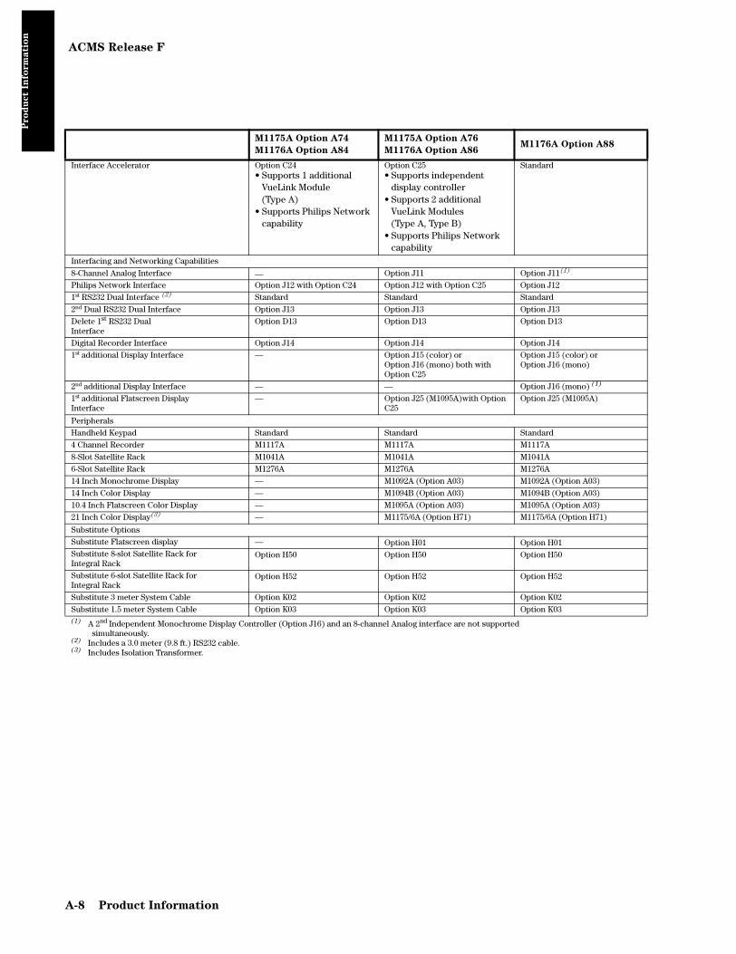
ACMS Release F
Pro
du
ct I
nfo
rm
ati
on
Interface Accelerator Option C24• Supports 1 additional
VueLink Module(Type A)
• Supports Philips Network capability
Option C25• Supports independent
display controller• Supports 2 additional
VueLink Modules (Type A, Type B)
• Supports Philips Network capability
Standard
Interfacing and Networking Capabilities
8-Channel Analog Interface — Option J11 Option J11(1)
Philips Network Interface Option J12 with Option C24 Option J12 with Option C25 Option J12
1st RS232 Dual Interface (2) Standard Standard Standard
2nd Dual RS232 Dual Interface Option J13 Option J13 Option J13
Delete 1st RS232 Dual Interface
Option D13 Option D13 Option D13
Digital Recorder Interface Option J14 Option J14 Option J14
1st additional Display Interface — Option J15 (color) orOption J16 (mono) both with Option C25
Option J15 (color) orOption J16 (mono)
2nd additional Display Interface — — Option J16 (mono) (1)
1st additional Flatscreen Display Interface
— Option J25 (M1095A)with Option C25
Option J25 (M1095A)
Peripherals
Handheld Keypad Standard Standard Standard
4 Channel Recorder M1117A M1117A M1117A
8-Slot Satellite Rack M1041A M1041A M1041A
6-Slot Satellite Rack M1276A M1276A M1276A
14 Inch Monochrome Display — M1092A (Option A03) M1092A (Option A03)
14 Inch Color Display — M1094B (Option A03) M1094B (Option A03)
10.4 Inch Flatscreen Color Display — M1095A (Option A03) M1095A (Option A03)
21 Inch Color Display(3) — M1175/6A (Option H71) M1175/6A (Option H71)
Substitute Options
Substitute Flatscreen display — Option H01 Option H01Substitute 8-slot Satellite Rack for Integral Rack
Option H50 Option H50 Option H50
Substitute 6-slot Satellite Rack forIntegral Rack
Option H52 Option H52 Option H52
Substitute 3 meter System Cable Option K02 Option K02 Option K02
Substitute 1.5 meter System Cable Option K03 Option K03 Option K03(1) A 2nd Independent Monochrome Display Controller (Option J16) and an 8-channel Analog interface are not supported
simultaneously.(2) Includes a 3.0 meter (9.8 ft.) RS232 cable.(3) Includes Isolation Transformer.
M1175A Option A74
M1176A Option A84
M1175A Option A76
M1176A Option A86M1176A Option A88
A-8 Product Information

NCMS Release F
Pro
du
ct I
nfo
rm
ati
on
NCMS Release F
M1175A Option A36
M1176A Option A46M1176A Option A48
Display Module
Mono / Color Mono (Option A36) Color (Option A46)
Color
Number of Channels 6 8
Plug-in Modules
Maximum Number of Parameter Modules 12 16
Supported Modules
M1001A/B ECG (1) 1 1
M1002A/B ECG/RESP (1) 1 1
M1006A/B Invasive Pressure 3 4
M1008A/B NBP 1 1
M1012A Cardiac Output 1 1
M1015A Sidestream CO2(2) 1 1
M1016A CO2 1 1
M1017A FIO2 1 1
M1018A tcpO2/tcpCO2 1 1
M1020A SpO2/Pleth 2 2
M1021A SvO2 1 1
M1029A Temperature 4 (2 Delta Temp.) 4 (2 Delta Temp.)
M1032A VueLink Type A 2 3
M1032A VueLink Type B 2 2
M1116A/B Recorder Module 1 1
M1235A Data Transfer Module 1 1
Patient Data Management (Standard)
Data Storage1 min. resolution
12 sec. resolution
16 parameters / 24 hours
16 parameters / 4 hours
32 parameters / 24 hours(16 parameters / 48 hours)32 parameters / 4 hours(16 parameters / 9 hours)
Trends Tabular / Graphic Tabular / Graphic
Clinical Calculations • Hemodynamic• Oxygenation• Ventilation
• Hemodynamic• Oxygenation• Ventilation
Software Applications
Drug Calculator Standard Standard
ST Segment Analysis Option C10 Standard
(1) M1001A/B and M1002A/B cannot be used simultaneously in a system.(2)Pending FDA clearance.
Product Information A-9

NCMS Release F
Pro
du
ct I
nfo
rm
ati
on
Interfacing and Networking Capabilities
8-Channel Analog Interface Option J11 Option J11
Philips Network Interface Standard Standard
1st RS232 Interface Option J13 Option J13
2nd RS232 Interface ----- Option J13
Digital Recorder Interface Option J14 Option J14
Peripherals
Remote Keypad Standard Standard
4 Channel Recorder M1117A M1117A
8-Slot Satellite Rack M1041A M1041A
6-Slot Satellite Rack M1276A M1276A
Substitute Options
Substitute Flatscreen Display Option H01 Option H01
Substitute 8-slot Satellite Rack for Integral Rack
Option H50 Option H50
Substitute 6-slot Satellite Rack forIntegral Rack
Option H52 Option H52
Substitute short System Cable Option K01 Option K01
Substitute 3 meter System Cable Option K02 Option K02
Substitute 1.5 meter System Cable Option K03 Option K03
M1175A Option A36
M1176A Option A46M1176A Option A48
A-10 Product Information

CMS Release G
Pro
du
ct I
nfo
rm
ati
on
CMS Release G
M1175A Option A54
M1176A Option A64
M1177A Option A64
M1175A Option A56
M1176A Option A66
M1177A Option A66
M1176A Option A68
M1177A Option A67
Display Module
Mono / Color Mono (Option A54) Color (Option A64)
Mono (OptionA56) Color (Option A66)
Color
Number of Channels 4 6 8
Supported Remote Displays (CRT) 3 3 3
Plug-in Modules
Maximum Number of Parameter Modules 8 12 16
Supported Modules
M1001A/B ECG (A) 1 1 1
M1002A/B ECG/RESP (A) 1 1 1
M1002A ECG/RESP with Analog Respiration Output (A) (B)
1 (with Option C01) 1 (with Option C01) 1 (with Option C01)
M1006A/B Invasive Pressure 3 5 6
M1006A/B Invasive Pressure withAnalog Pressure Output
3 (with Option C01) 5 (with Option C01) 6 (with Option C01)
M1008A/B NBP (B) 1 1 1
M1012A Cardiac Output 1 1 1
M1015A Sidestream CO2 1 1 1
M1016A CO2 1 1 1
M1017A FIO2 1 1 1
M1018A tcpO2/tcpCO2 (B) 1 1 1
M1020A SpO2/Pleth 1 1 1
M1021A SvO2 1 1 1
M1022A Blood Analysis (B) 1 1 1
M1029A Temperature 2 (1 Delta Temp.) 4 (2 Delta Temp.) 4 (2 Delta Temp.)
M1032A VueLink Type A 2 2 3
M1032A VueLink Type B 1 2 2
M1116A/B Recorder Module (B) 1 1 1
M1235A Data Transfer Module 1 1 1
Patient Data Management (Standard)
Data Storage1 min. resolution
12 sec. resolution
16 parameters / 24 hours
16 parameters / 4 hours
16 parameters / 24 hours
16 parameters / 4 hours
32 parameters / 24 hours(16 parameters / 48 hours)32 parameters / 4 hours(16 parameters / 9 hours)
Trends Tabular / Graphic Tabular / Graphic Tabular / Graphic
Clinical Calculations • Hemodynamic• Oxygenation• Ventilation
• Hemodynamic• Oxygenation• Ventilation
• Hemodynamic• Oxygenation• Ventilation
Software Applications
Extended Data Management — Option C03 Standard
1 min. resolution 32 parameters / 24 hours(16 parameters / 48 hours)
12 sec. resolution 32 parameters / 4 hours(16 parameters / 9 hours)
Drug Calculator Standard Standard Standard
ST Segment Analysis Option C10 Option C10 Standard
Product Information A-11

CMS Release G
Pro
du
ct I
nfo
rm
ati
on
(A) M1001A/B and M1002A/B cannot be used simultaneously in a system.(B)Each module requires 2 slots in the integral and/or Satellite Rack.(1)Includes isolation transformer.(2)Not available with Model M1175A.(3)Not available with Model M1177A.
Interfacing and Networking Capabilities
8-Channel Analog Interface — Option J11 Option J11
Philips Network Interface Standard Standard Standard
1st RS232 Interface Option J13 Option J13 Option J13
2nd RS232 Interface — ----- Option J13
Digital Recorder Interface Option J14 Option J14 Option J14
1st additional Display or FlatscreenInterface
— Option J15 (color) orOption J16 (mono) orOption J25 (Flatscreen)
Option J15 (color) orOption J16 (mono) orOption J25 (Flatscreen)
Peripherals
Remote Keypad Standard Standard Standard
4 Channel Recorder M1117A M1117A M1117A
8-Slot Satellite Rack M1041A M1041A M1041A
6-Slot Satellite Rack M1276A M1276A M1276A
14 Inch Monochrome Display — M1092A (Option A03) M1092A (Option A03)
14 Inch Color Display — M1094B (Option A03) M1094B (Option A03)
10.4 Inch Flatscreen Color Display — M1095A (Option A03) M1095A (Option A03)
21 Inch Color Display(1) — M1175/6A (Option H71) M1175/6A (Option H71)
Substitute Options
Substitute Flatscreen display (Japan only) (2) (3)
Option H01 Option H01 Option H01
Substitute 8-slot Satellite Rack for Integral Rack (3)
Option H50 Option H50 Option H50
Substitute 6-slot Satellite Rack forIntegral Rack (3)
Option H52 Option H52 Option H52
Substitute 6-slot Satellite Rack for 8-slotSatellite Rack (M1177A only)
Option H53 Option H53 Option H53
Substitute 3 meter System Cable (3) Option K02 Option K02 Option K02
Substitute 1.5 meter System Cable (3) Option K03 Option K03 Option K03
M1175A Option A54
M1176A Option A64
M1177A Option A64
M1175A Option A56
M1176A Option A66
M1177A Option A66
M1176A Option A68
M1177A Option A67
A-12 Product Information

ACMS Release G
Pro
du
ct I
nfo
rm
ati
on
ACMS Release G
M1175A Option A74
M1176A Option A84
M1175A Option A76
M1176A Option A86
M1177A Option A86
M1176A Option A88
M1177A Option A88
Display Module
Mono / Color Mono A74 / Color A84 Mono A76 / Color A86 Color
Number of Channels 4 6 8
Supported Remote Displays (CRT) 3 3 3
Plug-in Modules
Max. Number of Parameter Modules 8 12 16
Supported Modules
M1001A/B ECG (1) 1 1 1
M1002A/B ECG/RESP (1) 1 1 1
M1002A ECG/RESP with Analog Respiration Output (1) (2)
1 (with Option C01) 1 (with Option C01) 1 (with Option C01)
M1006A/B Invasive Pressure 3 5 6 (5 with Option C11)
M1006A/B Invasive Pressure with Analog Pressure Output
3 (with Option C01) 5 (with Option C01) 5 (with Option C01)
M1008A/B NBP (2) 1 1 1
M1012A Cardiac Output 1 1 1
M1015A Sidestream CO2 1 1 1
M1016A CO2 1 1 1
M1017A FIO2 1 1 1
M1018A tcpO2/tcpCO2 (2) — 1 (with Option C25) 1
M1020A SpO2/Pleth 1 1 1 (2 with Option C11)
M1021A SvO2 1 1 1
M1022A Blood Analysis (2) 1 1 1
M1029A Temperature 2 (1 Delta Temp.) 4 (2 Delta Temp.) 4 (2 Delta Temp.)
M1032A VueLink Type A 2 1 (2 with Option C25) 2 (1 with Option C11)
M1032A VueLink Type B 1 1 (2 with Option C25) 2
M1116A/B Recorder Module (2) 1 1 1
M1235A Data Transfer Module 1 1 1
Anesthesia Gas Monitoring
M1026A Anesthetic Gas Module 1 1 1
Anesthesia Machine Ventilators
Ohmeda 7800/7810 1 1 1
Patient Data Management
Data Storage1 min. resolution
12 sec. resolution
16 parameters / 24 hours
16 parameters / 4 hours
16 parameters / 24 hours
16 parameters / 4 hours
32 parameters / 24 hours(16 parameters / 48 hours)32 parameters / 4 hours(16 parameters / 9 hours)
Trends Tabular / Graphic Tabular / Graphic Tabular / Graphic
Clinical Calculations • Hemodynamic• Oxygenation• Ventilation
• Hemodynamic• Oxygenation• Ventilation
• Hemodynamic• Oxygenation• Ventilation
(1) M1001A/B and M1002A/B cannot be used simultaneously in a system.(2) Each module requires 2 slots in the integral and/or Satellite Rack.
Software Applications
Extended Data Management — Option C03 Standard
1 min. resolution 32 parameters / 24 hours(16 parameters / 48 hours)
12 sec. resolution 32 parameters / 4 hours(16 parameters / 9 hours)
Product Information A-13

ACMS Release G
Pro
du
ct I
nfo
rm
ati
on
Drug Calculator Standard Standard Standard
Dual SpO2 — — Option C11
ST Segment Analysis Standard Standard Standard
Interface Accelerator Option C24Supports Philips Network capability.
Option C25Supports a 2nd independent dis-play, tcgas measurement, 2nd Vuelink type A&B module and Phil-ips Network capability
Standard
Interfacing and Networking Capabilities
8-Channel Analog Interface — Option J11 Option J11(1)
Philips Network Interface Option J12 with Option C24 Option J12 with Option C25 Option J12
1st RS232 Dual Interface (3) Standard Standard Standard
2nd RS232 Dual Interface Option J13 Option J13 Option J13
Delete 1st RS232 Dual Interface
Option D13 Option D13 Option D13
Digital Recorder Interface Option J14 Option J14 Option J14
1st additional independent Display or Flatscreen Interface
— Option J15 (color) or Option J16 (mono) or Option J25 (Flatscreen) (only with Option C25)
Option J15 (color) orOption J16 (mono) orOption J25 (Flatscreen)
2nd additional independent Display or Flatscreen Interface(2)
— — Option J16 (mono) or Option J15 (color) or Option J25 (Flatscreen))(1)
Peripherals
Handheld Keypad Standard Standard Standard
4 Channel Recorder M1117A M1117A M1117A
8-Slot Satellite Rack M1041A M1041A M1041A
6-Slot Satellite Rack M1276A M1276A M1276A
14 Inch Monochrome Display — M1092A (Option A03) M1092A (Option A03)
14 Inch Color Display — M1094B (Option A03) M1094B (Option A03)
10.4 Inch Flatscreen Color Display — M1095A (Option A03) M1095A (Option A03)
21 Inch Color Display(4) — M1175/6A (Option H71) M1175/6A (Option H71)
Substitute Options
Substitute Flatscreen display (Japan only) (5) (6)
Option H01 Option H01 Option H01
Substitute 8-slot Satellite Rack for Integral Rack (6)
Option H50 Option H50 Option H50
Substitute 6-slot Satellite Rack forIntegral Rack (6)
Option H52 Option H52 Option H52
Substitute 6-slot Satellite Rack for 8-slotSatellite Rack (M1177A only)
Option H53 Option H53 Option H53
Substitute 3 meter System Cable (6) Option K02 Option K02 Option K02
Substitute 1.5 meter System Cable (6) Option K03 Option K03 Option K03
(1) A 2nd Independent Display Controller and an 8-channel Analog interface are not supported simultaneously.
(2) The 2nd additional Display can only be a Flatscreen if the 1st additional Dis-play is a CRT.
(3) Includes a 3.0 meter (9.8 ft.) RS232 cable.(4) Includes Isolation Transformer.(5) Not available with Model M1175A Option A74 and A76.
M1175A Option A74
M1176A Option A84
M1175A Option A76
M1176A Option A86
M1177A Option A86
M1176A Option A88
M1177A Option A88
A-14 Product Information

NCMS Release G
Pro
du
ct I
nfo
rm
ati
on
NCMS Release G
M1175A Option A36
M1176A Option A46
M1177A Option A46
M1176A Option A48
M1177A Option A48
Display Module
Mono / Color Mono (Option A36) Color (Option A46)
Color
Number of Channels 6 8
Plug-in Modules
Maximum Number of Parameter Modules 12 16
Supported Modules
M1001A/B ECG (1) 1 1
M1002A/B ECG/RESP (1) 1 1
M1002A ECG/RESP with Analog Respiration Output (1) (2)
1 (with Option C01) 1 (with Option C01)
M1006A/B Invasive Pressure 3 4
M1006A/B Invasive Pressure withAnalog Pressure Output
3 (with Option C01) 4 (with Option C01)
M1008B NBP (2) 1 1
M1012A Cardiac Output 1 1
M1015A Sidestream CO2 1 1
M1016A CO2 1 1
M1017A FIO2 1 1
M1018A tcpO2/tcpCO2 (2) 1 1
M1020A SpO2/Pleth 2 2
M1021A SvO2 1 1
M1022A Blood Analysis (2) 1 1
M1029A Temperature 4 (2 Delta Temp.) 4 (2 Delta Temp.)
M1032A VueLink Type A 2 3
M1032A VueLink Type B 2 2
M1116A/B Recorder Module (2) 1 1
M1235A Data Transfer Module 1 1
Patient Data Management (Standard)
Data Storage1 min. resolution
12 sec. resolution
16 parameters / 24 hours
16 parameters / 4 hours
32 parameters / 24 hours(16 parameters / 48 hours)32 parameters / 4 hours(16 parameters / 9 hours)
Trends Tabular / Graphic Tabular / Graphic
Clinical Calculations • Hemodynamic• Oxygenation• Ventilation
• Hemodynamic• Oxygenation• Ventilation
Software Applications
Drug Calculator Standard Standard
ST Segment Analysis Option C10 Standard
(1) M1001A/B and M1002A/B cannot be used simultaneously in a system.(2)Each module requires 2 slots in the integral and/or Satellite Rack.
Product Information A-15
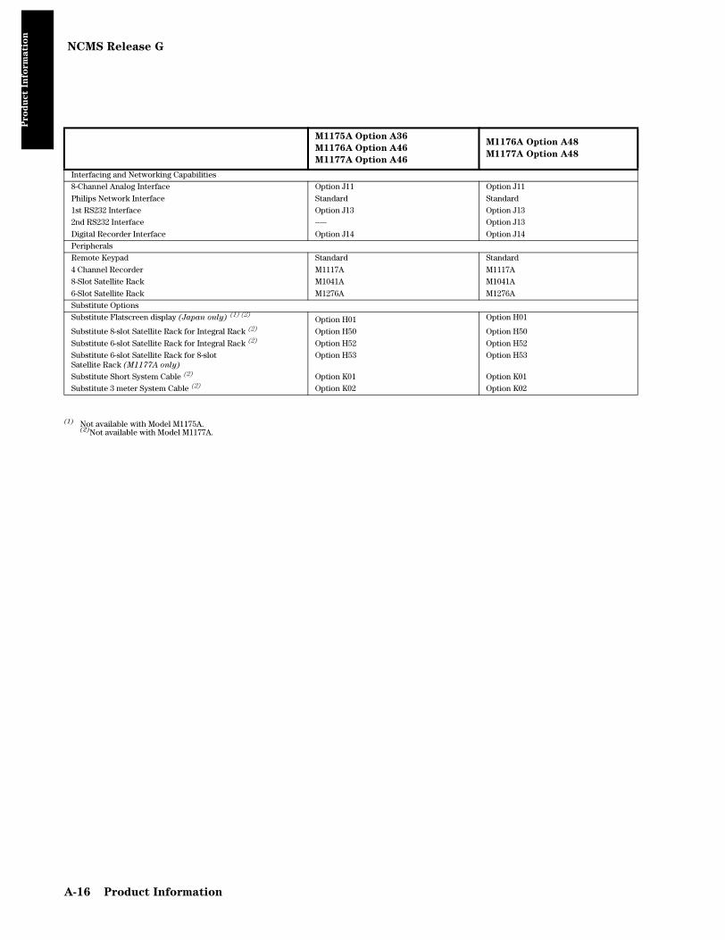
NCMS Release G
Pro
du
ct I
nfo
rm
ati
on
(1) Not available with Model M1175A.(2)Not available with Model M1177A.
Interfacing and Networking Capabilities
8-Channel Analog Interface Option J11 Option J11
Philips Network Interface Standard Standard
1st RS232 Interface Option J13 Option J13
2nd RS232 Interface ----- Option J13
Digital Recorder Interface Option J14 Option J14
Peripherals
Remote Keypad Standard Standard
4 Channel Recorder M1117A M1117A
8-Slot Satellite Rack M1041A M1041A
6-Slot Satellite Rack M1276A M1276A
Substitute Options
Substitute Flatscreen display (Japan only) (1) (2)Option H01 Option H01
Substitute 8-slot Satellite Rack for Integral Rack (2) Option H50 Option H50
Substitute 6-slot Satellite Rack for Integral Rack (2) Option H52 Option H52
Substitute 6-slot Satellite Rack for 8-slotSatellite Rack (M1177A only)
Option H53 Option H53
Substitute Short System Cable (2) Option K01 Option K01
Substitute 3 meter System Cable (2) Option K02 Option K02
M1175A Option A36
M1176A Option A46
M1177A Option A46
M1176A Option A48
M1177A Option A48
A-16 Product Information

CMS Release A.0
Pro
du
ct I
nfo
rm
ati
on
CMS Release A.0
M1175A (Mono)M1176A (Color)
M1177A (Color)
Option A56 Option A64 Option A68
Display Module
Mono / Color Mono Color Color
Number of Channels 6 4 8
Supported Remote Displays 3 3 3
Plug-in Modules
Maximum Number of Parameter Modules 8 (12 with Opt. J26) 8 12 (16 with Opt. J28)
Supported Modules
M1001A/B ECG (1) 1 1 1
M1002A/B ECG/RESP (1) 1 1 1
M1002A ECG/RESP with Analog Respiration Output (with Opt. C01)(1)(2)
1 1 1
M1006A/B Invasive Pressure 3 (5 with Opt. J26) 3 5 (6 with Opt. J28)
M1006A/B Invasive Pressure with Analog Pressure Output (with Opt. C01)
3 (5 with Opt. J26) 3 5 (6 with Opt. J28)
M1008A/B NBP (2) 1 1 1
M1012A Cardiac Output 1 1 1
M1015A Sidestream CO2 1 1 1
M1016A CO2 1 1 1
M1017A FiO2 1 1 1
M1018A tcpO2/tcpCO2 (2) 1 1 1
M1020A SpO2/Pleth 2 2 2
M1021A SvO2 (2) 1 1 1
M1022A Blood Analysis (2) 1 1 1
M1029A Temperature 2 (1 Delta Temp.) 4 (2 Delta Temp. with Opt. J26)
2 (1 Delta Temp.) 4 (2 Delta Temp.)
M1032A VueLink Type A 2 2 2
M1032A VueLink Type B 1 (2 with Opt. J26) 1 2
M1116A/B Recorder Module (2) 1 1 1
M1235A Data Transfer Module 1 1 1
Patient Data Management
Standard Data Management12 sec. resolution 1 min. resolution
StandardStandard
StandardStandard
StandardStandard
Extended Data Management
12 sec. resolution Standard with Opt. J26 — Standard with Opt. J28
1 min. resolution Standard with Opt. J26 — Standard with Opt. J28
Trends Tabular / Graphic Tabular / Graphic Tabular / Graphic
Clinical Calculations • Hemodynamic• Oxygenation• Ventilation
• Hemodynamic• Oxygenation• Ventilation
• Hemodynamic• Oxygenation• Ventilation
Neonatal Event Review Opt. C04 Opt. C04 Opt. C04
Respiratory Loops (for selected ventilators and Vuelink)
Opt. C80 Opt. C80 Opt. C80
(1) M1001A/B and M1002A/B cannot be used simultaneously in a system.(2) These modules require 2 slots in the integral and/or Satellite Rack.
Software Applications
Drug Calculator Standard Standard Standard
ST Segment Analysis Standard Standard Standard
Interfacing and Networking Capabilities
8-Channel Analog Interface Opt. J11 Opt. J11 Opt. J11
Product Information A-17

CMS Release A.0
Pro
du
ct I
nfo
rm
ati
on
Philips Network Interface Opt. J12 Opt. J12 Opt. J12
1st RS232 Interface Opt. J13 Opt. J13 Opt. J13
2nd RS232 Interface — — Opt. J13 and Opt. J28
Digital Recorder Interface Opt. J14 Opt. J14 Opt. J14
1st additional Display or Flatscreen Interface
With Opt. J26 ==>Opt. J15 (color) or Opt. J16 (mono) orOpt. J25 (Flatscreen)
— Opt. J15 (color) orOpt. J16 (mono) orOpt. J25 (Flatscreen)
Peripherals
Remote Keypad Standard Standard Standard
4 Channel Recorder M1117A M1117A M1117A
8-Slot Satellite Rack M1041A M1041A M1041A
6-Slot Satellite Rack M1276A M1276A M1276A
14 Inch Monochrome Display M1092A (Opt. A03) — M1092A (Opt. A03)
14 Inch Color Display M1094B (Opt. A03) — M1094B (Opt. A03)
10.4 Inch Flatscreen Color Display M1095A (Opt. A03) — M1095A (Opt. A03)
21 Inch Color Display(1) M1165/66A (Opt. H71) — M1165/66A (Opt. H71)
Substitute Options
Substitute Flatscreen display (Japan only) (2) (3)
Opt. H01 Opt. H01 Opt. H01
Substitute 8-slot Satellite Rack for Integral Rack (3)
Opt. H50 Opt. H50 Opt. H50
Substitute 6-slot Satellite Rack forIntegral Rack (3)
Opt. H52 Opt. H52 Opt. H52
Substitute 6-slot Satellite Rack for 8-slotSatellite Rack (M1177A only)
Opt. H53 Opt. H53 Opt. H53
Substitute 3 meter System Cable (3) Opt. K02 Opt. K02 Opt. K02
Substitute 1.5 meter System Cable (3) Opt. K03 Opt. K03 Opt. K03
(1) Includes isolation transformer.(2)Not available with Model M1175A.(3)Not available with Model M1177A.
M1175A (Mono)M1176A (Color)
M1177A (Color)
Option A56 Option A64 Option A68
A-18 Product Information

ACMS Release A.0
Pro
du
ct I
nfo
rm
ati
on
ACMS Release A.0
M1175A (Mono)M1176A (Color)
M1177A (Color)
Option A76 Option A88
Display Module
Mono / Color Mono Color
Number of Channels 6 8
Supported Remote Displays (CRT) 3 3
Plug-in Modules
Max. Number of Parameter Modules 8 (12 with Opt. J26) 12 (16 with Opt. J28)
Supported Modules
M1001A/B ECG (1) 1 1
M1002A/B ECG/RESP (1) 1 1
M1002A ECG/RESP with Analog Respiration Output (with Opt. C01) (1) (2)
1 1
M1006A/B Invasive Pressure 3 (5 with Opt. J26) 5 (6 with Opt. J28)
M1006A/B Invasive Pressure with Analog Pressure Output (with Opt. C01)
3 (5 with Opt. J26) 5 (6 with Opt. J28)
M1008A/B NBP (2) 1 1
M1012A Cardiac Output 1 1
M1015A Sidestream CO2 1 1
M1016A CO2 1 1
M1017A FiO2 1 1
M1018A tcpO2/tcpCO2 (2) 1 1
M1020A SpO2/Pleth 2 2 (1 with Opt. J28, without Opt. C11)
M1021A SvO2 (2) 1 1
M1022A Blood Analysis (2) 1 1
M1029A Temperature 2 (1Delta Temp.) 4 (2 Delta Temp.) with Opt. J26
4 (2 Delta Temp.)
M1032A VueLink Type A 2 2 (1 with Opt. C11)
M1032A VueLink Type B 2 2
M1116A/B Recorder Module (2) 1 1
M1235A Data Transfer Module 1 1
Anesthesia Gas Monitoring
M1026A Anesthetic Gas Module 1 1
Anesthesia Ventilators
Ohmeda 7800/7810 Standard Standard
Ohmeda 7900 Opt. C79 Opt. C79
Respiratory Loops (for selected ventilators &Vuelink) Opt. C80 Opt. C80
Patient Data Management
Standard Data Management12 second resolution1 min. resolution
StandardStandard
StandardStandard
Extended Data Management
12 second resolution1 min. resolution
Standard with Opt. J26 Standard with Opt. J26
Standard with Opt. J28 Standard with Opt. J28
Trends Tabular / Graphic Tabular / Graphic
Clinical Calculations • Hemodynamic• Oxygenation• Ventilation
• Hemodynamic• Oxygenation• Ventilation
(1) M1001A/B and M1002A/B cannot be used simultaneously in a system.(2) These modules require 2 slots in the integral and/or Satellite Rack.
Product Information A-19

ACMS Release A.0
Pro
du
ct I
nfo
rm
ati
on
Software Applications
Drug Calculator Standard Standard
Dual SpO2 Standard With Opt. J28 you need Opt. C11
ST Segment Analysis Standard Standard
Interfacing and Networking Capabilities
8-Channel Analog Interface (1) Standard Standard
Philips Network Interface Standard Standard
1st RS232 Dual Interface (2) Standard Standard
2nd RS232 Dual Interface Opt. J13 Opt. J13
Delete 1st RS232 Dual Interface Opt. D13 Opt. D13
Digital Recorder Interface Opt. J14 Opt. J14
1st additional independent Display or Flatscreen Interface With Opt. J26 ==>Opt. J16 (mono) or Opt. J25 (Flatscreen)
Opt. J15 (color) or Opt. J25(Flatscreen)
2nd additional independent Display or Flatscreen Interface (1)
— With Opt. J28 ==>Opt. J15 (color) orOpt. J25(Flatscreen)
Peripherals
Handheld Keypad Standard Standard
4-Channel Recorder M1117A M1117A
8-Slot Satellite Rack M1041A M1041A
6-Slot Satellite Rack M1276A M1276A
14” Monochrome Display M1092A (Opt. A03) M1092A (Opt. A03)
14”Color Display M1094B (Opt. A03) M1094B (Opt. A03)
10.4” Flatscreen Color Display M1095A (Opt. A03) M1095A (Opt. A03)
21” Color Display(3) M1165/6A (Opt. H71) M1165/6A (Opt. H71)
Substitute Options
Substitute Flatscreen display (Japan only) (4) (5) Opt. H01 Opt. H01
Substitute 8-slot Satellite Rack for Integral Rack (5) Opt. H50 Opt. H50Substitute 6-slot Satellite Rack for Integral Rack (5) Opt. H52 Opt. H52Substitute 6-slot Satellite Rack for 8-slot. Satellite Rack (M1177A
only)
Opt. H53 Opt. H53
Substitute 3 meter System Cable (5) Opt. K02 Opt. K02
Substitute 1.5 meter System Cable (5) Opt. K03 Opt. K03
(1) 2nd Independent Display Controller & an 8-channel Analog interface are not supported simultaneously.(2) Includes a 3.0 meter (9.8 ft.) RS232 cable.(3) Includes Isolation Transformer.(4) Not available with Model M1175A.(5) Not available with Model M1177A.
M1175A (Mono)M1176A (Color)
M1177A (Color)
Option A76 Option A88
A-20 Product Information

NCMS Release A.0
Pro
du
ct I
nfo
rm
ati
on
NCMS Release A.0
M1176A (Color)
M1177A (Color)
Option A48
Display Module
Color Color
Number of Channels 8
Plug-in Modules
Maximum Number of Parameter Modules 12 (16 with Opt. J28)
Supported Modules
M1001A/B ECG (1) 1
M1002A/B ECG/RESP (1) 1
M1002A ECG/RESP with Analog Respiration Output (with Opt. C01) (1) (2) 1
M1006A/B Invasive Pressure 5 (6 with Opt. J28)
M1006A/B Invasive Pressure with Analog Pressure Output (with Opt. C01) 5 (6 with Opt. J28)
M1008B NBP (2) 1
M1012A Cardiac Output 1
M1015A Sidestream CO2 1
M1016A CO2 1
M1017A FiO2 1
M1018A tcpO2/tcpCO2 (2) 1
M1020A SpO2/Pleth 2
M1021A SvO2 (2) 1
M1022A Blood Analysis (2) 1
M1029A Temperature 4 (2 Delta Temp.)
M1032A VueLink Type A 2
M1032A VueLink Type B 2
M1116A/B Recorder Module (2) 1
M1235A Data Transfer Module 1
Patient Data Management
Standard Data Management12 second resolution 1 min. resolution
StandardStandard
Extended Data Management
12 second resolution With Opt. J28
1 min. resolution With Opt. J28
Trends Tabular / Graphic
Clinical Calculations • Hemodynamic• Oxygenation• Ventilation
Neonatal Event Review Opt. C04
Respiratory Loops (for selected ventilators and Vuelink) Opt. C80
Software Applications
Drug Calculator Standard
ST Segment Analysis Standard
(1) M1001A/B and M1002A/B cannot be used simultaneously in a system.(2) These modules require 2 slots in the integral and/or Satellite Rack.
Interfacing and Networking Capabilities
8-Channel Analog Interface Opt. J11
Philips Network Interface Opt. J12
1st RS232 Interface Opt. J13
2nd RS232 Interface Opt. J13 and J28
Product Information A-21

NCMS Release A.0
Pro
du
ct I
nfo
rm
ati
on
Digital Recorder Interface Opt. J14
Interfacing and Networking Capabilities
Remote Keypad Standard
4 Channel Recorder M1117A
8-Slot Satellite Rack M1041A
6-Slot Satellite Rack M1276A
Substitute Options
Substitute Flatscreen display (Japan only) (1) Opt. H01
Substitute 8-slot Satellite Rack for Integral Rack (1) Opt. H50
Substitute 6-slot Satellite Rack for Integral Rack (1) Opt. H52
Substitute 6-slot Satellite Rack for 8-slot Satellite Rack (M1177A only)
Opt. H53
Substitute Short System Cable (1) Opt. K01
Substitute 3 meter System Cable (1) Opt. K02
Substitute 1.5 meter System Cable (1) Opt. K03
(1) Not available with Model M1177A.
M1176A (Color)
M1177A (Color)
Option A48
A-22 Product Information

CMS Release B.0
Pro
du
ct I
nfo
rm
ati
on
CMS Release B.0
M1165A / 75A (Mono)M1166A / 76A (Color)
M1167A / 77A (Color)
Option A56 Option A66 Option A68
Display Module
Mono / Color Mono Color Color
Number of Channels 6 6 8
Supported Independent Displays 1 (2 with Option J26) 1 (2 with Option J26) 2
Plug-in Modules
Maximum Number of Parameter Modules 8 (12 with Opt. J26) 8 (12 with Opt. J26) 12 (16 with Opt. J28)
Supported Modules
M1001A/B ECG (1) 1 1 1
M1002A/B ECG/RESP (1) 1 1 1
M1002A ECG/RESP with Analog Respiration Output (with Opt. C01)(1)(2) 1 1 1
M1006A/B Invasive Pressure 3 (6 with Opt. J26) 3 (6 with Opt. J26) 5 (6 with Opt. J28)
M1006A/B Invasive Pressure with Analog Pressure Output (with Opt. C01)
3 (6 with Opt. J26) 3 (6 with Opt. J26) 5 (6 with Opt. J28)
M1008A/B NBP (2) 1 1 1
M1012A Cardiac Output 1 1 1
M1015A Sidestream CO2 1 1 1
M1016A CO2 1 1 1
M1017A FiO2 1 1 1
M1018A tcpO2/tcpCO2 (2) 1 1 1
M1020A SpO2/Pleth 2 2 2
M1021A SvO2 (2) 1 1 1
M1022A Blood Analysis (2) 1 1 1
M1027A EEG (3) 1 1 1
M1029A Temperature 2 (1 Delta Temp.) 4 (2 Delta Temp. with Opt. J26)
2 (1 Delta Temp.) 4 (2 Delta Temp. with Opt. J26)
4 (2 Delta Temp.)
M1032A VueLink Type A 2 2 2
M1032A VueLink Type B 1 (2 with Opt. J26) 1 (2 with Opt. J26) 2
M1116A/B Recorder Module (2) 1 1 1
M1235A Data Transfer Module 1 1 1
Patient Data Management
Standard Data Management12 sec. resolution 1 min. resolution
StandardStandard
StandardStandard
StandardStandard
Extended Data Management
12 sec. resolution With Opt. J26 With Opt. J26 With Opt. J28
1 min. resolution With Opt. J26 With Opt. J26 With Opt. J28
Trends Tabular / Graphic Tabular / Graphic Tabular / Graphic
Clinical Calculations HemodynamicOxygenationVentilation
HemodynamicOxygenationVentilation
• Hemodynamic• Oxygenation• Ventilation
Neonatal Event Review Opt. C04 Opt. C04 —
Respiratory Loops (for selected ventilators and Vuelink)
Standard Standard Standard
(1) M1001A/B and M1002A/B cannot be used simultaneously in a system.(2) These modules require 2 slots in the integral and/or satellite rack.(3) Not yet available in the U.S. and Canada.
Software Applications
Drug Calculator Standard Standard Standard
ST Segment Analysis Standard Standard Standard
EASI™ 12-lead ECG with five electrodes Option C12 Option C12 Option C12
CSA (with M1027A EEG Module) Standard Standard Standard
Interfacing and Networking Capabilities
Product Information A-23

CMS Release B.0
Pro
du
ct I
nfo
rm
ati
on
8-Channel Analog Interface Opt. J11 Opt. J11 Opt. J11
Philips Network Interface(4) Opt. J12 Opt. J12 Opt. J12
1st RS232 Dual Interface Opt. J13 Opt. J13 Opt. J13
2nd RS232 Dual Interface Opt. J13 and Opt. J26 Opt. J13 and Opt. J26 Opt. J13 and Opt. J28
Digital Recorder Interface Opt. J14 Opt. J14 Opt. J14
1st additional independent Display or Flatscreen Interface
Requires Opt. J26 withOpt. J15 (color) or Opt. J16 (mono) orOpt. J25 (Flatscreen)
Requires Opt. J26 withOpt. J15 (color) or Opt. J16 (mono) orOpt. J25 (Flatscreen)
Opt. J15 (color) orOpt. J16 (mono) orOpt. J25 (Flatscreen) orOpt. J17 (XGA display)3
Peripherals
Handheld Keypad Standard Standard Standard
4-Channel Recorder M1117A M1117A M1117A
8-Slot Satellite Rack M1041A M1041A M1041A
6-Slot Satellite Rack M1276A M1276A M1276A
14 “ Monochrome Display M1092A (Opt. A03) M1092A (Opt. A03) M1092A (Opt. A03)
14 “ Color Display M1094B (Opt. A03) M1094B (Opt. A03) M1094B (Opt. A03)
10.4 “ Flatscreen Color Display M1095A (Opt. A03) M1095A (Opt. A03) M1095A (Opt. A03)
15 “ XGA Flatscreen Color Display (1) (3) — M1097A #A01 M1097A #A01
21 “ Color Display (1) Opt. H71 Opt. H71 Opt. H71
Substitute Options
Substitute 8-slot Satellite Rack for Integral Rack (2)
Opt. H50 Opt. H50 Opt. H50
Substitute 6-slot Satellite Rack forIntegral Rack (2)
Opt. H52 Opt. H52 Opt. H52
Substitute 6-slot Satellite Rack for 8-slotSatellite Rack (M1177A only)
Opt. H53 Opt. H53 Opt. H53
Substitute 3 meter System Cable (2) Opt. K02 Opt. K02 Opt. K02
Substitute 1.5 meter System Cable (2) Opt. K03 Opt. K03 Opt. K03
(1) Includes isolation transformer.(2) Not available with Model M1167A / 77A.(3) Only with Model M1167A / 77A.(4)) Included in standard configuration for US Models
M1165A / 75A (Mono)M1166A / 76A (Color)
M1167A / 77A (Color)
Option A56 Option A66 Option A68
A-24 Product Information

ACMS Release B.0
Pro
du
ct I
nfo
rm
ati
on
ACMS Release B.0
M1165A / 75A (Mono)M1166A / 76A (Color)
M1167A / 77A (Color)
Option A76 Option A86 Option A88
Display Module
Mono / Color Mono Color Color
Number of Channels 6 6 8
Supported Independent Displays 1 (2 with Option J26) 1 (2 with Opt. J26) 2 (3 with Opt. J28)
Plug-in Modules
Max. Number of Parameter Modules 8 (12 with Opt. J26) 8 (12 with Opt. J26) 12 (16 with Opt. J28)
Supported Modules
M1001A/B ECG (1) 1 1 1
M1002A/B ECG/RESP (1) 1 1 1
M1002A ECG/RESP with Analog Respiration Output (with Opt. C01) (1) (2)
1 1 1
M1006A/B Invasive Pressure 3 (6 with Opt. J26) 3 (6 with Opt. J26) 5 (6 with Opt. J28)
M1006A/B Invasive Pressure with Analog Pressure Output (with Opt. C01)
3 (6 with Opt. J26) 3 (6 with Opt. J26) 5 (6 with Opt. J28)
M1008A/B NBP (2) 1 1 1
M1012A Cardiac Output 1 1 1
M1015A Sidestream CO2 (2) 1 1 1
M1016A CO2 1 1 1
M1017A FiO2 1 1 1
M1018A tcpO2/tcpCO2 (2) 1 1 1
M1020A SpO2/Pleth 2 2 2
M1021A SvO2 (2) 1 1 1
M1022A Blood Analysis (2) 1 1 1
M1027A EEG (3) 1 1 1
M1029A Temperature 2 (1 Delta Temp.) 4 (2 Delta Temp.) with Opt. J26
2 (1 Delta Temp.) 4 (2 Delta Temp.) with Opt. J26
4 (2 Delta Temp.)
M1032A VueLink Type A 2 2 2
M1032A VueLink Type B 1 (2 with Opt. J26) 1 (2 with Opt. J26) 2
M1116A/B Recorder Module (2) 1 1 1
M1235A Data Transfer Module 1 1 1
Anesthesia Gas Monitoring
M1026A Anesthetic Gas Module 1 1 1
Anesthesia VentilatorsOhmeda 7800/7810 Standard Standard Standard
Ohmeda 7900 Opt. C79 Opt. C79 Opt. C79
Respiratory Loops (for selected ventilators &Vuelink) Standard Standard Standard
Patient Data Management
Standard Data Management 12 second resolution1 min. resolution
StandardStandard
StandardStandard
StandardStandard
Extended Data Management12 second resolution1 min. resolution
With Opt. J26 With Opt. J26
With Opt. J26 With Opt. J26
With Opt. J28 With Opt. J28
Trends Tabular / Graphic Tabular / Graphic Tabular / Graphic
Clinical Calculations • Hemodynamic• Oxygenation• Ventilation
• Hemodynamic• Oxygenation• Ventilation
• Hemodynamic• Oxygenation• Ventilation
(1) M1001A/B and M1002A/B cannot be used simultaneously in a system.(2) These modules require 2 slots in the integral and/or satellite rack.(3) Not yet available in the U.S. and Canada.
Product Information A-25

ACMS Release B.0
Pro
du
ct I
nfo
rm
ati
on
Software Applications
Drug Calculator Standard Standard Standard
Dual SpO2 Standard Standard Standard
ST Segment Analysis Standard Standard Standard
EASI™ 12-lead ECG with five electrodes Option C12 Option C12 Option C12
CSA (with M1027A EEG Module) Standard Standard Standard
Interfacing and Networking Capabilities
8-Channel Analog Interface (1) Opt. J11 Opt. J11 Opt. J11
Philips Network Interface (2) Opt. J12 Opt. J12 Opt. J12
1st RS-232 Dual Interface (3) Standard Standard Standard
2nd RS-232 Dual Interface Opt. J13 Opt. J13 Opt. J13
Delete 1st RS-232 Dual Interface Opt. D13 Opt. D13 Opt. D13
Digital Recorder Interface Opt. J14 Opt. J14 Opt. J14
1st additional independent Display or Flatscreen Interface Requires Opt. J26 with Opt. J16 (mono)
Opt. J15 (color) or Opt. J25 (Flatscreen) or Opt. J17 (XGA display) (6)
Opt. J15 (color) or Opt. J25 (Flatscreen) or Opt. J17 (XGA display) (6)
2nd additional independent Display or Flatscreen Inter-face(1)
— Requires Opt. J28 with Opt. J15 (color) orOpt. J25 (Flatscreen) or Opt. J17 (XGA display) (6)
Requires Opt. J28 with Opt. J15 (color) orOpt. J25 (Flatscreen) or Opt. J17 (XGA display) (6)
Peripherals
Handheld Keypad Standard Standard Standard
4-Channel Recorder M1117A M1117A M1117A
8-Slot Satellite Rack M1041A M1041A M1041A
6-Slot Satellite Rack M1276A M1276A M1276A
14” Monochrome Display M1092A (Opt. A03) M1092A (Opt. A03) M1092A (Opt. A03)
14” Color Display — M1094B (Opt. A03) M1094B (Opt. A03)
10.4” Flatscreen Color Display — M1095A (Opt. A03) M1095A (Opt. A03)
15” XGA Flatscreen Color Display (4) (6) — M1097A(6) M1097A(6)
21” Color Display (4) Opt. H71 Opt. H71 Opt. H71
Substitute Options
Substitute 8-slot Satellite Rack for Integral Rack (5) Opt. H50 Opt. H50 Opt. H50Substitute 6-slot Satellite Rack for Integral Rack (5) Opt. H52 Opt. H52 Opt. H52Substitute 6-slot Satellite Rack for 8-slot Satellite Rack (M1167A / 77A only)
Opt. H53 Opt. H53 Opt. H53
Substitute 3 meter System Cable (5) Opt. K02 Opt. K02 Opt. K02
Substitute 1.5 meter System Cable (5) Opt. K03 Opt. K03 Opt. K03
(1) 2nd additional Independent Display Controller & an 8-channel Analog interface are not supported simultaneously.(2) Standard in USA.(3) Includes a 3.0 meter (9.8 ft.) RS-232 cable.(4) Includes Isolation Transformer.(5) Not available with Model M1167A / 77A.(6) Only with Model M1167A / 77A.
M1165A / 75A (Mono)M1166A / 76A (Color)
M1167A / 77A (Color)
Option A76 Option A86 Option A88
A-26 Product Information

NCMS Release B.0
Pro
du
ct I
nfo
rm
ati
on
NCMS Release B.0
M1166A, M1167A, M1176A, M1177A
Option A48
Display Module
Color Color
Number of Channels 8
Supported Independent Displays 2
Plug-in Modules
Maximum Number of Parameter Modules 12 (16 with Opt. J28)
Supported Modules
M1001A/B ECG (1) 1
M1002A/B ECG/RESP (1) 1
M1002A ECG/RESP with Analog Respiration Output (with Opt. C01) (1) (2) 1
M1006A/B Invasive Pressure 5 (6 with Opt. J28)
M1006A/B Invasive Pressure with Analog Pressure Output (with Opt. C01) 5 (6 with Opt. J28)
M1008B NBP (2) 1
M1012A Cardiac Output 1
M1015A Sidestream CO2 1
M1016A CO2 1
M1017A FiO2 1
M1018A tcpO2/tcpCO2 (2) 1
M1020A SpO2/Pleth 2
M1021A SvO2 (2) 1
M1022A Blood Analysis (2) 1
M1027A EEG 1
M1029A Temperature 4 (2 Delta Temp.)
M1032A VueLink Type A 2
M1032A VueLink Type B 2
M1116A/B Recorder Module (2) (3) 1
M1235A Data Transfer Module 1
Patient Data Management
Standard Data Management12 second resolution 1 min. resolution
StandardStandard
Extended Data Management
12 second resolution With Opt. J28
1 min. resolution With Opt. J28
Trends Tabular / Graphic
Clinical Calculations • Hemodynamic• Oxygenation• Ventilation
Neonatal Event Review Opt. C04
Respiratory Loops (for selected ventilators and Vuelink) Standard
Software Applications
Drug Calculator Standard
ST Segment Analysis Standard
CSA (with M1027A EEG Module) Standard
(1) M1001A/B and M1002A/B cannot be used simultaneously in a system.(2) These modules require 2 slots in the integral and/or satellite rack.(3) M1116A does not support recording of continuous oxyCRG or oxyCRG episodes.
Interfacing and Networking Capabilities
Product Information A-27

NCMS Release B.0
Pro
du
ct I
nfo
rm
ati
on
8-Channel Analog Interface Opt. J11
Philips Network Interface Opt. J12
1st RS232 Dual Interface Opt. J13
2nd RS232 Dual Interface Opt. J13 and J28
Digital Recorder Interface Opt. J14
Additional Independent Display Interface Opt. J15 (color CRT) orOpt. J25 (Flatscreen) orOpt. J17 (XGA display)
Peripherals
Handheld Keypad Standard
4-Channel Recorder M1117A
8-Slot Satellite Rack M1041A
6-Slot Satellite Rack M1276A
14 Inch Color Display M1094B (Opt. A03)
10.4 Inch Flatscreen Color Display M1095A (Opt. A03)
14 Inch XGA Flatscreen Color Display (2) (3) M1097A
21 Inch Color Display (2) Opt. H71
Substitute Options
Substitute 8-slot Satellite Rack for Integral Rack (1) Opt. H50
Substitute 6-slot Satellite Rack for Integral Rack (1) Opt. H52
Substitute 6-slot Satellite Rack for 8-slot Satellite Rack (M1167A / 77A only) Opt. H53
Substitute Short System Cable (1) Opt. K01
Substitute 3 meter System Cable (1) Opt. K02
Substitute 1.5 meter System Cable (1) Opt. K03
(1) Not available with Model M1167A / 77A.(2) Includes isolation transformer.(3) Only with Model M1167A / 77A.
M1166A, M1167A, M1176A, M1177A
Option A48
A-28 Product Information

CMS Release C.0
Pro
du
ct I
nfo
rm
ati
on
CMS Release C.0
M1165A / 75A
(Mono)
M1166A (Color)
M1167A (Color)
M1166A / 76A (Color)
M1167A / 77A (Color)
Option A56 Option A64 Option A66 Option A68
Display Module
Mono / Color Mono Color Color Color
Number of Channels 6 4 6 8
Supported Independent Displays 1 (2 with Option J26) 1 1 (2 with Option J26) 2
Plug-in Modules
Maximum Number of Parameter Modules 8 (12 with Opt. J26) 8 8 (12 with Opt. J26) 12 (16 with Opt. J28)
Supported Modules
M1001A/B ECG (1) 1 1 1 1
M1002A/B ECG/RESP (1) 1 1 1 1
M1002A ECG/RESP with Analog Respiration Output (with Opt. C01)(1)(2) 1 1 1 1
M1006A/B Invasive Pressure without or
with Analog Pressure Output (Opt.C01)3 (6 with Opt. J26 (3)) 3 3 (6 with Opt. J26 (3)) 5 (6 with Opt. J28 (3))
M1008A/B NBP (2) 1 1 1 1
M1012A Cardiac Output without or with Option C10
1 1 1 1
M1015A Sidestream CO2(2)(4) 1 1 1 1
M1016A CO2 1 1 1 1
M1017A FiO2 1 1 1 1
M1018A tcpO2/tcpCO2 (2) 1 1 1 1
M1020A SpO2/Pleth 2 2 2 2
M1021A SvO2 (2) 1 1 1 1
M1022A Blood Analysis (2) 1 1 1 1
M1027A EEG 1 1 1 1
M1029A Temperature 2 (1 Delta Temp.) 4 (2 Delta Temp. with Opt. J26)
2 (1 Delta Temp.) 2 (1 Delta Temp.) 4 (2 Delta Temp. with Opt. J26)
4 (2 Delta Temp.)
M1032A VueLink Type A 2 2 2 2
M1032A VueLink Type B 2 (3 with Opt. J26 and C32 (3))
2 2 (3 with Opt. J26 and C32 (3))
2 (3 with Opt. J28 and C32 (3))
M1034A BIS 1 1 1 1
M1116A/B Recorder Module (2) 1 1 1 1
M1235A Data Transfer Module 1 1 1 1
Patient Data Management
Standard Data Management Standard Standard Standard Standard
Extended Data Management Standard with Opt. J26 --- Standard with Opt. J26 Standard with Opt. J28
Trends Tabular / Graphic Tabular / Graphic Tabular / Graphic Tabular / Graphic
Clinical Calculations • Hemodynamic• Oxygenation• Ventilation
• Hemodynamic• Oxygenation• Ventilation
• Hemodynamic• Oxygenation• Ventilation
• Hemodynamic• Oxygenation• Ventilation
Neonatal Event Review Opt. C04 Opt. C04 Opt. C04 Opt. C04
Respiratory Loops (for selected ventilators and Vuelink)
Standard Standard Standard Standard
(1) M1001A/B and M1002A/B cannot be used simultaneously in a system.(2) These modules require 2 slots in the integral and/or satellite rack.(3) Only 5 M1006A/B Invasive Pressure modules are supported if 3 Vuelink Type B modules are used.(4) Requires CO2 Module
Product Information A-29

CMS Release C.0
Pro
du
ct I
nfo
rm
ati
on
Software Applications
Drug Calculator Standard Standard Standard Standard
Dual SpO2 Standard Standard Standard Standard
ST Segment Analysis Standard Standard Standard Standard
EASI™ 12-lead ECG with five electrodes Standard Standard Standard Standard
CSA (with M1027A EEG Module) Standard Standard Standard Standard
Interfacing and Networking Capabilities
8-Channel Analog Interface Opt. J11 Opt. J11 Opt. J11 Opt. J11
Philips Network Interface(4) Opt. J12 Opt. J12 Opt. J12 Opt. J12
1st RS232 Dual Interface Opt. J13 Opt. J13 Opt. J13 Opt. J13
2nd RS232 Dual Interface(5) Opt. J13 Opt. J13 Opt. J13 Opt. J13
Digital Recorder Interface Opt. J14 Opt. J14 Opt. J14 Opt. J14
1st additional independent Display or Flatscreen Interface
Requires Opt. J26 withOpt. J16 (mono)
Requires Opt. J26 withOpt. J15 (color) or Opt. J16 (mono) orOpt. J17 (XGA display) orOpt. J25 (Flatscreen)
Opt. J15 (color) orOpt. J16 (mono) orOpt. J25 (Flatscreen) orOpt. J17 (XGA dis-play)3
Peripherals
Handheld Keypad Standard Standard Standard Standard
4-Channel Recorder M1117A M1117A M1117A M1117A
8-Slot Satellite Rack M1041A M1041A M1041A M1041A
6-Slot Satellite Rack M1276A M1276A M1276A M1276A
14 “ Monochrome Display M1092A (Opt. A03) M1092A (Opt. A03) M1092A (Opt. A03) M1092A (Opt. A03)
14 “ Color Display M1094B (Opt. A03) M1094B (Opt. A03) M1094B (Opt. A03) M1094B (Opt. A03)
10.4 “ Flatscreen Color Display M1095A (Opt. A03) M1095A (Opt. A03) M1095A (Opt. A03) M1095A (Opt. A03)
15 “ XGA Touchscreen Color Display (1) (3) — M1097A #A02 M1097A #A02 M1097A #A02
21 “ Color Display (1) Opt. H71 Opt. H71 Opt. H71 Opt. H71
Substitute Options
Substitute 8-slot Satellite Rack for Integral Rack (2)
Opt. H50 Opt. H50 Opt. H50 Opt. H50
Substitute 6-slot Satellite Rack forIntegral Rack (2)
Opt. H52 Opt. H52 Opt. H52 Opt. H52
Substitute 6-slot Satellite Rack for 8-slotSatellite Rack (M1177A only)
Opt. H53 Opt. H53 Opt. H53 Opt. H53
Substitute 3 meter System Cable (2) Opt. K02 Opt. K02 Opt. K02 Opt. K02
Substitute 1.5 meter System Cable (2) Opt. K03 Opt. K03 Opt. K03 Opt. K03
(1) Includes isolation transformer.(2) Not available with Model M1167A / 77A.(3) Touchscreen operation available only when used as main display with models M1167A/77A.(4) Included in standard configuration for US Models.(5) For M1167A/77A, 2nd RS232 Interface is not available with Option H05.
M1165A / 75A
(Mono)
M1166A (Color)
M1167A (Color)
M1166A / 76A (Color)
M1167A / 77A (Color)
Option A56 Option A64 Option A66 Option A68
A-30 Product Information

ACMS Release C.0
Pro
du
ct I
nfo
rm
ati
on
ACMS Release C.0
M1165A / 75A
(Mono)
M1166A (Color)
M1167A (Color)
M1166A / 76A (Color)
M1167A / 77A (Color)
Option A76 Option A84 Option A86 Option A88
Display Module
Mono / Color Mono Color Color Color
Number of Channels 6 4 6 8
Supported Independent Displays 1 (2 with Opt. J26) 1 1 (2 with Opt. J26) 2 (3 with Opt. J28)
Plug-in Modules
Max. Number of Parameter Modules 8 (12 with Opt. J26) 8 8 (12 with Opt. J26) 12 (16 with Opt. J28)
Supported Modules
M1001A/B ECG (1) 1 1 1 1
M1002A/B ECG/RESP (1) 1 1 1 1
M1002A ECG/RESP with Analog Respiration Output (with Opt. C01) (1) (2)
1 1 1 1
M1006A/B Invasive Pressure without or
with Analog Pressure Output (Opt.C01)3 (6 with Opt. J26 (4)) 3 3 (6 with Opt. J26(4)) 5 (6 with Opt. J28(4))
M1008A/B NBP (2) 1 1 1 1
M1012A Cardiac Output without or with Option C10
1 1 1 1
M1015A Sidestream CO2 (2) (3) 1 1 1 1
M1016A CO2 1 1 1 1
M1017A FiO2 1 1 1 1
M1018A tcpO2/tcpCO2 (2) 1 1 1 1
M1020A SpO2/Pleth 2 2 2 2
M1021A SvO2 (2) 1 1 1 1
M1022A Blood Analysis (2) 1 1 1 1
M1027A EEG 1 1 1 1
M1029A Temperature 2 (1 Delta Temp.) 4 (2 Delta Temp.) with Opt. J26
2 (1 Delta Temp.) 2 (1 Delta Temp.) 4 (2 Delta Temp.) with Opt. J26
4 (2 Delta Temp.)
M1032A VueLink Type A 2 2 2 2
M1032A VueLink Type B 2 (3 with Opt. J26 and C32 (4))
2 2 (3 with Opt. J26 and C32(4))
2 (3 with Opt. J28 and C32(4))
M1034A BIS 1 1 1 1
M1116A/B Recorder Module (2) 1 1 1 1
M1235A Data Transfer Module 1 1 1 1
Anesthesia Gas Monitoring
M1026A Anesthetic Gas Module 1 1 1 1
Anesthesia VentilatorsOhmeda 7800/7810 Standard Standard Standard Standard
Ohmeda 7900 Opt. C79 Opt. C79 Opt. C79 Opt. C79
Respiratory Loops (selected ventilators &Vuelink) Standard Standard Standard Standard
Patient Data Management
Standard Data Management Standard Standard Standard Standard
Extended Data Management With Opt. J26 --- With Opt. J26 With Opt. J28
Trends Tabular / Graphic Tabular / Graphic Tabular / Graphic Tabular/Graphic
Clinical Calculations • Hemodynamic• Oxygenation• Ventilation
• Hemodynamic• Oxygenation• Ventilation
• Hemodynamic• Oxygenation• Ventilation
• Hemodynamic• Oxygenation• Ventilation
(1) M1001A/B and M1002A/B cannot be used simultaneously in a system.(2) These modules require 2 slots in the integral and/or satellite rack.(3) Requires CO2 Module(4) Only 5 M1006A/B Invasive Pressure modules are supported if 3 Vuelink Type B modules are used.
Product Information A-31

ACMS Release C.0
Pro
du
ct I
nfo
rm
ati
on
Software Applications
Drug Calculator Standard Standard Standard Standard
Dual SpO2 Standard Standard Standard Standard
ST Segment Analysis Standard Standard Standard Standard
EASI™ 12-lead ECG with five electrodes Standard Standard Standard Standard
CSA (with M1027A EEG Module) Standard Standard Standard Standard
Interfacing and Networking Capabilities
8-Channel Analog Interface (1) Opt. J11 Opt. J11 Opt. J11 Opt. J11
Philips Network Interface (2) Opt. J12 Opt. J12 Opt. J12 Opt. J12
1st RS-232 Dual Interface (3) Standard Standard Standard Standard
2nd RS-232 Dual Interface (4) Opt. J13 Opt. J13 Opt. J13 Opt. J13
Delete 1st RS-232 Dual Interface Opt. D13 Opt. D13 Opt. D13 Opt. D13
Digital Recorder Interface Opt. J14 Opt. J14 Opt. J14 Opt. J14
1st additional independent Display or Flatscreen Inter-face
Requires Opt. J26 with Opt. J16 (mono)
Opt. J15 (color) or Opt. J16 (mono)Opt. J25 (Flatscreen) or Opt. J17 (XGA display) (6)
Opt. J15 (color) or Opt. J16 (mono) or Opt. J25 (Flat) or Opt. J17 (XGA) (6)
2nd additional independent Display or Flatscreen Inter-face(1)
— — — Requires Opt. J28 with Opt. J15 (color) orOpt. J25 (Flat) or Opt. J17 (XGA) (6)
Peripherals
Handheld Keypad Standard Standard Standard Standard
4-Channel Recorder M1117A M1117A M1117A M1117A
8-Slot Satellite Rack M1041A M1041A M1041A M1041A
6-Slot Satellite Rack M1276A M1276A M1276A M1276A
14” Monochrome Display M1092A (Opt. A03) M1092A (Opt. A03) M1092A (Opt. A03) M1092A (Opt. A03)
14” Color Display — M1094B (Opt. A03) M1094B (Opt. A03) M1094B (Opt. A03)
10.4” Flatscreen Color Display — M1095A (Opt. A03) M1095A (Opt. A03) M1095A (Opt. A03)
15” XGA Touchscreen Color Display (5) (6) — M1097A # A02(6) M1097A # A02(6) M1097A # A02(6)
21” Color Display (5) Opt. H71 Opt. H71 Opt. H71 Opt. H71
Substitute Options
Substitute 8-slot Satellite Rack for Integral Rack (7) Opt. H50 Opt. H50 Opt. H50 Opt. H50Substitute 6-slot Satellite Rack for Integral Rack (7) Opt. H52 Opt. H52 Opt. H52 Opt. H52Substitute 6-slot Satellite Rack for 8-slot Satellite Rack (M1167A / 77A only)
Opt. H53 Opt. H53 Opt. H53 Opt. H53
Substitute 3 meter System Cable (7) Opt. K02 Opt. K02 Opt. K02 Opt. K02
Substitute 1.5 meter System Cable (7) Opt. K03 Opt. K03 Opt. K03 Opt. K03
(1) 2nd additional Independent Display Controller & an 8-channel Analog interface are not supported simultaneously.(2) Standard in USA.(3) Includes a 3.0 meter (9.8 ft.) RS-232 cable.(4) For M1167A/77A, 2nd RS232 Interface is not available with Option H05.(5) Includes Isolation Transformer.(6) Touchscreen operation available only when used as main display with models M1167A/77A.(7) Not available with Model M1167A / 77A.
M1165A / 75A
(Mono)
M1166A (Color)
M1167A (Color)
M1166A / 76A (Color)
M1167A / 77A (Color)
Option A76 Option A84 Option A86 Option A88
A-32 Product Information

NCMS Release C.0
Pro
du
ct I
nfo
rm
ati
on
NCMS Release C.0
M1166A (Color)
M1167A (Color)
M1166A, M1167A, M1176A,
M1177A
Option A44 Option A48
Display Module
Color Color Color
Number of Channels 4 8
Supported Independent Displays 1 2
Plug-in Modules
Maximum Number of Parameter Modules 8 12 (16 with Opt. J28)
Supported Modules
M1001A/B ECG (1) 1 1
M1002A/B ECG/RESP (1) 1 1
M1002A ECG/RESP with Analog Respiration Output (with Opt. C01) (1) (2)
1 1
M1006A/B Invasive Pressure without or with Analog Pressure Output (Opt.C01)
3 5 (6 with Opt. J28 (5))
M1008B NBP (2) 1 1
M1012A Cardiac Output without or with Option C10 1 1
M1015A Sidestream CO2 (2) (3) 1 1
M1016A CO2 1 1
M1017A FiO2 1 1
M1018A tcpO2/tcpCO2 (2) 1 1
M1020A SpO2/Pleth 2 2
M1021A SvO2 (2) 1 1
M1022A Blood Analysis (2) 1 1
M1027A EEG 1 1
M1029A Temperature 2 (1 Delta Temp.) 4 (2 Delta Temp.)
M1032A VueLink Type A 2 2
M1032A VueLink Type B 2 2 (3 with Opt. J28 and C32(5))
M1034A BIS 1 1
M1116A/B Recorder Module (2) (4) 1 1
M1235A Data Transfer Module 1 1
Patient Data Management
Standard Data Management 12 second resolution1 min. resolution
StandardStandard
StandardStandard
Extended Data Management 12 second resolution --- With Opt. J28
1 min. resolution --- With Opt. J28
Trends Tabular / Graphic Tabular / Graphic
Clinical Calculations • Hemodynamic• Oxygenation• Ventilation
• Hemodynamic• Oxygenation• Ventilation
Neonatal Event Review Opt. C04 Opt. C04
Respiratory Loops (for selected ventilators and Vuelink) Standard Standard
Software Applications
Drug Calculator Standard Standard
Dual SpO2 Standard Standard
ST Segment Analysis Standard Standard
CSA (with M1027A EEG Module) Standard Standard
(1) M1001A/B and M1002A/B cannot be used simultaneously in a system.
(2) These modules require 2 slots in the integral and/or satellite rack.(3) Requires CO2 Module(4) M1116A does not support recording of continuous oxyCRG or
oxyCRG episodes.(5) Only 5 M1006A/B Invasive Pressure modules are supported if 3
Vuelink Type B modules are used.
Product Information A-33

NCMS Release C.0
Pro
du
ct I
nfo
rm
ati
on
Interfacing and Networking Capabilities
8-Channel Analog Interface Opt. J11 Opt. J11
Philips Network Interface(1) Opt. J12 Opt. J12
1st RS232 Dual Interface Opt. J13 Opt. J13
2nd RS232 Dual Interface(2) Opt. J13 Opt. J13
Digital Recorder Interface Opt. J14 Opt. J14
Additional Independent Display Interface Opt. J15 (color CRT) orOpt. J25 (Flatscreen) orOpt. J17 (XGA display)
Peripherals
Handheld Keypad Standard Standard
4-Channel Recorder M1117A M1117A
8-Slot Satellite Rack M1041A M1041A
6-Slot Satellite Rack M1276A M1276A
14 Inch Color Display M1094B (Opt. A03) M1094B (Opt. A03)
10.4 Inch Flatscreen Color Display M1095A (Opt. A03) M1095A (Opt. A03)
15” XGA Touchscreen Color Display (3) (4) M1097A #A02 M1097A #A02
21 Inch Color Display (3) Opt. H71 Opt. H71
Substitute Options
Substitute 8-slot Satellite Rack for Integral Rack (5) Opt. H50 Opt. H50
Substitute 6-slot Satellite Rack for Integral Rack (5) Opt. H52 Opt. H52
Substitute 6-slot Satellite Rack for 8-slot Satellite Rack (M1167A / 77A
only)
Opt. H53 Opt. H53
Substitute Short System Cable (5) Opt. K01 Opt. K01
Substitute 3 meter System Cable (5) Opt. K02 Opt. K02
Substitute 1.5 meter System Cable (5) Opt. K03 Opt. K03
(1) Included in standard configuration for US Models.
(2) For M1167A/77A, 2nd RS232 Interface is not available with Option H05.(3) Includes isolation transformer.(4) Touchscreen operation available only when used as main display with models M1167A/77A.
(5) Not available with Model M1167A / 77A.
M1166A (Color)
M1167A (Color)
M1166A, M1167A, M1176A,
M1177A
Option A44 Option A48
A-34 Product Information

Tables
Appendix B Conversion Charts
Co
nversio
n C
harts
TablesTable B-1 Common Conversions
Measure Metric Conversion English Conversions
Length 1 meter = 3.28 feet1 centimeter = 0.39 inches1 millimeter = 0.04 inches
1 foot = 0.305 meters1 inch = 2.54 centimeters1 inch = 25.40 millimeters
Mass and Weight 1 kg = 2.21 lbs1 gram = 0.35 ounces
1 lb. = 0.45 kgs1 ounce = 28.35 grams
Volume 1 liter = 0.26 gallons1 liter = 2.12 pints
1 gallon = 3.79 liters1 pint = 0.47 liters
Pressure 1 mmHg = 0.15 kPa 1 kPa = 6.67 mmHg
Temperature F = 1.8*oC + 32o C = 0.56* (oF - 32o)
Table B-2 Weight Conversions
English Metric English Metric
100 lbs 45 kgs 170 lbs 77 kgs
105 lbs 47 kgs 175 lbs 80 kgs
110 lbs 50 kgs 180 lbs 82 kgs
115 lbs 52 kgs 185 lbs 84 kgs
120 lbs 55 kgs 190 lbs 86 kgs
125 lbs 57 kgs 195 lbs 88 kgs
130 lbs 59 kgs 200 lbs 90 kgs
135 lbs 61 kgs 205 lbs 92 kgs
140 lbs 64 kgs 210 lbs 95 kgs
145 lbs 66 kgs 215 lbs 97 kgs
150 lbs 68 kgs 220 lbs 99 kgs
155 lbs 70 kgs 225 lbs 101 kgs
160 lbs 73 kgs 230 lbs 104 kgs
165 lbs 74 kgs 235 lbs 106 kgs
Table B-3 Length Conversions
English Metric English Metric
4’ 5” 135 cm 5’ 7” 170 cm
4’ 6” 137 cm 5’ 8” 173 cm
4’ 7” 140 cm 5’ 9” 175 cm
4’ 8” 142 cm 5’ 10” 178 cm
4’ 9” 145 cm 5’ 11” 180 cm
4’ 10” 147 cm 6’ 183 cm
4’ 11” 150 cm 6’ 1” 185 cm
5’ 152 cm 6’ 2” 188 cm
5’ 1” 155 cm 6’ 3” 191 cm
5’ 2” 157 cm 6’ 4” 193 cm
5’ 3” 160 cm 6’ 5” 196 cm
5’ 4” 163 cm 6’ 6’ 198 cm
5’ 5” 165 cm 6’ 7” 201 cm
5’ 6” 168 cm 6’ 8” 203 cm
Conversion Charts B-1

Tables
Co
nversio
n C
harts
Table B-4 Altitude Switch Settings
SW Set Alt (Meters) Alt (Feet) Bar Press/mmHg
00 0-50 0-164 760-75601 51-150 165-492 755-74702 151-250 493-820 746-72903 251-350 821-1148 736-72904 351-450 1149-1475 728-72005 451-550 1476-1803 719-71206 551-650 1804-2131 711-70307 651-750 2132-2459 702-69408 751-850 2460-2787 693-6859 851-950 2788-3115 694-67710 951-1050 3116-3443 676-66911 1051-1150 3444-3771 668-66012 1151-1250 3772-4098 659-65313 1251-1350 4099-4426 652-64414 1351-1450 4427-4754 643-63615 1451-1550 4755-5082 635-62816 1551-1650 5083-5410 627-61917 1651-1750 5411-5738 619-61218 1751-1850 5739-6066 611-60519 1851-1950 6067-6395 604-59720 1950-2050 6396-6723 596-59021 2051-2150 6724-7051 589-58022 2151-2250 7052-7378 579-57423 2251-2350 7379-7706 573-56724 2351-2450 7707-8034 566-55925 2451-2550 8035-8364 558-55326 2551-2650 8365-8690 552-54527 2651-2750 8691-9018 544-53728 2751-2850 9019-9846 536-53029 2851-2950 9347-9673 529-52330 2951-3050 9674-10000 522-51631 3051-3150 10001-10328 515-50932 3151-3250 10329-10656 508-50333 3251-3350 10627-10984 502-49634 3351-3450 10985-11311 495-48935 3451-3550 11312-11639 488-48336 3551-3650 11640-11967 482-47637 3651-3750 11968-12295 475-47038 3751-3850 12296-12623 469-46339 3851-3950 12624-12951 462-45640 3951-4050 12952-13279 455-45041 4051-4150 13280-13607 449-44442 4151-4250 13608-13934 443-43843 4251-4350 13935-14262 437-43244 4351-4450 14263-14590 431-42645 4451-4550 14591-14918 425-42046 4551-4650 14919-15246 419-41447 4651-4750 15247-15574 413-40848 4750-4850 15575-15904 407-40349 4851-4950 15905-16066 402-399
B-2 Conversion Charts

Appendix C Philips 15210B Calibration Unit
Ph
ilip
s 1
52
10
B
Cali
bratio
nU
nit
Installation
Description
The Philips 15210B Calibration Unit consists of a gas cylinder connected to a gas outlet via a time controlled valve. The valve is normally closed, ensuring that no gas is lost when the unit is not in use. When the unit is set up for use and the timer control knob is turned, gas is directed to the calibration chamber on the tcpO2/tcpCO2 module (Philips M1018A) for a period of up to 20 minutes. After this time the valve automatically closes.
This section provides the necessary information for you to install and service the Philips 15210B.
Unpacking the Instrument
If external damage to the shipping carton is evident, ask the carrier’s agent to be present when the unit is unpacked.
Initial Inspection
Check the instrument for any external damage such as dents and scratches on panel surfaces. If the shipping carton is not damaged, check the cushioning material and note any signs of severe stress as an indication of rough handling in transit. Retain the packaging material for possible repacking.
Claims for Damage
If physical damage is evident when the Calibration Unit is received or the unit does not meet the specified operational requirements, please notify the carrier and the nearest Philips Sales/Service office immediately. The Sales/Service office will arrange for repair or replacement without waiting for settlement of the claim against the carrier.
Calmod.tif
Philips 15210B Calibration Unit C-1

Installation
Ph
ilip
s 1
52
10
B
Cali
bratio
nU
nit
Repacking for Shipment or Storage
If the Calibration Unit is to be shipped to a Philips Sales/Service office, securely attach a tag showing the name and address of the owner, the model and serial number, and the repair required or symptoms of the fault. If available and reusable, the original shipping carton and packaging material should be used to provide adequate protection during shipping. The Philips Sales/Service office will provide information and recommendations on materials to be used if the original material is not available or reusable.
Instrument Identification
Philips uses a nine character sequence for instrument identification. The serial number is located on a plate attached to the rear panel of the instrument.
Specification
NOTE The 15210B is intended for use with Philips “CAL 1” gas cylinders (part number 15210-60010 or 15210-64010 for Europe and Japan).
Gas Supply: 1 low pressure cylinder.
Gas Flow: 8 ml +4/-2 ml per minute for 15210-64010,12 ml +4/-2 ml per minute for 15210-60010.
Cylinder Pressure: Indicated by an integral pressure manometer.
Timer Period: 20 minutes.
Dimensions: 90mm (35.4in) high x 220mm (86.6in) wide x 235mm (92.5in) deep, (without cylinder).
Weight: 2.4 kg (5.3lbs), (without cylinder).
C-2 Philips 15210B Calibration Unit

Installation
Ph
ilip
s 1
52
10
B
Cali
bratio
nU
nit
Operating Environment
The environment where the Philips 15210B will be used should be reasonably free from vibration, dust, corrosive or explosive gases, extremes of temperature, humidity, etc. The Philips 15210B operates within specifications at ambient temperatures between 0°C and 55°C. The maximum operating relative humidity is 95% at 40°C. Ambient temperatures or humidities which exceed these limits could affect the accuracy of the calibration unit and cause damage to components.
Operating Information
Each Philips 15210B is delivered with a multilanguage collection of stick-on operating labels. Each label summarizes day-to-day operating procedures using the Calibration Unit. It is intended to be stuck to the top surface of the Unit; however, it may be attached to any flat, grease-free surface.
To attach label: Clean the surface where the label is to be placed with soapy water to remove any dirt or grease. Dry the surface thoroughly. Peel off the paper backing and carefully place the label in the required position. Press down firmly with a clean dry cloth, paying particular attention to the edges.
Fitting the Gas Cylinders
When the Calibration Unit is delivered, no gas cylinder is fitted. Before putting the unit into service, screw the cylinder into the opening in the rear panel (See “Routine Maintenance” on page C-4, next section).
When new, the calibration unit will contain a small amount of normal air. To expel this air before use and thus prevent inaccurate calibration, turn the timer control fully clockwise after fitting the gas cylinders and allow it to run for the full period. The calibration unit is now ready for use.
Storage of Gas Cylinders
New gas cylinders should be stored in a cool place and not exposed to direct sunlight.
Disposal of Used Gas Cylinders
Do not crush or incinerate used gas cylinders. They may be disposed of as scrap metal.
Philips 15210B Calibration Unit C-3

Routine Maintenance
Ph
ilip
s 1
52
10
B
Cali
bratio
nU
nit
Routine Maintenance
Changing the Gas Cylinders
Before each calibration the gas pressure indicator on the Philips 15210B front panel should be read. If the indicator is in the “black” zone, change the gas cylinder as follows:
Step 1 From the rear of the unit turn the empty gas cylinder anti-clockwise until the cyl-inder is free (3-6 turns).
Step 2 Withdraw the empty cylinder.
Step 3 Take a full gas cylinder and insert it squarely into the rear of the unit. Turn clock-wise until hand tight.
Step 4 Check that the pressure indicator is no longer in the “black” zone.
Care and Cleaning
Keep the surfaces of the calibration unit clean and free of dust and dirt. Clean regularly with a lint-free cloth or sponge dampened in soapy water. Avoid using alcohol or ammonia based cleaners which may damage the Calibration Unit. Other strong cleaners such as Povidine RR, Lysol R and Mikroklene R are not recommended since they may stain the unit. Do not pour any liquid on the instrument while cleaning. Never use an abrasive material such a steel wool or metal polish. Cleaning agents and disinfectants should only be used in cases of stubborn dirt. If used, carefully remove any remaining traces of cleaning agent or disinfectant with clean water.
NOTE Do not allow water to enter the gas outlet.
To clean the gas outlet: Use cotton wool soaked in soapy water to remove any deposits which may collect in the outlet. Dry the outlet thoroughly after cleaning. In the case of severe blockages, a thin length of wire may be used to free the outlet pipe.
C-4 Philips 15210B Calibration Unit

Theory of Operation
Ph
ilip
s 1
52
10
B
Cali
bratio
nU
nit
Theory of Operation
Figure C-1 Block diagram - Internal Components
The gas cylinder is screwed directly into a pressure regulator block. This block ensures that, in combination with the restriction, the gas flow remains constant as the pressure in the cylinders falls with use. From the regulation block the gas is channelled to the control
block. The gas passes into the control block via an opening in the side sealed with an “O” ring and filter. The control block acts as a switch.
A restriction piece is fitted in the tubing connecting the control block to the gas outlet. The restriction helps to regulate the gas flow.
CAL
Manometer
Gas Flow Regulator
CONTROL BLOCK
Timer Valve
Gas Cylinder
Restriction
Calibration Chamber
REGULATOR BLOCK
Philips 15210B Calibration Unit C-5

Gas Flow Performance Check
Ph
ilip
s 1
52
10
B
Cali
bratio
nU
nit
Gas Flow Performance Check
Philips recommends that the following gas flow check is conducted once a year.
Test Procedure
Step 1 Check that the pressure indicator is not in the black zone (i.e. that there is an adequate supply of gas in the cylinder).
Step 2 Fit gas tubing to the gas outlet, then take the free end and fit it to a water-filled syringe in a glass of water.
Step 3 Turn the timer control fully clockwise and note the volume of water displaced after 60 seconds.
Figure C-2 Test Procedure
Syringe
Tubing
C-6 Philips 15210B Calibration Unit

Gas Flow Performance Check
Ph
ilip
s 1
52
10
B
Cali
bratio
nU
nit
Action if outside specification
The volume of water displaced in 60 seconds should be 8ml (4/-2ml) for the 15210-64010 gas cylinder or 12ml (+4/-2ml) for the 15210-60010 gas cylinder. If the displacement is within the appropriate one of these ranges, the supply of gas in within specification.
If the gas flow is less that the permitted minimum, remove the Calibration Unit cover (see Cover Removal in the next section) and look for an occlusion or leakage.
If the gas flow is greater than the permitted maximum, follow the procedure below:
Step 1 Replace the gas cylinder with a new cylinder.
Step 2 Turn the Gas flow adjuster screw on the underside of the unit to reduce the gas flow (see next figure to locate the gas flow adjuster).
Figure C-3 Calibration Unit viewed from underneath
Step 3 Repeat the gas flow performance check described above. If the gas flow is still significantly greater than the permitted maximum, remove the cover following the procedure (Cover Removal) below.
Step 4 Remove the flow restriction by pulling the tubing off (see Figure 3-4), select a new restriction from the set of restriction pieces (part number 15210-68703) and fit in the unit.
Step 5 Reassemble the unit and repeat the gas flow performance check.
Step 6 Turn the gas flow adjuster screw as necessary.
Step 7 If the gas flow is still greater that the specified rate, repeat the above steps, inserting a longer restriction.
x x
x x
x
x
x
x
Gas Flow AdjusterA
x x
x x
AB B
Philips 15210B Calibration Unit C-7

Disassembly
Ph
ilip
s 1
52
10
B
Cali
bratio
nU
nit
Disassembly
Tools Required: Pozidrive screwdriver, size GN1, Normal screwdriver, size 1/7, Hex-key (Allen-key), size SW 3mm.
Step 1 Cover Removal1. Remove the gas cylinder from the calibration unit.2. Remove the four screws on the base of the unit (labeled A – see figure).3. Slide the cover off towards the rear of the unit.
Step 2 Timer Control Knob1. The timer control know is secured with a “grub-screw” located in the
side of the knob. Loosen this screw approximately 2 turns. The knob can now be pulled off.
Step 3 Regulator / Control Block Removal1. Complete operations 1 and 2 above.2. Remove the connection pipe from the rear of the Calibration Chamber.3. Unscrew the four remaining screws on the unit base (labeled B in the
figure) to release the Regulator / Control Block.4. The two screws on the regulator block side can now be removed to
separate the regulator block from the control block. Be careful not to misplace the “O” ring and filter which are fitted between the two blocks.
Figure C-4 Exploded view - Regulator and Control Blocks
Regulator Block15210-67202
Clock15210-62401
Plate15210-04114
Valve Control Block15210-67711
Flow Restriction15210-23711
regexpl1.hpg
C-8 Philips 15210B Calibration Unit
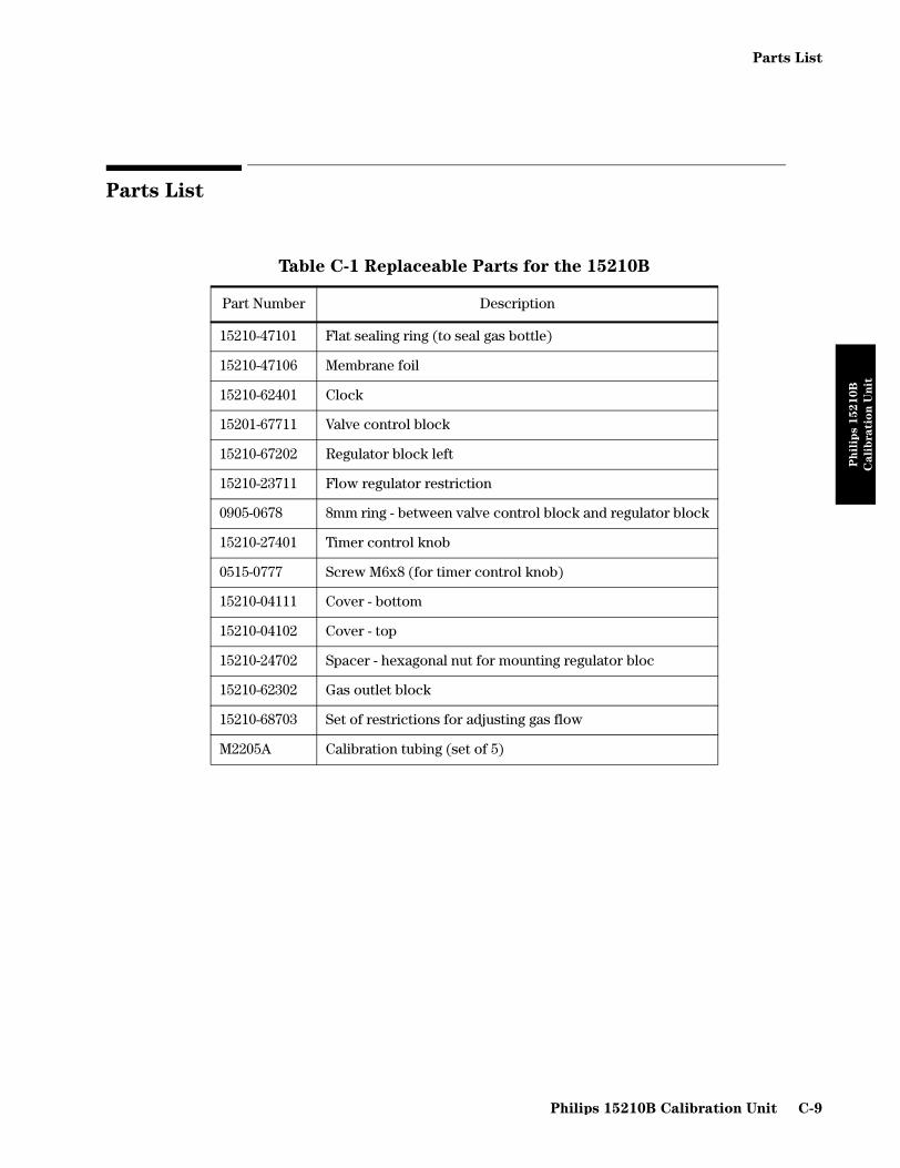
Parts List
Ph
ilip
s 1
52
10
B
Cali
bratio
nU
nit
Parts List
Table C-1 Replaceable Parts for the 15210B
Part Number Description
15210-47101 Flat sealing ring (to seal gas bottle)
15210-47106 Membrane foil
15210-62401 Clock
15201-67711 Valve control block
15210-67202 Regulator block left
15210-23711 Flow regulator restriction
0905-0678 8mm ring - between valve control block and regulator block
15210-27401 Timer control knob
0515-0777 Screw M6x8 (for timer control knob)
15210-04111 Cover - bottom
15210-04102 Cover - top
15210-24702 Spacer - hexagonal nut for mounting regulator bloc
15210-62302 Gas outlet block
15210-68703 Set of restrictions for adjusting gas flow
M2205A Calibration tubing (set of 5)
Philips 15210B Calibration Unit C-9
Parts List
Ph
ilip
s 1
52
10
B
Cali
bratio
nU
nit
C-10 Philips 15210B Calibration Unit

Appendix D CPC Programming Tool Manual
CP
C P
ro
gram
min
g T
oo
l
Man
ual
Introducing the CPC Programming Tool
The CPC Programming Tool provides a means of servicing and upgrading Philips products which utilize Flash memory technology. The tool interfaces to devices that have a human interface via a service port connector, and in the future will use an RS232 connector for devices without a human interface. The service port cable which is provided is a 20-wire ribbon cable and is 18 inches long.
This manual provides the functional description and troubleshooting procedures of the Philips CPC Programming Tool. Programming procedures are found in the installation note for the specific product being programmed.
Figure D-1 Philips CPC Programming Tool connected to a Service Port.
Parts Checklist
The Philips CPC Programming Tool Kit (M2300-67100) contains the following parts:
• Philips CPC Programming Tool (ET-36733)
• Service Port Ribbon Cable (M2300-67200)
• Ground Cable (M2300-67210)
CPC Programming Tool Manual D-1

Introducing the CPC Programming Tool
CP
C P
ro
gram
min
g T
oo
l
Man
ual
Power Requirements
The CPC Programming Tool draws +5 Vdc from the host product to arm the internal Vpp converter and power the internal circuitry.
Host Product Compatibility
The following products can use the CPC Programming Tool:
• CMS Patient Monitoring System (all models)
• Anesthesia CMS Patient Monitoring System (all models)
• Component Central Monitor (all models)
• Component Transport System
Accessories
To use the tool, you will also need a product-specific Programming Card, which is ordered separately from the Philips Support Materials Organization (SMO) or Philips Parts Center Europe (PCE).
There are two types of Programming Cards for most products; one is intended for the customer and the other for Philips internal personnel performing warranty functions. For example, the Philips CMS Patient Monitoring System has the CPC Programming Card and the CPC Programming Card – Philips Internal Only. Both cards are programmed for the same basic functions but the Philips Internal Only card can perform warranty-specific functions and is available only to Philips personnel.
D-2 CPC Programming Tool Manual

CPC Programming Tool Functional Description
CP
C P
ro
gram
min
g T
oo
l
Man
ual
CPC Programming Tool Functional Description
The Philips CPC Programming Tool consists of a protective case housing a single printed circuit board (PCB) and the Programming Card slot. The host product specific Programming Card is inserted into the programming tool by sliding the card into the tool until it snaps into place. The card can be removed by pressing the card eject button.
All of the functional circuits of the programming tool are contained on the PCB. The PCB can be broken down into the following functional areas:
• Programming Card Interface
• Internal tool EEPROM
• VPP converter
• DIP switches
• Service Port connector
• RS-232 connector
• LED indicators
Programming Card Interface
The main component of the programming tool is the Programming Card interface. The Programming Card is specific for each host product. The Programming Card contains the current or new version of the host product software and boot program to provide the programming functionality. The speed of the data transfer from the Programming Card to the host product is dictated by the speed at which the host product updates its internal ROM. This varies from product to product. Upgrade data is downloaded to the host product at boot up when the dip switches on the programming tool are configured properly and the Programming Card is inserted properly. This inserts a boot signal on the host product, causing the host product to change its address map and boot from the Programming Card. The host product then copies appropriate routines to its RAM and executes the routines from there, with additional accessing of the Programming Card for byte reads of the upgrade code.
Internal EEPROM
The programming tool contains two separate 32K x 8 EEPROM.
CPC Programming Tool Manual D-3

CPC Programming Tool Functional Description
CP
C P
ro
gram
min
g T
oo
l
Man
ual
VPP Converter
The VPP converter is a 5VDC to 12VDC converter that supplies power to program four Flash chips at 12VDC at 120 mA. If the host product supplies 12VDC, the VPP converter is turned off by the tool's internal software.
DIP Switches
The programming tool contains eight DIP switches that are read during programming tool operation. The switches are set specifically to interface with the software running in the host product.
Service Port Interface
The service port interface is a 32 Kbyte address space extension allowing the host product read/write access to the programming tool. A signal from the tool indicates to the host product hardware to remap the service port. When this is active, the host product maps the programming tool's 32 K address space. The CPC vectors and boot routine are now accessed from the Programming Card through the service port. Because the service port address space is limited, the addressing of the Programming Card is done through bank switching. A bank is defined as continuous blocks of 8 Kbytes. The service port is set up as four banks.
Data
Transfer
Byte wide bus transfers are completed between the tool and the host product. The data transfer can be in either direction.
Boot Up The boot routine is inserted by the programming tool upon the host product power up if DIP switches are set properly and a Programming Card is properly inserted into the tool. The boot routine causes the host product to boot from the Programming Card instead of the host product boot code.
RS232
Interface
The RS-232 interface is not yet supported, but in the future it will provide several functions for the tool. For a host product without a human interface, a PC will be connected to the product through the tool. In this setup, the host product will be upgraded by moving data directly from a floppy to the Flash ROM of the product.
LED
Indicators
Three LED indicators (one red, two green) provide visual indications of the status of the programming tool and the status of the function being performed.
These LEDs are labeled on the programming tool as follows:
• STATUS (green)
• PASS (green)
• FAIL (red)
D-4 CPC Programming Tool Manual

Before Using the CPC Programming Tool
CP
C P
ro
gram
min
g T
oo
l
Man
ual
Before Using the CPC Programming Tool
To prevent damage, do not handle the Philips CPC Programming Tool until the following conditions are met:
• An anti-static mat must be used.
• In addition to the table mat, the person performing the upgrade operation should either:
• Wear a conductive wrist strap attached to the host product chassis by the wire included with the strap, or
• Stand on a floor mat with leather-soled shoes. The floor mat also has an isolation resistor in series with its ground lead for personnel protection.
• When transporting PCBs, carry them in their shipping containers.
• To protect CMOS integrated circuits (ICs), never transport them loose since it may result in damaging them by a static discharge or in damaging or misaligning their pins.
• When transporting PCB’s, carry them in their shipping containers.
• To protect CMOS integrated circuits (ICs), never transport them loose since it may result in damaging them by a static discharge or in damaging or misaligning their pins
• Before handling any PCBs, firmly touch the exposed metal on the case of the tool to equalize the ground potentials. This prevents static discharge and protects CMOS logic components.
• Handle PCBs by the edges only. Avoid touching PCB surfaces unless replacing components. Contaminants such as skin-oil cause dust to accumulate which can retain moisture and damage the circuits.
NOTE Before using the CPC Programming Tool on any Philips product, make a list of the user configuration settings that will be set to default values when performing a standard upgrade.
CAUTION
CPC Programming Tool Manual D-5

Using the CPC Programming Tool
CP
C P
ro
gram
min
g T
oo
l
Man
ual
Using the CPC Programming Tool
The following procedures describe the general uses of the CPC Programming Tool.
NOTE Before using the Philips CPC Programming Tool on any monitor make a list of the user configuration settings that will be set to default values when performing a standard upgrade.
Before connecting the CPC Programming Tool the monitor must be turned off. Failure to do this could cause the CPC Programming Card in the tool to be corrupted.
The monitor must always be connected to AC power during the upgrade operations. Connecting the unit to AC power insures the unit is connected to earth ground, decreasing the likelihood of damage to the unit due to ESD.
Connect the Tool
To connect the CPC programming tool to a monitor, perform the following procedure:
Step 1 Turn the monitor OFF.
Step 2 Expose the Flash Upgrade service port on the monitor. The location of the port is monitor dependent.
Step 3 Attach the ground wire to the CMS.
Step 4 Attach either end of the ribbon cable to the tool, then plug the other end of the cable into the Flash Upgrade service port.
Step 5 Insert the appropriate CPC Programming Card into the tool.
Step 6 Check the switch settings on the CPC Programming Tool.
Step 7 Turn the monitor ON. The screen displays the status message Config Mode Active - NO MONITORING! accompanied by text which identifies the version of the programming tool being used.
If the system does not respond as expected, see the Troubleshooting section at the end of this note.
CMS All switches down
ACMS Switch 2 is up, all other switches down
CTS All switches down
CCM Switch 1 is up, all other switches down
D-6 CPC Programming Tool Manual

Using the CPC Programming Tool
CP
C P
ro
gram
min
g T
oo
l
Man
ual
Step 8 Press or to display the Instrument Configu-ration or setup screen. The screen displays the softkeys that are specific to the monitor’s software. To provide security against unauthorized use, some of the softkeys are disabled (darkened) until the password is entered.
Enter the Password
To enter the password, select the softkey followed by the password. The default password is 1175.
NOTE Make sure to keep the password in a secure place, or remember it. The password should not be given out to people who are not authorized to perform upgrades.
The password is stored in memory in the tool and does not reside in the CPC Programming Card.
For more information on using the tool to perform an upgrade, see the Installation Note for the specific release of your monitor.
Create or Change the Password for the Tool
Once the password is changed, it cannot be changed back to the default password.
Step 1 Select the softkey followed by the default password (1175) or the current password if the password has already been set. Read the security message and press or .
Step 2 Select the softkey again and enter the desired password. A password can be between five and nine digits.
Step 3 Re-enter the password to confirm it and then press or to leave the password task window.
Edit the Monitor Serial Number (Philips Internal Only)
The softkey is available if a new (empty) EEPROM has been added on that board. Unauthorized changes to the serial number could affect the product warranty.
Step 1 Select the softkey, if available, to display he Edit Serial Number screen. Read the security message and press or
.
Step 2 Use the keyboard to type in the correct serial number.
Step 3 Press . The screen displays the message Please check again to make sure serial number is correct.
Instrument Config Monitor Setup
Password Entry
Password Entry
Instrument Config Monitor Setup
Password Entry
Instrument Config
Monitor Setup
Edit Serial No
Edit Serial NoInstrument Config
Monitor Setup
Confirm
CPC Programming Tool Manual D-7

Using the CPC Programming Tool
CP
C P
ro
gram
min
g T
oo
l
Man
ual
Step 4 Verify that the serial number has been entered correctly and press . The screen displays the message New serial number stored in EEPROM.
Step 5 Press or to return to the monitor setup task window.
Clone User Settings with the Tool
The CPC Programming Tool can be used to clone user settings onto new monitors of the same model and configuration (same EEPROM number). For example, if a customer has a 6-wave monitor, you can use the CPC Programming Tool to clone the user settings of that monitor onto another 6-wave monitor of the same model. To perform this procedure, you need a CPC Programming card that contains the EEPROM number of both monitors.
Step 1 Press to display the EEPROM cloning window.
Step 2 Press followed by to store the monitor's user set-tings on the CPC Programming Tool.
Step 3 The message...Reading EEPROM is displayed, followed by the mes-sage...Settings stored in local memory when the read process is complete.
Step 4 Go to the receiving monitor and attach the tool to the appropriate Flash port.
Step 5 Press to display the EEPROM cloning window.
Step 6 Press followed by to program the monitor with the configuration settings you stored on the CPC Programming Tool.
Step 7 The message...EEPROM programming in progress is displayed, followed by the message... Programming done when the cloning process is com-plete.
Step 8 Press or to return to setup screen.
Perform Upgrades with the Tool
The CPC Programming Tool is also used to perform monitor upgrades.There are two different types of procedure that need to be performed to complete a successful upgrade: a Software Upgrade and an EEPROM Upgrade. (The Central Station has an additional upgrade called the Arrthymia upgrade.) The installation note included with the CPC Programming card will give detailed information on how to perform these procedures. The monitor will also prompt you with text messages as you perform the upgrade. In general you perform the Software upgrade and then the EEPROM upgrade. CCM finishes with the Arrthymia upgrade.
Confirm
Instrument Config Monitor Setup
EEPROM Cloning
Read Settings Confirm
EEPROM Cloning
Program Settings Confirm
Instrument Config Monitor Setup
The settings are
stored in the tool
and not in the
programming card.
D-8 CPC Programming Tool Manual

Troubleshooting the Tool through Tool LED Patterns
CP
C P
ro
gram
min
g T
oo
l
Man
ual
Troubleshooting the Tool through Tool LED Patterns
Troubleshooting the Tool through Monitor Error Messages
STATUS PASS Fail Condition/Corrective Action
ON OFF OFF Initial condition of product
ON Blinking OFF Flash upgrade in progress
ON ON OFF Flash upgrade completed
ON ON ON Interconnection failure: no communication between CPC and host;1. Check connection of programming tool to host product 2. Check that Programming Card is properly inserted in programming Tool3. Suspect bad programming tool or cable4. Suspect bad CPC Card
OFF OFF ON Checksum Error: process has been interrupted during programming; Repeat upgrade procedure; if same error occurs:1. Suspect CPC Card2. Suspect Programming Card
ON OFF ON Programming Error: hardware configuration is incorrect for the software you are programming;1. Check Programming Card part number2. Check that you are using the correct CPC port
Error Message Displayed Possible Cause/Corrective Action
SOFTWARE INCOMPLETE This message may be displayed in the alarm field at the top right of your screen after booting up. Possible causes include:
• Interrupted Flash ROM programming• Corrupt data in the Flash ROM• Blank Flash ROM• Hardware failure on CPC Card
...Memory card failure, upgrade not allowed
Check that the Programming Card being used is correct.Check that the Programming Card has not been physically damaged.
...Wrong Memory Card for this instrument
Check that the Programming Card being used is correct. Check that the CPC is in the correct slot
...Change of memory Card not allowed
This message will be displayed if the Programming Card is exchanged within the programming tool during an operation.
CPC Programming Tool Manual D-9

Troubleshooting the Tool through Monitor Error Messages
CP
C P
ro
gram
min
g T
oo
l
Man
ual
...Tool disconnected, connect and try again
Check that the tool has not disconnected from the service port during operation.Check the connections of the 20-wire ribbon cable to the tool and CPC port.Check the physical condition of the 20-wire ribbon cable. The signal continuity of the cable (Philips M2300-67210) may deteriorate with repeated use. Philips recommends that you replace this cable approximately every three months, or more frequently if the cable displays signs of deterioration.
..Memory Card ejected, insert and try again
This message will be displayed if the Programming Card is ejected from the programming tool during an operation.
...Programming failed, please retry
Retry the operation; if this condition is not corrected upon retrying 5 times, the message...Software upgrade failed, upgrade not possible will be displayed (see below).
...Software upgrade failed, upgrade not possible
Possible defective Flash ROM or CPC; CPC must be replaced.
...Software incomplete, upgrade software first
This message will be displayed during an EEPROM Upgrade operation if the Flash ROM software of the current CPC is incomplete. You must perform a Software Upgrade before the EEPROM Upgrade can be performed.
...Software not upgraded, upgrade software first
This message will be displayed during an EEPROM Upgrade operation if the current software release and the selected EEPROM part number do not match. You must perform a Software Upgrade before the EEPROM Upgrade can be performed.
Error Message Displayed Possible Cause/Corrective Action
D-10 CPC Programming Tool Manual

Glossary
A
Alphanumeric Keys - These are single press keys used to input patient information and drug calculations into the monitor.
B
Backplane - The backplane of the Computer Module contains the connections for the front and rear function cards.
Blank Rack - The blank rack is used to cover the front of the Computer Module when a Satellite Rack is being used. It is the interface for Satellite Racks to the system and contains a rear connector that outputs information from the rack to the Computer Module.
C
Classic Control Panel - The hardkeys, softkeys and alarm indicators of the Classic human interface (Release D or earlier). Available with and without the SUSPEND key (See Chapter 6 “Parts List for CMS”).
Cold Start - During a cold start the CPU Cards run a detailed test of memory which erases the system database for patient data management. All active settings and patient data is lost.
Computer Module - The Computer Module contains the hardware and software for the processing functions of the monitor. Most of the external connections of the monitor are in the rear of the Computer Module.
CPC Flash Port - This port is located on the Configurable Processor Card (CPC) in slot 12 and is the connector for the CPC Programming Tool.
D
Double-width Module - The term double-width is used to designate that the module occupies two slots in the module rack.
E
Error Codes - Whenever one of the function cards is unable to perform an operation, an error code is generated. Error codes can be for fatal and non-fatal errors.
Extended Test - During the extended self-test the CPU Cards run a detailed memory test erases the system database for patient data management. All patient data is lost as the memory test is equivalent to a cold start.
F
Fatal Errors - Fatal errors are errors which cause the CMS to re-start.
Front Panel -The plastic bezel on the front of the monitor that contains controls and connectors, including the control panel and CRT adjustments.
G
Grounding Terminal - The Computer Module and Display Module of the CMS each have a ground terminal stud which allows connection to an equipotential grounding system.
H
Handheld Keypad - The Handheld Keypad is an input device used on the Main Display to interact with patient data management and drug calculator software.
Hardkeys - These are single press keys with labels used as selection controls. Typically, hardkeys access the Selection Window of its label.
HIF Connector - The Human Interface Connector is a Human Interface Link (HIL) connector used on a main display to attach the Handheld Keypad.
Hot Start - The Monitor makes a hot start when it has been powered down for a period less than one minute. The active user default values, including parameter
Glossary-1

module settings are recovered and retained on restart.
Philips Network - The Serial Distribution Network of the CMS (also known as CareNet or SDN).
I
INOP - Inops are messages displayed on the screen when the CMS cannot measure or process signals properly. This could be due to patient-related or equipment-related problems.
Instrument Grounding - The detachable three-wire power cable grounds the instrument to the power line ground when plugged into an appropriate three-wire receptacle. This cable protects both the patient and the hospital staff.
Integral Plug-in Module Rack - The integral plug-in module rack fits in the front of the Computer Module and hold plug-in modules. It contains a rear connector that is used to output information from the rack to the Computer Module.
L
Line Voltage Selection - Switch-mode power supply automatically selects the necessary line voltage for the system. The fuse values corresponding to the switch-mode power supply are listed in Chapter 5 “Repairing the CMS”.
Local Bus - This is the local communication system. It is a buffered processor bus that allows access to local memory cards, SRAM and EPROM that contain software for the exclusive use of the master processor.
Local Clusters - The local bus is connected to all the connectors in the backplane but it is interrupted to form clusters that share a connection to the same local bus. There are 10 local clusters in the backplane with varying numbers of connectors.
Locking Cam - A Locking Cam is a plastic latch used to lock the Display Module or Computer Module into place.
M
Main Display Module - Main Displays are 14" CRT (Mono or Color) or 10.4" Flatscreen with integrated Control Panel for the human interface, or XGA display.
Main Screen - This screen shows the waveforms and numerical readouts of the parameters you have chosen to monitor, alarms, INOP messages, bed label, date and time, and arrhythmia messages (when assigned).
Membrane Keypad - The plastic bezel on the front of the Handheld Keypad that contains the controls and connectors, including the control panel and alphanumeric keypad.
Message Passing Bus - This is the global communication bus for the system, and is used for communications between CPU cards as well as to intelligent interface cards. This bus appears on all the connectors.
Mounting Plate - The Mounting Plate is a metal plate with slots used to attach a Display Module or Computer Module with feet to a flat surface.
N
Non-fatal Errors - Non-fatal errors are general errors that are not significant enough to affect normal CMS operation.
P
Parameter - The parameter of the plug-in module is the specific clinical measurement performed by the module. Some modules, like the ECG/Resp module, are capable of monitoring more that one parameter.
Plug-in Module Rack (Integral or Satellite) - The Plug-in Module Rack is the interface between the plug-in modules and the Computer Module. Module racks can be integrated in the Computer Module or remotely located in the patient vicinity.
Glossary-2

Plug-in Modules - The plug-in modules are the interface between the patient cables and the Plug-in Module Rack. Each module is responsible for specific measurements. The number and type of modules used will depend on the monitoring situation.
R
Rear Panel - The panel on the rear of the display that contains the CRT controls and power, HIL and video connectors.
Remote Display Module - Remote displays are 14" Mono, 14" Color or 21" Color without Control Panels.
Remote Power Supply - The Remote Power Supply provides the power for the Flatscreen Display, Function Box and Frontend Modules.
S
Satellite Rack - An external rack, which is mounted separately from the CMS. It is used to provide expanded space for your plug-in modules.
Selection Window - The Selection Window is the first operating level where you can choose a specific activity or function. It is entered through a hardkey on the control panel or the remote keypad.
Self-Test - This Philips monitor has a module self-test which generates and displays test waveforms and corresponding numerics for all the modules that are connected through a rack and turned on.
Single-width Module - The term single-width module is used to designate that the module occupies only one slot in the module rack.
Softkeys - These are single-press keys used as selection controls to enter Task Windows and they correspond to the softkey labels displayed above them on the screen.
Spanning Rails - The spanning rails are metal rails that can be attached to the bottom of a Display Module or Computer Module to provide a mounting surface for an adapter plate. The spanning rails are attached to the module using the mounting feet holes.
Specification Tests - Specification tests are test which a hospital biomedical engineer can use to check the performance of parameter modules with general, special and manufactured test equipment.
Standard Control Panel - The hardkeys, softkeys and alarm indicators of the Standard human interface (Release E or later).
Start-Up Error Codes - Start-up error codes give similar information to the Status Log entries, except the codes are given are in hexadecimal notation.
Status Message - The status message is a string of text displayed in the top center of the screen below the date and time. A message is displayed in status line to indicate the current operating mode if not Monitoring.
T
Task Window - The task window is the second operating level which allows you to make changes or adjustments to the parameters and screen displays, or to perform procedures.
U
Utility Bus - This includes functions required by the whole system, for example, power and clock signal distribution. This bus appears on all the connectors.
V
Video Termination - The video termination switch on the Display Module is switched ON if only one display is used. If slave displays are used, the switch is turned OFF on all displays except the last display in the chain.
W
Wall Channel - The wall channel is a metal channel that attaches to a wall and allows mounting options to be adjusted vertically to the desired height.
Glossary-3

Wall Hanger - The Wall Hanger is a metal bracket that is used to hang the Computer Module below a mounting arm.
Warm Start - During a warm start the System behaves as during a cold start, but an abbreviated version of the self-test is carried out. The system database for patient data management is checked and recovered. All active settings are lost.
X
X-Start - During an X-start, the system reacts as after a cold start, the only difference being that the user default settings of the Monitor are downloaded to the EEPROM of the modules. An X-start occurs after changing operating mode or configuration set
Glossary-4

INDEX
AAccessing & Leaving Service Mode, 39Accuracy and Calibration Procedures
SvO2 Optical Stability Check, 60Touch Screen, 47XGA Display, 46
BBoot Process, 48
CChanging Operation Modes, 68Classic Control Panel Controls, 10Cleaning Procedures, 23Cleaning the Blood Analysis Module, 27Computer Module, 19
Brief Functional Overview, 20Delivered Configurations, 21External Connector Pinouts, 36Function Cards, 21
DDevice ID Codes, 17
Operating System 16400 (or 4010H), 18Processor Device ID Codes, 34Software ID Codes, 33
Display Fuse Values, 54Display Module with Dimensions, 7
EEEPROM/CPU Matrix (M1059-85xxx), 28EEPROM/CPU Matrix (M1059-87xxx), 30, 32Error Code Lists for Other Device IDs, 28Error Codes
Using Start-up Error Codes, 16Using Status Log Error Codes, 16What an Error Code Tells You, 15
Exploded ViewComputer Module Exploded View, 18Display Module Exploded View M1092A/
M1094A, 9Display Module Exploded View M1094B, 8Double-width Plug-in Module Exploded View, 29Single-width Plug-in Module Exploded View, 28
FFront Panel Controls and Connectors, 7, 8Function Cards of the Computer Module, 21
GGeneral Inspections of the System, 19
HHardware Configuration Problems, 23Hardware/Software Problems, 27
IIntegral Rack, 55
LLoudspeaker Test, 27
MMain Display Module, 4Maintaining CMS, 1Maintenance Procedure Overview, 2Mouse
Adjusting Pointer Speed, 50Configuration, 49
OOperating Mode
Configuration Mode, 67Demo Mode, 66Monitoring Mode, 66Service Mode, 67
Operating Rules to Remember, 66
PPlug-in Module Accessories
Cardiac Output Module, 40CO2 Module, 41ECG & ECG/Respiration Module, 34FIO2 Module, 43Non-Invasive Pressure Module, 38Pressure Module, 37Sidestream CO2 Module, 42SpO2 Module, 44SvO2 Module, 42tcpO2/tcpCO2 Module, 45Temperature Module, 44Thermal Array Recorder Module, 45
Plug-In Module Control Panel Keys and Indicators, 59Plug-in Module Pin-outs, 63Plug-In Module Self-Tests, 54Printers
Local Jet Printer Configurations, 37
RRAM Problems, 27Remote Display Front Panel Controls, 14Remote Display Module, 13Remote Display Rear Panel Controls and Connectors, 14Remote Keypad, 16Remove/Replace
Computer ModuleCentre Plane Board Assy, 58DC/DC Converter, 46Front Function Card, 51Integral Rack, 47Locking CAM, 60Plastic Feet, 59Rear Cover, 45
Index-1

Rear Function Cards, 54Side Cover, 56Top Cover, 57
M1092A and M1094AFront Assembly, 11Fuse Assembly, 16Human Interface Board, 12Line Power Filter (M1094A Display), 8Locking Cam, 10Membrane Switch, 13Metal Cover, 14Power Fail Relay (French ICU Option), 5Power Fuses, 6, 48Rear Cover, 4Rear Enclosure, 9Switch-Mode Power Supply (M1092A), 18Switch-Mode Power Supply (M1094A), 20Video/Philips-HIL Connector PCA, 22
M1094BFront Assembly, 28Human Interface Board, 29Locking Cam, 27Membrane Switch, 30Power Fuses, 24Rear Enclosure, 26Switch-Mode Power Supply, 33Top Metal Cover and SMPS Cover, 32
Plug-in ModuleFIO2 Battery, 70NBP Inlet Connector Insert, 67NBP Pump, 68Plug-In Module Disassembly, 65Recorder Module Paper, 71Snap Lock, 64tcpO2/tcpCO2 Calibration Chamber, 69
Plug-in Module RackMounting Clamp, 62Plug-In Module, 61
Remote KeypadHousing Assembly, 41
Replacable Parts - Display Module, 3, 7Replaceable Parts - Computer Module, 11, 13, 15, 19Replaceable Parts - External Alarm Device, 14Replaceable Parts - Handheld Keypad, 32, 33Replaceable Parts - Module Racks, 32Replaceable Parts - Plug-In Modules, 25, 26Replaceable Parts for the Display Module, 3RS-232 Port Configuration, 45Rules for Card Placement, 24
SSafety Test Diagrams, 12Safety Tests, 11Satellite Rack, 55Service Mode
Changing the Global Switches, 40Checking the Hardware and Software Revisions, 43Displaying the Status Log, 42French Homologation, 42Line Frequency, 40Network Test, 45Power On Modes, 44RS232 Interface, 42Setting the Altitude, 42Setting the Date and Time, 42Settings Transfer, 41
Standard Control Panel, 5Standard Control Panel Controls, 9
TTest and Inspection Matrix, 5Test and Inspection Matrix - Safety, 11Test and Inspection Requirements, 3Testing the CMS, 1Touch Screen
Calibration, 47Trackball
Adjusting Pointer Speed, 50Configuration, 49
TroubleshootingGeneral System Troubleshooting, 3Procedure Overview, 2Troubleshooting Module 1 - Fixing Display
Problems, 7Troubleshooting Module 2 - Computer Module
Faults, 14Troubleshooting Module 3 - Fixing Recorder
Problems, 35Troubleshooting Module 4 - Fixing Remote Keypad
Problems, 36Troubleshooting Module 5 - Fixing Printing
Problems, 37Troubleshooting Module 6 - Using the Service
Mode, 39Troubleshooting Plug-in Modules
Blood Analysis Module Problems, 35, 52Cardiac Output Problems, 17CO2 Module Problems, 32ECG and ECGRESP Problems, 9EEG Module Problems, 40NBP Problems, 13Pressure Problems, 11SpO2/Pleth Problems, 22Sv02 Problems, 24tcpO2/tcpCO2 Problems, 3Temperature Module Problems, 28
UUpgrade Tools & Miscellaneous Parts, 22, 24
Index-2

VVideo / Power Connector, 37
XXGA Display
Adjustments, 46
Index-3

Index-4