Embed Size (px)
Citation preview
Canada25 Interchange WayVaughan, ON L4K 5W3Tel: 905-660-4655 Fax: 905-660-4113
Mircom 2004Printed in CanadaSubject to change without prior notice
U.S.A.4220 Steve Reynolds Blvd, Unit 17Norcross (Atlanta), GA 30093Tel: 1-888-660-4655 Fax: 1-888-660-4113 www.mircom.com
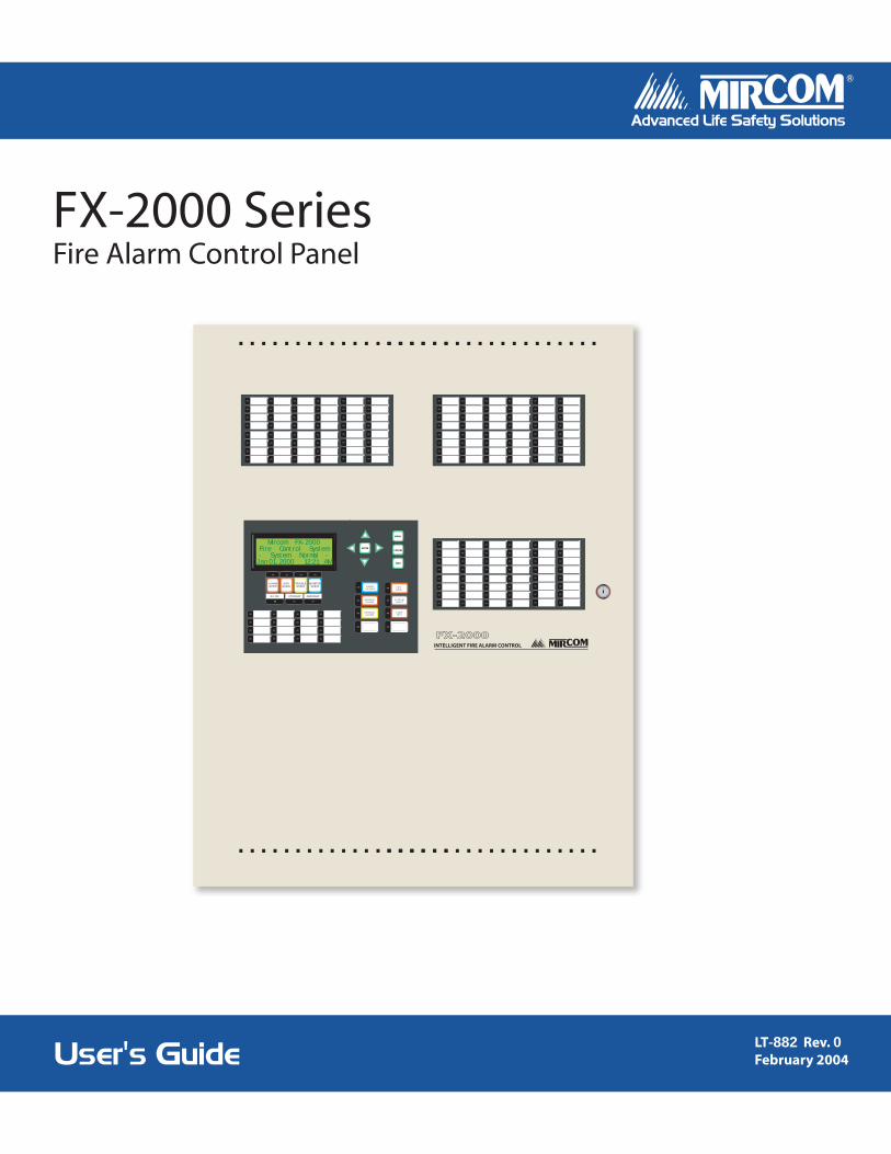
FX-2000 SeriesFire Alarm Control Panel
LT-882 Rev. 0February 2004User's Guide
Advanced Life Safety Solutions Advanced Life Safety Solutions
FX-2000INTELLIGENT FIRE ALARM CONTROL
S UP V .QUE UE
P R E -ALAR M
Mircom FX-2000Fire Control System- System Normal -
Jan 01, 2000 12:21 AM
A.C. ON CPU FAULT GND FAULT
S IG NA LS IL E NC E
F IR EDR IL L
S Y S T E MR E S E T
G E NE R A LA L A R M
G E NE R A LA L A R M
L A MPT E S T
ENTER
ALARMQUEUE
SUPV.QUEUE
TROUBLEQUEUE
MONITORQUEUE
MENU
CANCEL
INFO

Phase 2 FX-2000 User’s Guide
i
Contents
Introduction ............................................................................................................................. 1About this Manual ................................................................................................................ 1Technical Support ................................................................................................................ 1
Front Panel Indicators, Controls, and Operation ................................................................. 2Front Panel Indicators and Control Locations ...................................................................... 2Common Indicators .............................................................................................................. 3Common Controls ................................................................................................................ 4
Troubleshooting ...................................................................................................................... 7Start Up .................................................................................................................................... 8
Menu Mode .......................................................................................................................... 9Passcodes............................................................................................................................ 10
Front Panel Menu Operation .................................................................................................. 111. Reports Menu................................................................................................................... 112. Bypass Menu ................................................................................................................... 173. Walk Test Menu ............................................................................................................... 22Alternate Menu Option #3: Manual Control Enable.............................................................. 254. Change Passcode............................................................................................................ 265. Day/Night Mode ............................................................................................................... 276. Set Time/Date .................................................................................................................. 287. Clear Event Log ............................................................................................................... 298. Clear Verification Counter ................................................................................................ 309. Auto Program................................................................................................................... 31

ii
Phase 2 FX-2000 User’s Guide
1
Introduction
About this ManualThis user’s guide provides information on using the FX-2000 Fire Alarm Control Panel Command Menu features. Using the instructions provided in this manual, you will be able to
• Print reports• Bypass devices, circuits, loops, and disconnect relays• Perform a walk test• Change your passcode
• Clear logs and counters
• Set Day/Night mode and Time
• Auto program the system
Technical SupportFor all technical support inquiries, please contact Mircom’s Technical Support Department between 8 A.M. and 5 P.M. (EDT) Monday through Friday, excluding holidays.
Email: [email protected]
Local Phone: 905-695-3535 Toll-Free Phone: 1-888-449-3535
Local Fax: 905-660-4113 Toll-Free Fax: 1-888-660-4113
Front Panel Indicators, Controls, and Operation
2
Front Panel Indicators, Controls, and Operation
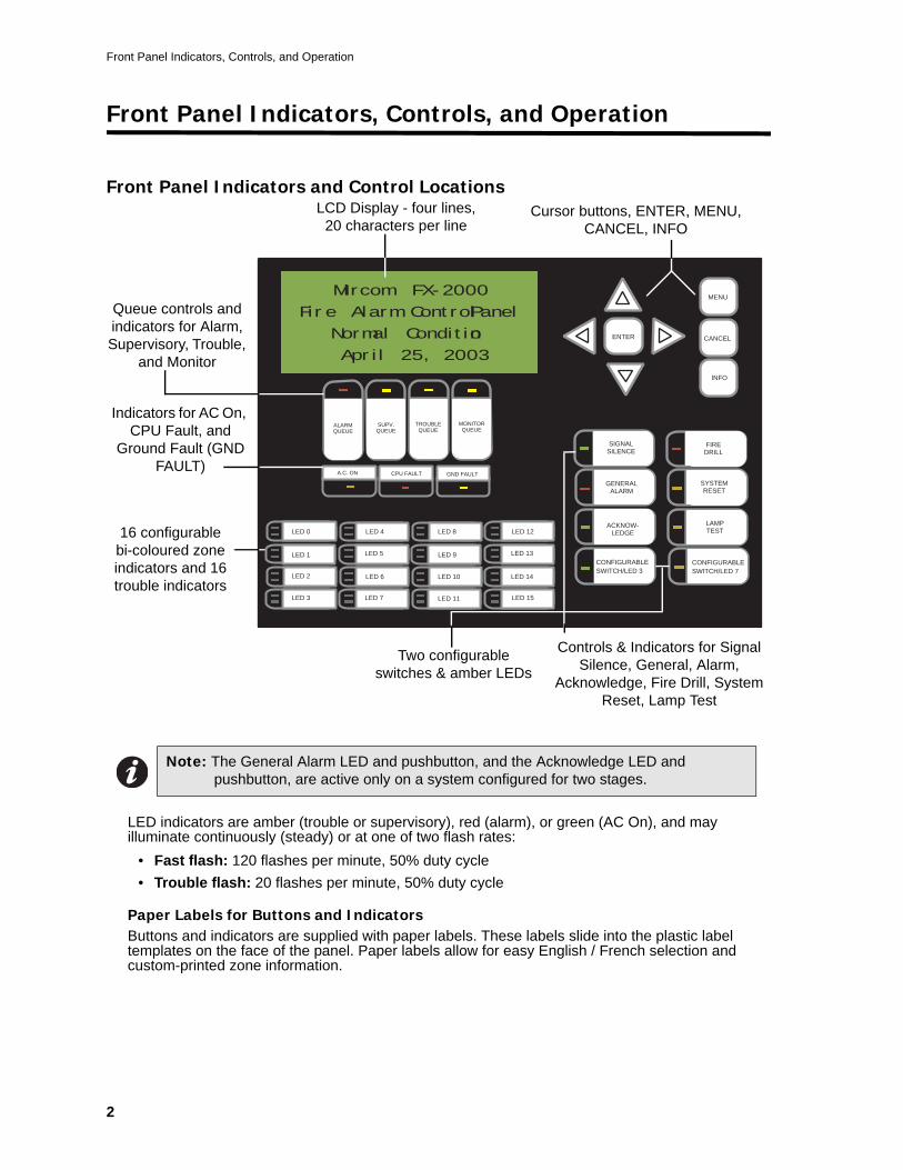
Front Panel Indicators and Control Locations
LED indicators are amber (trouble or supervisory), red (alarm), or green (AC On), and may illuminate continuously (steady) or at one of two flash rates:
• Fast flash: 120 flashes per minute, 50% duty cycle• Trouble flash: 20 flashes per minute, 50% duty cycle
Paper Labels for Buttons and IndicatorsButtons and indicators are supplied with paper labels. These labels slide into the plastic label templates on the face of the panel. Paper labels allow for easy English / French selection and custom-printed zone information.
Note: The General Alarm LED and pushbutton, and the Acknowledge LED and pushbutton, are active only on a system configured for two stages.
ALARMQUEUE
SUPV.QUEUE
TROUBLEQUEUE
MONITORQUEUE
A.C. ON CPU FAULT GND FAULT
SIGNALSILENCE
GENERALALARM
ACKNOW-LEDGE
FIREDRILL
SYSTEMRESET
LAMPTEST
ENTER
MENU
CANCEL
INFO
LED 0
LED 1
LED 2
LED 3
LED 4
LED 5
LED 6
LED 7
LED 8
LED 9
LED 10
LED 11
LED 12
LED 13
LED 14
LED 15
CONFIGURABLESWITCH/LED 3
CONFIGURABLESWITCH/LED 7
Mircom FX-2000
Fire Alarm Control Panel
Normal Condition
April 25, 2003
LCD Display - four lines, 20 characters per line
Cursor buttons, ENTER, MENU, CANCEL, INFO
Queue controls and indicators for Alarm, Supervisory, Trouble,
and Monitor
Indicators for AC On, CPU Fault, and
Ground Fault (GND FAULT)
Controls & Indicators for Signal Silence, General, Alarm,
Acknowledge, Fire Drill, System Reset, Lamp Test
16 configurable bi-coloured zone indicators and 16 trouble indicators
Two configurable switches & amber LEDs
Phase 2 FX-2000 User’s Guide
3
Common Indicators
BuzzerThe buzzer is activated by any of the following:
• Fire alarm: steady • Supervisory alarm: fast flash rate• Trouble: trouble flash rate• Monitor: Configurable to sound at trouble flash rate
If the buzzer turns on in response to a non-latching trouble or supervisory, it will turn off if the condition causing it goes away and there is no other reason for it to be on.
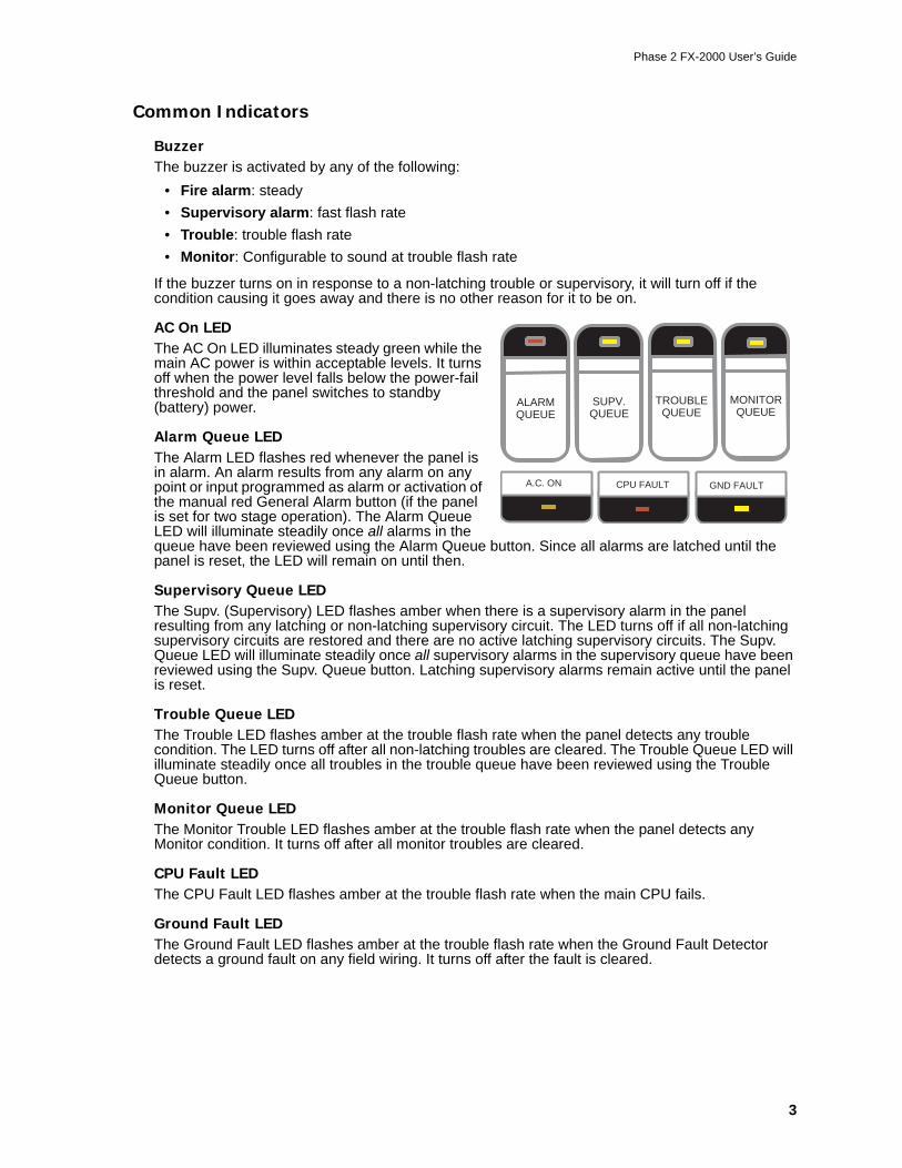
AC On LEDThe AC On LED illuminates steady green while the main AC power is within acceptable levels. It turns off when the power level falls below the power-fail threshold and the panel switches to standby (battery) power.
Alarm Queue LEDThe Alarm LED flashes red whenever the panel is in alarm. An alarm results from any alarm on any point or input programmed as alarm or activation of the manual red General Alarm button (if the panel is set for two stage operation). The Alarm Queue LED will illuminate steadily once all alarms in the queue have been reviewed using the Alarm Queue button. Since all alarms are latched until the panel is reset, the LED will remain on until then.
Supervisory Queue LEDThe Supv. (Supervisory) LED flashes amber when there is a supervisory alarm in the panel resulting from any latching or non-latching supervisory circuit. The LED turns off if all non-latching supervisory circuits are restored and there are no active latching supervisory circuits. The Supv. Queue LED will illuminate steadily once all supervisory alarms in the supervisory queue have been reviewed using the Supv. Queue button. Latching supervisory alarms remain active until the panel is reset.
Trouble Queue LEDThe Trouble LED flashes amber at the trouble flash rate when the panel detects any trouble condition. The LED turns off after all non-latching troubles are cleared. The Trouble Queue LED will illuminate steadily once all troubles in the trouble queue have been reviewed using the Trouble Queue button.
Monitor Queue LEDThe Monitor Trouble LED flashes amber at the trouble flash rate when the panel detects any Monitor condition. It turns off after all monitor troubles are cleared.
CPU Fault LEDThe CPU Fault LED flashes amber at the trouble flash rate when the main CPU fails.
Ground Fault LEDThe Ground Fault LED flashes amber at the trouble flash rate when the Ground Fault Detector detects a ground fault on any field wiring. It turns off after the fault is cleared.
ALARMQUEUE
SUPV.QUEUE
TROUBLEQUEUE
MONITORQUEUE
A.C. ON CPU FAULT GND FAULT
Front Panel Indicators, Controls, and Operation
4
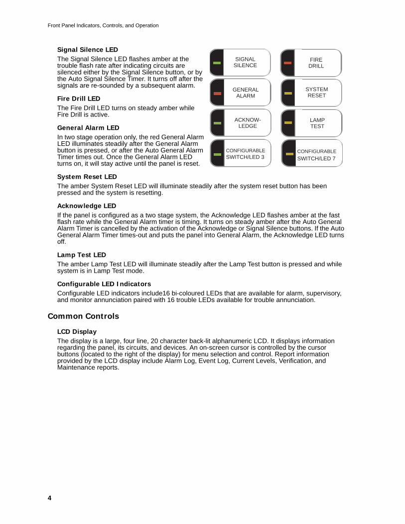
Signal Silence LEDThe Signal Silence LED flashes amber at the trouble flash rate after indicating circuits are silenced either by the Signal Silence button, or by the Auto Signal Silence Timer. It turns off after the signals are re-sounded by a subsequent alarm.
Fire Drill LEDThe Fire Drill LED turns on steady amber while Fire Drill is active.
General Alarm LEDIn two stage operation only, the red General Alarm LED illuminates steadily after the General Alarm button is pressed, or after the Auto General Alarm Timer times out. Once the General Alarm LED turns on, it will stay active until the panel is reset.
System Reset LEDThe amber System Reset LED will illuminate steadily after the system reset button has been pressed and the system is resetting.
Acknowledge LEDIf the panel is configured as a two stage system, the Acknowledge LED flashes amber at the fast flash rate while the General Alarm timer is timing. It turns on steady amber after the Auto General Alarm Timer is cancelled by the activation of the Acknowledge or Signal Silence buttons. If the Auto General Alarm Timer times-out and puts the panel into General Alarm, the Acknowledge LED turns off.
Lamp Test LEDThe amber Lamp Test LED will illuminate steadily after the Lamp Test button is pressed and while system is in Lamp Test mode.
Configurable LED IndicatorsConfigurable LED indicators include16 bi-coloured LEDs that are available for alarm, supervisory, and monitor annunciation paired with 16 trouble LEDs available for trouble annunciation.
Common Controls
LCD DisplayThe display is a large, four line, 20 character back-lit alphanumeric LCD. It displays information regarding the panel, its circuits, and devices. An on-screen cursor is controlled by the cursor buttons (located to the right of the display) for menu selection and control. Report information provided by the LCD display include Alarm Log, Event Log, Current Levels, Verification, and Maintenance reports.
SIGNALSILENCE
GENERALALARM
ACKNOW-LEDGE
FIREDRILL
SYSTEMRESET
LAMPTEST
CONFIGURABLESWITCH/LED 3
CONFIGURABLE
SWITCH/LED 7
Phase 2 FX-2000 User’s Guide
5
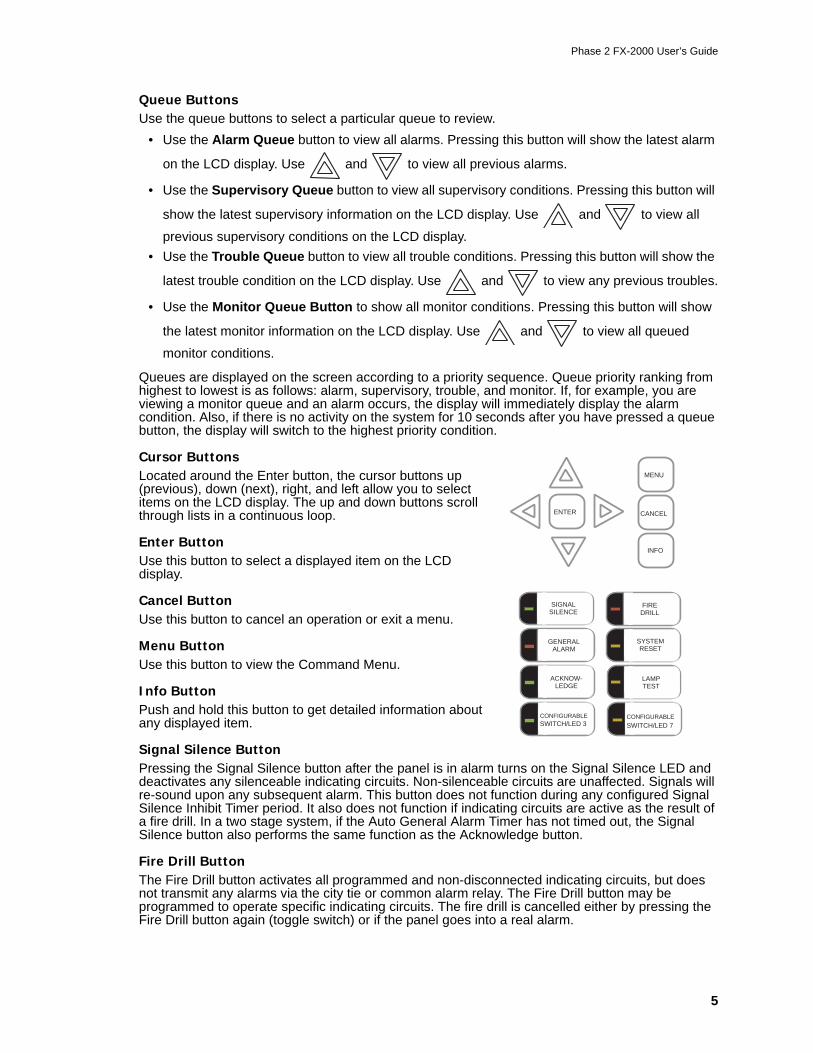
Queue ButtonsUse the queue buttons to select a particular queue to review.
• Use the Alarm Queue button to view all alarms. Pressing this button will show the latest alarm
on the LCD display. Use and to view all previous alarms.
• Use the Supervisory Queue button to view all supervisory conditions. Pressing this button will
show the latest supervisory information on the LCD display. Use and to view all
previous supervisory conditions on the LCD display. • Use the Trouble Queue button to view all trouble conditions. Pressing this button will show the
latest trouble condition on the LCD display. Use and to view any previous troubles.
• Use the Monitor Queue Button to show all monitor conditions. Pressing this button will show
the latest monitor information on the LCD display. Use and to view all queued
monitor conditions.
Queues are displayed on the screen according to a priority sequence. Queue priority ranking from highest to lowest is as follows: alarm, supervisory, trouble, and monitor. If, for example, you are viewing a monitor queue and an alarm occurs, the display will immediately display the alarm condition. Also, if there is no activity on the system for 10 seconds after you have pressed a queue button, the display will switch to the highest priority condition.
Cursor ButtonsLocated around the Enter button, the cursor buttons up (previous), down (next), right, and left allow you to select items on the LCD display. The up and down buttons scroll through lists in a continuous loop.
Enter ButtonUse this button to select a displayed item on the LCD display.
Cancel ButtonUse this button to cancel an operation or exit a menu.
Menu ButtonUse this button to view the Command Menu.
Info ButtonPush and hold this button to get detailed information about any displayed item.
Signal Silence ButtonPressing the Signal Silence button after the panel is in alarm turns on the Signal Silence LED and deactivates any silenceable indicating circuits. Non-silenceable circuits are unaffected. Signals will re-sound upon any subsequent alarm. This button does not function during any configured Signal Silence Inhibit Timer period. It also does not function if indicating circuits are active as the result of a fire drill. In a two stage system, if the Auto General Alarm Timer has not timed out, the Signal Silence button also performs the same function as the Acknowledge button.
Fire Drill ButtonThe Fire Drill button activates all programmed and non-disconnected indicating circuits, but does not transmit any alarms via the city tie or common alarm relay. The Fire Drill button may be programmed to operate specific indicating circuits. The fire drill is cancelled either by pressing the Fire Drill button again (toggle switch) or if the panel goes into a real alarm.
ENTER
MENU
CANCEL
INFO
SIGNALSILENCE
GENERALALARM
ACKNOW-LEDGE
FIREDRILL
SYSTEMRESET
LAMPTEST
CONFIGURABLESWITCH/LED 3
CONFIGURABLE
SWITCH/LED 7
Front Panel Indicators, Controls, and Operation
6
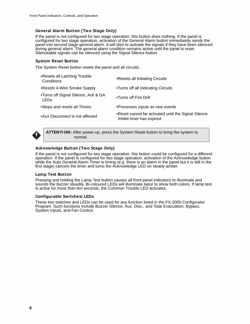
General Alarm Button (Two Stage Only)If the panel is not configured for two stage operation, this button does nothing. If the panel is configured for two stage operation, activation of the General Alarm button immediately sends the panel into second stage general alarm. It will also re-activate the signals if they have been silenced during general alarm. The general alarm condition remains active until the panel is reset. Silenceable signals can be silenced using the Signal Silence button.
System Reset ButtonThe System Reset button resets the panel and all circuits:
Acknowledge Button (Two Stage Only)If the panel is not configured for two stage operation, this button could be configured for a different operation. If the panel is configured for two stage operation, activation of the Acknowledge button while the Auto General Alarm Timer is timing (e.g. there is an alarm in the panel but it is still in the first stage) cancels the timer and turns the Acknowledge LED on steady amber.
Lamp Test ButtonPressing and holding the Lamp Test button causes all front panel indicators to illuminate and sounds the buzzer steadily. Bi-coloured LEDs will illuminate twice to show both colors. If lamp test is active for more than ten seconds, the Common Trouble LED activates.
Configurable Switches/LEDs These two switches and LEDs can be used for any function listed in the FX-2000 Configurator Program. Such functions include Buzzer Silence, Aux. Disc., and Total Evacuation, Bypass, System Inputs, and Fan Control.
•Resets all Latching Trouble Conditions •Resets all Initiating Circuits
•Resets 4-Wire Smoke Supply •Turns off all Indicating Circuits
•Turns off Signal Silence, Ack & GA LEDs •Turns off Fire Drill
•Stops and resets all Timers •Processes inputs as new events
•Aux Disconnect is not affected •Reset cannot be activated until the Signal Silence Inhibit timer has expired
ATTENTION: After power-up, press the System Reset button to bring the system to normal.
Phase 2 FX-2000 User’s Guide
7
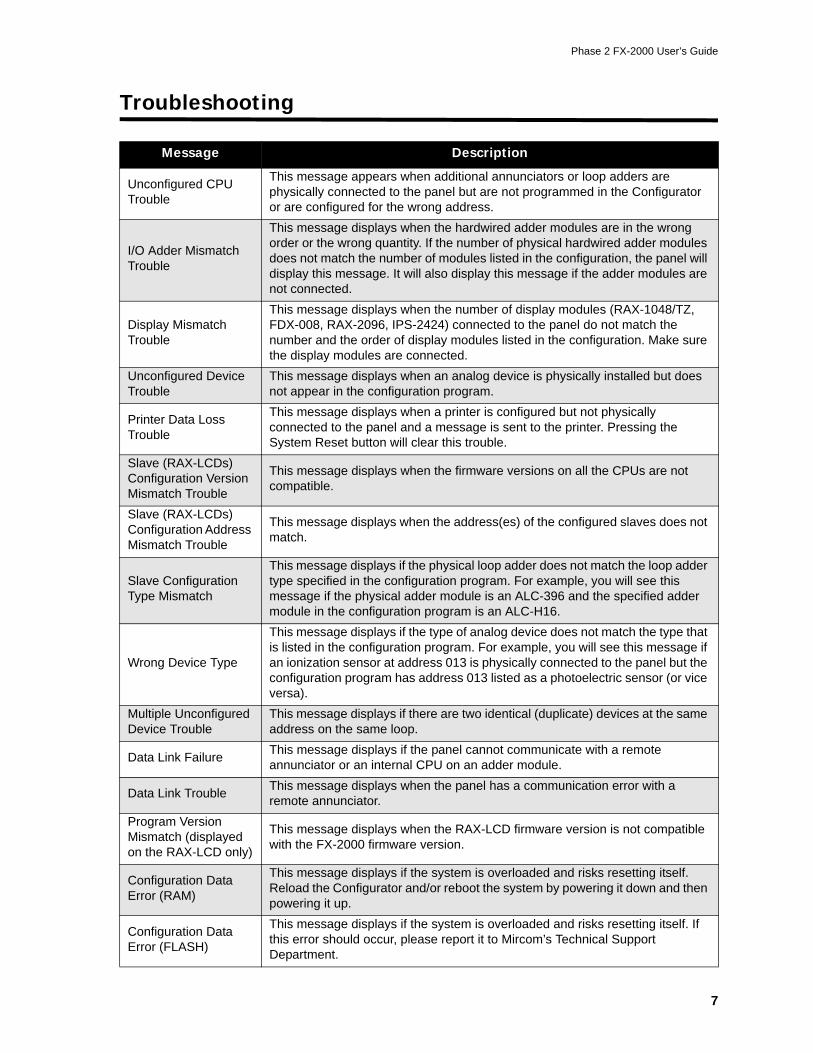
Troubleshooting
Message Description
Unconfigured CPU Trouble
This message appears when additional annunciators or loop adders are physically connected to the panel but are not programmed in the Configurator or are configured for the wrong address.
I/O Adder Mismatch Trouble
This message displays when the hardwired adder modules are in the wrong order or the wrong quantity. If the number of physical hardwired adder modules does not match the number of modules listed in the configuration, the panel will display this message. It will also display this message if the adder modules are not connected.
Display Mismatch Trouble
This message displays when the number of display modules (RAX-1048/TZ, FDX-008, RAX-2096, IPS-2424) connected to the panel do not match the number and the order of display modules listed in the configuration. Make sure the display modules are connected.
Unconfigured Device Trouble
This message displays when an analog device is physically installed but does not appear in the configuration program.
Printer Data Loss Trouble
This message displays when a printer is configured but not physically connected to the panel and a message is sent to the printer. Pressing the System Reset button will clear this trouble.
Slave (RAX-LCDs) Configuration Version Mismatch Trouble
This message displays when the firmware versions on all the CPUs are not compatible.
Slave (RAX-LCDs) Configuration Address Mismatch Trouble
This message displays when the address(es) of the configured slaves does not match.
Slave Configuration Type Mismatch
This message displays if the physical loop adder does not match the loop adder type specified in the configuration program. For example, you will see this message if the physical adder module is an ALC-396 and the specified adder module in the configuration program is an ALC-H16.
Wrong Device Type
This message displays if the type of analog device does not match the type that is listed in the configuration program. For example, you will see this message if an ionization sensor at address 013 is physically connected to the panel but the configuration program has address 013 listed as a photoelectric sensor (or vice versa).
Multiple Unconfigured Device Trouble
This message displays if there are two identical (duplicate) devices at the same address on the same loop.
Data Link Failure This message displays if the panel cannot communicate with a remote annunciator or an internal CPU on an adder module.
Data Link Trouble This message displays when the panel has a communication error with a remote annunciator.
Program Version Mismatch (displayed on the RAX-LCD only)
This message displays when the RAX-LCD firmware version is not compatible with the FX-2000 firmware version.
Configuration Data Error (RAM)
This message displays if the system is overloaded and risks resetting itself. Reload the Configurator and/or reboot the system by powering it down and then powering it up.
Configuration Data Error (FLASH)
This message displays if the system is overloaded and risks resetting itself. If this error should occur, please report it to Mircom’s Technical Support Department.
Start Up
8
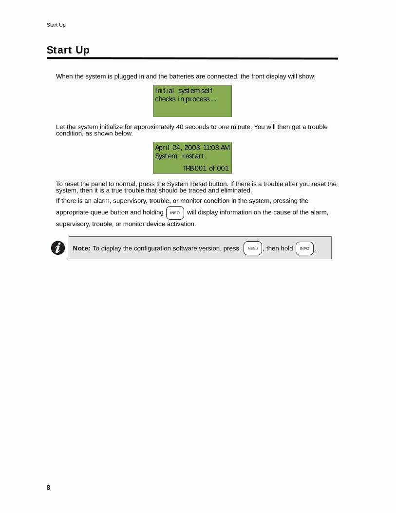
Start Up
When the system is plugged in and the batteries are connected, the front display will show:
Let the system initialize for approximately 40 seconds to one minute. You will then get a trouble condition, as shown below.
To reset the panel to normal, press the System Reset button. If there is a trouble after you reset the system, then it is a true trouble that should be traced and eliminated.If there is an alarm, supervisory, trouble, or monitor condition in the system, pressing the
appropriate queue button and holding will display information on the cause of the alarm,
supervisory, trouble, or monitor device activation.
Note: To display the configuration software version, press , then hold .
Initial system self
checks in process .. .
April 24, 2003 11:03 AM
System restart
TRB 001 of 001
INFO
MENU INFO
Phase 2 FX-2000 User’s Guide
9
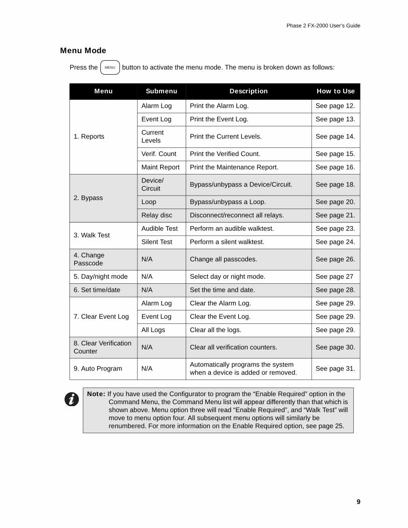
Menu Mode
Press the button to activate the menu mode. The menu is broken down as follows:
Menu Submenu Description How to Use
1. Reports
Alarm Log Print the Alarm Log. See page 12.
Event Log Print the Event Log. See page 13.
Current Levels Print the Current Levels. See page 14.
Verif. Count Print the Verified Count. See page 15.
Maint Report Print the Maintenance Report. See page 16.
2. Bypass
Device/Circuit Bypass/unbypass a Device/Circuit. See page 18.
Loop Bypass/unbypass a Loop. See page 20.
Relay disc Disconnect/reconnect all relays. See page 21.
3. Walk TestAudible Test Perform an audible walktest. See page 23.
Silent Test Perform a silent walktest. See page 24.
4. Change Passcode N/A Change all passcodes. See page 26.
5. Day/night mode N/A Select day or night mode. See page 27
6. Set time/date N/A Set the time and date. See page 28.
7. Clear Event Log
Alarm Log Clear the Alarm Log. See page 29.
Event Log Clear the Event Log. See page 29.
All Logs Clear all the logs. See page 29.
8. Clear Verification Counter N/A Clear all verification counters. See page 30.
9. Auto Program N/A Automatically programs the system when a device is added or removed. See page 31.
Note: If you have used the Configurator to program the “Enable Required” option in the Command Menu, the Command Menu list will appear differently than that which is shown above. Menu option three will read “Enable Required”, and “Walk Test” will move to menu option four. All subsequent menu options will similarly be renumbered. For more information on the Enable Required option, see page 25.
MENU
Start Up
10
Passcodes
Factory DefaultsPasscodes provide three different levels of menu access. These levels are set during configuration and are available on the following features:
• Reports• Aux. Bypass• Device Bypass• Loop Bypass• Walk Test• Change Passcode• Set After Hours• Set Time/Date• Clear Event Log• Clear Verification Count• Auto Program• Manual Enable
Changing and entering your passcodeFor instructions on how to change and enter passcodes in the system, see page 26.
Note: You can change these access levels via the Configurator.
Phase 2 FX-2000 User’s Guide
11
Front Panel Menu Operation
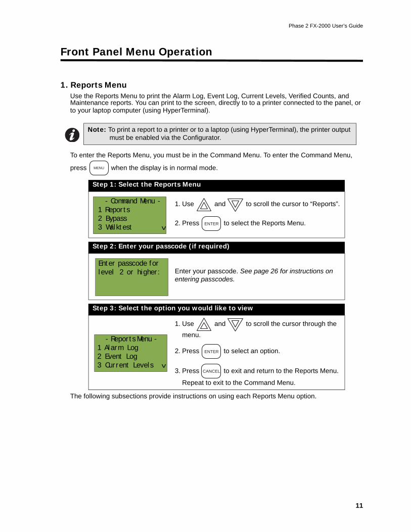
1. Reports MenuUse the Reports Menu to print the Alarm Log, Event Log, Current Levels, Verified Counts, and Maintenance reports. You can print to the screen, directly to to a printer connected to the panel, or to your laptop computer (using HyperTerminal).
To enter the Reports Menu, you must be in the Command Menu. To enter the Command Menu,
press when the display is in normal mode.
The following subsections provide instructions on using each Reports Menu option.
Note: To print a report to a printer or to a laptop (using HyperTerminal), the printer output must be enabled via the Configurator.
Step 1: Select the Reports Menu
1. Use and to scroll the cursor to “Reports”.
2. Press to select the Reports Menu.
Step 2: Enter your passcode (if required)
Enter your passcode. See page 26 for instructions on entering passcodes.
Step 3: Select the option you would like to view
1. Use and to scroll the cursor through the
menu.
2. Press to select an option.
3. Press to exit and return to the Reports Menu.
Repeat to exit to the Command Menu.
MENU
- Command Menu -
1 Reports
2 Bypass
3 Walktest
^ ENTER
Enter passcode for
level 2 or higher:
- Reports Menu -
1 Alarm Log
2 Event Log
3 Current Levels
^
ENTER
CANCEL
Front Panel Menu Operation
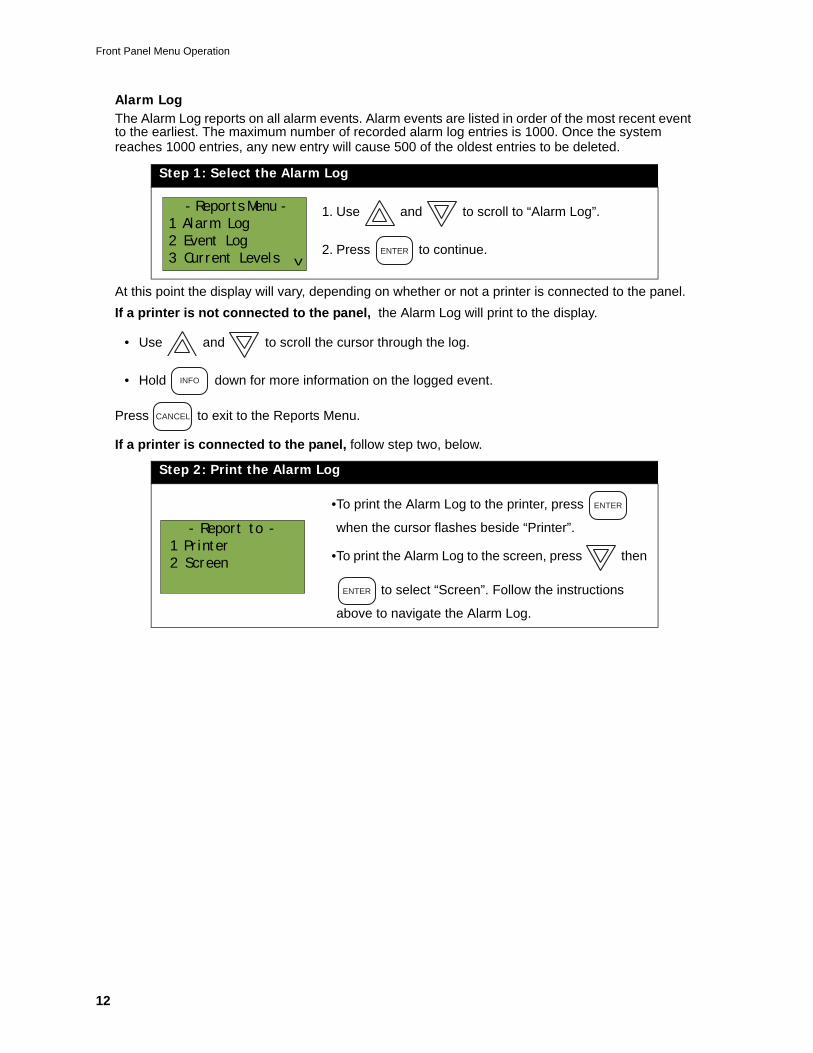
12
Alarm LogThe Alarm Log reports on all alarm events. Alarm events are listed in order of the most recent event to the earliest. The maximum number of recorded alarm log entries is 1000. Once the system reaches 1000 entries, any new entry will cause 500 of the oldest entries to be deleted.
At this point the display will vary, depending on whether or not a printer is connected to the panel.If a printer is not connected to the panel, the Alarm Log will print to the display.
• Use and to scroll the cursor through the log.
• Hold down for more information on the logged event.
Press to exit to the Reports Menu.
If a printer is connected to the panel, follow step two, below.
Step 1: Select the Alarm Log
1. Use and to scroll to “Alarm Log”.
2. Press to continue.
Step 2: Print the Alarm Log
•To print the Alarm Log to the printer, press
when the cursor flashes beside “Printer”.
•To print the Alarm Log to the screen, press then
to select “Screen”. Follow the instructions
above to navigate the Alarm Log.
- Reports Menu -
1 Alarm Log
2 Event Log
3 Current Levels
^ ENTER
INFO
CANCEL
- Report to -
1 Printer
2 Screen
ENTER
ENTER
Phase 2 FX-2000 User’s Guide
13
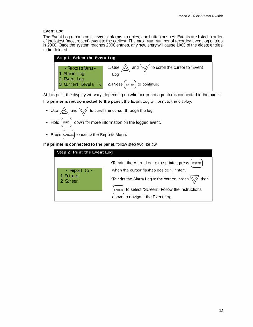
Event LogThe Event Log reports on all events: alarms, troubles, and button pushes. Events are listed in order of the latest (most recent) event to the earliest. The maximum number of recorded event log entries is 2000. Once the system reaches 2000 entries, any new entry will cause 1000 of the oldest entries to be deleted.
At this point the display will vary, depending on whether or not a printer is connected to the panel.If a printer is not connected to the panel, the Event Log will print to the display.
• Use and to scroll the cursor through the log.
• Hold down for more information on the logged event.
• Press to exit to the Reports Menu.
If a printer is connected to the panel, follow step two, below.
Step 1: Select the Event Log
1. Use and to scroll the cursor to “Event
Log”.
2. Press to continue.
Step 2: Print the Event Log
•To print the Alarm Log to the printer, press
when the cursor flashes beside “Printer”.
•To print the Alarm Log to the screen, press then
to select “Screen”. Follow the instructions
above to navigate the Event Log.
- Reports Menu -
1 Alarm Log
2 Event Log
3 Current Levels
^
ENTER
INFO
CANCEL
- Report to -
1 Printer
2 Screen
ENTER
ENTER
Front Panel Menu Operation
14
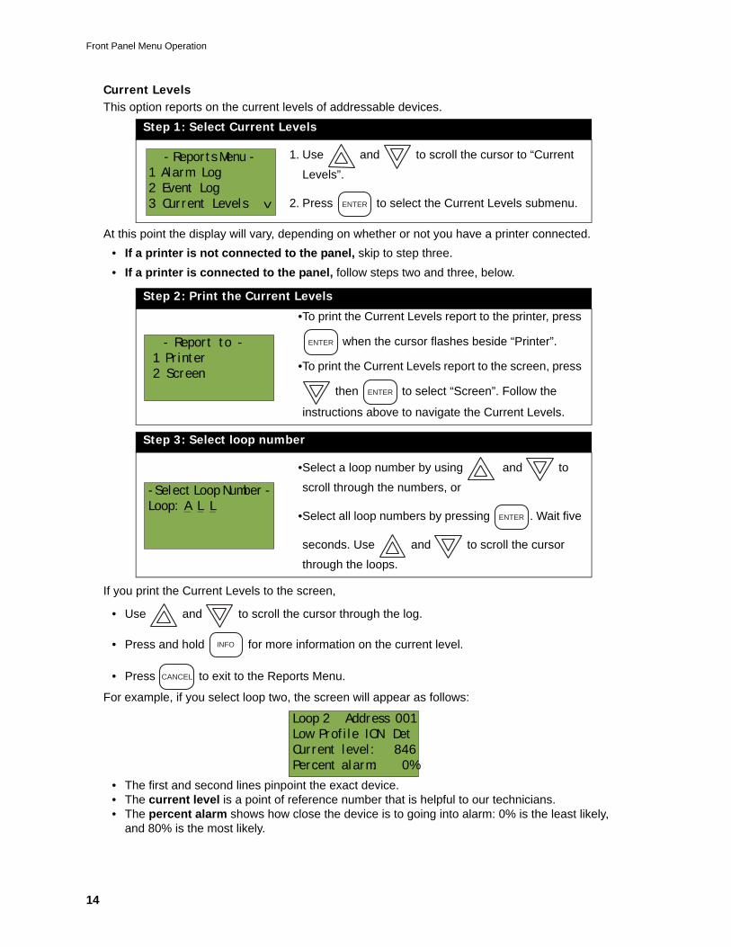
Current LevelsThis option reports on the current levels of addressable devices.
At this point the display will vary, depending on whether or not you have a printer connected.• If a printer is not connected to the panel, skip to step three.• If a printer is connected to the panel, follow steps two and three, below.
If you print the Current Levels to the screen,
• Use and to scroll the cursor through the log.
• Press and hold for more information on the current level.
• Press to exit to the Reports Menu.
For example, if you select loop two, the screen will appear as follows:
• The first and second lines pinpoint the exact device.• The current level is a point of reference number that is helpful to our technicians.• The percent alarm shows how close the device is to going into alarm: 0% is the least likely,
and 80% is the most likely.
Step 1: Select Current Levels
1. Use and to scroll the cursor to “Current
Levels”.
2. Press to select the Current Levels submenu.
Step 2: Print the Current Levels
•To print the Current Levels report to the printer, press
when the cursor flashes beside “Printer”.
•To print the Current Levels report to the screen, press
then to select “Screen”. Follow the
instructions above to navigate the Current Levels.
Step 3: Select loop number
•Select a loop number by using and to
scroll through the numbers, or
•Select all loop numbers by pressing . Wait five
seconds. Use and to scroll the cursor
through the loops.
- Reports Menu -
1 Alarm Log
2 Event Log
3 Current Levels
^
ENTER
- Report to -
1 Printer
2 Screen
ENTER
ENTER
-Select Loop Number -
Loop: A L LENTER
INFO
CANCEL
Loop 2 Address 001
Low Profile ION Det
Current level: 846
Percent alarm: 0%
Phase 2 FX-2000 User’s Guide
15
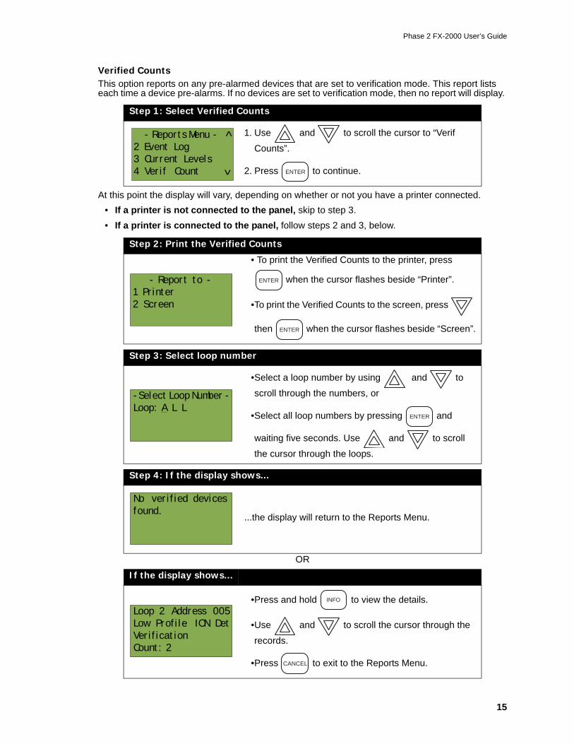
Verified CountsThis option reports on any pre-alarmed devices that are set to verification mode. This report lists each time a device pre-alarms. If no devices are set to verification mode, then no report will display.
At this point the display will vary, depending on whether or not you have a printer connected.• If a printer is not connected to the panel, skip to step 3.• If a printer is connected to the panel, follow steps 2 and 3, below.
Step 1: Select Verified Counts
1. Use and to scroll the cursor to “Verif
Counts”.
2. Press to continue.
Step 2: Print the Verified Counts
• To print the Verified Counts to the printer, press
when the cursor flashes beside “Printer”.
•To print the Verified Counts to the screen, press
then when the cursor flashes beside “Screen”.
Step 3: Select loop number
•Select a loop number by using and to
scroll through the numbers, or
•Select all loop numbers by pressing and
waiting five seconds. Use and to scroll
the cursor through the loops.
Step 4: If the display shows...
...the display will return to the Reports Menu.
OR
If the display shows...
•Press and hold to view the details.
•Use and to scroll the cursor through the
records.
•Press to exit to the Reports Menu.
- Reports Menu -
2 Event Log
3 Current Levels
4 Verif Count
^
^
ENTER
- Report to -
1 Printer
2 Screen
ENTER
ENTER
-Select Loop Number -
Loop: A L LENTER
No verified devices
found.
Loop 2 Address 005
Low Profile ION Det
Verification
Count: 2
INFO
CANCEL
Front Panel Menu Operation
16
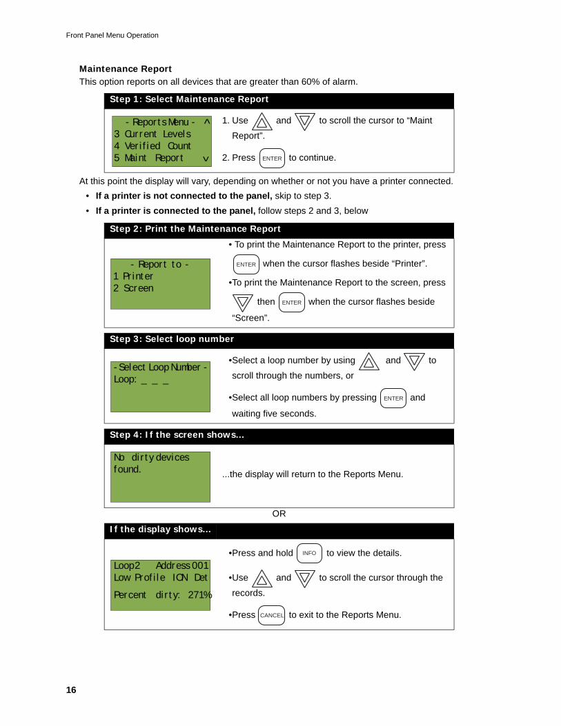
Maintenance ReportThis option reports on all devices that are greater than 60% of alarm.
At this point the display will vary, depending on whether or not you have a printer connected.• If a printer is not connected to the panel, skip to step 3.• If a printer is connected to the panel, follow steps 2 and 3, below
Step 1: Select Maintenance Report
1. Use and to scroll the cursor to “Maint
Report”.
2. Press to continue.
Step 2: Print the Maintenance Report
• To print the Maintenance Report to the printer, press
when the cursor flashes beside “Printer”.
•To print the Maintenance Report to the screen, press
then when the cursor flashes beside
“Screen”.
Step 3: Select loop number
•Select a loop number by using and to
scroll through the numbers, or
•Select all loop numbers by pressing and
waiting five seconds.
Step 4: If the screen shows...
...the display will return to the Reports Menu.
OR
If the display shows...
•Press and hold to view the details.
•Use and to scroll the cursor through the
records.
•Press to exit to the Reports Menu.
- Reports Menu -
3 Current Levels
4 Verified Count
5 Maint Report
^
^
ENTER
- Report to -
1 Printer
2 Screen
ENTER
ENTER
-Select Loop Number -
Loop: _ _ _
ENTER
No dirty devices
found.
Loop 2 Address 001
Low Profile ION Det
Percent dirty: 271%
INFO
CANCEL
Phase 2 FX-2000 User’s Guide
17
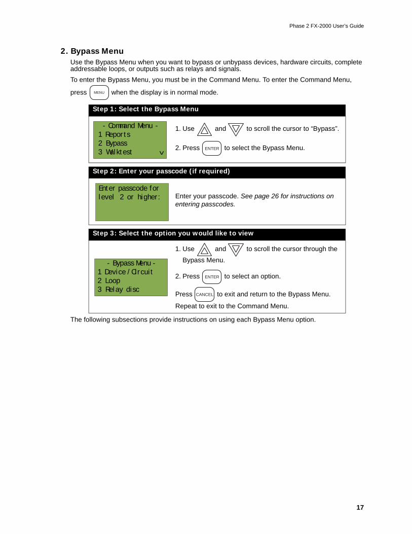
2. Bypass MenuUse the Bypass Menu when you want to bypass or unbypass devices, hardware circuits, complete addressable loops, or outputs such as relays and signals.To enter the Bypass Menu, you must be in the Command Menu. To enter the Command Menu,
press when the display is in normal mode.
The following subsections provide instructions on using each Bypass Menu option.
Step 1: Select the Bypass Menu
1. Use and to scroll the cursor to “Bypass”.
2. Press to select the Bypass Menu.
Step 2: Enter your passcode (if required)
Enter your passcode. See page 26 for instructions on entering passcodes.
Step 3: Select the option you would like to view
1. Use and to scroll the cursor through the
Bypass Menu.
2. Press to select an option.
Press to exit and return to the Bypass Menu.
Repeat to exit to the Command Menu.
MENU
- Command Menu -
1 Reports
2 Bypass
3 Walktest
^ ENTER
Enter passcode for
level 2 or higher:
- Bypass Menu -
1 Device /Circuit
2 Loop
3 Relay disc
ENTER
CANCEL
Front Panel Menu Operation
18
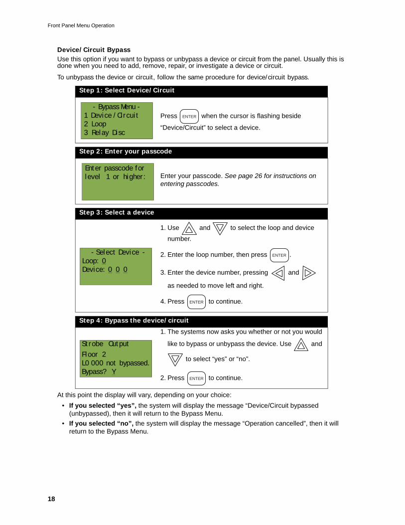
Device/Circuit BypassUse this option if you want to bypass or unbypass a device or circuit from the panel. Usually this is done when you need to add, remove, repair, or investigate a device or circuit.
To unbypass the device or circuit, follow the same procedure for device/circuit bypass.
At this point the display will vary, depending on your choice:• If you selected “yes”, the system will display the message “Device/Circuit bypassed
(unbypassed), then it will return to the Bypass Menu.• If you selected “no”, the system will display the message “Operation cancelled”, then it will
return to the Bypass Menu.
Step 1: Select Device/Circuit
Press when the cursor is flashing beside
“Device/Circuit” to select a device.
Step 2: Enter your passcode
Enter your passcode. See page 26 for instructions on entering passcodes.
Step 3: Select a device
1. Use and to select the loop and device
number.
2. Enter the loop number, then press .
3. Enter the device number, pressing and
as needed to move left and right.
4. Press to continue.
Step 4: Bypass the device/circuit
1. The systems now asks you whether or not you would
like to bypass or unbypass the device. Use and
to select “yes” or “no”.
2. Press to continue.
- Bypass Menu -
1 Device /Circuit
2 Loop
3 Relay Disc
ENTER
Enter passcode for
level 1 or higher:
- Select Device -
Loop: 0
Device: 0 0 0
ENTER
ENTER
Strobe Output
Floor 2
L0 000 not bypassed.
Bypass? YENTER
Phase 2 FX-2000 User’s Guide
19
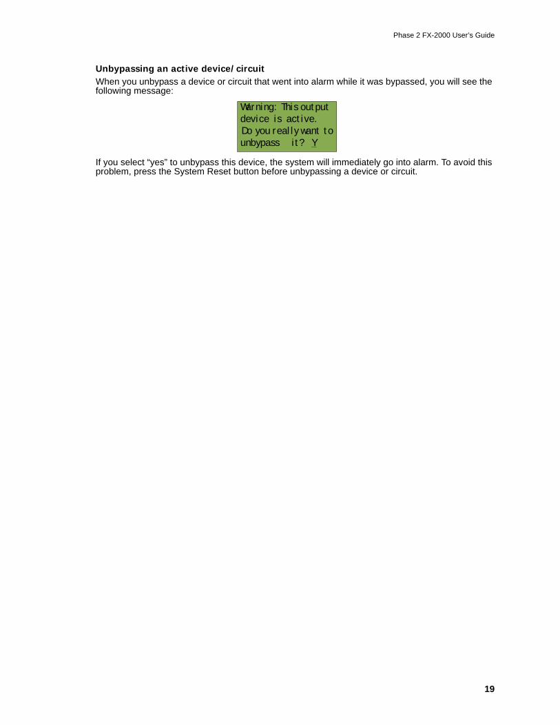
Unbypassing an active device/circuitWhen you unbypass a device or circuit that went into alarm while it was bypassed, you will see the following message:
If you select “yes” to unbypass this device, the system will immediately go into alarm. To avoid this problem, press the System Reset button before unbypassing a device or circuit.
Warning: This output
device is active.
Do you really want to
unbypass it? Y
Front Panel Menu Operation
20
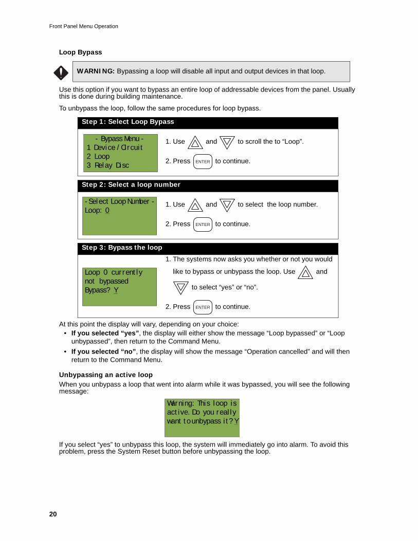
Loop Bypass
Use this option if you want to bypass an entire loop of addressable devices from the panel. Usually this is done during building maintenance.
To unbypass the loop, follow the same procedures for loop bypass.
At this point the display will vary, depending on your choice:• If you selected “yes”, the display will either show the message “Loop bypassed” or “Loop
unbypassed”, then return to the Command Menu.• If you selected “no”, the display will show the message “Operation cancelled” and will then
return to the Command Menu.
Unbypassing an active loopWhen you unbypass a loop that went into alarm while it was bypassed, you will see the following message:
If you select “yes” to unbypass this loop, the system will immediately go into alarm. To avoid this problem, press the System Reset button before unbypassing the loop.
WARNING: Bypassing a loop will disable all input and output devices in that loop.
Step 1: Select Loop Bypass
1. Use and to scroll the to “Loop”.
2. Press to continue.
Step 2: Select a loop number
1. Use and to select the loop number.
2. Press to continue.
Step 3: Bypass the loop
1. The systems now asks you whether or not you would
like to bypass or unbypass the loop. Use and
to select “yes” or “no”.
2. Press to continue.
- Bypass Menu -
1 Device /Circuit
2 Loop
3 Relay DiscENTER
-Select Loop Number -
Loop: 0
ENTER
Loop 0 currently
not bypassed
Bypass? Y
ENTER
Warning: This loop is
active. Do you really
want to unbypass it? Y
Phase 2 FX-2000 User’s Guide
21
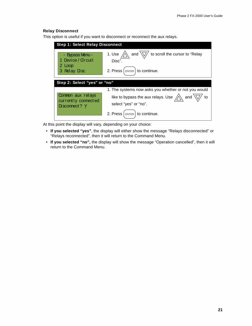
Relay DisconnectThis option is useful if you want to disconnect or reconnect the aux relays.
At this point the display will vary, depending on your choice:• If you selected “yes”, the display will either show the message “Relays disconnected” or
“Relays reconnected”, then it will return to the Command Menu.• If you selected “no”, the display will show the message “Operation cancelled”, then it will
return to the Command Menu.
Step 1: Select Relay Disconnect
1. Use and to scroll the cursor to “Relay
Disc”.
2. Press to continue.
Step 2: Select “yes” or “no”
1. The systems now asks you whether or not you would
like to bypass the aux relays. Use and to
select “yes” or “no”.
2. Press to continue.
- Bypass Menu -
1 Device /Circuit
2 Loop
3 Relay Disc ENTER
Common aux relays
currently connected
Disconnect? Y
ENTER
Front Panel Menu Operation
22
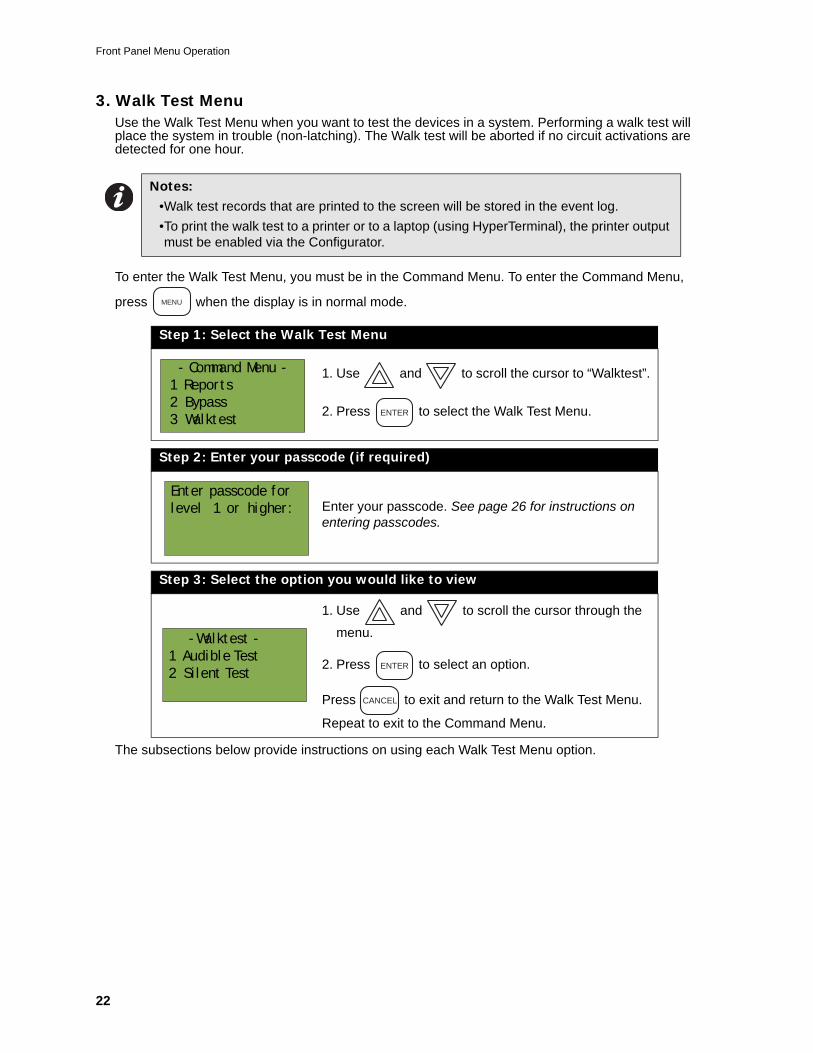
3. Walk Test MenuUse the Walk Test Menu when you want to test the devices in a system. Performing a walk test will place the system in trouble (non-latching). The Walk test will be aborted if no circuit activations are detected for one hour.
To enter the Walk Test Menu, you must be in the Command Menu. To enter the Command Menu,
press when the display is in normal mode.
The subsections below provide instructions on using each Walk Test Menu option.
Notes: •Walk test records that are printed to the screen will be stored in the event log.•To print the walk test to a printer or to a laptop (using HyperTerminal), the printer output must be enabled via the Configurator.
Step 1: Select the Walk Test Menu
1. Use and to scroll the cursor to “Walktest”.
2. Press to select the Walk Test Menu.
Step 2: Enter your passcode (if required)
Enter your passcode. See page 26 for instructions on entering passcodes.
Step 3: Select the option you would like to view
1. Use and to scroll the cursor through the
menu.
2. Press to select an option.
Press to exit and return to the Walk Test Menu.
Repeat to exit to the Command Menu.
MENU
- Command Menu -
1 Reports
2 Bypass
3 WalktestENTER
Enter passcode for
level 1 or higher:
- Walktest -
1 Audible Test
2 Silent TestENTER
CANCEL
Phase 2 FX-2000 User’s Guide
23
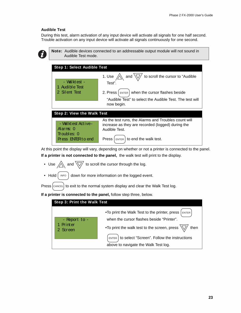
Audible TestDuring this test, alarm activation of any input device will activate all signals for one half second. Trouble activation on any input device will activate all signals continuously for one second.
At this point the display will vary, depending on whether or not a printer is connected to the panel.If a printer is not connected to the panel, the walk test will print to the display.
• Use and to scroll the cursor through the log.
• Hold down for more information on the logged event.
Press to exit to the normal system display and clear the Walk Test log.
If a printer is connected to the panel, follow step three, below.
Note: Audible devices connected to an addressable output module will not sound in Audible Test mode.
Step 1: Select Audible Test
1. Use and to scroll the cursor to “Audible
Test”.
2. Press when the cursor flashes beside
“Audible Test” to select the Audible Test. The test will now begin.
Step 2: View the Walk Test
As the test runs, the Alarms and Troubles count will increase as they are recorded (logged) during the Audible Test.
Press to end the walk test.
Step 3: Print the Walk Test
•To print the Walk Test to the printer, press
when the cursor flashes beside “Printer”.
•To print the walk test to the screen, press then
to select “Screen”. Follow the instructions
above to navigate the Walk Test log.
- Walktest -
1 Audible Test
2 Silent Test ENTER
- Walktest Active -
Alarms: 0
Troubles: 0
Press ENTER to end ENTER
INFO
CANCEL
- Report to -
1 Printer
2 Screen
ENTER
ENTER
Front Panel Menu Operation
24
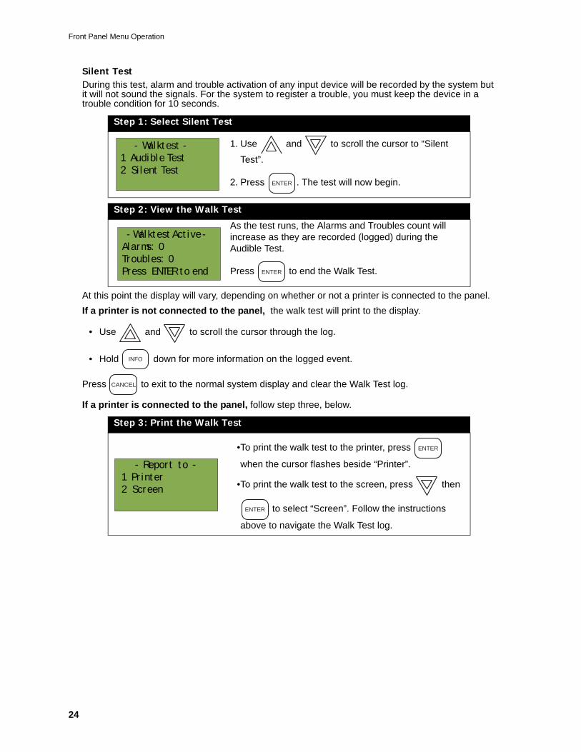
Silent TestDuring this test, alarm and trouble activation of any input device will be recorded by the system but it will not sound the signals. For the system to register a trouble, you must keep the device in a trouble condition for 10 seconds.
At this point the display will vary, depending on whether or not a printer is connected to the panel.If a printer is not connected to the panel, the walk test will print to the display.
• Use and to scroll the cursor through the log.
• Hold down for more information on the logged event.
Press to exit to the normal system display and clear the Walk Test log.
If a printer is connected to the panel, follow step three, below.
Step 1: Select Silent Test
1. Use and to scroll the cursor to “Silent
Test”.
2. Press . The test will now begin.
Step 2: View the Walk Test
As the test runs, the Alarms and Troubles count will increase as they are recorded (logged) during the Audible Test.
Press to end the Walk Test.
Step 3: Print the Walk Test
•To print the walk test to the printer, press
when the cursor flashes beside “Printer”.
•To print the walk test to the screen, press then
to select “Screen”. Follow the instructions
above to navigate the Walk Test log.
- Walktest -
1 Audible Test
2 Silent TestENTER
- Walktest Active -
Alarms: 0
Troubles: 0
Press ENTER to end ENTER
INFO
CANCEL
- Report to -
1 Printer
2 Screen
ENTER
ENTER
Phase 2 FX-2000 User’s Guide
25
Alternate Menu Option #3: Manual Control Enable
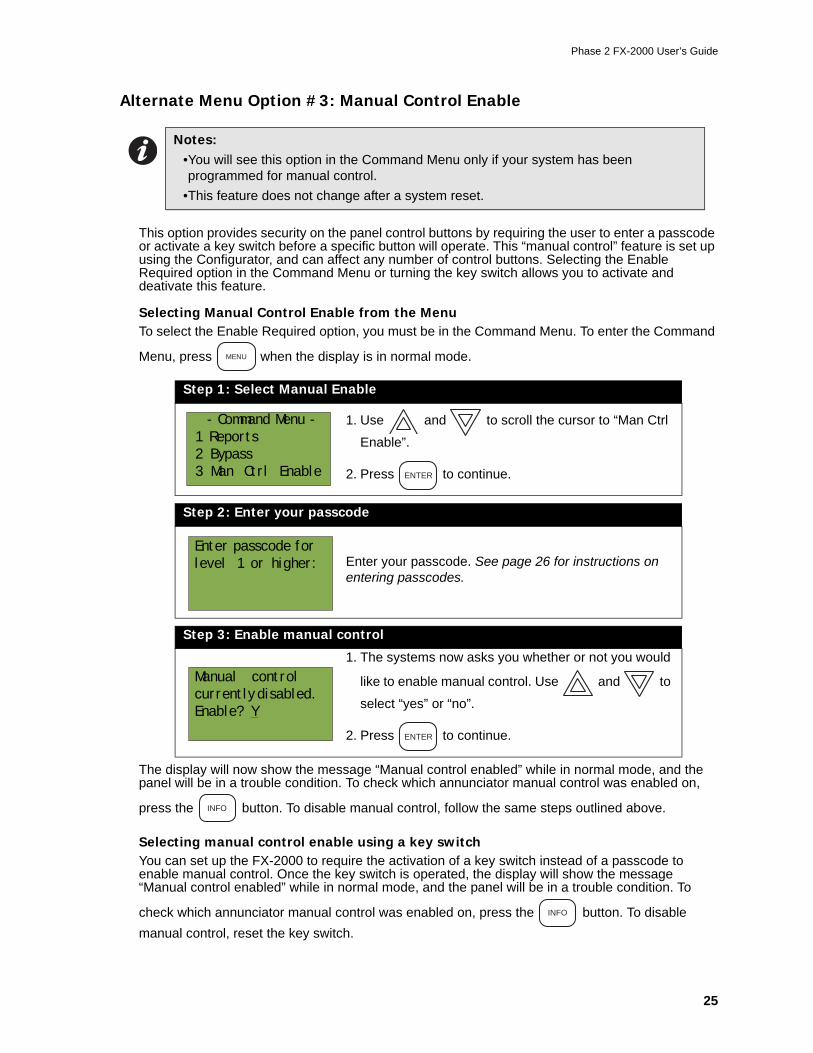
This option provides security on the panel control buttons by requiring the user to enter a passcode or activate a key switch before a specific button will operate. This “manual control” feature is set up using the Configurator, and can affect any number of control buttons. Selecting the Enable Required option in the Command Menu or turning the key switch allows you to activate and deativate this feature.
Selecting Manual Control Enable from the MenuTo select the Enable Required option, you must be in the Command Menu. To enter the Command
Menu, press when the display is in normal mode.
The display will now show the message “Manual control enabled” while in normal mode, and the panel will be in a trouble condition. To check which annunciator manual control was enabled on,
press the button. To disable manual control, follow the same steps outlined above.
Selecting manual control enable using a key switchYou can set up the FX-2000 to require the activation of a key switch instead of a passcode to enable manual control. Once the key switch is operated, the display will show the message “Manual control enabled” while in normal mode, and the panel will be in a trouble condition. To
check which annunciator manual control was enabled on, press the button. To disable manual control, reset the key switch.
Notes: •You will see this option in the Command Menu only if your system has been programmed for manual control.
•This feature does not change after a system reset.
Step 1: Select Manual Enable
1. Use and to scroll the cursor to “Man Ctrl
Enable”.
2. Press to continue.
Step 2: Enter your passcode
Enter your passcode. See page 26 for instructions on entering passcodes.
Step 3: Enable manual control
1. The systems now asks you whether or not you would
like to enable manual control. Use and to
select “yes” or “no”.
2. Press to continue.
MENU
- Command Menu -
1 Reports
2 Bypass
3 Man Ctrl Enable ENTER
Enter passcode for
level 1 or higher:
Manual control
currently disabled.
Enable? Y
ENTER
INFO
INFO
Front Panel Menu Operation
26
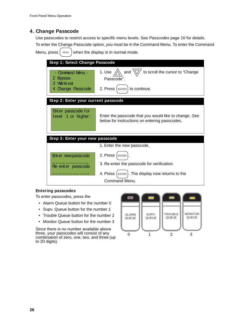
4. Change PasscodeUse passcodes to restrict access to specific menu levels. See Passcodes page 10 for details.To enter the Change Passcode option, you must be in the Command Menu. To enter the Command
Menu, press when the display is in normal mode.
Entering passcodesTo enter passcodes, press the
• Alarm Queue button for the number 0• Supv. Queue button for the number 1• Trouble Queue button for the number 2• Monitor Queue button for the number 3
Since there is no number available above three, your passcodes will consist of any combination of zero, one, two, and three (up to 20 digits).
Step 1: Select Change Passcode
1. Use and to scroll the cursor to “Change
Passcode”.
2. Press to continue.
Step 2: Enter your current passcode
Enter the passcode that you would like to change. See below for instructions on entering passcodes.
Step 3: Enter your new passcode
1. Enter the new passcode.
2. Press .
3. Re-enter the passcode for verification.
4. Press . The display now returns to the
Command Menu.
MENU
- Command Menu -
2 Bypass
3 Walktest
4 Change Passcode ENTER
Enter passcode for
level 1 or higher:
Enter new passcode
_ _ _ _ _ _ _ _ _ _ _
Re-enter passcode
_ _ _ _ _ _ _ _ _ _ _
ENTER
ENTER
ALARMQUEUE
SUPV.QUEUE
TROUBLEQUEUE
MONITORQUEUE
0 1 2 3
Phase 2 FX-2000 User’s Guide
27
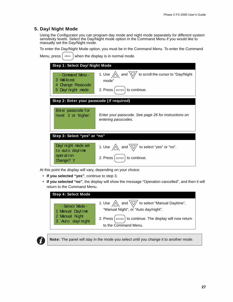
5. Day/Night ModeUsing the Configurator you can program day mode and night mode separately for different system sensitivity levels. Select the Day/Night mode option in the Command Menu if you would like to manually set the Day/Night mode.To enter the Day/Night Mode option, you must be in the Command Menu. To enter the Command
Menu, press when the display is in normal mode.
At this point the display will vary, depending on your choice:• If you selected “yes”, continue to step 3.• If you selected “no”, the display will show the message “Operation cancelled”, and then it will
return to the Command Menu.
Step 1: Select Day/Night Mode
1. Use and to scroll the cursor to “Day/Night
mode”
2. Press to continue.
Step 2: Enter your passcode (if required)
Enter your passcode. See page 26 for instructions on entering passcodes.
Step 3: Select “yes” or “no”
1. Use and to select “yes” or “no”.
2. Press to continue.
Step 4: Select Mode
1. Use and to select “Manual Daytime”,
“Manual Night”, or “Auto day/night”.
2. Press to continue. The display will now return
to the Command Menu.
Note: The panel will stay in the mode you select until you change it to another mode.
MENU
- Command Menu -
3 Walktest
4 Change Passcode
5 Day/night mode ENTER
Enter passcode for
level 2 or higher:
Day/night mode set
to auto daytime
operation
Change? YENTER
- Select Mode -
1 Manual Daytime
2 Manual Night
3 Auto day/nightENTER
Front Panel Menu Operation
28
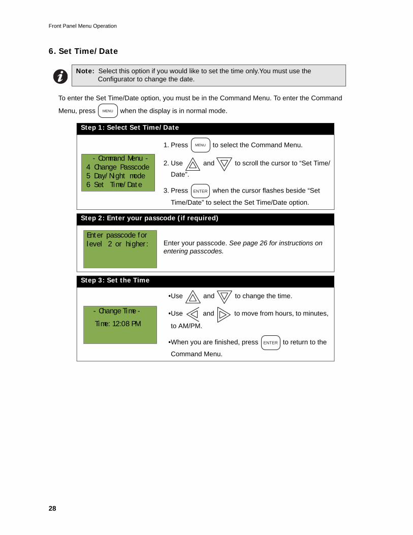
6. Set Time/Date
To enter the Set Time/Date option, you must be in the Command Menu. To enter the Command
Menu, press when the display is in normal mode.
Note: Select this option if you would like to set the time only.You must use the Configurator to change the date.
Step 1: Select Set Time/Date
1. Press to select the Command Menu.
2. Use and to scroll the cursor to “Set Time/
Date”.
3. Press when the cursor flashes beside “Set
Time/Date” to select the Set Time/Date option.
Step 2: Enter your passcode (if required)
Enter your passcode. See page 26 for instructions on entering passcodes.
Step 3: Set the Time
•Use and to change the time.
•Use and to move from hours, to minutes,
to AM/PM.
•When you are finished, press to return to the
Command Menu.
MENU
- Command Menu -
4 Change Passcode
5 Day/Night mode
6 Set Time/Date
MENU
ENTER
Enter passcode for
level 2 or higher:
- Change Time -
Time: 12:08 PM
ENTER
Phase 2 FX-2000 User’s Guide
29
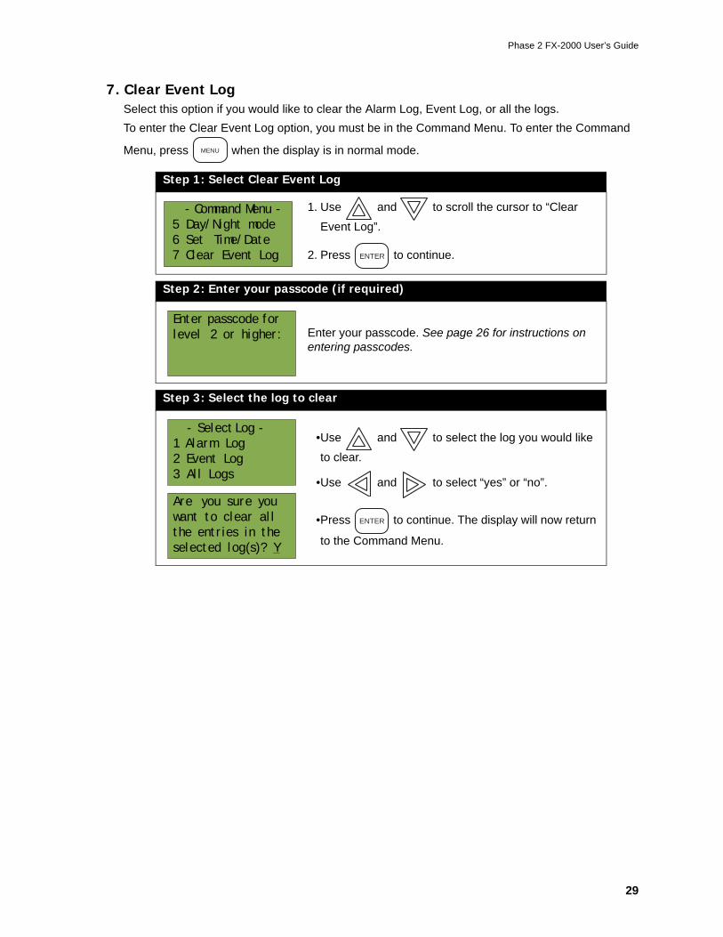
7. Clear Event LogSelect this option if you would like to clear the Alarm Log, Event Log, or all the logs.To enter the Clear Event Log option, you must be in the Command Menu. To enter the Command
Menu, press when the display is in normal mode.
Step 1: Select Clear Event Log
1. Use and to scroll the cursor to “Clear
Event Log”.
2. Press to continue.
Step 2: Enter your passcode (if required)
Enter your passcode. See page 26 for instructions on entering passcodes.
Step 3: Select the log to clear
•Use and to select the log you would like
to clear.
•Use and to select “yes” or “no”.
•Press to continue. The display will now return
to the Command Menu.
MENU
- Command Menu -
5 Day/Night mode
6 Set Time/Date
7 Clear Event Log ENTER
Enter passcode for
level 2 or higher:
- Select Log -
1 Alarm Log
2 Event Log
3 All Logs
Are you sure you
want to clear all
the entries in the
selected log(s)? Y
ENTER
Front Panel Menu Operation
30
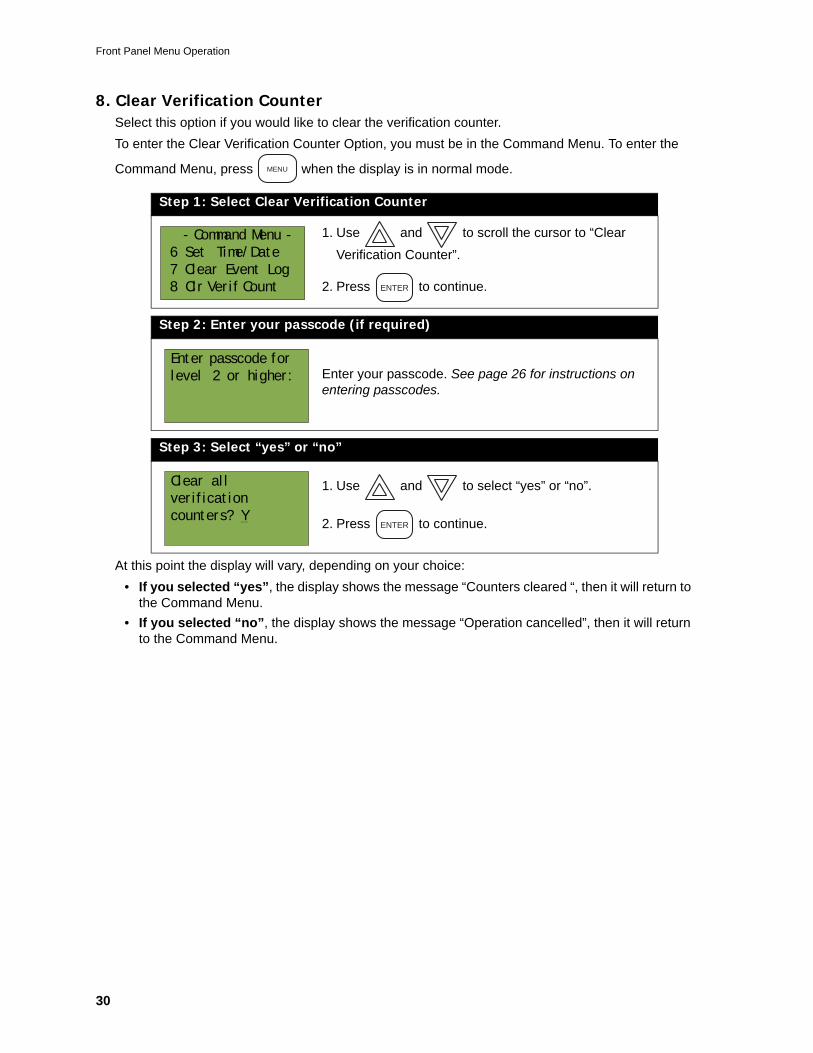
8. Clear Verification CounterSelect this option if you would like to clear the verification counter.To enter the Clear Verification Counter Option, you must be in the Command Menu. To enter the
Command Menu, press when the display is in normal mode.
At this point the display will vary, depending on your choice:• If you selected “yes”, the display shows the message “Counters cleared “, then it will return to
the Command Menu.• If you selected “no”, the display shows the message “Operation cancelled”, then it will return
to the Command Menu.
Step 1: Select Clear Verification Counter
1. Use and to scroll the cursor to “Clear
Verification Counter”.
2. Press to continue.
Step 2: Enter your passcode (if required)
Enter your passcode. See page 26 for instructions on entering passcodes.
Step 3: Select “yes” or “no”
1. Use and to select “yes” or “no”.
2. Press to continue.
MENU
- Command Menu -
6 Set Time/Date
7 Clear Event Log
8 Clr Verif Count ENTER
Enter passcode for
level 2 or higher:
Clear all
verification
counters? YENTER
Phase 2 FX-2000 User’s Guide
31
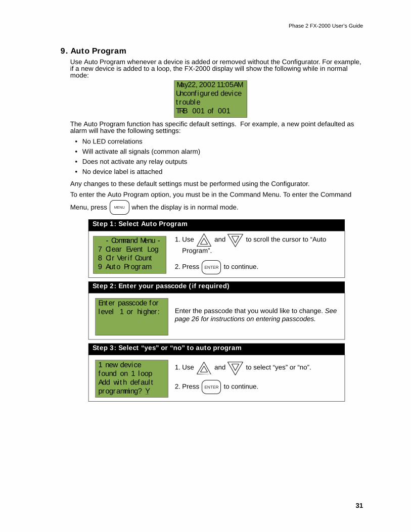
9. Auto ProgramUse Auto Program whenever a device is added or removed without the Configurator. For example, if a new device is added to a loop, the FX-2000 display will show the following while in normal mode:
The Auto Program function has specific default settings. For example, a new point defaulted as alarm will have the following settings:
• No LED correlations• Will activate all signals (common alarm)• Does not activate any relay outputs• No device label is attached
Any changes to these default settings must be performed using the Configurator.To enter the Auto Program option, you must be in the Command Menu. To enter the Command
Menu, press when the display is in normal mode.
Step 1: Select Auto Program
1. Use and to scroll the cursor to “Auto
Program”.
2. Press to continue.
Step 2: Enter your passcode (if required)
Enter the passcode that you would like to change. See page 26 for instructions on entering passcodes.
Step 3: Select “yes” or “no” to auto program
1. Use and to select “yes” or “no”.
2. Press to continue.
May22, 2002 11:05AM
Unconfigured device
trouble
TRB 001 of 001
MENU
- Command Menu -
7 Clear Event Log
8 Clr Verif Count
9 Auto Program ENTER
Enter passcode for
level 1 or higher:
1 new device
found on 1 loop
Add with default
programming? YENTER
Front Panel Menu Operation
32
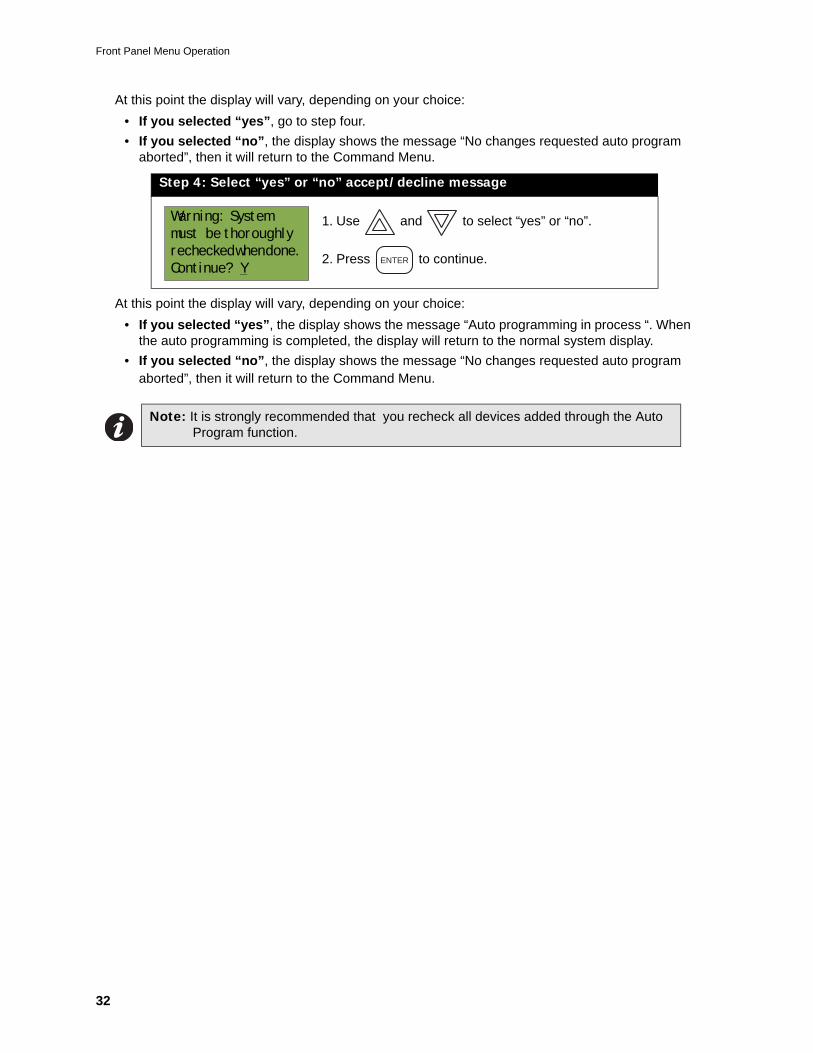
At this point the display will vary, depending on your choice:• If you selected “yes”, go to step four.• If you selected “no”, the display shows the message “No changes requested auto program
aborted”, then it will return to the Command Menu.
At this point the display will vary, depending on your choice:• If you selected “yes”, the display shows the message “Auto programming in process “. When
the auto programming is completed, the display will return to the normal system display.• If you selected “no”, the display shows the message “No changes requested auto program
aborted”, then it will return to the Command Menu.
Step 4: Select “yes” or “no” accept/decline message
1. Use and to select “yes” or “no”.
2. Press to continue.
Note: It is strongly recommended that you recheck all devices added through the Auto Program function.
Warning: System
must be thoroughly
rechecked when done.
Continue? YENTER

Notes

Notes


Canada25 Interchange WayVaughan, ON L4K 5W3Tel: 905-660-4655 Fax: 905-660-4113
Mircom 2004Printed in CanadaSubject to change without prior notice
U.S.A.4220 Steve Reynolds Blvd, Unit 17Norcross (Atlanta), GA 30093Tel: 1-888-660-4655 Fax: 1-888-660-4113 www.mircom.com
FX-2000 SeriesFire Alarm Control Panel
LT-XXX Rev. 1February 2004User's Guide
Advanced Life Safety Solutions Advanced Life Safety Solutions
FX-2000INTELLIGENT FIRE ALARM CONTROL
S UP V .QUE UE
P R E -ALAR M
Mircom FX-2000Fire Control System- System Normal -
Jan 01, 2000 12:21 AM
A.C. ON CPU FAULT GND FAULT
S IG NA LS IL E NC E
F IR EDR IL L
S Y S T E MR E S E T
G E NE R A LA L A R M
G E NE R A LA L A R M
L A MPT E S T
ENTER
ALARMQUEUE
SUPV.QUEUE
TROUBLEQUEUE
MONITORQUEUE
MENU
CANCEL
INFO