Embed Size (px)
Citation preview

Configuration Guide
Fire Alarm Control Panel
LT-1148 Rev. 5October 2018
FX-3500/FX-3500RCU

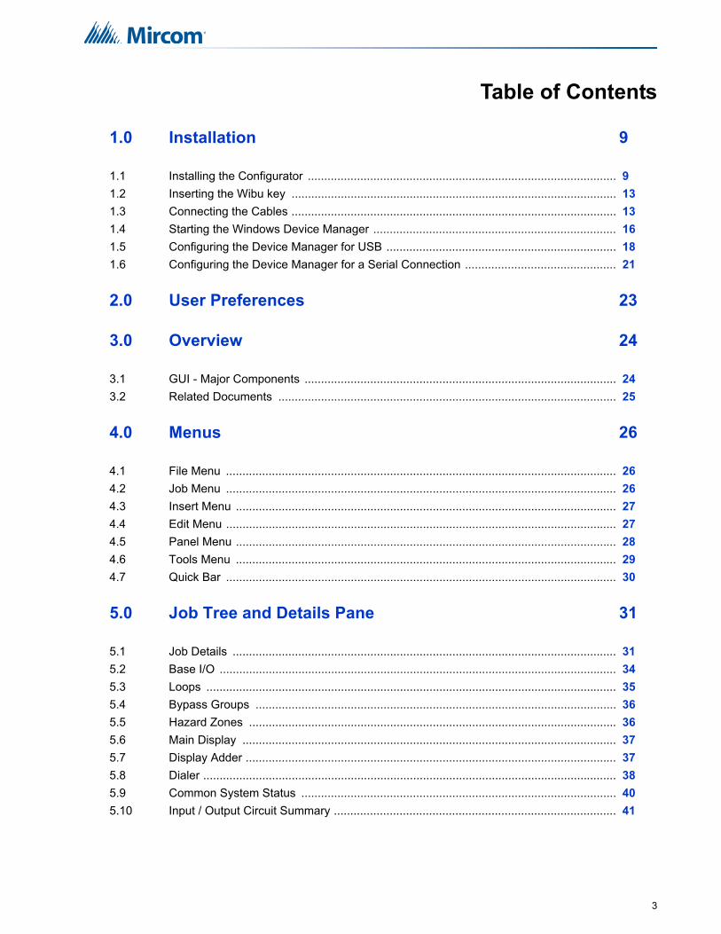
Table of Contents
1.0 Installation 9
1.1 Installing the Configurator .............................................................................................. 9
1.2 Inserting the Wibu key ................................................................................................... 13
1.3 Connecting the Cables ................................................................................................... 13
1.4 Starting the Windows Device Manager .......................................................................... 16
1.5 Configuring the Device Manager for USB ...................................................................... 18
1.6 Configuring the Device Manager for a Serial Connection .............................................. 21
2.0 User Preferences 23
3.0 Overview 24
3.1 GUI - Major Components ............................................................................................... 24
3.2 Related Documents ....................................................................................................... 25
4.0 Menus 26
4.1 File Menu ....................................................................................................................... 26
4.2 Job Menu ....................................................................................................................... 26
4.3 Insert Menu .................................................................................................................... 27
4.4 Edit Menu ....................................................................................................................... 27
4.5 Panel Menu .................................................................................................................... 28
4.6 Tools Menu .................................................................................................................... 29
4.7 Quick Bar ....................................................................................................................... 30
5.0 Job Tree and Details Pane 31
5.1 Job Details ..................................................................................................................... 31
5.2 Base I/O ......................................................................................................................... 34
5.3 Loops ............................................................................................................................. 35
5.4 Bypass Groups .............................................................................................................. 36
5.5 Hazard Zones ................................................................................................................ 36
5.6 Main Display .................................................................................................................. 37
5.7 Display Adder ................................................................................................................. 37
5.8 Dialer .............................................................................................................................. 38
5.9 Common System Status ................................................................................................ 40
5.10 Input / Output Circuit Summary ...................................................................................... 41
3

Table of Contents
6.0 Adding Items to the Job 42
6.1 Add Loop Controllers ..................................................................................................... 42
6.2 Add Annunciator ............................................................................................................. 42
6.3 Add Correlations ............................................................................................................ 42
6.4 Add Device ..................................................................................................................... 43
6.5 Add Display Adder ......................................................................................................... 44
6.6 Deleting Correlations ...................................................................................................... 45
6.7 Hazard Zones ................................................................................................................. 45
7.0 Managing the Database 48
7.1 Backup Database ........................................................................................................... 48
7.2 Restore Database .......................................................................................................... 48
7.3 Compact Database ........................................................................................................ 50
8.0 Managing Jobs 51
8.1 Create a New Job .......................................................................................................... 51
8.2 Open Job ........................................................................................................................ 52
8.3 Import Job ...................................................................................................................... 52
8.4 Export Job ...................................................................................................................... 53
8.5 New Version ................................................................................................................... 54
8.6 Delete Job Version ......................................................................................................... 54
8.7 Version History ............................................................................................................... 54
8.8 Compare Job Versions ................................................................................................... 55
8.9 Validate Job ................................................................................................................... 58
8.10 Edit Job .......................................................................................................................... 58
9.0 Working with the Panel 59
9.1 Connect .......................................................................................................................... 59
9.2 Send Job ........................................................................................................................ 60
9.3 Get Job ........................................................................................................................... 60
9.4 Panel Information ........................................................................................................... 60
9.5 Event Log ....................................................................................................................... 61
9.6 Upgrade Firmware ......................................................................................................... 62
10.0 Tools Menu 63
10.1 Extract All DB ................................................................................................................. 63
10.2 Validate All ..................................................................................................................... 63
10.3 Build Job ........................................................................................................................ 63
10.4 Build Job Old Versions ................................................................................................... 63
4

Table of Contents
10.5 Link Statistics ................................................................................................................. 63
10.6 Log Send ........................................................................................................................ 63
10.7 Log Get .......................................................................................................................... 63
10.8 Log Comms .................................................................................................................... 63
10.9 Trace .............................................................................................................................. 64
10.10 Display Structure ............................................................................................................ 64
10.11 External Bus ................................................................................................................... 64
10.12 About MGC-3000 Series Configuration Utility ................................................................ 64
10.13 Paste Special - Circuits, Adders or Entire Loops ........................................................... 65
10.14 Paste Special - Display Items, Display Adders or Annunciators .................................... 65
11.0 Correlations Pane 67
11.1 Input Circuit Correlations ............................................................................................... 67
11.2 Output Circuit Correlations ............................................................................................. 67
12.0 Differences Mode / Differences Report 68
12.1 Introduction .................................................................................................................... 68
12.2 Primary vs. Secondary Job ............................................................................................ 68
12.3 Initiating Differences Mode ............................................................................................ 68
13.0 Printing 70
13.1 Print Setup ..................................................................................................................... 72
5

List of Figures
Figure 1 FTDIChip CDM Drivers .................................................................................................. 9
Figure 2 Device Driver Installation Wizard ................................................................................... 10
Figure 3 Completing the Device Driver Installation Wizard .......................................................... 10
Figure 4 MGC-3000 Series Configuration Utility InstallShield Wizard .......................................... 11
Figure 5 License Agreement ........................................................................................................ 11
Figure 6 Choose Destination Location ......................................................................................... 12
Figure 7 InstallShield Wizard Complete ....................................................................................... 12
Figure 8 Security Key Logon ........................................................................................................ 13
Figure 9 Picture of FX-3500 board showing USB Port ................................................................. 14
Figure 10 Picture of FX-3500 board showing Configurator Port .................................................... 15
Figure 11 Windows 8 Search screen ............................................................................................. 16
Figure 12 System Properties .......................................................................................................... 17
Figure 13 Device Manager ............................................................................................................. 18
Figure 14 Microsoft Serial Ballpoint ................................................................................................ 18
Figure 15 Microsoft Serial Ballpoint Disabled ................................................................................. 18
Figure 16 USB Serial Port in the Device Manager ......................................................................... 19
Figure 17 USB Serial Port Properties ............................................................................................. 19
Figure 18 Port Settings ................................................................................................................... 20
Figure 19 Advanced Settings ......................................................................................................... 20
Figure 20 COM Port in the Device Manager .................................................................................. 21
Figure 21 Communications Port Properties ................................................................................... 21
Figure 22 Port Settings ................................................................................................................... 22
Figure 23 Advanced Settings ......................................................................................................... 22
Figure 24 User Preferences window .............................................................................................. 23
Figure 25 GUI Panels ..................................................................................................................... 24
Figure 26 Job Details ..................................................................................................................... 31
Figure 27 Holidays Window ............................................................................................................ 33
Figure 28 Base I/O Details ............................................................................................................. 35
Figure 29 Add Correlations Window ............................................................................................... 42
Figure 30 Add Devices window ...................................................................................................... 43
Figure 31 Add Display Adder window ............................................................................................ 44
Figure 32 Change process type warning ........................................................................................ 45
Figure 33 Backup Database ........................................................................................................... 48
Figure 34 Restore Database .......................................................................................................... 49
Figure 35 Restore Database .......................................................................................................... 49
Figure 36 Create Job window ......................................................................................................... 51
Figure 37 Select Job and Version window ..................................................................................... 52
Figure 38 Import Job window ......................................................................................................... 52
Figure 39 Export Job window ......................................................................................................... 53
Figure 40 Version History window .................................................................................................. 54
Figure 41 Select Job to Compare window ...................................................................................... 55
Figure 42 Advanced Compare Options window ............................................................................. 57
Figure 43 The job is protected against unintentional edits ............................................................. 58
6

List of Figures
Figure 44 This job version has already been built or downloaded to the panel ............................. 58
Figure 45 Connection window ........................................................................................................ 59
Figure 46 Upgrade Firmware Wizard ............................................................................................. 62
Figure 47 Upgrade Firmware Wizard ............................................................................................. 62
Figure 48 Paste Special ................................................................................................................. 65
Figure 49 Paste Special ................................................................................................................. 65
Figure 50 Correlations Pane .......................................................................................................... 67
Figure 51 Differences ..................................................................................................................... 69
Figure 52 Print ................................................................................................................................ 70
Figure 53 Print Setup ..................................................................................................................... 72
7

8
List of Tables
Table 1 File Menu ....................................................................................................................... 26
Table 2 Job Menu ....................................................................................................................... 26
Table 3 Insert Menu .................................................................................................................... 27
Table 4 Edit Menu ....................................................................................................................... 28
Table 5 Panel Menu .................................................................................................................... 28
Table 6 Tools Menus ................................................................................................................... 29
Table 7 Quick Bar Icons .............................................................................................................. 30
Table 8 Timers ............................................................................................................................ 33
Table 9 Loop Details ................................................................................................................... 35
Table 10 Flag Columns - F1, F2, F3 ............................................................................................. 36
Table 11 Bypass Groups ............................................................................................................... 36
Table 12 Display Adder Info .......................................................................................................... 37

1.0 InstallationYou need the following items in order to install the Configurator and connect it to the FX-3500:
• Windows computer with a serial port, USB port, or modem.
• One of the following sets of cables:
• UIMA cable and serial cable.
• USB cable.
• Telephone cable.
• Registered Wibu key.
• MGC-3000 Series Configuration Utility (the Configurator).
To connect the Configurator to the Fire Alarm Control Panel you must:
• Install the Configurator.
• Insert the Wibu key.
• Connect the cables.
• Configure Windows.
• Start the Configurator.
Follow the instructions below to complete these steps.
1.1 Installing the Configurator
Follow these instructions to install the Configurator and connect to the FX-3500.
1. Start the Configurator installer:
• If you have Windows 7 or Windows 8, right-click the MGC-3000_Config icon, and then click Run as Administrator.
• If you have Windows XP, double-click the MGC-3000_Config icon.
The FTDIChip CDM Drivers installer starts. These drivers are necessary for communication with the FX-3500.
Figure 1 FTDIChip CDM Drivers
9

Installation
2. Click Extract.
The Device Driver Installation Wizard starts.
Figure 2 Device Driver Installation Wizard
3. Click Next.
The wizard installs the drivers, and then the Completing the Device Driver Installation Wizard appears.
Figure 3 Completing the Device Driver Installation Wizard
10

Installation
4. Click Finish.
The MGC-3000 Series Configuration Utility InstallShield Wizard starts.
Figure 4 MGC-3000 Series Configuration Utility InstallShield Wizard
5. Click Next.
6. The License Agreement window appears.
Figure 5 License Agreement
11

Installation
7. Click Yes to accept the agreement.
The Choose Destination Location window appears.
Figure 6 Choose Destination Location
8. Click Next to install the software in the recommended location.
The InstallShield Wizard Complete window appears.
Figure 7 InstallShield Wizard Complete
12

Installation
9. Click Finish.
1.2 Inserting the Wibu key
1. Insert your Wibu key into the computer.
If a Security Key Logon window appears, you must contact your ESD Administrator or Mircom technical support to upgrade your key. Otherwise, you might not be able to connect to the FX-3500.
Figure 8 Security Key Logon
1.3 Connecting the Cables
• If you are using a USB cable, go to section 1.3.1 below.
• If you are using a UIMA cable and a serial cable, go to section 1.3.2 on page 15.
• If you are using a telephone cable and modem, go to section 1.3.3 on page 15.
13

Installation
1.3.1 If you have a USB cable:
1. Connect the USB end of the serial to USB cable to a USB port on the computer.
2. Connect the other end of the USB cable to port P13 on the FX-3500. It is labeled USB PORT.
Figure 9 Picture of FX-3500 board showing USB Port
3. Go to section 1.4 Starting the Windows Device Manager on page 16.
Attention: If you connect more than one FX-3500 panel to the same computer over USB, always use the same physical USB port on the computer. Otherwise, every time that you connect a panel to a different port, you must complete the steps in section 1.5 below.
In addition, if you connect more than one FX-3500 panel to the same computer, do not use a USB 3 port. Otherwise, every time that you connect a new panel to the USB 3 port, you must complete the steps in section 1.5 below.
!
P13
USB PORT
14

Installation
1.3.2 If you are using a UIMA cable and a serial cable
1. Connect the serial to serial cable to the UIMA cable.
2. Connect the 10-pin head of the UIMA cable to port P5 on the FX-3500. It is labeled To PC Configurator. See Figure 10.
Figure 10 Picture of FX-3500 board showing Configurator Port
3. Connect the other end of the serial cable to a serial port on the computer.
4. Go to section 1.4 Starting the Windows Device Manager below.
1.3.3 If you are using a telephone cable
1. Connect the telephone cable to the modem that is connected to your computer.
2. Wire the FX-3500 to the public telephone switch. See the Dialer Wiring section of the FX-3500 Installation Manual and the FX-3500RCU Installation Manual.
3. Go to chapter 2.0 User Preferences on page 23.
P5
To PC Configurator
15
Installation
1.4 Starting the Windows Device Manager
• To start the Device Manager, follow the instructions below for your version of Windows.
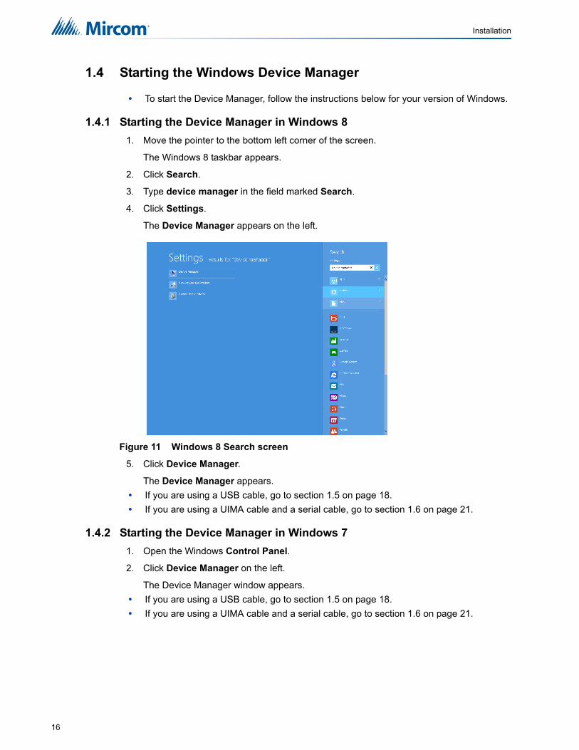
1.4.1 Starting the Device Manager in Windows 8
1. Move the pointer to the bottom left corner of the screen.
The Windows 8 taskbar appears.
2. Click Search.
3. Type device manager in the field marked Search.
4. Click Settings.
The Device Manager appears on the left.
Figure 11 Windows 8 Search screen
5. Click Device Manager.
The Device Manager appears.
• If you are using a USB cable, go to section 1.5 on page 18.
• If you are using a UIMA cable and a serial cable, go to section 1.6 on page 21.
1.4.2 Starting the Device Manager in Windows 7
1. Open the Windows Control Panel.
2. Click Device Manager on the left.
The Device Manager window appears.
• If you are using a USB cable, go to section 1.5 on page 18.
• If you are using a UIMA cable and a serial cable, go to section 1.6 on page 21.
16

Installation
1.4.3 Starting the Device Manager in Windows XP
1. Open the Windows Control Panel.
2. Click System.
If you do not see System, click Switch to Classic View on the left.
The System Properties window appears.
Figure 12 System Properties
3. Click the Hardware tab, and then click Device Manager.
The Device Manager window appears.
• If you are using a USB cable, go to section 1.5 on page 18.
• If you are using a UIMA cable and a serial cable, go to section 1.6 on page 21.
17

Installation
1.5 Configuring the Device Manager for USB
1. In the Device Manager, click the plus sign (+) or arrow ( ) beside Mice and other pointing devices.
Figure 13 Device Manager
2. Right-click Microsoft Serial Ballpoint, and then click Disable in the pulldown menu.
A window appears warning that disabling this device will cause it to stop functioning.
3. Click Yes.
Figure 14 Microsoft Serial Ballpoint
An X (a downward pointing arrow in Windows 8) appears over the Microsoft Serial Ballpoint, showing that is it disabled.
Figure 15 Microsoft Serial Ballpoint Disabled
Attention: If you connect more than one FX-3500 panel to the same computer over USB, always use the same physical USB port on the computer. Otherwise, every time that you connect a panel to a different port, you must complete the steps in this section.
In addition, if you connect more than one FX-3500 panel to the same computer, do not use a USB 3 port. Otherwise, every time that you connect a new panel to the USB 3 port, you must complete the steps in this section.
!
18

Installation
4. In the Device Manager window, click the plus sign (+) or arrow ( ) beside Ports.
Figure 16 USB Serial Port in the Device Manager
5. Right-click USB Serial Port, and then click Properties in the pulldown menu.
If there is more than one USB Serial Port, click the one that you are using to connect to the FX-3500.
The USB Serial Port Properties window appears.
Figure 17 USB Serial Port Properties
19

Installation
6. Click the Port Settings tab.
The Port Settings window appears.
Figure 18 Port Settings
7. Click Advanced.
The Advanced Settings window appears.
Figure 19 Advanced Settings
8. Click the pulldown menu beside Receive (Bytes), and then click 64.
9. Click the pulldown menu beside Transmit (Bytes), and then click 64.
10. Click the pulldown menu beside Latency Timer (msec), and then click 1.
11. Uncheck the checkbox beside Serial Emulator.
12. Click OK to close the Advanced Settings window.
13. Click OK to close the USB Serial Port Properties window, and then close the Device Manager window.
14. Double-click the MGC-3000 Series Configurator Utility icon on the desktop to start the Configurator.
15. Go to chapter 2.0 User Preferences on page 23.
8.9.
10.11.
20

Installation
1.6 Configuring the Device Manager for a Serial Connection
1. In the Device Manager window, click the plus sign (+) or arrow ( ) beside Ports.
Figure 20 COM Port in the Device Manager
2. Right-click the COM communications port, and then click Properties in the pulldown menu. It is usually labeled Communications Port (COM1).
If there is more than one COM communications port, click the one that you are using to connect to the FX-3500.
The Communications Port Properties window appears.
Figure 21 Communications Port Properties
21

Installation
3. Click the Port Settings tab.
The Port Settings window appears.
Figure 22 Port Settings
4. Click Advanced.
The Advanced Settings window appears.
Figure 23 Advanced Settings
5. Drag the slider beside Receive Buffer to the far left.
6. Drag the slider beside Transmit Buffer to the far left.
7. Click OK to close the Advanced Settings window.
8. Click OK to close the Communications Port Properties window, and then close the Device Manager window.
9. Double-click the MGC-3000 Series Configurator Utility icon on the desktop to start the Configurator.
10. Go to chapter 2.0 User Preferences on page 23.
22

2.0 User PreferencesThe first time the Configurator starts, the User Preferences window appears.
Figure 24 User Preferences window
These values are stored in the registry (per Configurator version) so that a returning user operates in the same folders, etc.
On the first execution of the Configurator this dialog is popped up automatically to establish these values. It can be used at any time thereafter to change the settings.
User Name used for the Author of all new jobs and job versions
Serial Port designates which COM port (or USB pseudo COM port) the Configurator will use to connect to the panel. To accommodate machines with multiple (pseudo) COM ports, the list will be extended. It currently only shows serial ports COM1-COM4
Security Key port - Lists the ports where a Wibu key can be inserted. The Wibu key is required.
BDM Port designates which parallel port the Background Debugging Module will use (for those products that support this interface).
Database Folder specifies where the main Configurator.mdb database file resides. Usually the folder where the Configurator is installed.
Job Edit Folder specifies where individual job files are extracted to/imported from.
Job Build Folder specifies where the 'C' file output files are written by Job Validate and other trace or debug facilities.
Backup Folder specifies where backup database files are written to and restored from.
Show Tools Menu display or hide an additional Tools menu. This menu contains trace and debug facilities and some features that Technical Support may require a user to turn on to gather diagnostic information.
Keep Only Latest Versions After Backup
if enabled, only the latest versions of all jobs will be kept after a successful Backup Database command, all older versions are removed from the current database.
23

3.0 OverviewIn order to operate as a fire alarm, a fire alarm panel must be loaded with firmware and configuration data. A set of configuration data, used to uniquely describe and control a given set of hardware, is called a Job. The Configurator allows the user to create and manage jobs. It also allows the user to send firmware to a panel and all its related nodes and CPUs.
The Configurator is typically run on a portable notebook or laptop computer that is taken to the job site and connected to the panel. The technician prepares a job using the Configurator’s Graphical User Interface (GUI). The job can then be sent to the panel. The same or a different authorised technician can later retrieve the job from the panel, modify it and send it back.
The job repository is a Relational Database (MS-Access). Jobs can be imported or merged from another database, copied, deleted, and archived in various formats. A job can be printed, or two versions of a job can be compared.
A wizard driven program installs the product. On the first use of the Configurator the user is prompted for the paths and file names where jobs, backup, the database, etc. are to be stored. Registry entries remember many of the user’s preferences.
The configuration software runs on a Personal Computer (PC) and the jobs can be transferred to the panel in one of three ways. Jobs can be transferred through a USB connection directly to the panel from the PC, through a Universal Interface Module Adapter (UIMA) connection from the PC serial port to the 10 pin P5 port on the main board, or remotely using a dial-up modem to connect to the on-board dialer.
3.1 GUI - Major Components
The Configurator uses a familiar Microsoft Windows Graphical User Interface (GUI) to present a job. The screen is divided into (max.) three panes.
Figure 25 GUI Panels
JOB TREE
DETAILS
CORRELATIONS
24

Overview
3.1.1 Job Tree
On the left of the screen, the job is represented as a tree, similar to a file explorer. At the highest level in the tree are the CPUs or Nodes. Under each node are its components - Annunciators, Loop Controllers, etc. Some items are further subdivided, for example, an annunciator into display adders and a loop controller into loops.
Some items in the tree do not directly represent a physical component. For example, tree nodes exist for input and output summaries and for common controls.
3.1.2 Details
The top right pane is used to display the details of the currently selected tree node. This can be a form view or a list view. For example, this pane is used to list the devices on a loop controller (list view) and to display the options and messages of a main display (form view).
3.1.3 Correlations
The third, bottom right pane is used to show correlations from an item selected in the top right pane, where appropriate. For example, when a loop is selected in the tree, the top right pane would show all of its devices or circuits. When one or more input circuits are selected in the list, then the bottom pane would show the output circuit(s) to which this is correlated.
A standard (File, Edit, etc.) and specialized (Job, Panel, Tools) menu hierarchy is provided for such functions at Create New Job, Delete Job, Connect to Panel, etc.
A tool bar provides convenient short cuts to the more frequently used functions
Standard keyboard short cuts and mouse operations are supported for such things as copy and paste, drag and drop, etc.
3.2 Related Documents
For information on releasing applications for the FX-3500RCU, see the latest version of LT-1091 FX-3500RCU Releasing Application Guide on http://www.mircom.com.
25

4.0 Menus4.1 File Menu
The File Menu contains the following commands:
4.2 Job Menu
The Job Menu contains the following commands:
Table 1 File Menu
Name Short cut Description
Backup Database
Backup database makes a copy of the Master Database in the File folder specified in the User. The backup file will have a name of the form YYYY-MM-DD.mdb. The back up can be used by the Restore Database command to recover all of the jobs in the database. It can also use the Import command to recover selected jobs. Backup your Master Database often and store a copy of the resulting file on a CD or other media.
Restore Database
Restores the backup database to the active database directory for use or modification. This will overwrite the existing database and will return the database to the date the backup was made.
Compact Database
To ensure optimal performance, you should compact and repair your database on a regular basis. If you have purged job versions or deleted jobs, Compacting the Database will regain the space occupied by those records.
User Preferences
Specifies User Preferences, such as the location of database, backups, job files, etc.
Ctrl+P
Print the active job.
Print Preview Display a Print Preview of the active job.
Print Setup Select the printer, paper size and orientation for a print job.
Exit Closes the Configurator.
Table 2 Job Menu
Name Short cut Description
New Job
Ctrl+N;
This command will open the Create Job dialog which will allow you to start a new job. The new job can be based on a supplied template or on an existing job.
Open Job
Ctrl+O
This command will open an existing job from your database.
26

Menus
4.3 Insert Menu
The Insert Menu contains the following commands.
Some commands may be disabled (greyed) depending on what items are selected on the user interface.
4.4 Edit Menu
The Edit Menu contains the following commands.
Import Job Imports a selected job/version from an external database or serialized job archive and converts the job to the current version if necessary.
Export JobCtrl+E
Exports the current job in one of two formats: A single job database file, or a compact, serialized archive format.
New Version
Ctrl+W
Make a copy of the current job, assigning it the next highest version number. The user is prompted for mandatory comments and may also override the Author field. The Job Name cannot be changed. The new version is un-locked for editing.
Delete Job Version
Ctrl+DThis command permanently deletes the current Job / Job Version from the database
Version History
Display the Version History (Date, Author, Comments) for the current job.
Compare Job Versions
Compare two versions of the same job, or two similar jobs of different lineage.
Validate Job This action performs all of the steps normally performed when preparing to send a job to the panel.
Edit Job Toggle the lock on a job that is protected against unintentional edits or has been down loaded to a panel.
Table 3 Insert Menu
Name Description
Add Loop Controller Add an Addressable Loop Controller to the job
Add Annunciator Add an LCD or LED Annunciator to the job.
Add Display Adder Add a Display Adder to an Annunciator or Base Panel.
Add Device If the selected tree item is a device loop, launch a dialog to add a device.
Add Group If the selected tree item is Bypass Groups, add a new bypass group to the Bypass Group view.
Add Correlations Launch a dialog that allows correlations to be added to the selected devices or display items
Table 2 Job Menu
Name Short cut Description
27

Menus
Some commands may be disabled (greyed) depending on what items are selected on the user interface.
4.5 Panel Menu
The Panel Menu contains the following commands:
Table 4 Edit Menu
Name Short cut Description
Delete Item Del Deletes the currently selected item.
Modify ItemCtrl+M
If the currently selected item is a row in an editable list, then the first changeable cell is selected and prepared for editing.
Copy
Ctrl+C
Copies the selected item(s) to the clipboard.
Paste
Ctrl+V
Pastes items from the clipboard to the selected destination.
Paste Special
Ctrl+Shift+V
Similar to Paste: Opens the Paste Special dialog to allow defaults to be changed before pasting.
Table 5 Panel Menu
Name Short cut Description
Connect
Ctrl+L
This command will establish a connection between the configuration tool and the panel, enabling most of the other commands in this menu. Remember to disconnect when you are finished, as a trouble will be indicated on the fire alarm panel as long as the laptop is connected
Send Job Ctrl+S Sends the job to the panel
Get Job
Ctrl+G
Get the job from the panel and store it on the configuration tool's database. The job becomes the current job, shown in the user interface.
Panel Information
Displays detailed information about the panel to which the configuration tool is connected.
Security Key Info
Displays a dialog with the security key information such as serial number, expiry date, number of uses, etc.
Event Log Displays a list of events from the panel.
Upgrade Firmware
Opens a wizard which guides the user through the firmware upgrade process.
28

Menus
4.6 Tools Menu
The items under the Tools Menu are used mainly for troubleshooting and diagnostic purposes by the factory.
Table 6 Tools Menus
Name Short cut Description
Extract All DB Extracts the latest version of every job to individual database files.
Validate All Ctrl+S Validates the latest version of every job on the database.
Build JobCtrl+B
Builds the job, assuming the latest product version, creating a ".c" file in the Job Build folder.
Build Job (old version)...
Builds the job ".c" file for a specified, older product version.
Link Statistics Displays the connection link statistics
Log Send Toggle the current state of the "dump on send" option. Causes the ".c" file to be produced and dumped on a Get Job.
Log Get Toggle the current state of the "dump on get" option. Causes the ".c" file to be produced and dumped on a Send Get.
Log Comms Toggles logging of serial communications.
Trace Toggles the current state of the trace option. When turned on this causes debug information to be written to a trace file.
Display Structure
This command will display a dialog that will allow you to view and log panel data structures.
External Bus Toggles the "Use External Bus" setting. When turned on, this signals that the Configurator is connected to the External Bus of the panel.
Note: The Tools menu is only available if you checked the Show Tools Menu option. See User Preferences.i
29
Menus
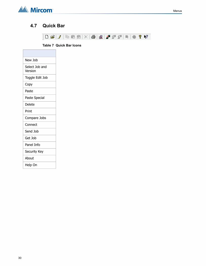
4.7 Quick Bar
Table 7 Quick Bar Icons
New Job
Select Job and Version
Toggle Edit Job
Copy
Paste
Paste Special
Delete
Compare Jobs
Connect
Send Job
Get Job
Panel Info
Security Key
About
Help On
30

5.0 Job Tree and Details PaneThe Job Tree lists the following:
• Job Details
• Base I/O and associated Loops
• Bypass Groups
• Hazard Zones
• Main Display and associated Display Adders
• Dialer
• Common System Status
• Input Summary
• Output Summary
Depending on what is selected in the Job Tree, the Details Pane will dynamically display relevant information.
5.1 Job Details
Figure 26 Job Details
5.1.1 Job Info
Shows details of the job's name, number, creation date and author. The multi-line comments field can be edited and become part of the job's version history.
5.1.2 Language
Specifies the language used to display system messages on the front LCD display and on any LCD annunciator. User defined tags and messages will not be affected.
31

Job Tree and Details Pane
5.1.3 Options
Manual Signal Silence Check to enable the panel's Signal Silence switch.
Fire Drill Check to enable the panel's Fire Drill switch.
Waterflow Retard Operation if disabled, all the initiating circuits configured as waterflow act as non-verified alarms. If enabled, retard operation is performed for initiating circuits configured as waterflow
Auxiliary Disconnect Alarm and Supervision
if enabled the auxiliary disconnect operation, disconnects alarm and supervisory relays disabled the auxiliary disconnect operation has no effect on the alarm and supervisory relays.
Alarm Transmit Silence this feature, if checked, causes the Alarm Transmit and Auxiliary Alarm Relay to reset on Signal Silence rather than by the Reset switch.
Common Supervisory Relay this feature, if checked, makes the common supervisory relay act as a common alarm relay
Signal Isolator Used check this box if isolators are present on the loop 0 powered output circuits.
Two Stage Operation check this box to configure the system as two stage, else it is single stage.
Second Stage Alarm Relay Operation
If enabled, the common alarm relay will be used for second stage only of a two stage system. If disabled, it will be used for both stages.
Positive Alarm Sequence check this box to enable the Positive Alarm Sequence feature. It only applies to alarm input devices with the PA flag (F2) set. This feature cannot be enabled if Two Stage Operation is enabled.
Monitor Alert check this box to have the panel produce alert sounds on monitor in/out activation.
Polled Device Flashes check this box to cause device LEDs to flash when polled.
Class-A Loop check this box if the addressable loop on the base panel operates in Class A mode.
Class-A CLIP Inputs check this box to enable Class A mode for all CLIP input modules.
Strobes Type Specify the Strobe Type that will be used on the panel.
• Gentex
• System Sensor
• Mircom
• Wheelock
Evacuation Code Specify the Evacuation Code that will be used on the panel.
• Continuous
• March Time
• Temporal
• California
Agency Selection Specify the Agency Standard that will be used on the panel.
• ULI Standard
• ULC Standard
32

Job Tree and Details Pane
5.1.4 Timers
5.1.5 Date and Time
5.1.6 Holidays
This dialog allows you to add and remove holiday definitions for use when a panel is configured by checking the Enable Auto After Hours option.
Figure 27 Holidays Window
Table 8 Timers
Timer Type Possible Settings
Signal Silence Inhibit Disabled, 10, 20, 30 seconds, 1 minute
Auto Signal Silence 5, 10, 15, 20, 25, 30 minutes
General Alarm Disabled, 5, 10, 15, 20, 25, 30 minutes
Power Fail Delay 0, 1, 2, 3 hours
Enable Daylight Savings Enable Daylight Savings.
Clock Daily Compensation Specify the number of seconds (signed) to be applied daily to the panel clock.
Enable Auto After Hours Check this to enable after hours. Use the following controls to configure after hours settings
Holidays - Modify Compose a new holiday definition in the YYYY MM DD edit boxes and press Add holiday. You can specify recurring holiday by using wild cards. For further instructions on adding/deleting holidays see Chapter 5.1.6 Holidays.
Daytime Start and End Hours
Specify when daytime begins and ends.
Weekend Start and End Hours
Specify when the weekend begins and ends.
33

Job Tree and Details Pane
To add a new holiday
1. Compose a new holiday definition in the YYYY MM DD edit boxes.
2. If the holiday lasts longer then one day change the value in the Duration edit box to the desired length.
3. Click Add Holiday and the holiday will be added to the Holidays defined list.
To specify recurring holidays
Recurring holidays can be specified by using wild cards.
For a holiday that happens once a year enter 9999 in the YYYY edit box.
• e.g. 9999 01 01 for New Years Day.
Enter 99 for a month or day to specify a recurring holiday.
• e.g. 9999 99 01 to specify that the first of every month is a holiday.
• e.g. 9999 07 99 to specify that the plant is shut down for the whole of July for summer vacations.
As holidays are added or removed, the list on the "parent" form is maintained to be in agreement. An error message is displayed if the limit for the total number of holidays would be exceeded.
To remove a holiday
1. Select the desired date from the Holidays defined list and press Delete Selected Holiday and the holiday will be removed.
2. Press Close to return to the Job Details form.
5.1.7 Port Settings
5.2 Base I/O
Used to set the starting address for AP Devices. If the address is set to 1 CLIP devices are not permitted to be used.
Note: The program prevents you from entering duplicate holidays, but does not check for "nested" holidays.
Port Protocol Printer, None
Port Baud Rate to be added
Note: When mixing modes every address assigned to CLIP removes the equal amount of addresses from the Advanced Protocol addressable sensor and addressable module range.
i
i
34

Job Tree and Details Pane
Figure 28 Base I/O Details
5.3 Loops
The list view displays the hard wired (Conventional) circuits or addressable devices of a Loop, when that loop is selected in the tree. The base set of columns is the same for both, but there are some Product and Loop Type dependencies.
Some columns containing advanced or internal information are normally hidden. They are listed as Visible / No in the following table. Other columns are conditionally visible. There are up to three Flag columns (F1, F2 and F3) for flags of various types.
Table 9 Loop Details
Name Visible Description
Addr Yes For regular addressable devices, the displayed address is the same as device address. For conventional circuits display adder & circuit on adder.
Lp No Loop Number
Ckt No No An internal, sequentially assigned number. One set for inputs, another for outputs.
Device Yes Conventional - fixed hardware loop circuits. Addressable - chosen when Adding Device(s). Can be edited conditionally.
Type Yes The process Type of the Device. Can be edited (combo box). The list of Types shown in the combo box will depend on the Device. E.g. relay modules can be assigned Relay, Signal or Strobe
Sens On Addressable Loops
The sensitivity of various sensors. Displays a combo with %age equivalents of internal absolute values. Takes into account jurisdiction (ULI vs. ULC).
Sens B On Addressable Loops
The after hours and night time sensitivity of a system configured to have the after hours option.
Tag1 Yes The text of the tag, in two 20 character fields, representing the lines displayed on the front panel when an alarm occurs, etc.
35

Job Tree and Details Pane
5.4 Bypass Groups
The list view displays the list of bypass groups currently defined in the system. You can correlate any input or output device to a group, as well as a Led to indicate its status by selecting Insert / Add Correlations from the main menu. The Led to be correlated must be defined as "Bypass Zone" type on one of the RAX 1048TZDS display adders. Once a Led is correlated to a bypass group, it will be used exclusively to indicate the status of that group and it can not be used for other purposes.
Some columns containing advanced or internal information are normally hidden. They are listed as Visible / No in the following table.
5.5 Hazard Zones
The Hazard Zone area displays any configured Hazard zones with the following information.
Table 10 Flag Columns - F1, F2, F3
Name Description
NS Non Silenceable - used on inputs and supervised Outputs.
NF Keeps the device LED off when device is active.
NB Non Bypassable used on relays.
GA 2nd Stage Alarm - used in a two stage system .
RR Rate of rise. For heat/thermal detectors only. It indicates that alarm activation of this device is based on the Rate of Rise algorithm.
CA Class A wiring. For mini-switch, switch or sounder modules only. It indicates that the wiring of this device is Class-A.
Table 11 Bypass Groups
Name Visible Description
No. Yes Group number of the bypass group
Tag Yes Label of the bypass group
No. Number of the Hazard Zone.
Zone Label Label of the Hazard Zone.
Type Configured as Pre-Action/Agent or Deluge.
Counting Zone Type
Configured as Single, Double, Triple, 2 Input Type.
Abort Type Configured as ULI, IRI, NYC, AHJ.
Rel Delay The maximum value for the RDT is 60 seconds.
Soak Delay The maximum value for the SDT is 600 seconds.
Man Rel Delay The maximum value for the MRDT is 60 seconds.
Man Rel Priority
To ensure a Manual Release Switch overrides an Abort Switch, in the FX-3500 configuration software set the Man Rel Priority flag for the Hazard Zone zone to Yes.
36

Job Tree and Details Pane
5.6 Main Display
This form view appears in the top, right pane when the Main Display item is selected in the Job Tree view.
5.7 Display Adder
This list view appears in the top, right pane of the user interface when a display adder is selected in the Job Tree. The list displays items (LEDs and Switches) of all the frames on the selected Display Adder.
User Message. System Normal - specify the message to display on the front panel LCD when the system is currently normal (no alarm or trouble).
Passcodes Level 1 - Not required
Level 2 and 3 - Specify the passcode for each level of access. Passcodes must be numeric and a maximum of 20 digits long.
Access Levels.
Specify the level of access for various front panel actions. Level 1 does not require a passcode but a key to the panel is required Level 2 is similar to Level 1 with additional access to disable zone function, fire alarm devices, sensitivity, time and date settingsLevel 3 has access to all functions
Table 12 Display Adder Info
Name Visible Description
Idx Yes Index - the zero based position of the item on the adder.
CPU No The CPU Number of the Annunciator to which the adder is attached.
Unnamed Yes
Linked Item - contains an asterisk if the item shares the same LedGrp with other items. This means that correlations to one such item are added to all linked items. Linked Items can be created when Paste Special is used. The linked items can be viewed with the Linked Items dialog.
Frame No The Frame Number. An adder may contribute several frames to an annunciator. The frame numbers are zero based.
LED No
The number (zero based) of the first LED of a logical group. For example, an HOA adder has three LEDs per slide switch. This column would show 0 for Idx 0, 3 for Idx 1, etc. Due to the way some adders are arranged (hardware) the LED numbers are in irregular sequences.
Sw No The Switch number (if any) associated with the Idx.
Type Yes Initially this is the Type of display item. The values in the combo box depend on the Adder/Frame type.
Assignment Yes Dependent on the Type.
F1 Yes If the item is some form of switch (Bypass, Slide Switch) etc., then this flag column can be set to ER (enable required) or none.
37

Job Tree and Details Pane
5.8 Dialer
This form is displayed when the Dialer tree item is selected. It allows you to configure the UDACT / Dialer. The dialer can dial out on two phone lines. You must configure an account and specify the line attributes for both. Line 2 can dial a cell phone. If this is the case the auto test can be reduced from daily to monthly. The panel can also be configured from the configuration tool by dialing in to the dialer. See Connect for full details.
5.8.1 Account 1
5.8.2 Account 2
5.8.3 Line 1
F2 Yes For Bypass and Manual Switches, this flag can be set to AR (Aux Reset Required). For Correlatable Switches it can contain NS (Non silenceable)
F3 Yes For Correlatable Switches this flag can contain GA (2nd stage, GA device). For Bypass and Manual Push Switches it can contain SR (System Reset Required)
F4 Yes
This flag prevents addressable device’s LED from flashing (and activating the sounder when present). The LED flashes by default and may only be changed to NO FLASH if the Authority Having Jurisdiction allows.
Tag 1 Yes
Except for Common Controls, System Status and Man Ena, a 20 character tag can be entered. It will be used to identify the control in messages, etc. For some Type/Assignment combinations the tag is generated and cannot be edited.
Tag 2 Conditional Correlatable Switches (being analogous to Input Zones) accept a second line of 20 characters.
Account ID Six digit decimal for the SIA report formats and four digit hexadecimal for Contact ID.
Telephone Text Field for telephone number.
Report Format Choose from SIA110, SIA300, Contact ID
Account ID Six digit decimal for the SIA report formats and four digit hexadecimal for Contact ID.
Telephone Text Field for telephone number
Report Format Choose from SIA110, SIA300, Contact ID
Dial Using Tone/Pulse
Wait Check to wait for dial tone before dialling
Table 12 Display Adder Info (Continued)
Name Visible Description
38

Job Tree and Details Pane
5.8.4 Line 2
5.8.5 Report Priority
5.8.6 Timers
Dial Using Tone/Pulse
Wait Check to wait for dial tone before dialling
Alarm Choose one of the two accounts to use to report Alarms
Supv Choose one of the two accounts to use to report Supervisory alerts
Trouble Choose one of the two accounts to use to report Troubles
AC loss delay 0-20 hours. Use this menu to delay the reporting of AC loss trouble on the dialer for the programmed time period.
Line 2 cellular test
Use this menu to set the test report date for the cell phone setup. Uncheck this box if there is no test reporting for a cell phone, or if the phone line is a regular line. Set Day of month from 1 to 28 to schedule a test for Line 2 on a certain day of the month. See section 5.8.7 for more information.
When a cell phone service is employed for the panel, it should only be connected to telephone line #2 CO interface. Also, the dial tone detection feature of Line 2 should be disabled for cell phone application.
Auto test at Use this function to set the time for the automatic test. When this test is performed, the test report is sent to the monitoring station. This test must be performed at least once a day.
The Auto test time can be configured to:
12:00 a.m. to 5:59 a.m.: test every 24 hours
6:00 a.m. to 11:59 a.m.: test every 6 hours
12:00 p.m. to 23:59 p.m.: test every 12 hours
If the Line 2 cellular test is disabled, then the test alternates between Line 1 and Line 2. See section 5.8.7 for more information.
39
Job Tree and Details Pane
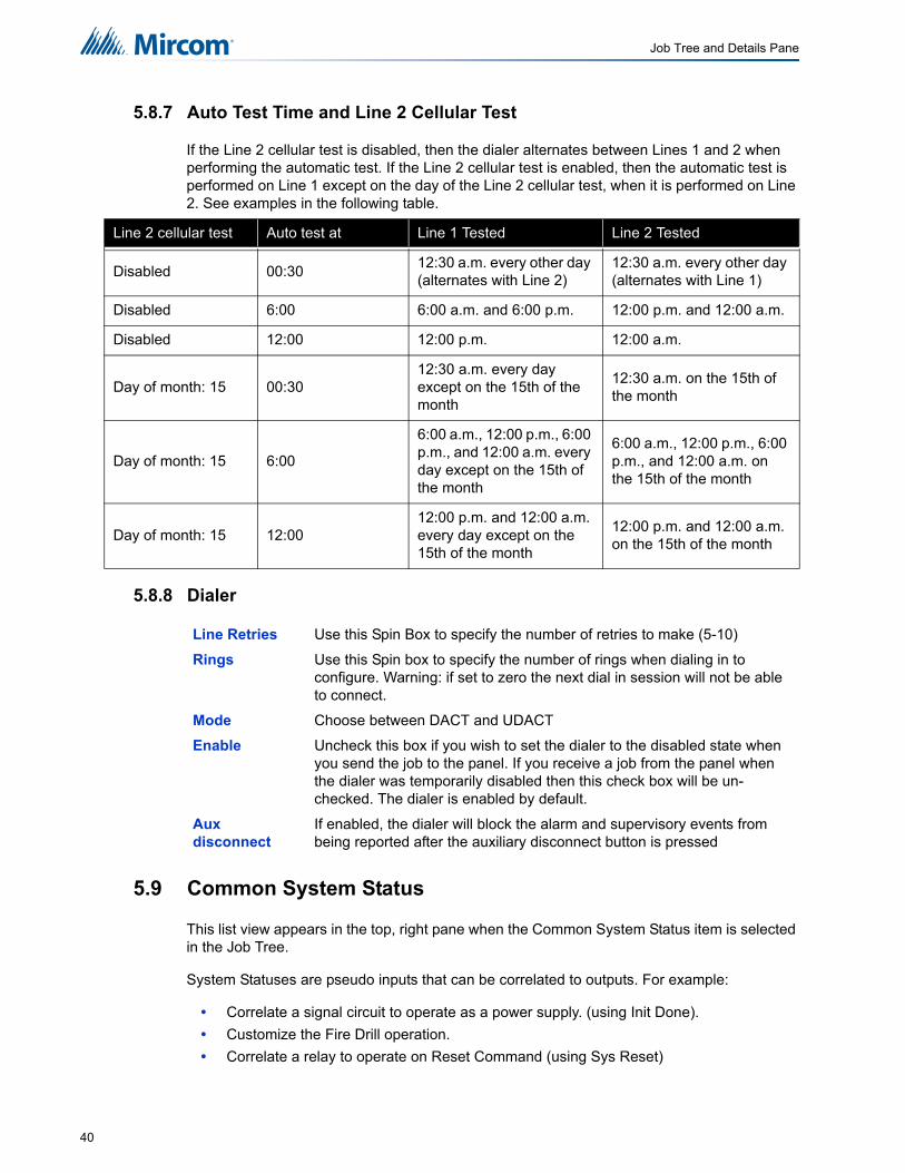
5.8.7 Auto Test Time and Line 2 Cellular Test
If the Line 2 cellular test is disabled, then the dialer alternates between Lines 1 and 2 when performing the automatic test. If the Line 2 cellular test is enabled, then the automatic test is performed on Line 1 except on the day of the Line 2 cellular test, when it is performed on Line 2. See examples in the following table.
5.8.8 Dialer
5.9 Common System Status
This list view appears in the top, right pane when the Common System Status item is selected in the Job Tree.
System Statuses are pseudo inputs that can be correlated to outputs. For example:
• Correlate a signal circuit to operate as a power supply. (using Init Done).
• Customize the Fire Drill operation.
• Correlate a relay to operate on Reset Command (using Sys Reset)
Line 2 cellular test Auto test at Line 1 Tested Line 2 Tested
Disabled 00:3012:30 a.m. every other day (alternates with Line 2)
12:30 a.m. every other day (alternates with Line 1)
Disabled 6:00 6:00 a.m. and 6:00 p.m. 12:00 p.m. and 12:00 a.m.
Disabled 12:00 12:00 p.m. 12:00 a.m.
Day of month: 15 00:3012:30 a.m. every day except on the 15th of the month
12:30 a.m. on the 15th of the month
Day of month: 15 6:00
6:00 a.m., 12:00 p.m., 6:00 p.m., and 12:00 a.m. every day except on the 15th of the month
6:00 a.m., 12:00 p.m., 6:00 p.m., and 12:00 a.m. on the 15th of the month
Day of month: 15 12:0012:00 p.m. and 12:00 a.m. every day except on the 15th of the month
12:00 p.m. and 12:00 a.m. on the 15th of the month
Line Retries Use this Spin Box to specify the number of retries to make (5-10)
Rings Use this Spin box to specify the number of rings when dialing in to configure. Warning: if set to zero the next dial in session will not be able to connect.
Mode Choose between DACT and UDACT
Enable Uncheck this box if you wish to set the dialer to the disabled state when you send the job to the panel. If you receive a job from the panel when the dialer was temporarily disabled then this check box will be un-checked. The dialer is enabled by default.
Aux disconnect
If enabled, the dialer will block the alarm and supervisory events from being reported after the auxiliary disconnect button is pressed
40

Job Tree and Details Pane
5.10 Input / Output Circuit Summary
The Job Tree always contains an Input Summary and Output Summary item. Select either of these items to see a list of all of the circuits on the job.
This view of the Input Summary gives an Input UDACT reference number and tag required for programming by the Central Monitoring Station. On products that support them, this list may include Correlatable Switches. These will not have a value in the Loop and Address columns.
This view of Output Summary gives an output UDACT reference number and tag required for programming by the Central Monitoring Station.
41

6.0 Adding Items to the Job6.1 Add Loop Controllers
To add an ALC-636 Dual Loop Adder
1. Right click anywhere in the Job Tree.
2. Click Add Loop Controller.
3. Loop 2 and Loop 3 will now appear in the Job Tree under Base I/O.
6.2 Add Annunciator
To add an Annunciator
1. Right click anywhere in the Job Tree.
2. Click Add Annunciators.
3. In the Add Annunciator window enter the following information:
4. The dialog remains open for adding more Annunciators. Press Close to dismiss the dialog.
6.3 Add Correlations
Figure 29 Add Correlations Window
Select Type This control lists the types of Annunciator that can be added to the job.
The list will only shows the types that are allowed for your product type.
Number to add
Edit this number to add more than one Annunciator to the job.
Tag This field is enabled only if the panel product supports this feature. Ifenabled, enter a description for the Annunciator. If more than oneAnnunciator is added they will all receive the same tag. Tags can beedited in the Annunciator Information view.
Add Press Add to add Annunciator(s) of the selected type. The Job Tree willbe updated to show the new Annunciator. If the limit for the job isexceeded an error message will be displayed.
42

Adding Items to the Job
The Add Correlations window shows a tab for every category of circuit or display item, etc. that can be correlated to the items selected in the Details Pane of the GUI. The tab categories mirrors and synchronizes with those of the Correlations View. When a tab is selected on one the corresponding tab is activated on the other.
The content of each tab is dynamically updated as correlations are added or deleted so that the window always shows the items that are available.
To Add Correlations
1. From the Details Pane right click an item and select Add Correlations. The Add Correlations window appears.
2. Select the items to be correlated (hold down the Ctrl key and right click the mouse to select multiple rows) and click the Add button.
3. The window remains open and more correlations can be made, selecting items from other tabs if necessary. The dialog remains open when another target is selected in Configurator's Details Pane.
4. Click the Close button to close the window.
6.4 Add Device
Figure 30 Add Devices window
To add Devices
1. In the Job Tree select Loop1, Loop2 or Loop3.
2. From the Details Pane right click an item and select Add Devices. The Add Devices window appears.
43

Adding Items to the Job
3. Enter the following information:
4. Click Yes to continue
5. The Configurator will add the remaining devices where ever empty addresses exist. The warning message will not appear again for this transaction.
6. Click No to stop.
7. The block of sequential devices added so far will be committed. No further devices will be added. A second message will tell you how many devices were successfully added.
8. Cancel to abort.
9. The entire transaction will be rolled back. No devices will have been added.
10. If at any time during the transaction there are no more available addresses, the entire transaction is rolled back. No devices will have been added.
11. After the operation is complete the dialog remains open for re-use. The Address value is adjusted to account for the devices just added.
12. If there are no available addresses for the chosen Type then the Add button is disabled. You can select another type, or close the dialog.
13. The Close button dismisses the dialog.
6.5 Add Display Adder
Figure 31 Add Display Adder window
Type major device type, with choices such as Photo Det, Ion Det, Supv Opt Mod, etc.
Process As combo box is adjusted according to the device type.
Address specify the address for the new device. This defaults to the lowest available address for the chosen type. It takes into consideration that some types (Dual Acclimate and Fire Phone) require two addresses, one at the chosen address and one at the address + 100. An address appears in the list only if its paired address is also free.
Number to Add Specifies how many devices to add by changing the Number to add value. The Configurator will attempt to allocate the devices sequentially, starting with the address you selected. If there are insufficient sequential addresses you will be shown a message with three options.
44

Adding Items to the Job
To add a Display Adder
1. In the Job Tree select one of the listed annunciators and right click an item and select Add Display Adder. The Add Display Adder window appears.
2. From the drop down menu select the desired Display Adder.
3. Click Add and the Display Adder will be added to the Job Details under the selected Annunciator.
6.6 Deleting Correlations
If you change a Device Type, you might see the following message. This can happen after you have performed an Auto Configuration on the panel.
Figure 32 Change process type warning
If you want to change the Device Type of a circuit that is correlated with a hazard zone, youmust delete the hazard zone from the correlations first.
To delete a correlation
1. Click the correlation, and then click the Edit menu and click Delete Item.
2. Click Yes to delete the correlation.
Hold down the Shift key to select more than one correlation at once.
6.7 Hazard Zones
Hazard zones can be added to FX-3500RCU panels. To determine if you have an FX-3500RCU, go up to your panel, press Manual (M), and then press Information (?). If the letters RCU are displayed at the end of the first line, your panel is an FX-3500RCU.
Hazard zones are configurable by correlating input devices, releasing circuits, (pre)release signals, and manual release and abort switches. For more information on Releasing Operation, see LT-1091 FX-3500RCU Releasing Application Guide on http://www.mircom.com.
Note: If you send a job with hazard zones to an FX-3500, the FX-3500 configuration software will display an error message telling you that the panel is the wrong model and that the job can only be sent to an FX-3500RCU panel.
Notes: Abort switches are only configurable in Preaction/Agent release applications.
Soak Delay timer is only configurable for Deluge applications.
i
i
45
Adding Items to the Job
6.7.1 Counting Zone Type
Releasing applications must be configured with one of the following Counting Zone types:
6.7.2 Abort Type
Releasing applications must be configured with one of the following Delay Timer types:
6.7.3 Configurable Timers
Releasing applications may be configured with the following timers:
Single Activation of any one input device correlated to the hazard zone will initiate the release process.
Double Activation of any two input devices correlated to the hazard zone will confirm the alarm and initiate the release process.
Triple Activation of any three input devices correlated to the hazard zone will initiate the release process.
2 Input Types Activation of any two different input device types (ion, photo, heat etc.) correlated to the hazard zone will initiate the release process.
ULI Press Abort and the timer continues to count down and stops and holds at 10 seconds. Release the ABORT switch and the timer resumes the countdown at 10 seconds.
IRI Same as ULI with the following condition: For the Abort switch to function, you must press and hold the Abort switch before the second zone goes into alarm.
NYC Pressing the Abort switch causes the control panel to add 90 seconds to the Release Delay Timer (RDT).
Pressing and holding the Abort switch stops the Release Delay Timer (RDT) from counting down. Releasing the Abort switch resumes the count down of the RDT.
AHJ The timer does not start while you press and hold the Abort switch. Press the Abort switch and the timer resumes counting down. Press the Abort switch again to restore the timer to its full value. Release the Abort switch and the timer resumes counting down.
Release Delay Timer(RDT)
The amount of time from when the Hazard Zone is activated via correlated input devices until release.
The maximum value for the RDT is 60 seconds.
Soak Delay Timer(SDT)
The amount of time that the releasing circuit will be active. Upon the expiration of Soak Timer, the releasing circuits will be shut off. Only configurable in Deluge applications.
The maximum value for the SDT is 600 seconds.
Configuring the SDT to 0 seconds causes the releasingcircuits to shut off ONLY when the system is reset.
Manual Release Delay Timer(MRDT)
The amount of time from when the Manual Release Switch is pressed until release.
The maximum value for the MRDT is 60 seconds.
46
Adding Items to the Job
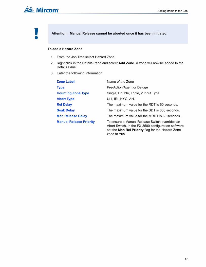
To add a Hazard Zone
1. From the Job Tree select Hazard Zone.
2. Right click in the Details Pane and select Add Zone. A zone will now be added to the Details Pane.
3. Enter the following Information
Attention: Manual Release cannot be aborted once it has been initiated.
Zone Label Name of the Zone
Type Pre-Action/Agent or Deluge
Counting Zone Type Single, Double, Triple, 2 Input Type
Abort Type ULI, IRI, NYC, AHJ
Rel Delay The maximum value for the RDT is 60 seconds.
Soak Delay The maximum value for the SDT is 600 seconds.
Man Release Delay The maximum value for the MRDT is 60 seconds.
Manual Release Priority To ensure a Manual Release Switch overrides an Abort Switch, in the FX-3500 configuration software set the Man Rel Priority flag for the Hazard Zone zone to Yes.
!
47

7.0 Managing the DatabaseThe database stores all jobs and their information. Databases can be Backed Up, Restored or Compacted.
7.1 Backup Database
Backup database makes a copy of the Master Database.
Figure 33 Backup Database
To Backup the Database
1. Click File > Backup Database. The file location specified in the User Preference appears and the file name will be in the form of YYYY-MM-DD.mdb.
2. Click Save. A popup window appears notifying you of a successful backup.
The backup can be used by the Restore Database command to recover all of the jobs in the database. You can also use the Import command to recover selected jobs from a backup. Backup your Master Database often and store a copy of the resulting file on a CD or other media.
7.2 Restore Database
Restore database reads a database file and imports every job found there, after first deleting all of the jobs in the current database. The backup database could have been produced by an older version of the configuration tool, in which case all necessary conversion is performed.
Note: If the Keep Only Latest Versions After Backup option of User Preferences is enabled, old versions of each job in your main database will be deleted, retaining only the latest version of each job.i
48
Managing the Database
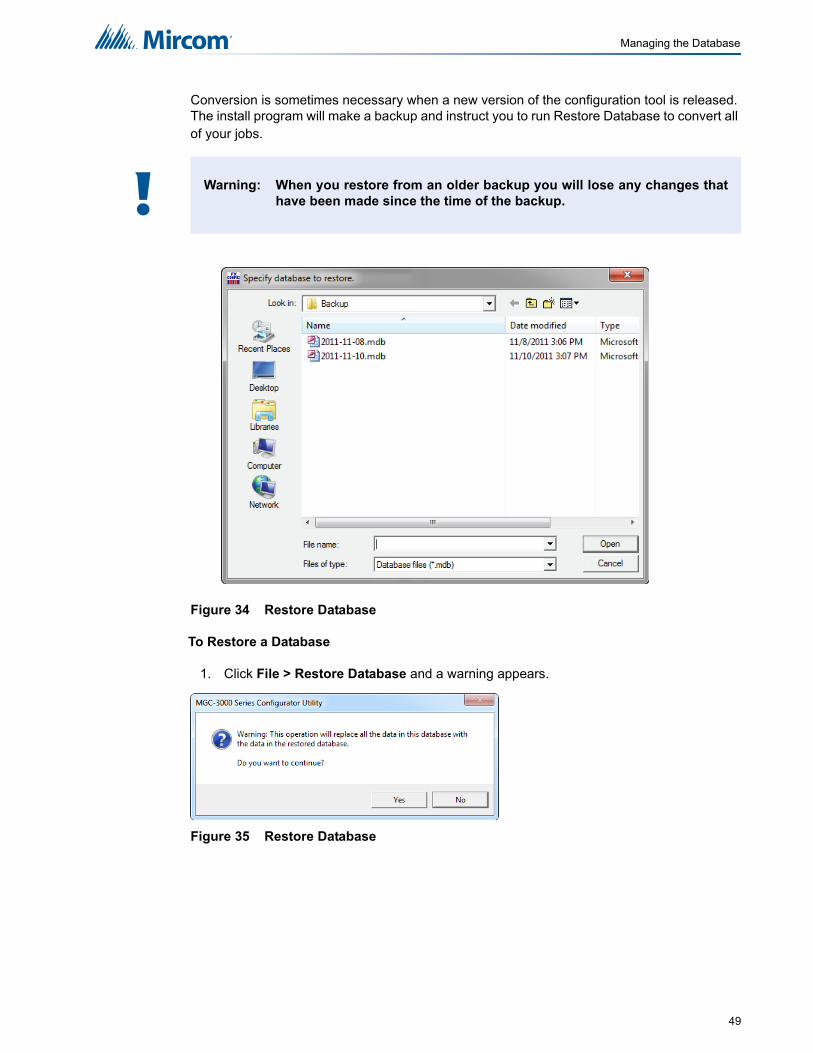
Conversion is sometimes necessary when a new version of the configuration tool is released. The install program will make a backup and instruct you to run Restore Database to convert all of your jobs.
Figure 34 Restore Database
To Restore a Database
1. Click File > Restore Database and a warning appears.
Figure 35 Restore Database
Warning: When you restore from an older backup you will lose any changes thathave been made since the time of the backup.!
49

Managing the Database
2. Click Yes to continue.
3. The file location specified in the User Preference appears and the file name will be in the form of YYYY-MM-DD.mdb.
4. Select the desired database and click Open. A popup window appears notifying you of a successful restoral.
7.3 Compact Database
A database that has been the subject of many deletions and additions can become fragmented and occupy more space than required. Compact Database executes a standard MS-Access utility to recover the space and improve performance.
To Compact a Database
1. Click File > Compact Database. A status window will appear. There will be no further notification.
Note: This may take several minutes for a large database.i
50
8.0 Managing Jobs8.1 Create a New Job
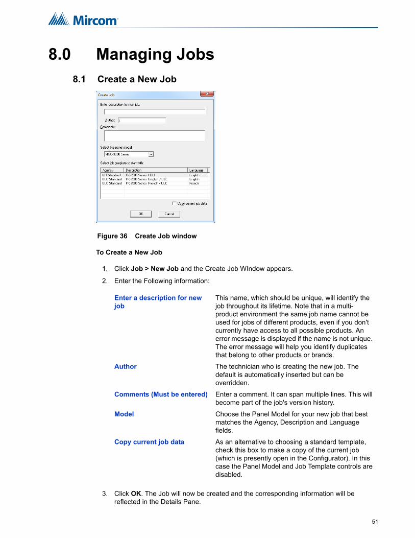
Figure 36 Create Job window
To Create a New Job
1. Click Job > New Job and the Create Job WIndow appears.
2. Enter the Following information:
3. Click OK. The Job will now be created and the corresponding information will be reflected in the Details Pane.
Enter a description for new job
This name, which should be unique, will identify the job throughout its lifetime. Note that in a multi-product environment the same job name cannot be used for jobs of different products, even if you don't currently have access to all possible products. An error message is displayed if the name is not unique. The error message will help you identify duplicates that belong to other products or brands.
Author The technician who is creating the new job. The default is automatically inserted but can be overridden.
Comments (Must be entered) Enter a comment. It can span multiple lines. This will become part of the job's version history.
Model Choose the Panel Model for your new job that best matches the Agency, Description and Language fields.
Copy current job data As an alternative to choosing a standard template, check this box to make a copy of the current job (which is presently open in the Configurator). In this case the Panel Model and Job Template controls are disabled.
51

Managing Jobs
8.2 Open Job
Figure 37 Select Job and Version window
Open Job allows the user to select a job and job-version in the database and open it in the user interface. The Select Job list view shows all of the jobs on the database. By clicking on the column heading you can sort the jobs by
• Job Number
• Job Description
• Product (where more than one product is supported)
The Select Version list view shows all of the versions of the selected job. This includes the date and a description.
To open a Job
1. Click Job > Open Job and the Select Job and Version window appears.
2. Select the desired Job and click OK. The Job will now be opened.
8.3 Import Job
Figure 38 Import Job window
This command imports a selected job/version from an external database or serialized job archive as created by the export or Backup Database commands. and converts the job to the
52
Managing Jobs
current version if necessary. The user chooses the type (MDB or Serialized Archive) and location of the file to read. The location defaults to the Job File folder specified in User Preferences.
If the selected type is MDB, then the Microsoft Access database (usually a database that resulted from a Backup Database) is opened. A list view, similar to the Open Job dialog, displays jobs contained in the database. The list will be restricted to the Products for which the user is authorized.
The chosen job is read and copied to the current database using logic common to Restore Database. If the version of the source database is not too old (no forward conversion is possible) and is not younger than the current database, then any necessary conversion is performed. If the database version is not compatible, an error is displayed.
If the selected type is fx2job (a serialized archive, usually the result of Export) then the Jobs found in the archive's index are listed. The data structures are de-serialized and treated very much as if they had been downloaded from a panel. The program adjusts older versions of data structures to the current standard, extracts the data and stores the job on the database.
If the same job (identified by its name) is already on the database, then the next highest version is assigned to the job.
If a job with the same name is not on the database, then a new job is created.
To import a job
1. Click Job > Import Job and the Select file to import window appears.
2. Select the desired Job and click OK. The Job will now be opened.
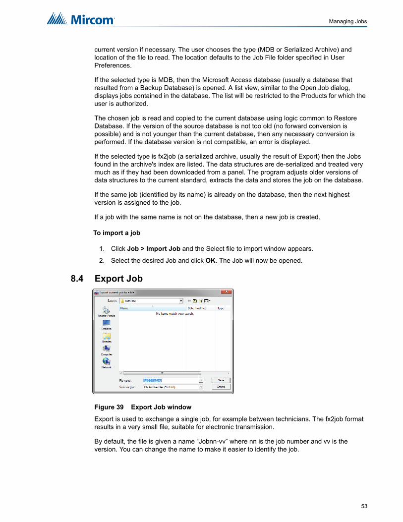
8.4 Export Job
Figure 39 Export Job window
Export is used to exchange a single job, for example between technicians. The fx2job format results in a very small file, suitable for electronic transmission.
By default, the file is given a name “Jobnn-vv” where nn is the job number and vv is the version. You can change the name to make it easier to identify the job.
53

Managing Jobs
To Export a job
1. Click Job > Export Job and the Export Job window appears.
2. Select the file type to export:
3. Click Save and the job will be exported.
8.5 New Version
To create a new Job version
1. Click Job > New Version. The New Job Version window appears.
2. Enter who is making the change, any related comments and click OK. The version will now be saved.
8.6 Delete Job Version
Deleting the Job Version deletes the currently open Job from the Database. It will no longer be accessible form the Version History window.
To Delete the currently open Job version
1. Click Job > Delete Version. A window asking if you want to permanent delete the current version appears.
2. Click OK. The job version is now deleted.
8.7 Version History
Figure 40 Version History window
.mdb A Microsoft Access database containing a single job is produced.
.fx2Job A compact archive file is produced.
54

Managing Jobs
The version history of the current job is displayed in list form, beginning with the most recent version.
To open the Version History Window
1. Click Job > Version History. The version history window appears.
2. Click OK to close the window and return to the main GUI.
8.8 Compare Job Versions
For an in depth explanation on Comparing Jobs and Differences mode see see Chapter 12.0 Differences Mode / Differences Report.
Figure 41 Select Job to Compare window
Number The version number. Each time a new version is created, either with the New Version command or by getting a job from the panel or an archive, a new version number is allocated.
Date The date and time the version was created.
Changed by The user who created the version.
Description The description, as entered when the new job version was created.
Type Uploaded- the new job version was a result of a Get Job. New Job - the user created a new version manually
Status Either Locked- the job has been sent to the panel and is locked against editing or Editable.
55

Managing Jobs
To Compare Jobs
1. Click Job > Compare Jobs. The Job to Compare window appears.
2. Select the Secondary Job, Version, if you would like to show identical Items and any Advanced Options. For more information see Chapter 8.8.1 Advanced Compare Options.
3. Click OK and you will Enter Differences Mode.
Primary Job This field reminds you which job you have already established as primary job: the base job against which the secondary job will be compared.
Select Secondary Job: Select Version
Use the combination of Job and Version to select the secondary job. The job defaults to the same one you established as Primary. Normally you will only need to choose a newer version of the same job. You are prevented from choosing the same Job and Version for Primary and Secondary.
Just as when establishing the primary job, you can sort the list of secondary jobs by Job Number, Description or Product
Show Identical Items Check this box if you want to see not only changes, but also those items that stayed the same. Normally you will leave this un-checked. Differences are easier to see and Print generates less output if identical items are not included.
Advanced Options When you press this button the Advanced Options dialog is launched. Here you can change some of the more advanced filtering options. They are normally all checked by default and in most situations do not need to be changed.
See How to Compare Job Versions for full details
56

Managing Jobs
8.8.1 Advanced Compare Options
Figure 42 Advanced Compare Options window
Modified Check this box to include any item that has been modified. (Modified means that it is the same adder, circuit, switch, etc. but some attribute has been changed.) This box is checked by default. You would only un-check this box if you did not want to see items that have been modified.
Present only in Secondary Job
Check this box to include items that are only present in the secondary job. This means that Loop Adders, Annunciators, Display Adders, circuits, etc. that were not on the base job will be included. This box is checked by default. You would only un-check this box if you did not want to have new additions reported.
Present only in Primary Job
Check this box to include items that were only present in the primary job. This means that Loop Adders, Annunciators, Display Adders, circuits, etc. that were removed from the primary job will be included. This box is checked by default. You would only un-check this box if you did not want to have deletions reported.
Advanced Options
When you press this button the Advanced Options dialog is launched. Here you can change some of the more advanced filtering options. They are normally all checked by default and in most situations do not need to be changed.
Notes: Filtering of 'Present only in Secondary' and 'Present only in Primary' do not apply when presenting the tree. The tree is shown in its entirety, regardless of these settings. The filtering is only applied to the Device, Display Item and similar lists. It is intended to make it easy to see what components have been physically added or removed from the job.
Correlations are not considered to be items in this context. If a correlation was added, then that is effectively a modification to the item that received the correlation.
If you chose to check Present only in Secondary Job and/or Present only in Primary Job, but you do not check Modified, then the circuits, etc. that have only had correlation changes will not be included.
i
57
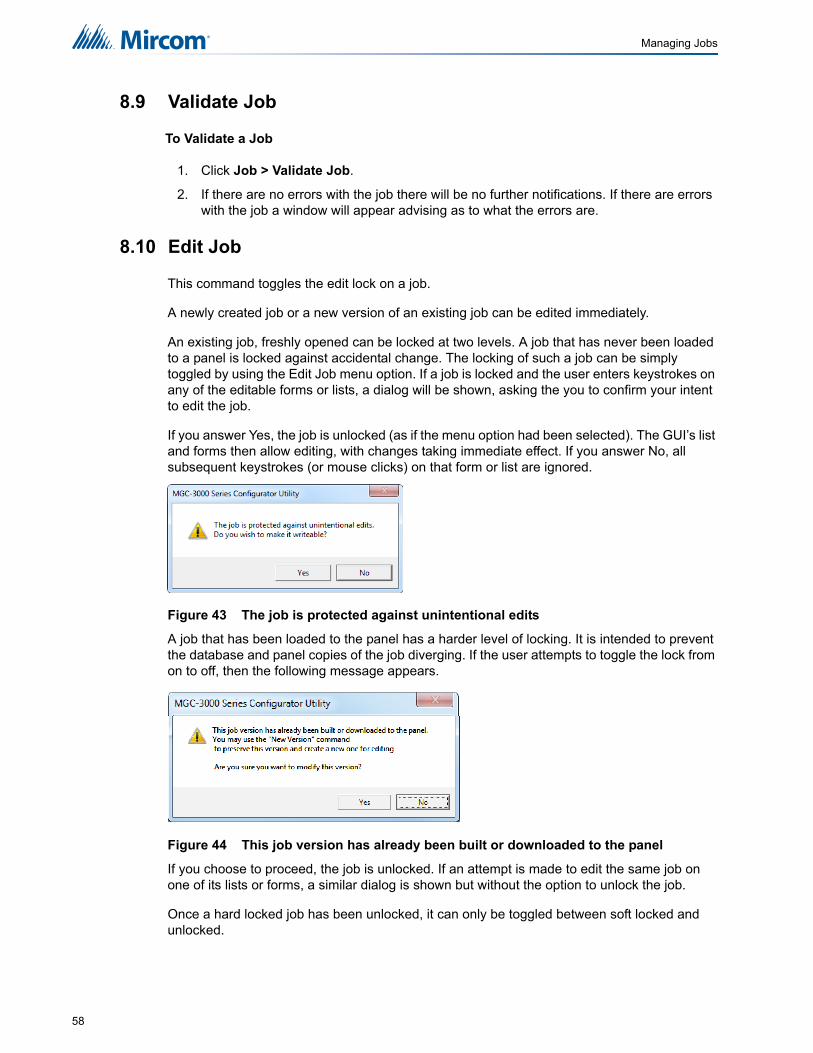
Managing Jobs
8.9 Validate Job
To Validate a Job
1. Click Job > Validate Job.
2. If there are no errors with the job there will be no further notifications. If there are errors with the job a window will appear advising as to what the errors are.
8.10 Edit Job
This command toggles the edit lock on a job.
A newly created job or a new version of an existing job can be edited immediately.
An existing job, freshly opened can be locked at two levels. A job that has never been loaded to a panel is locked against accidental change. The locking of such a job can be simply toggled by using the Edit Job menu option. If a job is locked and the user enters keystrokes on any of the editable forms or lists, a dialog will be shown, asking the you to confirm your intent to edit the job.
If you answer Yes, the job is unlocked (as if the menu option had been selected). The GUI’s list and forms then allow editing, with changes taking immediate effect. If you answer No, all subsequent keystrokes (or mouse clicks) on that form or list are ignored.
Figure 43 The job is protected against unintentional edits
A job that has been loaded to the panel has a harder level of locking. It is intended to prevent the database and panel copies of the job diverging. If the user attempts to toggle the lock from on to off, then the following message appears.
Figure 44 This job version has already been built or downloaded to the panel
If you choose to proceed, the job is unlocked. If an attempt is made to edit the same job on one of its lists or forms, a similar dialog is shown but without the option to unlock the job.
Once a hard locked job has been unlocked, it can only be toggled between soft locked and unlocked.
58

9.0 Working with the Panel9.1 Connect
Figure 45 Connection window
To connect to the panel
1. Select a connection type:
2. Click Connect. Once a connection has connected you might see the following window detailing that the panel time and the PC do not match. Click Yes and the update Panel time window appears.
3. Set the time and click OK.
4. You will be informed that the time has been updated. Click OK.
Direct Serial Select this option if you have connected a serial cable directly from the serial port (or USB / UIMIA) of your computer to the fire alarm panel.
Modem Select this option if the fire alarm panel is capable of being programmed remotely. The combo-box will list the modem(s) found on your computer.
Telephone Number Enter the phone number to which the fire alarm panel is connected. The text field will show the last number you entered.
59
Working with the Panel
9.2 Send Job
To send a job to the panel
1. Click Panel > Send Job. A confirmation window will appear.
2. Click Yes. Once the job has been successfully sent a confirmation window will appear. Click OK.
9.3 Get Job
To get a job from the panel
1. Click Panel > Get Job. The create job window will appear.
2. Enter the Job information and click OK. Once the job has been retrieved a confirmation window will appear. Click OK.
9.4 Panel Information
This dialog displays a summary of panel and the Configurator information, with options to view more detail. The information includes:
• The Product Version
• Name and Version of the job currently loaded on the panel.
• Model (deduced from Product, System (build) Type and Hardware Features).
• The Date it was sent
• The ESD and Tech who sent / owns the job. (For products secured with a key)
• Security Key SIN. (For products secured with a key)
• FXConfig Version
• Date and Time Last Changed
• Number of times auto configured.
• The Panel Time.
An Advanced button launches Advanced Panel Info which retrieves and displays the Type, Product Version, Language, on line status, etc. of all Nodes and their CPUS.
An Update button allows the panel time to be corrected/updated from the Configurator for those products that support the feature.
9.4.1 Advanced Panel Information
Polls all the nodes on the panel and checks their status against the configuration. This information may not appear for all annunciators.
The following information is displayed:
• Node - address
• Type - CPU Type
• Version - current firmware version (n/a for RA1000)
• Language - language in firmware (standard messages/menu etc.),
• System Type - one of the following
• Compact Build
60

Working with the Panel
• Large Build
• HW Type - "base" or "Exp. Master" for the Large board
• HW Vers - currently always VX.X.X,
• Status - one of the following
• Online
• Not responding
• Wrong type (configured as "xxxx" )
• Unconfigured CPU
• Firmware version mismatch.
• Address mismatch (configured as node xx).
• Offline trouble: xxx xxx
9.5 Event Log
The Event Log dialog has 2 tabs, one for the General log and one for the Alarm log. The operations of each tab are identical. When the dialog is displayed, events of the currently active tab will be read from the panel automatically in the background and start filling the list with event data.
A simple status field is shown at the bottom to indicate the progress of reading the events. Events are shown on a list with the columns: No., Date and Time and Event Description. Scroll the list up or down to see more events.
You may stop the background read process by clicking the Stop button at any time. To re-read the list, click the Refresh button. The list of the active tab will be cleared and the background read will be initiated again. It is not necessary to press the Refresh button just to read any new events because they will be added to the top of the list automatically if the background read is not stopped.
Clicking the Export button will let you export the list of the active tab to a CSV file. The CSV file could be imported to common spreadsheet software such as MS Excel for further analysis. Click Close to close the dialog.
61

Working with the Panel
9.6 Upgrade Firmware
To Upgrade the firmware
1. Click Panel > Upgrade Firmware and a wizard appears.
2. The following dialogue should appear:
Figure 46 Upgrade Firmware Wizard
3. Browse to the location of the firmware file, press Next and follow the on screen instructions in the subsequent dialogue:
Figure 47 Upgrade Firmware Wizard
4. Press Next and a final dialogue will display showing the firmware upgrade status.
62

10.0 Tools Menu10.1 Extract All DB
This command extracts every job on the database and produces an individual database file for each. It has the same effect as running Export Job for every job. Unlike Export Job, you do not have the choice of making a compact serial archive (FX2Job).
10.2 Validate All
This command will validate the latest version of every job on the database. It also produces a C file for each job and stores it in the Job Build folder.
It has the same effect as using Validate Job on each job. Before the process starts, it displays the Build Job dialog so that you can specify the version of the product to be built.
10.3 Build Job
This command validates and builds the current job, producing a C file in the Job Build folder.
It performs the build assuming the latest product version.
10.4 Build Job Old Versions
This command validates and builds the current job, producing a C file in the Job Build folder.
It first shows the Build dialog so that you can choose the product version. You can use this command to produce the C files for older versions of the panel.
10.5 Link Statistics
This command displays statistics for the connection between the Configurator and the fire alarm panel.
10.6 Log Send
Toggle the current state of the "dump on send" option. Causes the ".c" file to be produced and dumped on a Get Job.
10.7 Log Get
Toggle the current state of the "dump on get" option. Causes the ".c" file to be produced and dumped on a Send Get.
10.8 Log Comms
Toggles logging of serial communications.
63

Tools Menu
10.9 Trace
Toggles the current state of the trace option. When turned on this causes debug information to be written to a trace file
10.10 Display Structure
This utility allows you to view the contents of a panel data structure. You have the option of continually retrieving and displaying the same structure at a refresh rate you specify. You can also log the results to a file.
To display a structure proceed as follows.
1. Connect to the panel and click Display Structure under the Tools menu (you must have selected Show Tools Menu under preferences). The following dialog appears.
2. Choose the CPU.
3. Choose the Structure on that CPU. Loop structures are qualified with a loop number. e.g. gLCUPollData - Loop 2.
4. Choose the entry (for Poll Data there is one entry per device, other structures may be organized differently.
5. Choose how many entries to display. The maximum is adjusted automatically to compensate for the selected start entry. Note: The actual entries on the panel may be less than the maximum. If you choose a start entry higher than the actual number of entries on the panel you will get an error message. If you choose a number of entries greater than those actually on the panel, you will receive only those that are present.
6. You can get a "one shot" display by pressing Refresh.
7. To run continuously, select a refresh rate and press Start.
8. To log to file check the Log To File box and specify a destination file.
9. You can adjust the refresh rate, the start entry and the number of entries while the display is running. They will take effect after the next interval has expired.
10. To view a different structure you must first press stop.
10.11 External Bus
Toggles the "Use External Bus" setting. When turned on, this signals that the Configurator is connected to the External Bus of the panel.
10.12 About MGC-3000 Series Configuration Utility
Displays the copyright notice and version number of your copy of the Configuration Utility.
64

Tools Menu
10.13 Paste Special - Circuits, Adders or Entire Loops
This dialog appears in response to a Paste Special when pasting circuits, conventional adders or entire loops.
Figure 48 Paste Special
The text summarizes what is being pasted and its destination.
e.g Copying Node 1, or Pasting 3 devices to loop 2.
10.14 Paste Special - Display Items, Display Adders or Annunciators
This dialog appears in response to a Paste Special when pasting display items, display adders or entire annunciators.
Figure 49 Paste Special
Number of copies specifies the number of copies to make. The paste operation will attempt to make the specified number of copies. If the capacity of the destination is exceeded a message will be displayed to inform the user how many were successfully made.
Copy I/O correlations If this box is checked the copied device(s) will have the same I/O correlations as the original.
Copy display correlations If this box is checked the copied device(s) will have the same display correlations as the original.
Retain Address Check this box to retain the same addresses on the copied devices. A message will inform the user if this is not possible. Retain Address can fail if the destination loop controller does not have sufficient free addresses. Retain Address will always fail if the source and destination are the same loop.
65

Tools Menu
The text summarizes what is being pasted and its destination.
e.g Copying Node 33, or Pasting 3 display items to frame 0.
A regular copy is defined as follows.
The LEDs and/or switches are copied using newly assigned LED Grps.
Common Control Status LEDS are an exception - all similar types share the same Grp. e.g. A copied and pasted Signal Silence would retain the LED Grp of the source.
All attributes (tags, flags, etc.) are replicated.
If IO Corrs is checked, then these too are assigned to the new copy. This is a "deep" copy.
If IO Corrs is not checked, then of course they are not copied. This is the "shallow" copy.
A Reference copy is defined as follows.
New LEDs and switches are defined, but they retain the LED Grp of the source.
If any 3 POSITION SLIDE SWITCH is encountered while attempting a "Reference Copy" of individual items, a complete adder or an entire annunciator, an error message is displayed and a roll back of the operation occurs.
Both the new copy and the source (and any subsequent reference copies) will be marked with an asterisk to warn the user that the items are 'linked" or cross referenced. A change to one (e.g. addition of CORRS) affects the others.
Number of copies specifies the number of copies to make. The paste operation will attempt to make the specified number of copies. If the capacity of the destination is exceeded a message will be displayed to inform the user how many were successfully made.
Make New Copy Choose this option to make an unrelated replica of the source.
Copy I/O Correlations If this option is checked, the new display item(s) will be correlated to the same circuits and devices as the source.
Make Reference Copy Choose this option to make a reference copy of the source.
66

11.0 Correlations PaneMost of the primary list views (shown in the top right pane) are used in combination with a correlation view in the bottom right pane. The correlation view is a tabbed pane. Each tab shows a different category of circuit, display LED, etc.
Figure 50 Correlations Pane
11.1 Input Circuit Correlations
If the currently selected circuit(s) is/are inputs then the correlation view has tabs for:
• Signals
• Relays
• Display Points (Input Zone and Bypass, etc.)
11.2 Output Circuit Correlations
If the currently selected circuit(s) is/are outputs then the correlation view has tabs for:
• Alarm
• Supv
• Trouble
• Monitor
• Display Points (Output Zones and Bypass LEDs etc.).
When the user selects Add Correlations a non-modal dialog is used to display the circuits and display items that are eligible to be correlated to the selected items in the top, right pane. It has the same set of tabs as the correlation view. It is kept synchronized with the correlation view: if a certain tab category is selected on one, its counterpart is automatically selected on the other. As correlations are added to the current set, they are removed from the available set.
If multiple items are selected in the top pane, then the correlations view will only show those correlations that are common to all of them. This means the set of displayed correlations can shrink to the empty set. If the user selects a mix of input and outputs no correlations can be shown.
67
12.0 Differences Mode / Differences Report
12.1 Introduction
The Configurator has the capability of comparing two jobs. Once differences mode is entered the job tree shows which elements have been added, removed or changed. The list views show in more detail which items have been modified or whether correlations have been added or removed.
In differences mode a report can be printed. The scope and depth of the print report can be chosen, similar to when printing a single job.
The differences report is intended primarily to provide the authorities with a detailed list of what has (and what has not) been changed. Such a report can used to justify only minor re-testing of an installation.
12.2 Primary vs. Secondary Job
In this document we will refer to Primary and Secondary jobs. The primary is normally the older job, currently in service. It is the base against which the secondary job - the newer, modified job - is to be compared.
You will normally first establish the primary job by opening it using the Job Menu and choosing the desired Job and Version. Then you will invoke differences mode, where the secondary job is chosen.
This document occasionally refers to items that have been added or deleted. These terms are used with respect to the primary - assuming that the primary is the older job. There is nothing to prevent you from reversing this convention and establishing a newer job as the primary.
12.3 Initiating Differences Mode
Differences mode can be initiated either by selecting Compare Job Version from the Job Menu, or by clicking the Differences icon in the tool bar.
When you initiate Job Compare, the Job Compare Dialog is displayed.
Press OK to enter differences mode. This can take several minutes, as the program examines every component of each job and decides if it is added, removed or changed. Correlations are also compared during this phase. A changed correlation is reflected not only in the correlations list, but is propagated (as a modification) up to the device or circuit list and from there to the Device Loop in the job tree. A dialog is displayed to inform the user of the progress of difference reporting and to allow the action to be canceled. If you cancel, the display reverts to the primary job, in normal mode.
Interpreting the results
When the comparisons have all been made, the jobs are presented as one job tree. See below.
68

Differences Mode / Differences Report
Figure 51 Differences
The magnifying glass icon represents an item that has been modified, symbolizing that it warrants a closer look: some lower level attributes have changed.
Items that have not changed are given the green check mark icon. More precisely, this means that there were no reportable changes on this item or any of its lower levels. If you chose a non-standard set of options and excluded, for example '..items that are modified', then a green check mark will appear if there are modifications, but no deletions and additions. This is because you chose to ignore or exclude them. This icon is only used in the job tree. Items in list views are suppressed completely if you choose not to include items that are identical. If you include items that are identical, then they have no icon at all. This is to avoid clutter and aid readability of the lists.
Notice that the Main Display itself did not change. None of its attributes were changed. The fact that some changes were made to its Base Control/annun. does not cause the Main Display itself to be marked as changed.
An item that has been removed (is present on the primary job, but not present on the secondary) is depicted with this symbol.
And, conversely, items that have been added are identified with this symbol.
Where a minor modification to a form, a device, LED or switch has been made, two adjacent rows are presented. The attributes that remained the same are represented by ditto marks in the second row.
Where the only difference between two list items is in its correlations, the magnifying glass symbol is used. Again, this means that the user can click on it to view the actual changes: in this case, the correlations in the bottom, right pane.
69

13.0 PrintingThe print and print preview operations function just as in regular mode. (See Print) You can choose to print the differences of the entire job, a single node, or a node and its sub-nodes. In addition to choosing how much of the job to print, you can also decide whether to print Outputs with Input Correlations, Inputs with Output Correlations or Display Correlations.
If you chose to suppress identical items when you entered differences mode, then any node in the tree that is marked with a green check mark will not be printed. Items whose only difference is in the lower level correlations are also not printed: only the actual correlations. On the printout the symbols - - > and < - - are used in place of the added and removed icons. The same symbols are used on pairs of lines to indicate which one is from the primary ( < -- ) and secondary ( - - > ).
If the print range of the job was Complete Job, then you may decide to choose only one of Input or Output Correlations, since every input has a corresponding output somewhere on the job. Be aware that if the print range does not encompass the complete job, then selecting only Input or Output may not include all correlations.
The Input and Output summaries will list any changes to the UDACT numbers to be reported to the authorities.
TIP: Print Preview works best if you maximize the Preview window (other windows can't cover part of it, requiring a redraw when moved) and zoom in/out so that a complete out put page fits in the window (you don't have to scroll to view other parts of a page, which would cause frequent redrawing).
When you initiate either Print or Print preview, the following dialog is displayed
Figure 52 Print
70

Printing
Print Range You can specify the range or scope of the print job using these controls.
Complete Job Regardless of what item in the Job Tree you currently have selected, the complete job will be printed. The print program will print all of the details of the Base Panel, followed by all of its loops, main display, etc. Then it will progress to the next major node of the tree (e.g Loop Adder, CPU 1), printing its details and all of its contained loops. This process continues in a depth first manner, until the entire job has been traversed and printed. Each node of the tree is started on a new page.
Current Node If you choose this option, the print job is restricted to details of the tree node or job component that you currently have selected in the Job Tree. No details of contained loops, etc. are printed.
Current Node and Subnodes
this option prints details of the currently selected tree node and all of its sub-items (and those items' sub-items, if any).
Outputs with Input Corrs If this box is checked, then the Inputs correlated to Output circuits are printed in addition to the regular print. This is done for any relevant tree nodes / loops that are included in the scope of the print job.
Inputs with Output Corrs If this check box is checked, then the Outputs correlated to Input circuits are printed. Status correlations are included with this option. This is done for any tree nodes / loops that are included in the scope of the print job.
Display Corrs If this check box is checked, then the Display correlations are printed. This is done for any relevant tree nodes / loops that are included in the scope of the print job.
General Note - Correlations If a tree node has no correlations, then it is skipped entirely by the print program. If a tree node has correlations, then a header is printed for every "correlated from" device. Beneath it, and tabbed, are all of the devices to it. If it has none, the major header is still printed
Setup This button launches the standard Windows © printer setup dialog. You may choose a printer other than the default, or select a different paper size. The print program is designed to fit all information on Letter sized paper (8 ½ by 11) in portrait orientation. You may also choose Legal sized paper (8 ½ by 14). The print program will take advantage of the longer paper and fit more devices on one page for list views and correlations. If you choose smaller paper the font will be scaled down accordingly (within practical limits).
71

Printing
13.1 Print Setup
Launch the standard Windows Print Setup dialog to specify the printer, paper size and orientation, etc.
Figure 53 Print Setup
Pages this check box is only available when performing a print. It is disabled for print preview.
During preparation of a print preview or a print you will notice that the program makes one first pass through the tree nodes and loops that are in scope. It does this to calculate the page count. However, the program cannot insert the Max Page Number into the dialog because it is not known at that time.
If you need to repeat part of a print job (e.g. because the printer jammed part way through a job), then you must note the start page and the end page - up to the maximum number of calculated pages - and enter them in the From and To fields.
Generally, you can more easily control which portions of a job you wish to have printed by selecting a node in the tree and printing only that node.
72

Printing
73


U.S.A4575 Witmer Industrial Estates Niagara Falls, NY 14305Tel: (905) 660-4655(888) 660-4655Fax: (905) 660-4113
© Mircom 2018Printed in CanadaSubject to change without prior notice
www.mircom.com
CANADA - Main Office25 Interchange WayVaughan, ON L4K 5W3Tel: (905) 660-4655(888) 660-4655Fax: (905) 660-4113


![Complete Issue [1148 KB]](https://img.pdfslide.us/doc/110x75/586e18cc1a28ab20708b8510/complete-issue-1148-kb.jpg)