Embed Size (px)
Citation preview
www.danfoss.com
Portable area gas monitor withinfrared sensor for halogen Designed to detect and display the concentration of refrigerant gas in the area being monitored
User manual
Index1.0 Introduction 4
1.1 How to use this manual 4
1.2 Warning statements 4
1.3 Caution statements 4
1.4 Hazard symbols on monitor 4
1.5 Safety precautions 5
1.5.1 Explosive atmosphere 5
1.5.2 Misuse and modifications to monitor 5
1.5.3 Altitude limit 5
1.5.4 Cleaning 5
1.6 Features and capabilities 5
1.7 Unpacking and initial checks 6
1.8 Functional overview 6
2.0 Specifications 73.0 Operation 8
3.1 Front panel display and controls 8
3.2 Connecting the zero air filter assembly 9
3.3 Zero air filter service life 9
3.4 Connecting gas-sample, exhaust and purge lines 10
3.4.1 Overview 10
3.4.2 Connecting the gas-sample line or probe 10
3.4.3 Connecting the gas-sample probe 10
3.4.4 Connecting the exhaust line 11
3.4.5 Connecting zero air inlet to an external purge line (optional) 12
3.5 Gas detector operation 12
3.6 Battery charging and using 13
3.6.1 Charging the battery 13
3.6.2 Using the battery 13
3.6.3 Initial power ON 13
3.6.4 Data display screen 13
3.6.5 Function screens 13
3.8 Working with system faults 16
3.8.1 Functional overview 16
3.8.2 Clearing/silencing a fault alarm 16
3.8.3 Viewing the faults log 17
3.8.4 Fault codes 17
3.9 Working with the gas alarm (area monitoring) 18
3.9.1 Gas-alarm light 18
3.9.2 Silencing a gas alarm 18
3.10 Working with the gas alarm (leak detector option) 18
3.10.1 Gas-alarm light plus audio feedback 18
3.11 Clearing the PPM & faults data 19
3.12 Working with the DIAG function 19
3.12.1 Overview 19
3.12.2 Keypad functions 19
3.12.3 First diagnostic screen 19
3.12.4 Second diagnostic screen 20
3.13 Working with the P-CHK function 20
3.13.1 Overview 20
3.13.2 Keypad functions 20
3.13.3 Screen display 21
User manual | PGM-IR - Halogen gas monitor
© Danfoss | DCS (ZA) | 2016.03 DKRCC.PS.S1.B2.02 | 520H10880 | 2
3.14 Print/plot logged gas levels 21
3.15 Downloading stored data to a personal computer 22
3.16 Importing saved data into a spreadsheet 23
4.0 Maintenance 244.1 Disassembly 24
4.2 Internal particulate/ hydrophobic filter replacement 25
4.3 Updating firmware 26
4.4 Probe filter replacement 26
5.0 Parts and service 275.1 Replacement parts & optional accessories 27
User manual | PGM-IR - Halogen gas monitor
© Danfoss | DCS (ZA) | 2016.03 DKRCC.PS.S1.B2.02 | 520H10880 | 3
1.0 Introduction
1.1 How to use this manual
This manual provides important informations on how to operate and service Danfoss’s Refrigerant monitor. To assure operator safety and the proper use of the monitor, please read, understand, and follow the contents of this manual.
If you have a working knowledge of gas monitors, you will find this manual useful as a reference tool. If you are new to the use of gas monitors, you can educate yourself about the principles of gas detection and the proper operation of this device by reading this manual thoroughly.
1.2 Warning statementsThe use of the word WARNING in this manual denotes a potential hazard associated with the use of this equipment. It calls attention to a procedure, practice, or condition, or the like, which if not correctly performed or adhered to, could result in personal injury or death.
1.3 Caution statementsThe use of the word CAUTION in this manual denotes a potential hazard associated with the use of this equipment. It calls attention to a procedure, practice, condition, or the like, which if not correctly performed or adhered to, could result in damage to the equipment.
1.4 Hazard symbols on monitor
The following symbol indicates the need to consult this operating instruction manual when opening the enclosure.
! WARNING: a potential risk exists if the operating instructions are not followed
WARNING: to avoid risk of injury from electric shock, do not open the enclosure when power is applied
User manual | PGM-IR - Halogen gas monitor
© Danfoss | DCS (ZA) | 2016.03 DKRCC.PS.S1.B2.02 | 520H10880 | 4
1.5 Safety precautions
1.5.1 Explosive atmosphere
Do not operate this equipment in the presence of flammable liquids, vapors or aerosols, operation of any electrical equipment in such an environment constitutes a safety hazard.
!HAZARDOUS AREA WARNING: this instrument has not been designed to be intrinsically safe for use in areas classified as hazardous locations. For your safety, DO NOT use it in hazardous (classified) locations
!COMBUSTIBLE/FLAMMABLE GAS WARNING: this is NOT a safety device. Some gases which this instrument can detect may be combustible/flammable. When properly configured, this instrument is designed to alarm at concentrations that are lower than the explosive limit of the gas. As such, it is the buyer’s responsibility to initiate an immediate planned response to any gas leaks as soon as they are detected. This equipment should NEVER be used to measure or sample gases at or above their respective lower explosive limits
1.5.2 Misuse and modifications to monitor
The protection provided by the monitor may be impaired if the monitor is used in a manner not specified by these instructions. Changes or modifications to this monitor will void the warranty.
!WARNING: a gas monitor is not to be used in any application that is beyond its intended purpose or beyond the scope of its specifications. For details on appropriate use, refer to the general description, application, and operation discussions in this manual. Before risking equipment damage or personal injury, contact Danfoss if you are unsure of the validity of a particular gas monitor application
1.5.3 Altitude limit6,562 ft (2,000 m).
1.5.4 CleaningClean the outside of the monitor’s case using a dry cloth, DO NOT use soap and water.
1.6 Features and capabilities
• Detects, measures, and displays the level of refrigerant gas in the area being monitored • Measures all gases up to 10,000 ppm with a sensitivity of 1 ppm • Automatically logs up to 200 gas readings that can be printed/plotted for analysis • Eliminates false alarms with use of non-dispersive IR source and sample draw system • Visual and audible gas alarm indictors that are turned ON when the detected gas level exceeds a
user defined trip-point • Extensive self diagnostics, providing both visual and audible indications when a fault occurs • Battery powered, providing 8-12 hours of operation
User manual | PGM-IR - Halogen gas monitor
© Danfoss | DCS (ZA) | 2016.03 DKRCC.PS.S1.B2.02 | 520H10880 | 5
1.7 Unpacking and initial checks
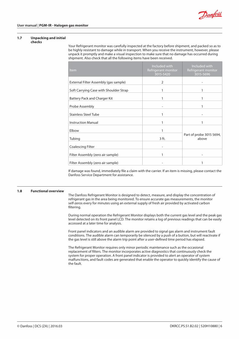
Your Refrigerant monitor was carefully inspected at the factory before shipment, and packed so as to be highly resistant to damage while in transport. When you receive the instrument, however, please unpack it promptly and make a visual inspection to make sure that no damage has occurred during shipment. Also check that all the following items have been received.
ItemIncluded with
Refrigerant monitor 3015-5420
Included with Refrigerant monitor
3015-5696
External Filter Assembly (gas sample) 2 -
Soft Carrying Case with Shoulder Strap 1 1
Battery Pack and Charger Kit 1 1
Probe Assembly - 1
Stainless Steel Tube 1 -
Instruction Manual 1 1
Elbow 1Part of probe 3015 5694,
aboveTubing 3 ft.
Coalescing Filter -
Filter Assembly (zero air sample) 1 -
Filter Assembly (zero air sample) - 1
If damage was found, immediately file a claim with the carrier. If an item is missing, please contact the Danfoss Service Department for assistance.
1.8 Functional overviewThe Danfoss Refrigerant Monitor is designed to detect, measure, and display the concentration of refrigerant gas in the area being monitored. To ensure accurate gas measurements, the monitor self-zeros every for minutes using an external supply of fresh air provided by activated carbon filtering.
During normal operation the Refrigerant Monitor displays both the current gas level and the peak gas level detected on its front panel LCD. The monitor retains a log of previous readings that can be easily accessed at a later time for analysis.
Front panel indicators and an audible alarm are provided to signal gas alarm and instrument fault conditions. The audible alarm can temporarily be silenced by a push of a button, but will reactivate if the gas level is still above the alarm trip point after a user-defined time period has elapsed.
The Refrigerant Monitor requires only minor periodic maintenance such as the occasional replacement of filters. The monitor incorporates active diagnostics that continuously check the system for proper operation. A front panel indicator is provided to alert an operator of system malfunctions, and fault codes are generated that enable the operator to quickly identify the cause of the fault.
User manual | PGM-IR - Halogen gas monitor
© Danfoss | DCS (ZA) | 2016.03 DKRCC.PS.S1.B2.02 | 520H10880 | 6
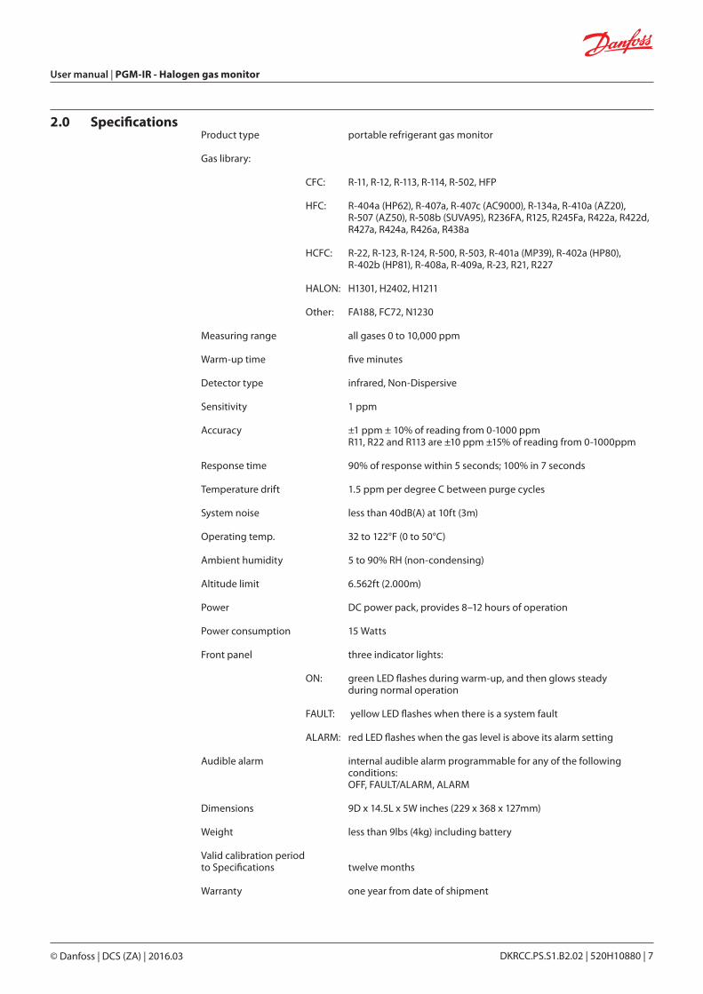
2.0 SpecificationsProduct type portable refrigerant gas monitor
Gas library:
CFC: R-11, R-12, R-113, R-114, R-502, HFP
HFC: R-404a (HP62), R-407a, R-407c (AC9000), R-134a, R-410a (AZ20), R-507 (AZ50), R-508b (SUVA95), R236FA, R125, R245Fa, R422a, R422d, R427a, R424a, R426a, R438a
HCFC: R-22, R-123, R-124, R-500, R-503, R-401a (MP39), R-402a (HP80), R-402b (HP81), R-408a, R-409a, R-23, R21, R227
HALON: H1301, H2402, H1211
Other: FA188, FC72, N1230
Measuring range all gases 0 to 10,000 ppm
Warm-up time five minutes
Detector type infrared, Non-Dispersive
Sensitivity 1 ppm
Accuracy ±1 ppm ± 10% of reading from 0-1000 ppm R11, R22 and R113 are ±10 ppm ±15% of reading from 0-1000ppm
Response time 90% of response within 5 seconds; 100% in 7 seconds
Temperature drift 1.5 ppm per degree C between purge cycles
System noise less than 40dB(A) at 10ft (3m)
Operating temp. 32 to 122°F (0 to 50°C)
Ambient humidity 5 to 90% RH (non-condensing)
Altitude limit 6.562ft (2.000m)
Power DC power pack, provides 8–12 hours of operation
Power consumption 15 Watts
Front panel three indicator lights:
ON: green LED flashes during warm-up, and then glows steady during normal operation
FAULT: yellow LED flashes when there is a system fault
ALARM: red LED flashes when the gas level is above its alarm setting
Audible alarm internal audible alarm programmable for any of the following conditions: OFF, FAULT/ALARM, ALARM
Dimensions 9D x 14.5L x 5W inches (229 x 368 x 127mm)
Weight less than 9lbs (4kg) including battery
Valid calibration period to Specifications twelve months
Warranty one year from date of shipment
User manual | PGM-IR - Halogen gas monitor
© Danfoss | DCS (ZA) | 2016.03 DKRCC.PS.S1.B2.02 | 520H10880 | 7
3.0 Operation
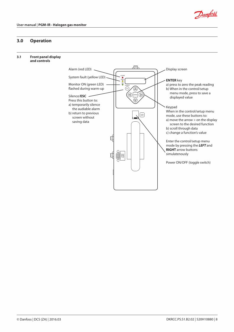
3.1 Front panel display and controls
Alarm (red LED) Display screen
ENTER keya) press to zero the peak readingb) When in the control/setup menu mode, press to save a displayed value
KeypadWhen in the control/setup menumode, use these buttons to:a) move the arrow > on the display screen to the desired functionb) scroll through datac) change a function’s value
Enter the control/setup menumode by pressing the LEFT andRIGHT arrow buttonssimulatenously
Power ON/OFF (toggle switch)
System fault (yellow LED)
Monitor ON (green LED)�ashed during warm-up
Silence/ESCPress this button to:a) temporarily silence the audiable alarmb) return to previous screen without saving data
ENTER
ESC
SILENCE
ALARM
FAULT
ON
I/O
DATA
ON
LY
User manual | PGM-IR - Halogen gas monitor
© Danfoss | DCS (ZA) | 2016.03 DKRCC.PS.S1.B2.02 | 520H10880 | 8
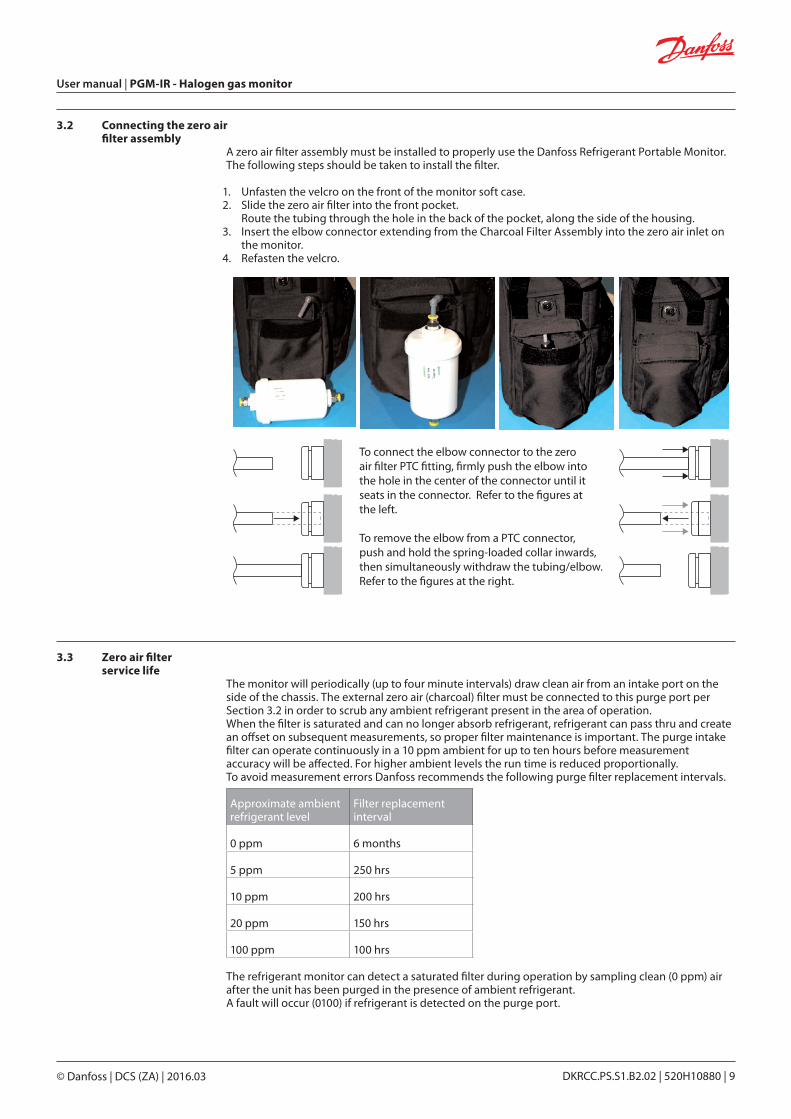
3.2 Connecting the zero air filter assembly
A zero air filter assembly must be installed to properly use the Danfoss Refrigerant Portable Monitor.The following steps should be taken to install the filter.
1. Unfasten the velcro on the front of the monitor soft case.2. Slide the zero air filter into the front pocket.
Route the tubing through the hole in the back of the pocket, along the side of the housing.3. Insert the elbow connector extending from the Charcoal Filter Assembly into the zero air inlet on
the monitor.4. Refasten the velcro.
To connect the elbow connector to the zeroair �lter PTC �tting, �rmly push the elbow intothe hole in the center of the connector until itseats in the connector. Refer to the �gures atthe left.
To remove the elbow from a PTC connector,push and hold the spring-loaded collar inwards,then simultaneously withdraw the tubing/elbow.Refer to the �gures at the right.
3.3 Zero air filter service life
The monitor will periodically (up to four minute intervals) draw clean air from an intake port on the side of the chassis. The external zero air (charcoal) filter must be connected to this purge port per Section 3.2 in order to scrub any ambient refrigerant present in the area of operation. When the filter is saturated and can no longer absorb refrigerant, refrigerant can pass thru and create an offset on subsequent measurements, so proper filter maintenance is important. The purge intake filter can operate continuously in a 10 ppm ambient for up to ten hours before measurement accuracy will be affected. For higher ambient levels the run time is reduced proportionally. To avoid measurement errors Danfoss recommends the following purge filter replacement intervals.
Approximate ambient refrigerant level
Filter replacement interval
0 ppm 6 months
5 ppm 250 hrs
10 ppm 200 hrs
20 ppm 150 hrs
100 ppm 100 hrs
The refrigerant monitor can detect a saturated filter during operation by sampling clean (0 ppm) air after the unit has been purged in the presence of ambient refrigerant. A fault will occur (0100) if refrigerant is detected on the purge port.
User manual | PGM-IR - Halogen gas monitor
© Danfoss | DCS (ZA) | 2016.03 DKRCC.PS.S1.B2.02 | 520H10880 | 9
3.4 Connecting gas-sample, exhaust and purge lines
3.4.1 OverviewA single gas-sample line needs to be run from the Refrigerant Monitor to the area to be monitored. If desired, an optional exhaust line can be installed to vent refrigerant gas away from the monitor.
3.4.2 Connecting the gas-sample line or probe
To connect the gas-sample line to the monitor, simply push the tubing onto the elbow connector and attach the elbow to the Gas Sample Port on the front of the monitor as shown in the illustration below.
The gas-sample line can be up to 50ft (15.2m) in length. All tubing bends should have a radius of no less than 5" to insure proper airflow. If kinks or obstructions occur in the line the monitor may not function properly.
NOTE: every foot of tubing added to the sample probe increases the instrument response time by 1 second. For best performance use the tubing provided with the instrument when possible
The end of this line should be placed near the potential leak source and positioned to reduce the possibility of mists, aerosols, oil, water, dust, or other contaminates being drawn into the monitor.
An external filter should be attached to the end of this line. (See the figure "Connecting the gas sample line or probe").
3.4.3 Connecting the gas-sample probe
If refrigerant monitor was ordered the probe assembly is provided pre-assembled. Simply connect the elbow to the gas sample port. (See the figure "Connecting the gas sample line or probe").
User manual | PGM-IR - Halogen gas monitor
© Danfoss | DCS (ZA) | 2016.03 DKRCC.PS.S1.B2.02 | 520H10880 | 10
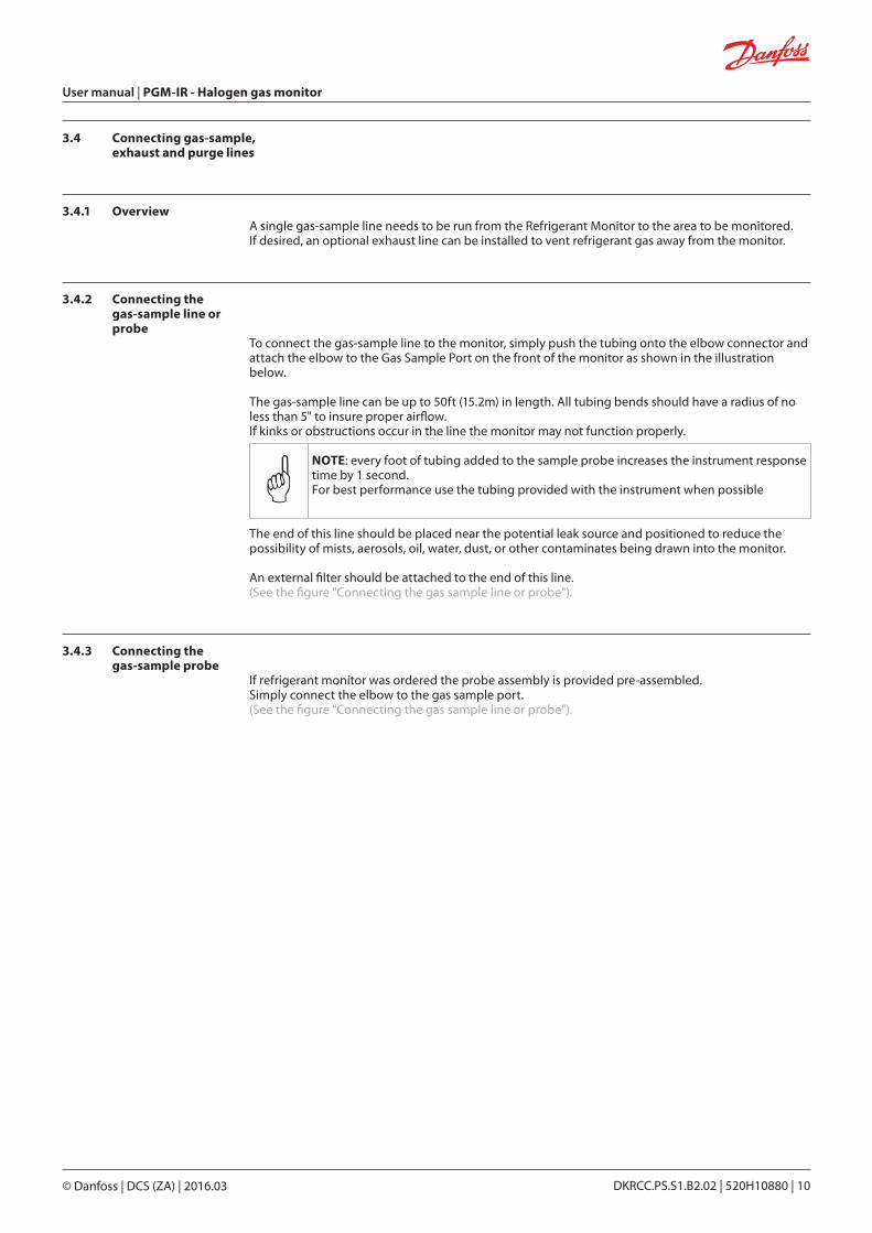
3.4.4 Connecting the exhaust line
The optional exhaust line carries the exhausted gas sample away from the monitor. The exhaust line can be up to 50ft (15.2m) in length. Ideally this line should terminate outdoors in a location that is not exposed to the elements.
Connecting the gas sample line or probe
Probe assembly withreplacement �lter
Filter element assembly
Stainless steeltube or
Powerswitch
Gas sample tubing50 foot (max)
Gas sampleport
Zero airinlet port
Exhaustport
Battery packconnector
Connect the exhaust line to the monitor by firmly pushing the tubing into the Exhaust Port’s push-to-connect (PTC) fitting. If the exhaust line terminates outside the building, position the tubing so that no water or moisture can enter the line.
NOTE: this line does not require a termination filter
To connect the exhaust line to the exhaust port’sPTC �tting, �rmly push the appropriate tubing intothe hole in the center of the connector until it seatsin the connector. Refer to the �gures at the left.
To remove tubing from a PTC connector, push andhold the spring-loaded collar inwards, thensimultaneously withdraw the tubing.Refer to the �gures at the right.
User manual | PGM-IR - Halogen gas monitor
© Danfoss | DCS (ZA) | 2016.03 DKRCC.PS.S1.B2.02 | 520H10880 | 11
3.4.5 Connecting zero air inlet to an external purge line (optional)
If using the charcoal filter assembly a purge line is not required.
The purge line provides the same function as the charcoal filter, supplying clean air (0 ppm target gas concentration) into the monitor for the purpose of purging the monitor and setting its baseline reading.
The zero air inlet can be up to 50ft (15.2m) in length. This line should terminate in an area known to contain clean (0 ppm) air. To connect the purge line to the monitor, simply push the tubing into the Purge Air Inlet Port. If the purge line terminates outside the building, position the tubing so that no water or moisture can enter the line.
3.5 Gas detector operation
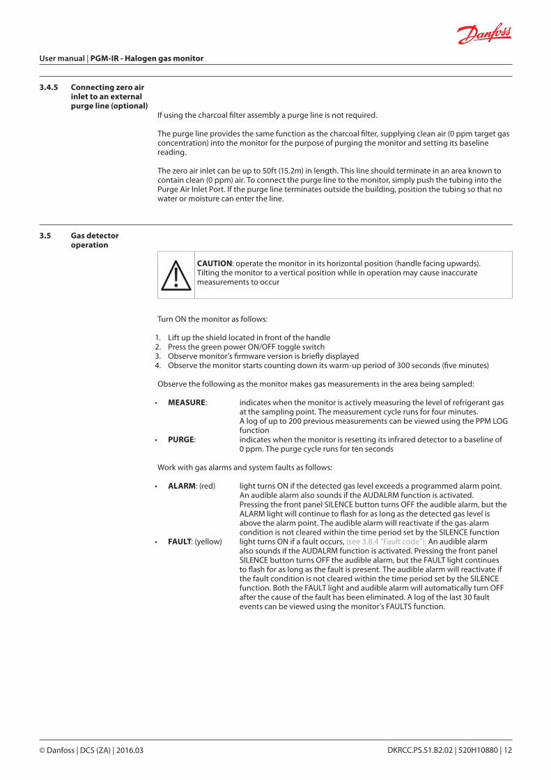
!CAUTION: operate the monitor in its horizontal position (handle facing upwards). Tilting the monitor to a vertical position while in operation may cause inaccurate measurements to occur
Turn ON the monitor as follows:
1. Lift up the shield located in front of the handle2. Press the green power ON/OFF toggle switch3. Observe monitor’s firmware version is briefly displayed4. Observe the monitor starts counting down its warm-up period of 300 seconds (five minutes)
Observe the following as the monitor makes gas measurements in the area being sampled:
• MEASURE: indicates when the monitor is actively measuring the level of refrigerant gas at the sampling point. The measurement cycle runs for four minutes. A log of up to 200 previous measurements can be viewed using the PPM LOG function
• PURGE: indicates when the monitor is resetting its infrared detector to a baseline of 0 ppm. The purge cycle runs for ten seconds
Work with gas alarms and system faults as follows:
• ALARM: (red) light turns ON if the detected gas level exceeds a programmed alarm point. An audible alarm also sounds if the AUDALRM function is activated. Pressing the front panel SILENCE button turns OFF the audible alarm, but the ALARM light will continue to flash for as long as the detected gas level is above the alarm point. The audible alarm will reactivate if the gas-alarm condition is not cleared within the time period set by the SILENCE function
• FAULT: (yellow) light turns ON if a fault occurs, (see 3.8.4 "Fault code"). An audible alarm also sounds if the AUDALRM function is activated. Pressing the front panel SILENCE button turns OFF the audible alarm, but the FAULT light continues to flash for as long as the fault is present. The audible alarm will reactivate if the fault condition is not cleared within the time period set by the SILENCE function. Both the FAULT light and audible alarm will automatically turn OFF after the cause of the fault has been eliminated. A log of the last 30 fault events can be viewed using the monitor’s FAULTS function.
User manual | PGM-IR - Halogen gas monitor
© Danfoss | DCS (ZA) | 2016.03 DKRCC.PS.S1.B2.02 | 520H10880 | 12
3.6 Battery charging and using
3.6.1 Charging the batteryThe monitor is powered by a rechargeable battery pack located in a pouch on the side of the monitor’s soft carrying case. The battery pack can be recharged at any time, regardless of the battery’s current charge state.
The AC adapter provided accepts voltage inputs of 100 to 240VAC. Plug the adapter into the wall, then into the battery. Disconnect the adapter when the battery is fully charged. A fully charged battery pack will power the monitor for approximately 8-12 hours.
3.6.2 Using the batteryThe PGM is designed for a 16VDC input. Following the instructions for the particular battery in use, set the output voltage to 16V. Plug the battery into the instrument's battery input port and the instrument is ready for use.
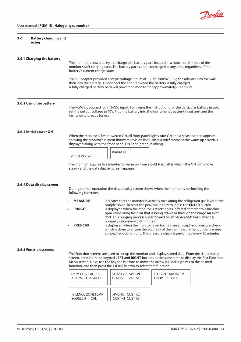
3.6.3 Initial power ONWhen the monitor is first powered ON, all front panel lights turn ON and a splash screen appears showing the monitor’s current firmware revision level. After a brief moment the warm up screen is displayed along with the front panel ON light (green) blinking.
VERSION x.xxWARM UP
The monitor requires five minutes to warm up from a cold start; after which, the ON light glows steady and the data display screen appears.
3.6.4 Data display screenDuring normal operation the data display screen shows when the monitor is performing the following functions:
• MEASURE: indicates that the monitor is actively measuring the refrigerant gas level at the sample point. To reset the peak value to zero, press the ENTER button
• PURGE: is displayed when the monitor is resetting its infrared detector to a baseline ppm value using fresh air that is being drawn in through the Purge Air Inlet Port. This purging process is performed on an "as needed" basis, which is normally once every 6-8 minutes
• PRES CHK: is displayed when the monitor is performing an atmospheric pressure check, which is done to ensure the accuracy of the gas measurement under varying atmospheric conditions. This pressure check is performed every 30 minutes
3.6.5 Function screensThe Function screens are used to set up the monitor and display stored data. From the data display screen, press both the Keypad LEFT and RIGHT buttons at the same time to display the first Function Menu screen. Next, use the Keypad buttons to move the arrow (>) until it points to the desired function, and then press the ENTER button to select that function.
>PPM LOG FAULTS ALARMS DIAGNOS
>GASTYPE SPILLVL LEAKLVL EVACLVL
>LOG INT AUDALRM LOOP CLOCK
>SILENCE ZONETEMP SQUELCH CAL
>P-CHK CUST K2 CUST K1 CUST K3
User manual | PGM-IR - Halogen gas monitor
© Danfoss | DCS (ZA) | 2016.03 DKRCC.PS.S1.B2.02 | 520H10880 | 13
Once a function has been selected, use the Keypad to scroll through the displayed data or to change a parameter associated with that function. Press ENTER to save any newly entered parameters. Press the ESC button to return to the previous screen without saving.
NOTE: that if no buttons are pressed within 90 seconds after selecting a function, the unit returns to the data display screen
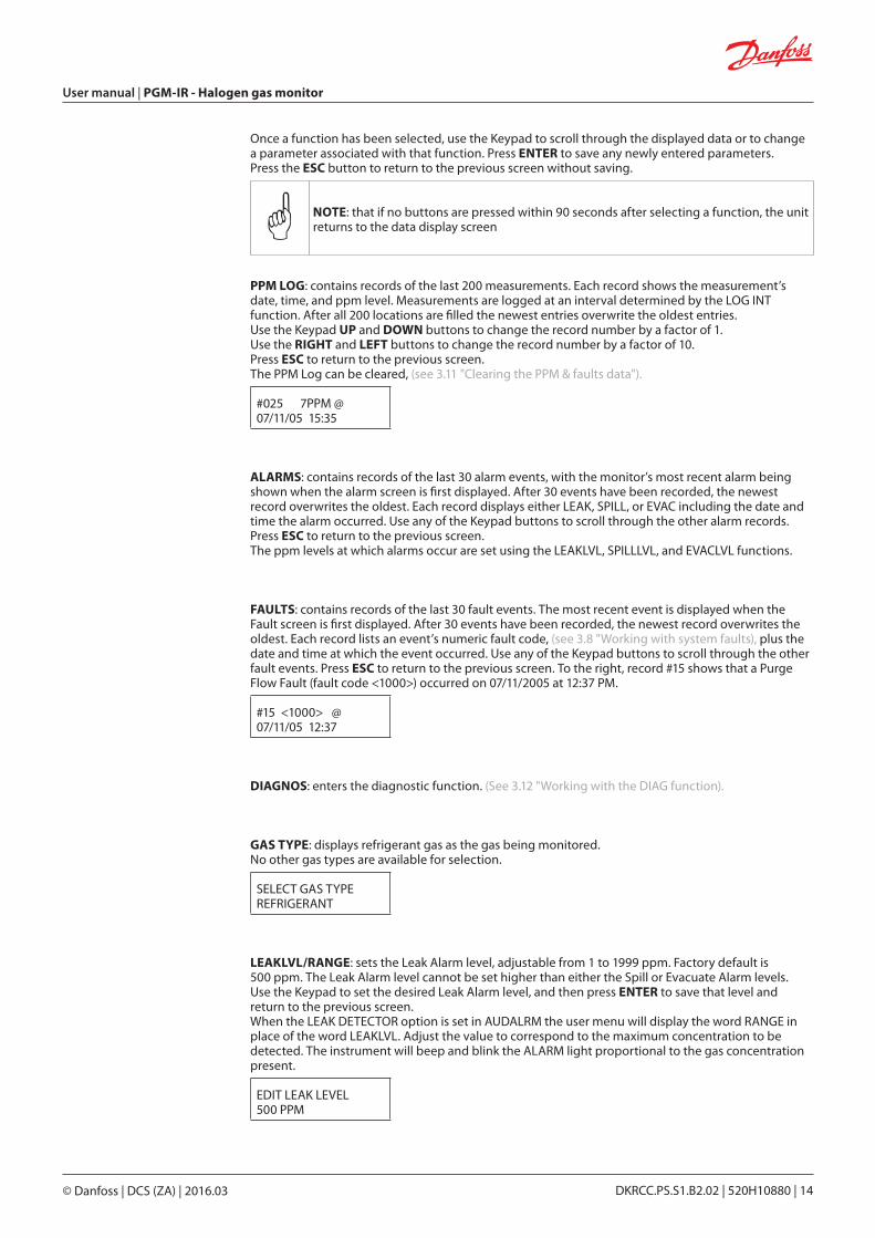
PPM LOG: contains records of the last 200 measurements. Each record shows the measurement’s date, time, and ppm level. Measurements are logged at an interval determined by the LOG INT function. After all 200 locations are filled the newest entries overwrite the oldest entries. Use the Keypad UP and DOWN buttons to change the record number by a factor of 1. Use the RIGHT and LEFT buttons to change the record number by a factor of 10. Press ESC to return to the previous screen. The PPM Log can be cleared, (see 3.11 "Clearing the PPM & faults data").
#025 7PPM @07/11/05 15:35
ALARMS: contains records of the last 30 alarm events, with the monitor’s most recent alarm being shown when the alarm screen is first displayed. After 30 events have been recorded, the newest record overwrites the oldest. Each record displays either LEAK, SPILL, or EVAC including the date and time the alarm occurred. Use any of the Keypad buttons to scroll through the other alarm records.Press ESC to return to the previous screen. The ppm levels at which alarms occur are set using the LEAKLVL, SPILLLVL, and EVACLVL functions.
FAULTS: contains records of the last 30 fault events. The most recent event is displayed when the Fault screen is first displayed. After 30 events have been recorded, the newest record overwrites the oldest. Each record lists an event’s numeric fault code, (see 3.8 "Working with system faults), plus the date and time at which the event occurred. Use any of the Keypad buttons to scroll through the other fault events. Press ESC to return to the previous screen. To the right, record #15 shows that a Purge Flow Fault (fault code <1000>) occurred on 07/11/2005 at 12:37 PM.
#15 <1000> @07/11/05 12:37
DIAGNOS: enters the diagnostic function. (See 3.12 "Working with the DIAG function).
GAS TYPE: displays refrigerant gas as the gas being monitored. No other gas types are available for selection.
SELECT GAS TYPEREFRIGERANT
LEAKLVL/RANGE: sets the Leak Alarm level, adjustable from 1 to 1999 ppm. Factory default is 500 ppm. The Leak Alarm level cannot be set higher than either the Spill or Evacuate Alarm levels. Use the Keypad to set the desired Leak Alarm level, and then press ENTER to save that level and return to the previous screen. When the LEAK DETECTOR option is set in AUDALRM the user menu will display the word RANGE in place of the word LEAKLVL. Adjust the value to correspond to the maximum concentration to be detected. The instrument will beep and blink the ALARM light proportional to the gas concentration present.
EDIT LEAK LEVEL500 PPM
User manual | PGM-IR - Halogen gas monitor
© Danfoss | DCS (ZA) | 2016.03 DKRCC.PS.S1.B2.02 | 520H10880 | 14
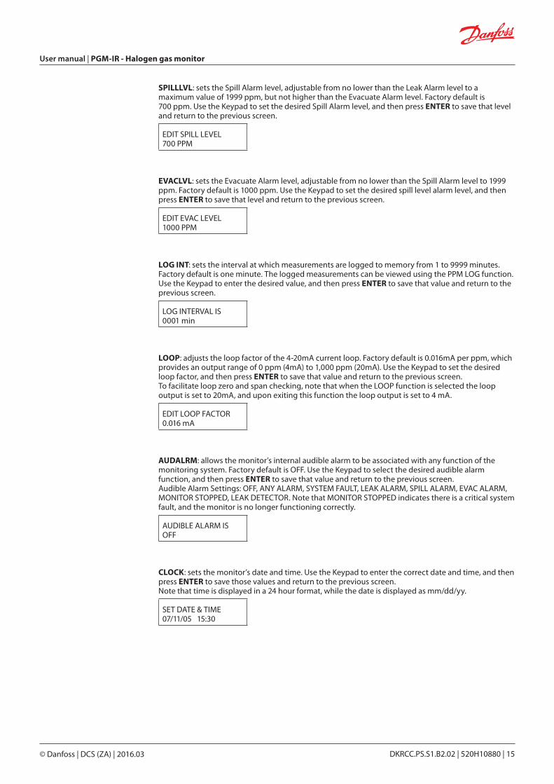
SPILLLVL: sets the Spill Alarm level, adjustable from no lower than the Leak Alarm level to a maximum value of 1999 ppm, but not higher than the Evacuate Alarm level. Factory default is 700 ppm. Use the Keypad to set the desired Spill Alarm level, and then press ENTER to save that level and return to the previous screen.
EDIT SPILL LEVEL 700 PPM
EVACLVL: sets the Evacuate Alarm level, adjustable from no lower than the Spill Alarm level to 1999 ppm. Factory default is 1000 ppm. Use the Keypad to set the desired spill level alarm level, and then press ENTER to save that level and return to the previous screen.
EDIT EVAC LEVEL1000 PPM
LOG INT: sets the interval at which measurements are logged to memory from 1 to 9999 minutes. Factory default is one minute. The logged measurements can be viewed using the PPM LOG function. Use the Keypad to enter the desired value, and then press ENTER to save that value and return to the previous screen.
LOG INTERVAL IS0001 min
LOOP: adjusts the loop factor of the 4-20mA current loop. Factory default is 0.016mA per ppm, which provides an output range of 0 ppm (4mA) to 1,000 ppm (20mA). Use the Keypad to set the desired loop factor, and then press ENTER to save that value and return to the previous screen. To facilitate loop zero and span checking, note that when the LOOP function is selected the loop output is set to 20mA, and upon exiting this function the loop output is set to 4 mA.
EDIT LOOP FACTOR0.016 mA
AUDALRM: allows the monitor’s internal audible alarm to be associated with any function of the monitoring system. Factory default is OFF. Use the Keypad to select the desired audible alarm function, and then press ENTER to save that value and return to the previous screen. Audible Alarm Settings: OFF, ANY ALARM, SYSTEM FAULT, LEAK ALARM, SPILL ALARM, EVAC ALARM, MONITOR STOPPED, LEAK DETECTOR. Note that MONITOR STOPPED indicates there is a critical system fault, and the monitor is no longer functioning correctly.
AUDIBLE ALARM ISOFF
CLOCK: sets the monitor’s date and time. Use the Keypad to enter the correct date and time, and then press ENTER to save those values and return to the previous screen. Note that time is displayed in a 24 hour format, while the date is displayed as mm/dd/yy.
SET DATE & TIME07/11/05 15:30
User manual | PGM-IR - Halogen gas monitor
© Danfoss | DCS (ZA) | 2016.03 DKRCC.PS.S1.B2.02 | 520H10880 | 15
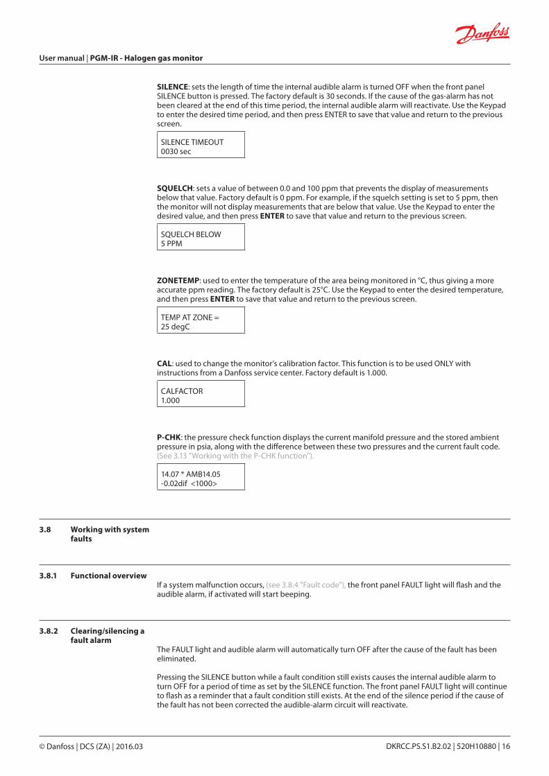
SILENCE: sets the length of time the internal audible alarm is turned OFF when the front panel SILENCE button is pressed. The factory default is 30 seconds. If the cause of the gas-alarm has not been cleared at the end of this time period, the internal audible alarm will reactivate. Use the Keypad to enter the desired time period, and then press ENTER to save that value and return to the previous screen.
SILENCE TIMEOUT0030 sec
SQUELCH: sets a value of between 0.0 and 100 ppm that prevents the display of measurements below that value. Factory default is 0 ppm. For example, if the squelch setting is set to 5 ppm, then the monitor will not display measurements that are below that value. Use the Keypad to enter the desired value, and then press ENTER to save that value and return to the previous screen.
SQUELCH BELOW5 PPM
ZONETEMP: used to enter the temperature of the area being monitored in °C, thus giving a more accurate ppm reading. The factory default is 25°C. Use the Keypad to enter the desired temperature, and then press ENTER to save that value and return to the previous screen.
TEMP AT ZONE =25 degC
CAL: used to change the monitor’s calibration factor. This function is to be used ONLY with instructions from a Danfoss service center. Factory default is 1.000.
CALFACTOR1.000
P-CHK: the pressure check function displays the current manifold pressure and the stored ambient pressure in psia, along with the difference between these two pressures and the current fault code. (See 3.13 "Working with the P-CHK function").
14.07 * AMB14.05-0.02dif <1000>
3.8 Working with system faults
3.8.1 Functional overviewIf a system malfunction occurs, (see 3.8.4 "Fault code"), the front panel FAULT light will flash and the audible alarm, if activated will start beeping.
3.8.2 Clearing/silencing a fault alarm
The FAULT light and audible alarm will automatically turn OFF after the cause of the fault has been eliminated.
Pressing the SILENCE button while a fault condition still exists causes the internal audible alarm to turn OFF for a period of time as set by the SILENCE function. The front panel FAULT light will continue to flash as a reminder that a fault condition still exists. At the end of the silence period if the cause of the fault has not been corrected the audible-alarm circuit will reactivate.
User manual | PGM-IR - Halogen gas monitor
© Danfoss | DCS (ZA) | 2016.03 DKRCC.PS.S1.B2.02 | 520H10880 | 16
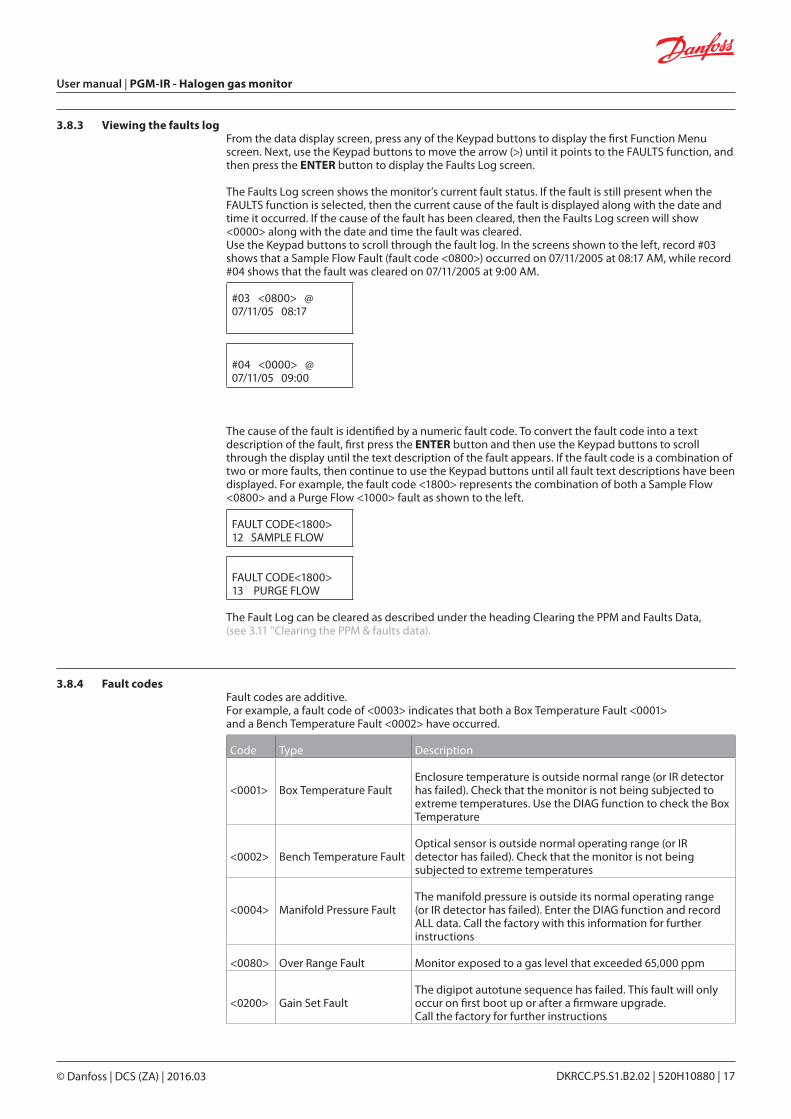
3.8.3 Viewing the faults logFrom the data display screen, press any of the Keypad buttons to display the first Function Menu screen. Next, use the Keypad buttons to move the arrow (>) until it points to the FAULTS function, and then press the ENTER button to display the Faults Log screen.
The Faults Log screen shows the monitor’s current fault status. If the fault is still present when the FAULTS function is selected, then the current cause of the fault is displayed along with the date and time it occurred. If the cause of the fault has been cleared, then the Faults Log screen will show <0000> along with the date and time the fault was cleared. Use the Keypad buttons to scroll through the fault log. In the screens shown to the left, record #03 shows that a Sample Flow Fault (fault code <0800>) occurred on 07/11/2005 at 08:17 AM, while record #04 shows that the fault was cleared on 07/11/2005 at 9:00 AM.
#03 <0800> @07/11/05 08:17
#04 <0000> @07/11/05 09:00
The cause of the fault is identified by a numeric fault code. To convert the fault code into a text description of the fault, first press the ENTER button and then use the Keypad buttons to scroll through the display until the text description of the fault appears. If the fault code is a combination of two or more faults, then continue to use the Keypad buttons until all fault text descriptions have been displayed. For example, the fault code <1800> represents the combination of both a Sample Flow <0800> and a Purge Flow <1000> fault as shown to the left.
FAULT CODE<1800>12 SAMPLE FLOW
FAULT CODE<1800>13 PURGE FLOW
The Fault Log can be cleared as described under the heading Clearing the PPM and Faults Data, (see 3.11 "Clearing the PPM & faults data).
3.8.4 Fault codesFault codes are additive. For example, a fault code of <0003> indicates that both a Box Temperature Fault <0001> and a Bench Temperature Fault <0002> have occurred.
Code Type Description
<0001> Box Temperature FaultEnclosure temperature is outside normal range (or IR detector has failed). Check that the monitor is not being subjected to extreme temperatures. Use the DIAG function to check the Box Temperature
<0002> Bench Temperature FaultOptical sensor is outside normal operating range (or IR detector has failed). Check that the monitor is not being subjected to extreme temperatures
<0004> Manifold Pressure FaultThe manifold pressure is outside its normal operating range (or IR detector has failed). Enter the DIAG function and record ALL data. Call the factory with this information for further instructions
<0080> Over Range Fault Monitor exposed to a gas level that exceeded 65,000 ppm
<0200> Gain Set FaultThe digipot autotune sequence has failed. This fault will only occur on first boot up or after a firmware upgrade. Call the factory for further instructions
User manual | PGM-IR - Halogen gas monitor
© Danfoss | DCS (ZA) | 2016.03 DKRCC.PS.S1.B2.02 | 520H10880 | 17
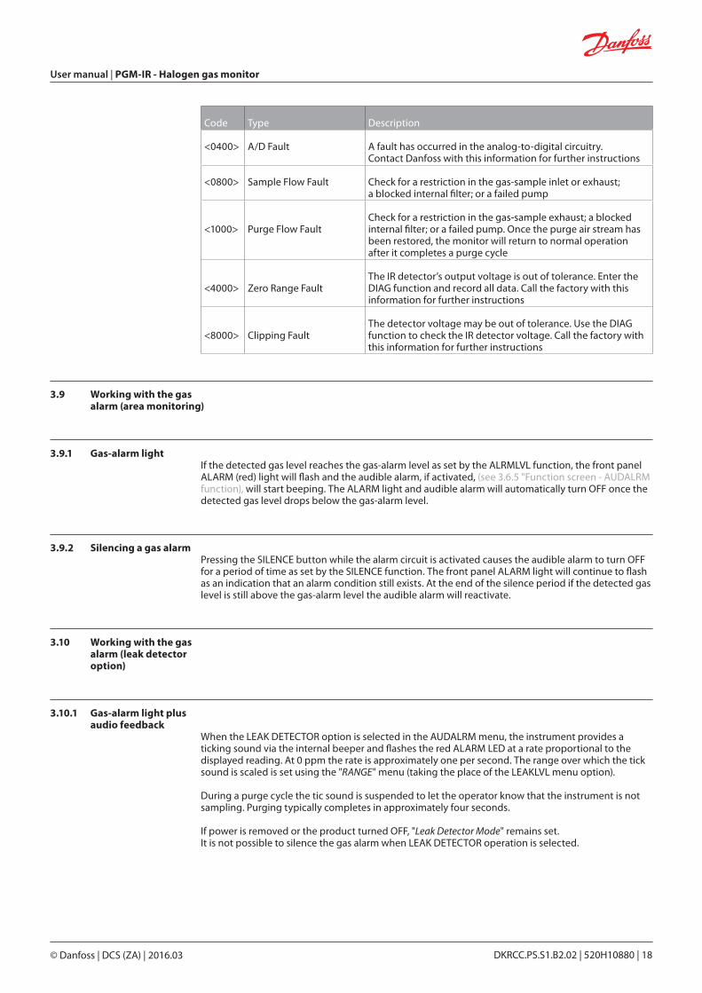
Code Type Description
<0400> A/D Fault A fault has occurred in the analog-to-digital circuitry. Contact Danfoss with this information for further instructions
<0800> Sample Flow Fault Check for a restriction in the gas-sample inlet or exhaust; a blocked internal filter; or a failed pump
<1000> Purge Flow FaultCheck for a restriction in the gas-sample exhaust; a blocked internal filter; or a failed pump. Once the purge air stream has been restored, the monitor will return to normal operation after it completes a purge cycle
<4000> Zero Range FaultThe IR detector’s output voltage is out of tolerance. Enter the DIAG function and record all data. Call the factory with this information for further instructions
<8000> Clipping FaultThe detector voltage may be out of tolerance. Use the DIAG function to check the IR detector voltage. Call the factory with this information for further instructions
3.9 Working with the gas alarm (area monitoring)
3.9.1 Gas-alarm lightIf the detected gas level reaches the gas-alarm level as set by the ALRMLVL function, the front panel ALARM (red) light will flash and the audible alarm, if activated, (see 3.6.5 "Function screen - AUDALRM function), will start beeping. The ALARM light and audible alarm will automatically turn OFF once the detected gas level drops below the gas-alarm level.
3.9.2 Silencing a gas alarmPressing the SILENCE button while the alarm circuit is activated causes the audible alarm to turn OFF for a period of time as set by the SILENCE function. The front panel ALARM light will continue to flash as an indication that an alarm condition still exists. At the end of the silence period if the detected gas level is still above the gas-alarm level the audible alarm will reactivate.
3.10 Working with the gas alarm (leak detector option)
3.10.1 Gas-alarm light plus audio feedback
When the LEAK DETECTOR option is selected in the AUDALRM menu, the instrument provides a ticking sound via the internal beeper and flashes the red ALARM LED at a rate proportional to the displayed reading. At 0 ppm the rate is approximately one per second. The range over which the tick sound is scaled is set using the "RANGE" menu (taking the place of the LEAKLVL menu option).
During a purge cycle the tic sound is suspended to let the operator know that the instrument is not sampling. Purging typically completes in approximately four seconds.
If power is removed or the product turned OFF, "Leak Detector Mode" remains set. It is not possible to silence the gas alarm when LEAK DETECTOR operation is selected.
User manual | PGM-IR - Halogen gas monitor
© Danfoss | DCS (ZA) | 2016.03 DKRCC.PS.S1.B2.02 | 520H10880 | 18
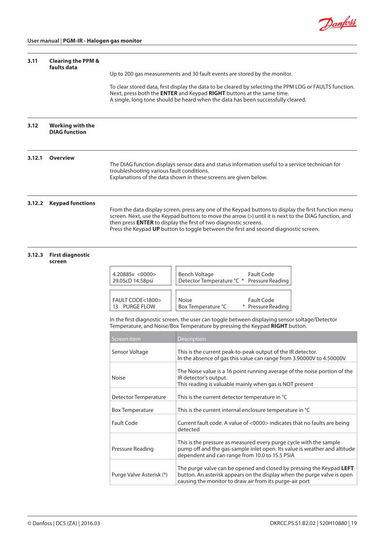
3.11 Clearing the PPM & faults data
Up to 200 gas measurements and 30 fault events are stored by the monitor.
To clear stored data, first display the data to be cleared by selecting the PPM LOG or FAULTS function. Next, press both the ENTER and Keypad RIGHT buttons at the same time. A single, long tone should be heard when the data has been successfully cleared.
3.12 Working with the DIAG function
3.12.1 OverviewThe DIAG function displays sensor data and status information useful to a service technician for troubleshooting various fault conditions. Explanations of the data shown in these screens are given below.
3.12.2 Keypad functionsFrom the data display screen, press any one of the Keypad buttons to display the first function menu screen. Next, use the Keypad buttons to move the arrow (>) until it is next to the DIAG function, and then press ENTER to display the first of two diagnostic screens. Press the Keypad UP button to toggle between the first and second diagnostic screen.
3.12.3 First diagnostic screen
4.20885v <0000>29.05cD 14.58psi
Bench Voltage Fault CodeDetector Temperature °C * Pressure Reading
FAULT CODE<1800>13 PURGE FLOW
Noise Fault CodeBox Temperature °C * Pressure Reading
In the first diagnostic screen, the user can toggle between displaying sensor soltage/Detector Temperature, and Noise/Box Temperature by pressing the Keypad RIGHT button.
Screen Item Description
Sensor Voltage This is the current peak-to-peak output of the IR detector. In the absence of gas this value can range from 3.90000V to 4.50000V
NoiseThe Noise value is a 16 point running average of the noise portion of the IR detector’s output. This reading is valuable mainly when gas is NOT present
Detector Temperature This is the current detector temperature in °C
Box Temperature This is the current internal enclosure temperature in °C
Fault Code Current fault code. A value of <0000> indicates that no faults are being detected
Pressure ReadingThis is the pressure as measured every purge cycle with the sample pump off and the gas-sample inlet open. Its value is weather and altitude dependent and can range from 10.0 to 15.5 PSIA
Purge Valve Asterisk (*)The purge valve can be opened and closed by pressing the Keypad LEFT button. An asterisk appears on the display when the purge valve is open causing the monitor to draw air from its purge-air port
User manual | PGM-IR - Halogen gas monitor
© Danfoss | DCS (ZA) | 2016.03 DKRCC.PS.S1.B2.02 | 520H10880 | 19
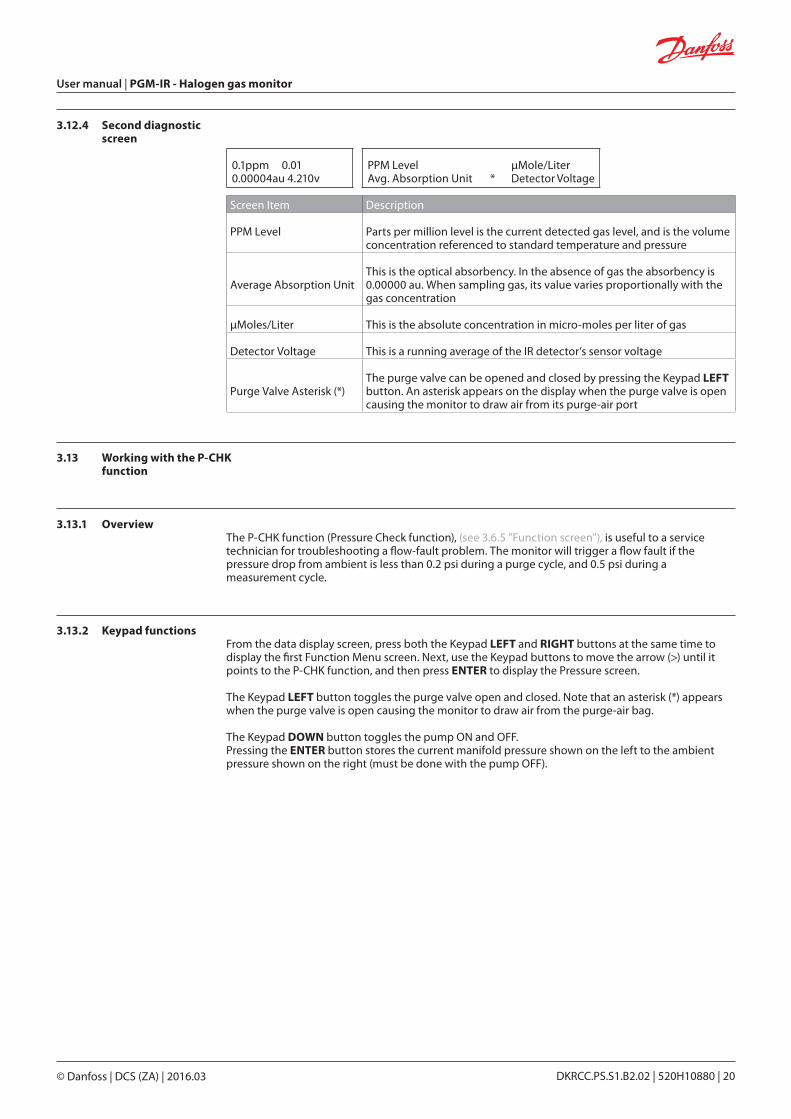
3.12.4 Second diagnostic screen
0.1ppm 0.010.00004au 4.210v
PPM Level µMole/LiterAvg. Absorption Unit * Detector Voltage
Screen Item Description
PPM Level Parts per million level is the current detected gas level, and is the volume concentration referenced to standard temperature and pressure
Average Absorption UnitThis is the optical absorbency. In the absence of gas the absorbency is 0.00000 au. When sampling gas, its value varies proportionally with the gas concentration
µMoles/Liter This is the absolute concentration in micro-moles per liter of gas
Detector Voltage This is a running average of the IR detector’s sensor voltage
Purge Valve Asterisk (*)The purge valve can be opened and closed by pressing the Keypad LEFT button. An asterisk appears on the display when the purge valve is open causing the monitor to draw air from its purge-air port
3.13 Working with the P-CHK function
3.13.1 OverviewThe P-CHK function (Pressure Check function), (see 3.6.5 "Function screen"), is useful to a service technician for troubleshooting a flow-fault problem. The monitor will trigger a flow fault if the pressure drop from ambient is less than 0.2 psi during a purge cycle, and 0.5 psi during a measurement cycle.
3.13.2 Keypad functionsFrom the data display screen, press both the Keypad LEFT and RIGHT buttons at the same time to display the first Function Menu screen. Next, use the Keypad buttons to move the arrow (>) until it points to the P-CHK function, and then press ENTER to display the Pressure screen.
The Keypad LEFT button toggles the purge valve open and closed. Note that an asterisk (*) appears when the purge valve is open causing the monitor to draw air from the purge-air bag.
The Keypad DOWN button toggles the pump ON and OFF. Pressing the ENTER button stores the current manifold pressure shown on the left to the ambient pressure shown on the right (must be done with the pump OFF).
User manual | PGM-IR - Halogen gas monitor
© Danfoss | DCS (ZA) | 2016.03 DKRCC.PS.S1.B2.02 | 520H10880 | 20
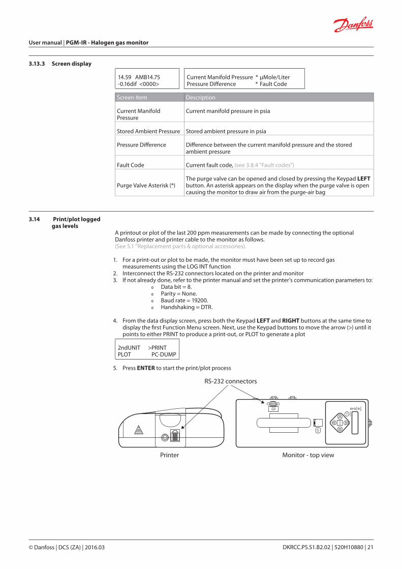
3.13.3 Screen display
14.59 AMB14.75-0.16dif <0000>
Current Manifold Pressure * µMole/LiterPressure Difference * Fault Code
Screen Item Description
Current Manifold Pressure
Current manifold pressure in psia
Stored Ambient Pressure Stored ambient pressure in psia
Pressure Difference Difference between the current manifold pressure and the stored ambient pressure
Fault Code Current fault code, (see 3.8.4 "Fault codes")
Purge Valve Asterisk (*)The purge valve can be opened and closed by pressing the Keypad LEFT button. An asterisk appears on the display when the purge valve is open causing the monitor to draw air from the purge-air bag
3.14 Print/plot logged gas levels
A printout or plot of the last 200 ppm measurements can be made by connecting the optional Danfoss printer and printer cable to the monitor as follows. (See 5.1 "Replacement parts & optional accessories).
1. For a print-out or plot to be made, the monitor must have been set up to record gas measurements using the LOG INT function
2. Interconnect the RS-232 connectors located on the printer and monitor3. If not already done, refer to the printer manual and set the printer’s communication parameters to:
Ř Data bit = 8. Ř Parity = None. Ř Baud rate = 19200. Ř Handshaking = DTR.
4. From the data display screen, press both the Keypad LEFT and RIGHT buttons at the same time to display the first Function Menu screen. Next, use the Keypad buttons to move the arrow (>) until it points to either PRINT to produce a print-out, or PLOT to generate a plot
2ndUNIT >PRINTPLOT PC-DUMP
5. Press ENTER to start the print/plot process
ENTER
ESC
SILENCE
ALA
RM
FAULT
ON
I/O
DATAONLY
RS-232 connectors
Printer Monitor - top view
User manual | PGM-IR - Halogen gas monitor
© Danfoss | DCS (ZA) | 2016.03 DKRCC.PS.S1.B2.02 | 520H10880 | 21
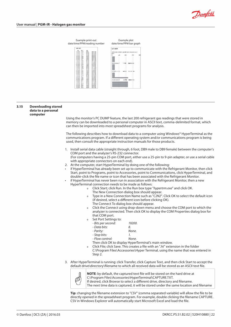
Example print-outdate/time/PPM/reading number
Example plotdate/time/PPM bar graph
3.15 Downloading stored data to a personal computer
Using the monitor’s PC DUMP feature, the last 200 refrigerant gas readings that were stored in memory can be downloaded to a personal computer in ASCII text, comma-delimited format, which can then be imported into most spreadsheet programs for analysis.
The following describes how to download data to a computer using Windows® HyperTerminal as the communications program. If a different operating system and/or communications program is being used, then consult the appropriate instruction manuals for those products.
1. Install serial data cable (straight through, 6 foot, DB9 male to DB9 female) between the computer’s COM port and the analyzer’s RS-232 connector. (For computers having a 25-pin COM port, either use a 25-pin to 9-pin adapter, or use a serial cable with appropriate connectors on each end).
2. At the computer, start HyperTerminal by doing one of the following: • if HyperTerminal has already been set up to communicate with the Refrigerant Monitor, then click
Start, point to Programs, point to Accessories, point to Communications, click HyperTerminal, and double-click the file name or icon that has been associated with the Refrigerant Monitor.
• if HyperTerminal has never been run in association with the Refrigerant Monitor, then a new HyperTerminal connection needs to be made as follows:
Ř Click Start; click Run. In the Run box type "hypertrm.exe" and click OK. The New Connection dialog box should appear.
Ř Type in a New Connection Name such as "C2N2". Click OK to select the default icon (if desired, select a different icon before clicking OK). The Connect To dialog box should appear.
Ř Click the Connect using drop-down menu and choose the COM port to which the analyzer is connected. Then click OK to display the COM Properties dialog box for that COM port.
Ř Set Port Settings to: - Bits per second: 19200. - Data bits: 8. - Parity: None. - Stop bits: 1. - Flow control: None. Then click OK to display HyperTerminal’s main window.
Ř Click File; click Save. This creates a file with an ".ht" extension in the folder C:\Program Files\Accessories\Hyper Terminal, using the name that was entered in Step 2.
3. After HyperTerminal is running: click Transfer, click Capture Text, and then click Start to accept the default drive\directory\filename to which all received data will be stored as an ASCII text file.
NOTE: by default, the captured text file will be stored on the hard drive at C:\Program Files\Accessories\HyperTerminal\CAPTURE.TXT. If desired, click Browse to select a different drive, directory and filename. The next time data is captured, it will be stored under the same location and filename
Tip: changing the filename extension to "CSV" (comma separated variable) will allow the file to be directly opened in the spreadsheet program. For example, double clicking the filename CAPTURE.CSV in Windows Explorer will automatically start Microsoft Excel and load the file.
User manual | PGM-IR - Halogen gas monitor
© Danfoss | DCS (ZA) | 2016.03 DKRCC.PS.S1.B2.02 | 520H10880 | 22
4. From the data display screen, press both the Keypad LEFT and RIGHT buttons at the same time to display the first Function Menu screen. Next, use the Keypad buttons to move the arrow (>) until it points to PC-DUMP, and then press the ENTER button to begin the download process.
5. Observe that the Refrigerant Monitor’s screen goes blank and that HyperTerminal displays the data as it is being received. After all data has been transmitted, the Refrigerant Monitor re-displays the Function Menu screen.
6. To stop capturing data and save it, click Transfer, click Capture Text, click Stop.7. HyperTerminal and the connection to the Refrigerant Monitor can now be closed.
3.16 Importing saved data into a spreadsheet
A text file that was created, (see 3.15 "Downloading stored data to a personal computer"), can be imported into spreadsheet programs that are capable of importing comma-delimited files.
The following describes how to generate a spreadsheet from a comma-delimited text file using Microsoft Excel. If you are using a different spreadsheet program, then please refer to its instruction manual for information on how to import comma-delimited text files.
Tip: if the text file was saved with the filename extension "CSV" a spreadsheet will automatically be created when that file is opened in Microsoft Excel.
1. Start Microsoft Excel.2. Click File, and then click Open to display the Open dialog box.3. Change the "Files of type:" to Text Files.
Then navigate to the directory containing the text file to be imported.4. Double-click the desired filename to display the Text Import Wizard - Step 1 of 3 dialog box.5. Select the Delimited radio button; then click Next to display the Text Import Wizard -
Step 2 of 3 dialog box.6. Under Delimiters, select the Comma check box.
Then click Next to display the Text Import Wizard - Step 3 of 3 dialog box. Ř Click Finish to create the spreadsheet.
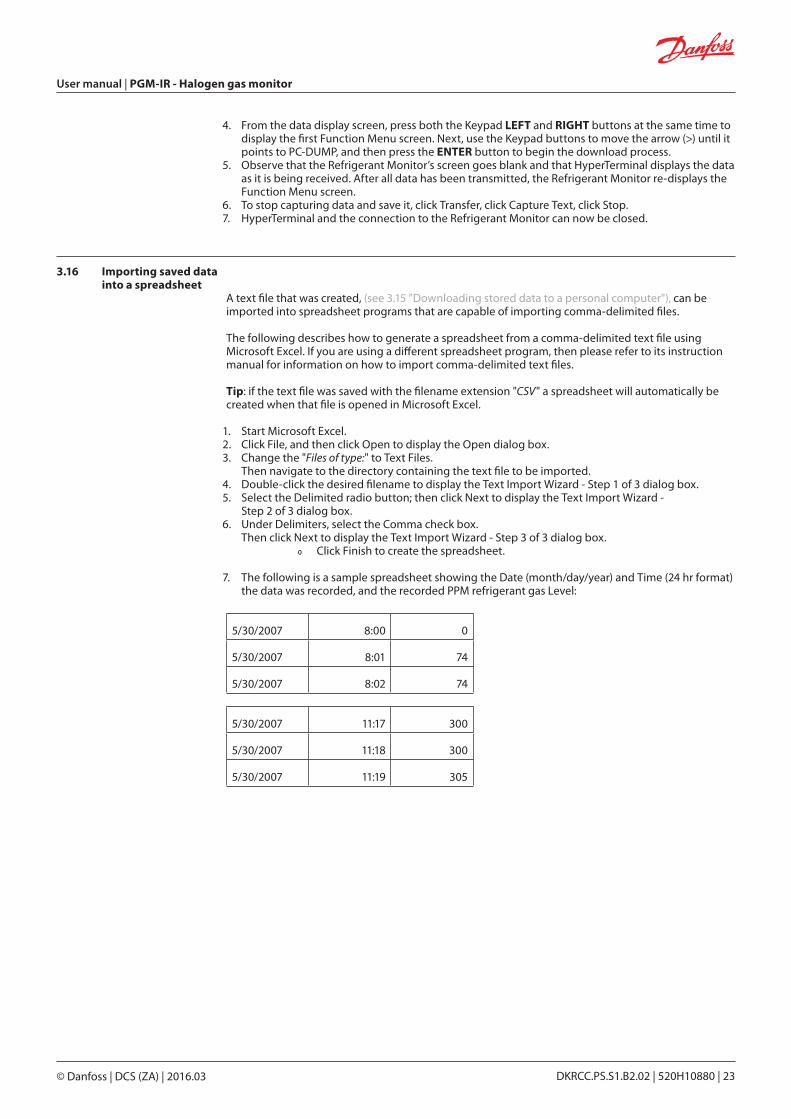
7. The following is a sample spreadsheet showing the Date (month/day/year) and Time (24 hr format) the data was recorded, and the recorded PPM refrigerant gas Level:
5/30/2007 8:00 0
5/30/2007 8:01 74
5/30/2007 8:02 74
5/30/2007 11:17 300
5/30/2007 11:18 300
5/30/2007 11:19 305
User manual | PGM-IR - Halogen gas monitor
© Danfoss | DCS (ZA) | 2016.03 DKRCC.PS.S1.B2.02 | 520H10880 | 23
4.0 Maintenance
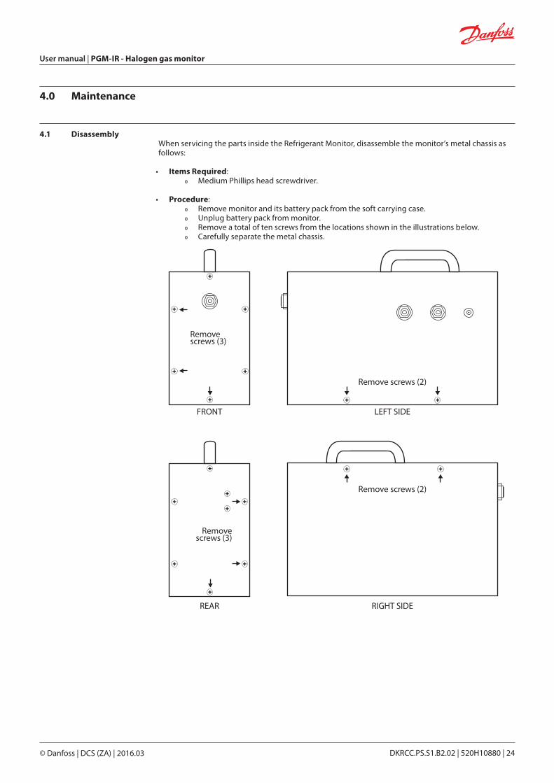
4.1 DisassemblyWhen servicing the parts inside the Refrigerant Monitor, disassemble the monitor’s metal chassis as follows:
• Items Required: Ř Medium Phillips head screwdriver.
• Procedure: Ř Remove monitor and its battery pack from the soft carrying case. Ř Unplug battery pack from monitor. Ř Remove a total of ten screws from the locations shown in the illustrations below. Ř Carefully separate the metal chassis.
Removescrews (3)
Remove screws (2)
Remove screws (2)
Removescrews (3)
FRONT LEFT SIDE
REAR RIGHT SIDE
User manual | PGM-IR - Halogen gas monitor
© Danfoss | DCS (ZA) | 2016.03 DKRCC.PS.S1.B2.02 | 520H10880 | 24
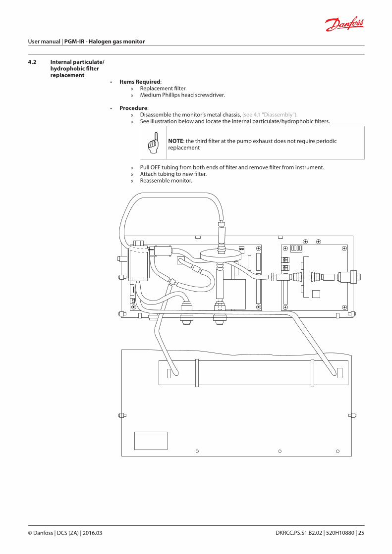
4.2 Internal particulate/ hydrophobic filter replacement
• Items Required: Ř Replacement filter. Ř Medium Phillips head screwdriver.
• Procedure: Ř Disassemble the monitor’s metal chassis, (see 4.1 "Diassembly"). Ř See illustration below and locate the internal particulate/hydrophobic filters.
NOTE: the third filter at the pump exhaust does not require periodic replacement
Ř Pull OFF tubing from both ends of filter and remove filter from instrument. Ř Attach tubing to new filter. Ř Reassemble monitor.
User manual | PGM-IR - Halogen gas monitor
© Danfoss | DCS (ZA) | 2016.03 DKRCC.PS.S1.B2.02 | 520H10880 | 25
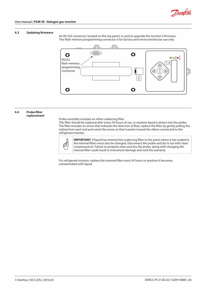
4.3 Updating firmwareAn RS-232 connector, located on the top panel, is used to upgrade the monitor’s firmware. This flash memory programming connector is for factory and service technician use only.
RS232�ash memoryprogrammingconnector
ENTER
ESC
SILENCE
ALA
RM
FAULT
ON
I/O
4.4 Probe filter replacement
Probe assembly includes an inline coalescing filter. This filter should be replaced after every 50 hours of use, or anytime liquid is drawn into the probe.The filter includes an arrow that indicates the direction of flow, replace the filter by gently pulling the tubing from each end and orient the arrow so that it points toward the elbow connected to the refrigerant monitor.
IMPORTANT: if liquid has entered the coalescing filter to the point where it has soaked it, the internal filters must also be changed. Disconnect the probe and dry it out with clean compressed air. Failure to properly clean and dry the probe, along with changing the internal filter could result in instrument damage and void the warranty
For refrigerant monitor, replace the external filter every 50 hours or anytime it becomes contaminated with liquid.
User manual | PGM-IR - Halogen gas monitor
© Danfoss | DCS (ZA) | 2016.03 DKRCC.PS.S1.B2.02 | 520H10880 | 26
5.0 Parts and service
5.1 Replacement parts & optional accessories
Replacement Parts
Part Number Item Description
080Z2148 PAGM FOR COM/MODEL 3015-8002
080Z2149 PAGM FOR HALOCARBON/MODEL 3015-8003
Optional Accessories
Part Number Item Description
080Z2198 Hydrophobic Filter
080Z2199 Line End Dust Filter
C01703200 250 Foot Roll of Tubing (sold per roll)
C01680417 Charcoal Filter
C01680421 HGM Line End Filter
* Installation kit
* Management kit
* The part number changes according to the region, please contact you local Danfoss office.
User manual | PGM-IR - Halogen gas monitor
© Danfoss | DCS (ZA) | 2016.03 DKRCC.PS.S1.B2.02 | 520H10880 | 27
Please contact your local Danfoss office for further information
Danfoss can accept no responsibility for possible errors in catalogues, brochures and other printed material. Danfoss reserves the right to alter its products without notice. This also applies to products already on order provided that such alterations can be made without subsequential changes being necessary eady agreed.All trademarks in this material are property of the respective companies. Danfoss and the Danfoss logotype are trademarks of Danfoss A/S. All rights reserved.
© Danfoss | DCS (ZA) | 2016.03 DKRCC.PS.S1.B2.02 | 520H10880 | 28