Embed Size (px)
Citation preview
Version 004.01
OperatiOn Manual
Digital Gas Dector/Controller
taBle OF COntentS
1.0 General Description 1.1 Applications 1.2 Features 1.3 Outputs 1.4 User Interface
2.0 Model Selection Guide
3.0 Installation 3.1 Wiring 3.2 Installation Guide 3.3 Sensor Placement
4.0 Operation 4.1 Screen Display 4.2 Default Settings 4.3 Changing Settings 4.4 List of Settings
5.0 CAN Network Configuration 5.1 Using CAN Network, Central Controller 5.2 Using CAN Network No Central Controller 5.3 Defaults Configuration 5.4 Addresses 5.5 Creating Zones or Groups 5.6 Output Relays
6.0 Maintenance Guide 6.1 Quick Test Caution 6.2 Calibration Procedure
7.0 BACnet Network Configuration 7.1 Ventilation Controlled by BACnet Building Automation System 7.2 Ventilation Controlled directly by Gas Sensors
6000 Series Digital Gas Detector/Controller
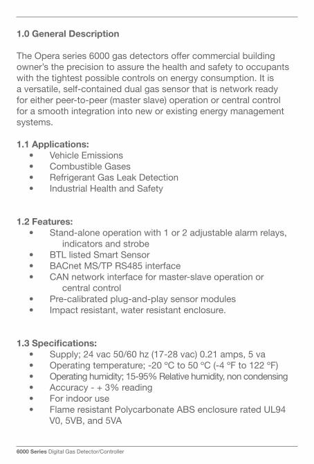
1.0 General Description
The Opera series 6000 gas detectors offer commercial building owner’s the precision to assure the health and safety to occupants with the tightest possible controls on energy consumption. It is a versatile, self-contained dual gas sensor that is network ready for either peer-to-peer (master slave) operation or central control for a smooth integration into new or existing energy management systems.
1.1 applications:• VehicleEmissions• CombustibleGases• RefrigerantGasLeakDetection• IndustrialHealthandSafety
1.2 Features:• Stand-aloneoperationwith1or2adjustablealarmrelays, indicators and strobe• BTLlistedSmartSensor• BACnetMS/TPRS485interface• CANnetworkinterfaceformaster-slaveoperationor central control• Pre-calibratedplug-and-playsensormodules• Impactresistant,waterresistantenclosure.
1.3 Specifications:• Supply;24vac50/60hz(17-28vac)0.21amps,5va• Operatingtemperature;-20ºCto50ºC(-4ºFto122ºF)• Operatinghumidity;15-95%Relativehumidity,noncondensing• Accuracy-+3%reading• Forindooruse• FlameresistantPolycarbonateABSenclosureratedUL94 V0, 5VB, and 5VA
1.0 General Description
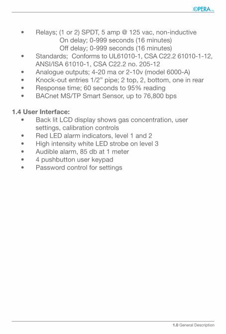
• Relays;(1or2)SPDT,5amp@125vac,non-inductive Ondelay;0-999seconds(16minutes) Offdelay;0-999seconds(16minutes)• Standards;ConformstoUL61010-1,CSAC22.261010-1-12, ANSI/ISA 61010-1, CSA C22.2 no. 205-12• Analogueoutputs;4-20maor2-10v(model6000-A)• Knock-outentries1/2”pipe;2top,2,bottom,oneinrear• Responsetime;60secondsto95%reading• BACnetMS/TPSmartSensor,upto76,800bps
1.4 user interface:• BacklitLCDdisplayshowsgasconcentration,user settings, calibration controls• RedLEDalarmindicators,level1and2• HighintensitywhiteLEDstrobeonlevel3• Audiblealarm,85dbat1meter• 4pushbuttonuserkeypad• Passwordcontrolforsettings
6000 Series Digital Gas Detector/Controller
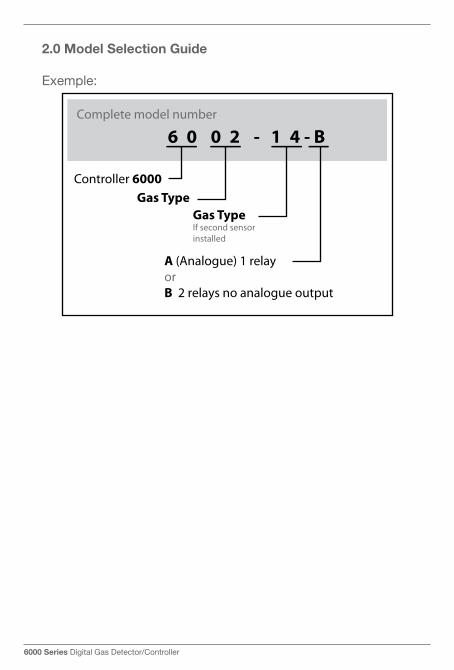
2.0 Model Selection Guide
Exemple:
2.0 Model Selection Guide
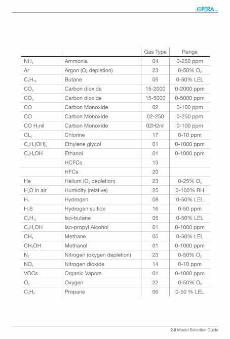
Gas Type Range
NH3 Ammonia 04 0-250 ppm
Ar Argon (O2 depletion) 23 0-50%O2
C4H10 Butane 05 0-50%LEL
CO2 Carbon dioxide 15-2000 0-2000 ppm
CO2 Carbon dioxide 15-5000 0-5000 ppm
CO Carbon Monoxide 02 0-100 ppm
CO Carbon Monoxide 02-250 0-250 ppm
COH2nil Carbon Monoxide 02H2nil 0-100 ppm
CL2 Chlorine 17 0-10 ppm
C2H4(OH)2 Ethyleneglycol 01 0-1000 ppm
C2H5OH Ethanol 01 0-1000 ppm
HCFCs 13
HFCs 20
He Helium(O2 depletion) 23 0-25%O2
H2O in air Humidity(relative) 25 0-100%RH
H2 Hydrogen 08 0-50%LEL
H2S Hydrogensulfide 16 0-50 ppm
C4H10 Iso-butane 05 0-50%LEL
C3H7OH Iso-propyl Alcohol 01 0-1000 ppm
CH4 Methane 05 0-50%LEL
CH3OH Methanol 01 0-1000 ppm
N2 Nitrogen (oxygen depletion) 23 0-50%O2
NO2 Nitrogen dioxide 14 0-10 ppm
VOCs Organic Vapors 01 0-1000 ppm
O2 Oxygen 22 0-50%O2
C3H8 Propane 06 0-50%LEL
6000 Series Digital Gas Detector/Controller
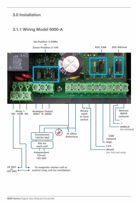
3.0 installation
3.1.1 Wiring Model 6000-a
24 VACor
120 VAC
IndependantCircuit
120 VAC
To magnetic starter coil orcontrol relay coil for ventilation
Transformer120/24 VAC
To OtherDetectors
BACnet MSTP
network
CANnetwork
Binary input
to limit switch
EOL CAN
Up Position 4-20Maor
Down Position 2-10V EOL BACnet
5Va foreach unit
NO COMRelay 1
NC ANA1 GAnalogue Output
ANA2
–
+
SHIELD(no connect)
High
Low
Shield(on 1rst unit only)
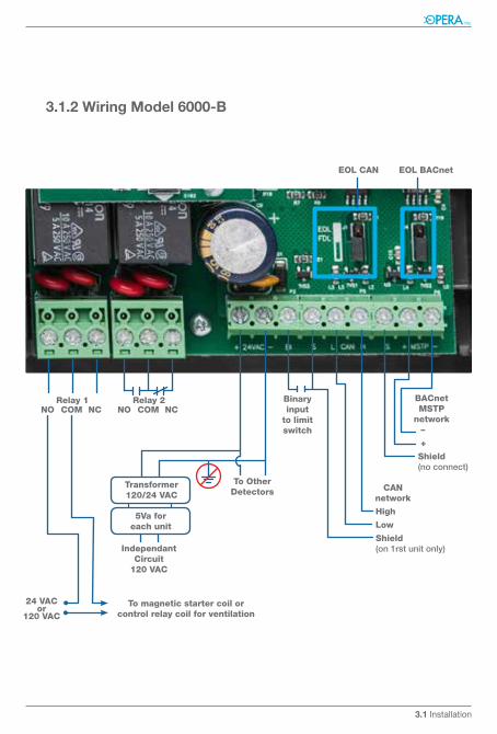
3.1.2 Wiring Model 6000-B
24 VACor
120 VAC
Independant Circuit
120 VAC
To magnetic starter coil orcontrol relay coil for ventilation
Transformer120/24 VAC
To OtherDetectors
BACnetMSTP
network
CANnetwork
Binary input
to limit switch
EOL CAN EOL BACnet
5Va foreach unit
NO COMRelay 1
NC NO COMRelay 2
NC
3.1 Installation
–
+
SHIELD(no connect)
–
+
Shield(no connect)
High
Low
Shield(on 1rst unit only)
6000 Series Digital Gas Detector/Controller
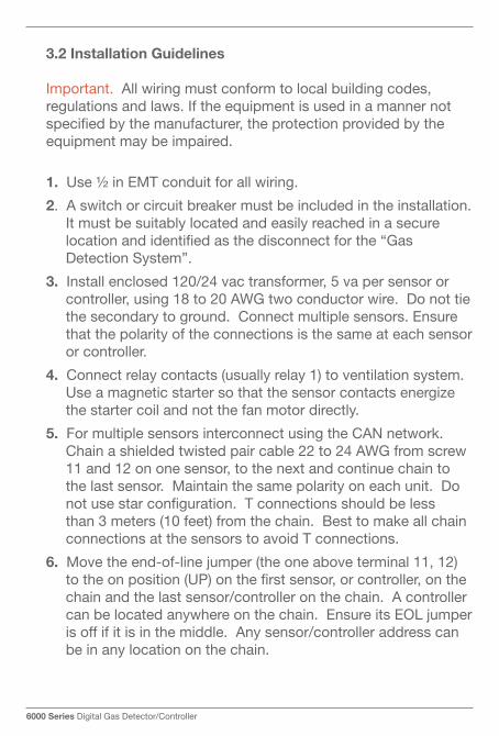
3.2 installation Guidelines
Important. All wiring must conform to local building codes, regulations and laws. If the equipment is used in a manner not specified by the manufacturer, the protection provided by the equipment may be impaired.
1. Use½inEMTconduitforallwiring.
2. A switch or circuit breaker must be included in the installation. It must be suitably located and easily reached in a secure location and identified as the disconnect for the “Gas DetectionSystem”.
3. Install enclosed 120/24 vac transformer, 5 va per sensor or controller,using18to20AWGtwoconductorwire.Donottiethesecondarytoground.Connectmultiplesensors.Ensurethat the polarity of the connections is the same at each sensor or controller.
4. Connect relay contacts (usually relay 1) to ventilation system. Useamagneticstartersothatthesensorcontactsenergizethe starter coil and not the fan motor directly.
5. For multiple sensors interconnect using the CAN network. Chain a shielded twisted pair cable 22 to 24 AWG from screw 11 and 12 on one sensor, to the next and continue chain to the last sensor. Maintain the same polarity on each unit. Do not use star configuration. T connections should be less than 3 meters (10 feet) from the chain. Best to make all chain connections at the sensors to avoid T connections.
6. Movetheend-of-linejumper(theoneaboveterminal11,12)to the on position (UP) on the first sensor, or controller, on the chain and the last sensor/controller on the chain. A controller canbelocatedanywhereonthechain.EnsureitsEOLjumperis off if it is in the middle. Any sensor/controller address can be in any location on the chain.
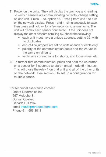
7. Power on the units. They will display the gas type and reading. To verify if sensors are communicating correctly, change setting on one unit. Press → to, option 56. Press ↑ from 0 to 1 to turn on the network display. Press ↑ and ← simultaneously to save, then press and hold ← for a few seconds to return home. The unit will display each sensor connected. If the unit does not displaytheothersensorsscrollingby,checkthefollowing;
•eachunitmusthaveauniqueaddress,setting39,with no duplicates•end-of-linejumpersaresetonunitsatendsofcableonly•polarityofthecommunicationcableandthe24vacis the same on all units•verifywireconnectionsforshorts,andloosewires,etc.
8. To further test communication, press and hold the up button on a sensor for 5 seconds to start manual mode (5 minutes). This will close the relay 1 on that unit and all of the other units on the network. See section 5 to set up a configuration for multiplezones.
Fortechnicalassistancecontact;OperaElectronicsInc.697MelocheStDorval, QuebecCanadaH9P2S4email [email protected] 514 556 3013
3.2 Installation
6000 Series Digital Gas Detector/Controller
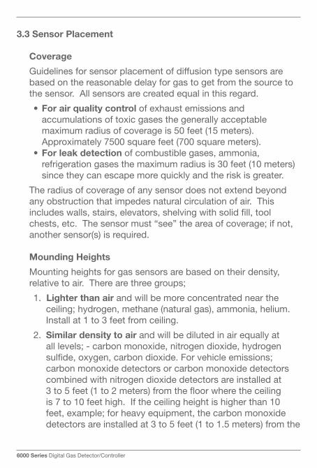
3.3 Sensor placement
Coverage
Guidelines for sensor placement of diffusion type sensors are based on the reasonable delay for gas to get from the source to the sensor. All sensors are created equal in this regard.
•For air quality control of exhaust emissions and accumulations of toxic gases the generally acceptable maximum radius of coverage is 50 feet (15 meters). Approximately 7500 square feet (700 square meters).
•For leak detection of combustible gases, ammonia, refrigeration gases the maximum radius is 30 feet (10 meters) since they can escape more quickly and the risk is greater.
The radius of coverage of any sensor does not extend beyond any obstruction that impedes natural circulation of air. This includes walls, stairs, elevators, shelving with solid fill, tool chests,etc.Thesensormust“see”theareaofcoverage;ifnot,another sensor(s) is required. Mounding Heights
Mounting heights for gas sensors are based on their density, relativetoair.Therearethreegroups;
1. lighter than air and will be more concentrated near the ceiling;hydrogen,methane(naturalgas),ammonia,helium.Install at 1 to 3 feet from ceiling.
2. Similar density to air and will be diluted in air equally at alllevels;-carbonmonoxide,nitrogendioxide,hydrogensulfide,oxygen,carbondioxide.Forvehicleemissions;carbon monoxide detectors or carbon monoxide detectors combined with nitrogen dioxide detectors are installed at 3 to 5 feet (1 to 2 meters) from the floor where the ceiling is 7 to 10 feet high. If the ceiling height is higher than 10 feet,example;forheavyequipment,thecarbonmonoxidedetectors are installed at 3 to 5 feet (1 to 1.5 meters) from the

floor as per the requirements of the building code regulations and the nitrogen dioxide detectors should be installed at 50%oftheceilingheightandabovethevehicleheighttobe in the open circulation of the air. If the exhaust pipes of diesel vehicles are below the vehicles, then the nitrogen dioxide detectors should be installed at 3 to 5 feet (1 to 1.5 meters) from the floor. Other gases in this group are typically installed at 3 to 5 feet (1 to 1.5 meters) from floor but can beinstalledupto50%oftheceilingheight.Inallcasesthedetectors must be installed above obstructions blocking circulationofairinfrontofthedetectors,forexample;maintenance areas in automobile dealerships where tool chests, work tables and storage racks typically line all walls require the installation of sensors at 6 to 10 feet (2 to 6 meters) off floor to be in the free flow air circulation.
3. Heavier than airandwillconcentratenearthefloor;-HFCs,HCFCs,propane,chlorine,mostorganicvapors(consultOpera), butane. Install sensors at 1-3 feet from floor.
For all types of sensors avoid drafts, obstacles, aerosols, silicones. Place sensors in the center of its coverage area as much as possible.
3.3 Installation
6000 Series Digital Gas Detector/Controller
4.0 OperatiOn
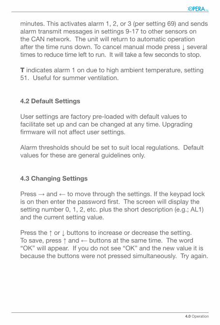
4.1 Screen Display
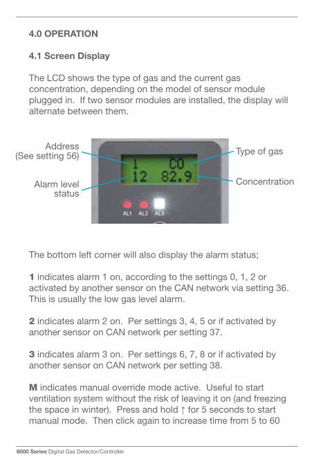
The LCD shows the type of gas and the current gas concentration, depending on the model of sensor module plugged in. If two sensor modules are installed, the display will alternate between them.
Thebottomleftcornerwillalsodisplaythealarmstatus;
1 indicates alarm 1 on, according to the settings 0, 1, 2 or activated by another sensor on the CAN network via setting 36. This is usually the low gas level alarm.
2 indicates alarm 2 on. Per settings 3, 4, 5 or if activated by another sensor on CAN network per setting 37.
3indicatesalarm3on.Persettings6,7,8orifactivatedbyanothersensoronCANnetworkpersetting38.
M indicates manual override mode active. Useful to start ventilationsystemwithouttheriskofleavingiton(andfreezingthe space in winter). Press and hold ↑ for 5 seconds to start manual mode. Then click again to increase time from 5 to 60
Address (See setting 56)
Alarm level status
Type of gas
Concentration
minutes.Thisactivatesalarm1,2,or3(persetting69)andsendsalarmtransmitmessagesinsettings9-17toothersensorsonthe CAN network. The unit will return to automatic operation after the time runs down. To cancel manual mode press ↓ several times to reduce time left to run. It will take a few seconds to stop.
T indicates alarm 1 on due to high ambient temperature, setting 51. Useful for summer ventilation.
4.2 Default Settings
User settings are factory pre-loaded with default values to facilitate set up and can be changed at any time. Upgrading firmware will not affect user settings.
Alarm thresholds should be set to suit local regulations. Default values for these are general guidelines only.
4.3 Changing Settings
Press → and ← to move through the settings. If the keypad lock is on then enter the password first. The screen will display the settingnumber0,1,2,etc.plustheshortdescription(e.g.;AL1)and the current setting value.
Press the ↑ or ↓ buttons to increase or decrease the setting.To save, press ↑ and ← buttons at the same time. The word “OK”willappear.Ifyoudonotsee“OK”andthenewvalueitisbecause the buttons were not pressed simultaneously. Try again.
4.0 Operation
Type of gas
Concentration
6000 Series Digital Gas Detector/Controller
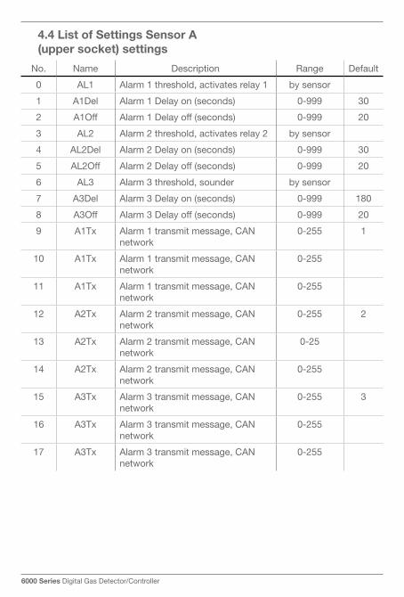
No. Name Description Range Default
0 AL1 Alarm 1 threshold, activates relay 1 by sensor
1 A1Del Alarm 1 Delay on (seconds) 0-999 30
2 A1Off Alarm 1 Delay off (seconds) 0-999 20
3 AL2 Alarm 2 threshold, activates relay 2 by sensor
4 AL2Del Alarm 2 Delay on (seconds) 0-999 30
5 AL2Off Alarm 2 Delay off (seconds) 0-999 20
6 AL3 Alarm 3 threshold, sounder by sensor
7 A3Del Alarm 3 Delay on (seconds) 0-999 180
8 A3Off Alarm 3 Delay off (seconds) 0-999 20
9 A1Tx Alarm 1 transmit message, CAN network
0-255 1
10 A1Tx Alarm 1 transmit message, CAN network
0-255
11 A1Tx Alarm 1 transmit message, CAN network
0-255
12 A2Tx Alarm 2 transmit message, CAN network
0-255 2
13 A2Tx Alarm 2 transmit message, CAN network
0-25
14 A2Tx Alarm 2 transmit message, CAN network
0-255
15 A3Tx Alarm 3 transmit message, CAN network
0-255 3
16 A3Tx Alarm 3 transmit message, CAN network
0-255
17 A3Tx Alarm 3 transmit message, CAN network
0-255
4.4 list of Settings Sensor a (upper socket) settings
No. Name Description Range Default
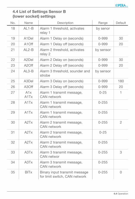
18 AL1-B Alarm 1 threshold, activates relay 1
by senor
19 A1Del Alarm 1 Delay on (seconds) 0-999 30
20 A1Off Alarm 1 Delay off (seconds) 0-999 20
21 AL2-B Alarm 2 threshold, activates relay 2
by sensor
22 A2Del Alarm 2 Delay on (seconds) 0-999 30
23 A2Off Alarm 2 Delay off (seconds) 0-999 20
24 AL3-B Alarm 3 threshold, sounder and strobe
by sensor
25 A3Del Alarm 3 Delay on (seconds) 0-999 180
26 A3Off Alarm 3 Delay off (seconds) 0-999 20
27 A1xA1Tx
Alarm 1 transmit message, CAN network
0-25 1
28 A1Tx Alarm 1 transmit message, CAN network
0-255
29 A1Tx Alarm 1 transmit message, CAN network
0-255
30 A2Tx Alarm 2 transmit message, CAN network
0-255 2
31 A2Tx Alarm 2 transmit message, CAN network
0-25
32 A2Tx Alarm 2 transmit message, CAN network
0-255
33 A3Tx Alarm 3 transmit message, CAN networ
0-255 3
34 A3Tx Alarm 3 transmit message, CAN network
0-255
35 BITx Binary input transmit message for limit switch, CAN network
0-255 0
4.4 list of Settings Sensor B (lower socket) settings
4.4 Operation
6000 Series Digital Gas Detector/Controller
No. Name Description Range Default
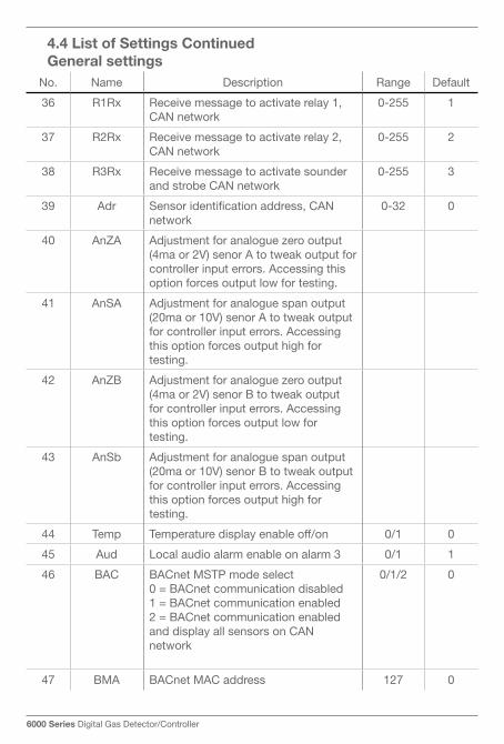
36 R1Rx Receive message to activate relay 1, CAN network
0-255 1
37 R2Rx Receive message to activate relay 2, CAN network
0-255 2
38 R3Rx Receive message to activate sounder and strobe CAN network
0-255 3
39 Adr Sensor identification address, CAN network
0-32 0
40 AnZA Adjustmentforanaloguezerooutput(4ma or 2V) senor A to tweak output for controller input errors. Accessing this option forces output low for testing.
41 AnSA Adjustmentforanaloguespanoutput(20ma or 10V) senor A to tweak output for controller input errors. Accessing this option forces output high for testing.
42 AnZB Adjustmentforanaloguezerooutput(4ma or 2V) senor B to tweak output for controller input errors. Accessing this option forces output low for testing.
43 AnSb Adjustmentforanaloguespanoutput(20ma or 10V) senor B to tweak output for controller input errors. Accessing this option forces output high for testing.
44 Temp Temperature display enable off/on 0/1 0
45 Aud Local audio alarm enable on alarm 3 0/1 1
46 BAC BACnet MSTP mode select0 = BACnet communication disabled1 = BACnet communication enabled2 = BACnet communication enabled and display all sensors on CAN network
0/1/2 0
47 BMA BACnet MAC address 127 0
4.4 list of Settings Continued General settings
No. Name Description Range Default
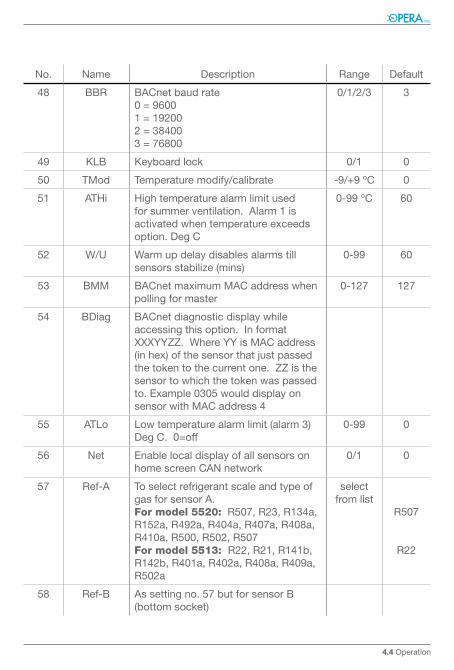
48 BBR BACnet baud rate0=96001=192002=384003=76800
0/1/2/3 3
49 KLB Keyboardlock 0/1 0
50 TMod Temperature modify/calibrate -9/+9ºC 0
51 ATHi Hightemperaturealarmlimitusedfor summer ventilation. Alarm 1 is activated when temperature exceeds option. Deg C
0-99ºC 60
52 W/U Warm up delay disables alarms till sensorsstabilize(mins)
0-99 60
53 BMM BACnet maximum MAC address when polling for master
0-127 127
54 BDiag BACnet diagnostic display while accessing this option. In format XXXYYZZ. Where YY is MAC address (inhex)ofthesensorthatjustpassedthe token to the current one. ZZ is the sensor to which the token was passed to.Example0305woulddisplayonsensor with MAC address 4
55 ATLo Low temperature alarm limit (alarm 3) Deg C. 0=off
0-99 0
56 Net Enablelocaldisplayofallsensorsonhome screen CAN network
0/1 0
57 Ref-A To select refrigerant scale and type of gas for sensor A.For model 5520: R507, R23, R134a, R152a,R492a,R404a,R407a,R408a,R410a, R500, R502, R507For model 5513: R22, R21, R141b, R142b,R401a,R402a,R408a,R409a,R502a
select from list
R507
R22
58 Ref-B As setting no. 57 but for sensor B (bottom socket)
4.4 Operation
6000 Series Digital Gas Detector/Controller
No. Name Description Range Default
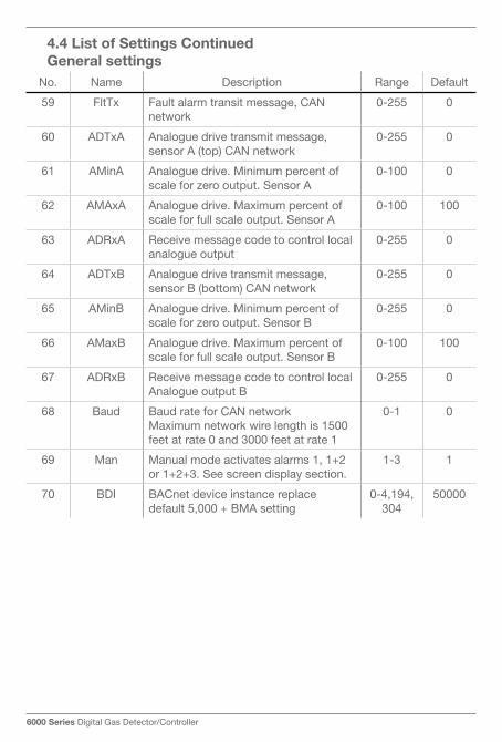
59 FltTx Fault alarm transit message, CAN network
0-255 0
60 ADTxA Analogue drive transmit message, sensor A (top) CAN network
0-255 0
61 AMinA Analogue drive. Minimum percent of scaleforzerooutput.SensorA
0-100 0
62 AMAxA Analogue drive. Maximum percent of scale for full scale output. Sensor A
0-100 100
63 ADRxA Receive message code to control local analogue output
0-255 0
64 ADTxB Analogue drive transmit message, sensor B (bottom) CAN network
0-255 0
65 AMinB Analogue drive. Minimum percent of scaleforzerooutput.SensorB
0-255 0
66 AMaxB Analogue drive. Maximum percent of scale for full scale output. Sensor B
0-100 100
67 ADRxB Receive message code to control local Analogue output B
0-255 0
68 Baud Baud rate for CAN networkMaximum network wire length is 1500 feet at rate 0 and 3000 feet at rate 1
0-1 0
69 Man Manualmodeactivatesalarms1,1+2or1+2+3.Seescreendisplaysection.
1-3 1
70 BDI BACnet device instance replace default5,000+BMAsetting
0-4,194,304
50000
4.4 list of Settings Continued General settings
4.4 Operation
5.0 network Configuration
5.1 using Can network with a Central Controller
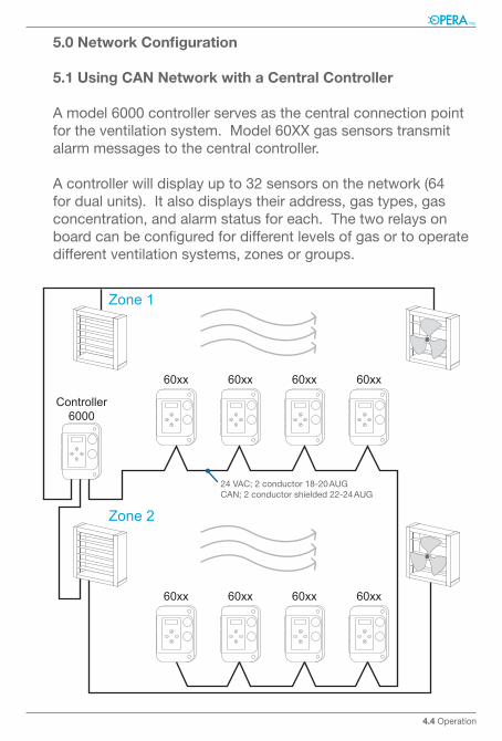
A model 6000 controller serves as the central connection point for the ventilation system. Model 60XX gas sensors transmit alarm messages to the central controller.
A controller will display up to 32 sensors on the network (64 for dual units). It also displays their address, gas types, gas concentration, and alarm status for each. The two relays on board can be configured for different levels of gas or to operate differentventilationsystems,zonesorgroups.
60xx 60xx 60xx 60xx
60xx 60xx 60xx 60xx
Controller6000
Zone 1
Zone 2
24VAC;2conductor18-20AUGCAN;2conductorshielded22-24AUG
6000 Series Digital Gas Detector/Controller
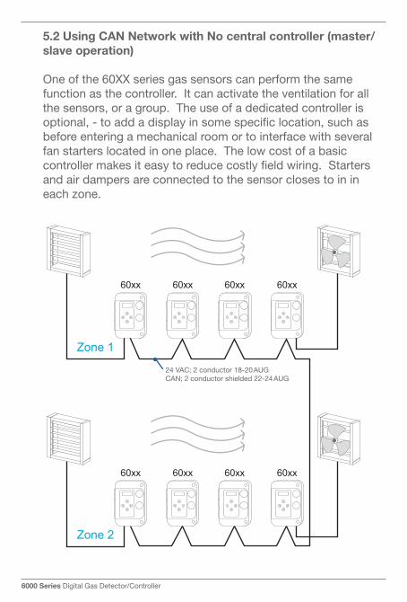
5.2 using Can network with no central controller (master/slave operation)
One of the 60XX series gas sensors can perform the same function as the controller. It can activate the ventilation for all the sensors, or a group. The use of a dedicated controller is optional, - to add a display in some specific location, such as before entering a mechanical room or to interface with several fan starters located in one place. The low cost of a basic controller makes it easy to reduce costly field wiring. Starters and air dampers are connected to the sensor closes to in in eachzone.
60xx 60xx 60xx 60xx
60xx 60xx 60xx 60xx
Zone 1
Zone 2
24VAC;2conductor18-20AUGCAN;2conductorshielded22-24AUG
5.0 network Configuration
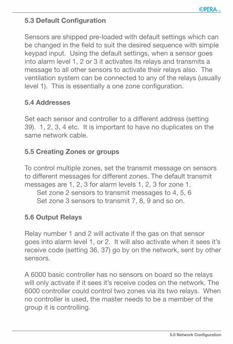
5.3 Default Configuration
Sensors are shipped pre-loaded with default settings which can be changed in the field to suit the desired sequence with simple keypad input. Using the default settings, when a sensor goes into alarm level 1, 2 or 3 it activates its relays and transmits a message to all other sensors to activate their relays also. The ventilation system can be connected to any of the relays (usually level1).Thisisessentiallyaonezoneconfiguration.
5.4 addresses
Set each sensor and controller to a different address (setting 39).1,2,3,4etc.Itisimportanttohavenoduplicatesonthesame network cable.
5.5 Creating Zones or groups
Tocontrolmultiplezones,setthetransmitmessageonsensorstodifferentmessagesfordifferentzones.Thedefaulttransmitmessagesare1,2,3foralarmlevels1,2,3forzone1. Setzone2sensorstotransmitmessagesto4,5,6 Setzone3sensorstotransmit7,8,9andsoon.
5.6 Output relays
Relay number 1 and 2 will activate if the gas on that sensor goes into alarm level 1, or 2. It will also activate when it sees it’s receive code (setting 36, 37) go by on the network, sent by other sensors.
A 6000 basic controller has no sensors on board so the relays will only activate if it sees it’s receive codes on the network. The 6000controllercouldcontroltwozonesviaitstworelays.Whenno controller is used, the master needs to be a member of the group it is controlling.
6000 Series Digital Gas Detector/Controller
6.0 Maintenance Guide
All sensors are shipped from the factory pre-calibrated. To maintain accuracy and conformity with standards it is essential that they be calibrated by a qualified technician at least once per year using certified bottled gas mixtures.
6.1 Quick test Caution
Operadoesnotapprovetheuseofthesocalled“bumptest”.This where a gas of a higher concentration than the alarm level issimplyinjectedintothesensortocausethealarmtotrigger.The gas in these bottles is a higher concentration than what is used for proper calibration. This only test the operation of the alarm with no regard for the intended alarm settings, similar to simply pressing a test button.
Usecertifiedprecisionmixturestoadjustthesensitivityofthesensor due to normal wear and aging and guarantee that the designed alarm set points are respected. It will also indicate the general condition of a sensor that is due for replacement. So called“automaticcalibration”or“self-test”willnotprovidethislevel of security.
6.2 Calibration procedure
1.Usecertifiedbottledcalibrationgasmixturesonly.Ensure
that sensors are powered on for a minimum of the break-in
period for the sensor. For electro-chemical sensors this is
only a few minutes.
2. Press the right arrow to enter settings
3. Press the ↑ and → at the same time to enter calibration
mode.SAZ(sensorAzero)willdisplayandthecurrentgas
reading on the top line
6.0 Maintenance Guide
4. Injectbottledzerogasintofirstsensor.Useaflowrateof
0.1 LPM to 2 LPM. The gas fitting to sensor should not be
sealed tight. If it is the pressure will increase and distort the
reading (high).
5. Adjustgasreadingtozerowiththe↑ and ↓ buttons
6. Press ↑ and ← at the same time to save
7. Press → The display will show SAS (sensor A span) and the
current gas reading
8. Injectbottledspangasintofirstsensorandwaituntilthegas
reading stops going up. The span gas should must be within
the range of sensor’s scale.
9. Adjustthereadingtomatchtheconcentrationinthebottle
10. Press ↑ and ← at the same time to save
11. If second sensor installed press → and repeat steps 3 to 10
for sensor B
12. Press left arrow several times to return to settings.
6000 Series Digital Gas Detector/Controller
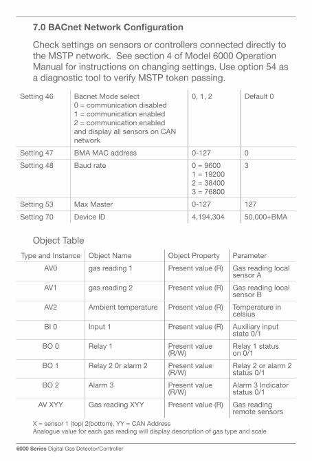
7.0 BaCnet network Configuration
Check settings on sensors or controllers connected directly to the MSTP network. See section 4 of Model 6000 Operation Manual for instructions on changing settings. Use option 54 as a diagnostic tool to verify MSTP token passing.
ObjectTable
Setting 46 Bacnet Mode select0 = communication disabled1 = communication enabled2 = communication enabled and display all sensors on CAN network
0, 1, 2 Default 0
Setting 47 BMA MAC address 0-127 0
Setting48 Baud rate 0=96001=192002=384003=76800
3
Setting 53 Max Master 0-127 127
Setting 70 Device ID 4,194,304 50,000+BMA
X = sensor 1 (top) 2(bottom), YY = CAN AddressAnalogue value for each gas reading will display description of gas type and scale
Type and Instance ObjectName ObjectProperty Parameter
AV0 gas reading 1 Present value (R) Gas reading local sensor A
AV1 gas reading 2 Present value (R) Gas reading local sensor B
AV2 Ambient temperature Present value (R) Temperature in celsius
BI 0 Input 1 Present value (R) Auxiliary input state 0/1
BO 0 Relay 1 Present value (R/W)
Relay 1 status on 0/1
BO 1 Relay 2 0r alarm 2 Present value (R/W)
Relay 2 or alarm 2 status 0/1
BO 2 Alarm 3 Present value (R/W)
Alarm 3 Indicator status 0/1
AV XYY Gas reading XYY Present value (R) Gas reading remote sensors
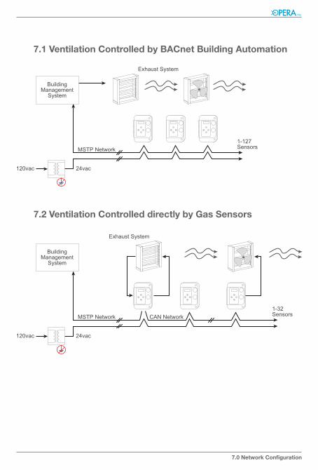
7.1 Ventilation Controlled by BaCnet Building automation
7.2 Ventilation Controlled directly by Gas Sensors
7.0 network Configuration