Embed Size (px)
Citation preview
Personal Hydrogen Sulfide Gas Monitor
HS-03 Operating Manual
PT0E-1302
Safety information
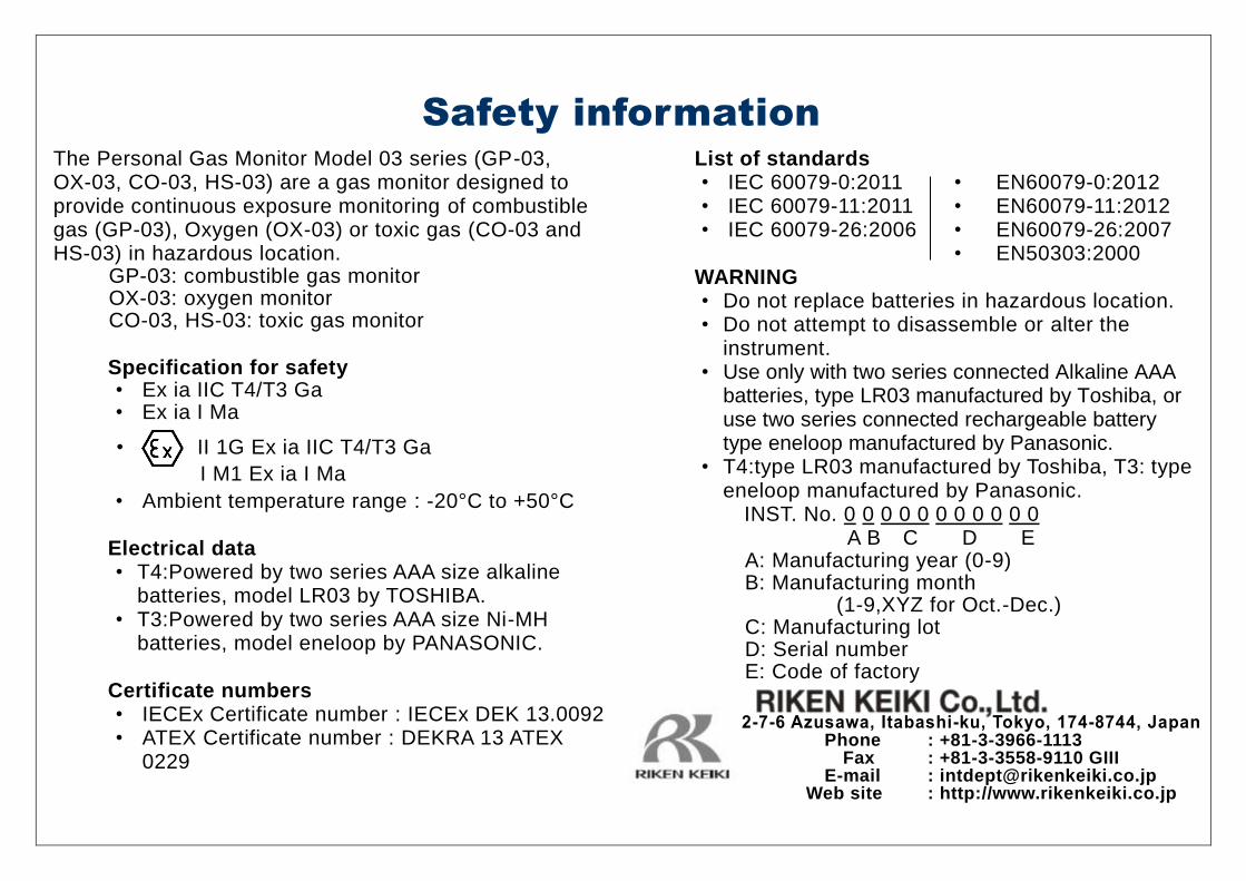
The Personal Gas Monitor Model 03 series (GP-03, OX-03, CO-03, HS-03) are a gas monitor designed to provide continuous exposure monitoring of combustible gas (GP-03), Oxygen (OX-03) or toxic gas (CO-03 and HS-03) in hazardous location.
GP-03: combustible gas monitor OX-03: oxygen monitor CO-03, HS-03: toxic gas monitor
Specification for safety • Ex ia IIC T4/T3 Ga • Ex ia I Ma • Ambient temperature range : -20°C to +50°C
Electrical data • T4:Powered by two series AAA size alkaline
batteries, model LR03 by TOSHIBA. • T3:Powered by two series AAA size Ni-MH
batteries, model eneloop by PANASONIC.
Certificate numbers • IECEx Certificate number : IECEx DEK 13.0092 • ATEX Certificate number : DEKRA 13 ATEX
0229
List of standards • IEC 60079-0:2011 • EN60079-0:2012 • IEC 60079-11:2011 • EN60079-11:2012 • IEC 60079-26:2006 • EN60079-26:2007
• EN50303:2000 WARNING • Do not replace batteries in hazardous location. • Do not attempt to disassemble or alter the
instrument. • Use only with two series connected Alkaline AAA
batteries, type LR03 manufactured by Toshiba, or use two series connected rechargeable battery type eneloop manufactured by Panasonic.
• T4:type LR03 manufactured by Toshiba, T3: type eneloop manufactured by Panasonic.
INST. No. 0 0 0 0 0 0 0 0 0 0 0 A B C D E
A: Manufacturing year (0-9) B: Manufacturing month
(1-9,XYZ for Oct.-Dec.) C: Manufacturing lot D: Serial number E: Code of factory
• II 1G Ex ia IIC T4/T3 Ga
I M1 Ex ia I Ma
Phone : +81-3-3966-1113 Fax : +81-3-3558-9110 GIII
E-mail : [email protected] Web site : http://www.rikenkeiki.co.jp
1
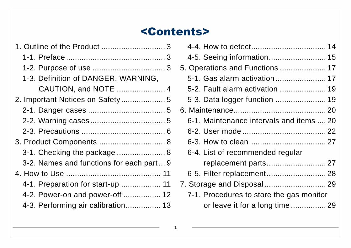
<Contents>
1. Outline of the Product ............................. 3
1-1. Preface ............................................. 3
1-2. Purpose of use ................................. 3
1-3. Definition of DANGER, WARNING,
CAUTION, and NOTE ...................... 4
2. Important Notices on Safety .................... 5
2-1. Danger cases ................................... 5
2-2. Warning cases .................................. 5
2-3. Precautions ...................................... 6
3. Product Components .............................. 8
3-1. Checking the package ...................... 8
3-2. Names and functions for each part ... 9
4. How to Use ........................................... 11
4-1. Preparation for start-up .................. 11
4-2. Power-on and power-off ................. 12
4-3. Performing air calibration................ 13
4-4. How to detect.................................. 14
4-5. Seeing information .......................... 15
5. Operations and Functions ..................... 17
5-1. Gas alarm activation ....................... 17
5-2. Fault alarm activation ..................... 19
5-3. Data logger function ....................... 19
6. Maintenance .......................................... 20
6-1. Maintenance intervals and items .... 20
6-2. User mode ...................................... 22
6-3. How to clean ................................... 27
6-4. List of recommended regular
replacement parts ........................... 27
6-5. Filter replacement ........................... 28
7. Storage and Disposal ............................ 29
7-1. Procedures to store the gas monitor
or leave it for a long time ................ 29
2
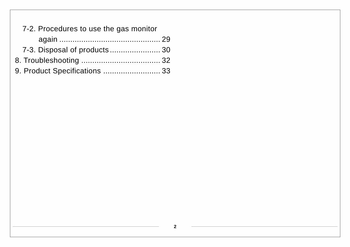
7-2. Procedures to use the gas monitor
again .............................................. 29
7-3. Disposal of products ....................... 30
8. Troubleshooting .................................... 32
9. Product Specifications .......................... 33

3
1
Outline of the Product
1-1. Preface
Thank you for choosing our personal
hydrogen sulfide gas monitor HS-03
(hereinafter referred to as the gas monitor).
Please check that the model number of the
product you purchased is included in the
specifications on this manual.
This manual explains how to use the gas
monitor and its specifications. It contains
information required for using the gas
monitor properly. Not only the first-time users
but also the users who have already used the
product must read and understand the
operating manual to enhance the knowledge
and experience before using the monitor.
1-2. Purpose of use
This product is a single gas monitor used to
detect hydrogen sulfide in the air.
Detection results are not intended to
guarantee life or safety in any way.
4
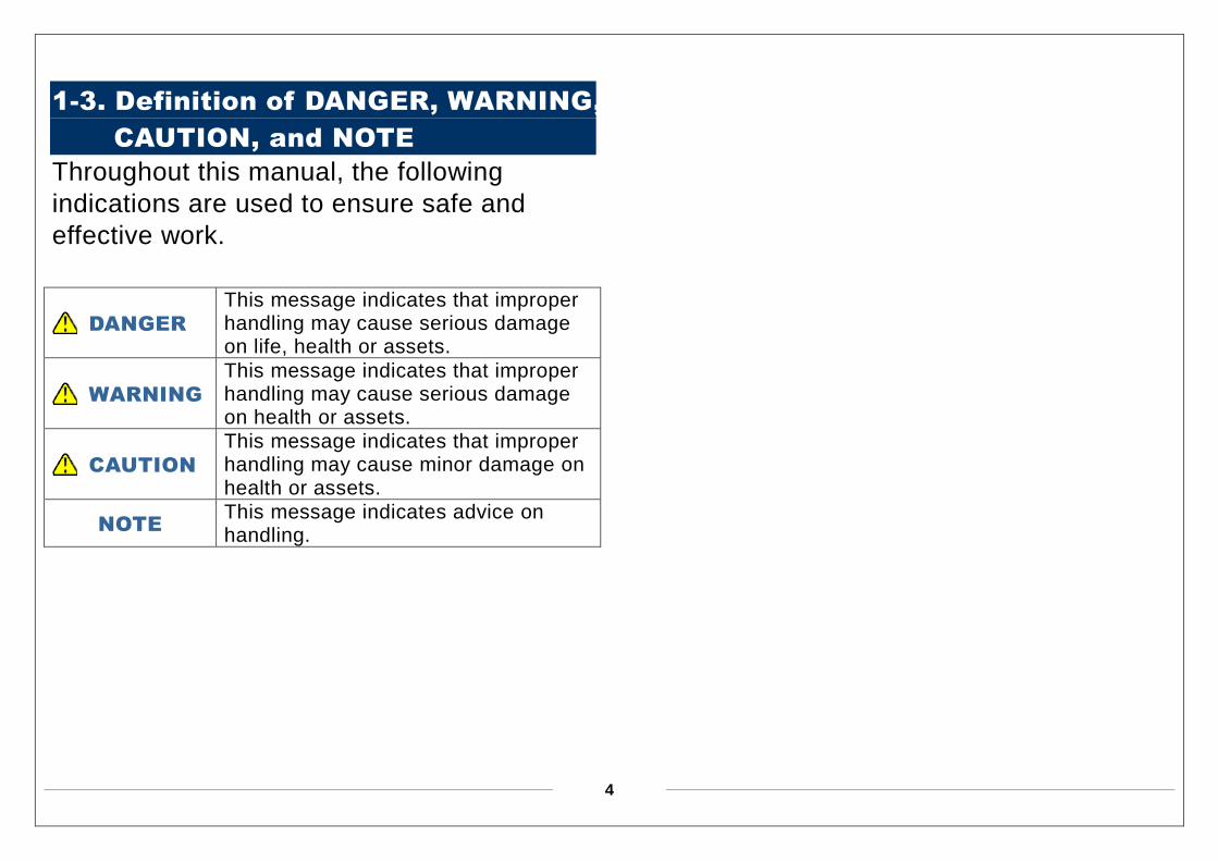
1-3. Definition of DANGER, WARNING,
CAUTION, and NOTE
Throughout this manual, the following
indications are used to ensure safe and
effective work.
DANGER This message indicates that improper handling may cause serious damage on life, health or assets.
WARNING This message indicates that improper handling may cause serious damage on health or assets.
CAUTION This message indicates that improper handling may cause minor damage on health or assets.
NOTE This message indicates advice on handling.
5
2
Important Notices on Safety
2-1. Danger cases
2-2. Warning cases
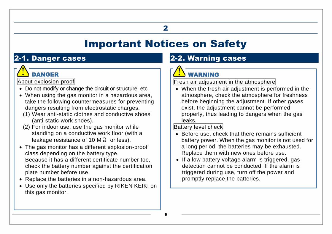
DANGER
About explosion-proof
Do not modify or change the circuit or structure, etc.
When using the gas monitor in a hazardous area, take the following countermeasures for preventing dangers resulting from electrostatic charges.
(1) Wear anti-static clothes and conductive shoes (anti-static work shoes).
(2) For indoor use, use the gas monitor while standing on a conductive work floor (with a
leakage resistance of 10 MΩ or less).
The gas monitor has a different explosion-proof class depending on the battery type. Because it has a different certificate number too, check the battery number against the certification plate number before use.
Replace the batteries in a non-hazardous area.
Use only the batteries specified by RIKEN KEIKI on this gas monitor.
WARNING
Fresh air adjustment in the atmosphere
When the fresh air adjustment is performed in the atmosphere, check the atmosphere for freshness before beginning the adjustment. If other gases exist, the adjustment cannot be performed properly, thus leading to dangers when the gas leaks.
Battery level check
Before use, check that there remains sufficient battery power. When the gas monitor is not used for a long period, the batteries may be exhausted. Replace them with new ones before use.
If a low battery voltage alarm is triggered, gas detection cannot be conducted. If the alarm is triggered during use, turn off the power and promptly replace the batteries.
6
2-3. Precautions
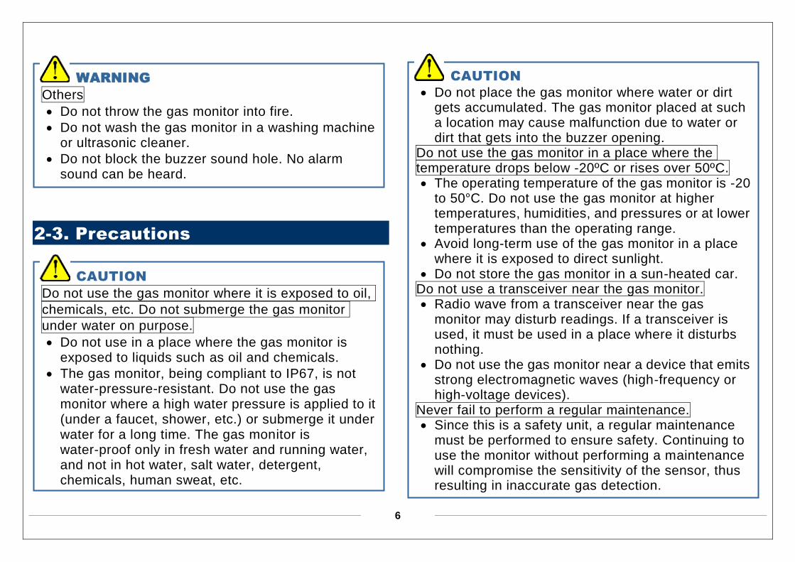
WARNING
Others
Do not throw the gas monitor into fire.
Do not wash the gas monitor in a washing machine or ultrasonic cleaner.
Do not block the buzzer sound hole. No alarm sound can be heard.
CAUTION
Do not use the gas monitor where it is exposed to oil,
chemicals, etc. Do not submerge the gas monitor
under water on purpose.
Do not use in a place where the gas monitor is exposed to liquids such as oil and chemicals.
The gas monitor, being compliant to IP67, is not water-pressure-resistant. Do not use the gas monitor where a high water pressure is applied to it (under a faucet, shower, etc.) or submerge it under water for a long time. The gas monitor is water-proof only in fresh water and running water, and not in hot water, salt water, detergent, chemicals, human sweat, etc.
CAUTION
Do not place the gas monitor where water or dirt gets accumulated. The gas monitor placed at such a location may cause malfunction due to water or dirt that gets into the buzzer opening.
Do not use the gas monitor in a place where the temperature drops below -20ºC or rises over 50ºC. The operating temperature of the gas monitor is -20
to 50ºC. Do not use the gas monitor at higher temperatures, humidities, and pressures or at lower temperatures than the operating range.
Avoid long-term use of the gas monitor in a place where it is exposed to direct sunlight.
Do not store the gas monitor in a sun-heated car. Do not use a transceiver near the gas monitor. Radio wave from a transceiver near the gas
monitor may disturb readings. If a transceiver is used, it must be used in a place where it disturbs nothing.
Do not use the gas monitor near a device that emits strong electromagnetic waves (high-frequency or high-voltage devices).
Never fail to perform a regular maintenance. Since this is a safety unit, a regular maintenance
must be performed to ensure safety. Continuing to use the monitor without performing a maintenance will compromise the sensitivity of the sensor, thus resulting in inaccurate gas detection.
7
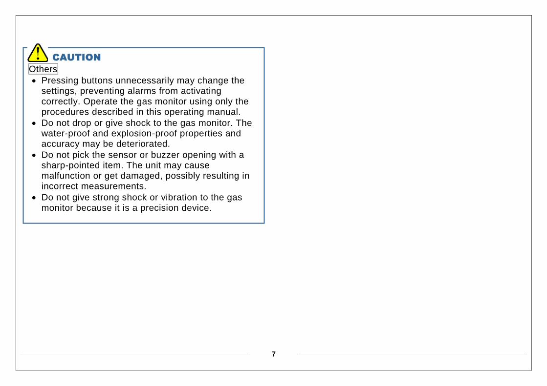
CAUTION
Others
Pressing buttons unnecessarily may change the settings, preventing alarms from activating correctly. Operate the gas monitor using only the procedures described in this operating manual.
Do not drop or give shock to the gas monitor. The water-proof and explosion-proof properties and accuracy may be deteriorated.
Do not pick the sensor or buzzer opening with a sharp-pointed item. The unit may cause malfunction or get damaged, possibly resulting in incorrect measurements.
Do not give strong shock or vibration to the gas monitor because it is a precision device.
8
3
Product Components
3-1. Checking the package
After unpacking, be sure to check that all the
accessories are included in the package.
HS-03 (the main unit)
Rubber protection cover (pre-attached to the main unit)
Alligator clip (pre-attached to the main unit)
Batteries (pre-installed in the main unit)
Operating manual (this document)
9
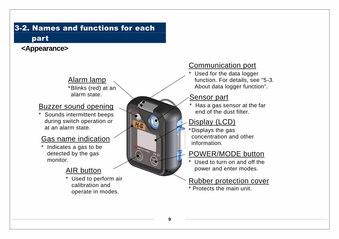
3-2. Names and functions for each
part
<Appearance>
Buzzer sound opening * Sounds intermittent beeps
during switch operation or at an alarm state.
Sensor part * Has a gas sensor at the far
end of the dust filter.
Display (LCD) * Displays the gas concentration and other information.
POWER/MODE button * Used to turn on and off the
power and enter modes. AIR button * Used to perform air
calibration and operate in modes.
Alarm lamp * Blinks (red) at an alarm state.
Gas name indication * Indicates a gas to be
detected by the gas monitor.
Rubber protection cover * Protects the main unit.
Communication port * Used for the data logger
function. For details, see "5-3. About data logger function".
10
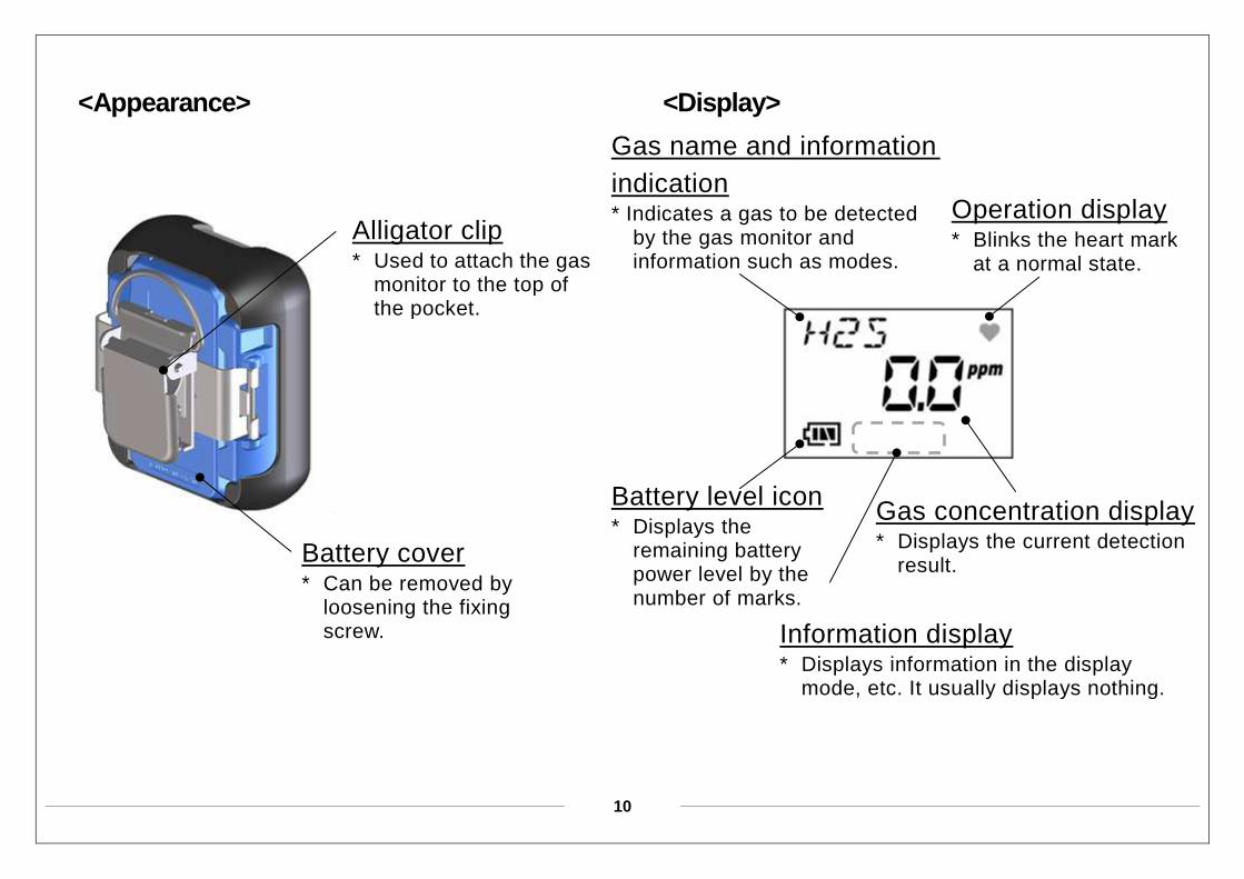
<Appearance>
<Display>
Battery cover * Can be removed by
loosening the fixing screw.
Alligator clip * Used to attach the gas
monitor to the top of the pocket.
Information display * Displays information in the display
mode, etc. It usually displays nothing.
Gas name and information
indication * Indicates a gas to be detected
by the gas monitor and information such as modes.
Battery level icon * Displays the
remaining battery power level by the number of marks.
Operation display * Blinks the heart mark
at a normal state.
Gas concentration display * Displays the current detection
result.
11
4
How to Use
4-1. Preparation for start-up
Before use, read and understand the
following precautions. Ignoring these
precautions may prevent correct operations.
Check that the batteries are installed.
Check that the dust filter is free of dust.
Check that the gas monitor is not damaged.
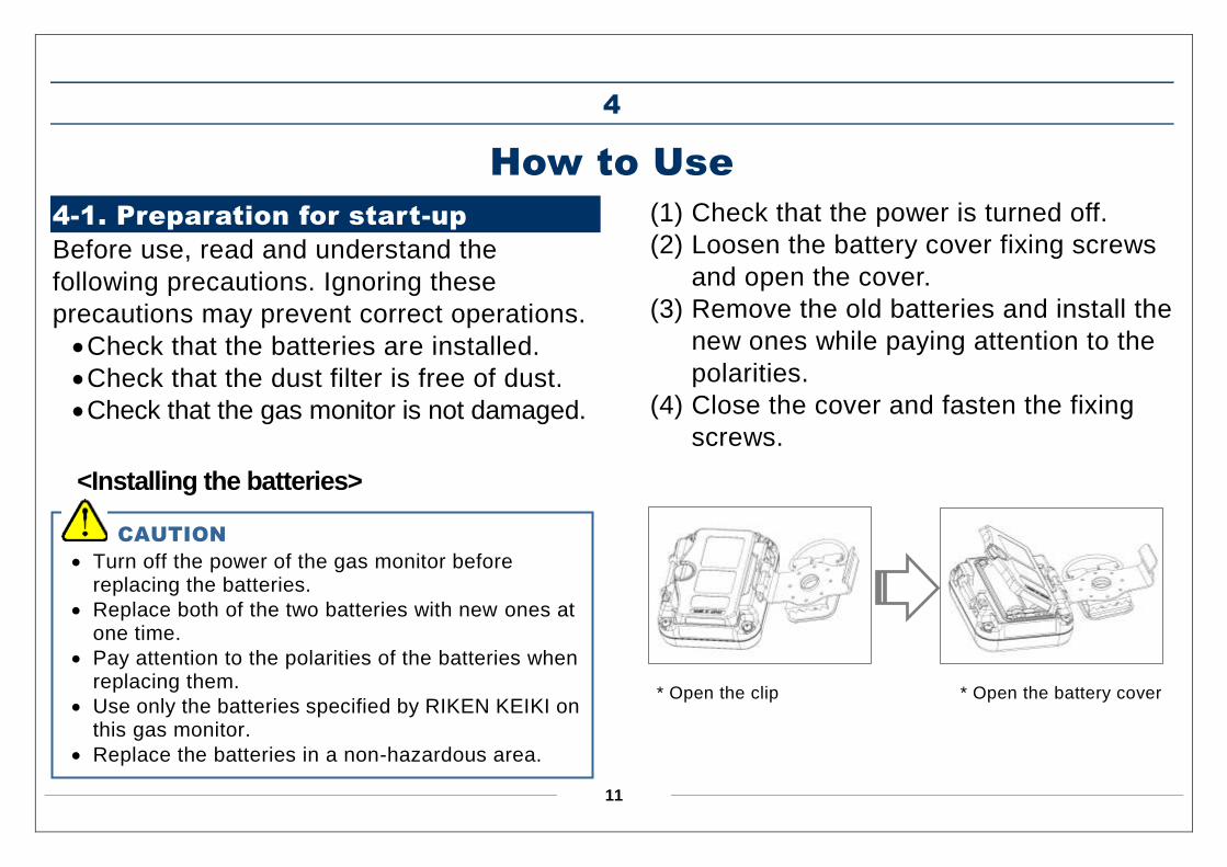
<Installing the batteries>
(1) Check that the power is turned off.
(2) Loosen the battery cover fixing screws
and open the cover.
(3) Remove the old batteries and install the
new ones while paying attention to the
polarities.
(4) Close the cover and fasten the fixing
screws.
* Open the clip * Open the battery cover
CAUTION
Turn off the power of the gas monitor before replacing the batteries.
Replace both of the two batteries with new ones at one time.
Pay attention to the polarities of the batteries when replacing them.
Use only the batteries specified by RIKEN KEIKI on this gas monitor.
Replace the batteries in a non-hazardous area.
12
4-2. Power-on and power-off
<How to power-on>
Press the POWER button until the buzzer
blips. After the LCD display switches as
follows, the gas monitor enters the detection
mode.
All lights ON->Date and time->Battery
voltage->Detection range->1st alarm
setpoint value->2nd alarm setpoint
value->STEL alarm setpoint value->TWA
alarm setpoint value->Detection mode (Blip
Blip)
NOTE
When powering on after leaving the gas monitor for more than five minutes with the batteries removed, such as when powering on for the first time or replacing the batteries, the monitor enters the clock adjustment mode. In this case, see "6-2-1. Time settings" to set the date and time.
NOTE
When the communication port of this gas monitor and another gas monitor is in the place of symmetrical, do not turn on the power. The status of gas monitor suddenly may move the communication mode "TRANS PC". In that case, turn off the power once. After that, then turn it on again. At that time, so as the each other communication port is not to the place of symmetrical, be careful.
<How to power-off>
Keep the POWER button pressed until the
buzzer blips three times (Blip Blip Blip) from
the TURN - OFF display and the LCD turns
off.
13
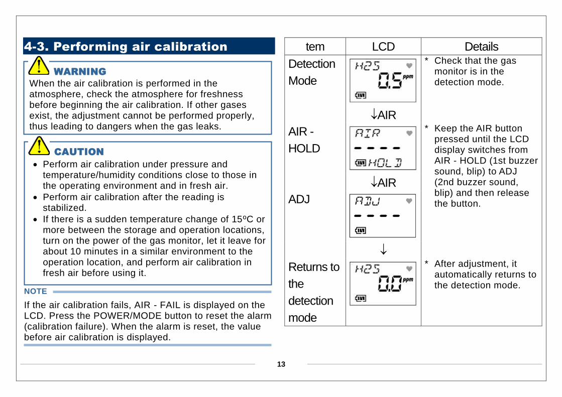
4-3. Performing air calibration
NOTE
If the air calibration fails, AIR - FAIL is displayed on the LCD. Press the POWER/MODE button to reset the alarm (calibration failure). When the alarm is reset, the value before air calibration is displayed.
tem LCD Details
Detection
Mode
* Check that the gas monitor is in the detection mode.
AIR
AIR -
HOLD
* Keep the AIR button pressed until the LCD display switches from AIR - HOLD (1st buzzer sound, blip) to ADJ (2nd buzzer sound, blip) and then release the button.
AIR
ADJ
Returns to
the
detection
mode
* After adjustment, it automatically returns to the detection mode.
WARNING
When the air calibration is performed in the atmosphere, check the atmosphere for freshness before beginning the air calibration. If other gases exist, the adjustment cannot be performed properly, thus leading to dangers when the gas leaks.
CAUTION
Perform air calibration under pressure and temperature/humidity conditions close to those in the operating environment and in fresh air.
Perform air calibration after the reading is stabilized.
If there is a sudden temperature change of 15ºC or more between the storage and operation locations, turn on the power of the gas monitor, let it leave for about 10 minutes in a similar environment to the operation location, and perform air calibration in fresh air before using it.
14
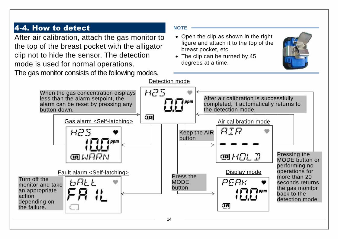
4-4. How to detect
After air calibration, attach the gas monitor to
the top of the breast pocket with the alligator
clip not to hide the sensor. The detection
mode is used for normal operations.
The gas monitor consists of the following modes.
NOTE Open the clip as shown in the right
figure and attach it to the top of the breast pocket, etc.
The clip can be turned by 45 degrees at a time.
When the gas concentration displays less than the alarm setpoint, the alarm can be reset by pressing any button down.
Turn off the monitor and take an appropriate action depending on the failure.
After air calibration is successfully completed, it automatically returns to the detection mode.
Detection mode
Air calibration mode
Display mode
Gas alarm <Self-latching>
Fault alarm <Self-latching> Press the MODE button
Pressing the MODE button or performing no operations for more than 20 seconds returns the gas monitor back to the detection mode.
Keep the AIR button pressed
15
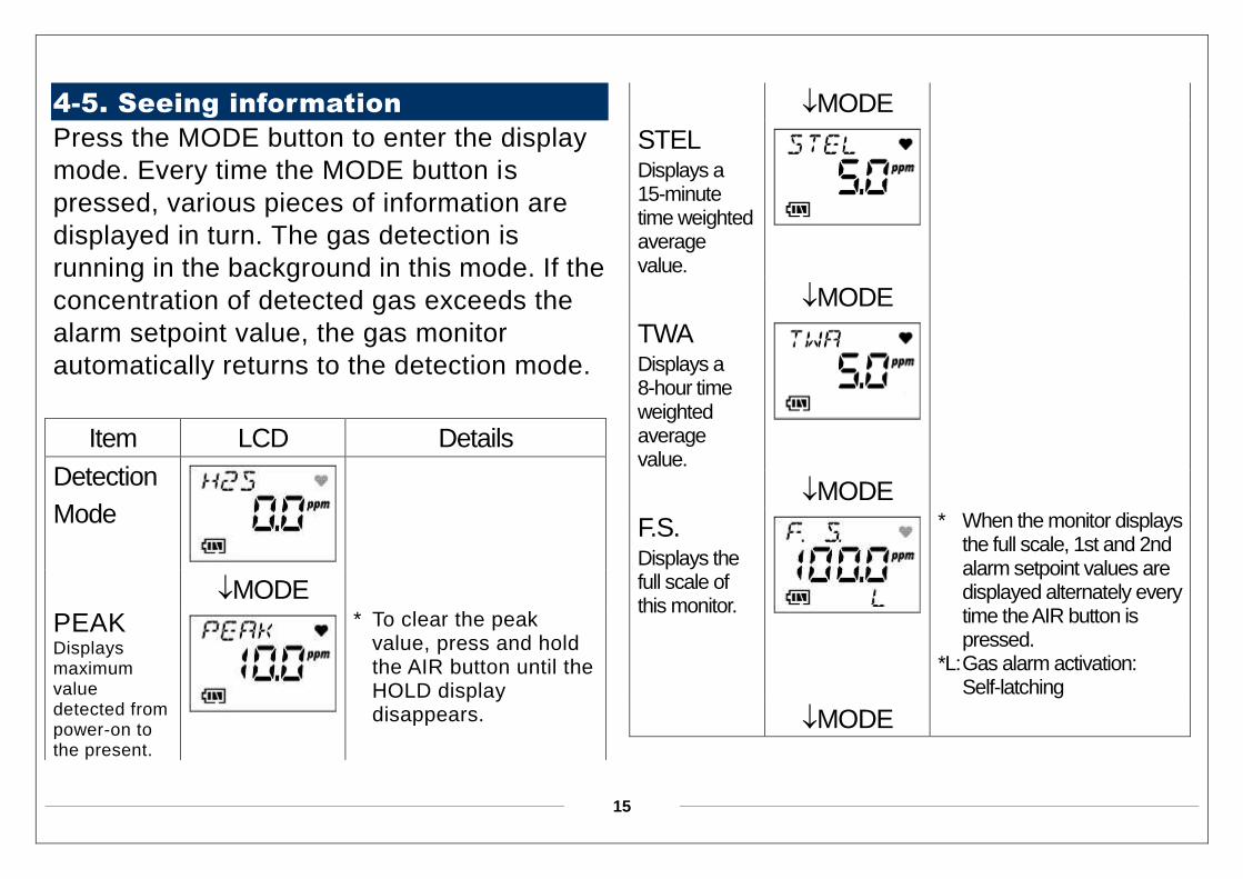
4-5. Seeing information
Press the MODE button to enter the display
mode. Every time the MODE button is
pressed, various pieces of information are
displayed in turn. The gas detection is
running in the background in this mode. If the
concentration of detected gas exceeds the
alarm setpoint value, the gas monitor
automatically returns to the detection mode.
Item LCD Details
Detection
Mode
MODE
PEAK Displays maximum value detected from power-on to the present.
* To clear the peak value, press and hold the AIR button until the HOLD display disappears.
MODE
STEL Displays a 15-minute time weighted average value.
MODE
TWA Displays a 8-hour time weighted average value.
MODE
F.S. Displays the full scale of this monitor.
* When the monitor displays the full scale, 1st and 2nd alarm setpoint values are displayed alternately every time the AIR button is pressed.
*L: Gas alarm activation: Self-latching
MODE
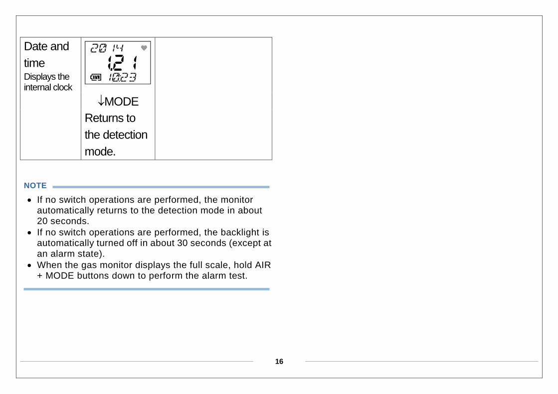
16
Date and
time Displays the internal clock
MODE
Returns to
the detection
mode.
NOTE
If no switch operations are performed, the monitor automatically returns to the detection mode in about 20 seconds.
If no switch operations are performed, the backlight is automatically turned off in about 30 seconds (except at an alarm state).
When the gas monitor displays the full scale, hold AIR + MODE buttons down to perform the alarm test.
17
5
Operations and Functions
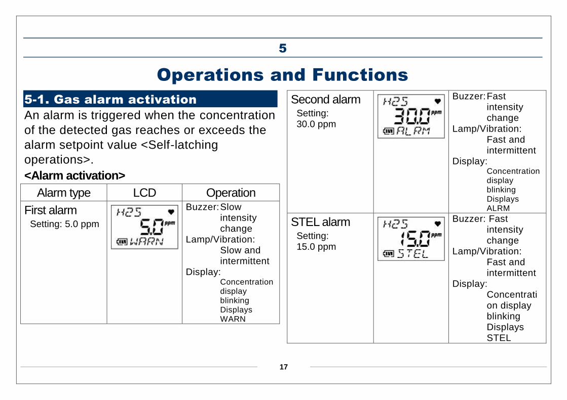
5-1. Gas alarm activation
An alarm is triggered when the concentration
of the detected gas reaches or exceeds the
alarm setpoint value <Self-latching
operations>.
<Alarm activation>
Alarm type LCD Operation
First alarm Setting: 5.0 ppm
Buzzer: Slow intensity change
Lamp/Vibration: Slow and intermittent
Display: Concentration display blinking Displays WARN
Second alarm Setting: 30.0 ppm
Buzzer: Fast intensity change
Lamp/Vibration: Fast and intermittent
Display: Concentration display blinking Displays ALRM
STEL alarm Setting: 15.0 ppm
Buzzer: Fast intensity change
Lamp/Vibration: Fast and intermittent
Display: Concentration display blinking Displays STEL

18
TWA alarm
Setting: 10.0 ppm
Buzzer: Fast intensity change
Lamp/Vibration: Fast and intermittent
Display: Concentration display blinking Displays TWA
Over alarm
Setting:
100.0 ppm
Buzzer: Fast intensity change
Lamp/Vibration: Fast and intermittent
Display: Concentration display blinking Displays OVER
<How to reset the alarm>
After the concentration of detected gas
settles below the alarm setpoint value, press
any button to reset the gas alarm.
NOTE
Even if the concentration of detected gas exceeds the alarm setpoint value, the operations of buzzer, lamp and vibration continue (self-latching) until any button is pressed (the alarm is reset).
The alarming type of OVER alarm is self-latching (even the OVER display is latched). Press any button to reset the alarm. If the gas concentration is lower than the full scale at the reset, the gas concentration display appears again. If it is over the full scale, an OVER alarm occurs again.
19
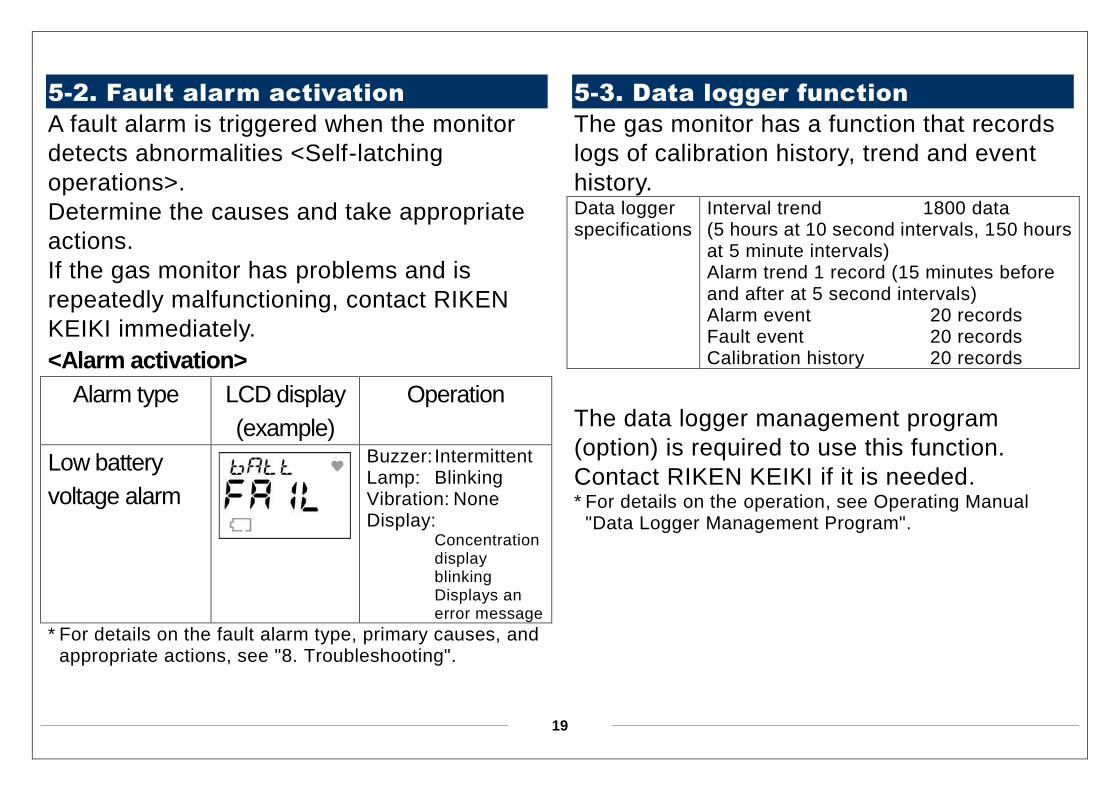
5-2. Fault alarm activation
A fault alarm is triggered when the monitor
detects abnormalities <Self-latching
operations>.
Determine the causes and take appropriate
actions.
If the gas monitor has problems and is
repeatedly malfunctioning, contact RIKEN
KEIKI immediately.
<Alarm activation>
Alarm type LCD display
(example)
Operation
Low battery
voltage alarm
Buzzer: Intermittent Lamp: Blinking Vibration: None Display:
Concentration display blinking Displays an error message
* For details on the fault alarm type, primary causes, and appropriate actions, see "8. Troubleshooting".
5-3. Data logger function
The gas monitor has a function that records
logs of calibration history, trend and event
history.
The data logger management program
(option) is required to use this function.
Contact RIKEN KEIKI if it is needed. * For details on the operation, see Operating Manual
"Data Logger Management Program".
Data logger specifications
Interval trend 1800 data (5 hours at 10 second intervals, 150 hours at 5 minute intervals) Alarm trend 1 record (15 minutes before and after at 5 second intervals) Alarm event 20 records Fault event 20 records Calibration history 20 records
20
6
Maintenance
The gas monitor is an important instrument
for the purpose of safety.
To maintain the performance of the gas
monitor and improve the reliability of safety,
perform a regular maintenance.
Contact RIKEN KEIKI if it is needed.
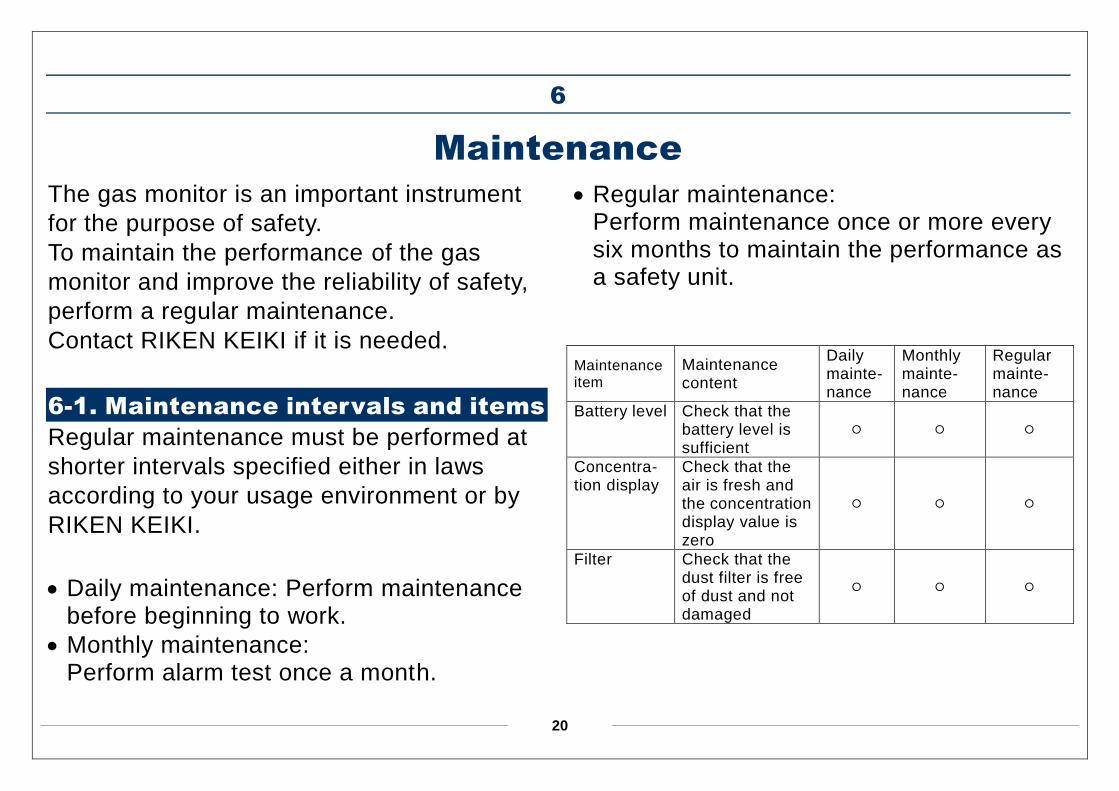
6-1. Maintenance intervals and items
Regular maintenance must be performed at
shorter intervals specified either in laws
according to your usage environment or by
RIKEN KEIKI.
Daily maintenance: Perform maintenance before beginning to work.
Monthly maintenance: Perform alarm test once a month.
Regular maintenance: Perform maintenance once or more every six months to maintain the performance as a safety unit.
Maintenance item
Maintenance content
Daily mainte- nance
Monthly mainte- nance
Regular mainte- nance
Battery level Check that the battery level is sufficient
○ ○ ○
Concentra- tion display
Check that the air is fresh and the concentration display value is zero
○ ○ ○
Filter Check that the dust filter is free of dust and not damaged
○ ○ ○
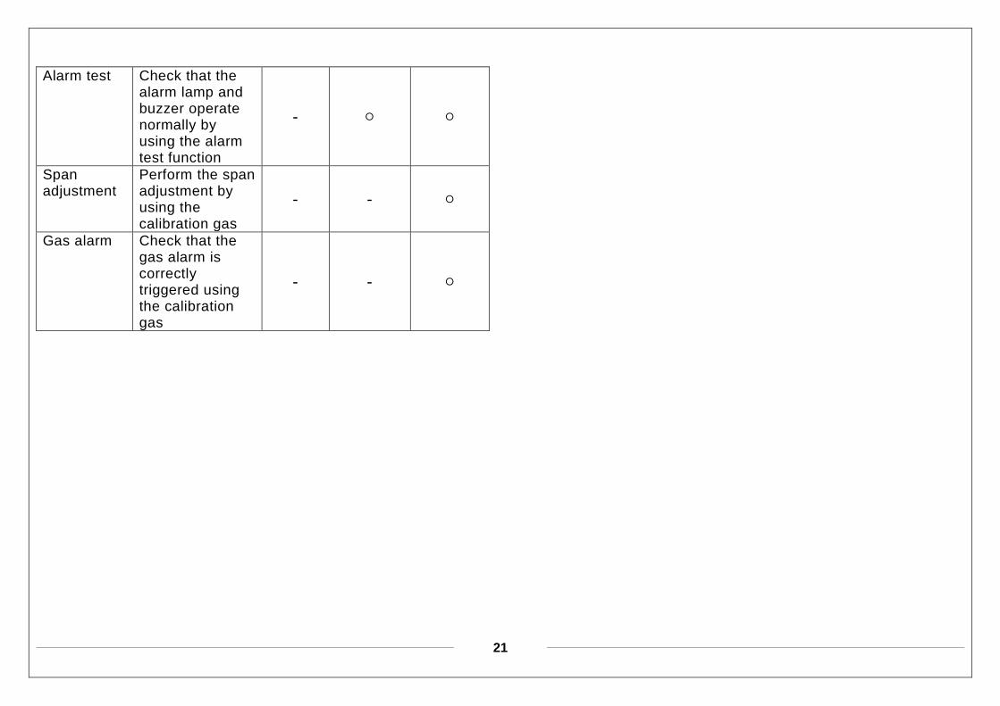
21
Alarm test Check that the alarm lamp and buzzer operate normally by using the alarm test function
- ○ ○
Span adjustment
Perform the span adjustment by using the calibration gas
- - ○
Gas alarm Check that the gas alarm is correctly triggered using the calibration gas
- - ○
22
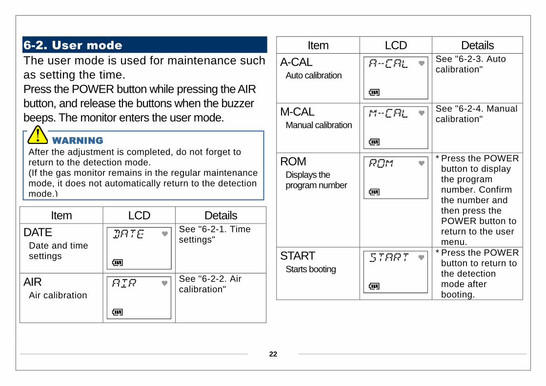
6-2. User mode
The user mode is used for maintenance such
as setting the time.
Press the POWER button while pressing the AIR
button, and release the buttons when the buzzer
beeps. The monitor enters the user mode.
Item LCD Details
DATE Date and time settings
See "6-2-1. Time settings"
AIR Air calibration
See "6-2-2. Air calibration"
Item LCD Details
A-CAL Auto calibration
See "6-2-3. Auto calibration"
M-CAL Manual calibration
See "6-2-4. Manual calibration"
ROM Displays the program number
* Press the POWER button to display the program number. Confirm the number and then press the POWER button to return to the user menu.
START Starts booting
* Press the POWER button to return to the detection mode after booting.
WARNING
After the adjustment is completed, do not forget to return to the detection mode. (If the gas monitor remains in the regular maintenance mode, it does not automatically return to the detection mode.)
23
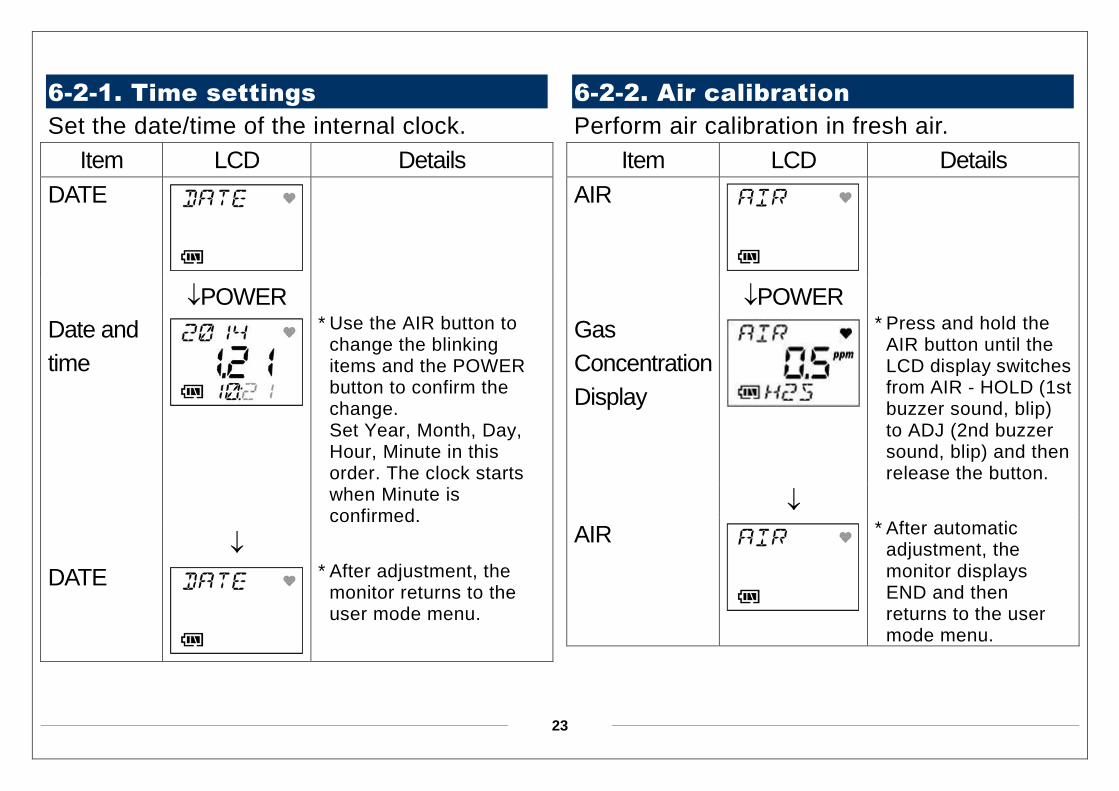
6-2-1. Time settings
Set the date/time of the internal clock.
Item LCD Details
DATE
POWER
Date and
time
* Use the AIR button to change the blinking items and the POWER button to confirm the change. Set Year, Month, Day, Hour, Minute in this order. The clock starts when Minute is confirmed.
DATE
* After adjustment, the monitor returns to the user mode menu.
6-2-2. Air calibration
Perform air calibration in fresh air.
Item LCD Details
AIR
POWER
Gas
Concentration
Display
* Press and hold the AIR button until the LCD display switches from AIR - HOLD (1st buzzer sound, blip) to ADJ (2nd buzzer sound, blip) and then release the button.
AIR
* After automatic adjustment, the monitor displays END and then returns to the user mode menu.
24
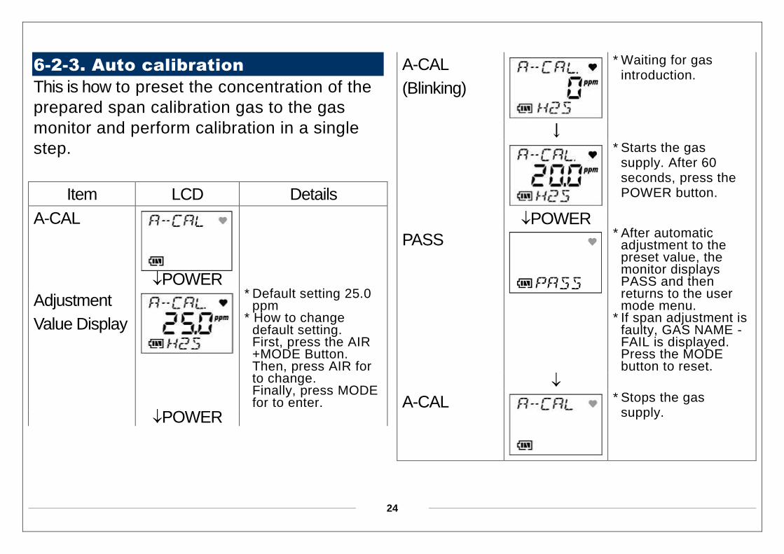
6-2-3. Auto calibration
This is how to preset the concentration of the
prepared span calibration gas to the gas
monitor and perform calibration in a single
step.
Item LCD Details
A-CAL
POWER
Adjustment
Value Display
* Default setting 25.0
ppm * How to change
default setting. First, press the AIR +MODE Button. Then, press AIR for to change. Finally, press MODE for to enter.
POWER
A-CAL
(Blinking)
* Waiting for gas introduction.
↓
* Starts the gas supply. After 60 seconds, press the POWER button.
POWER
PASS
* After automatic adjustment to the preset value, the monitor displays PASS and then returns to the user mode menu.
* If span adjustment is faulty, GAS NAME - FAIL is displayed. Press the MODE button to reset.
A-CAL
* Stops the gas supply.
25
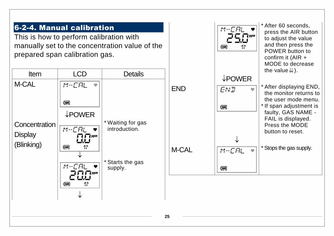
6-2-4. Manual calibration
This is how to perform calibration with
manually set to the concentration value of the
prepared span calibration gas.
Item LCD Details
M-CAL
POWER
Concentration
Display
(Blinking)
* Waiting for gas introduction.
* Starts the gas supply.
* After 60 seconds, press the AIR button to adjust the value and then press the POWER button to confirm it (AIR + MODE to decrease the value ).
POWER
END
* After displaying END, the monitor returns to the user mode menu.
* If span adjustment is faulty, GAS NAME - FAIL is displayed. Press the MODE button to reset.
M-CAL
* Stops the gas supply.
26
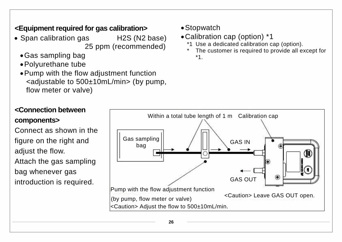
<Equipment required for gas calibration>
Span calibration gas H2S (N2 base) 25 ppm (recommended)
Gas sampling bag
Polyurethane tube
Pump with the flow adjustment function <adjustable to 500±10mL/min> (by pump, flow meter or valve)
<Connection between
components>
Connect as shown in the
figure on the right and
adjust the flow.
Attach the gas sampling
bag whenever gas
introduction is required.
Stopwatch
Calibration cap (option) *1 *1 Use a dedicated calibration cap (option). * The customer is required to provide all except for
*1.
Gas sampling bag
Within a total tube length of 1 m Calibration cap
GAS IN
GAS OUT
Pump with the flow adjustment function
(by pump, flow meter or valve)
<Caution> Adjust the flow to 500±10mL/min.
<Caution> Leave GAS OUT open.
27
6-3. How to clean
Clean the gas monitor if it becomes
extremely dirty. The gas monitor must be
turned off while cleaning it. Use a waste cloth
etc., to remove dust.
Do not use water or organic solvent for
cleaning because they may cause
malfunctions.
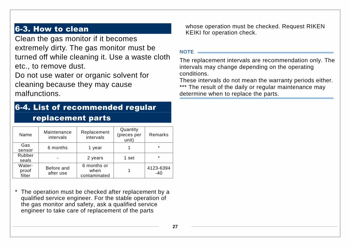
6-4. List of recommended regular
replacement parts
Name Maintenance
intervals Replacement
intervals
Quantity (pieces per
unit) Remarks
Gas sensor
6 months 1 year 1 *
Rubber seals
- 2 years 1 set *
Water- proof filter
Before and after use
6 months or when
contaminated 1
4123-6394-40
* The operation must be checked after replacement by a
qualified service engineer. For the stable operation of the gas monitor and safety, ask a qualified service engineer to take care of replacement of the parts
whose operation must be checked. Request RIKEN KEIKI for operation check.
NOTE
The replacement intervals are recommendation only. The intervals may change depending on the operating conditions. These intervals do not mean the warranty periods either. *** The result of the daily or regular maintenance may determine when to replace the parts.
28
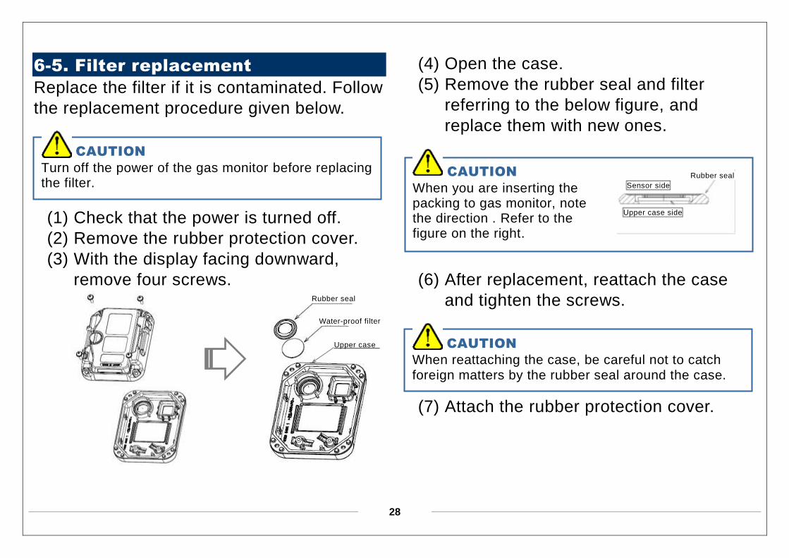
6-5. Filter replacement
Replace the filter if it is contaminated. Follow
the replacement procedure given below.
(1) Check that the power is turned off.
(2) Remove the rubber protection cover.
(3) With the display facing downward,
remove four screws.
(4) Open the case.
(5) Remove the rubber seal and filter
referring to the below figure, and
replace them with new ones.
(6) After replacement, reattach the case
and tighten the screws.
(7) Attach the rubber protection cover.
CAUTION
Turn off the power of the gas monitor before replacing the filter.
CAUTION
When reattaching the case, be careful not to catch foreign matters by the rubber seal around the case.
Rubber seal
Water-proof filter
Upper case
CAUTION
When you are inserting the packing to gas monitor, note the direction . Refer to the figure on the right.
Rubber seal
Filter CF-1821
Sensor side
Upper case side

29
7
Storage and Disposal
7-1. Procedures to store the gas
monitor or leave it for a long time
The gas monitor must be stored under the
following environmental conditions.
(1) In a dark place under the normal
temperature and humidity away from
direct sunlight
(2) In a place where gases, solvents or
vapors are not present
Store the gas monitor in a shipping carton, if
any, in which the product was delivered.
Store the gas monitor away from dust, etc., if
the shipping carton is not available.
7-2. Procedures to use the gas
monitor again
When you use a stopped or stored gas
monitor again, never fail to perform a gas
calibration. For information on readjustment
including gas calibration, please contact
RIKEN KEIKI.
CAUTION
If the gas monitor is not used for a long time, store it after removing the batteries. Battery leaks may result in fire or injury.
30
7-3. Disposal of products
When the gas monitor is disposed of, it must
be treated properly as an industrial waste in
accordance with the local regulations.
<Disposal of Batteries>
• When disposing of the gas monitor in EU
member states, sort the batteries as
specified. Handle the removed batteries
according to the classified refuse collection
system and recycling system based on the
regulations of EU member states. Contact
RIKEN KEIKI to dispose of the gas monitor.
31
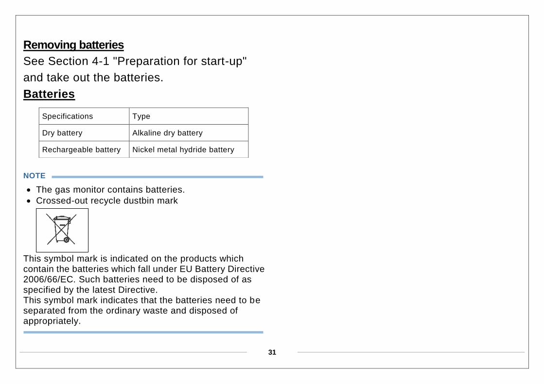
Removing batteries
See Section 4-1 "Preparation for start-up"
and take out the batteries.
Batteries
NOTE
The gas monitor contains batteries.
Crossed-out recycle dustbin mark
This symbol mark is indicated on the products which contain the batteries which fall under EU Battery Directive 2006/66/EC. Such batteries need to be disposed of as specified by the latest Directive. This symbol mark indicates that the batteries need to be separated from the ordinary waste and disposed of appropriately.
Specifications Type
Dry battery Alkaline dry battery
Rechargeable battery Nickel metal hydride battery
32
8
Troubleshooting
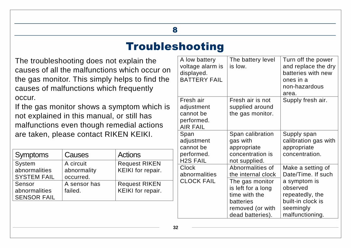
The troubleshooting does not explain the
causes of all the malfunctions which occur on
the gas monitor. This simply helps to find the
causes of malfunctions which frequently
occur.
If the gas monitor shows a symptom which is
not explained in this manual, or still has
malfunctions even though remedial actions
are taken, please contact RIKEN KEIKI.
Symptoms Causes Actions System abnormalities SYSTEM FAIL
A circuit abnormality occurred.
Request RIKEN KEIKI for repair.
Sensor abnormalities SENSOR FAIL
A sensor has failed.
Request RIKEN KEIKI for repair.
A low battery voltage alarm is displayed. BATTERY FAIL
The battery level is low.
Turn off the power and replace the dry batteries with new ones in a non-hazardous area.
Fresh air adjustment cannot be performed. AIR FAIL
Fresh air is not supplied around the gas monitor.
Supply fresh air.
Span adjustment cannot be performed. H2S FAIL
Span calibration gas with appropriate concentration is not supplied.
Supply span calibration gas with appropriate concentration.
Clock abnormalities CLOCK FAIL
Abnormalities of the internal clock
Make a setting of Date/Time. If such a symptom is observed repeatedly, the built-in clock is seemingly malfunctioning.
The gas monitor is left for a long time with the batteries removed (or with dead batteries).
33
9
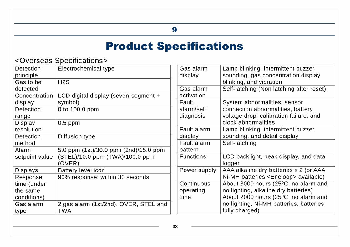
Product Specifications
<Overseas Specifications> Detection principle
Electrochemical type
Gas to be detected
H2S
Concentration display
LCD digital display (seven-segment + symbol)
Detection range
0 to 100.0 ppm
Display resolution
0.5 ppm
Detection method
Diffusion type
Alarm setpoint value
5.0 ppm (1st)/30.0 ppm (2nd)/15.0 ppm (STEL)/10.0 ppm (TWA)/100.0 ppm (OVER)
Displays Battery level icon
Response time (under the same conditions)
90% response: within 30 seconds
Gas alarm type
2 gas alarm (1st/2nd), OVER, STEL and TWA
Gas alarm display
Lamp blinking, intermittent buzzer sounding, gas concentration display blinking, and vibration
Gas alarm activation
Self-latching (Non latching after reset)
Fault alarm/self diagnosis
System abnormalities, sensor connection abnormalities, battery voltage drop, calibration failure, and clock abnormalities
Fault alarm display
Lamp blinking, intermittent buzzer sounding, and detail display
Fault alarm pattern
Self-latching
Functions LCD backlight, peak display, and data logger
Power supply AAA alkaline dry batteries x 2 (or AAA Ni-MH batteries <Eneloop> available)
Continuous operating time
About 3000 hours (25ºC, no alarm and no lighting, alkaline dry batteries) About 2000 hours (25ºC, no alarm and no lighting, Ni-MH batteries, batteries fully charged)
34
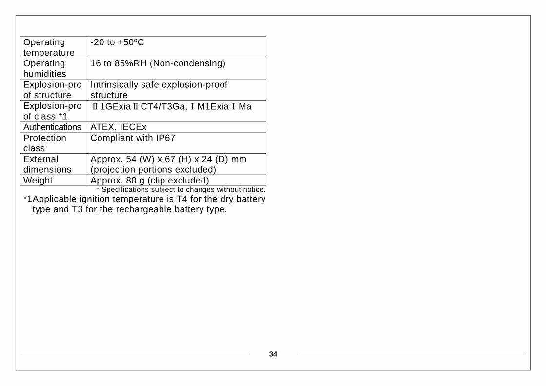
Operating temperature
-20 to +50ºC
Operating humidities
16 to 85%RH (Non-condensing)
Explosion-proof structure
Intrinsically safe explosion-proof structure
Explosion-proof class *1
Ⅱ1GExiaⅡCT4/T3Ga,ⅠM1ExiaⅠMa
Authentications ATEX, IECEx
Protection class
Compliant with IP67
External dimensions
Approx. 54 (W) x 67 (H) x 24 (D) mm (projection portions excluded)
Weight Approx. 80 g (clip excluded) * Specifications subject to changes without notice.
*1 Applicable ignition temperature is T4 for the dry battery type and T3 for the rechargeable battery type.


![Microsensor Measurements ofSulfate Reduction and Sulfide ...Jorgensen1992b.pdf · constants, respectively, of the sulfide equilibrium system, [S2-] is the sulfide concentration, and](https://img.pdfslide.us/doc/110x75/5e9a6d84dc840a57bc1baa83/microsensor-measurements-ofsulfate-reduction-and-sulfide-amp-constants.jpg)