Embed Size (px)
Citation preview

*29010878R005*
PG8WLSHW8 and PG9WLSHW8 IQHardwire PowerG Wired to WirelessConverter Installation Manual
29010878R005

2 PG8WLSHW8 and PG9WLSHW8 IQ Hardwire PowerG Wired to Wireless Converter Installation Manual
ContentsContentsSafety instructions............................................................................................................................................5Introduction...................................................................................................................................................... 6Technical Specifications...................................................................................................................................7Installing the equipment.................................................................................................................................9
Mounting the module......................................................................................................................... 10Mounting the enclosure............................................................................................................................ 10Mounting the power adapter................................................................................................................... 10
Wiring the zones.................................................................................................................................. 12Normally open and normally closed wiring............................................................................................13Single end-of-line resistors....................................................................................................................... 13Double end-of-line resistors..................................................................................................................... 15
Wiring programmable outputs.......................................................................................................... 16Wiring a fire zone to the PGM2 configured as a 2-wire loop................................................................ 17Wiring a 4-wire smoke, heat, or CO detector..........................................................................................19
Wiring auxiliary power........................................................................................................................ 20Wiring the bell output......................................................................................................................... 20Installing the battery...........................................................................................................................20Wiring the module...............................................................................................................................21
Wiring the power supply........................................................................................................................... 21Wiring the battery...................................................................................................................................... 21Wiring a keypad/HSM2108/HSM2300......................................................................................................22Silencing fire alarm or CO alarm bells..................................................................................................... 24
Enrolling the module..................................................................................................................................... 25Testing the module placement.......................................................................................................... 25
Enrolling wired zones automatically............................................................................................................26Enrolling a keypad/zone expander/power supply.....................................................................................27Attaching the cover........................................................................................................................................ 28Status LEDs......................................................................................................................................................29Troubleshooting............................................................................................................................................. 30Wiring diagram...............................................................................................................................................31FCC and ISED Canada Information.............................................................................................................. 32
Modification statement.......................................................................................................................32Interference statement.......................................................................................................................32Wireless notice..................................................................................................................................... 32
FCC class B digital device notice................................................................................................................... 33UL and ULC notes........................................................................................................................................... 34
UL commercial and residential installation requirements and considerations...........................34UL commercial, UL household, and ULC security level I and II burglar alarm unit.....................34UL and ULC household fire warning system.................................................................................... 34
European CE Compliance and CERTALARM Certification.......................................................................... 35
PG8WLSHW8 and PG9WLSHW8 IQ Hardwire PowerG Wired to Wireless Converter Installation Manual 3
Simplified EU declaration of conformity........................................................................................... 35EULA.................................................................................................................................................................36
SOFTWARE PRODUCT LICENSE.......................................................................................................... 36Limited warranty............................................................................................................................................ 39
International Warranty....................................................................................................................... 39Warranty Procedure............................................................................................................................ 39Conditions to Void Warranty.............................................................................................................. 39Items Not Covered by Warranty........................................................................................................ 39Disclaimer of Warranties.................................................................................................................... 40Out of Warranty Repairs..................................................................................................................... 40
Trademark.......................................................................................................................................................41
PG8WLSHW8 and PG9WLSHW8 IQ Hardwire PowerG Wired to Wireless Converter Installation Manual4
Safety instructionsRead the safety information before you install the equipment.
Important: This equipment must be installed by a skilled person only. A skilled person is aninstaller with appropriate technical training. The installer must be aware of potential hazardsduring installation and measures available to minimize risks to the installer and other people.
• Before you install this equipment, disconnect all power sources (for example mains, battery,and telephone line) connected to the alarm panel.
• Install the equipment indoors in a non-hazardous environment where the followingconditions are met:
- Pollution degree - Maximum 2- Over voltages - Category II
• Internal wiring must be routed to prevent strain on wire and terminal connections, looseterminal connections, and damage to conductor insulation.
• Instruct the user that there are no user serviceable parts in this equipment. All equipmentmust be serviced by a skilled person.
• Skilled persons are persons who have training or experience in the equipment technology,particularly the various energies and energy magnitudes used in the equipment. Skilledpersons are expected to use their training and experience to recognize energy sourcescapable of causing pain or injury and to take action for protection from injury. Skilled personsare persons who have training or experience in the equipment technology, particularly thevarious energies and energy magnitudes used in the equipment. Skilled persons are expectedto use their training and experience to recognize energy sources capable of causing pain orinjury and to take action for protection from injury.
5PG8WLSHW8 and PG9WLSHW8 IQ Hardwire PowerG Wired to Wireless Converter Installation Manual
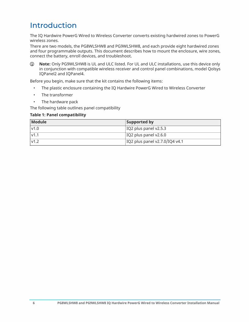
IntroductionThe IQ Hardwire PowerG Wired to Wireless Converter converts existing hardwired zones to PowerGwireless zones.There are two models, the PG8WLSHW8 and PG9WLSHW8, and each provide eight hardwired zonesand four programmable outputs. This document describes how to mount the enclosure, wire zones,connect the battery, enroll devices, and troubleshoot.
Note: Only PG9WLSHW8 is UL and ULC listed. For UL and ULC installations, use this device onlyin conjunction with compatible wireless receiver and control panel combinations, model QolsysIQPanel2 and IQPanel4.
Before you begin, make sure that the kit contains the following items:• The plastic enclosure containing the IQ Hardwire PowerG Wired to Wireless Converter• The transformer• The hardware pack
The following table outlines panel compatibilityTable 1: Panel compatibilityModule Supported byv1.0 IQ2 plus panel v2.5.3v1.1 IQ2 plus panel v2.6.0v1.2 IQ2 plus panel v2.7.0/IQ4 v4.1
PG8WLSHW8 and PG9WLSHW8 IQ Hardwire PowerG Wired to Wireless Converter Installation Manual6

Technical SpecificationsThe following table outlines the electrical ratings of the components of the IQ Hardwire PowerGWired to Wireless Converter.Table 2: Technical specificationsType DescriptionDC input voltage and current Use the provided external power adapter with the following
ratings.Input for UL and ULC applications: 120 VAC, 60 Hz, 1.2AInput for EN50131 applications: 240 VAC (+10%, -15%), 50Hz, 1.2 AOutput: 18 VDC, 2.22 AManufacturer: ShenZhen SOY Technology Co. Ltd.UL and ULC Model: SOY-1800222USDSC UL and ULC part number: PGWLSH40A, HS40WPSA &HS40WPSNAEN model: SOY-1800222-EUDSC EN part number: PGWLSH40C
Battery type Sealed, rechargeable lead acidBattery charging voltage andcurrent
13.7 VDC, 360 mA
Low battery threshold 11.4 VDCBattery cutoff level 9.6 VDC ± 2%PCB assembly current consumption 70 mAStandby battery Only use the battery rated 12 VDC/ 7 Ah
The energy level of the battery when it is charged is 100%24-hour standby time and 5-minute alarm time for UL andULC residential fire applications and ULC Security Level IIapplications.
Note: The AUX current must not exceed 180 mA.24-hour standby time and 5-minute alarm time for UL andULC residential fire applications and 12-hour CO alarm.
Note: The AUX current must not exceed 110 mA.4-hour standby time and 5-minute alarm time for UL andULC residential burglary applications.
Note: The AUX current must not exceed 700 mA.4-hour standby time and 15-minute alarm time for ULcommerical burglary applications.
Note: The AUX current must not exceed 700 mA.
Note: For EN50131 Grade 2 applications, the devices provide12 hours of standby time and recharge in 72 hours. The AUXcurrent load must not exceed 430 mA.
7PG8WLSHW8 and PG9WLSHW8 IQ Hardwire PowerG Wired to Wireless Converter Installation Manual
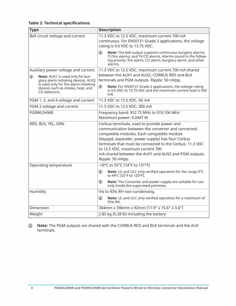
Table 2: Technical specificationsType DescriptionBell circuit voltage and current 11.3 VDC to 12.5 VDC, maximum current 700 mA
continuous. For EN50131 Grade 2 applications, the voltagerating is 9.6 VDC to 13.75 VDC.
Note: The bell output supports continuous burglary alarms,T3 fire alarms, and T4 CO alarms. Alarms sound in the follow-ing priority: fire alarm, CO alarm, burglary alarm, and otheralarms.
Auxiliary power voltage and current.Note: AUX1 is used only for bur-glary alarm initiating devices. AUX2is used only for fire alarm initiatingdevices such as smoke, heat, andCO detectors.
11.3 VDC to 12.5 VDC, maximum current 700 mA sharedbetween the AUX1 and AUX2, CORBUS RED and BLKterminals and PGM outputs. Ripple: 50 mVpp.
Note: For EN50131 Grade 2 applications, the voltage ratingis 9.6 VDC to 13.75 VDC and the maximum current load is 430mA.
PGM 1, 3, and 4 voltage and current 11.3 VDC to 12.5 VDC, 50 mAPGM 2 voltage and current 11.3 VDC to 12.5 VDC, 300 mAPG9WLSHW8 Frequency band: 912.75 MHz to 919.106 MHz
Maximum power: 0.0447 WRED, BLK, YEL, GRN Corbus terminals, used to provide power and
communication between the converter and connectedcompatible modules. Each compatible module(keyapd, expander, power supply) has four Corbusterminals that must be connected to the Corbus. 11.3 VDCto 12.5 VDC, maximum current 700mA shared between the AUX1 and AUX2 and PGM outputs.Ripple: 50 mVpp.
Operating temperature -10°C to 55°C (14°F to 131°F)Note: UL and ULC only verified operation for the range 0°Cto 49°C (32°F to 120°F).
Note: The Converter and power supply are suitable for useonly inside the supervised premises.
Humidity 5% to 93% RH non-condensing.Note: UL and ULC only verified operation for a maximum of93% RH.
Dimension 304mm x 396mm x 92mm (11.9" x 15.6" x 3.6")Weight 2.85 kg (6.28 lb) including the battery
Note: The PGM outputs are shared with the CORBUS RED and BLK terminals and the AUXterminals.
PG8WLSHW8 and PG9WLSHW8 IQ Hardwire PowerG Wired to Wireless Converter Installation Manual8
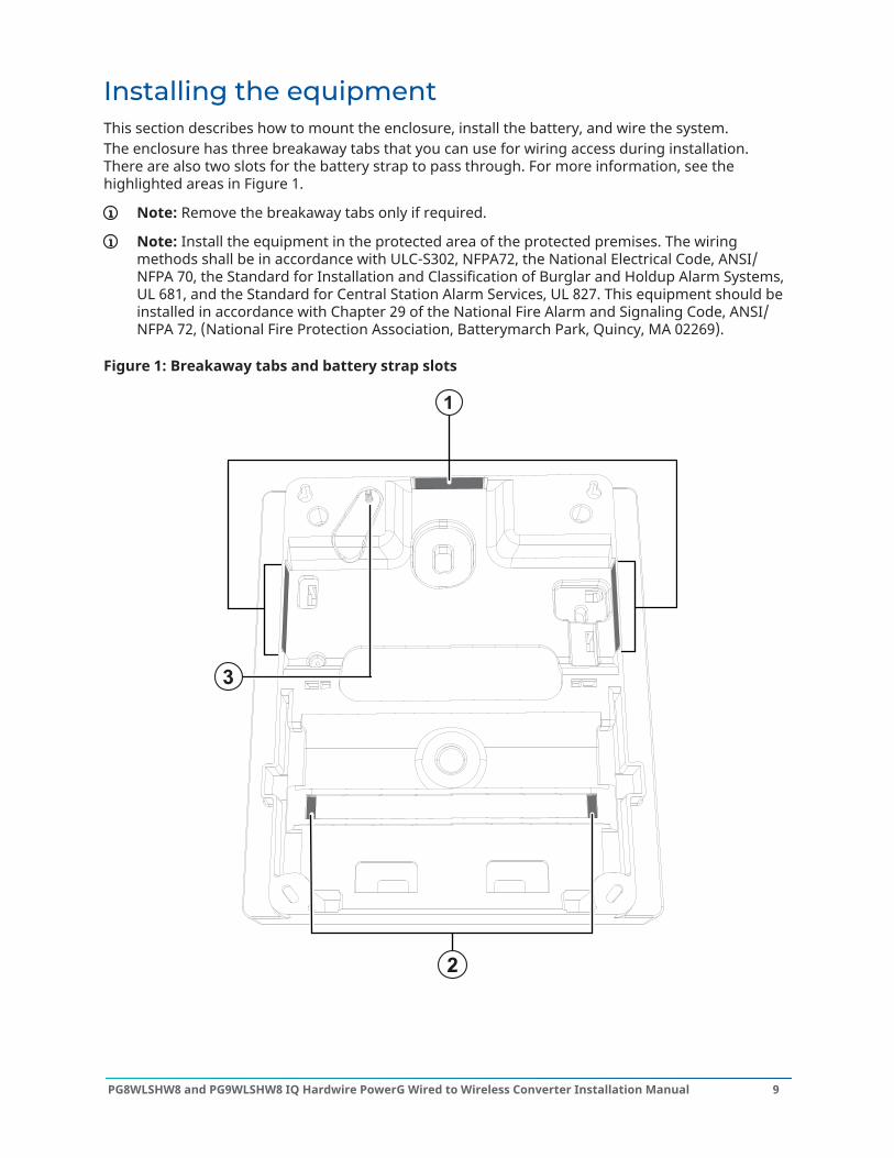
Installing the equipmentThis section describes how to mount the enclosure, install the battery, and wire the system.The enclosure has three breakaway tabs that you can use for wiring access during installation.There are also two slots for the battery strap to pass through. For more information, see thehighlighted areas in Figure 1.
Note: Remove the breakaway tabs only if required.
Note: Install the equipment in the protected area of the protected premises. The wiringmethods shall be in accordance with ULC-S302, NFPA72, the National Electrical Code, ANSI/NFPA 70, the Standard for Installation and Classification of Burglar and Holdup Alarm Systems,UL 681, and the Standard for Central Station Alarm Services, UL 827. This equipment should beinstalled in accordance with Chapter 29 of the National Fire Alarm and Signaling Code, ANSI/NFPA 72, (National Fire Protection Association, Batterymarch Park, Quincy, MA 02269).
Figure 1: Breakaway tabs and battery strap slots
9PG8WLSHW8 and PG9WLSHW8 IQ Hardwire PowerG Wired to Wireless Converter Installation Manual
Callout Description1 Breakaway tabs2 Slots for the battery strap
Note: Securing the battery in the enclosure with the battery strap is optional.The battery strap is sold separately.
3 Wall tamper screw
Mounting the moduleThis section describes how to mount the enclosure and the external power adapter.
Mounting the enclosureTo mount the PG8WLSHW8 and PG9WLSHW8 enclosure, complete the following steps:
1. Use the four ST 6X1/2 type 25 Phil screws provided to secure the enclosure to the wall. Formore information, see the highlighted areas Table in Figure 2.
Note: Screws are provided only for the model PG9WLSHW8.
2. To enable the wall tamper, secure the tamper screw to the wall. For more information, seeFigure 2.
Mounting the power adapterYou must mount the power adapter outside the PGXWLSHW8 enclosure. To mount the poweradapter, complete the following step:
• Use two screws to secure the power adapter to the wall. For more information, see Callout 5in Figure 2.
Note: Mount the power adapter close to an AC power outlet so there is no strain on thepower cable. Do not connect the power adapter to a receptacle controlled by a switch.
Example:
PG8WLSHW8 and PG9WLSHW8 IQ Hardwire PowerG Wired to Wireless Converter Installation Manual10
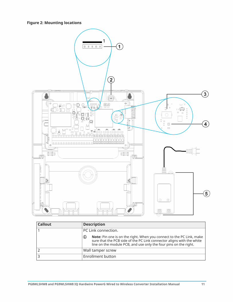
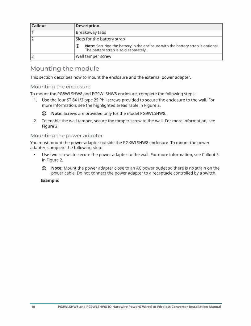
Figure 2: Mounting locations
+-
1
Callout Description1 PC Link connection.
Note: Pin one is on the right. When you connect to the PC Link, makesure that the PCB side of the PC Link connector aligns with the whiteline on the module PCB, and use only the four pins on the right.
2 Wall tamper screw3 Enrollment button
11PG8WLSHW8 and PG9WLSHW8 IQ Hardwire PowerG Wired to Wireless Converter Installation Manual
Callout Description4 Status LED5 Power adapter mounting tabs. Alternate adapter is plug-in style
(HS40WPSA).
Use the following table to determine the distance and gauge for the secondary wiring.Table 3: Wiring distance and gaugeDistance (m/ ft) Gauge (AWG)2/ 6.5 223/ 10 204/ 13 18
For UL and ULC installations, use a primary input with ratings of 120 VAC, 60 Hz, and 1.2 A.
For CE and EN50131 Grade 2 installations, use a primary input with ratings 230 VAC (+10%,-15%), 50 Hz, and 1.2 A.
For all installations, the output rating of the power adapter is 18 VDC and 2.22
A.
Wiring the zonesYou can wire zones to supervise normally open devices, for example smoke detectors orheat detectors, or normally closed devices, for example door contacts. You can program thePG8WLSHW8 or PG9WLSHW8 for single end-of-line (SEOL) resistors, or double end-of-line (DEOL)resistors.
Note: For UL and ULC installations, use only UL and ULC listed initiating devices that arecompatible with the auxiliary output power range provided by the converter.
CAUTION: Ensure the alarm controller is turned off before you wire the equipment.
When you wire zones, observe the following guidelines:• For UL and ULC listed installations, only use SEOL or DEOL connections.• Use a minimum wire size of 22 AWG and a maximum wire size of 18 AWG.• Do not use shielded wires.• Do not exceed a wire resistance of 100 Ω. For more information, see the following table.
Table 4: Wiring chartWire gauge (AWG) Maximum distance to EOL resistor (m/ ft)22 914/ 300020 1493/ 490019 1889/ 620018 2377/ 7800
PG8WLSHW8 and PG9WLSHW8 IQ Hardwire PowerG Wired to Wireless Converter Installation Manual12

Note: Distances are based on a maximum wiring resistance of 100 Ω.
Normally open and normally closed wiringWire normally closed devices in series and normally open devices in parallel. To wire hardwireddevices, complete the following steps:
1. Wire the device to any Zone terminal.2. Wire the device to any COM terminal.
Note: For UL and ULC installations, do not use normally open or normally closed loops.
The following figure shows you how to wire normally closed loops. The image on the left showstwo normally closed contacts with no end-of-line resistor, and the image on the right shows onenormally closed contact with no end-of-line resistor.
Figure 3: Normally closed loops
Callout Description1 Zone terminal2 COM terminal3 Normally closed contact
Note: Do not exceed a wire resistance of 100 Ω. For more information, see Table 4.
The following table shows the zone status for a given resistance value.Table 5: Normally closed zone statusResistance Description Zone status0 Ω Shorted wire, loop shorted SecureInfinite Broken wire, loop open Alarm
Single end-of-line resistorsYou can use SEOL resistors to detect if a circuit is secure, open, or shorted. Use this option if youuse either normally closed or normally open devices.You can configure SEOL supervision through zone programming on the control panel.
13PG8WLSHW8 and PG9WLSHW8 IQ Hardwire PowerG Wired to Wireless Converter Installation Manual
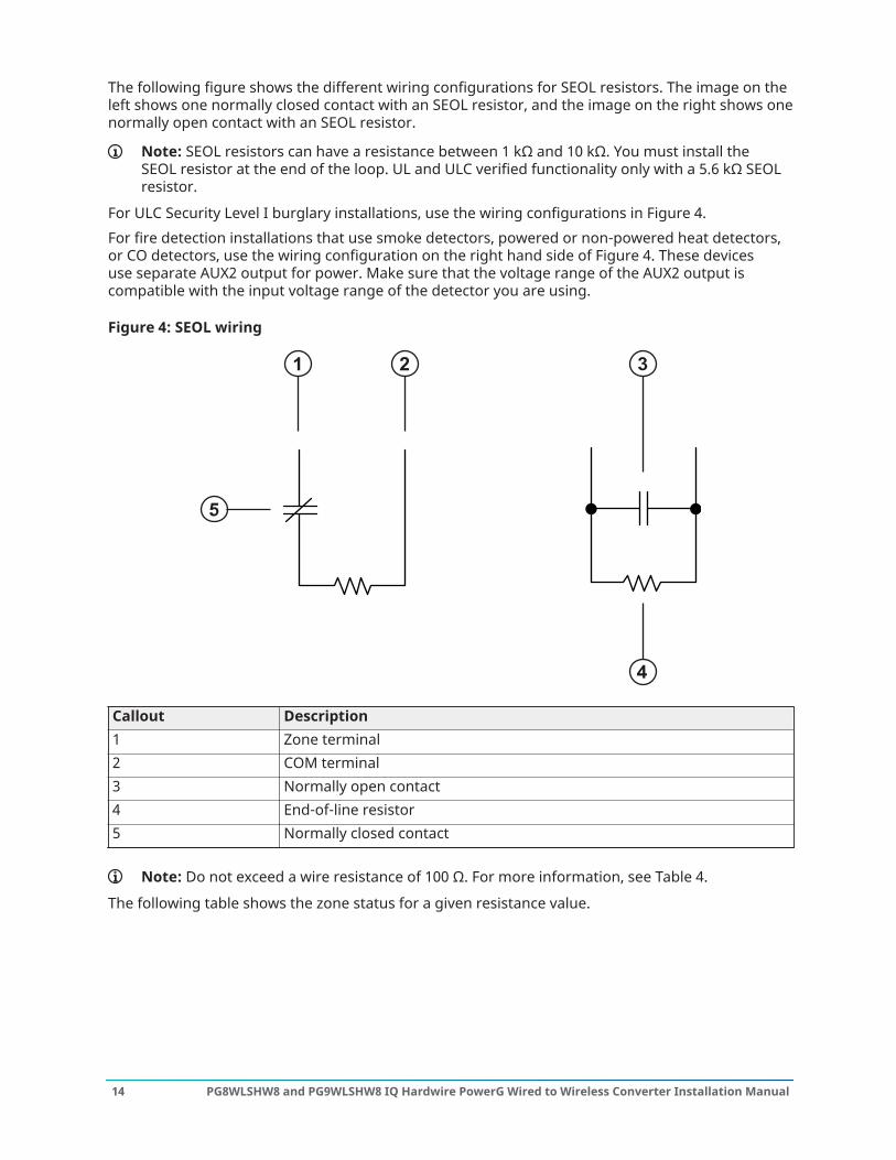
The following figure shows the different wiring configurations for SEOL resistors. The image on theleft shows one normally closed contact with an SEOL resistor, and the image on the right shows onenormally open contact with an SEOL resistor.
Note: SEOL resistors can have a resistance between 1 kΩ and 10 kΩ. You must install theSEOL resistor at the end of the loop. UL and ULC verified functionality only with a 5.6 kΩ SEOLresistor.
For ULC Security Level I burglary installations, use the wiring configurations in Figure 4.For fire detection installations that use smoke detectors, powered or non-powered heat detectors,or CO detectors, use the wiring configuration on the right hand side of Figure 4. These devicesuse separate AUX2 output for power. Make sure that the voltage range of the AUX2 output iscompatible with the input voltage range of the detector you are using.
Figure 4: SEOL wiring
Callout Description1 Zone terminal2 COM terminal3 Normally open contact4 End-of-line resistor5 Normally closed contact
Note: Do not exceed a wire resistance of 100 Ω. For more information, see Table 4.
The following table shows the zone status for a given resistance value.
PG8WLSHW8 and PG9WLSHW8 IQ Hardwire PowerG Wired to Wireless Converter Installation Manual14
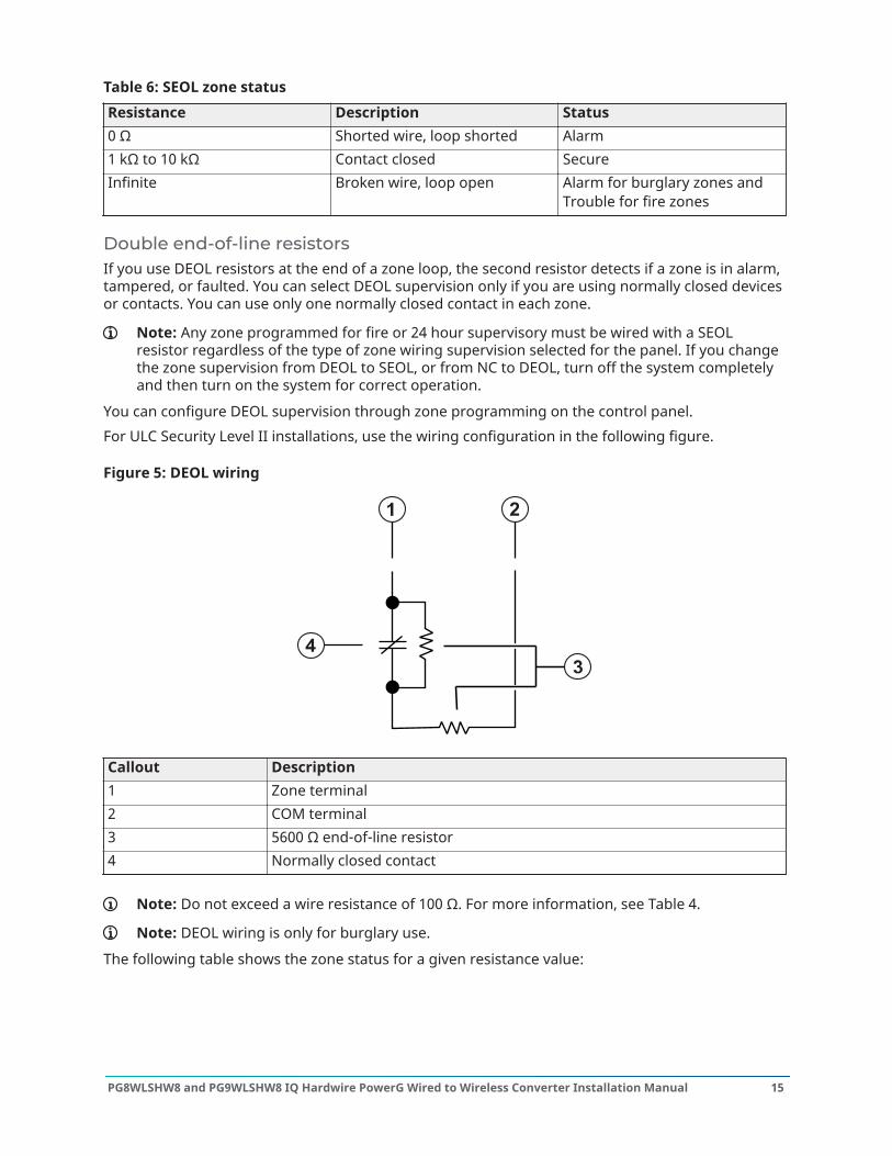
Table 6: SEOL zone statusResistance Description Status0 Ω Shorted wire, loop shorted Alarm1 kΩ to 10 kΩ Contact closed SecureInfinite Broken wire, loop open Alarm for burglary zones and
Trouble for fire zones
Double end-of-line resistorsIf you use DEOL resistors at the end of a zone loop, the second resistor detects if a zone is in alarm,tampered, or faulted. You can select DEOL supervision only if you are using normally closed devicesor contacts. You can use only one normally closed contact in each zone.
Note: Any zone programmed for fire or 24 hour supervisory must be wired with a SEOLresistor regardless of the type of zone wiring supervision selected for the panel. If you changethe zone supervision from DEOL to SEOL, or from NC to DEOL, turn off the system completelyand then turn on the system for correct operation.
You can configure DEOL supervision through zone programming on the control panel.For ULC Security Level II installations, use the wiring configuration in the following figure.
Figure 5: DEOL wiring
Callout Description1 Zone terminal2 COM terminal3 5600 Ω end-of-line resistor4 Normally closed contact
Note: Do not exceed a wire resistance of 100 Ω. For more information, see Table 4.
Note: DEOL wiring is only for burglary use.
The following table shows the zone status for a given resistance value:
15PG8WLSHW8 and PG9WLSHW8 IQ Hardwire PowerG Wired to Wireless Converter Installation Manual
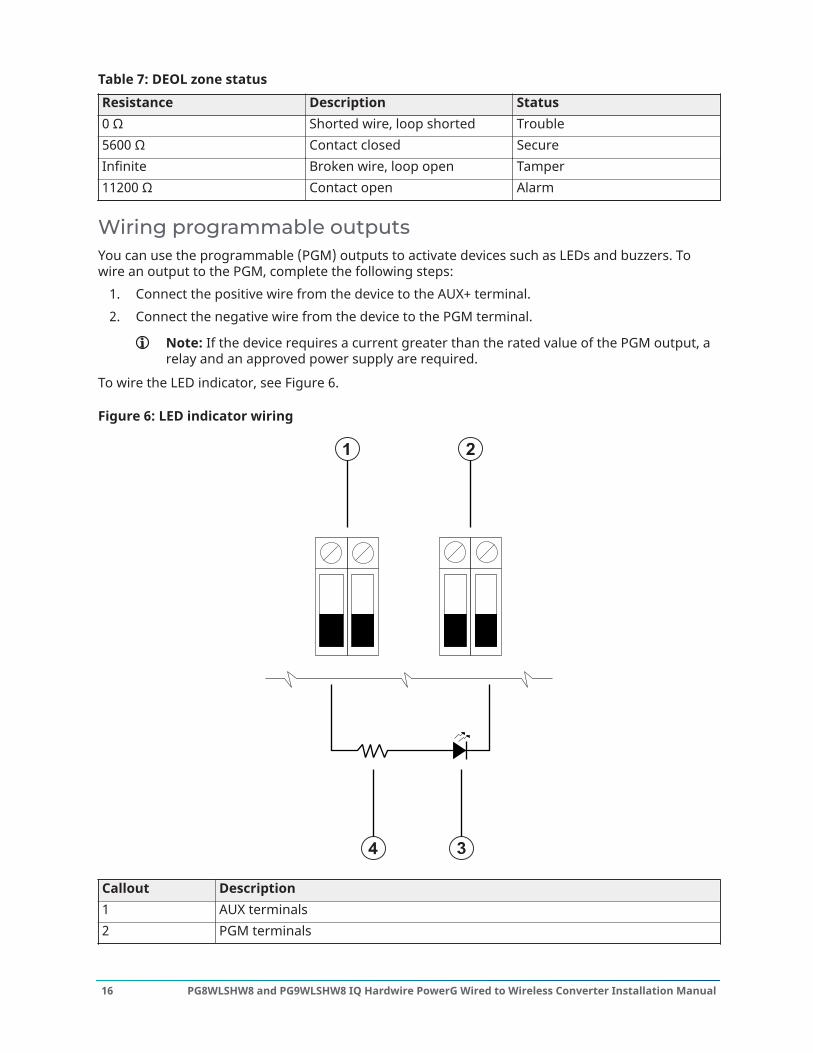
Table 7: DEOL zone statusResistance Description Status0 Ω Shorted wire, loop shorted Trouble5600 Ω Contact closed SecureInfinite Broken wire, loop open Tamper11200 Ω Contact open Alarm
Wiring programmable outputsYou can use the programmable (PGM) outputs to activate devices such as LEDs and buzzers. Towire an output to the PGM, complete the following steps:
1. Connect the positive wire from the device to the AUX+ terminal.2. Connect the negative wire from the device to the PGM terminal.
Note: If the device requires a current greater than the rated value of the PGM output, arelay and an approved power supply are required.
To wire the LED indicator, see Figure 6.
Figure 6: LED indicator wiring
Callout Description1 AUX terminals2 PGM terminals
PG8WLSHW8 and PG9WLSHW8 IQ Hardwire PowerG Wired to Wireless Converter Installation Manual16
Callout Description3 LED indicator4 680 Ω resistor (typical value)
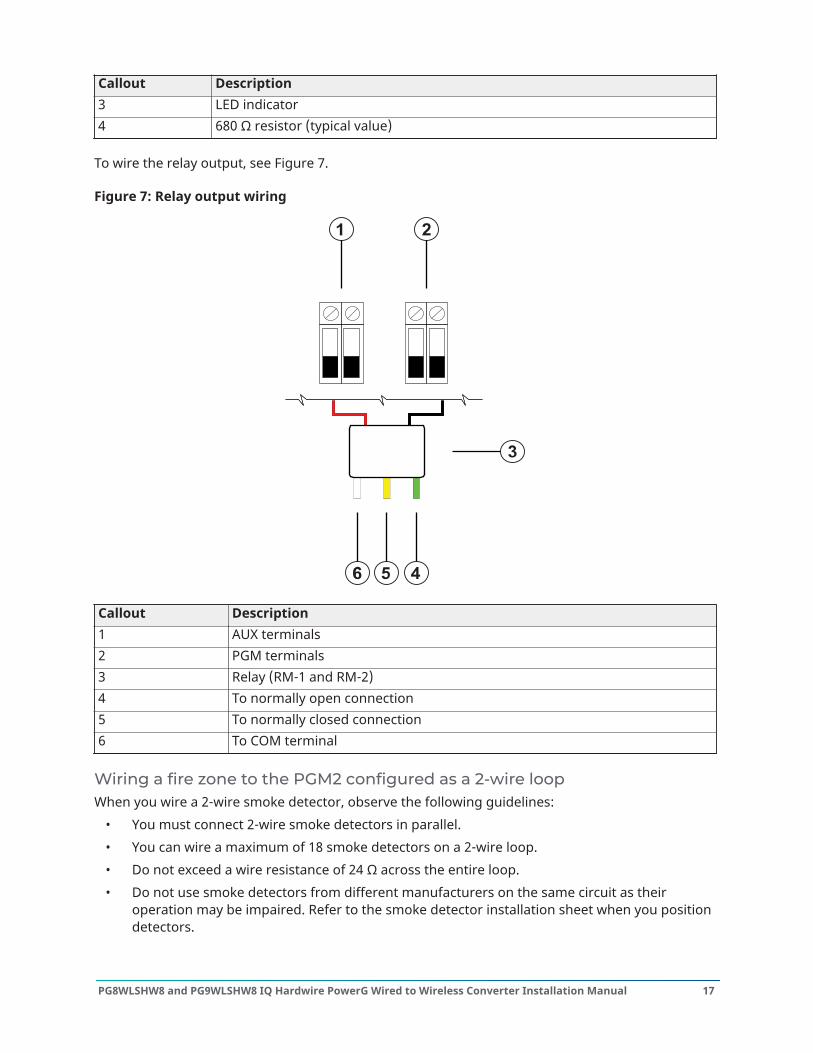
To wire the relay output, see Figure 7.
Figure 7: Relay output wiring
Callout Description1 AUX terminals2 PGM terminals3 Relay (RM-1 and RM-2)4 To normally open connection5 To normally closed connection6 To COM terminal
Wiring a fire zone to the PGM2 configured as a 2-wire loopWhen you wire a 2-wire smoke detector, observe the following guidelines:
• You must connect 2-wire smoke detectors in parallel.• You can wire a maximum of 18 smoke detectors on a 2-wire loop.• Do not exceed a wire resistance of 24 Ω across the entire loop.• Do not use smoke detectors from different manufacturers on the same circuit as their
operation may be impaired. Refer to the smoke detector installation sheet when you positiondetectors.
17PG8WLSHW8 and PG9WLSHW8 IQ Hardwire PowerG Wired to Wireless Converter Installation Manual

• For UL and ULC residential fire applications, use only the AUX2 output to provide power tosmoke and CO detectors.
If you program PGM2 for use with a 2-wire smoke detector, you must wire it according to thefollowing figure:
Figure 8: 2-wire smoke detector wiring
AUX21
PGM3 4-+ 2
+
-
+
-
Callout Description1 2200 Ω end-of-line resistor
The following table lists compatible 2-wire smoke detectors:Table 8: 2-wire smoke detectorsDetector nameFSA-210X FSA-210XLST FSA-210XRST C2WTA-BA (ULC)FSA-210XT FSA-210XR FSA-210XLRST 2W-B (UL)FSA-210XS FSA-210XRT C2W-BA (ULC) 2WT-B (UL)FSA-210XST FSA-210XRS C2WT-BA (ULC) 2WTA-B (UL)
Note: For the DSC FS210 series, X in the detector name represents A for ULC and B for ULlisted models.
Note: If you use System Sensor detectors on a 2-wire loop, do not combine UL and ULCdetectors. For more information, refer to the System Sensor installation manual.
Note: Do not connect accessories, such as a PRM-2W or any other polarity reversal module, to2-wire smoke detectors.
The UL compatibility ID for the FSA-210B series is FS200, and for the System Sensor models is A.
Note: For ULC listed installations, use FSA-210A series detectors or FSA-410A series detectors.
Note: You must calculate and test the current draw.
Table 9: 2-wire smoke detector initiation circuitItem SpecificationClass, supervised, power limited Class B IDC. 2-wire smoke detector interfaceCompatibility identifier PG9WLSHW8-1
PG8WLSHW8 and PG9WLSHW8 IQ Hardwire PowerG Wired to Wireless Converter Installation Manual18
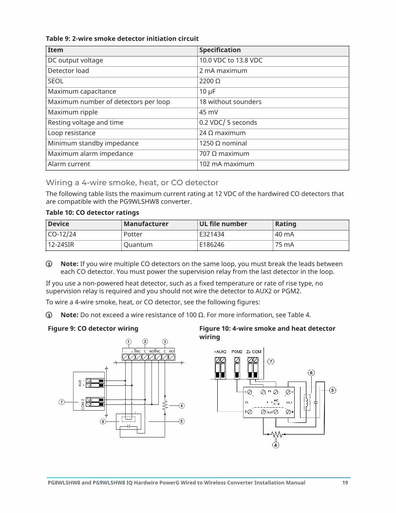
Table 9: 2-wire smoke detector initiation circuitItem SpecificationDC output voltage 10.0 VDC to 13.8 VDCDetector load 2 mA maximumSEOL 2200 ΩMaximum capacitance 10 μFMaximum number of detectors per loop 18 without soundersMaximum ripple 45 mVResting voltage and time 0.2 VDC/ 5 secondsLoop resistance 24 Ω maximumMinimum standby impedance 1250 Ω nominalMaximum alarm impedance 707 Ω maximumAlarm current 102 mA maximum
Wiring a 4-wire smoke, heat, or CO detectorThe following table lists the maximum current rating at 12 VDC of the hardwired CO detectors thatare compatible with the PG9WLSHW8 converter.Table 10: CO detector ratingsDevice Manufacturer UL file number RatingCO-12/24 Potter E321434 40 mA12-24SIR Quantum E186246 75 mA
Note: If you wire multiple CO detectors on the same loop, you must break the leads betweeneach CO detector. You must power the supervision relay from the last detector in the loop.
If you use a non-powered heat detector, such as a fixed temperature or rate of rise type, nosupervision relay is required and you should not wire the detector to AUX2 or PGM2.To wire a 4-wire smoke, heat, or CO detector, see the following figures:
Note: Do not exceed a wire resistance of 100 Ω. For more information, see Table 4.
Figure 9: CO detector wiring
NC NO- + C NC NOC
- +
+
-C
OM
ZAU
X
Figure 10: 4-wire smoke and heat detectorwiring
19PG8WLSHW8 and PG9WLSHW8 IQ Hardwire PowerG Wired to Wireless Converter Installation Manual

Callout Description1 4-wire smoke, heat, or CO detector power terminals2 4-wire smoke, heat, or CO detector alarm terminals3 4-wire smoke, heat, or CO trouble terminals, if provided4 5600 Ω single end-of-line resistor5 100 Ω alarm initiating loop6 RM-1 or RM-2 power loop supervisory relay, 12 VDC, 35 mA.7 Module zone input
Note: You can manually configure PGM2 as a 2-wire smoke loop in panel programming. If youconfigure any zone input as a fire zone, PGM2 is automatically set as a 4-wire smoke detector,and acts as a power reset. You cannot combine 2-wire detectors and 4-wire smoke or heatdetectors at the same time on the converter.
Wiring auxiliary powerYou can use the auxiliary power terminals to power devices such as motion detectors and glassbreak detectors. The AUX1 and AUX2 terminals provide a combined current of 700 mA.
Note: For UL and ULC combination fire and CO and burglary applications, the fire and COinitiating devices, such as smoke detectors, heat detectors, and CO detectors, must bepowered from a separate output (AUX2) than the burglary initiating devices (AUX1).
Note: For UL and ULC installations that require 24-hour backup capacity, the maximum AUXpower load cannot exceed a current of 180 mA when using a 7 Ah battery.
Wiring the bell outputYou can use the BELL terminals to power a bell, siren, or other device which requires a steadyoutput voltage when the system is in alarm. The panel provides a current of up to 700 mA.
Note: A 1 kΩ resistor is required across the BELL+ and BELL- terminals, or the system detects atrouble condition.
Installing the batteryTo install the 12 VDC/ 7 Ah battery in the enclosure, complete the following steps:
Note: The battery is sold separately.
1. Place the battery on the two plasic supports on the bottom of the enclosure. For moreinformation, see Figure 11.
2. Clip the battery in place.3. Optional: The battery can also be secured in place using a battery strap. To secure the
battery using the battery strap, complete the following steps:
Note: The battery strap is sold separately.
a. Place the battery on the two plasic supports on the bottom of the enclosure.b. Insert the battery strap through one of the slots.c. Wrap the strap around the front of the battery.d. Insert the strap through the second slot.
PG8WLSHW8 and PG9WLSHW8 IQ Hardwire PowerG Wired to Wireless Converter Installation Manual20
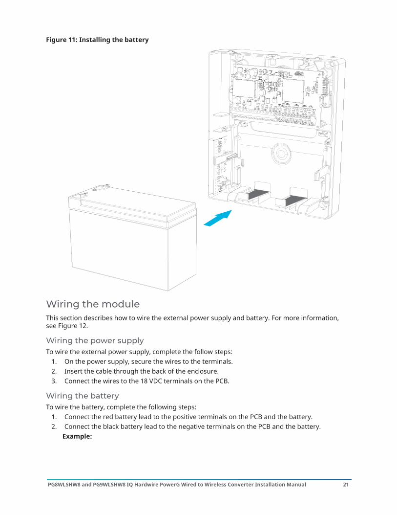
Figure 11: Installing the battery
Wiring the moduleThis section describes how to wire the external power supply and battery. For more information,see Figure 12.
Wiring the power supplyTo wire the external power supply, complete the follow steps:
1. On the power supply, secure the wires to the terminals.2. Insert the cable through the back of the enclosure.3. Connect the wires to the 18 VDC terminals on the PCB.
Wiring the batteryTo wire the battery, complete the following steps:
1. Connect the red battery lead to the positive terminals on the PCB and the battery.2. Connect the black battery lead to the negative terminals on the PCB and the battery.
Example:
21PG8WLSHW8 and PG9WLSHW8 IQ Hardwire PowerG Wired to Wireless Converter Installation Manual
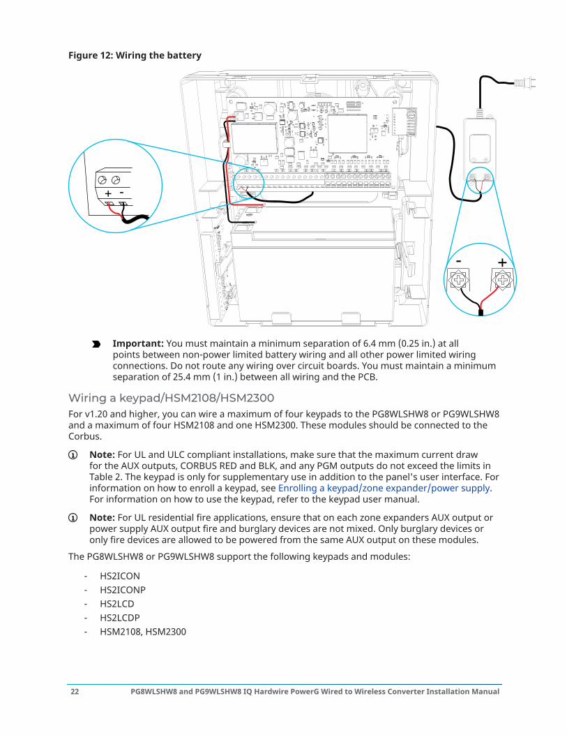
Figure 12: Wiring the battery
+-
- +
-+
Important: You must maintain a minimum separation of 6.4 mm (0.25 in.) at allpoints between non-power limited battery wiring and all other power limited wiringconnections. Do not route any wiring over circuit boards. You must maintain a minimumseparation of 25.4 mm (1 in.) between all wiring and the PCB.
Wiring a keypad/HSM2108/HSM2300For v1.20 and higher, you can wire a maximum of four keypads to the PG8WLSHW8 or PG9WLSHW8and a maximum of four HSM2108 and one HSM2300. These modules should be connected to theCorbus.
Note: For UL and ULC compliant installations, make sure that the maximum current drawfor the AUX outputs, CORBUS RED and BLK, and any PGM outputs do not exceed the limits inTable 2. The keypad is only for supplementary use in addition to the panel's user interface. Forinformation on how to enroll a keypad, see Enrolling a keypad/zone expander/power supply.For information on how to use the keypad, refer to the keypad user manual.
Note: For UL residential fire applications, ensure that on each zone expanders AUX output orpower supply AUX output fire and burglary devices are not mixed. Only burglary devices oronly fire devices are allowed to be powered from the same AUX output on these modules.
The PG8WLSHW8 or PG9WLSHW8 support the following keypads and modules:
- HS2ICON- HS2ICONP- HS2LCD- HS2LCDP- HSM2108, HSM2300
PG8WLSHW8 and PG9WLSHW8 IQ Hardwire PowerG Wired to Wireless Converter Installation Manual22
Note: Starting with v1.20 Proximity tags are supported on the PG8WLSHW8 or PG9WLSHW8.
You can use the keypad to perform the following operations:
- To arm and disarm the system.- To view zone status.- To view partition status.- To use the keypad function keys.- The * menus support *1 Bypass, *2 Troubles, *3 Alarm Memory, *4 Chime, *6 User
Functions (keypad buzzer, contrast and brightness only), *7 Command Outputs 1-4, *9 NoEntry Arm, and *0 Quick Arm/Quick Exit.
Note: In v1.20 this is supported on up to 4x HSM2108 and 1 x HS2300.
For more information on how to install the keypad and Corbus modules, refer to the keypad's ormodules' installation manual.
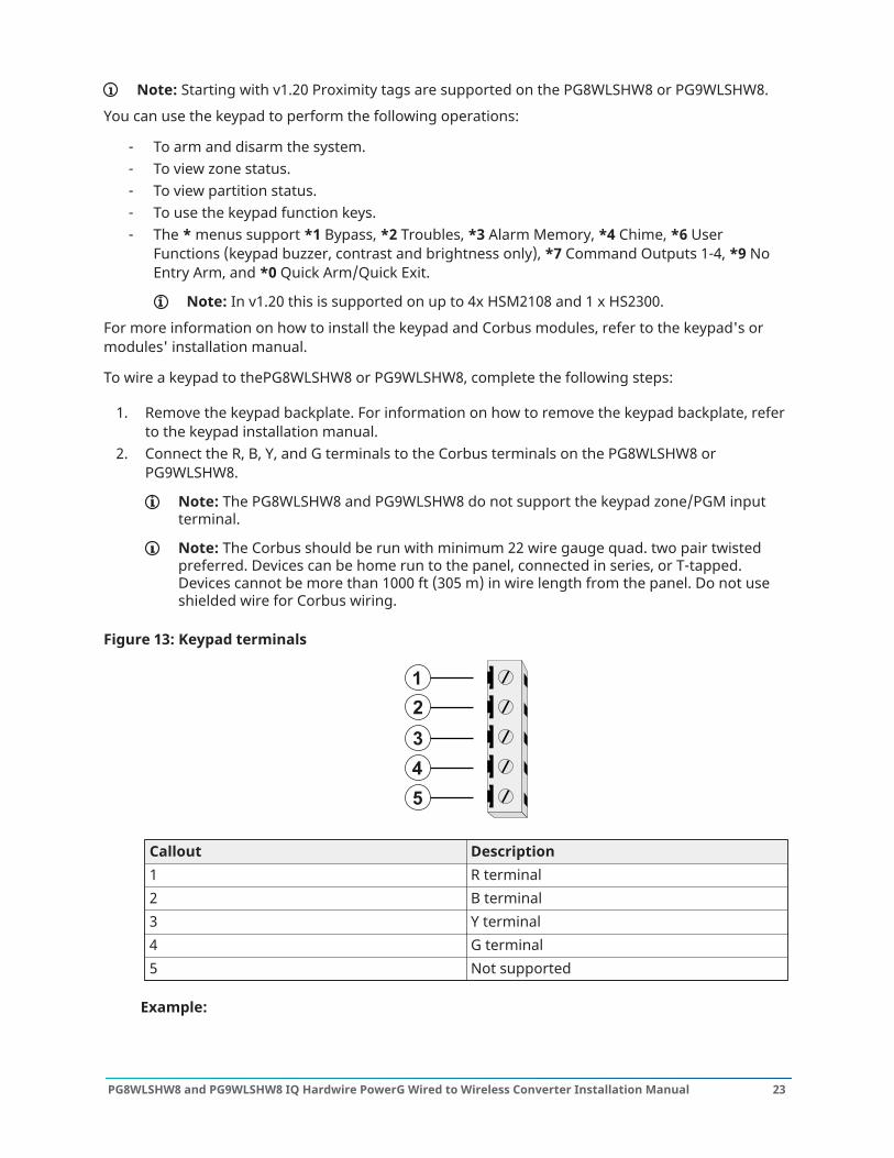
To wire a keypad to thePG8WLSHW8 or PG9WLSHW8, complete the following steps:
1. Remove the keypad backplate. For information on how to remove the keypad backplate, referto the keypad installation manual.
2. Connect the R, B, Y, and G terminals to the Corbus terminals on the PG8WLSHW8 orPG9WLSHW8.
Note: The PG8WLSHW8 and PG9WLSHW8 do not support the keypad zone/PGM inputterminal.
Note: The Corbus should be run with minimum 22 wire gauge quad. two pair twistedpreferred. Devices can be home run to the panel, connected in series, or T-tapped.Devices cannot be more than 1000 ft (305 m) in wire length from the panel. Do not useshielded wire for Corbus wiring.
Figure 13: Keypad terminals
Callout Description1 R terminal2 B terminal3 Y terminal4 G terminal5 Not supported
Example:
23PG8WLSHW8 and PG9WLSHW8 IQ Hardwire PowerG Wired to Wireless Converter Installation Manual

When you install multiple keypads and modules, wire keypads using the same partition on thesame module to improve keypad performance. Keypads on partition one should be wired intomodule one, and keypads on partition two should be wired into module two.
Silencing fire alarm or CO alarm bellsThis section describes how to silence Fire alarms or CO AlarmsFire alarms or CO Alarms can be silenced by entering a valid access code. The message "Fire Alarm/Bells Silenced" or "CO Alarm/Bells Silenced" will be displayed on the LCD keypad connected to thecorbus. The message will not be cleared until all the fire zones zones have been restored on system.
PG8WLSHW8 and PG9WLSHW8 IQ Hardwire PowerG Wired to Wireless Converter Installation Manual24
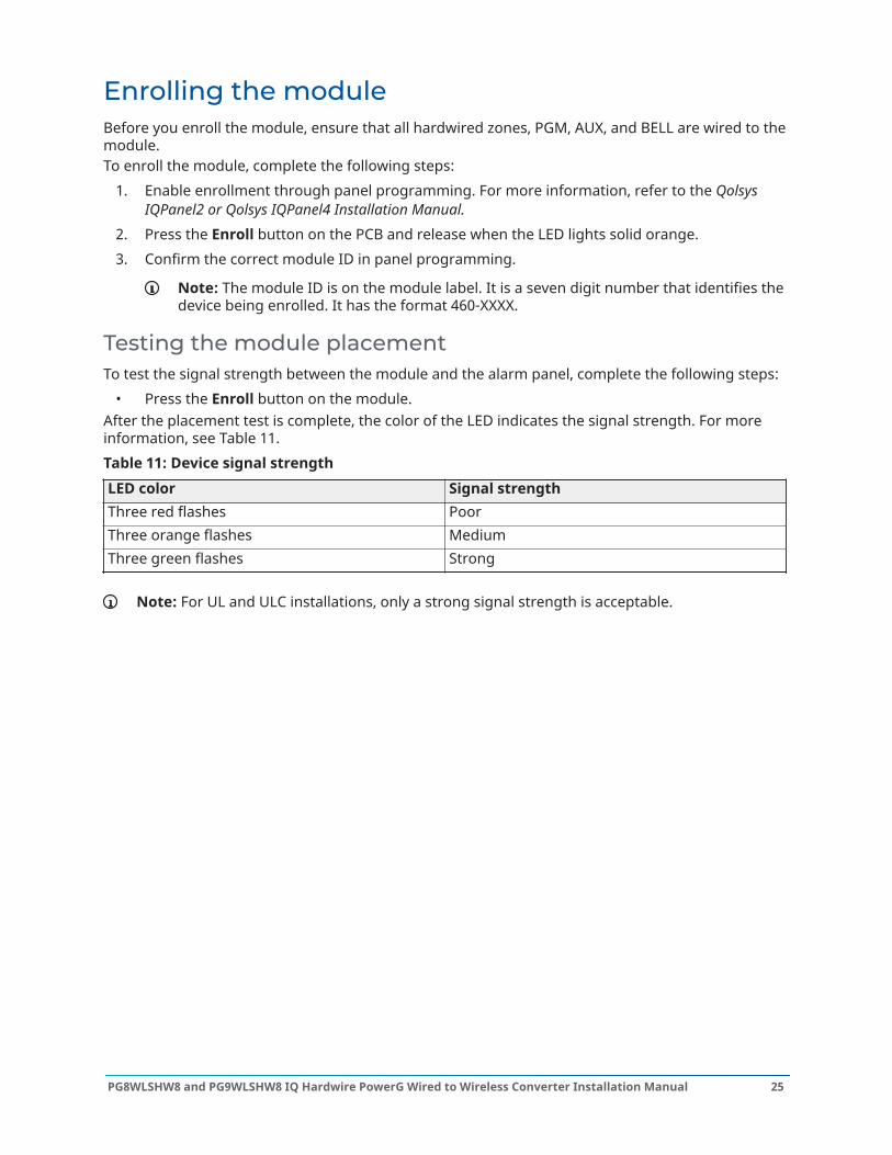
Enrolling the moduleBefore you enroll the module, ensure that all hardwired zones, PGM, AUX, and BELL are wired to themodule.To enroll the module, complete the following steps:
1. Enable enrollment through panel programming. For more information, refer to the QolsysIQPanel2 or Qolsys IQPanel4 Installation Manual.
2. Press the Enroll button on the PCB and release when the LED lights solid orange.3. Confirm the correct module ID in panel programming.
Note: The module ID is on the module label. It is a seven digit number that identifies thedevice being enrolled. It has the format 460-XXXX.
Testing the module placementTo test the signal strength between the module and the alarm panel, complete the following steps:
• Press the Enroll button on the module.After the placement test is complete, the color of the LED indicates the signal strength. For moreinformation, see Table 11.Table 11: Device signal strengthLED color Signal strengthThree red flashes PoorThree orange flashes MediumThree green flashes Strong
Note: For UL and ULC installations, only a strong signal strength is acceptable.
25PG8WLSHW8 and PG9WLSHW8 IQ Hardwire PowerG Wired to Wireless Converter Installation Manual
Enrolling wired zones automaticallyWhen you successfully enroll the module to the control panel, eight hardwired zones are added tothe control panel. The zones display on the control panel with the same ID as the module and zonelabel as the corresponding hardwired input. Enable and configure each zone input and PGM usingthe zone configuration options on the control panel.
PG8WLSHW8 and PG9WLSHW8 IQ Hardwire PowerG Wired to Wireless Converter Installation Manual26

Enrolling a keypad/zone expander/power supplyTo enroll a keypad or device on to the module, complete the following steps:
1. Select Settings > Advanced Settings > Installation > Devices > Security Sensors.a. To automatically enroll all keypads and modules that are correctly wired to the module,
select Auto Learn.b. To manually enroll a keypad that is correctly wired to the module, select Add Sensor.
Enter the module serial number, 460-XXXX, then select Corbus from the HardwiredInput drop-down menu and enter the keypad or module serial number.
Note: You must confirm and accept the keypad enrollment on the IQ Panel 2 or IQPanel4.
27PG8WLSHW8 and PG9WLSHW8 IQ Hardwire PowerG Wired to Wireless Converter Installation Manual
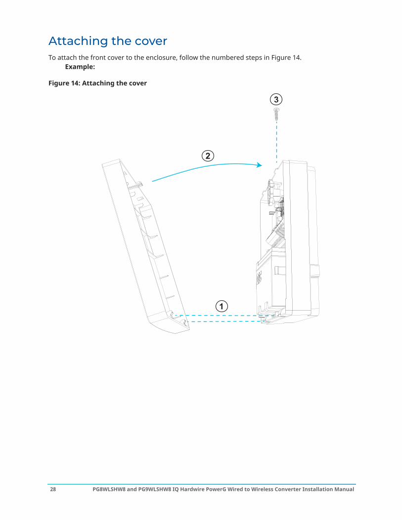
Attaching the coverTo attach the front cover to the enclosure, follow the numbered steps in Figure 14.
Example:
Figure 14: Attaching the cover
PG8WLSHW8 and PG9WLSHW8 IQ Hardwire PowerG Wired to Wireless Converter Installation Manual28
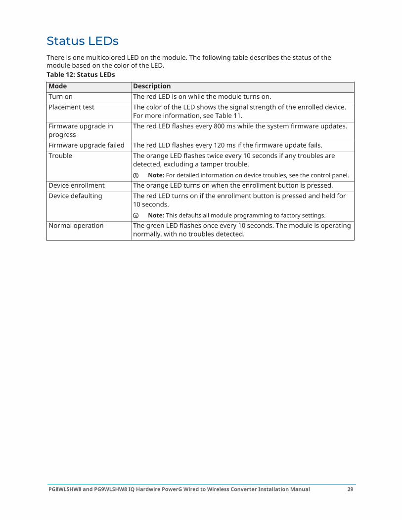
Status LEDsThere is one multicolored LED on the module. The following table describes the status of themodule based on the color of the LED.Table 12: Status LEDsMode DescriptionTurn on The red LED is on while the module turns on.Placement test The color of the LED shows the signal strength of the enrolled device.
For more information, see Table 11.Firmware upgrade inprogress
The red LED flashes every 800 ms while the system firmware updates.
Firmware upgrade failed The red LED flashes every 120 ms if the firmware update fails.Trouble The orange LED flashes twice every 10 seconds if any troubles are
detected, excluding a tamper trouble.Note: For detailed information on device troubles, see the control panel.
Device enrollment The orange LED turns on when the enrollment button is pressed.Device defaulting The red LED turns on if the enrollment button is pressed and held for
10 seconds.Note: This defaults all module programming to factory settings.
Normal operation The green LED flashes once every 10 seconds. The module is operatingnormally, with no troubles detected.
29PG8WLSHW8 and PG9WLSHW8 IQ Hardwire PowerG Wired to Wireless Converter Installation Manual
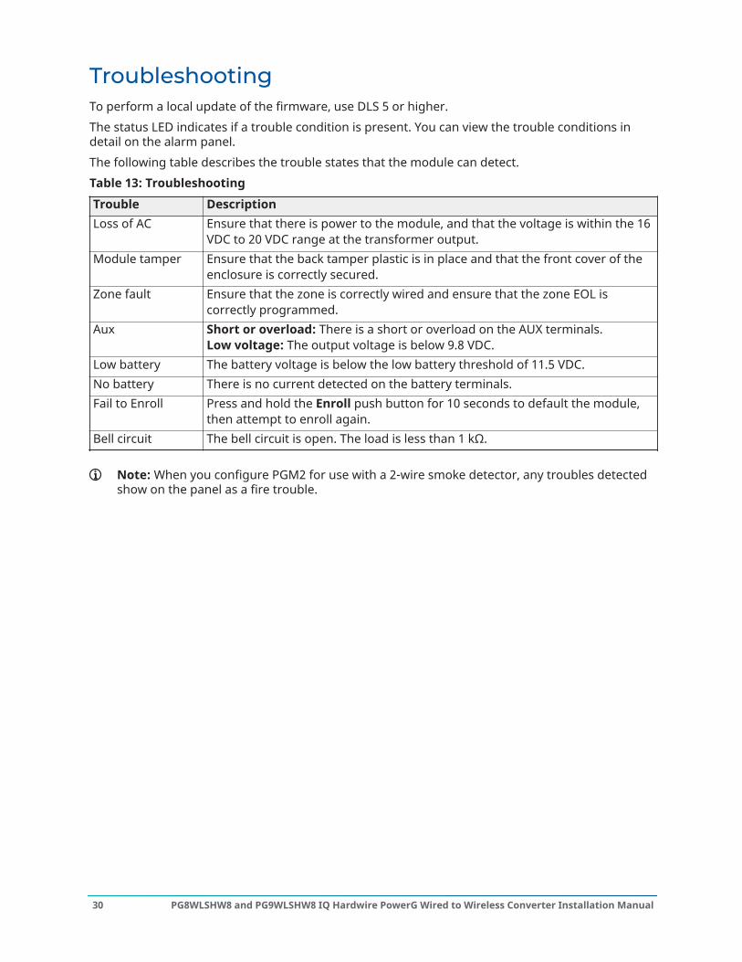
TroubleshootingTo perform a local update of the firmware, use DLS 5 or higher.The status LED indicates if a trouble condition is present. You can view the trouble conditions indetail on the alarm panel.The following table describes the trouble states that the module can detect.Table 13: TroubleshootingTrouble DescriptionLoss of AC Ensure that there is power to the module, and that the voltage is within the 16
VDC to 20 VDC range at the transformer output.Module tamper Ensure that the back tamper plastic is in place and that the front cover of the
enclosure is correctly secured.Zone fault Ensure that the zone is correctly wired and ensure that the zone EOL is
correctly programmed.Aux Short or overload: There is a short or overload on the AUX terminals.
Low voltage: The output voltage is below 9.8 VDC.Low battery The battery voltage is below the low battery threshold of 11.5 VDC.No battery There is no current detected on the battery terminals.Fail to Enroll Press and hold the Enroll push button for 10 seconds to default the module,
then attempt to enroll again.Bell circuit The bell circuit is open. The load is less than 1 kΩ.
Note: When you configure PGM2 for use with a 2-wire smoke detector, any troubles detectedshow on the panel as a fire trouble.
PG8WLSHW8 and PG9WLSHW8 IQ Hardwire PowerG Wired to Wireless Converter Installation Manual30
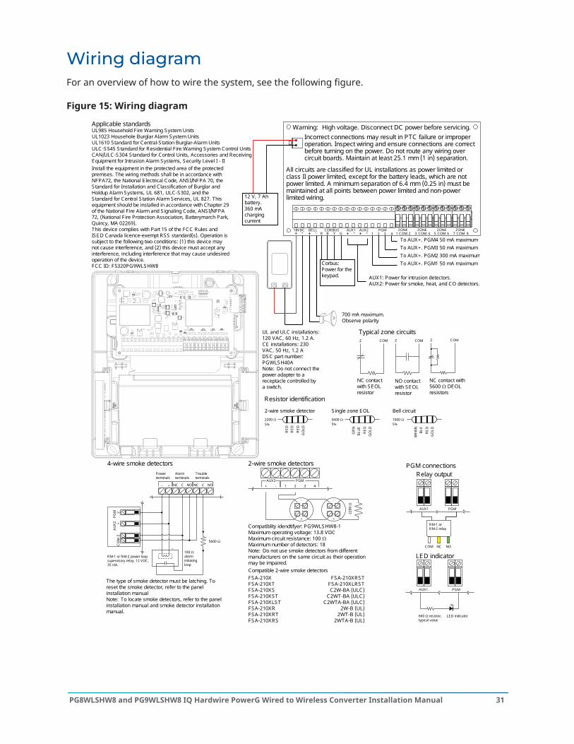
Wiring diagramFor an overview of how to wire the system, see the following figure.
Figure 15: Wiring diagram
Applicable standardsUL985 Household Fire Warning System UnitsUL1023 Househole Burglar Alarm System UnitsUL1610 Standard for Central-Station Burglar-Alarm UnitsULC-S545 Standard for Residential Fire Warning System Control UnitsCAN/ULC-S304 Standard for Control Units, Accessories and Receiving Equipment for Intrusion Alarm Systems, Security Level I - IIInstall the equipment in the protected area of the protected premises. The wiring methods shall be in accordance with NFPA72, the National E lectrical Code, ANSI/NFPA 70, the Standard for Installation and Classification of Burglar and Holdup Alarm Systems, UL 681, ULC-S302, and the Standard for Central Station Alarm Services, UL 827. This equipment should be installed in accordance with Chapter 29 of the National Fire Alarm and S ignaling Code, ANSI/NFPA 72, (National Fire Protection Association, Batterymarch Park, Quincy, MA 02269).This device complies with Part 15 of the FCC Rules and ISED Canada licence-exempt RSS standard(s). Operation is subject to the following two conditions: (1) this device may not cause interference, and (2) this device must accept any interference, including interference that may cause undesired operation of the device. FCC ID: F5320PG9WLSHW8
PGM connections
LED indicator
AUX1 PGM
LED indicator660 Ω resistor,typical value
Relay output
AUX1 PGM
COM NC NO
RM-1 or RM-2 relay
Typical zone circuitsZ COM Z COM Z COM
NC contact with SEOL resistor
NO contact with SEOL resistor
NC contact with 5600 Ω DEOL resistors
1 8765432 COMCOMCOMCOM4PGM
1 2 3AUX2AUX1
+ + --R B Y GCORBUS ZONE ZONEZONEZONEBELL
+ -+ -18VDC
To AUX+. PGM4 50 mA maximum
To AUX+. PGM1 50 mA maximumTo AUX+. PGM2 300 mA maximumTo AUX+. PGM3 50 mA maximum
700 mA maximum. Observe polarity
12 V, 7 Ah battery.360 mA charging current
UL and ULC installations: 120 VAC, 60 Hz, 1.2 A.CE installations: 230 VAC, 50 Hz, 1.2 ADSC part number: PGWLSH40ANote: Do not connect the power adapter to a receptacle controlled by a switch.
Warning: High voltage. Disconnect DC power before servicing.Incorrect connections may result in PTC failure or improper operation. Inspect wiring and ensure connections are correct before turning on the power. Do not route any wiring over circuit boards. Maintain at least 25.1 mm (1 in) separation.
All circuits are classified for UL installations as power limited or class II power limited, except for the battery leads, which are not power limited. A minimum separation of 6.4 mm (0.25 in) must be maintained at all points between power limited and non-power limited wiring.
Resistor identification
2-wire smoke detector
RED
RED
RED
GO
LD
2200 Ω5%
Bell circuit
RED
GO
LDBLK
BRW
N
5%1000 Ω
Single zone EOL
RED
GO
LD
GR
NBL
UE
5%5600 Ω
Corbus: Power for the keypad.
4-wire smoke detectors
NC NO- + C NC NOC
- +
+
CO
MZ
AUX2
PGM 2
The type of smoke detector must be latching. To reset the smoke detector, refer to the panel installation manualNote: To locate smoke detectors, refer to the panel installation manual and smoke detector installation manual.
5600 Ω
100 Ω alarm initiating loop
RM-1 or RM-2 power loop supervisory relay, 12 VDC, 35 mA.
Power terminals
Alarm terminals
Trouble terminals
AUX21
PGM3 4-+ 2
+
-
+
-
2-wire smoke detectors
Compatiblity idendtifyer: PG9WLSHW8-1Maximum operating voltage: 13.8 VDCMaximum circuit resistance: 100 ΩMaximum number of detectors: 18Note: Do not use smoke detectors from different manufacturers on the same circuit as their operation may be impaired.
2200
Ω
FSA-210X FSA-210XRSTFSA-210XT FSA-210XLRSTFSA-210XS C2W-BA (ULC)FSA-210XST C2WT-BA (ULC)FSA-210XLST C2WTA-BA (ULC)FSA-210XR 2W-B (UL)FSA-210XRT 2WT-B (UL)FSA-210XRS 2WTA-B (UL)
Compatible 2-wire smoke detectors
AUX1: Power for intrusion detectors.AUX2: Power for smoke, heat, and CO detectors.
31PG8WLSHW8 and PG9WLSHW8 IQ Hardwire PowerG Wired to Wireless Converter Installation Manual

FCC and ISED Canada InformationThis information applies to model PG9WLSHW8.
Modification statementTyco Safety Products Canada Ltd. has not approved any changes or modifications to this device bythe user. Any changes or modifications could void the user’s authority to operate the equipment.Tyco Safety Products Canada Ltd. n’approuve aucune modification apportée à l’appareil parl’utilisateur, quelle qu’en soit la nature. Tout changement ou modification peuvent annuler le droitd’utilisation de l’appareil par l’utilisateur.
Interference statementThis device complies with Part 15 of the FCC Rules and ISED Canada licence-exempt RSSstandard(s). Operation is subject to the following two conditions: (1) this device may not causeinterference, and (2) this device must accept any interference, including interference that maycause undesired operation of the device.Le présent appareil est conforme aux CNR d'ISED Canada applicables aux appareils radio exemptsde licence. L'exploitation est autorisée aux deux conditions suivantes : (1) l'appareil ne doit pasproduire de brouillage, et (2) l'utilisateur de l'appareil doit accepter tout brouillage radioélectriquesubi, même si le brouillage est susceptible d'en compromettre le fonctionnement.
Wireless noticeThis equipment complies with FCC and IC radiation exposure limits set forth for an uncontrolledenvironment. The antenna should be installed and operated with minimum distance of 20 cmbetween the radiator and your body. This transmitter must not be co-located or operating inconjunction with any other antenna or transmitter.Cet appareil est conforme aux limites d'exposition aux rayonnements de la IC pour unenvironnement non contrôlé. L'antenne doit être installé de façon à garder une distance minimalede 20 centimètres entre la source de rayonnements et votre corps. L'émetteur ne doit pas êtrecolocalisé ni fonctionner conjointement avec à autre antenne ou autre émetteur.
PG8WLSHW8 and PG9WLSHW8 IQ Hardwire PowerG Wired to Wireless Converter Installation Manual32

FCC class B digital device noticeThis equipment has been tested and found to comply with the limits for a Class B digital device,pursuant to part 15 of the FCC Rules. These limits are designed to provide reasonable protectionagainst harmful interference in a residential installation. This equipment generates uses and canradiate radio frequency energy and, if not installed and used in accordance with the instructions,may cause harmful interference to radio communications. However, there is no guarantee thatinterference will not occur in a particular installation. If this equipment does cause harmfulinterference to radio or television reception, which can be determined by turning the equipmentoff and on, the user is encouraged to try to correct the interference by one or more of the followingmeasures:
• Reorient or relocate the receiving antenna.• Increase the separation between the equipment and receiver.• Connect the equipment into an outlet on a circuit different from that to which the receiver is
connected.• Consult the dealer or an experienced radio/TV technician for help.
This Class B digital apparatus complies with Canadian ICES-003.Cet appareil numérique de la classe B est conforme à la norme NMB-003du Canada.
WARNING: To satisfy FCC RF exposure requirements for transmitting devices, a separationdistance of 20cm or more must be maintained between the antenna of this device and personsduring device operation.
33PG8WLSHW8 and PG9WLSHW8 IQ Hardwire PowerG Wired to Wireless Converter Installation Manual

UL and ULC notesThe model PG9WLSHW8 has been listed by UL and ULC for commercial burglary and residentialfire/burglary applications in accordance with the requirements in the Standards UL1610/UL1023/UL985 and ULC-S304/ULC-S545. For UL/ULC installations, use this device only in conjunction withcompatible wireless receivers/control panels combination, model Qolsys IQPanel2 and IQPanel4.Test the system weekly. Replace the standby battery every three to five years.
UL commercial and residential installation requirements andconsiderations
UL commercial, UL household, and ULC security level I and IIburglar alarm unit
• Power supply model SOY-1800222-NA (PGWLSHW40A) or HS40WPSNA or HS40WPSA shall beemployed.
• One optional UL or ULC listed audible device rated to operate over the voltage range of 11.3VDC to 12.5 VDC and rated 85 dB minimum.
• One compatible Qolsys IQPanel2 with PowerG modem card.• All input zones shall be programmed as end of line supervised. For ULC Level II use DEOL
supervision.• Burglary initiating devices rated to operate over the voltage range of 11.3 VDC to 12.5 VDC.• All intrusion zones shall be programmed as audible.• The battery shall be used to provide a minimum back up power of four hours as per specific
application requirements
UL and ULC household fire warning system• Power supply model SOY-1800222-NA (PGWLSHW40A) or HS40WPSNA or HS40WPSA shall be
employed.• 24 hour standby shall be provided.• At least one UL or ULC listed 4-wire latching type smoke detector rated to operate over the
voltage range 11.3 VDC to 12.5 VDC. A maximum smoke detector alarm load of 102 mA maybe employed on the 2-wire smoke detector circuit.
• One DSC model RM-1 or RM-2 end of line supervision relay module.• One optional UL or ULC listed audible device, rated to operate over the voltage range 11.3
VDC to 12.5 VDC, with a maximum current rating of 700 mA and rated 85 dB minimumas required for this application. The required bell cutoff time shall be a minimum of fourminutes for UL and five minutes for ULC. The local audible devices shall be programmed tosound in a Temporal 3 pattern.
• Model EOLR-2, for 4-wire smoke detectors, heat detectors, and CO detectors, and EOLR-3, for2-wire smoke interface, end of line resistors shall be used.
• For UL and ULC household fire warning systems, the fire alarm and CO detection devices shallnot be powered from the same AUX output as burglary alarm initiating devices.
PG8WLSHW8 and PG9WLSHW8 IQ Hardwire PowerG Wired to Wireless Converter Installation Manual34

European CE Compliance and CERTALARMCertificationThis information applies to model PG8WLSHW8.According to EN50131-1,this equipment can be applied in installed systems up to and includingSecurity Grade 2, Environmental Class II.UK: The PG8WLSHW8 is suitable for use in systems installed to conform to PD6662:2017 at Grade 2and environmental class II. BS8243:2010 + A1:2014.The PowerG peripheral devices have two-way communication functionality, providing additionalbenefits as described in the technical brochure. This functionality has not been tested to complywith the respective technical requirements and should therefore be considered outside the scopeof the product’s certification.The Model PG8WLSHW8 Wired to Wireless Converter has been certified by Telefication accordingto EN50131-1:2006+ A1:2009, EN50131-3:2009, EN50131-5-3:2017, and EN50131-6:2017 Type A forGrade2, Class II.
Simplified EU declaration of conformityHereby, Tyco Safety Products Canada Ltd declares that the radio equipment type is in compliancewith Directive 2014/53/EU. The full text of the EU declaration of conformity is available at thefollowing internetaddress: www.dsc.com868 MHz model: http://dsc.com/pdf/2001001
Frequency band (MHz) Maximum power (dBm/ mW)
868.0 to 868.6 12/ 15
868.7 to 869.2 12/ 15
European single point of contact: Tyco Safety Products, Voltaweg 20,6101 XK Echt, Netherlands.
35PG8WLSHW8 and PG9WLSHW8 IQ Hardwire PowerG Wired to Wireless Converter Installation Manual

EULAIMPORTANT - READ CAREFULLYDSC Software purchased with or without Products and Components is copyrighted and ispurchased under the following license terms:
• This End- User License Agreement (“EULA”) is a legal agreement between You (the company,individual or entity who acquired the Software and any related Hardware) and Digital SecurityControls, a division of Tyco Safety Products Canada Ltd. (“DSC”), the manufacturer of theintegrated security systems and the developer of the software and any related products orcomponents (“HARDWARE”) which You acquired.
• If the DSC software product (“SOFTWARE PRODUCT” or “SOFTWARE”) is intended to beaccompanied by HARDWARE, and is NOT accompanied by new HARDWARE, You may notuse, copy or install the SOFTWARE PRODUCT. The SOFTWARE PRODUCT includes computersoftware, and may include associated media, printed materials, and “online” or electronicdocumentation.
• Any software provided along with the SOFTWARE PRODUCT that is associated with a separateend- user license agreement is licensed to You under the terms of that license agreement.
• By installing, copying, downloading, storing, accessing or otherwise using the SOFTWAREPRODUCT, You agree unconditionally to be bound by the terms of this EULA, even if this EULAis deemed to be a modification of any previous arrangement or contract. If You do not agreeto the terms of this EULA, DSC is unwilling to license the SOFTWARE PRODUCT to You, andYou have no right to use it.
SOFTWARE PRODUCT LICENSEThe SOFTWARE PRODUCT is protected by copyright laws and international copyright treaties, aswell as other intellectual property laws and treaties. The SOFTWARE PRODUCT is licensed, not sold.1. GRANT OF LICENSE This EULA grants You the following rights:
• Software Installation and Use - For each license You acquire, You may have only one copy ofthe SOFTWARE PRODUCT installed.
• Storage/Network Use - The SOFTWARE PRODUCT may not be installed, accessed, displayed,run, shared or used concurrently on or from different computers, including a workstation,terminal or other digital electronic device (“Device”). In other words, if You have severalworkstations, You will have to acquire a license for each workstation where the SOFTWAREwill be used.
• Backup Copy - You may make back-up copies of the SOFTWARE PRODUCT, but You may onlyhave one copy per license installed at any given time. You may use the back-up copy solelyfor archival purposes. Except as expressly provided in this EULA, You may not otherwisemake copies of the SOFTWARE PRODUCT, including the printed materials accompanying theSOFTWARE.
2. DESCRIPTION OF OTHER RIGHTS AND LIMITATIONS• Limitations on Reverse Engineering, Decompilation and Disassembly - You may not reverse
engineer, decompile, or disassemble the SOFTWARE PRODUCT, except and only to the extentthat such activity is expressly permitted by applicable law notwithstanding this limitation. Youmay not make any changes or modifications to the Software, without the written permissionof an officer of DSC. You may not remove any proprietary notices, marks or labels from theSoftware Product. You shall institute reasonable measures to ensure compliance with theterms and conditions of this EULA.
PG8WLSHW8 and PG9WLSHW8 IQ Hardwire PowerG Wired to Wireless Converter Installation Manual36

• Separation of Components - The SOFTWARE PRODUCT is licensed as a single product. Itscomponent parts may not be separated for use on more than one HARDWARE unit.
• Single INTEGRATED PRODUCT - If You acquired this SOFTWARE with HARDWARE, then theSOFTWARE PRODUCT is licensed with the HARDWARE as a single integrated product. In thiscase, the SOFTWARE PRODUCT may only be used with the HARDWARE as set forth in thisEULA.
• Rental - You may not rent, lease or lend the SOFTWARE PRODUCT. You may not make itavailable to others or post it on a server or web site.
• Software Product Transfer - You may transfer all of Your rights under this EULA only as part ofa permanent sale or transfer of the HARDWARE, provided You retain no copies, You transferall of the SOFTWARE PRODUCT (including all component parts, the media and printedmaterials, any upgrades and this EULA), and provided the recipient agrees to the terms ofthis EULA. If the SOFTWARE PRODUCT is an upgrade, any transfer must also include all priorversions of the SOFTWARE PRODUCT.
• Termination - Without prejudice to any other rights, DSC may terminate this EULA if You failto comply with the terms and conditions of this EULA. In such event, You must destroy allcopies of the SOFTWARE PRODUCT and all of its component parts.
• Trademarks - This EULA does not grant You any rights in connection with any trademarks orservice marks of DSC or its suppliers.
3. COPYRIGHT - All title and intellectual property rights in and to the SOFTWARE PRODUCT(including but not limited to any images, photographs, and text incorporated into the SOFTWAREPRODUCT), the accompanying printed materials, and any copies of the SOFTWARE PRODUCT,are owned by DSC or its suppliers. You may not copy the printed materials accompanying theSOFTWARE PRODUCT. All title and intellectual property rights in and to the content which may beaccessed through use of the SOFTWARE PRODUCT are the property of the respective content ownerand may be protected by applicable copyright or other intellectual property laws and treaties. ThisEULA grants You no rights to use such content. All rights not expressly granted under this EULA arereserved by DSC and its suppliers.4. EXPORT RESTRICTIONS - You agree that You will not export or re-export the SOFTWAREPRODUCT to any country, person, or entity subject to Canadian export restrictions.5. CHOICE OF LAW - This Software License Agreement is governed by the laws of the Province ofOntario, Canada.6. ARBITRATION - All disputes arising in connection with this Agreement shall be determined byfinal and binding arbitration in accordance with the Arbitration Act, and the parties agree to bebound by the arbitrator’s decision. The place of arbitration shall be Toronto, Canada, and theinstallation manual of the arbitration shall be English.7. LIMITED WARRANTY
• NO WARRANTY - DSC PROVIDES THE SOFTWARE “AS IS” WITHOUT WARRANTY. DSC DOESNOT WARRANT THAT THE SOFTWARE WILL MEET YOUR REQUIREMENTS OR THAT OPERATIONOF THE SOFTWARE WILL BE UNINTERRUPTED OR ERROR-FREE.
• CHANGES IN OPERATING ENVIRONMENT - DSC shall not be responsible for problemscaused by changes in the operating characteristics of the HARDWARE, or for problems in theinteraction of the SOFTWARE PRODUCT with non-DSC-SOFTWARE or HARDWARE PRODUCTS.
37PG8WLSHW8 and PG9WLSHW8 IQ Hardwire PowerG Wired to Wireless Converter Installation Manual
• LIMITATION OF LIABILITY; WARRANTY REFLECTS ALLOCATION OF RISK - IN ANY EVENT,IF ANY STATUTE IMPLIES WARRANTIES OR CONDITIONS NOT STATED IN THIS LICENSEAGREEMENT, DSC’S ENTIRE LIABILITY UNDER ANY PROVISION OF THIS LICENSE AGREEMENTSHALL BE LIMITED TO THE GREATER OF THE AMOUNT ACTUALLY PAID BY YOU TO LICENSETHE SOFTWARE PRODUCT AND FIVE CANADIAN DOLLARS (CAD$5.00). BECAUSE SOMEJURISDICTIONS DO NOT ALLOW THE EXCLUSION OR LIMITATION OF LIABILITY FORCONSEQUENTIAL OR INCIDENTAL DAMAGES, THE ABOVE LIMITATION MAY NOT APPLY TOYOU.
• DISCLAIMER OF WARRANTIES - THIS WARRANTY CONTAINS THE ENTIRE WARRANTYAND SHALL BE IN LIEU OF ANY AND ALL OTHER WARRANTIES, WHETHER EXPRESSED ORIMPLIED (INCLUDING ALL IMPLIED WARRANTIES OF MERCHANTABILITY OR FITNESS FORA PARTICULAR PURPOSE) AND OF ALL OTHER OBLIGATIONS OR LIABILITIES ON THE PARTOF DSC. DSC MAKES NO OTHER WARRANTIES. DSC NEITHER ASSUMES NOR AUTHORIZESANY OTHER PERSON PURPORTING TO ACT ON ITS BEHALF TO MODIFY OR TO CHANGE THISWARRANTY, NOR TO ASSUME FOR IT ANY OTHER WARRANTY OR LIABILITY CONCERNINGTHIS SOFTWARE PRODUCT.
• EXCLUSIVE REMEDY AND LIMITATION OF WARRANTY - UNDER NO CIRCUMSTANCES SHALLDSC BE LIABLE FOR ANY SPECIAL, INCIDENTAL, CONSEQUENTIAL OR INDIRECT DAMAGESBASED UPON BREACH OF WARRANTY, BREACH OF CONTRACT, NEGLIGENCE, STRICTLIABILITY, OR ANY OTHER LEGAL THEORY. SUCH DAMAGES INCLUDE, BUT ARE NOT LIMITEDTO, LOSS OF PROFITS, LOSS OF THE SOFTWARE PRODUCT OR ANY ASSOCIATED EQUIPMENT,COST OF CAPITAL, COST OF SUBSTITUTE OR REPLACEMENT EQUIPMENT, FACILITIES ORSERVICES, DOWN TIME, PURCHASERS TIME, THE CLAIMS OF THIRD PARTIES, INCLUDINGCUSTOMERS, AND INJURY TO PROPERTY. WARNING: DSC recommends that the entire systembe completely tested on a regular basis. However, despite frequent testing, and due to, butnot limited to, criminal tampering or electrical disruption, it is possible for this SOFTWAREPRODUCT to fail to perform as expected.
PG8WLSHW8 and PG9WLSHW8 IQ Hardwire PowerG Wired to Wireless Converter Installation Manual38

Limited warrantyDigital Security Controls warrants the original purchaser that for a period of twelve months fromthe date of purchase, the product shall be free of defects in materials and workmanship undernormal use. During the warranty period, Digital Security Controls shall, at its option, repair orreplace any defective product upon return of the product to its factory, at no charge for labour andmaterials. Any replacement and/or repaired parts are warranted for the remainder of the originalwarranty or ninety (90) days, whichever is longer. The original purchaser must promptly notifyDigital Security Controls in writing that there is defect in material or workmanship, such writtennotice to be received in all events prior to expiration of the warranty period. There is absolutely nowarranty on software and all software products are sold as a user license under the terms of thesoftware license agreement included with the product. The Customer assumes all responsibility forthe proper selection, installation, operation and maintenance of any products purchased from DSC.Custom products are only warranted to the extent that they do not function upon delivery. In suchcases, DSC can replace or credit at its option.
International WarrantyThe warranty for international customers is the same as for any customer within Canada and theUnited States, with the exception that Digital Security Controls shall not be responsible for anycustoms fees, taxes, or VAT that may be due.
Warranty ProcedureTo obtain service under this warranty, please return the item(s) in question to the point ofpurchase. All authorized distributors and dealers have a warranty program. Anyone returninggoods to Digital Security Controls must first obtain an authorization number. Digital SecurityControls will not accept any shipment whatsoever for which prior authorization has not beenobtained.
Conditions to Void WarrantyThis warranty applies only to defects in parts and workmanship relating to normal use. It does notcover:
• damage incurred in shipping or handling;• damage caused by disaster such as fire, flood, wind, earthquake or lightning;• damage due to causes beyond the control of Digital Security Controls such as excessive
voltage, mechanical shock or water damage;• damage caused by unauthorized attachment, alterations, modifications or foreign objects;• damage caused by peripherals (unless such peripherals were supplied by Digital Security
Controls);• defects caused by failure to provide a suitable installation environment for the products;• damage caused by use of the products for purposes other than those for which it was
designed;• damage from improper maintenance;• damage arising out of any other abuse, mishandling or improper application of the products.
Items Not Covered by WarrantyIn addition to the items which void the Warranty, the following items shall not be covered byWarranty: (i) freight cost to the repair centre; (ii) products which are not identified with DSC's
39PG8WLSHW8 and PG9WLSHW8 IQ Hardwire PowerG Wired to Wireless Converter Installation Manual
product label and lot number or serial number; (iii) products disassembled or repaired in sucha manner as to adversely affect performance or prevent adequate inspection or testing to verifyany warranty claim. Access cards or tags returned for replacement under warranty will be creditedor replaced at DSC's option. Products not covered by this warranty, or otherwise out of warrantydue to age, misuse, or damage shall be evaluated, and a repair estimate shall be provided. Norepair work will be performed until a valid purchase order is received from the Customer and aReturn Merchandise Authorisation number (RMA) is issued by DSC's Customer Service. DigitalSecurity Controls’ liability for failure to repair the product under this warranty after a reasonablenumber of attempts will be limited to a replacement of the product, as the exclusive remedyfor breach of warranty. Under no circumstances shall Digital Security Controls be liable for anyspecial, incidental, or consequential damages based upon breach of warranty, breach of contract,negligence, strict liability, or any other legal theory. Such damages include, but are not limited to,loss of profits, loss of the product or any associated equipment, cost of capital, cost of substituteor replacement equipment, facilities or services, down time, purchaser’s time, the claims of thirdparties, including customers, and injury to property. The laws of some jurisdictions limit or donot allow the disclaimer of consequential damages. If the laws of such a jurisdiction apply to anyclaim by or against DSC, the limitations and disclaimers contained here shall be to the greatestextent permitted by law. Some states do not allow the exclusion or limitation of incidental orconsequential damages, so that the above may not apply to you.
Disclaimer of WarrantiesThis warranty contains the entire warranty and shall be in lieu of any and all other warranties,whether expressed or implied (including all implied warranties of merchantability or fitness for aparticular purpose) and of all other obligations or liabilities on the part of Digital Security ControlsDigital Security Controls neither assumes responsibility for nor authorizes any other personpurporting to act on its behalf to modify or to change this warranty, nor to assume for it any otherwarranty or liability concerning this product. This disclaimer of warranties and limited warranty aregoverned by the laws of the province of Ontario, Canada.
WARNING: Digital Security Controls recommends that the entire system be completely testedon a regular basis. However, despite frequent testing, and due to, but not limited to, criminaltampering or electrical disruption, it is possible for this product to fail to perform as expected.
Out of Warranty RepairsDigital Security Controls will at its option repair or replace out-of-warranty products which arereturned to its factory according to the following conditions. Anyone returning goods to DigitalSecurity Controls must first obtain an authorization number. Digital Security Controls will notaccept any shipment whatsoever for which prior authorization has not been obtained.Products which Digital Security Controls determines to be repairable will be repaired and returned.A set fee which Digital Security Controls has predetermined and which may be revised from time totime, will be charged for each unit repaired.
PG8WLSHW8 and PG9WLSHW8 IQ Hardwire PowerG Wired to Wireless Converter Installation Manual40

TrademarkThe trademarks, logos, and service marks displayed on this document are registered in the United States [or other countries]. Any misuse of the trademarks is strictly prohibited and Tyco will aggressively enforce its intellectual property rights to the fullest extent of the law, including pursuit of criminal prosecution wherever necessary. All trademarks not owned by Tyco are the property of their respective owners, and are used with permission or allowed under applicable laws.Product offerings and specifications are subject to change without notice. Actual products may vary from photos. Not all products include all features. Availability varies by region; contact your sales representative.© 2022 Johnson Controls. All rights reserved. JOHNSON CONTROLS, TYCO and DSC are trademarks of Johnson Controls.Toronto, Canada ∙ www.dsc.comTech support: 1-900-3630 (Canada and U.S), or 1-905-760-3000 (International)
41PG8WLSHW8 and PG9WLSHW8 IQ Hardwire PowerG Wired to Wireless Converter Installation Manual