Embed Size (px)
Citation preview
Peter Chochula CERN-ALICE ALICE DCS Workshop, CERN September 16, 2002
DCS – Frontend Monitoring and Control

Peter Chochula CERN-ALICE ALICE DCS Workshop, CERN September 16, 2002
How does DCS see the FEE ?
DETECTOR
FEE
Private Software
Supervisory Layer
Well defined interface (OPC, DIM..)
DCS receives user requirements:
• which channels have to be controlled/monitored• update frequency• limits• relations between subsystems (e.g HV-LV)• interlock requirements• list of actions expected from DCS
Peter Chochula CERN-ALICE ALICE DCS Workshop, CERN September 16, 2002
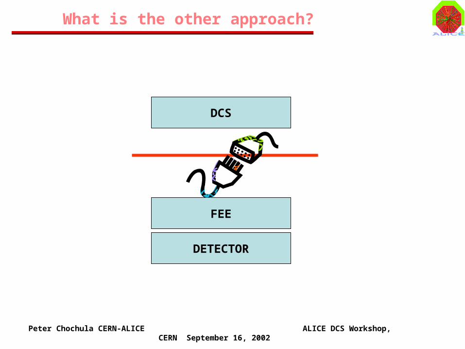
What is the other approach?
DETECTOR
FEE
DCS

Peter Chochula CERN-ALICE ALICE DCS Workshop, CERN September 16, 2002
FEE Architectures in Alice
DETECTOR
Control(setup of DCS Parameters…)
Monitoring (Temp, I, V, Status…)
DCS Supervisory Layer
A/D Conversion(e.g. PLC…)
Detector-DCS“Shared” architecture
Detector “private” architecture
Standard Software Interface
DCS“private” architecture
HARDWARE INTERFACE
PR
IVA
TE
LIN
K
FIE
LD
BU
S
ET
HE
RN
ET
…
PR
IVA
TE
LIN
K
FIE
LD
BU
S
ET
HE
RN
ET
…

Peter Chochula CERN-ALICE ALICE DCS Workshop, CERN September 16, 2002
64 channelsSPD
(2 drift volumes)
AMBRA
PASCAL 64
LV end-ladder card
Interface to DCS
Interface to DCS
HV end-ladder card
FEE hybrid
Example: SDD FEE Design
LV
LV
HV
DCS chipVoltage
Regulators
Both Control and Monitoring based on Private Interfaces

Peter Chochula CERN-ALICE ALICE DCS Workshop, CERN September 16, 2002
Example: SSD FEE Design
(12)A128C
ENDCAPModuleCarrying
ALABUF+ALCAPONE chips
SSD
Hybrid supply card
JTAG monitoring of A128C
JTAG control and setup of ALCAPONE
LV
HV
(8) FEROMCrates
VoltageRegulators
(2) JTAGDistributors
Both Control and Monitoring based on Private Interfaces
Peter Chochula CERN-ALICE ALICE DCS Workshop, CERN September 16, 2002
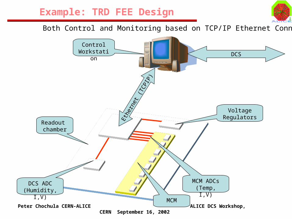
Example: TRD FEE Design
Readout chamber
MCM ADCs(Temp, I,V)
MCM
Eth
erne
t (TC
PIP
)
DCS ADC(Humidity, I,V)
Control Workstation DCS
Voltage Regulators
Both Control and Monitoring based on TCP/IP Ethernet Connection

Peter Chochula CERN-ALICE ALICE DCS Workshop, CERN September 16, 2002
Example: HMPID FEE Design
(6) FEE Segments
ADC 1a
ADC 1b
MCM 2
MCM 1
(6) HV Segments
PLC
Temperature Sensors
DCS (OPC)
Monitoring based on Fieldbus

Peter Chochula CERN-ALICE ALICE DCS Workshop, CERN September 16, 2002
Example: FEE in TPC
ReadoutChamber
FEC
DCS Network
Profibus(Ethernet…)
RCU
Both Control and Monitoring based on Fieldbus
Peter Chochula CERN-ALICE ALICE DCS Workshop, CERN September 16, 2002
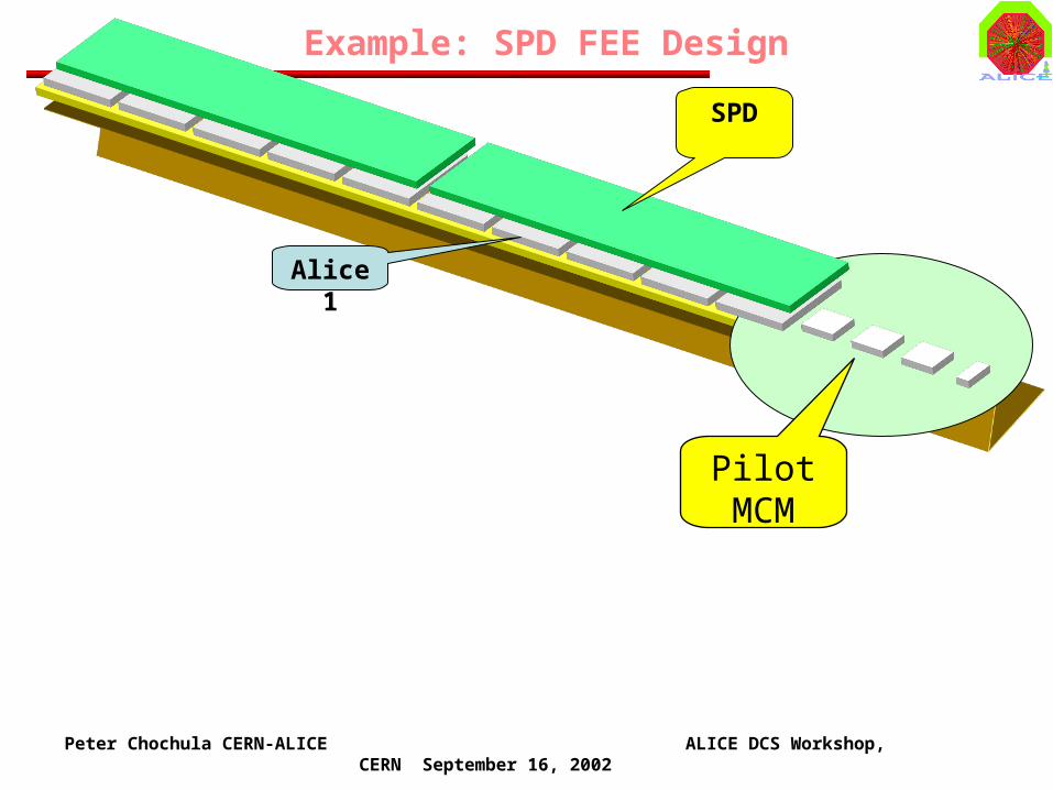
Example: SPD FEE Design
Pilot MCM
SPD
Alice 1
Peter Chochula CERN-ALICE ALICE DCS Workshop, CERN September 16, 2002
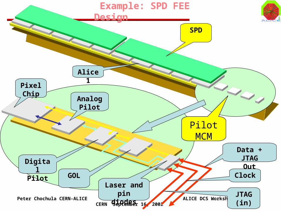
Example: SPD FEE Design
Pilot MCM
AnalogPilot
PixelChip
DigitalPilot
GOLLaser and pin diodes
SPD
Alice 1
Clock
Data + JTAGOut
JTAG(in)

Peter Chochula CERN-ALICE ALICE DCS Workshop, CERN September 16, 2002
Example: SPD FEE Design
PowerSupplies
VoltageRegulators
Half Stave

Peter Chochula CERN-ALICE ALICE DCS Workshop, CERN September 16, 2002
VoltageRegulators
Example: SDD FEE Design
ROUTER
~ 200 m
TTC (Trigger Timing and Control)
DDL (Digital Data Link)
DCS and Monitoring

Peter Chochula CERN-ALICE ALICE DCS Workshop, CERN September 16, 2002
DAQ
Example: SPD FEE Monitoring
Data
Dedicated CPU(Workstation)
DCS
MemoryDIM
PVSS
Halfstave control
VR control JTAG
Router
Monitoring
(Temp)
VR Control, VR Status, I,V
DD
L
Peter Chochula CERN-ALICE ALICE DCS Workshop, CERN September 16, 2002
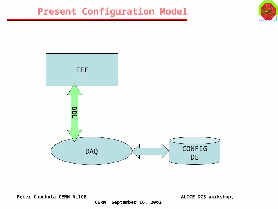
FEE
Present Configuration Model
DAQ
DD
L
CONFIGDB
Peter Chochula CERN-ALICE ALICE DCS Workshop, CERN September 16, 2002
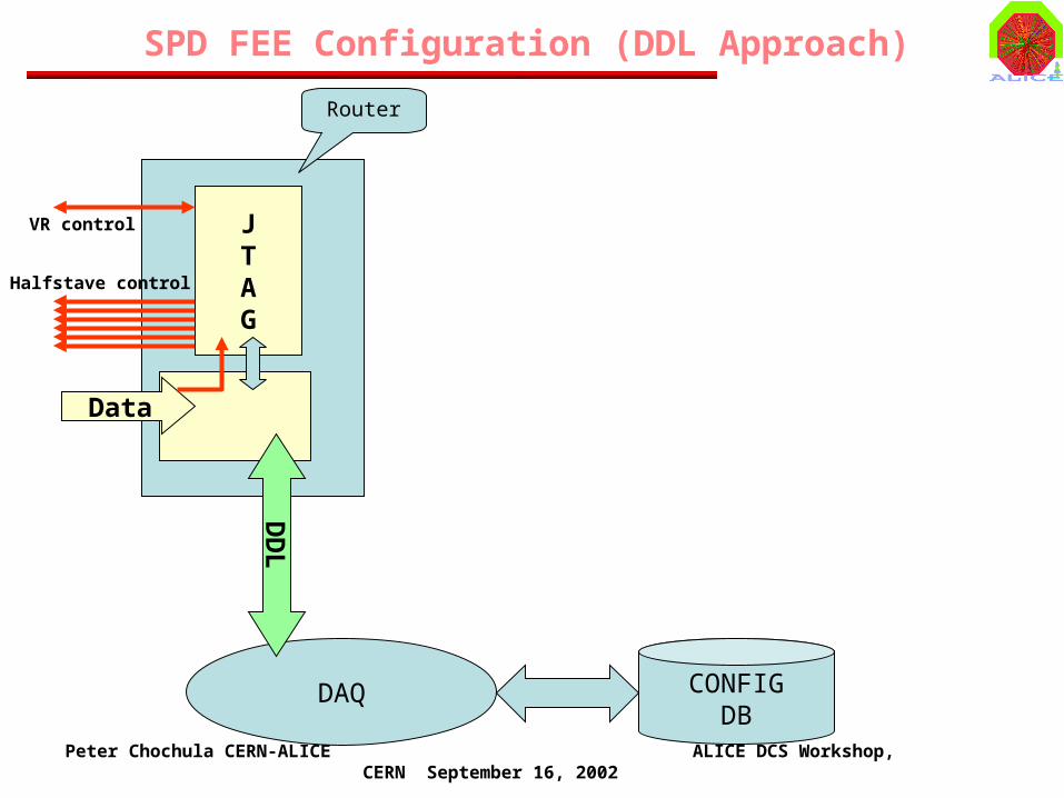
DAQ
SPD FEE Configuration (DDL Approach)
Data
Halfstave control
VR control JTAG
Router
DD
L
CONFIGDB
Peter Chochula CERN-ALICE ALICE DCS Workshop, CERN September 16, 2002
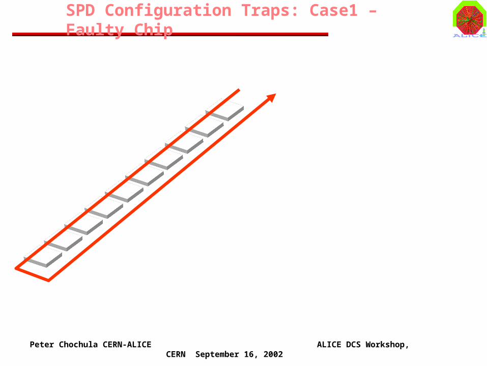
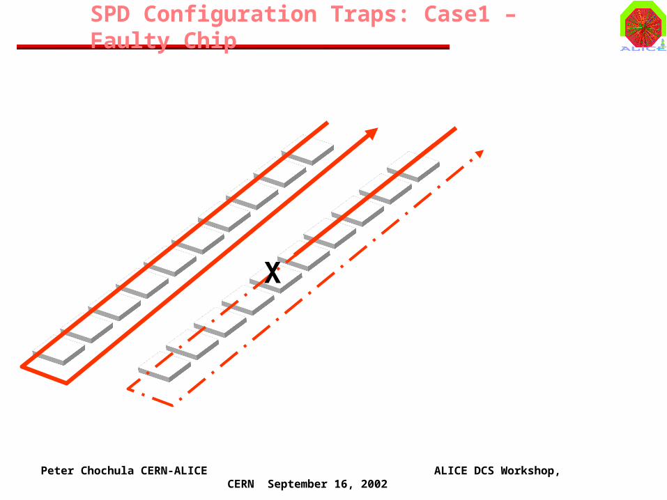
SPD Configuration Traps: Case1 – Faulty Chip
Peter Chochula CERN-ALICE ALICE DCS Workshop, CERN September 16, 2002
SPD Configuration Traps: Case1 – Faulty Chip
X

Peter Chochula CERN-ALICE ALICE DCS Workshop, CERN September 16, 2002
SPD Configuration Traps: Case1 – Faulty Chip
X X

Peter Chochula CERN-ALICE ALICE DCS Workshop, CERN September 16, 2002
SPD Configuration Traps: Case1 – Faulty Chip
X XThe Instruction length has been altered!
The Data and its Size have been changed !

Peter Chochula CERN-ALICE ALICE DCS Workshop, CERN September 16, 2002
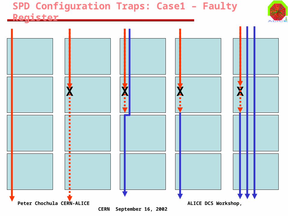
SPD Configuration Traps: Case1 – Faulty Register

Peter Chochula CERN-ALICE ALICE DCS Workshop, CERN September 16, 2002
SPD Configuration Traps: Case1 – Faulty Register
X

Peter Chochula CERN-ALICE ALICE DCS Workshop, CERN September 16, 2002
SPD Configuration Traps: Case1 – Faulty Register
X X

Peter Chochula CERN-ALICE ALICE DCS Workshop, CERN September 16, 2002
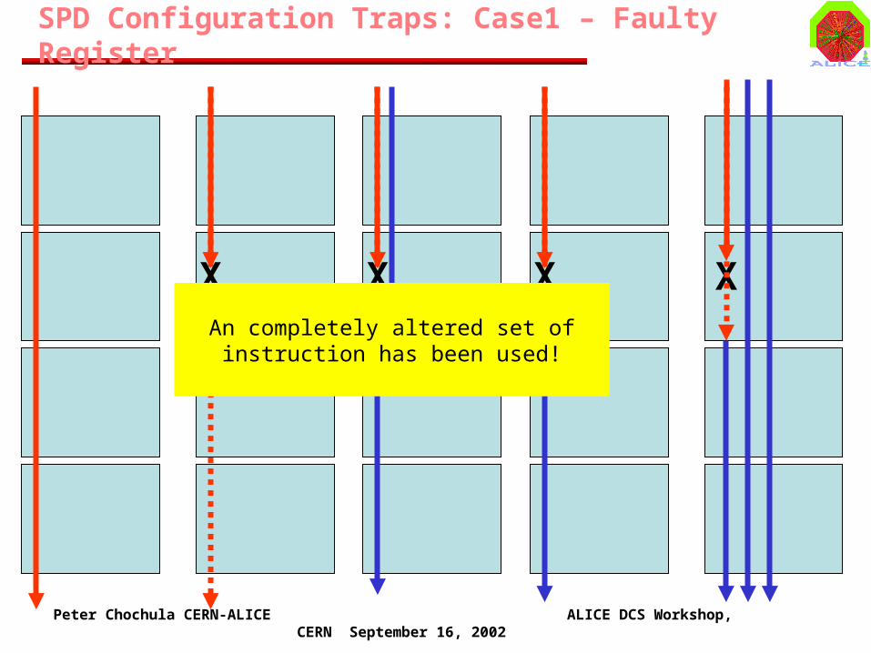
SPD Configuration Traps: Case1 – Faulty Register
X X X
Peter Chochula CERN-ALICE ALICE DCS Workshop, CERN September 16, 2002
SPD Configuration Traps: Case1 – Faulty Register
X X X X
Peter Chochula CERN-ALICE ALICE DCS Workshop, CERN September 16, 2002
SPD Configuration Traps: Case1 – Faulty Register
X X X XAn completely altered set of instruction has
been used!
Peter Chochula CERN-ALICE ALICE DCS Workshop, CERN September 16, 2002
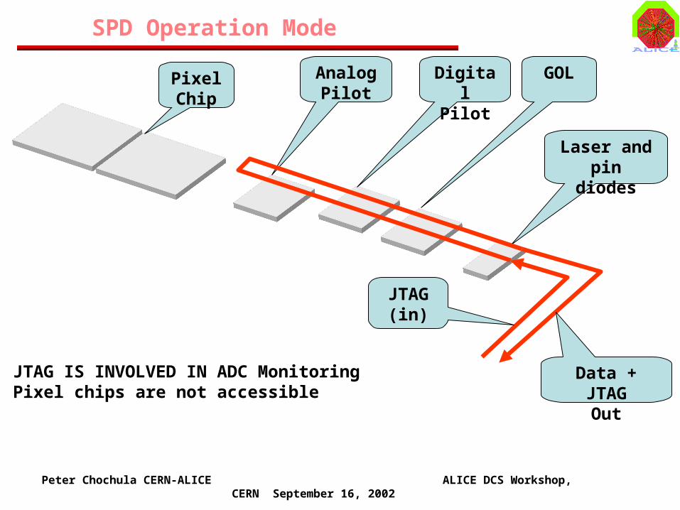
SPD Operation Mode
AnalogPilot
PixelChip
DigitalPilot
GOL
Laser and pin diodes
JTAG(in)
Data + JTAGOut
JTAG IS INVOLVED IN ADC MonitoringPixel chips are not accessible

Peter Chochula CERN-ALICE ALICE DCS Workshop, CERN September 16, 2002
SPD Configuration Mode
AnalogPilot
PixelChip
DigitalPilot
GOL
Laser and pin diodes
JTAG(in)
Data + JTAGOut
JTAG IS INVOLVED IN CHIP CONFIGURATIONADCs on Analog Pilot are not accessible via DCS
Peter Chochula CERN-ALICE ALICE DCS Workshop, CERN September 16, 2002
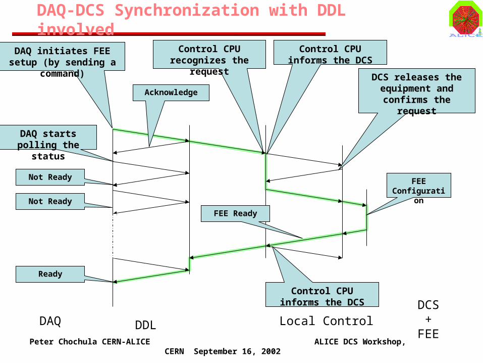
DAQ-DCS Synchronization with DDL involved
DAQ initiates FEE setup (by sending a command)
Acknowledge
DAQ starts polling the status
Not Ready
Not Ready
Ready
Control CPU recognizes the request
Control CPU informs the DCS
DAQ DDL Local ControlDCS
+FEE
FEE Ready
DCS releases the equipment and
confirms the request
Control CPU informs the DCS
FEE Configuration
Peter Chochula CERN-ALICE ALICE DCS Workshop, CERN September 16, 2002
Why do we need involve ECS in configuration?
• It should be possible to reconfigure FEE without the presence of DAQ (recovery from power cut)
• DCS may need to ask for reconfiguration in some cases (e.g. voltage regulator failure)
Peter Chochula CERN-ALICE ALICE DCS Workshop, CERN September 16, 2002
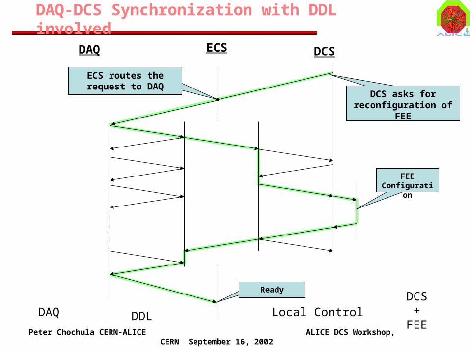
DAQ-DCS Synchronization with DDL involved
DAQ DDL Local ControlDCS
+FEE
FEE Configuration
ECS DCSDAQ
DCS asks for reconfiguration of FEE
ECS routes the request to DAQ
Ready

Peter Chochula CERN-ALICE ALICE DCS Workshop, CERN September 16, 2002
DAQ-DCS Synchronization with DDL involved
DAQ DDL Local ControlDCS
+FEE
FEE Configuration
ECS DCSDAQ
DCS asks for reconfiguration of FEE
Ready
ECS routes the request to local control CPU

Peter Chochula CERN-ALICE ALICE DCS Workshop, CERN September 16, 2002
DAQ
DAQ-DCS Synchronization with ECS involved
Data
Dedicated CPU(Workstation)
DAQ+DCS
MemoryDIM
DCS - PVSS
Halfstave control
VR control JTAG
Router
VR Control, VR Status, I,V
CONFIGDB
ECSDD
L
Peter Chochula CERN-ALICE ALICE DCS Workshop, CERN September 16, 2002
Standard Interfaces
• Detectors responsibility is to provide an OPC server or DIM Server + Client along with the operation specifications
• In this way the choice of hardware implementation is transparent to DCS
• Any hardware modification will be reflected in corresponding software update

Peter Chochula CERN-ALICE ALICE DCS Workshop, CERN September 16, 2002
Standard Interfaces – What does it mean?
• Service based protocol• Client can subscribe to service and
define the update policy• Easy to implement on different
platforms
• Based on COM• Groups and Items represent hardware• Each client should be able to access any
OPC server• Tied to Windows platform
DIM –custom protocol
OPC Server
OPC Group
OPC Item
The Real System
HW0
HW1
HW2OPC ItemOPC Item
OPC – Industrial standard
Server
NameServer S
ervice Info
Request S
ervice
Subscribe to service
Service Data
Commands
Reg
iste
r ser
vice
s
Client
Source: C.Gaspar
Peter Chochula CERN-ALICE ALICE DCS Workshop, CERN September 16, 2002
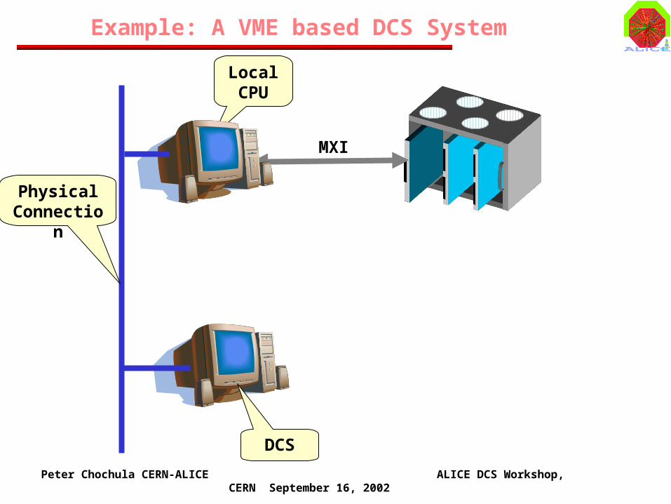
Example: A VME based DCS System
Local CPU
MXI
Physical Connection
DCS
Peter Chochula CERN-ALICE ALICE DCS Workshop, CERN September 16, 2002
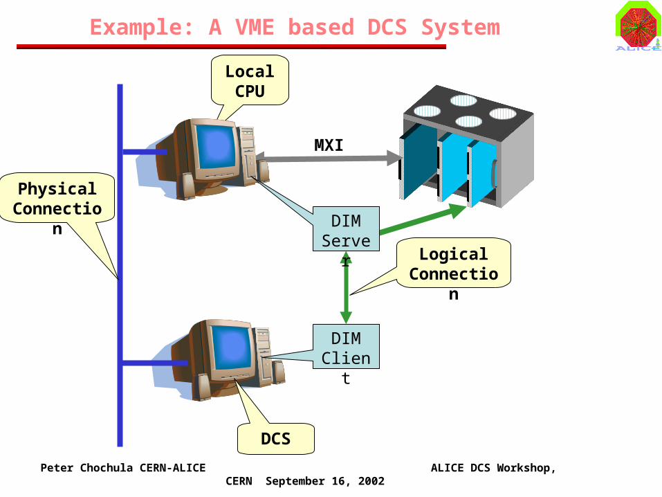
Example: A VME based DCS System
Local CPU
MXI
Physical Connection
DCS
DIMClient
Logical Connection
DIMServer

Peter Chochula CERN-ALICE ALICE DCS Workshop, CERN September 16, 2002
Example: A VME based DCS System
Embedded CPU
Physical Connection
DCS

Peter Chochula CERN-ALICE ALICE DCS Workshop, CERN September 16, 2002
Example: A VME based DCS System
Embedded CPU
Physical Connection
DCS
DIMServer
DIMClient
Logical Connection

Peter Chochula CERN-ALICE ALICE DCS Workshop, CERN September 16, 2002
Example: A VME based DCS System
Embedded CPU
Physical Connection
DCS
DIMServer
DIMClient
Logical Connection
The underlying physical architecture is transparent for DCS
Any modifications will appear at the level of the DIM server (the client may remain the same!)