Embed Size (px)
Citation preview

Peripheral Elements and Technology Associated with Pulsed Power Inertial Fusion:Part 21
Koichi KASUYA2
Department of Energy Sciences, Interdisciplinary Graduate School ofScience and Engineering, Tokyo Institute of Technology,
4259 Nagatsuta, Midori-ku, Yokohama, Kanagawa, Japan 226-8502
1 Supported by the Ministry of Education, Science, Culture and Sports in Japan, the Japan Society for the Promotion of Sciences, Tokyo Institute of Technology, Sandia National Laboratories, Institute of Optoelectronics, MUT, and Institute of Laser Engineering, Osaka University.
2 Collaborations with A.Kasamatsu, Y.Kinoshita, T.Kamiya (TITech), T.Norimatsu, Y.Kozaki ,T.Yamanaka, S.Nakai (Osaka Univ.), T.Renk, C.Olson (SNL), W.Mroz, A.Prokopiuk (MUT).
Presented at the 2nd RCM of the IAEA CRP on "Elements of Power Plant Design for Inertial Fusion Energy", RC-845-F1.30.08, 21 May 2001, Vienna, Austria

Abstract
Various candidate materials were collected from many sources. They were irradiated with intense proton beams at Tokyo Institute of Technology (TITech), with intense nitrogen beams at Sandia National Laboratories (SNL), Albuquerque, and with short pulse UV laser at IOE-MUT, Warsaw. A series of preparatory numerical calculations of x-ray ablations was performed at TITech, which results were compared with the experimental ones. Our aims were to supply necessary data for the future design of inertial fusion reactor chambers. One of the key issues in this field was the ablation thickness of the various chamber wall materials with intense beams under typical inertial fusion reactions. We measured the ablation thickness of various samples, and we also observed the surface conditions of the samples before and after the irradiations with a microscope, an x-ray luminescence composition analyzer and 3D-surface profiler.
Keywords: Inertial fusion, Reactor Chamber Database, Wall Materials, Surface Ablation with Ions, X-rays and UV Laser Light

TITech, DOES, Kasuya Lab.
CONTENTS:
1. Introduction 2. Sample Targets Collected for Beam Exposure 3. Ablation Experiments with Intense Pulsed Ion Beams
3.1. Ablation Experiments with Proton Beams 3.2. Ablation Experiments with Nitrogen Beams
4. Ablation Estimation with Intense X-ray 4.1. Calculation of Ablated Thickness 4.2. Ablation Experiments with X-ray
5.Ablation Experiments with UV Laser Light 6. Summary

Sample Targets Collected for Beam Exposure:
1-a/LiPb/ 16x19x1/ ILE/ Manufactured in Ar environment, Melting Temperature of 233C (Peak)/
1-b/SiC/ 18x23x1 etc./ ILE/ 4-b/Carbon G650S/ 30diax5t(1)/ TITech/ Product of Nilaco
Co. Ltd./6-a/SiC/ 100diax2/ Tokaikonetsu/ Product of Tokaikonetsu,
Normal Pressure Baked, Both Surface Ground/6-b/SiC-Si/ 235x235x5/ Tokaikonetsu/ Product of
Tokaikonetsu, RS420/ 6-c/Al2O3/ 135x125x5/ Tokaikonetsu/ SSA-M, Product of
Nihonkagakutohgyoh, Normal Pressure Baked/

TITech, DOES, Kasuya Lab
MMAARRXX
GGEENNEERRAATTOORR
11..4455MMVV
3322..66kkJJ
((MMAAXX))
PPFFLL
33ΩΩ 114400nnss
TTLL
33ΩΩ 114400nnss
DDIIOODDEE
MMAAGG MMAAIINN
22110000mmmm 33000000mmmm 33000000mmmm 775500mmmm
TTAARRGGEETT
CCHHAAMMBBEERR
Fig. Schematic Diagram of Target Ablation with Intense Proton Beam

TARGET CHAMBERDIODE
TARGET
WINDOWION BEAM
Fig. Configuration of Focused Proton Beams on Target
TITechDOESKasuya Lab.

15
17
19
21
23
25
27
29
31
6 7 8 9 10 11
Energy Density (J/cm2)
Abl
ated
Thi
ckne
ss (µ
m)
Fig. Ablation Thickness vs. Proton Dose (SiC, LiPb and C from Top to Bottom).
TITechDOESKasuya Lab.

Fig. Laser Microscope for Surface Ablation Analysis(Keyence VK-8550 System)

2D Microscope Image of SiC, irradiated with N2 Dose of 3.9J/cm2.
3D Microscope Image of SiC, irradiated with N2 Dose of 3.9J/cm2.

X-ray Luminescence Spectrometer for Surface Composition Analysis (Philips PW2404 System)

0 1 2 3 40
20
40
60
80
100
Dose of Nitrogen Ion [J/cm2]
Si [A
tom
ic N
umbe
r %]
C [A
tom
ic N
umbe
r %]Si
C
Fig. Change of SiC Surface Composition with Different Dose of Nitrogen Ion Irradiation, Measured with X-ray Luminescence Analysis.
TITechDOESKasuya Lab.

Fig. Ablated Thickness vs. Black Body Temperature of X-ray
Source. Calculation in Case of LiF. White Small Box isExperimental Result for Comparison.
1 20
2
4
6
8
Black body temperature kT[keV]
Abl
ated
thic
knes
s [
μ m]
15[J/cm ]
45[J/cm ]
90[J/cm ]
2
2
2
TITechDOESKasuya Lab.

Photon energy hν[KeV]
X-r
ay in
tens
ity I
[pJ・
s]
0 1 2 3 4 50
2
4
6
8
10
kT=100[eV]
kT=300[eV]
kT=500[eV]
The plots of Planck’s law.

X-ray absorption with sliced thin layers.
0,1I0,2I
0,nI
1E 2E nE
x∆

Photon energy hν[KeV]
M.A
.C. μ
[cm
2 /g]
1 2 3 4 5101
102
103
104
105
106
107
Mass absorption coefficient of C

Mass absorption coefficient of LiF [1]
Photon energy hν[KeV]
M.A
.C. μ
[cm
2 /g]
1 2 3 4 5101
102
103
104
105
106
107

Calculation for heat capacity of Carbon’s thin layer
( ) ][2.19)(4 2
1
2 KJdTTCQxRT
T P =+∆∴ ∫ρπ
]/[10975.5 4 gJQsub ×=353 1079.81027.417.17)( −− ××−×+= TTTCp
][42002 KTT sub ==][15.2981 KT =
][000.1 mR =]/[10253.2 36 mg×=ρ
][10000.1 8 mx −×=∆

Calculation for heat capacity of LiF’s thin layer
( ) ][4.3)(4 2
1
2 KJdTTCQxRT
T P =+∆∴ ∫ρπ
]/[10211.8 3 gJQeva ×=
]/[474.2 gKJCp ⋅=
][19542 KTT eva ==][12001 KT =
][000.1 mR =]/[10653.2 36 mg×=ρ
][10000.1 8 mx −×=∆
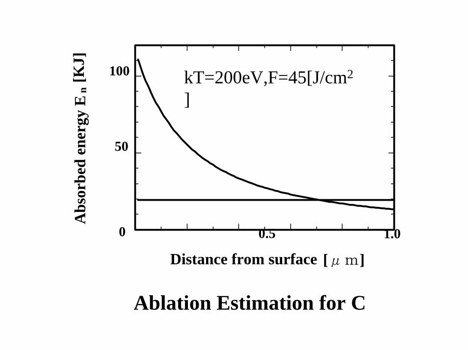
Distance from surface
0.5
Abs
orbe
d en
ergy
En
[KJ]
0 1.0
50
100
[μm]
kT=200eV,F=45[J/cm2
]
Ablation Estimation for C

Abs
orbe
d en
ergy
En
[KJ]
Distance from surface [μm]50 10
25
50 kT=200eV,F=45[J/cm2
]
Ablation Estimation for LiF

0 1000 20000
0.5
1
1.5
100th Layer
400th Layer
700th Layer
X-r
ay in
tens
ity I
[pJ・
s]
Photon energy hν[KeV]
Absorbed energy in one C layer with kT=200[eV],F=45[J/cm2]
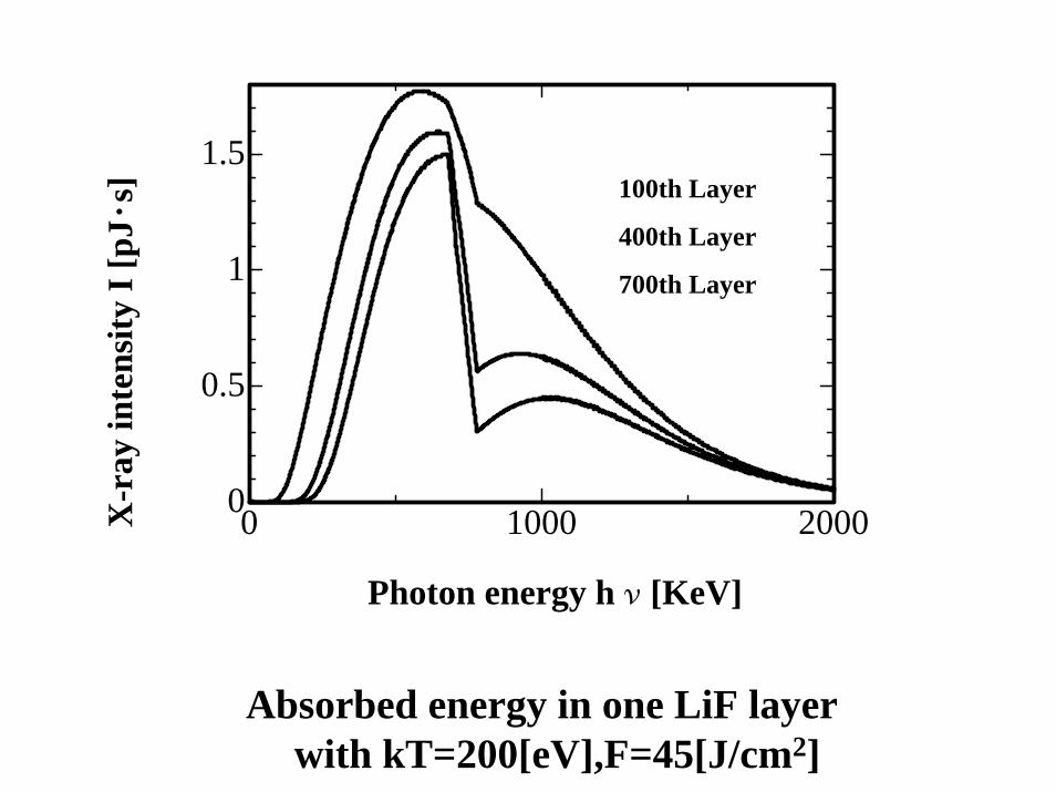
0 1000 20000
0.5
1
1.5
Photon energy hν[KeV]
X-r
ay in
tens
ity I
[pJ・
s] 100th Layer
400th Layer
700th Layer
Absorbed energy in one LiF layer with kT=200[eV],F=45[J/cm2]

1.5
Sublimated depth of C
0
0.5
Subl
imat
ed d
epth
X [ μ
m]
15[J/cm ]2
45[J/cm ]2
90[J/cm ]2
0.5 1
1
Black-body temperature kT[keV]

1 20
2
4
6
8E
vapo
rate
d de
pth
X [ μ
m]
Black-body temperature kT[keV]
15[J/cm ]2
90[J/cm ]2
45[J/cm ]2
Evaporated depth of LiF

Apparatus for UV Laser-Target Interaction

Excimer laser LPX 305i (LPX 300 series) for laser target interaction (EL ≤ 1,2 J, wavelength 157 nm, 193 nm, 248 nm, f = 50 Hz, τ ≅ 20 ns)

3D Analysis of Tungsten Surface with Profiler

2D Analysis of Tungsten Surface with Profiler

3D Analysis of Graphite Surface with Profiler

2D Analysis of Graphite Surface with Profiler

Summary
Under the proton beam irradiation with the dose of about 10J/cm2
per shot, the ablated rates were up to 20 micron for carbon, and 26 micron for LiPb and SiC. The change of the rate was investigated with the change of the dose. Under the nitrogen beam irradiationwith the dose of 4J/cm2, the ablated thickness of up to 6 micron was observed for SiC, while no remarkable ablation was observed for Al2O3. Surface conditions before and after the nitrogen beam irradiation was investigated with a microscope and x-ray fluorescence analysis. SiC surface turned into Si surface, while no discernible change was seen for Al2O3. Under the x-ray irradiation of LiF, SiC/Si and SiC, the ablation thickness of 3 , 0.5 and 0 micron was observed under the dose of 40, 7 and 7J/cm2. Under the UV laser irradiation of W and C, the surface change could be observed with a 3D surface profiler. More experiments and calculations with more advanced methods are scheduled in the near future.
mary