Embed Size (px)
Citation preview

Weeks # 7 Chapter 7: 7.9 Elements of a Transmission Line
For reasons associated with economy, transmission of electric power is done at high voltage by 3-phase, 3-wire overhead system.
The principal elements of a high-voltage transmission line are :
(i) Conductors, usually three for a single-circuit line and six for a double-circuit line. The usual material is aluminum reinforced with steel.
(ii) Step-up and step-down transformers, at the sending and receiving ends respectively. The use of transformers permits power to be transmitted at high efficiency.
(iii) Line insulators, which mechanically support the line conductors and isolate them electrically from the ground.
(iv) Support, which are generally steel towers and provide support to the conductors.
2/27/2017 Power System Technology / Dr. Ramzi A. Abdul-Halem 1
(v) Protective devices, such as ground wires, lightning arrestors, circuit breakers, relays etc. They ensure the satisfactory service of the transmission line. (vi) Voltage regulating devices, which maintain the voltage at the receiving end within permissible limits. All these elements will be discussed in detail in the subsequent chapters
7.10 Economics of Power Transmission While designing any scheme of power transmission, the commercial aspect of the work must be taken into consideration, for achieving the maximum economy. However, the following two fundamental economic principles which closely influence the electrical design of a transmission line will be discussed (i) Economic choice of conductor size
(ii) Economic choice of transmission voltage
2/27/2017 Power System Technology / Dr. Ramzi A. Abdul-Halem 2
Chapter 8: Mechanical Design of Overhead Lines
Introduction
Electric power can be transmitted or distributed either by means of underground cables or by overhead lines.
The underground cables are rarely used for power transmission due to two main reasons.
• Power is generally transmitted over long distances to load centers. Obviously, the installation costs for underground transmission will be very heavy.
• Electric power has to be transmitted at high voltages for economic reasons. It is very difficult to provide proper insulation to the cables to withstand such higher pressures.
2/27/2017 Power System Technology / Dr. Ramzi A. Abdul-Halem 3
Therefore, as a rule, power transmission over long distances is carried out by using overhead lines.
With the growth in power demand and consequent rise in voltage levels, power transmission by overhead lines has assumed considerable importance.
An overhead line is subjected to uncertain weather conditions and other external interferences.
This requests for the use of proper mechanical factors of safety in order to ensure the continuity of operation in the line.
In general, the strength of the line should be such so as to provide against the worst probable weather conditions.
In the following sections, we shall focus our attention on the various aspects of mechanical design of overhead lines.
2/27/2017 Power System Technology / Dr. Ramzi A. Abdul-Halem 4
8.1 Main Components of Overhead Lines An overhead line may be used to transmit or distribute electric power.
The successful operation of an overhead line depends upon the mechanical design of the line.
In general, the main components of an overhead line are:
(i) Conductors: which carry electric power from the sending end station to the receiving end station.
(ii) Supports: which may be poles or towers and keep the conductors at a suitable level above the ground.
(iii) Insulators: which are attached to supports and insulate the conductors from the ground.
2/27/2017 Power System Technology / Dr. Ramzi A. Abdul-Halem 5
(iv) Cross arms: which provide support to the insulators. (v) Miscellaneous items: such as phase plates, danger plates, lightning arrestors, anti-climbing wires etc. The continuity of operation in the overhead line depends upon the careful choice of above components.
8.2 Conductor Materials The conductor is one of the important items as most of the capital expense is invested for it. Therefore, proper choice of material and size of the conductor is of considerable importance. The conductor material used for transmission and distribution of electric power should have the following properties : (i) high electrical conductivity.
2/27/2017 Power System Technology / Dr. Ramzi A. Abdul-Halem 6
(ii) high tensile strength in order to withstand mechanical stresses.
(iii) low cost so that it can be used for long distances.
(iv) low specific gravity so that weight per unit volume is small.
All above requirements are not found in a single material.
Commonly used conductor materials. The most commonly used conductor materials for overhead lines are copper, aluminum, steel-cored aluminum, galvanized steel and cadmium copper.
The choice of a particular material will depend upon the cost, the required electrical and mechanical properties and the local conditions.
All conductors used for overhead lines are preferably stranded in order to increase the flexibility.
2/27/2017 Power System Technology / Dr. Ramzi A. Abdul-Halem 7
In stranded conductors, there is generally one central wire and round this, successive layers of wires containing 6, 12, 18, 24 ...... wires.
8.3 Line Supports The supporting structures for overhead line conductors are various types of poles and towers called line supports.
In general, the line supports should have the following properties :
(i) High mechanical strength to withstand the weight of conductors and wind loads etc.
(ii) Light in weight without the loss of mechanical strength.
(iii) Cheap in cost and economical to maintain.
(iv) Longer life.
(v) Easy accessibility of conductors for maintenance.
2/27/2017 Power System Technology / Dr. Ramzi A. Abdul-Halem 8
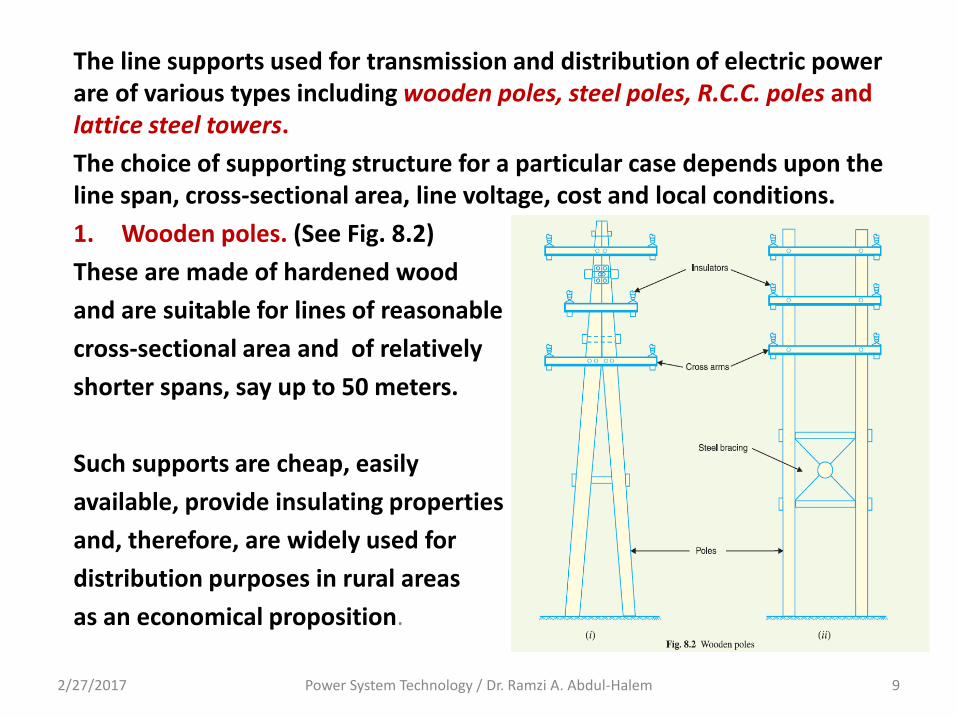
The line supports used for transmission and distribution of electric power are of various types including wooden poles, steel poles, R.C.C. poles and lattice steel towers.
The choice of supporting structure for a particular case depends upon the line span, cross-sectional area, line voltage, cost and local conditions.
1. Wooden poles. (See Fig. 8.2)
These are made of hardened wood
and are suitable for lines of reasonable
cross-sectional area and of relatively
shorter spans, say up to 50 meters.
Such supports are cheap, easily
available, provide insulating properties
and, therefore, are widely used for
distribution purposes in rural areas
as an economical proposition.
2/27/2017 Power System Technology / Dr. Ramzi A. Abdul-Halem 9
2. Steel poles. The steel poles are often used as a substitute for wooden poles.
They possess greater mechanical strength, longer life and permit longer spans to be used.
Such poles are generally used for distribution purposes in the cities.
This type of supports need to be galvanized or painted in order to prolong its life.
The steel poles are of three types
(i) rail (bar) poles
(ii) tubular (cylindrical) poles and
(iii) rolled steel joints.
2/27/2017 Power System Technology / Dr. Ramzi A. Abdul-Halem 10
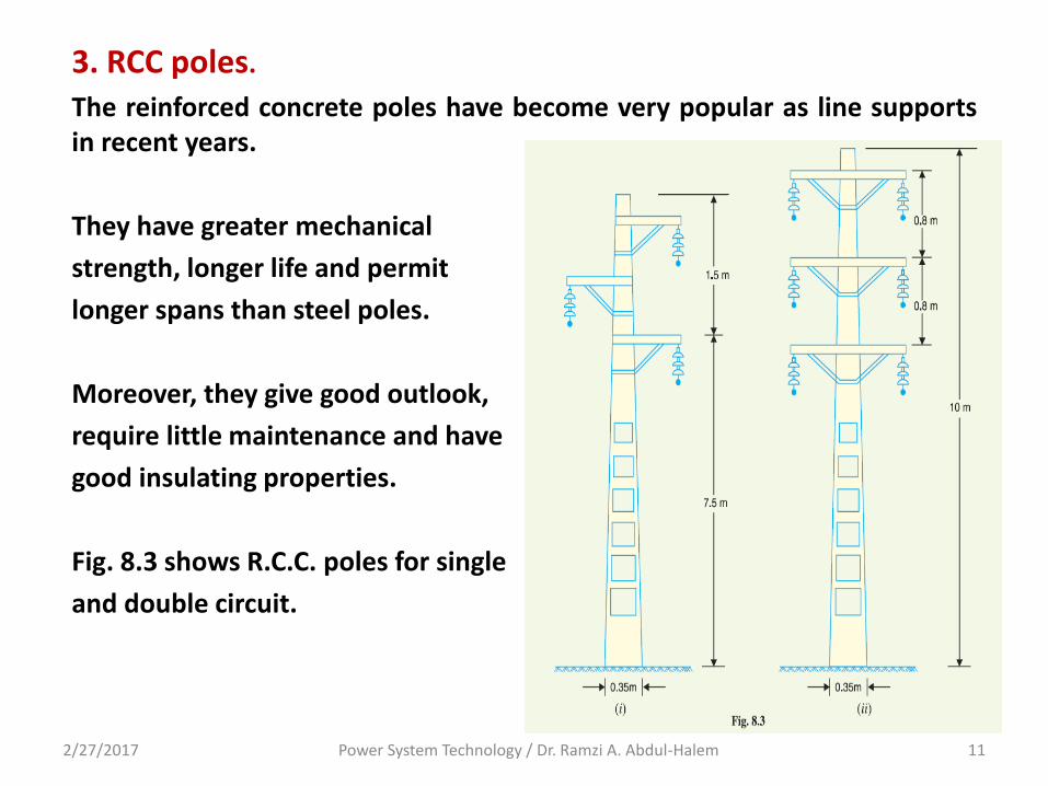
3. RCC poles.
The reinforced concrete poles have become very popular as line supports in recent years.
They have greater mechanical
strength, longer life and permit
longer spans than steel poles.
Moreover, they give good outlook,
require little maintenance and have
good insulating properties.
Fig. 8.3 shows R.C.C. poles for single
and double circuit.
2/27/2017 Power System Technology / Dr. Ramzi A. Abdul-Halem 11
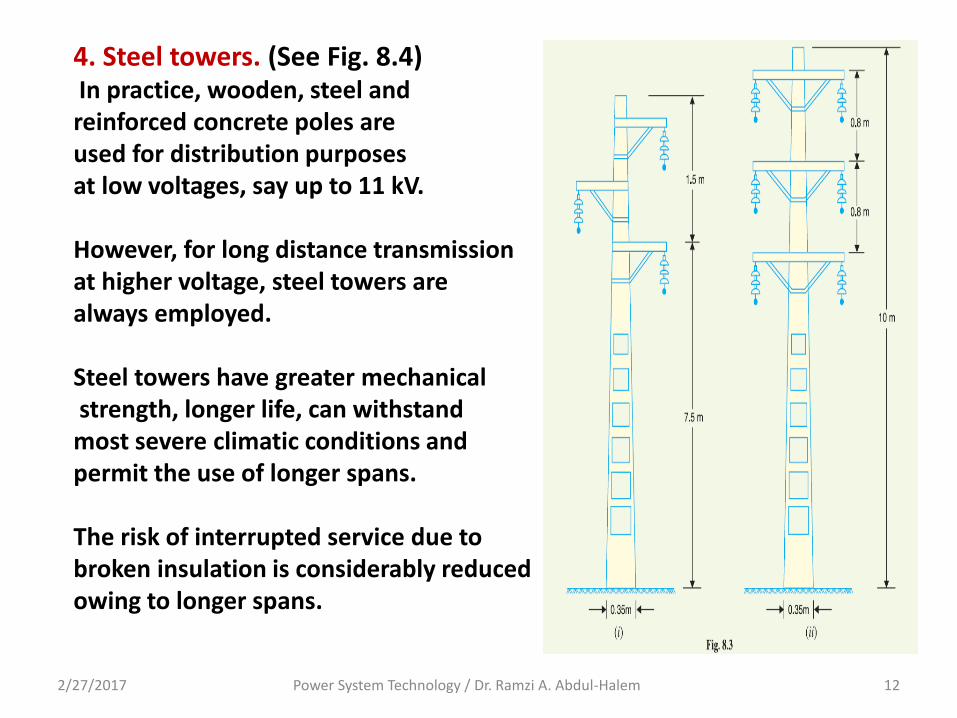
4. Steel towers. (See Fig. 8.4) In practice, wooden, steel and reinforced concrete poles are used for distribution purposes at low voltages, say up to 11 kV. However, for long distance transmission at higher voltage, steel towers are always employed. Steel towers have greater mechanical strength, longer life, can withstand most severe climatic conditions and permit the use of longer spans. The risk of interrupted service due to broken insulation is considerably reduced owing to longer spans.
2/27/2017 Power System Technology / Dr. Ramzi A. Abdul-Halem 12
8.4 Insulators The overhead line conductors should be supported on the poles or towers in such a way that currents from conductors do not flow to earth through supports i.e., line conductors must be properly insulated from supports. This is achieved by securing line conductors to supports with the help of insulators. In general, the insulators should have the following desirable properties : (i) High mechanical strength in order to withstand conductor load, wind load etc.
(ii) High electrical resistance of insulator material in order to avoid leakage currents to earth.
(iii) High relative permittivity of insulator material in order that dielectric strength is high.
2/27/2017 Power System Technology / Dr. Ramzi A. Abdul-Halem 13
(iv) The insulator material should be non-porous, free from impurities and cracks otherwise the permittivity will be lowered.
(v) High ratio of puncture strength to flashover.
The most commonly used material for insulators of overhead line is porcelain but glass, steatite and special composition materials are also used to a limited extent.
Porcelain is produced by firing at a high temperature a mixture of kaolin, feldspar and quartz.
It is stronger mechanically than glass, gives less trouble from leakage and is less effected by changes of temperature.
2/27/2017 Power System Technology / Dr. Ramzi A. Abdul-Halem 14
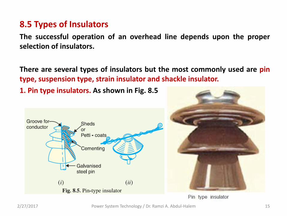
8.5 Types of Insulators The successful operation of an overhead line depends upon the proper selection of insulators.
There are several types of insulators but the most commonly used are pin type, suspension type, strain insulator and shackle insulator.
1. Pin type insulators. As shown in Fig. 8.5
2/27/2017 Power System Technology / Dr. Ramzi A. Abdul-Halem 15
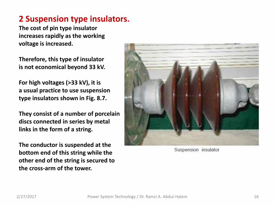
2 Suspension type insulators. The cost of pin type insulator increases rapidly as the working voltage is increased. Therefore, this type of insulator is not economical beyond 33 kV. For high voltages (>33 kV), it is a usual practice to use suspension type insulators shown in Fig. 8.7. They consist of a number of porcelain discs connected in series by metal links in the form of a string. The conductor is suspended at the bottom end of this string while the other end of the string is secured to the cross-arm of the tower.
2/27/2017 Power System Technology / Dr. Ramzi A. Abdul-Halem 16
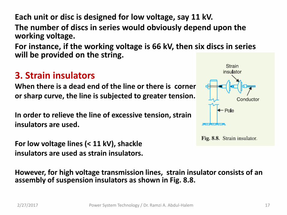
Each unit or disc is designed for low voltage, say 11 kV. The number of discs in series would obviously depend upon the working voltage. For instance, if the working voltage is 66 kV, then six discs in series will be provided on the string.
3. Strain insulators When there is a dead end of the line or there is corner or sharp curve, the line is subjected to greater tension. In order to relieve the line of excessive tension, strain insulators are used. For low voltage lines (< 11 kV), shackle insulators are used as strain insulators. However, for high voltage transmission lines, strain insulator consists of an assembly of suspension insulators as shown in Fig. 8.8.
2/27/2017 Power System Technology / Dr. Ramzi A. Abdul-Halem 17
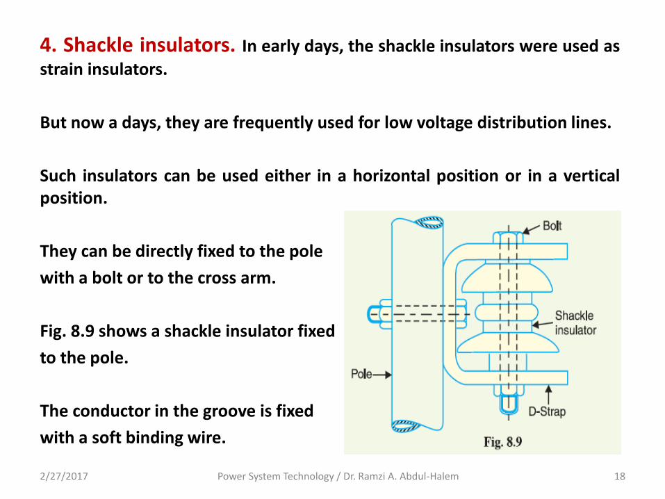
4. Shackle insulators. In early days, the shackle insulators were used as
strain insulators.
But now a days, they are frequently used for low voltage distribution lines.
Such insulators can be used either in a horizontal position or in a vertical position.
They can be directly fixed to the pole
with a bolt or to the cross arm.
Fig. 8.9 shows a shackle insulator fixed
to the pole.
The conductor in the groove is fixed
with a soft binding wire.
2/27/2017 Power System Technology / Dr. Ramzi A. Abdul-Halem 18


![7.9 notes[1]](https://img.pdfslide.us/doc/110x75/547c9b7bb4af9fa0158b51b3/79-notes1.jpg)