Embed Size (px)
Citation preview

IPS-I-GN-335
This Standard is the property of Iranian Ministry of Petroleum. All rights are reserved to the owner. Neither whole nor any part of this document may be disclosed to any third party, reproduced, stored in any retrieval system or transmitted in any form or by any means without the prior written consent of the Iranian Ministry of Petroleum.
PERIODICAL INSPECTION AND TESTING
OF
ELEVATORS
ORIGINAL EDITION
MAY 1997
This standard specification is reviewed and updated by the relevant technical committee on Mar. 2005. The approved modifications are included in the present issue of IPS.

May. 1997
IPS-I-GN-335
1
CONTENTS : PAGE No.
1. SCOPE ............................................................................................................................................ 3
2. REFERENCES ................................................................................................................................ 3
3. UNITS .............................................................................................................................................. 3
4. GENERAL NOTICE ........................................................................................................................ 3
4.1 Personal Safety ....................................................................................................................... 3
4.2 Duties of Inspectors................................................................................................................ 4
4.3 Arrangement for Inspection ................................................................................................... 4
4.4 Recommended Equipment..................................................................................................... 4
5. DEFINITIONS AND TERMINOLOGY ............................................................................................. 5
6. PERIODIC INSPECTIONS AND TESTS ........................................................................................ 5
7. INSPECTION AND TESTS NOT LONGER THAN ONE MONTH AS ROUTINE INSPECTION FOR ELECTRIC ELEVATORS ....................................................................................................... 6
7.1 Hoistway Doors ....................................................................................................................... 6
7.2 Hoistway Door or Gate Interlocks-Locking Function and Closed Position ..................... 6
7.3 Hoistway Door Interlocks-Auxillary Lock ............................................................................. 7
7.4 Hoistway Door or Gate-Separate or Combination Mechanical Locks and Contacts ....... 7
7.5 Power-Door Operation............................................................................................................ 8
7.6 Car Doors or Gates and Electric Contacts ........................................................................... 8
7.7 Emergency Doors in Blind Hoistways .................................................................................. 9
7.8 Emergency-Release Switch in Car ........................................................................................ 9
7.9 Inspection Made from Inside of Car ...................................................................................... 9
7.10 Inspection Made Outside of Hoistway .............................................................................. 11
7.11 Inspection Made from Top of Car ...................................................................................... 12
7.12 Inspection Made in Overhead Machinery Space and in Machine Room ....................... 22
7.13 Inspection Made in Pit ........................................................................................................ 29
8. INSPECTIONS AND TESTS NOT LONGER THAN TWELVE MONTHS FOR ELECTRIC ELEVATORS.................................................................................................... 34
8.1 Inspection of the Governor Rope System .......................................................................... 34
8.2 Inspection and Test of Safeties, Each Twelve Months ..................................................... 34
8.3 Test of Buffers, Each Twelve Months ................................................................................. 37
8.4 Test of Emergency Power Operation .................................................................................. 38
8.5 Test of the Closing Force of the Door System................................................................... 38
9. INSPECTIONS AND TESTS, EACH FIVE YEARS FOR ELECTRIC ELEVATORS ................... 39
9.1 Inspection and Test of Governors and Safeties ................................................................ 39
9.2 Test of Buffers, Each Five Years ......................................................................................... 42
9.3 Test of Normal and Final Termianl Stopping Devices....................................................... 43
10. ROUTING INSPECTION NO LONGER THAN ONE MONTH FOR HYDRAULIC ELEVATORS…………………………………………………………………………………………… 44

May. 1997
IPS-I-GN-335
2
10.1 Inspection Made from Inside of the Car............................................................................ 44
10.2 Inspection Made Outside of Hoistway .............................................................................. 44
10.3 Inspection Made from Top of Car ...................................................................................... 44
10.4 Inspection Made in Machinery Spaces or Machine Room.............................................. 44
10.5 Inspection Made in Pit ........................................................................................................ 46
11. INSPECTION AND TESTS EVERY TWELVE MONTHS FOR HYDRAULIC ELEVATORS............................................................................................................................... 47
11.1 Terminal Stopping Devices ................................................................................................ 47
11.2 Relief Valve Setting............................................................................................................. 47
11.3 Static Load Test .................................................................................................................. 48
11.4 Governor and Safety Test .................................................................................................. 48
11.5 Buffer Test ........................................................................................................................... 48
12. THREE YEARS INSPECTION AND TEST................................................................................. 48
12.1Flexible Hydraulic Hose and Fitting Assemblies and Flexible Couplings ..................... 48
12.2 Inspection of Unexposed Portions of Pistons ................................................................. 48
12.3 Pressure Tanks ................................................................................................................... 48
13. FIVE YEARS INSPECTION AND TEST ..................................................................................... 48
13.1 Governor and Safety Test .................................................................................................. 48
13.2 Oil Buffer Test ..................................................................................................................... 49
14. INSPECTION AND TESTS AFTER AN IMPORTANT MODIFICATION OR AFTER AN ACCIDENT ....................................................................................................... 49
APPENDICES:
APPENDIX A TYPICAL WIRE ROPE CONSTRUCTIONS............................................................ 50
APPENDIX B DESCRIPTIONS AND SCHEMATIC LAYOUTS OF VARIOUS TYPES OF SAFETIES AND GOVERNORS............................................................ 52
APPENDIX C HANDLING AND SOCKETING OF WIRE ROPE ................................................... 74
APPENDIX D CHECKLIST FOR INITIAL AND PERIODIC INSPECTION AND TEST OF ELECTRIC ELEVATORS ............................................................... 81
APPENDIX E CHECKLIST FOR INITIAL AND PERIODIC INSPECTION AND TEST OF HYDRAULIC ELEVATORS ............................................................ 84

May. 1997
IPS-I-GN-335
3
1. SCOPE
This Standard is intended to serve as a guide in the task of inspecting electric and hydraulic elevators for passengers and goods. While this Standard is, in general, based on the requirements of the IPS-M-GN-370. It also contains recommendations for the inspection of equipment which is not required to conform to that standard. It should be used in whole or in part as a practical guide for the inspection and testing of elevators.
Note:
This standard specification is reviewed and updated by the relevant technical committee on Mar. 2005. The approved modifications by T.C. were sent to IPS users as amendment No. 1 by circular No 258 on Mar. 2005. These modifications are included in the present issue of IPS.
2. REFERENCES
Throughout this Standard the following dated and undated standards/codes are referred to. These referenced documents shall, to the extent specified herein, form a part of this standard. For dated references, the edition cited applies. The applicability of changes in dated references that occur after the cited date shall be mutually agreed upon by the company and the vendor. For undated references, the latest edition of the referenced documents (including any supplements and amendments) applies.
IPS (IRANIAN PETROLEUM STANDARD)
IPS-M-GN-370 "Material and Equipment Standard for Elevators"
NFPA (NATIONAL FIRE PROTECTION ASSOCIATION)
NFPA No. 70 "National Electrical Code"
3. UNITS
This Standard is based on International System of Units (SI), except where otherwise specified.
4. GENERAL NOTICE
4.1 Personal Safety
Inspectors shall be cautioned that there are many potential hazards involved in the inspection of elevators.
Since any accident can be not only disabling but may be fatal, inspectors are reminded of the hazards involved and that records show a number of accidents involving inspectors.
The inspector should be suitably clothed before starting the inspection. Wearing of loose clothing, particularly neckties, should be avoided. Keep buttons, particularly those on cuffs, buttoned. The inspector should at all times be alert for moving objects, and when on top of an elevator car, for moving counterweights, hoistway projections such as beams, adjacent moving cars, cams, and other equipment attached thereto or mounted in the hoistway. The overhead clearance should always be noted as a number of fatal accidents have resulted from cars running into limited overhead spaces while inspectors were on top of the cars. Similarly, when working in the pit, the inspector should always note the position of the car and also keep clear of descending counterweights in the hoistways. The power supply line disconnect switch should be opened when it is desired to prevent movement of the elevator or when inspecting electrical parts.

May. 1997
IPS-I-GN-335
4
Before starting the inspection of an elevator, the inspector should first determine that the operating device, emergency stop switch, and any other safety devices or switches are in proper working order and in the proper position for inspection.
When dual or attendant operation is provided, the changeover switch should be in the position of operation from the car only.
Before inspecting an elevator in a bank of "Group Automatic Operation" elevators, have the elevator to be inspected disconnected from the group operation.
Where means of communication is provided in the car, determine that it is operative.
Where a top-of-car operating device is provided, use it to operate the car when on top of the car instead of depending on an operator in the car.
Inspectors should never enter pits containing water. A number of fatal electric shock accidents have occurred under such conditions.
For additional safe practices, see "Safety Precautions" outlined in the applicable clause in this Standard and manufacturer’s recommendation.
4.2 Duties of Inspectors
The duties of inspectors are as follows:
a) In making acceptance inspections of new or altered installations or initial inspections of existing installations, to determine whether all parts of the installation conform to the requirements of the IPS-M-GN-370 or regulations and whether the required safety devices function as required therein.
b) In making routing inspections, or periodic inspections and tests of existing installations, or of new installations after they have been approved for operation by the enforcing authority, to determine that the equipment is in a safe operating condition, has not been altered except in conformity to IPS-M-GN-370, and performs in accordance with test requirements.
c) To report the results of his inspection in accordance with IPS-M-GN-370.
It is not the function or duty of inspectors to make any repairs or adjustments to the equipment.
4.3 Arrangement for Inspection
The inspecting authority or the inspector should request the Company to make the following arrangements prior to an inspection or test:
a) Provide qualified personnel to perform the tests specified in IPS-M-GN-370.
b) In the case of hydraulic elevators, clean such portions of the equipment as tanks and piston rods prior to the inspection as required.
The inspector should be accompanied by a person familiar with the operation of the elevator to assist him during his inspections.
4.4 Recommended Equipment
a) Routine Inspections
The following equipment is recommended:
1) A flashlight with a nonconductive case for inspecting wire ropes and other equipment in locations where sufficient natural or artificial light is not available.
2) A 1.8 m rule of nonconductive material.
3) A set of thickness gages.
May. 1997
IPS-I-GN-335
5
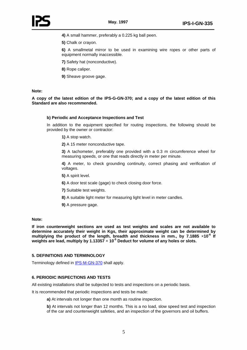
4) A small hammer, preferably a 0.225 kg ball peen.
5) Chalk or crayon.
6) A smallmetal mirror to be used in examining wire ropes or other parts of equipment normally inaccessible.
7) Safety hat (nonconductive).
8) Rope caliper.
9) Sheave groove gage.
Note:
A copy of the latest edition of the IPS-G-GN-370; and a copy of the latest edition of this Standard are also recommended.
b) Periodic and Acceptance Inspections and Test
In addition to the equipment specified for routing inspections, the following should be provided by the owner or contractor:
1) A stop watch.
2) A 15 meter nonconductive tape.
3) A tachometer, preferably one provided with a 0.3 m circumference wheel for measuring speeds, or one that reads directly in meter per minute.
4) A meter, to check grounding continuity, correct phasing and verification of voltages.
5) A spirit level.
6) A door test scale (gage) to check closing door force.
7) Suitable test weights.
8) A suitable light meter for measuring light level in meter candles.
9) A pressure gage.
Note:
If iron counterweight sections are used as test weights and scales are not available to determine accurately their weight in Kgs, their approximate weight can be determined by multiplying the product of the length, breadth and thickness in mm., by 7.1885 ×10⁻⁶ If weights are lead, multiply by 1.13357 × 10⁻⁵ Deduct for volume of any holes or slots.
5. DEFINITIONS AND TERMINOLOGY
Terminology defined in IPS-M-GN-370 shall apply.
6. PERIODIC INSPECTIONS AND TESTS
All existing installations shall be subjected to tests and inspections on a periodic basis.
It is recommended that periodic inspections and tests be made:
a) At intervals not longer than one month as routine inspection.
b) At intervals not longer than 12 months. This is a no load, slow speed test and inspection of the car and counterweight safeties, and an inspection of the governors and oil buffers.
May. 1997
IPS-I-GN-335
6
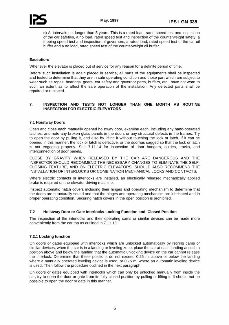
c) At intervals not longer than 5 years. This is a rated load, rated speed test and inspection of the car safeties, a no load, rated speed test and inspection of the counterweight safety, a tripping speed test and inspection of governors, a rated load, rated speed test of the car oil buffer and a no load, rated speed test of the counterweight oil buffer.
Exception:
Whenever the elevator is placed out of service for any reason for a definite period of time.
Before such installation is again placed in service, all parts of the equipments shall be inspected and tested to determine that they are in safe operating condition and those part which are subject to wear such as ropes, bearings, gears, car safety and governor parts, buffers, etc., have not worn to such an extent as to affect the safe operation of the installation. Any defected parts shall be repaired or replaced.
7. INSPECTION AND TESTS NOT LONGER THAN ONE MONTH AS ROUTINE INSPECTION FOR ELECTRIC ELEVATORS
7.1 Hoistway Doors
Open and close each manually opened hoistway door, examine each, including any hand-operated latches, and note any broken glass panels in the doors or any structural defects in the frames. Try to open the door by pulling it, and also by lifting it without touching the lock or latch. If it can be opened in this manner, the lock or latch is defective, or the doorhas sagged so that the lock or latch is not engaging properly. See 7.11.14 for inspection of door hangers, guides, tracks, and interconnection of door panels.
CLOSE BY GRAVITY WHEN RELEASED BY THE CAR ARE DANGEROUS AND THE INSPECTOR SHOULD RECOMMEND THE NECESSARY CHANGES TO ELIMINATE THE SELF-CLOSING FEATURE, AND ON ELECTRIC ELEVATORS, SHOULD ALSO RECOMMEND THE INSTALLATION OF INTERLOCKS OR COMBINATION MECHANICAL LOCKS AND CONTACTS.
Where electric contacts or interlocks are installed, an electrically released mechanically applied brake is required on the elevator driving machine.
Inspect automatic hatch covers including their hinges and operating mechanism to determine that the doors are structurally sound and that the hinges and operating mechanism are lubricated and in proper operating condition. Securing hatch covers in the open position is prohibited.
7.2 Hoistway Door or Gate Interlocks-Locking Function and Closed Position
The inspection of the interlocks and their operating cams or similar devices can be made more conveniently from the car top as outlined in 7.11.13.
7.2.1 Locking function
On doors or gates equipped with interlocks which are unlocked automatically by retiring cams or similar devices, when the car is in a landing or leveling zone, place the car at each landing at such a position above and below the landing that the automatic unlocking device on the car cannot release the interlock. Determine that these positions do not exceed 0.25 m, above or below the landing where a manually operated leveling device is used, or 0.75 m, where an automatic leveling device is used. Then follow the procedure outlined in the next paragraph.
On doors or gates equipped with interlocks which can only be unlocked manually from inside the car, try to open the door or gate from its fully closed position by pulling or lifting it. It should not be possible to open the door or gate in this manner.
May. 1997
IPS-I-GN-335
7
7.2.2 Closed position of hoistway door or gate
With the car door or gate in the closed position and with the hoistway door or gate fully open, close the hoistway door or gate slowly from the landing side until the maximum clear opening is reached at which the actuation of the elevator operating device will cause the car to start. Measure the distance from the nearest face of the door jamb or gate sill to the nearest edge of the door or gate, or between the rigid meeting edges of biparting doors. Determine that from this position, the door cannot be reopened from the landing side (see also 7.3 and 7.11.13).
The measured distance should not exceed the dimensions indicated in the following paragraphs:
1) Horizontally Sliding or Swinging Doors or Vertically Sliding Counterweighted Doors or Gates: 9.5 mm.
2) Vertically Sliding Biparting Counterbalanced Doors: 19 mm, from their stopped position, when equipped with a fire resistive nonshearing, noncrushing edge on the lower edge of the upper door section.
7.3 Hoistway Door Interlocks-Auxillary Lock
Where a 100 mm, locking range is permitted, an auxiliary lock is required which is incorporated either in the door closing mechanism or consists of a rack attached to the landing sill or top track and an engaging pawl on the door. When the doors are power closing, the auxiliary lock is usually placed on the closing mechanism to prevent damage if attempt is made to reopen the door by power while it is in the 100 mm, locking range.
Where power-closing doors of the horizontally sliding type or doors equipped with door closers and interlocks have a 100 mm, locking range, place the door in the position as determined in 7.2 which will permit the operating device to start the car.
With the car door or gate in the closed position, slowly close the hoistway door and try to reopen it from the landing side from any point between the 100 mm., position and a position where the clear open space between the nearest face of the door jamb and the jamb edge of the door or the clear open space between the meeting edges of biparting doors is 9.5 mm. From any position within this range, it may be possible to open the door up to, but not beyond the 100 mm, position.
7.4 Hoistway Door or Gate-Separate or Combination Mechanical Locks and Contacts
Separate mechanical locks used in combination with separate electric contacts are not permitted.
Combination mechanical locks and electric contacts of the hoistway unit system are permitted only on freight elevators under restricted conditions.
7.4.1 Locking function
Inspect mechanical locks operated manually from the car, where used, with hoistway door or gate electric contacts. With the door or gate in the fully closed position, pull on the door or gate, which should be held closed by the lock. Determine that the locking member is in a position to lock the door when or before the contact is closed by the door or gate.
Where the locking members of such devices are operated by car cams, which are usually but not necessarily of the stationary type, place the door or gate in the fully closed position and move the car a sufficient distance away from the floor to permit the locking member to lock the door or gate. With the car in this position, pull on the door, which should be held closed by the lock. Release the lock manually and open the door or gate. Then slowly close it to the position where the electric contact just closes and note whether the locking member is in a position to lock the door. It may be necessary to check this from the car top.
7.4.2 Closed position of door or gate
The closed position of the door or gate electric contacts used with either separate mechanical locks

May. 1997
IPS-I-GN-335
8
or combination mechanical locks and electric contacts should be determined as outlined for interlocks in 7.2.2. Determine that from this position the door or gate cannot be reopened from the landing side.
Where contacts cannot be inspected from within the car, inspect them from the car top as outlined in 7.11.13.
7.5 Power-Door Operation
Where the closing of car and hoistway doors is controlled by momentary pressure or by automatic means, check the operation and if the force necessary to prevent power closing of horizontally sliding doors seems excessive, check as outlined in 7.11.13 for inspection of power-door operating devices on top of cars.
Where a power-closed car door is provided with a reopening device, with automatic and continuous pressure operation under certain conditions, the reopening device should be tested as indicated for the applicable types (see 7.5.1, 7.5.2 and 7.5.3).
In any of these tests (7.5.1, 7.5.2 and 7.5.3) where the inspector uses an object to test the reopening device, it should not be inserted when the door is nearing its fully closed position.
7.5.1 Mechanical reopening device (safety edge)
Actuate the device while the doors are being closed and note whether car and hoistway doors stop and reopen.
7.5.2 Electronic reopening device
Place an object in front of the leading edge of the car door at various positions while it is being closed. The car and hoistway doors should stop and reopen.
7.5.3 Photoelectric reopening device
Determine the location of the light beam or beams with relation to the car floor. While the car and hoistway doors are being closed, obstruct each light beam which should cause the doors to stop and reopen. Where an invisible beam is used, the position of the beam can be determined by an examination of the equipment.
7.6 Car Doors or Gates and Electric Contacts
7.6.1 Examination of doors or gates
Examine the car doors or gates and note any broken, bent or sprung members. Operate doors or gates to determine that they operate freely and that bottom sill-guide tracks or bottom guiding members are in place, securely fastened, and are not worn enough to permit the doors or gates to come out of their tracks at any position of their travel (see also 7.11.14).
7.6.2 Test for closed position
With the hoistway doors or gates in the closed position, check the closed position of the car doors or gates as outlined in 7.2.2 for hoistway door or gate interlocks. A door or gate is considered to be in the closed position when the clear open space between the leading edge of the door or gate and the nearest face of the jamb or sill does not exceed 50 mm, or, in the case of biparting doors, when the door panels are within 50 mm, of contact with each other.

May. 1997
IPS-I-GN-335
9
7.7 Emergency Doors in Blind Hoistways
Check the operation of the self-closing device and functioning of the self-locking device, where provided. Where door interlocks are provided, check them for closed position and locking function and check door electric contacts, where provided, for closed position as outlined for other hoistway doors.
Where neither interlocks nor electric contacts are provided, the locking device provided should be a type which cannot be opened except by a key which will not unlock any other door or device in the building. In such cases, if the doors are not provided with door electric contacts, installation of contacts should be recommended. Determine whether emergency access doors are unobstructed.
7.8 Emergency-Release Switch in Car
Examine the emergency-release switch in the car, if provided, and note whether it is in the inoperative position and the glass cover is in place and unbroken. Recommend immediate replacement of missing or broken glass. Some codes require these switches to be of the key-operated constant-pressure type. In such cases, the switch should return automatically to the off position and the key should be removable only when the switch is in the off position.
7.9 Inspection Made from Inside of Car
7.9.1 Car enclosure
All interior lighting should be checked for proper operation. Determine that the car enclosure is structurally sound and is securely fastened to the platform. Determine that capacity plates and any required certificates are posted in the car. Report any evidence of alterations or additions to the car which have materially changed the car weight.
Check car enclosure for conformity to IPS-M-GN-370.
Determine that top exit panels are in place, secured, and not obstructed, and whether side emergency exit doors of passenger elevators are closed and locked.
If ventilating fans are installed inside the car, determine that they are properly guarded, adequately supported, and securely fastened in place and not obstructing the emergency exit.
7.9.2 Car illumination
7.9.2.1 Normal illumination
Examine lighting fixtures to determine whether they are securely fastened, and have the required protection. Determine that sufficient illumination is provided.
7.9.2.2 Emergency illumination
When emergency lighting is supplied, check its operation by disconnecting the normal lighting supply. Where the emergency for lighting is supplied by batteries, check that such batteries are in good condition and properly maintained, and that any recharging equipment is operable.
7.9.3 Operating and control devices
7.9.3.1 Car-Switch operation
Operate the car switch to determine whether the operating handle returns to the stop position and latches in this position when the hand is removed. Note any evidence of excessive friction, or
May. 1997
IPS-I-GN-335
10
weakened or broken centering springs. Operate the emergency stop switch and note whether the car stops promptly.
For inspection of car emergency release switch, see 7.8.
7.9.3.2 Continuous-Pressure operation
Operate the car in each direction by means of the operating buttons or other devices in the car to determine that they do not stick or bind, are properly marked, and that the car stops when released.
Test the operation of the emergency stop switch as outlined in 7.9.3.1.
7.9.3.3 Automatic operation and signal operation
Operate the car, making stops in both the up and down direction. At each stop, open the car door or gate and note the relation of the car platform sill to the landing sill. Note any tendency of operating push buttons to stick. Test the operation of the emergency stop switch as outlined in 7.9.3.1.
7.9.3.4 Hand rope, lever, wheel or crank operation
Examine the operating rope and note if there are any broken wires. Where a centering rope is provided, determine that it will stop the car in each direction.
Where an operating rope is provided, stop the car at each landing and determine whether lock stop balls on the rope require relocation to prevent starting of the car. Determine that the locking jaws are not rounded over and the springs actuating the lock are intact, with the proper tension to prevent the rope stop balls from being pulled through the rope lock.
Where lever, wheel, or crank operation is provided, operate the car in both directions of travel and make stops at several landings. Note any excessive lost motion or sticking of the operating device.
7.9.3.5 Dual and attendant operation
Where the elevator can be operated at times only from the car and at times as an automatic elevator (dual or attendant operation), check the operation (Par. 7.8) under both operating conditions and determine that car emergency-release switches, where provided for short circuiting door or gate interlocks or electric contacts, are inoperative when the elevator is on automatic operation.
7.9.4 Car floor, sills, and landing sills
7.9.4.1 Car floor
Determine the condition of the car floor and car and landing sills. Where a floating platform is provided, it should be noted that, THIS TYPE OF PLATFORM CONSTITUTES A SERIOUS HAZARD AND IT IS SUGGESTED THAT THE INSPECTOR RECOMMEND TO THE COMPANY THAT THE CONTACTS ON SUCH PLATFORMS WHICH FUNCTION TO SHORT CIRCUIT THE CAR GATE OR DOOR CONTACT BE PERMANENTLY DISCONNECTED SO THAT THE CAR CAN BE OPERATED ONLY WHEN THE CAR GATE OR DOOR IS CLOSED.
A floating platform is a car platform which permits operation of the car with the car gate or door open. Try operating the car from the landing operating device with a load of 13.5 kg on the platform with the car gate or door in the open position.
This test should be repeated with the test load placed in various locations. The car should not operate under such conditions.

May. 1997
IPS-I-GN-335
11
Note:
Elevator systems may, however, use isolated platform construction that may have load weighing signaling devices, etc. Such use is not prohibited.
7.9.4.2 Hinged car platform sills
Visually examine the sill plate for cracks, wear, broken welds, or loose rivets. Check the area under the sill for foreign material which would prevent proper operation at the landing.
Check all bolts on the counterweight housing and stop angles. Inspect the ropes or chains which connect the sill to the counterweight. Check pivot points and sheaves for wear and proper lubrication.
Inspect the hand lever and linkage for excess wear, and loose or missing cotter pins or bolts.
7.9.4.3 Hinged hoistway landing sills
Visually examine the sill plate for cracks, wear, broken welds, or loose rivets. Check the area under the sill for foreign material which would prevent proper operation at the landing.
Check all bolts on the counterweight housing and stop angles. Inspect the ropes or chains which connect the sill to the counterweight. Check pivot points and sheaves for wear and proper lubrication.
7.9.5 Protection of projections and recesses in hoistways
Examine guards under landing sills to determine that they are firmly secured in place. GUARDS SHOULD BE RECOMMENDED ON EXISTING ELEVATIORS NOT SO EQUIPPED.
7.9.6 Car emergency signals for elevators without a designated operator in the car
Check the operation of the emergency signaling devices for compliance with the requirements of IPS-M-GN-370.
Check the operation of the audible signaling device (alarm) and means of two-way conversation or telephone, whichever is supplied.
Where the emergency power supply for these signal means is supplied by batteries, check that such batteries are in good condition and are being properly maintained.
7.10 Inspection Made Outside of Hoistway
7.10.1 Hoistway enclosures and doors
Where openwork type enclosures and doors are permitted and used, check enclosure panels at all floors and note whether they are securely fastened in place. Also determine that wire netting or mesh required by the applicable regulations is in place and securely fastened.
For inspection of hoistway doors, see 7.1 to 7.5, 7.11.13 and 7.11.14.
7.10.2 Hoistway access switches
Hoistway access switches are required under certain conditions. Determine that the switch key is kept in a location where it is available only to authorized persons.

May. 1997
IPS-I-GN-335
12
7.10.3 Car parking and hoistway door unlocking devices
7.10.3.1 Parking device
Check operation of parking (service key) device and determine that all parts of the device are free to operate and that the door cannot be opened unless the car is at the landing.
7.10.3.2 Unlocking devices
Key shall be of a special shape to prevent easy duplication or use of common tools. Check any keyhole plates or escutcheons on doors and determine that they are intact, securely fastened in place, and not deformed.
The key or unlocking device shall be kept on the premises by a person responsible for the maintenance of the elevators and only readily accessible to qualified persons in case of emergency.
7.10.4 Rope and rope fastening inspection-counterweight in separate hoistway
Where the counterweight runs within a separate enclosure outside the hoistway, each rope and its fastening should be inspected at the door in such enclosure nearest to the top of the hoistway. Determine that inspection doors in the counterweight enclosure are self-closing and locked. Instruct the operator to move the car a short distance at a time and inspect the ropes. For details of rope and rope-fastening inspection, see 7.11.4 through 7.11.6 if inspection doors are not provided in the counterweight enclosure their installation should be recommended.
7.10.5 Car platform guards (aprons)
Where a car leveling or truck zoning device is provided, a smooth metal guard extending a distance below the platform floor equal to the depth of the leveling or truck zone plus 76 mm, shall be provided on the entrance side of the car platform. Place the car 0.6 m or 0.9 m above one of the landings with the hoistway door open and inspect the guard to determine that it is in place and securely fastened. In some cases, this guard can be inspected from the pit with the car at the bottom terminal landing.
7.11 Inspection Made from Top of Car
7.11.1 General-safety precautions
The following precautions should be observed when making inspections from the top of the car:
a) Where outlets are provided on the top of the car, use a 50 volts hand lamp with a suitable lamp guard and reflector. Extension cords should not be hung on car or counterweight ropes.
b) Be sure to have a firm and secure surface, free of oil and grease, on which to stand. If the car top is not clean, notify the owner to clean it before the inspection is made. Blowing out with compressed air to be avoided.
c) Use special care where car tops are curved or domed.
d) Test the strength of the car top before subjecting it to the entire body weight. Avoid standing on the car top emergency exit cover.
e) Be sure to have a firm hold on the crosshead or other parts of the car structure when the car is moving. Never hold onto the ropes. The practice of holding ropes may result in a serious injury on an elevator equipped with 2-to-1 roping.
f) If there is an adjacent elevator in the hoistway, be careful to keep all parts of the body within the limits of the oistway of the elevator being inspected. Keep inside the limits of the

May. 1997
IPS-I-GN-335
13
car area when the car is moving, to avoid ontact with counterweights or projections in the hoistway. Be alert to counterweights of elevators which may be ocated in or adjacent to the hoistway of the elevator being inspected.
g) If the car is equipped with a top-of-car operating device, check it for proper operation before using it to operate he car during inspection.
h) If no top-of-car operating device is available, instruct the operator in the car to move the car at the slowest ossible speed only and in the specified direction. Request the operator to repeat the instruction each time before oving the car. In the case of signal and collective-operation elevators or any elevator whose reversal at the terminals is automatically ontrolled, warn the operator that if he is instructed to reverse the direction of the car between terminals, e must do so by means of the reversal switch in the car. Some existing automatic-operation elevators are provided with up and down continuous-pressure type operating buttons in the car to operate the car when making inspections, and a switch is provided on the controller to make these inspection buttons operative and to simultaneously open the circuit of the hall operating push-buttons, and in the case of collective-operation, the operating buttons in the car. Where such inspection buttons are provided, make them operative and instruct the operator in the car to use them to operate the car. Where no inspection devices are provided, either in or on top of the car, see General Safety Precautions in 7.13.1.
i) Where an emergency stop switch is located on the car top, check its operation and be prepared to use it in case of an emergency.
j) Where the overhead car clearance is limited, it is important to observe overhead obstructions. This is particularly important where a working platform is provided on top of the car. Generally working platforms are prohibited.
k) As a general rule, it is advisable to start the inspection from the top of the hoistway.
7.11.2 Top car clearance
Before making any of the inspections or tests outlined in 7.11 determine the available top car clearance. Where possible, this should be determined by placing the car with its floor level with the top terminal landing. Care must be exercised in measuring this clearance from the car top as, in many existing elevators, the top clearance may be insufficient to permit a man to stand on the car top when the car floor is level with the top terminal landing. WHERE THE CLEARANCE APPEARS TO BE INSUFFICIENT, the car should be stopped at or below the top landing and the top car clearance should be determined as follows:
Measure:
a) The distance from the top of the car crosshead to the nearest obstruction directly above it.
b) The projection of any sheaves, or other equipment mounted in or on the car crosshead, above the top of the crosshead.
c) The distance from the top of any equipment mounted on top of the car (not the car crosshead) to the nearest obstruction directly above it.
d) The distance, if any, the car floor is below the top terminal landing this distance, if any, is to be subtracted from the distances measured in "a" and "c". The question of whether or not the top car clearance, as measured, is adequate or conform to code requirements, cannot be determined until the counterweight runby and counterweight buffer compression have been measured.
Caution:
The projection of rope fastenings or guide shoes above the car structure is not to be considered an encroachment on the top car clearance. However, excessive projection

May. 1997
IPS-I-GN-335
14
should not be permitted if interference with sheaves or other equipment would be encountered on maximum overtravel.
7.11.3 Counterweight and counterweight buffer
Examine counterweights as follows:
a) Determine that lock nuts and cotter pins at the top and bottom of the rods and the frame rods are in place and that filler weights (subweights) are securely held in place.
b) Determine that the counterweight guide shoes are securely fastened to the frame and that the guiding members are not worn excessively. Also determine if swivel-type or roller-type guide shoes are free to move as intended.
c) If a car counterweight is provided, and it runs in the same guides as the drum counterweight, it should be located above the drum counterweight. Examine the clearance between the car counterweight and durm counterweight below it. This clearance should be not less than 200 mm. Observe the car counterweight during acceleration and retardation of the car and note whether there is any undue slackening of the hoisting ropes.
d) Where 2-to-1 roping is used, inspect the counterweight sheave and bearings for condition and adequacy of lubrication. Also determine that the sheave bearings are securely fastened to the counterweight frame and whether sheave guards, where required, are in place. Hammer test the sheave rim and spokes.
e) Where 1-to-1 roping is used, inspect the counterweight rope fastenings as outlined in 7.11.4.
f) Where the counterweight buffer is attached to the counterweight, determine that the buffer fastening bolts are tight. Determine that the oil buffer is filled with oil to the proper level.
g) Check fastenings for compensating chains or ropes to determine that they are securely fastened to the counterweight. It is required that compensating chains be fastened to the steel counterweight frames directly or by a bracket. Ropes and their fastenings should be examined as outlined in 7.11.4 through 7.11.7. Determine that compensating chains are so suspended that they will not catch on beams or other projections in the hoistway.
h) Where provided, inspect counterweight safeties as outlined in 7.13.15.
7.11.4 Wire rope fastenings and sheaves
Check the crosshead data plate and rope data tag required by IPS-M-GN-370. Examine the condition of the wire rope fastenings at the car and counterweight ends and also the fastening of the governor and car safety rope at the carreleasing carrier. The examination should include the following:
7.11.4.1 Determine that rope fastenings at both the car and counterweight ends of the ropes have been properly made up. For requirements for babbitted fastenings for wire rope.
7.11.4.2 Where an auxiliary rope fastening device is provided, examine and determine that the auxiliary device is carrying the load because of rope stretch or rope failure at the regular rope fastening. Where an electric switch is provided to open motor and control circuits when the auxiliary rope fastening device on each rope operates, determine that it is properly adjusted.
7.11.4.3 Where none babitted shackle rod and rope socket are separate pieces, determine that the fastening between the two parts is positive and such as to prevent their separation.
"U" type clamps are prohibited for suspension ropes.
Where clamps are used on governor rope fastenings the following is recommended:
- The clamps be drop forged.
- Both members of the clamp be provided with seats conforming to the construction lay of the rope.

May. 1997
IPS-I-GN-335
15
- Not less than three clamps be used for each rope.
- The rope be passed around metal thimbles.
- If "U" type clamps, they should be installed with the "U" section on the non-tension side of the rope.
- Clamp bolts and nuts are in place and tight but not over tightened. On "U" type clamps, the dead end of the rope should be deformed approximately 1/3 of its diameter. This usually requires approximately 5.5 N-m torque on the nuts for 13 mm, rope and 6.8 N-m for 16 mm, rope. Where both members of the clamps have seats the torque should conform to the manufacturers recommendation.
Where spliced eyes are used, rope strands should not be pulled out of position and strand ends should not project from the rope.
7.11.4.4 Where babbitted sockets are used, check car and counterweight fastenings for conformity to applicable requirements.
Also, note any change in color of steel wires caused by overheating when the socket was made up. Determine whether there are any broken wires at the point where the rope enters the socket. This is especially important in the case of the car suspension ropes of drum machines. Such breaks usually occur at rope fastenings just below the top of the small end of the socket and can,in many cases, be detected by prying the individual wires in the strand with a sharp instrument, such as the blade of a knife. Also determine that the rope has not lost its lay where it enters the socket, and whether any strands bulge out.
In some of the older drum machine installations, cast iron blocks mounted between the car crosshead channels were used to support the babbitted rope thimbles without the use of shackle rods. In such cases, inspection of the babbitted sockets can only be made by landing the car and producing enough slack to permit the sockets to become visible. Suspension ropes which pass around a spool or spools in the car cross head before attachment to the socket fastenings should be slackened to observe the condition of that part of the rope which bears on the spools.
7.11.4.5 Where 1-to-1 roping is used, determine that any steel plates used to support the rope shackle rods are attached to the underside or to the webs of the car frame members in such a manner that the fastening bolts or rivets are not in direct tension. Where rope equalizing springs are used, determine that shackle rods are not worn at the point where they pass through the steel supporting plate.
7.11.4.6 Where 2-to-1 roping is used:
a) Examine dead end rope hitches as outlined in 7.11.4.1 through 7.11.4.4. Determine that steel plates for supporting rope shackle rods are placed on top of the supporting beams or are located in such a manner that the bolts supporting the suspension plates are not in direct tension. Determine that suspension members are securely fastened in place and that no bending of the supporting members has occurred.
b) Inspect car sheave and sheave bearings for condition and for adequacy of the lubrication. Determine that the sheave bearings are securely fastened to the frame members. Hammer test rim and spokes of sheave (see 7.12.3).
Determine that sheave guards, where required, are in place.
7.11.4.7 Where counterweights are located within a separate enclosure, inspect the rope fastenings at the same time the counterweight ropes are inspected (see 7.10.4).
7.11.4.8 On winding drum machines, required refastening of hoisting ropes are each 12 months for machines located over hoistway and 24 months for machines located below or at side of hoistway.
At least one turn of rope is required on the drum when the car is resting on fully compressed buffer.
7.11.5 Wire rope inspection
Examine suspension ropes and note if they conform to the code requirements. IPS-M-GN-370 requires the wire rope data to be shown on the car crosshead data plate. Wire rope requirements

May. 1997
IPS-I-GN-335
16
are specified in IPS-M-GN-370.
Internal breakage of wire ropes is difficult to detect and consequently, may be a greater hazard than surface wear. The surface of the rope may show little or no wear, but if the rope is bent over a short radius, the individual wires will snap and in extreme cases the rope may be broken by hand. Such failures are more likely to occur in governor and compensating ropes where the ropes are lightly loaded and the ratio of sheave diameter to rope diameter is small.
When replacing suspension, compensating, and car or drum counterweight ropes, all ropes in a set must be replaced.
The ropes in the set should all be from the same manufacturer and of the same material, grade, construction and diameter, and preferably, cut from the same reel.
The lengths of all wire ropes in a set of suspension ropes, and consequently the rope tensions, should be substantially equal if maximum rope life and efficiency are to be obtained. If the tensions do not appear to be substantially the same, equalization of the rope lengths should be recommended.
If ropes are dirty of overlubricated, a proper inspection may not be possible unless the dirt or excess lubricant is removed (see 7.11.7 for proper lubrication).
It should be noted that it is not possible to describe the inspection procedure for every single type of wire rope installation nor to outline every detail of the inspection procedure. The inspector should use his best judgment in making the inspection and in selecting his location from which a proper examination of the rope can best be made. For example, the suspension ropes of an overhead drum machine cannot be examined from the top of the car and there are many vertical and horizontal hydraulic installations where the ropes will lead down a shaft remote from the elevator itself.
of the unexamined section of ropes and examine them later from the machine room or overhead machinery space, or from the pit.
The following method based on field experience is recommended as a guide for the inspection and evaluation of wire ropes:
Move the car downward 0.6 m or 0.9 m, at a time and examine each rope at each of these stops.
Note when broken wires begin to appear. Thereafter check at frequent intervals to determine the rate of increase in the
number of broken wires. Any rapid increase in the number of broken wires is significant.
Count the number of broken crown wires in a rope lay measured along the length of a rope within which the spiral strands complete one turn about the axis. A lay may be considered as a section of rope approximately 6½ times the diamter of the rope, that is, 84.5 mm, for 13 mm, rope and 104 mm, for 16 mm, rope:
a) Single or double wrapped traction machines should have hoisting or compensating ropes replaced:
- If the broken wires are equally distributed among the strands, when the number of broken wires per rope lay in the worst section of rope exceeds the values shown in column A of Table 7.1; or
- if the distribution of broken wires is unequal, and broken wires predominate in 1 or 2 strands, when the number of broken wires per rope lay in the worst section of the rope exceeds the values shown in column B of Table 7.1; or
- if 4 or 5 wires, side by side, are broken across the crown of any stand, when the number of broken wires per rope lay in the worst section of rope exceeds values shown in column C of Table 7.1; or
- if any unfavorable conditions, such as corrosion (red dust or rouge), excessive wear of individual wires in the strands, unequal tension, poor sheave grooves, etc., exist, and the number of broken wires exceeds 50 percent of the values indicated in Table 7.1 for any of the three conditions described above.

May. 1997
IPS-I-GN-335
17
TABLE 7.1 TYPES
OF WIRE ROPE
A B C
6 ´ 19 Class 8 ´ 19 Class
24-30* 32-40*
8-12* 10-16*
12-20* 16-24*
* The upper limits may be used when inspections are made at least monthly by a competent person.
Note:
6 × 19 class rope has 6 strands with 16 to 26 wires per strand. 8 × 19 class rope has 8 strands with 16 to 26 wires per strand.
b) On drum machines, the ropes should be replaced:
- If the broken wires are substantially equally distributed among the strands, when the number of broken wires per rope lay in the worst section of rope exceeds 12- 18*; or
- if wire breaks predominate in one or two strands, when the number of broken wires per rope lay in the worst section of rope exceeds 6-12.
c) Ropes should be replaced whenever their actual diameter is reduced below the value shown in Table 7.2 on any type of machine.
TABLE 7.2 Nominal Diameter
in mm 13 14 14 17 19 25
Actual reduced Diameter in mm
12.2 13.2 14.8 15.8 17.8 23.4
Caution:
Breaks in the valleys of the ropes, while infrequent,may be an indication of internal breaks. The ropes should be replaced when there is more than one broken wire in the valleys of a rope lay.
A valley break is one in which the outside wire of a strand breaks in the Immediate vicinity of the point where it contacts a wire or wires of an adjacent strand, generally at a point not visible when the wire rope is examined externally. In other words, one broken end of the wire is long enough to reach from one valley to the next one and the other end of the break generally cannot be seen. This is not to be confused with a broken outside wire when the original break occurred at a worn crown and a secondary fracture has occurred near the point where two adjacent strands make contact. In this case, a piece of wire has broken out and is missing, and generally both ends of the broken wire remaining are visible.
Note that where preformed rope is used, greater care is required on inspection in order to detect broken wires which do not protrude from the surface of the rope.
d) Governor ropes should be inspected and replaced as outlined for suspension and compensating ropes of traction machines in 7.11.5-a.
Check governor rope for conformity to IPS-M-GN-370 requirements. IPS-M-GN-370 requires the governor rope data to be shown on a metal plate attached to the speed governor. If a governor rope has been replaced since the last inspection, determine that the new rope is of the same material, diameter and construction as that specified on the governor marking plate.

May. 1997
IPS-I-GN-335
18
7.11.6 Compensating chains inspection
Examine compensating chains and fastenings for excessive wear, damage, or deterioration. Sash cord wear is no indication of chain damage but may result in undesirable noise in the elevator operation. If such noise prevails, suggest that the sash cord be replaced.
The car has to be placed at its lowest possible portion with landing door opened. A safe access is made with a ladder or scaffolding check & control the over speed governor jaws or grips, car bottom steelwork and enclosure, compensating rope & fastenings. As this stage spring and/or buffers, suspension sheaves of compensating rope & over speed governor sheave in pit are of good access for inspection.
7.11.7 Wire rope lubrication
The lubrication of a wire rope applied during its manufacture may not last the full life of the rope and the rope may have to be relubricated periodically. Proper lubrication of suspension ropes will prolong rope life by reducing abrasive action of wire on wire or strand on strand and will retard deterioration of the fibre cores, eliminate distortion of the rope, and retard corrosion by providing a moisture repellent coating. As a practical guide to the need for lubrication, a finger wiped in a sheave groove should show a faint smudge and have a slightly oily feel. If this test leaves the finger dry and clean, lubrication is advisable.
As excessive or improper lubricants may, in the case of traction elevators, seriously reduce the available traction and cause rope slippage, the lubricants and the amount used should be limited to those supplied or approved by established elevator or wire rope manufacturers. Slide of the ropes during acceleration or retardation may be an indication that the lubrication is excessive. To determine this, it will usually by necessary to observe the ropes where they pass around the driving machine sheave during acceleration and retardation. Some rope creepage is normal.
In the case of drum machines, excessive lubrication does not create a hazardous condition but should not interfere with the proper inspection of ropes.
Governor wire ropes must not be lubricated after installation as the lubricant may interfere with the ability of the governor jaws to stop the governor rope and apply the safety or it may reduce the traction between the governor rope and the governor sheave and prevent proper functioning of the speed governor.
7.11.8 Normal terminal stopping devices
Extreme caution should be observed if the car clearance is limited. Run the car to the top of its travel at slow speed to examine the normal terminal stopping device. (See paragraph "j" of the General Safety Precautions, 7.11.1.)
On traction elevators and on most of the more recent drum type installations, this device usually consists of a switch or switches mounted on top of the car actuated by cams in the hoistway, or switch or switches installed in hoistway actuated by cams on the car.
In some cases, however, normal terminal stopping devices of traction elevators may be located in the machine room or overhead machinery space and be mechanically connected to and driven by the car. Where the normal terminal stopping device of traction elevators is so located and the required broken-drive device is located on top of the car, manually open it with the car at rest. The opening of this switch should prevent the car from starting. See 7.11.9 for inspection and test of final terminal stopping devices.
In the case of older drum machine installations, the device is part of an automatic stop-motion switch mounted on and operated directly by the driving machine (see 7.12.11) on existing hand-rope operated elevators, stop balls mounted on the operating device to stop the car at the terminals. Examine these stop balls for proper location and fastening.
Determine that stopping switches and cams are in correct alignment and are securely fastened in place. Also determine the condition of the limit switch rollers, a reduction of the effective roller diameter due to either wear or loss of the tires may interfere with or prevent proper opertion of the switch. excessively worn car guide shoes and worn limit rollers combined, may cause cars to
May. 1997
IPS-I-GN-335
19
overrun their terminals.
If the equipment is in proper condition and sufficient overhead clearance exists, make a test of top normal terminal stopping devices with empty car at rated speed. If overhead clearance is limited, this test should be made by operating the elevator from inside the car. Repeat operation with bottom normal terminal stopping devices. On each of these stops, the car should stop at or near the terminal landing and before the final terminal stopping device operates.
7.11.9 Upper final terminal stopping device
The upper final terminal stopping device should be located as close to the terminal landing as possible without interfering with the normal terminal stopping device but before the car strikes the overhead.
Note:
Before testing final terminal stopping devices from the top of the car, determine whether the potential switch on the controller is of the manually or electrically restored type. If of the manually restored type, the operation of the final terminal stopping device should not be tested from the car unless someone is in the machine room to reclose the controller switch when instructed to do so by the inspector.
Run the car up the hoistway at inspection speed until the upper final terminal stopping switch may be reached by hand. Use an insulated object to open this switch, and try to start the car in each direction.
THE CAR SHOULD NOT MOVE AND IF IT MOVES, THE INSPECTION SHOULD NOT BE CONTINUED UNTIL THIS DEFFECT IS CORRECTED.
Check the fastening and alignment of the switch and cam. The switch roller should strike on the bevel surface of the cam and not on the top. If properly located and adjusted. The roller should centerlaterally on the cam, assuring free motion of the roller arm and positive opening of the switch contact without damaging the switch. Drum type elevators requires installation of the final terminal stopping switches in the hoistway and in addition, requires a switch operated by the machine automatic stop-motion device to open the control circuit to the reversing switch and mainline motor switch on the controller. See 7.12.11 for inspection and testing of driving machine stop-motion switch.
7.11.10 Car and counterweight horizontal clearances
Observe the clearances between car and hoistway enclosures, between car and counterweight or counterweight screen, between the counterweight and hoistway enclosure, and between adjacent cars.
7.11.11 Car and counterweight guide rails, rail fastenings car crossheads and car guiding members
Examine the guide rails, paying particular attention to the condition of the surfaces and the correct alignment of the joints. Repeated operation of the car safety or improperly adjusted or loose car guide shoes which permit the safety jaws or block to run against the rail surfaces frequently cause serious wear or scoring of the rails and the safety jaws or block.
Where sliding-type guide shoes are used, determine that rails are free of lint and dirt, and are adequately but not excessively lubricated.
Where roller guides are used, rails should be clean and dry without lubricant.
Check the following fastenings to determine whether they are sound and tight, and that there are no missing bolts or guide clips:

May. 1997
IPS-I-GN-335
20
a) Rails to brackets
b) Brackets to building construction
c) Fishplate bolts
d) Crosshead connection bolts
e) Car guide shoes bolts
7.11.12 Alignment of rails
Operate the car at rated speed from one terminal landing to the other, and determine whether there is excessive or irregular motion of the car which may indicate that the car or counterweight guide rails are not properly aligned. If such motion occures and it is not due to loose or worn guide shoes, or rollers, a recommendation should be made for correction of the rail alignment.
7.11.13 Car and hoistway door and gate operating, locking and contact devices and interlocking retiring cams
Examine all hoistway and car door or gate operating motors or engines and cams, their locking and contact devices, switches or other operating mechanisms located on top of the car or in the hoistway, to determine whether they are in proper working order, securely fastened in place, and properly lubricated.
Where hoistway openings of freight elevators are equipped with full-automatic or semi-automatic doors or gates, determine whether the door or gate closes completely as the car leaves each landing.
This type of operation is not allowed for equipment installed under the IPS-M-GN-370, the hoistway doors or gates shall be equipped with interlocks.
Examine operating mechanisms of full-automatic hoistway gates and car latch-open mechanisms of semi-automatic gates to determine whether they are securely fastened in position, lubricated and in proper operating condition.
Examine any stationary or retiring cams for operating interlocks, interlock contacts or door operators, to determine whether they are in correct alignment with the roller arm of the interlock or door operating mechanism, whether their travel is sufficient to insure proper operation of the interlocks or door operators, and whether wear of chains, sprockets, etc., is not excessive.
Hoistway door operators actuated by magnetic controls should be tested to determine that the car is within the landing zone, or within the limits of the leveling zone where an automatic leveling device is provided, before the control causes the door operator to open the hoistway door and that the car is at rest or substantially level with the landing before the door is in the fully open position.
In some of the newer installations, means may be provided to test the power-door operating device from the top of the car.
Air-operated doors should meet similar requirements provided that, where they are manually controlled, the car should be within the landing zone or within the leveling zone before the door-operating device is in a position to engage the door-operating cam. Examine the name plates on hoistway door or gate interlocks, or combination mechanical locks and electric contacts, and car door or gate electric contacts, and note the data thereon to determine.
Whether they are of a type approved by the jurisdictional authority (see 7.2).
Examine mechanical connections between the door, door locking or door closing or operating device and the interlock or the door or gate electric contact.
See 7.1 through 7.6 for operating tests of interlocks, combination locks and contacts, and door or gate electric contacts.

May. 1997
IPS-I-GN-335
21
7.11.14 Hoistway and car door and gate hangers and associated equipment, interconnections of multisection door panels and hoistway door vision panels
Examine the condition of hoistway and car door or gate hangers, tracks, and guides to determine that they are securely fastened in place and are lubricated. Examine interconnections of the panels of multisection horizontally sliding doors to determine that they are in proper condition and are securely fastened to the door panels. Such interconnections, whether in the hanger chains, ropes, or other parts, or in the door closer arms and pins, should be examined to determine any indication of wear, or possible failure which might cause the panels to become disconnected from each other and permit the car to operate with one or more of the panels open.
Examine hoistway and car door or gate counterweights, if any, to determine that they are properly guided or boxed, so as to retain the counterweight should be suspension means break. Examine car and hoistway door or gate suspension members together with their connections, pulleys, and pulley supports.
Where vision panels are provided, note the type of glass used in panels and whether it is securely in place.
7.11.15 Top of car operating devices and working platforms
Examine any devices provided on the top of the car for inspection operation, required by the IPS-G-GN-370 (see paragraph "g" of General Safety precautions, Paragraph 7.11.1).
If a working platform is provided on top of the car, determine that it does not interfere with egress from the car (paragraph "j" to General Safety precautions, Paragraph 7.11.1).
7.11.16 Governor-rope releasing carrier
Examine governor-rope releasing carrier on top of the car. Note whether parts are rusted or caked with dirt and whether springs are broken. The spring tension in the releasing carrier should be sufficient to prevent the governor-rope shackle from pulling out of the carrier during the normal starting and stopping of the elevator, but not sufficient to prevent the
shackle from pulling out of the carrier when the governor jaws clamp the governor rope.
Determine by visual inspection that the governor rope shackle is in the releasing carrier and that all slack safety ropes of drumoperated safeties are properly wound on the drum as outlined in 8.2.1.
The releasing carrier tension should be less than 60 percent of the governor pull through tension.
7.11.17 Car-frame stiles
Failure of the older car-frame stiles (upright structural members) has occurred often enough for these members to receive special attention. A careful examination of the stiles at the lowest bolt of the car-frame crosshead gusset plate should be made. Note any evidence of cracks on the stiles especially directly in line with the bottom gusset bolts. If any blistering of the paint is noted, scrape to expose the metal and determine its condition. If a crack appears, it is probable that it will be found to have started from the outer edge of the stile flange (see also 7.13.14). ANY CRACKING INDICATES A DANGEROUS CONDITION AND THE ELEVATOR SHOULD BE TAKEN OUT OF SERVICE UNTIL THE NECESSARY REPAIRS ARE MADE. Repairing cracked stiles by welding is prohibited.
The condition of crossheads and stiles of wood car frames should be carefully examined. Note any evidence of cracks or dry rot and the condition of the fastenings between the stiles and crosshead and the suspension members. IF ANY EVIDENCE OF SUCH CONDITION IS FOUND. THE ELEVATOR SHOULD BE TAKEN OUT OF SERVICE IMMEDIATELY UNTIL REPAIRS CAN BE MADE OR A NEW CAR FRAME INSTALLED.
Wood car frames are prohibited for new installations, and where replacement is required, they must be replaced by steel car frames.

May. 1997
IPS-I-GN-335
22
7.11.18 Car-Leveling devices
Examine fastenings and clearances of car-leveling devices, including cams and vanes located in the hoistway. Note precautions to be taken as outlined in paragraph "f" under General Safety precautions. Paragraph 7.11.1, with particular reference to leveling vane in the hoistway.
7.11.19 Hoistway junction box and traveling cables
Hoistway junction boxes should be securely fastened with covers in place. Examine the cable supports. Traveling cables orver 30 m, long with steel centers should be hung by the steel wire from a properly designed fastening. Traveling cables with hemp centers should be looped around a supporting member and corded, and may be additionally supported by clamps.
Examine the entire exposed length of the traveling cables, observing whether any cable is being chafed on rough wall surfaces, or striking beams causing breakdown of the insulation. Examine particularly for any evidence of broken steel supporting wire inside the cable, as such broken wires may damage the insulation of the individual conductor. Having reached the bottom terminal, the balance of the traveling cables can be observed from the pit (see 7.13.13).
Also see the National Electrical Code ANSI (NFPA No. 70).
7.11.20 Overhead and deflecting sheaves
Inspect overhead and deflecting sheaves where inspection cannot be made from the overhead. See 7.12.3 for details of inspection.
7.11.21 Protection of projections and recesses in hoistway
Hoistways having windows are not permitted. Where windows are provided in the hoistways of existing elevators verify that the windows are guarded on both inside and outside as applicable requirements. UNGUARDED WINDOWS CONSTITUTE A SERIOUS HAZARD AND THEY SHOULD BE SUITABLY GUARDED IF NOT GUARDED THE INSPECTOR SHOULD RECOMMEND GUARDING.
Verify that projections in the hoistway walls on the sides are not used for loading and unloading have the top surfaces beveled if they exceed 50 mm, in width.
Determine that guards required by IPS-M-GN-370 for recesses in the hoistway enclosure opposite car openings (other than landing entrances) are in place and firmly secured.
It is suggested that sill guards be recommended where landing sills of existing elevators having leveling devices project into the hoistway.
7.11.22 Floor numbers
Elevator hoistways should have floor numbers, not less than 100 mm, in height, placed on the walls and/or doors of the hoistway at intervals where a person in a stalled elevator upon opening the car door, can determine the floor position.
7.12 Inspection Made in Overhead Machinery Space and in Machine Room
7.12.1 General-Safety precautions
The following precautions should be observed when making inspections in overhead machinery spaces and machine rooms:
a) Before stepping on any overhead grating or platform, visually examine the supports and fastenings to determine that they are sufficiently strong and rigid.
b) Observe any low headroom which creates a hazard in machine rooms, particularly in

May. 1997
IPS-I-GN-335
23
secondary levels.
c) Determine that there is nothing on the grating, platform, or flooring which will cause slipping or tripping. Check for any temporary covers over openings in grating or flooring.
d) Before inspecting any moving parts (such as sheaves, drums, brakes, governors, relays, etc.) by feel or manipulation, make certain that the power supply to the equipment under inspection is opened so that the machine is shut down. After the disconnect switch has been opened, attempt to operate elevator to make sure that the correct switch has been opened. Further, it is advisable to tag and lock the disconnect switch out of service if it is not visible to avoid the possibility of some person restoring service without knowledge that an inspection is in progress.
Opening the main line disconnect switch of one elevator in a group of elevators may not disconnect from the power supply all of the circuits to the controller, relay panel, and floor selector. This condition exists in the case of signal operation, collective-automatic operation, and group-automatic operation, etc. In view of this, care should be exercised in the inspection of such elevators to avoid contact with circuits which remain alive. This condition may also occur in the case of a single elevator where more than one supply of electric power is provided for the elevator.
7.12.2 Inspection of wire rope and rope fastenings
Examine that section of rope between the top of the car and the point on the counterweight side which could not be examined from the top of the car or from openings in the counterweight runway enclosure (see 7.11.4 through 7.11.7). That portion of the ropes which must be examined can be determined by referring to the chalk marks made on the rope earlier in the inspection.
Where multiple roping is used, examine overhead rope anchorages (dead-end hitches), and where babbitted sockets have been used, determine that they have been properly babbitted. Determine that the hitch plate supporting the wire rope fastenings is mounted on the top of the supporting members (see 7.11.4). Where a shackle rod separate from the rope socket is used, examine the fastening for conformity to 7.11.4.3. Determine that all lock nuts and cotter pins are in place. Verify the data shown on the rope tag attached to one of the wire rope fastenings.
7.12.3 Overhead secondary and deflecting sheaves
The overhead secondary and deflecting sheaves should be examined and tested with light blows from a hammer (see 4.4a-4). If the sound resulting from the blows is dull and flat, unlike the ring given by sound metal, the sheave parts should be examined carefully for cracks. If no cracks are visible, it is possible to detect very minute or hair cracks by dye penetrant, if not applicable by covering the suspected section with machine oil, allowing it to stand a few minutes, wiping off all surplus oil with a rag or waste, and then coating the part with chalk. The machine oil taken up by the crack will cause a brown stain on the chalk. This indication may be hastened by again tapping the suspected part lightly with a hammer or by having the car make a round trip.
Examine the sheaves for worn grooves and determine whether all ropes seat to the same depth in the grooves. Look for evidence of any misalignment of sheaves. Determine whether bearing bolts are secure. (For machine driving sheaves, see 7.12.8). Sheave shafts and bearings should be inspected for wear and other defects. Determine that the shafts and bearings are adequately lubricated.
7.12.4 Overhead beams and fastenings
Examine overhead beams to determine whether they are securely fastened to supports or firmly embedded in walls.
Note any settlement of supports. Examine all exposed bolt fastenings of beams supporting machinery or sheaves.

May. 1997
IPS-I-GN-335
24
7.12.5 Overhead grating or platforms
Determine whether any overhead grating or platform has openings of a size in excess of that permitted by IPS-M-GN-370.
Openings in bar type gratings must reject a ball 19 mm., in diameter. Openings in fabricated openwork or perforated or expanded sheet metal must reject a ball 25 mm, in diameter.
7.12.6 Top counterweight clearance
With the car at the bottom terminal landings, check the top counterweight clearance. This check may have to be made from the top landing.
Note:
The projection of rope fastenings or guide shoes above the counterweight structure may not always be an encroachment on the top counterweight clearance. However, excessive projection should not be permitted if interference with sheaves or other equipment would be encountered upon maximum overtravel.
7.12.7 Speed governor
7.12.7.1 Inspection made with power off
Open the mainline switch and proceed as follows: (See General Safety Precautions, Paragraph 7.12.1).
a) Examine governor fastening bolts to determine that the governor is securely fastened in place and that the governor rope is free of the governor jaws or other obstructions.
b) Examine all linkages, gears, pins, collars, bushings and latches which are used to connect the weights and the rope gripping devices for evidence of excessive wear and lost motion, and note whether all bearings and rubbing surfaces are free of paint or other foreign substances.
c) Lift the weights or flyballs by hand and note whether all moving parts, including the governor rope jaws, operate freely and that there is ample room for the rotation of governor weight or flyballs in their extreme extended position. Check all parts of the governor for lubrication.
d) Examine rope gripping surfaces for evidence of excessive wear.
e) Where the governor is provided with a speed-reducing switch and an overspeed (stopping) switch, determine by operating the governor mechanism by hand, where practical, whether these switches operate.
f) Verify that the governor is provided with a seal and see that it is intact. Test of the governor-tripping speed is required every 5 years or more frequently if the seal has been disturbed, or when there is evidence that the governor setting has been altered, or the governor rope has been replaced with a rope of different size or construction.
In such case, the owner should be notified to have a test made of the governor and safety by a person qualified to perform such test.
g) Inspect the parts of the governor rope which could not be inspected from the top of car (see 7.11.5-d).
h) Carefully reset the rope gripping device or jaws and the governor switch.
i) Check the governor rope for proper slackness and plumbness.

May. 1997
IPS-I-GN-335
25
7.12.7.2 Inspection made with power on
Close the mainline switch and proceed as follows:
Open the governor overspeed (stopping) switch, where provided, and check to be sure that the elevator cannot be operated.
Reset the governor switch, and have the car operated at normal speed in each direction and note:
1) Any tendency of the governor rope to slide on the sheave groove when the car is started or stopped.
2) Any eccentric or lateral motion of the governor sheave.
3) Whether the rope runs free of the jaws at all times.
7.12.8 Traction driving sheave
7.12.8.1 Inspection made with power off
Open the mainline switch and proceed as follows:
Hammer-test sheave and spider as outlined in 7.12.3. Inspect fastenings for tightness where demountable sheaves are attached to the sheave spider. Note any evidence of lost motion or misalignment of the traction sheaves with other sheaves.
Examine the traction sheaves for worn grooves and determine that all ropes seat to the same depth in the grooves. Particles of metal under rope sheaves are evidence of groove or sheave wear.
7.12.8.2 Inspection with power on
Close the mainline switch and proceed as follows:
Excessive lubrication of the wire ropes or wear of the sheave grooves may result in reduction of traction. Test traction by operating the empty car in the up direction and stop it by opening the emergency stop switch. Any material reduction of traction may be noted by observing slippage between ropes and traction sheaves (see 7.11.7).
Passenger elevators and freight elevators authorized to carry employees are also required to safety lower, stop, and hold the car with 125 percent of the rated load.
7.12.9 Guards for exposed equipment
With the mainline switch closed, check exposed gears, sprockets, tape or rope sheaves or drums of selectors, floor controllers or signal machines, and the ropes, chains or tapes for driving same, in machine rooms and secondary machinery spaces to determine that the required guards are in place.
Where revolving brakes, used for leveling, are not provided with guards, such guards should be recommended.
7.12.10 Winding drum machine
The use of winding drum machines are prohibited except for very limited application.
Open the mainline switch and proceed as follows:
Examine hoistway and counterweight rope fastenings in the drum. Note that there would be at least one turn of rope on the drum if the car or counterweight were resting on its fully compressed buffer. Visually examine and hammer-test the drum for defects or cracks, as outlined in 7.12.3.

May. 1997
IPS-I-GN-335
26
7.12.11 Driving machine terminal-stopping switches, slack rope devices, and normal terminal stopping switches
7.12.11.1 Drum machines
7.12.11.1.1 Terminal stopping devices
Where the normal or final terminal stopping switches or both are located on and operated by the driving machine, they should be inspected and where possible, operated by hand to determine that the switch and its contacts are in proper operating condition. Determine that the switch contacts. Particularly any motor mainline contacts provided are not burned or warm excessively, and that all gears, chains or wire ropes and pulleys provided for their operation, operate as intended and are not worn excessively.
Close the mainline switch and proceed as follows:
Run the empty car to each terminal landing until stopped by the machine terminal stopping switch, and note whether the switch stops the car near the landing without opening the final stop contacts in the switch. (see 7.11.8 for details of test).
Where only the final terminal stopping contacts are provided in, and operated by, the machine terminal stopping switch (stop motion switch) and the normal stopping switches are mounted in the hoistway or on the car, the final terminal stopping contacts should not open when the car is stopped at each terminal by the normal terminal stopping devices located on the car or in the hoistway.
Determine that at the bottom terminal landing with no load in the car, allowance has been made for the greater slide which could occur when rated load is in the car. Where limited car and counterweight overhead clearance exists, it is particularly important that the final contacts in the machine terminal stopping switch open as close as possible to the opening of the normal terminal stopping contacts in the switch. However, the final stopping contacts should not be opened when the car is stopped by the normal terminal stopping contacts under any load conditions, up to and including rated load.
In the case of a handrope operation, check the relationship between stop balls on the hand-operating rope and the point at which the machine final stop motion switch will open (see also 7.11.8).
After the car has been stopped by the normal terminal stopping switch, determine that further movement of the car will open the final contacts in the machine terminal stopping switch before the car or counterweight can strike the overhead structure.
7.12.11.1.2 Slack-Rope devices
Slack-rope devices are required only for winding-drum machines. Electric switches used with slack-rope devices should be of the enclosed, manually reset type and should be tested by tripping the device by hand with the machine running. This should stop the car.
On double-belt drum machines, operate the slack-rope device by hand and determine that it causes the driving belt to be shifted to the idler pulley.
Where the slack-rope device cannot be operated by hand, require the owner to have it tested at intervals of not longer than twelve months by lowering the car onto a suitable support or supports placed in the pit. Determine that the tension in the hoisting ropes decreases sufficiently to operate the device and stop the machine.
Determine that there is no interference with the free and complete movement of the slack-rope device for the hoisting ropes and the detector bars are set as close as possible to the driving-machine drum in order to open the switch with a minimum of slack rope.

May. 1997
IPS-I-GN-335
27
7.12.11.2 Traction machines
In some cases, the normal terminal stopping switches are located in the machine room and operated by a rope, tape, or chain attached to the car. These switches should be examined as previously out lined in 7.11.8 and 7.11.9. When the switches are located in the machine room the requirements of IPS-M-GN-370 shall be met.
7.12.12 Gears and bearings
7.12.12.1 Inspection made with power on
Close the mainline switch and proceed as follows:
Have the elevator operated in each direction, making frequent stops. Observe if there is any excessive play or backlash in the bearings or gearing. Unusual noise or play is usually an indication of gear or thrust trouble, or damage to bearing liners, rollers, or balls.
Examine all bearings and gears for excessive lost motion or wear. Determine whether bearings and gears are lubricated and that oil rings, chains, or other methods of feeding, operate freely. The level of oil in the reservoirs should be checked and any leakage of oil noted.
7.12.12.2 Inspection made with power off
Open the mainline switch and proceed as follows:
Examine the oil in the gear case to determine whether it is free of metallic particles or other foreign substances. Check the oil level. Visually check the gear for excessive wear.
7.12.13 Driving-Machine motor
7.12.13.1 Inspection made with power on
Close the mainline switch and proceed as follows:
Have the elevator operated in each direction, making frequent stops, and observe the operation of the motor and brake. (see 7.12.14 for brake inspection). Commutators or slip rings, where provided, should be observed for excessive sparking or brush chatter. Inspect bearings as outlined in 7.12.12.
Inspect all motor fastening bolts to determine whether they are in place and tight.
7.12.13.2 Inspection made with power off
Open the mainline switch and proceed as follows:
Examine brush holders, commutators or slip rings, and determine:
- The condition of the brush holders and brushes and whether any brush is stuck in its holder or is worn to the extent that either brush holder or the metal connector on the brush could touch the commutator or slip ring.
- The brush spring pressure if sparking or chattering was noticed when the machine was running.
- Whether commutator or slip rings are burned, pitted, grooved, or scored, and are clean and free from oil; and also whether the commutators have high mica.
- Any accumulation of carbon,copper dust, oil, or other substances in the slot of an undercut commutator.
- Whether exposed armature and field terminal conditions are tight. Special attention should be given to the shunt field connections of DC motors.

May. 1997
IPS-I-GN-335
28
- That the leads are not broken or their insulation is not cracked or broken.
- That the motor windings are free of oil, dust, or lint deposits.
7.12.14 Driving-Machine brake
7.12.14.1 Inspection made with power on
Close the mainline switch and proceed as follows:
Run the car and observe the operation of the brake. The brake should not chatter and may apply on or before the completion of the slowdown and leveling operation.
The clearance between the brake shoe and the brake drum when the car is running should not be greater than necessary to permit free running. Examine the brake pins to determine whether they are properly lubricated and not frozen, and that the cotter pins are in place and open. Note any harsh and abrupt brake action. Motors of motor-operated brakes should be examined as outlined in 7.12.13.
In addition to the above, on mechanical brake installations, note that the operation of the brake actuating device releases the brake only when power is applied to the machine.
7.12.14.2 Inspection made with power off
Open the mainline switch and proceed as follows:
Examine the brake and drum to determine that the brake linings are free of oil and whether there is any scoring of the drum.
Check the oil level of oil immersed coil type brakes.
Note:
The design of the actuating linkage of some brakes is such that a single unit or link is used both to govern the spring pressure applying the brake shoes when the brake applies and the amount of clearance between the brake shoes and the brake drum when the brake is released. With this type of design, it is possible to improperly adjust the releasing feature so that it will prevent the brake shoes from gripping the brake drum when the brake applies. The adjustment of this type of brake should be examined to determine that the adjustment is such that the brake shoes are not prevented from properly applying and that there is sufficient margin in the adjustment for the brake lining wear.
7.12.15 Motor-generator sets used with generator-field control
Motor-generator sets and exciters which are part of the elevator control system should operate smoothly without excessive noise or vibration, and should be inspected as outlined in 7.12.13.
Motor-generator sets and rectifying units used to convert AC to DC for the operation of one or more elevators, but which are not one of the units of the generator-field control system, are not considered to be part of the elevator equipment.
7.12.16 Controller mechanisms, wiring and fuses
The following inspection procedure applies to all the control mechanisms, including starting panels for motor-generator sets which are part of the elevator control system, signal panels, elevator controller panels, dispatching panels, selectors, etc.

May. 1997
IPS-I-GN-335
29
7.12.16.1 Inspection made with power off
Open the mainline switch and proceed as follows:
Examine all relays, switches, contractors, control circuit rectifiers, transformers, capacitors, reactors, vacuum tubes, etc., and note:
- Any excessively worn or burned contacts, broken connectors, broken or cracked resistance grids or resistance tubes.
- Any fuses which are shorted with wire, solder or metal strips.
- Whether the equipment is clean.
- Any accumulation of combustible materials, especially on resistance grids or wires, or on control circuit rectifiers (a common cause of fire).
- Whether contacts of reverse-phase relay, where provided,are open.
- Excessively worn pin hinges on relays or contractors.
7.12.16.2 Inspection made with power on
Close the mainline switch and proceed as follows:
Observe the operation of the control equipment when the elevator is run in each direction. Note any arcing of contacts, excessive heating of coils or resistances, and misalignment of relays, contractors, and switches.
7.12.17 Absorption of regenerated power
Where nonrotating rectifying units are used to supply DC power to the electric driving machine motor, means should have been prepared to absorb regenerated power so that the speed under overhauling load conditions will not exceed 125 percent of the up direction speed with rated load in the car.
Inspect operating relays and resistances of the regenerative unit.
7.12.18 Lights, fire extinguishers, housekeeping, ventilation
Check the machine room for the following:
- Adequate lighting.
- Housekeeping and the presence of any flammable liquids (flash point less than 43°C or materials not necessary for the operation and maintenance of the elevator.
- Adequate ventilation.
- Fire extinguisher, proper class, mounting, and maintenance record tag. They should be properly mounted and maintained.
- Access door should be self-closing, self-locking and kept closed.
7.13 Inspection Made in Pit
7.13.1 General-safety precautions
The following precautions should be observed when making inspections due to the limited space available between the underside of the car and the pit floor when the car is level with the bottom terminal landing:

May. 1997
IPS-I-GN-335
30
7.13.1.1 Before starting the inspection
A danger-board had to be placed at each floor preferably on call push bottom switch. Users shall also be informed that the lift is under maintenance and inspection.
a) Have a person familiar with the operation of the elevator stationed in the car.
b) Issue the following instructions to the operator in the car:
1) The car should be moved only when and as directed.
2) The operator in the car should repeat the directions and receive an OK before moving the car.
3) To prevent accidental starting of the car, the operator should immediately follow each stop, perform one of the followings:
- Open the emergency stop switch in the car.
- Where interlocks or contacts are provided, open the hoistway or car door, or gate as soon as the car stops and keep it open until directed to move the car.
- Secure the operating rope on handrope operated elevators. Car rope locks are effective in preventing operation of the handrope operating device only when the car is at a landing where the rope lock is between the stop balls on the hand rope.
c) Test the operation of the following, where provided, as outlined in this Standard:
1) Car emergency stop switch and pit stop switch (see 7.9.3 and 7.13.2).
2) Car door or gate electric contacts (see 7.6).
3) Hoistway door or gate interlocks or electric contacts (see 7.1 through 7.4).
BE EXTREMELY CAUTIOUS ABOUT ENTERING PITS OF HANDROPE OPERATED ELEVATORS WHICH HAVE NEITHER EMERGENCY STOP SWITCHES NOR ELECTRICAL PROTECTIVE DEVICES ON HOISTWAY OR CAR DOORS OR GATES. SUCH CARS CAN BE STARTED BY PERSONS OPERATING THE HAND ROPE FROM ANY LANDING EVEN WHERE HOISTWAY GATES 1.650 M. HIGH EQUIPPED WITH MECHANICAL DOOR OR GATE-LOCKING DEVICES ARE PROVIDED.
d) Where the direction of movement of the car is authomatically controlled as in signal operation, collective operation, and group-automatic operation, see that the direction control is set so that the car, when started, will move in the direction required as outlined in "h" of General-Safety Precautions for Inspections Made From the Top of Car in 7.11.
e)Determine that the control, where means are provided, is set so that it will not respond to any corridor calls.
7.13.1.2 Before entering the pit
a) Open the stop switch adjacent to the pit access door where provided.
b) Open mainline disconnect switch if firemen service requirements allow by-passing of the interlocks. Generally this type of operation is prohibitted.
c) Plan where to take refuge in case the car inadvertently moves toward the pit.
d) Determine the undercar clearance which will be available should the car stop on the bumpers or on the compressed buffers.
e) Where adequate undercar clearance is not available, provide temporary undercar blocking to insure the necessary clearance.
7.13.1.3 On entering the pit, the pit stop switch should be opened and should only be closed if it is desired that the person in the car move it for the purpose of inspection. Where no pit stop switch is

May. 1997
IPS-I-GN-335
31
installed, operation of elevators can be prevented by blocking open the compensating-rope-sheave switch or the bottom final terminal limit switch when provided.
7.13.1.4 After entering the pit, determine whether the counterweight runway of the elevator being inspected or of any adjoining elevator located in or adjacent to the pit of the elevator being inspected is equipped with counterweight guards.
If no counterweight guards are provided, every precaution must be taken to keep clear of descending counterweights.
Take every precaution to make sure that no part of the body projects into portions of any adjoining elevator hoistway area.
7.13.1.5 Do not enter wet pits carrying an electric extension light. Under such conditions avoid contact with any parts of the terminal limit or other switches. A NUMBER OF FATAL ACCIDENTS HAVE OCCURRED AS A RESULT OF FAILURE TO OBSERVE THESE PRECAUTIONS. It is recommended that the owner be required to remove any water in the pit prior to the inspection.
7.13.2 Pit, pit stop switch, and pit light
Determine whether the pit is clear of refuse, water or combustible material or is being used for storage. Notify the owner to correct such conditions. Also note whether a ladder has been provided for pits exceeding 0.9 m. In depth below the sill of the pit access door.
Where a pit stop switch is provided, check the type, location, and operation with the car moving in the up direction while in the pit.
Open switch and have the operator try to move the car. The car should not move when this switch is open. Check the operation of the pit light.
7.13.3 Car and counterweight oil buffers
Oil buffers, or their equivalent, are required by IPS-M-GN-370 for elevator cars and their counterweights, where the rated speed is more 1m/s.
Make the following examinations:
a) Check the bolts holding the buffers and mounting to determine that they are tight.
b) Check the buffer oil level by the means provided to determine that it is within the maximum and minimum allowable limits. If the oil level is low or high, the owner should be required to have the oil brought to proper level.
c) Test the plunger for excessive side play.
d) Determine that the plunger is free of dirt or rust.
e) Check the buffer marking plate for compliance with IPS-M-GN-370.
Note:
See 8.3 and 9.2 for Periodic Tests of Oil Buffers. If a new buffer has been installed, it must be tested as outlined in 9.2.
7.13.4 Car and counterweight spring buffers
Check car and counterweight spring buffers to determine that:
a) They and their supports are securely fastened in place.
b) They are vertical and in alignment with striker plates on the car or counterweight.
c) Springs are properly seated in the cup or other mounting provided.
d) Springs have not been deformed, obviously weakened, or damaged.

May. 1997
IPS-I-GN-335
32
e) The buffer marking plate complies with IPS-M-GN-370.
7.13.5 Car and counterweight solid bumpers
Check car and counterweight solid bumpers to determine that:
a) They and their supports are securely fastened in place.
b) No damage or deterioration exists.
c) They are vertical and in alignment with the striker plates of the car counterweight.
7.13.6 Counterweight guards
Check that guards are in place. Where guards were not provided, they should be recommended in accordance with IPS-M-GN-370.
7.13.7 Speed governor-rope-tension sheave
Examine the governor-rope tension device and determine whether:
a) There is sufficient remaining travel of the sheave frame to maintain tension in the governor rope.
b) The frame moves freely in its guides.
c) The operation of the sheave while the car is in motion, indicates excessive wear of the sheave, shaft, or bearings, and if all parts are lubricated. Lifting of the tension sheave weights with the car at rest will assist in detecting worn bearings.
7.13.8 Compensating chains, ropes and compensating-rope tension-sheaves
Where compensating ropes are used, determine that:
a) There is sufficient remaining travel of the sheave frame to maintain tension in the compensating ropes and to operate the compensating sheave switch. Ropes should have sufficient tension to remain within the sheave grooves.
b) The sheave frame moves freely in the guides while the car is in motion.
c) There is no evidence of excessive wear of the sheave, shaft, or bearings and that all parts are lubricated.
d) The car stops when the switch or switches operated by the compensating sheave frame are opened. Open these switches by hand while the car is in motion at lowest operating speed.
e) The compensating ropes or chains are properly hung securely fastened to the underside of car.
Inspect the portion of the compensating chains or ropes and their fastenings that could not be inspected from the car top.
(see 7.11.3-g, 7.11.4, 7.11.5 and 7.11.6).
7.13.9 Compensating-rope tension-sheave locking device
Where a locking device is provided for holding to compensating-rope tension-sheave locked during the operation of the safety or buffer, this device should be examined to determine that it is in working condition.
May. 1997
IPS-I-GN-335
33
7.13.10 Rope, wheel and lever operating devices
Examine any portion of operating ropes and their sheaves located under the car or in the pit (see 7.9.3.4, 7.11.4, 7.11.5 and 10.3).
7.13.11 Lower final terminal stopping switch
Check and hand test the lower final terminal stopping switch in the same manner as outlined for upper final terminal stopping switch in 7.11.9.
7.13.12 Bottom car and counterweight runby and clearance
With the car level with the top terminal landing, visually check the distance between the bottom of the counterweight and the top of the counterweight buffer in the pit, or where a gravity-return counterweight buffer is used, between the buffer plunger and the striker block in the pit.
In some cases, removable blocking is furnished in connection with the counterweight buffer, to provide adjustment following rope stretch in order to secure proper counterweight runby without shortening the ropes. If smooth metal plates are used for blocking, recommend that the blocking be secured in place so as to avoid the possibility of a plate being picked up by suction if it should become coated with oil.
If there has been an obvious change such as a new buffer, new buffer mounting, or new rope fastenings, check the distance from the car buffer striker plate to the top of the car buffer (spring or oil).
Check the car top (determined in 7.11.2) and counterweight clearance to determine if the suspension ropes have stretched excessively. Shortening or refastening the suspension ropes will also affect these clearances.
7.13.13 Traveling cables
Examine the lower portion of the traveling cables and their connections to the car as outlined in 7.11.19. The cables should not touch the pit floor.
7.13.14 Car frame (sling) and platform
Examine the portion of the car frame accessible from the pit and determine whether all fastenings, including those between the car frame and the platform, are securely in place and that the frame is not distorted.
Examine the car and counterweight buffer strike plates to determine that they have not been deformed or removed. Unless the plate is parallel with the car platform or the counterweight frame and is perpendicular to the buffer, the buffer may be deflected upon contact.
Examine the frame and platform members and their fastenings. Many freight elevators, not designed for power truck loading, have been seriously overloaded resulting in the fracture of sling members or other damage. Distorted or straightened members, blistered paint, exuded rust from between members or around bolts or rivets, and oil bubbles on members, may all be clues to a cracked or fractured member. Where examination reveals the possibility of a fracture, a complete check should be made (see. 7.11.17) for checking crosshead connections).
Check any platform toe guards and aprons on entrance sides and determine whether they are securely fastened to the platform (also see 7.10.5). Check platform balancing weights and determine whether they are securely fastened.
7.13.15 Car and counterweight bottom guide shoes and safety parts
Examine the car and counterweight guiding members and their fastenings to determine that they are properly secured, aligned and adjusted, and that they are not worn excessively.

May. 1997
IPS-I-GN-335
34
Determine that all moving parts of the safety are lubricated, not corroded, free to operate, and that under ordinary operating conditions, the clearance between the guide rail and each rail gripping face of the safety parts is correct. The safety-drum rope and any deflecting rope sheaves and their fastenings should be inspected to determine that they are not worn excessively nor corroded, that rope sheaves are securely fastened, and are in operating condition.
Check the operation of safety switches when located under the car.
The buffer portion of Type C safeties should be checked to determine that the oil level is within allowable limits and the buffer compression switch and the oil level device should be tested for proper functioning.
8. INSPECTIONS AND TESTS NOT LONGER THAN TWELVE MONTHS FOR ELECTRIC ELEVATORS
In addition to making the inspections and tests outlined in 8.1 through 8.5 the inspector should follow the procedures outlined in Sections 7.
The governor, safety, and buffer tests are to be performed by a competent elevator mechanic. The inspector should only witness such tests.
8.1 Inspection of the Governor Rope System
Make a general examination of the governor rope system, including the condition of the governor, governor rope, governor rope tension sheave assembly and the releasing carrier. Check to determine that the proper type of rope, identified on the governor marking plate, has been installed.
8.1.1 Inspection of the governor
a) With the mainline switch in the open position, governors shall be inspected by a manual extension of the governor weights to make sure there is no restriction of motion and determine that all parts, including the rope gripping jaws, operate freely. All bearings, pins, governor rope-grip jaws and all rubbing surfaces shall be checked to make sure they are not worn excessively, and are properly lubricated and free of paint.
b) Restore the mainline switch to the closed position and test the governor switches to determine that the proper relays respond.
8.1.2 Tests of governor
a) For the periodic test (12 months), a test of the governor tripping speed is not required unless the seal on the governor has been disturbed or the inspection indicates that for other reasons, a retest is necessary (see 9.13). If a retest is made, the governor must be resealed after the test.
b) Testing of the governor operation is to be part of the safety test.
8.2 Inspection and Test of Safeties, Each Twelve Months
8.2.1 Inspection of safeties
a) Examine the car and counterweight guide shoes and their fastenings to determine that they are properly secured, aligned, and adjusted. Check the gibs or rollers for excessive wear.
b) Under normal operating conditions, the clearance between the guide rail and each rail gripping face of the safety parts is approximately equal. The distance between the rail gripping faces of the safety parts shall not be less than the thickness of the guide rail plus 3.5 mm with a 1.5 mm minimum between either side of the rail and the gripping face.

May. 1997
IPS-I-GN-335
35
c) For elevators employing wood guide rails, the distance between the rail gripping surface shall not be less than the thickness of the rail plus 6 mm.
d) On drum operated Type B safeties, the safety rope and any deflecting sheaves and their fastenings shall be inspected to determine that they are not worn excessively or corroded, and that the rope sheaves are securely fastened and are in operating condition. Safety drum rope must be of a corrosion resistant material if not a continuation of the governor rope.
Before any test is made on drum safeties, pull out the safety drum rope until the safety jaws contact the rail and start to exert pressure. The movement of the safety drum rope, starting from a fully retracted position, shall not exceed the following values based on rated speed:
For Car Safeties:
1 m/s or less 1.067 m
Over 1 m/s to 1.875 m/s 0.914 m
Over 1.875 m/s 0.762 m
For Counterweight Safeties:
All speed 1.067 m
The number of turns of rope remaining on the safety drum should be sufficient to allow for additional pull out of the safety drum rope to insure proper operation of the safety when the governor is operated due to an overspeed condition.
The safety should be reset on completion of the above inspection. Keep sufficient tension on the safety drum rope to prevent kinking and to insure that the rope will be evenly and uniformly wound in the safety drum with no slack.
e) On Type A safeties and Type B safeties that are self-releasing, it is not necessary to actuate the safety prior to a test. Inspect the mechanism to see that it is clean and lubricated and that there is no corrosion present.
f) Before checking the adjustments of the trip (finger) rods and rollers, all crosshead pivot points and linkage should be examined for lost motion, loose or missing set screws and excessive friction. Any lost motion in the actuation lever should be removed. Lost motion and the inertia of the governor rope system may cause safety applications under normal starting conditions. Improvised tie-down devices should not be resorted to in an effort to stop abnormal safety applications.
g) With the elevator car platform at a convenient height, the safety can readily be checked from the pit to determine that:
- All rollers are properly in place. Trip (finger) rods are in position to pick up the rollers. When the governor rope is pulled to impart motion to the trip (finger) rods, the roller must move upward into the ultimate wedged positions in the safety block without restriction. The operation should be repeated several times observing that the rollers fall toward the rail. When the "finger" engages the roller, if there is any tendency for the roller to fall away from the rail, a jam between the roller and safety block can result in a safety failure.
- Normally, the rollers should be at the lowest point of travel resting against the guard. The trip (finger) rods should beadjusted so that the rollers engage simultaneously when wedged between the roller pocket and the guide rail.
h) While inspecting the safety, determine that the switch contacts open before the safety jaws or rollers contact the guide rails. Then open the switch manually and determine that the car will not run when the switch is open.
May. 1997
IPS-I-GN-335
36
8.2.2 Test of safety
a) After the safety has been inspected, position the car or counterweight in the lower portion of the hoistway so it will be accessible after the test. Jump out the switches on the governor and safety (or that part of the safety circuit) that would prevent a full setting of the safety. Start the car or counterweight, which ever is being tested, in the down direction at the slowest operating speed and trip the governor by hand. On centrifugal governors that do not have a dropping jaw, engage the flyweight into the actuating device before starting the car down. Run the car down until the machine stalls or drives through the hoisting ropes. Next, open the main line disconnect switch, remove any jumpers and proceed to the safety being tested. Examine all parts of the safety equipment to determine if anything is broken or out of order. See that all ropes are properly seated on their respective sheave or drum.
b) On type A safeties, note that the travel of all safety rollers or dogs is approximately the same, but not excessive. Allow for additional travel, should the safety apply at overspeed. On self-releasing Type B safeties, all four gibs should be in contact with the guide rails. On drum-operated Type B safeties, determine that all four rail gripping faces of the safety are in contact with the guide rails.
c) On drum-operated safeties that require continual unwinding of the drum to fully apply the safety, be sure that more than three turns of rope remain on the drum. This is necessary to meet the requirement of three turns remaining on the drum after a rated load, rated speed test. Flexible guide clamp safeties that are drum-operated do not require any turns of rope to remain on the drum after a test.
d) Check the platform for level. Elevators should not be out of level more than 31.5 mm, per meter in any direction. Counterweight safeties may be set in the pit or just above the car. In either case, be careful of the final location so that it will be accessible after the test.
e) Type A and self-releasing Type B safeties are released by moving the car or counterweight in the up direction. This should be accomplished with one short move. After one move, be sure that the governor has released the governor rope. If it is not released, move the governor sheave or pick the jaw to gain this release.
f) The drum-operated Type B safety is released with a safety wrench from inside the car or at the counterweight. This is a two-man operation. One man must be stationed on top of the car, or in the pit, to hold the governor rope so it does not overhaul while the second man effects the release and reset of the governor. The second man should then proceed to the car or counterweight and release the safety while the first man is holding back on the rope until the minie ball moves down to the releasing carrier. The first man can then insert the minie ball into the releasing carrier as the second man completes the rope take up.
g) Examine all of the safety parts to determine that they have returned to the normal running positions and be sure that there is no slack in the safety rope.
h) Inspect the guide rails for scoring and loose hardware. Dress any scored rail surface.
i) It is not necessary to record the stopping distance on this test.
j) DETERMINE THAT ALL JUMPERS HAVE BEEN REMOVED.
8.2.3 Inspection and test of wood guide rail safeties
a) The effectiveness of safeties of this type depends on a substantial initial engagement of the toothed safety jaw with the wood guide rail in a manner to produce an increasing engagement with the rail until the load is brought to rest. Therefore, the condition of the guide rails is a prime consideration in making an examination of the equipment.
b) The guide rails must be of first quality hard maple with the width sized to fill the car guide shoe minus the normal running clearance. Guide rails that are more than 3.2 mm, undersize in width or show evidence of "combing" by the safety jaws should be replaced.

May. 1997
IPS-I-GN-335
37
8.2.3.1 Inspection of wood guide rail safeties
An examination of the following items should be made in addition to the governor rope system and guide rails (see 8.2.1):
- From the top of the car, examine all safety operating parts including levers and linkage to be sure that all keys and set screws are in place and tight. There should not be an excessive amount of lost motion in the transmittal of motion to the finger rods actuating the safety jaws.
- From the pit, with the elevator car platform at a convenient height, the safety jaws can be readily examined and applied against the guide rails by pulling the governor rope. The safety jaws should be brought in contact with both guide rails in such a manner that any downward motion of the car would cause the jaw teeth to dig into the rails.
- When a safety operating switch is provided, the motion of bringing the safety jaws in contact with the rails should be sufficient to operate the switch.
8.2.3.2 Test of wood guide rail safeties
With governor operated safeties, set the governor in the applied position and run the car in the down direction from the controller to see that it will operate the safety. Continue to operate until the ropes slip on traction machines or slacken on drum machines. For Type A safeties without governors, set blocking in the pit securely and run the car down slowly to see that the jaws come into proper position when a slack rope is obtained.
8.2.4 Inspection and test of slack-rope devices
a) Open the mainline disconnect switch. Inspect the slack ropedevice to determine that there is no interference with free and complete movement. Determine that the detector bars are set as close as possible to the machine drum so that they will open the switch with a minimum of slack rope.
b) With the mainline disconnect switch in the closed position, test the operation of the device by tripping it by hand and attempt to move the elevator car. It may be held open with a piece of wood.
c) If there is any question on the operation of the device, lower the car onto suitable blocking in the pit and determine that the resulting slack rope will actually trip the device and stop the car.
d) On double-belt drum machines, operate the slack-rope device by hand and determine that it causes the driving belt to shift to the idler pulley.
8.3 Test of Buffers, Each Twelve Months
8.3.1 Spring buffers
There is no requirement to perform a test on spring buffers.
8.3.2 Oil buffers
a) Inspect oil buffers to determine that the hardware holding the buffers in place is tight. See that the oil level is within the minimum and maximum allowable limits. If the oil is too high or too low, correct to proper level. See that the plunger does not have excessive side play. Be sure the plunger is free of dirt and rust.
b) Test the buffer by fully compressing the plunger.The plunger should then be released and must return to a fully extended position within 90 seconds. Generally, a plunger can be compressed by hand or by standing on it. If it will not compress, a short piece of wood can

May. 1997
IPS-I-GN-335
38
be placed between the car or counterweight and the buffer, and then the car or counterweight is run down at the inspection speed.
c) Install the required test tags. Complete any test report forms that are required.
8.4 Test of Emergency Power Operation
When an elevator is equipped with emergency power operation, it should be tested at the initial inspection and prior to acceptance for use by the public.
A test is required every 12 months. It shall only be performed when the elevator(s) is (are) taken out of normal service and placed at the floor at which the emergency power switch is located.
The main power supply for the elevator(s) must be disconnected before the emergency power switch can be placed in the "on" position. Operate the elevator(s) and check for proper operation.
8.4.1 Operation of emergency power
If the emergency power supply is arranged to operate only one elevator, check as outline in 8.4.1.1. If it is arranged to operate more than one elevator simultaneously, check as outlined in 8.4.1.2.
8.4.1.1 Check the operation on the emergency power supply as outlined. Pay particular attention to the performance of the slowdown and stop from full speed with an overhauling load (empty car up and rated load down). It is particularly important that the elevator, which will produce the greatest amount of regenerated power and which can be operated from the emergency power supply with 125 percent of rated load.
8.4.1.2 When more than one elevator operate simultaneously on an emergency power supply, power absorption means, if required (see 8.4.2), be connected to the load side of the elevator power supply line disconnecting means. Where such power absorbing means is supplied for each individual elevator, the operation of each elevator should be checked with 125 percent of rated load. When no individual power absorbing means is supplied, each elevator should be checked with 125 prercent of rated load at full speed in the down direction and, in addition, all elevators which can be operated simultaneously from the emergency power supply should be operated with an empty car at full speed in the up direction and synchronized so that the slowdown and stop of all such elevators will occur as nearly simultaneously as possible. Check that all such elevators stop at or near the terminal landing and before the final terminal stopping device operates.
8.4.2 Absorption of regenerated power
When a power source is used which, in itself, is incapable of absorbing the energy generated by an overhauling load, means for absorbing sufficient energy to prevent the elevator from attaining governor tripping speed or a speed in excess of 125 percent of the rated speed, whichever is less, should be provided on the load side of each elevator power supply line disconnecting means.
8.5 Test of the Closing Force of the Door System
The force necessary to prevent the closing of the hoistway doors, and power operated car doors, from rest shall be not more than 13.6 kgs.
To test the door closing force, park the car at floor level and start the doors in the closing direction. Allow the doors to close between 1/3 and 2/3 of their normal travel and stop them. Place a test scale (one that will read in excess of 13.6 kgs) on the leading edge of the hoistway door. Release the door and read the force as indicated on the scale. The force must not exceed 13.6 kgs.
Note:
When using this method, do not allow the door to strike the scale with an impact. This would give you a false reading.

May. 1997
IPS-I-GN-335
39
9.INSPECTIONS AND TESTS, EACH FIVE YEARS FOR ELECTRIC ELEVATORS
9.1 Inspection and Test of Governors and Safeties
9.1.1 Inspection of governors
Check as outlined in 8.1.
9.1.2 Inspection of safety parts
Check as outlined in 8.2.
9.1.3 Test of governors
After the car and counterweight guide shoes, safety parts, and governors have been inspected as outlined in 9.1.1, proceed as follows:
a) The tripping speed of the governors should be determined using the Table 9.1 "Governor Adjustment Settings".
On newer installations, the tripping speed is stamped on the governor marking plate.
b) Governors should be calibrated to the typical setting as shown on the table, but never less than 115 percent of the rated speed, or above the maximum setting shown on table.
c) The sheave must be free to rotate with no obstruction by the governor rope. To accomplish this, park the elevator about 0.3 m, below the top opening and open the mainline disconnect switch.
d) Install a clamp on the governor rope that leads to the tension sheave. The clamp can rest on the governor frame or on the floor. In either case, be sure that the bracket is secure and can not slip through the rope hole. Be sure that the car is on inspection speed, then move it up 50 to 70 mm, to gain slack in the rope. On most equipment the car can be drifted up, power off, if the brake is released manually. Be sure the hoistway doors are closed.
e) With a rubber drive wheel held against the governor sheave driven by a variable speed drill motor, gradually build up the governor speed until it trips.
f) To read the tripping speed, use a calibrated tachometer reading in meter per second. Hold the wheel inside the governor sheave groove at the center line of the rope. If this is not possible, hold the wheel at the bottom of the groove and add approximately 3 percent to the speed reading. Take several readings and record the average.
g) If the tripping speed is not within the tolerances, the calibrating spring must be adjusted. After any adjustment, be sure the locknuts are tight and install a new seal. Use the smallest possible drill, 2.7 mm, or smaller.
Install the seal with a sealing tool. Retest as outlined in 9.1.3-f and record the tripping speed. Check the tripping speed of the governor switches using the same procedure. Replace the rope on the governor sheave and then move the elevator carefully in the down direction to free the clamp. Remove the clamp and inspect the governor rope for any damage or kinks. Replace the covers. Check the releasing carrier and make sure the minie ball is still in place.
Note:
If an elevator, for any reason,is running below the rated speed, the governor calibration must be based on the rated speed.

May. 1997
IPS-I-GN-335
40
TABLE 9.1 - GOVERNOR ADJUSTMENT SETTINGS CAR GOVERNOR TRIPPING SPEED
m/s
cwt. GOVERNOR TRIPPING SPEED
m/s
GOVERNOR WITH TWO SWITCHES
m/s
GOVERNOR WITH ONE
SWITCH m/s
Rated Car
Speed
Typical Setting
Maximum
Setting
Typical Setting
Maximum
Setting
Typical
Overspeed Switch Setting
Typical
Reducing Speed
Sw. Setting
Typical Tripping Setting
0 to 0.625 0.750 1 1.250 1.500 1.750 2 2.250 2.500 3 3.500 4 4.500 5 6 7 7.500 8 8.500 9
0.875 1.025 1.375 1.660 1.950 2.235 2.525 2.815 3.09
3.650 4.225 4.800 5.375 5.950 7.125 8.300 8.900 9.500 10.100 10.700
0.875 1.050 1.400 1.685 1.975 2.260 2.550 2.840 3.125 3.700 4.275 4.850 5.425 6
7.2 8.400 9 9.600 10.200 10.800
0.900 1.100 1.450 1.750 2.075 2.375 2.675 2.925 3.250 3.825 4.400 4.975 5.550 6.125 7.325 8.550 9.125 9.750 10.350 10.975
0.950 1.150 1.525 1.850 2.175 2.475 2.800 3.125 3.425 4.075 4.700 5.325 5.950 6.600 7.925 9,225 9.800 10.425 10.525 10.650
---- 0.975 1.325 1.600 1.900 2.175 2.450 2.725 3 3.575 4.150 4.700 5.275 5.850 7.025 8.175 8.775 9.375 9.95
10.550
---- 0.900 1.200 1.465 1.725 1.985 2.250 2.500 2.750 3.400 3.950 4.475 5.025 5.575 6.700 7.800 8.375 8.925 9.500 10.050
---- 0.900 1.200 1.465 1.725 1.985 2.250 2.500 2.750 3.400 3.950 4.475 5.025 5.575 6.700 7.800 8.375 8.925 9.500 10.050
9.1.4 Test of safeties (rated load, rated speed)
a) Place the rated load on the elevator car platform using test weights, centered on each quarter symmetrically with relation to the center line. Counterweight safeties should be tested with no load in the car. Jump out any governor switches (or that part of the safety circuit) that will prevent a full setting of the safety. It is highly recommended that you shut down adjacent cars. IF YOU ARE TESTING A DRUM TYPE SAFETY, YOU MUST SHUT DOWN ANY CAR ADJACENT TO THE RELEASING CARRIER, AND KEEP IT DOWN UNTIL ALL SLACK IN THE SAFETY ROPE IS UNDER CONTROL. It may hook on the passing car. If a safety wrench is to be used, put it on the elevator and remove the release hole cover on the car floor. Do not insert the wrench into the release hole until after the safety is set.
b) For Type B safeties, the safety mechanism switch (plank switch) must not be jumped out. For the duration of the test, this switch must be temporarily adjusted to open as close as possible to the position at which the car safety mechanism is in the fully applied position. The opening of this switch has a positive effect on the slide of the safety, and must be taken into consideration.
c) When testing an elevator with a rated speed of 5m/s or more, the following steps must be considered:
1) Before setting the car safety, tie down the counterweight safety lift lever with four wraps of No. 16 gage copper wire.
This will avoid an accidental setting of the counterweight safety by inertia. Do not block the counterweight safety, it must remain workable. Reverse the procedure for testing counterweight safeties.
2) Most compensation sheaves have a lock down device. This device will probably lock when a safety is set.
To avoid the work required to release the device, it is recommended that the device be made inoperative or be removed and the compensation sheave be tied down with a line to keep it in place.

May. 1997
IPS-I-GN-335
41
3) Make sure that any adjustable stops on the governor tension sheave are set very close to the movable unit.
4) Make sure that the buffers are fully extended and filled to a normal level with oil.
d) Add the dimension of the safety rope pull out (see 8.2) to the estimated stopping distance in order to determine the distance the car will travel after the governor is tripped. Spot the car or counterweight this distance above the point where the stop is desired. Put a reference mark on a suspension rope; (chalk mark or tape). Move the car or counterweight up a few floors, far enough to reach your mark at full speed. Start the car or counterweight down and trip the governor by hand when you see the mark. Let the elevator run until the machine stops or drives through the ropes (on winding-drum machines, stop at the first indication of slack rope), then immediately pull the auto, control, or mainline disconnect switch, if a normal safety setting occurs, pull at the cars, except the one being worked on and the one adjacent to the release carrier, back in service. On an elevator with a winding-drum machine, be sure to take up any slack rope before the safety is released.
e) Remove jumpers from the governor and reset the governor, unless it is a drum operated safety. If it is drum operated, one man will go to the car top and hold the safety rope as the governor is reset. Inspect the governor for any damage, especially for excessive wear in the jaws.
f) Proceed to the elevator to release the safety. Before the safety is released, check the platform for level. Platform should not be out of level more than 30 mm, per meter in any direction.
g) Generally, it will not be possible to inspect the safety due to the location of the elevator, therefore, the safety must be released. To do this on other than drum-operated Type B safeties, move the car or counterweight, whichever is being tested, in the up direction. On drum-operated safeties, after checking the turns remaining on the drum, wind in the safety drum rope while a second man is standing on top of the car holding back on the rope. To complete the winding, he must insert the minie ball into the releasing carrier. Move the car, or counterweight, and measure the safety slide marks on the rails. The stopping distance is the average length of the continuous marks on all four rail faces after deducting the length of the safety jaw or wedge.
h) The stopping distance must be within in range shown in Table 9.2.
The stopping distance permitted is determined by the tripping speed of the governor. When performing a rated load, rated speed test, the rated speed is the speed at which the governor is tripped during this test.

May. 1997
IPS-I-GN-335
42
TABLE 9.2 - MINIMUM AND MAXIMUM STOPPING DISTANCES FOR TYPE B CAR SAFETIES WITH RATED LOAD, AND TYPE B COUNTERWEIGHT SAFETIES WITH NO LOAD IN THE CAR
STOPPING DISTANCES IN CENTIMETER
RATED SPEED IN METER PER SECOND
MINIMUM MAXIMUM 0.625 0.750 0.875 1 1.125 1.250 1.500 1.750 2 2.250 2.500 3 3.500 4 4.500 5 5.5 6 6.5 7 7.500 8 8.500 9
2.5 2.5 5 5 7.5 7.5 12.5 17.5 22.5 27.5 32.5 47.5 65 82.5 105 130 155 185 217.5 252.5 290 330 372.5 417.5
30 32.5 37.5 40 45 47.5 57.5 70 85 100 117.5 157.5 250 262.5 325 395 472.5 557.5 650 750 857.5 972.5 1092.5 1222.5
Note:
This table is for rated load and rated speed test only.
i) Check the rails and dress any scored surface. Also check for any loose rail or bracket fastenings.
j) A counterweight safety can be inspected from the car top. To inspect a car safety, move the car to a convenient height above the pit floor. Examine all parts of the equipment to determine if any are broken or out of order, Be sure that the safety has returned to the normal running position.
k) After the safety tests are complete:
1) Remove any jumpers from the safety switches;
2) remove any line from the compensation sheave;
3) replace the lock down device or any of its parts that were removed;
4) remove any copper wire that was wrapped on the counterweight safety lift lever;
5) readjust the safety switch.
9.2 Test of Buffers, Each Five Years
9.2.1 Spring buffers
There is no requirement to perform a test on spring buffers.
9.2.2 Oil buffers
a) Check as outlined in 8.3.2-a and 8.3.2-b.

May. 1997
IPS-I-GN-335
43
b) The car oil buffer must be tested with the rated load in the car and the counterweight buffer is to be tested with no load in the car. Test by striking the buffer at the rated speed, except where a reduced stroke buffer is used. In the latter case, the test must be made by striking the buffer at the speed for which it was designed.
c) Before striking a buffer, it will be necessary to jump out the terminal slow down and direction switches. The final limit switch must remain operative, but it may be temporarily relocated to permit full compression of the buffer. If the switch has been moved, it must be tested after it is relocated.
d) When making a test of a reduced stroke buffer, the car speed must be temporarily reduced to strike the buffer at the designed speed. The speed is usually shown on the buffer marking plate.
e) Where reduced stroke buffers are used, an emergency terminal stopping device must be provided. If the normal terminal slow down switches fail to slow the car down, this switch will operate independently to limit the speed at which the car strikes the buffer. These devices should be tested to determine if they function as required.
f) After the car or counterweight has been removed from the buffer, note if there has been any excessive leakage of oil. Determine that the buffer returns to the fully extended position in 90 seconds.
g) REMOVE ANY JUMPERS THAT WERE INSTALLED.
h) RETURN THE FINAL LIMIT TO ITS ORIGINAL POSITION IF IT WAS MOVED AND TEST AS OUT LINED IN 9.3.
i) Install the required test tags. Complete any test report forms that are required.
9.3 Test of Normal and Final Termianl Stopping Devices
9.3.1 Normal terminal stopping devices
Check the operation of the normal terminal stopping device by one of the following methods:
a) For elevators with car switch control, hold the handle in the full down direction until the car comes to a complete stop. The car should reduce speed comfortably and stop reasonably close to floor level. Repeat the procedure in the up direction.
b) For automatic elevators, the normal function of the control system that would bring the car into a landing and stop it must be made inoperative. On some cars, this is accomplished by delaying the selector and on others by blocking certain relays.
Run the elevator into both terminals. If the device is working normally, no appreciable difference in operation from normal will be noticed other than that the car may stop slightly past floor level.
9.3.2 Final terminal stopping devices
a) The operation of the final terminal stopping device (final limit) and its relation to the cam can be tested by jumping out the normal stopping device and running the elevator past the terminal floor at slow speed. The car should stop as close to the floor as practicable but the device should not function when the elevator car is stopped by the normal terminal stopping device. Where spring buffers are provided, the device shall function before the buffer is engaged.
The device shall continue to function:
- At the top terminal until the car has traveled above the landing a distance equal to the counterweight runby plus one and one-half (1½) times the buffer stroke, but in no case less than 0.6 m.
- At the bottom terminal until the car rests on its fully compressed buffer.

May. 1997
IPS-I-GN-335
44
b) The operation of the device shall prevent the movement of the car by the normal operating means in both directions of travel.
c) It will be necessary to jump out the final terminal stopping device to move the car back to floor level. Remove the jumpers and test the final terminal stopping device at the other terminal.
d) After the final terminal stopping devices at both terminals have been tested, remove all of the jumpers.
10.ROUTING INSPECTION NO LONGER THAN ONE MONTH FOR HYDRAULICELEVATORS
Read the personal safety instructions in the general notice and check applicable requirements as outlined in Section 7.
10.1 Inspection Made from Inside of the Car
Check applicable requirements as outlined in 7.9.
10.2 Inspection Made Outside of Hoistway
Check applicable requirements as outlined in 7.11.
10.3 Inspection Made from Top of Car
Check applicable requirements as outlined in 7.11 except counterweights, counterweight buffers (7.11.3), compensating chains (7.11.6) and wire rope lubrication (7.11.7) will not usually apply.
10.4 Inspection Made in Machinery Spaces or Machine Room
See the general safety precautions in 7.12.1, check applicable requirements as outlined in 7.12.16, 7.12.17 and 7.12.18. If a governor is provided, check as outlined in 7.12.7.
10.4.1 Pumps
Pumps should be checked for leakage around the shaft, and for unusual noise which could be caused by cavitation due to a partially plugged suction line or strainer.
10.4.2 Drives
Belt drives should be checked for wear, initial tension, and reasonable equality of tension among members of a set. Chain drives should be checked for wear, both on the chain and sprockets. Direct-drive couplings, where accessible, should be checked for excessive play.
10.4.3 Relief and check valves
Determine whether relief and check valves are provided and properly located.
Examine relief valves, where provided, and note their condition and whether there is leakage.
Determine whether the check valve of an electro-hydraulic elevator operates to stop and hold an ascending elevator car when the pump stops.
Determine whether the seals of the adjusting means of relief valves having exposed pressure adjustments are intact.

May. 1997
IPS-I-GN-335
45
10.4.4 Flexible hydraulic hose and fitting assemblies
Examine under working pressure, flexible hydraulic hose and fitting assemblies and flexible couplings installed between the check valve or control valve and the cylinder. Evidence of leakage, slippage of hose fittings, and damage to outer hose covering sufficient to expose reinforcement or distortion or bulging of hose body are cause for replacement of the hose and fitting assembly or the sealing element of a flexible coupling. Check hose and fitting assemblies for proper identification and replacement date. Verify that periodic tests have been performed.
10.4.5 Storage and discharge tanks
Examine the discharge tank for corrosion and leaks. Note whether the tank is covered to prevent entrance of foreign material and is suitably vented to the atmosphere. For electro-hydraulic elevators, determine whether there is sufficient liquid remaining in the tank when the car is at the highest point of its travel to cover the intake and to prevent cavitation.
10.4.6 Drip pans
Drip pans should be checked for excessive oil collection.
10.4.7 Pipe lines
The pipe line between the cylinder and control valve or valves should be checked for leaks, excessive vibration, adequate support, and pressure rating.
10.4.8 Pressure tanks
Examine for corrosion, leaks, cracks, badly corroded surfaces, or any indication of cracking or failure of the metal. If any of the above conditions exist, recommend that a test be performed as required by 12.3.
Determine whether the tank is equipped with a pressure gage.
If a gage glass is provided, note the condition of the glass, any excessive leakage, and whether the shut-off valves are open.
Inspect the connections to the pressure gage and liquid level gage and note any leakage.
Note variation in the level of the liquid in the gage glass when the elevator is running to determine that the level is between the permissible minimum and maximum levels. If there is no variation, check for stoppage in the gage.
10.4.9 Control valves
The valves, fittings and any interconnecting piping should be checked for pressure rating, leakage, and adequate support.
If the elevator ride is rough or erratic, recommend that the condition be corrected.
10.4.10 Sheaves of roped hydraulic elevators
Examine the stationary and traveling sheaves and perform a hammer test (see 7.12.3). Note any excessive lost motion in sheave bearings, whether sheaves run true, and whether they are lubricated.
Note whether guide rails and guide shoes of traveling sheaves are lubricated and whether they are worn or loose.

May. 1997
IPS-I-GN-335
46
10.4.11 Cylinders of roped hydraulic elevators
Examine the cylinder support for excessive movement or vibration when the elevator is in operation. Examine cylinders and cylinder heads for corrosion or small cracks. Cracks are most likely to develop at bolt holes in flanges. Examine piston packing for leakage.
10.5 Inspection Made in Pit
In addition to making the applicable inspections as outlined in 7.13, refer to the following procedures.
10.5.1 Cylinders
Below ground cylinders of direct-plunger elevators cannot be visually inspected. The cylinder head and its fastenings should be examined for defects or corrosion. The packing should be examined for excessive leakage. Determine that means are provided to collect any leakage. If provision is made to return leakage to the reservoir, the operation of this device should be checked.
10.5.2 Plungers
Examine the plunger for corrosion, pitting or scratches. Determine if there is any evidence of excessive play of the plunger in the cylinder indicating excessive wear of the plunger guides.
10.5.3 Plunger fastening
In the case of a direct-plunger elevator, examine the fastenings of the plunger to the car frame and/or platform. Examine the plunger for any pitting, scoring, excessive wear, or corrosion of metal.
10.5.4 Operating valves
Examine operating valves and the automatic terminal shut-off valves, where provided, to determine whether they are in proper operating condition and whether there is excessive leakage. Determine whether the weights on terminal shut-off valves are securely fastened to the operating arm with through-bolts. Examine ropes and rope guards for automatic terminal shut-off valves. Determine whether the car drifts when the operating device is in the off position (see 7.13.4-d).
10.5.5 Mechanically controlled hydraulic elevators
The mechanical control of hydraulic elevator equipment generally consists of a three-way valve. A central or neutral position prevents fluid from entering or leaving the operating cylinder. The up position admits fluid from a pressure tank, accumulator, or other source of supply to the cylinder while the down position permits the discharge of fluid from the operating cylinder to an open tank. Wire ropes attached to the lever on the three-way valve are lengthened or shortened by a system of sheaves over which the ropes are revved. Operating a control lever in the car shortens one rope which pulls the lever on the three-way valve to the up position and at the same time lengthens the rope on the down side to permit movement of the lever. Movement of the control lever in the opposite direction reverses the valve and hence the car motion.
The down limit consists of a sheave mounted under the car which, on overtravel, engages the rope attached to the up side of the lever. The rope runs across the pit at a vertical angle of approximately (30) degrees, and on further travel of the car, the sheave pulls on this rope moving the control lever from down to off. At the top of the shaft, a similar arrangement engages the down rope, pulling it so that the up motion is shut off and the valve left in the neutral position.
10.5.6 Additional inspection
Bypass openings, uncovered by the piston or plunger if the elevator travels a certain specified

May. 1997
IPS-I-GN-335
47
distance above the top terminal landing, are sometimes provided to permit the fluid in the cylinder to be discharged in order to prevent the car from striking the overhead structure. Where provided, the bypass openings should be checked to determine that they are open and clear.
The normal terminal stopping devices should be checked by permitting them to stop the car at each terminal landing. After such stops, the clearance between the car and the overhead structure should be adequate, and the plunger or piston should not strike the stops.
10.5.7 Piping
Check the piping as outlined in 10.4.7.
10.5.8 Drifting of car
Drifting of a hydraulic elevator may be an indication of a potentially hazardous situation and should be carefully investigated to determine the cause of the drifting. This information is necessary so that a decision can be made as to whether it is safe to allow the elevator to continue in service. See 11.3 for the annual static load test procedures.
11.INSPECTION AND TESTS EVERY TWELVE MONTHS FOR HYDRAULIC ELEVATORS
The inspections and tests in 11.1 through 11.5 should be made every 12 months.
They will usually be done in addition to the inspection oulined in 10 through 10.5.
11.1 Terminal Stopping Devices
See 9.3 for inspection and test of normal terminal stopping devices for electrically controlled hydraulic elevators. Note that no final terminal stopping device other than the plunger stops is required for electrically controlled plunger elevators except where the rated speed exceeds 1 m/s.
Also, see 10.5.6. Where final terminal stopping devices are provided, test by actuating the device with the car operatingm at leveling speed.
11.2 Relief Valve Setting
The relief valve must fulfill two requirements: first, it must relieve at a pressure not greater than 125 percent of working pressure; second, it must be capable of bypassing the full capacity of the pump at a pressure not greater than 20 percent above that at which the valve opens. This is 150 percent of working pressure.
To test the relief valve, either run the car at slow speed on to the stop ring or close the main shutoff valve. Then, with a pressure gage in the system so that it will read the bypass pressure attempt to run the car in the up direction and read the bypass pressure. If the full bypass pressure is at or below 125 percent of the working pressure both conditions have been met. If, however, the full bypass pressure is above 125 percent of the working pressure but not greater than 150 percent, and there is doubt as to the pressure it began to relieve, a further test should be run.
Bring the elevator to the bottom landing and close the main shutoff valve. Attempt to run the car up at high speed and gradually open the shutoff valve until the pressure drops to 125 percent of working pressure. Under these conditions the elevator should be running at much less than the rated speed.
Note:
The working pressure is the pressure measured at the cylinder with the car at rated load, rated speed and near the top of the hoistway.

May. 1997
IPS-I-GN-335
48
11.3 Static Load Test
Cylinders which can not be inspected visually should be tested in the following manner with no load on the car. Locate and mark the location of the car at any convenient position. Open the disconnect switch for 15 minutes. Note the position of the car platform with respect to the reference mark. A change in car position which cannot be accounted for by visible oil leakage or temperature change of the oil indicates a leak of the cylinder or in the underground piping and a need for further inspection, tests, or repairs.
11.4 Governor and Safety Test
Where governors and safeties are provided on hydraulic elevators, they should be tested as outlined in 8.1 and 8.2.
11.5 Buffer Test
Where oil buffers are provided on hydraulic elevators, they should be tested as outlined in 8.3.
12. THREE YEARS INSPECTION AND TEST
Following inspections and tests shall be made at least every third year by a qualified person.
12.1Flexible Hydraulic Hose and Fitting Assemblies and Flexible Couplings
Examine flexible hose and fittings assemblies, and flexible couplings, as outlined in 10.4.4. Flexible hydraulic hose and fitting assemblies should be subjected to a test at three times the working pressure. After six years, they must be replaced, see the replacement date marked on the hose.
12.2 Inspection of Unexposed Portions of Pistons
Unexposed portions of piston rods of roped-hydraulic elevators should be exposed, thoroughly cleaned, and inspected. Where such parts are pitted or worn to a diameter less than the root diameter of the threads, order their replacement.
12.3 Pressure Tanks
Pressure tanks of hydraulic elevators should be thoroughly cleaned and inspected internally and subjected to a hydrostatic test.
After internal inspection, all manhole or hand-hole covers should be replaced and securely fastened and a master gage attached to the test gage connection provided on the tank.
The tank should be subjected to a hydrostatic pressure by gradually raising the pressure until it reaches a value of 50 percent in excess of working pressure, but not greater. The test pressure should be applied for at least one minute and all parts of the tank including seams, rivets, and fittings should be observed while under pressure. Any leaks or evidence of impending failure should be noted. Pressure tank inspections made by licensed boiler inspectors are not required to be witnessed by the elevator inspector. He should only determine whether the required inspection has been made and that a certificate has been issued by the boiler inspector.
13. FIVE YEARS INSPECTION AND TEST
The tests in 13.1 and 13.2 should be conducted every five years.
13.1 Governor and Safety Test
Where governors and safeties are provided on hydraulic elevators, they should be tested as

May. 1997
IPS-I-GN-335
49
outlined in 9.1.
13.2 Oil Buffer Test
Where oil buffers are provided on hydraulic elevators, they should be tested as outlined in 9.2.
14. INSPECTION AND TESTS AFTER AN IMPORTANT MODIFICATION OR AFTER AN ACCIDENT
In particular, the followings are considered as important modifications:
Change:
- of the rated speed;
- of the rated load;
- of the mass of the car;
- of the travel;
- of the type of locking devices (the replacement of a locking device by a device of the same type is not considered as an important modification).
Change or replacement:
- of the control system;
- of guides or the type of guides;
- of the type of door (or the addition of one or more landing or car doors);
- of the machine or the traction sheave;
- of the overspeed governor;
- of the buffers;
- of the safety gear.
In addition for hydraulic elevator.
Change:
- of the jack;
- of the pressure relief valve.
If the manufacturer prescribe inspections and tests after an important modification or after an accident, inspections and tests shall be as manufacturer’s recommendations. Tests will, at the most, be those required for the original components before the elevator was brought into service.
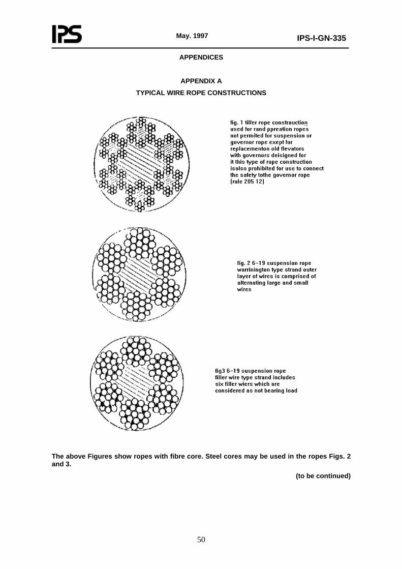
May. 1997
IPS-I-GN-335
50
APPENDICES
APPENDIX A
TYPICAL WIRE ROPE CONSTRUCTIONS
The above Figures show ropes with fibre core. Steel cores may be used in the ropes Figs. 2 and 3.
(to be continued)
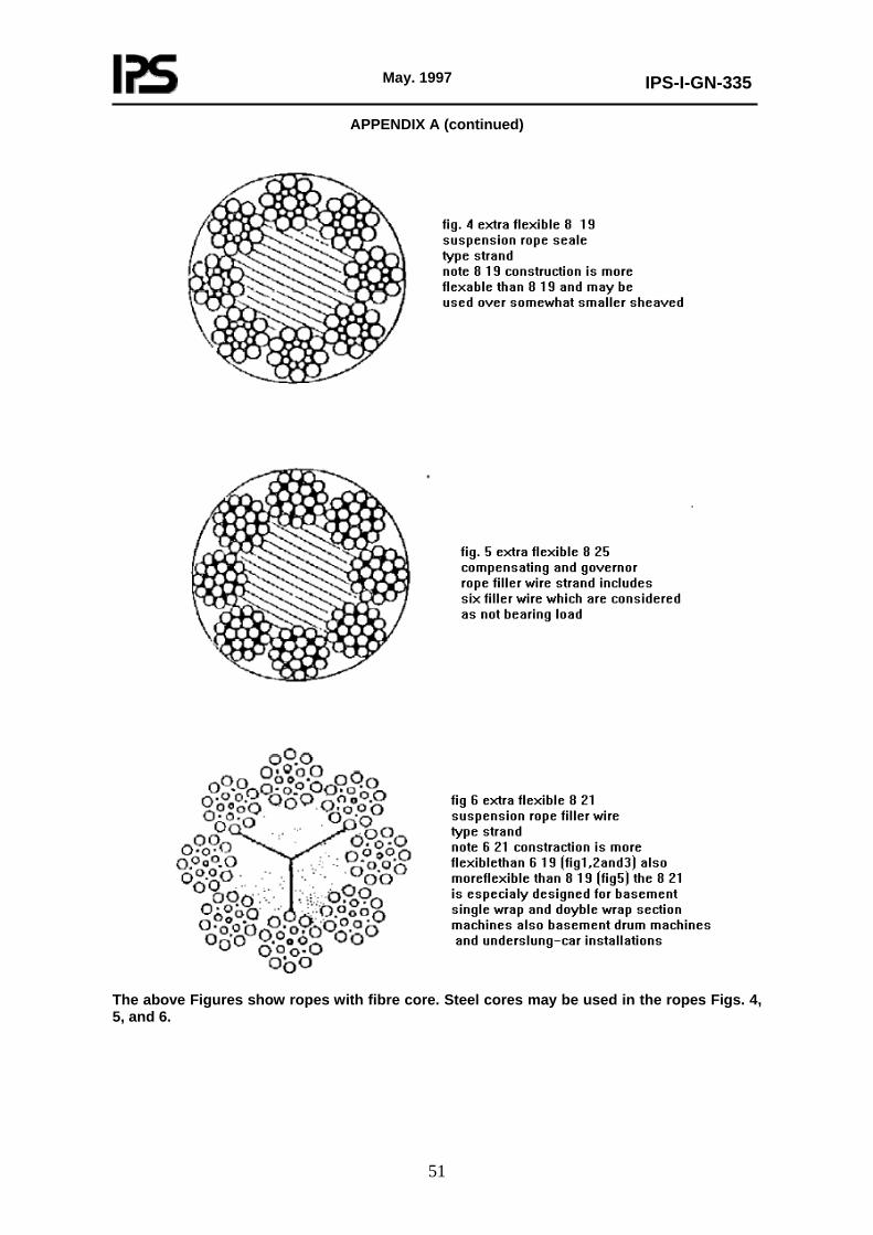
May. 1997
IPS-I-GN-335
51
APPENDIX A (continued)
The above Figures show ropes with fibre core. Steel cores may be used in the ropes Figs. 4, 5, and 6.
May. 1997
IPS-I-GN-335
52
APPENDIX B
DESCRIPTIONS AND SCHEMATIC LAYOUTS OF VARIOUS TYPES OF SAFETIES AND GOVERNORS
B.1 Introduction
B.1.1 Descriptions
The descriptions of these safeties cover only the more commonly used types. Obviously, it is impossible to include all of the varieties and modifications of such devices that have been designed or manufactured. An attempt has been made to include the types that are now being manufactured or were manufactured in considerable quantities in the past.
The schematic layouts are not mechanical drawings nor are they intended to be pictures of the actual devices, but rather very much simplified diagrams of vital operating parts.
B.1.2 Force-Travel diagrams
The force-travel diagram shown with each description is intended to show the general relationship between the retarding force applied to the guide rails and the travel of the car or counterweight after the governor operates.
These diagrams are not drawn to scale nor is the final force in any particular case to be considered as comparable with that in other diagrams. Some attempt has been made to indicate the relative travel of the car or counterweight subsequent to the governor operation before the retarding force is applied to the guide rails.
These force-travel diagrams are presented, along with the schematic layouts, descriptions, and notes, to assist in visualizing the various types of safeties and their methods of functioning.
B.2 Description and Schematic Layout of Safeties
Type A: Instantaneous Safety
Roller Operated and Eccentric Operated
Instantaneous safety (Type A) is a safety designed to apply a high retarding force as soon as it is brought into action. It
generally consists of:
(A) A roller normally located in a pocket but operating between a sloping surface and the guide rail; or
(B) an eccentric member pivoted on the car or counterweight structure and brought into contact with the guide rail surfaces. Once the eccentric or roller is in contact with the guide rail, this device is self-actuated by the operating force being derived from the mass and motion of the car or counterweight. The governor rope acts only to bring the roller or eccentric into contact with the guide rail. It is frequently designed to be applied by the inertia of the governor rigging.
Governor
The safety is generally applied by a centrifugal (bail type) governor with or without provision for pull-through but it is sometimes operated by a flyball governor. Its application by means of springs
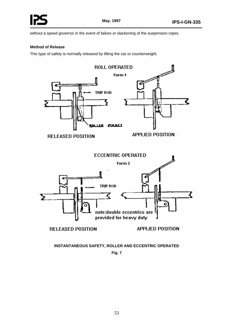
May. 1997
IPS-I-GN-335
53
without a speed governor in the event of failure or slackening of the suspension ropes.
Method of Release
This type of safety is normally released by lifting the car or counterweight.
INSTANTANEOUS SAFETY, ROLLER AND ECCENTRIC OPERATED
Fig. 7

May. 1997
IPS-I-GN-335
54
FORCE-TRAVEL DIAGRAM, INSTANTANEOUS SAFETY
Fig. 8
WEDGE CLAMP, DRUM-OPERATED SAFETY
Fig. 9
Type B: Wedge Clamp Safety
Wedge-Clamp Safety (W.C.) is one in which a wedge is driven between two pivoted members, the opposite ends of which form or carry the guide rail gripping surfaces. Travel of the wedge increases the pressure on the jaws. No elastic member is provided in the jaw assembly but one may be provided in the actuating mechanism.
Drum Operated
This is a device in which the wedges are normally operated by a rotation of right-hand and left-hand screws working within a drum on which a wire rope, attached to the governor rope, is wound.
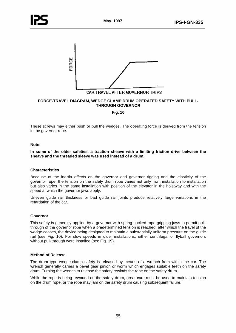
May. 1997
IPS-I-GN-335
55
FORCE-TRAVEL DIAGRAM, WEDGE CLAMP DRUM OPERATED SAFETY WITH PULL-
THROUGH GOVERNOR
Fig. 10
These screws may either push or pull the wedges. The operating force is derived from the tension in the governor rope.
Note:
In some of the older safeties, a traction sheave with a limiting friction drive between the sheave and the threaded sleeve was used instead of a drum.
Characteristics
Because of the inertia effects on the governor and governor rigging and the elasticity of the governor rope, the tension on the safety drum rope varies not only from installation to installation but also varies in the same installation with position of the elevator in the hoistway and with the speed at which the governor jaws apply.
Uneven guide rail thickness or bad guide rail joints produce relatively large variations in the retardation of the car.
Governor
This safety is generally applied by a governor with spring-backed rope-gripping jaws to permit pull-through of the governor rope when a predetermined tension is reached, after which the travel of the wedge ceases, the device being designed to maintain a substantially uniform pressure on the guide rail (see Fig. 10). For slow speeds in older installations, either centrifugal or flyball governors without pull-through were installed (see Fig. 19).
Method of Release
The drum type wedge-clamp safety is released by means of a wrench from within the car. The wrench generally carries a bevel gear pinion or worm which engages suitable teeth on the safety drum. Turning the wrench to release the safety rewinds the rope on the safety drum.
While the rope is being rewound on the safety drum, great care must be used to maintain tension on the drum rope, or the rope may jam on the safety drum causing subsequent failure.
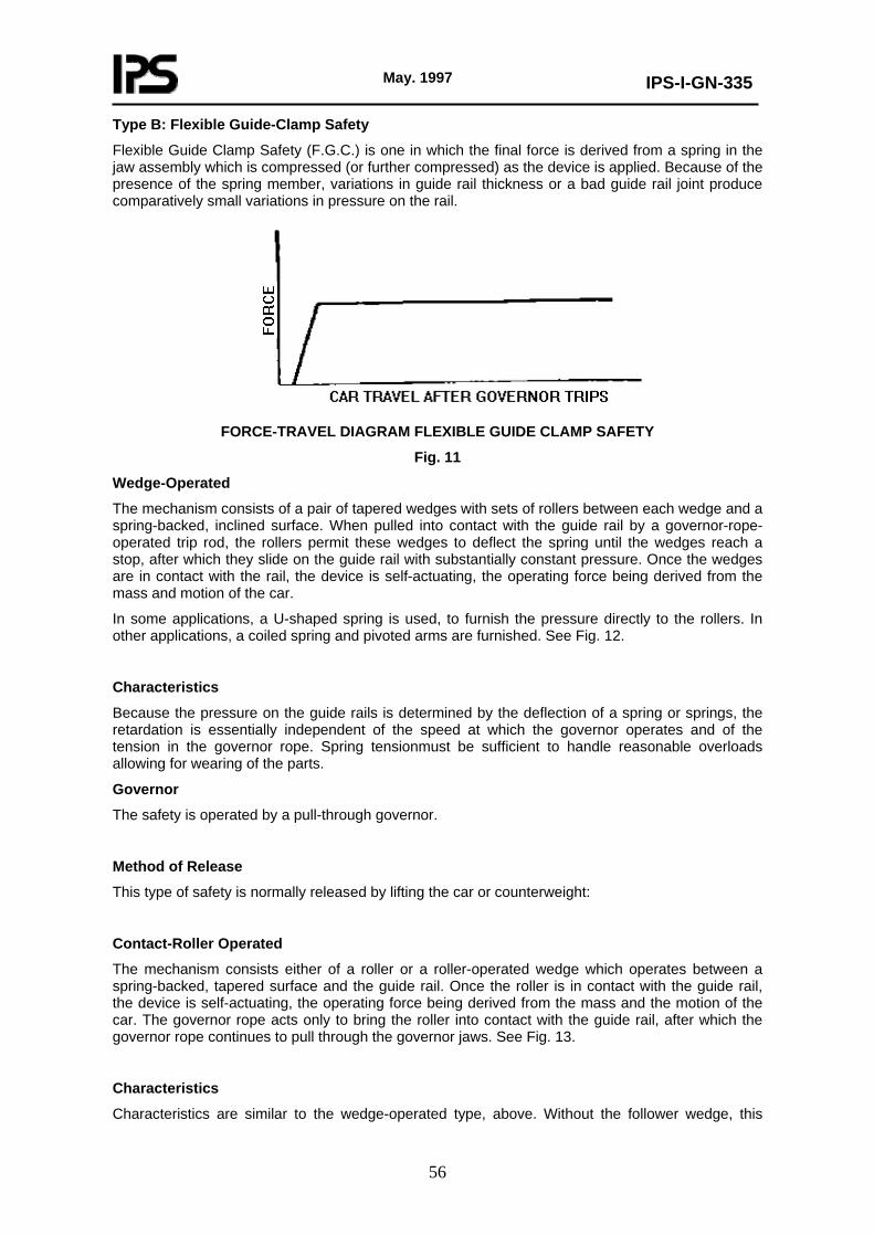
May. 1997
IPS-I-GN-335
56
Type B: Flexible Guide-Clamp Safety
Flexible Guide Clamp Safety (F.G.C.) is one in which the final force is derived from a spring in the jaw assembly which is compressed (or further compressed) as the device is applied. Because of the presence of the spring member, variations in guide rail thickness or a bad guide rail joint produce comparatively small variations in pressure on the rail.
FORCE-TRAVEL DIAGRAM FLEXIBLE GUIDE CLAMP SAFETY
Fig. 11
Wedge-Operated
The mechanism consists of a pair of tapered wedges with sets of rollers between each wedge and a spring-backed, inclined surface. When pulled into contact with the guide rail by a governor-rope-operated trip rod, the rollers permit these wedges to deflect the spring until the wedges reach a stop, after which they slide on the guide rail with substantially constant pressure. Once the wedges are in contact with the rail, the device is self-actuating, the operating force being derived from the mass and motion of the car.
In some applications, a U-shaped spring is used, to furnish the pressure directly to the rollers. In other applications, a coiled spring and pivoted arms are furnished. See Fig. 12.
Characteristics
Because the pressure on the guide rails is determined by the deflection of a spring or springs, the retardation is essentially independent of the speed at which the governor operates and of the tension in the governor rope. Spring tensionmust be sufficient to handle reasonable overloads allowing for wearing of the parts.
Governor
The safety is operated by a pull-through governor.
Method of Release
This type of safety is normally released by lifting the car or counterweight:
Contact-Roller Operated
The mechanism consists either of a roller or a roller-operated wedge which operates between a spring-backed, tapered surface and the guide rail. Once the roller is in contact with the guide rail, the device is self-actuating, the operating force being derived from the mass and the motion of the car. The governor rope acts only to bring the roller into contact with the guide rail, after which the governor rope continues to pull through the governor jaws. See Fig. 13.
Characteristics
Characteristics are similar to the wedge-operated type, above. Without the follower wedge, this

May. 1997
IPS-I-GN-335
57
safety tends to produce high retardation rates with a lightly loaded car.
Governor
The safety is operated by a pull-through governor.
Method of Release
To release a car safety, a lever wrench inserted into a slot in the car floor is used to compress and then reset the spring.
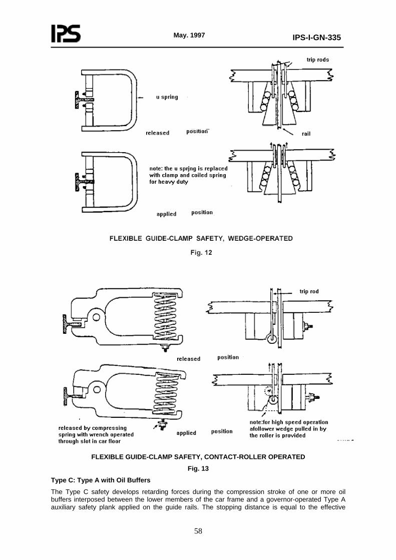
May. 1997
IPS-I-GN-335
58
FLEXIBLE GUIDE-CLAMP SAFETY, CONTACT-ROLLER OPERATED
Fig. 13
Type C: Type A with Oil Buffers
The Type C safety develops retarding forces during the compression stroke of one or more oil buffers interposed between the lower members of the car frame and a governor-operated Type A auxiliary safety plank applied on the guide rails. The stopping distance is equal to the effective
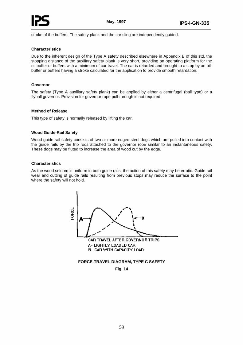
May. 1997
IPS-I-GN-335
59
stroke of the buffers. The safety plank and the car sling are independently guided.
Characteristics
Due to the inherent design of the Type A safety described elsewhere in Appendix B of this std. the stopping distance of the auxiliary safety plank is very short, providing an operating platform for the oil buffer or buffers with a minimum of car travel. The car is retarded and brought to a stop by an oil-buffer or buffers having a stroke calculated for the application to provide smooth retardation.
Governor
The safety (Type A auxiliary safety plank) can be applied by either a centrifugal (bail type) or a flyball governor. Provision for governor rope pull-through is not required.
Method of Release
This type of safety is normally released by lifting the car.
Wood Guide-Rail Safety
Wood guide-rail safety consists of two or more edged steel dogs which are pulled into contact with the guide rails by the trip rods attached to the governor rope similar to an instantaneous safety. These dogs may be fluted to increase the area of wood cut by the edge.
Characteristics
As the wood seldom is uniform in both guide rails, the action of this safety may be erratic. Guide rail wear and cutting of guide rails resulting from previous stops may reduce the surface to the point where the safety will not hold.
FORCE-TRAVEL DIAGRAM, TYPE C SAFETY
Fig. 14
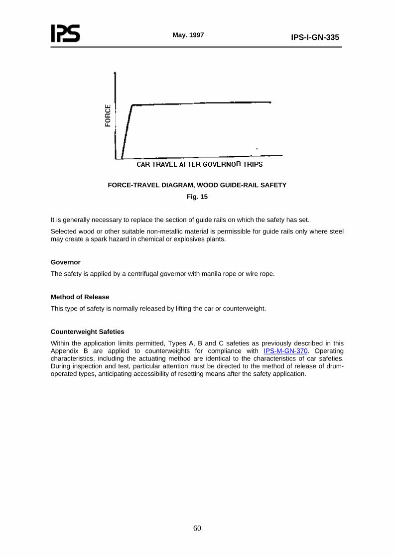
May. 1997
IPS-I-GN-335
60
FORCE-TRAVEL DIAGRAM, WOOD GUIDE-RAIL SAFETY
Fig. 15
It is generally necessary to replace the section of guide rails on which the safety has set.
Selected wood or other suitable non-metallic material is permissible for guide rails only where steel may create a spark hazard in chemical or explosives plants.
Governor
The safety is applied by a centrifugal governor with manila rope or wire rope.
Method of Release
This type of safety is normally released by lifting the car or counterweight.
Counterweight Safeties
Within the application limits permitted, Types A, B and C safeties as previously described in this Appendix B are applied to counterweights for compliance with IPS-M-GN-370. Operating characteristics, including the actuating method are identical to the characteristics of car safeties. During inspection and test, particular attention must be directed to the method of release of drum-operated types, anticipating accessibility of resetting means after the safety application.
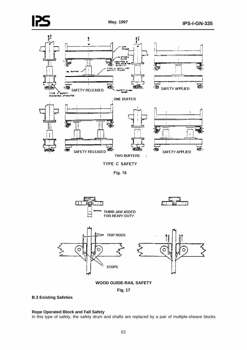
May. 1997
IPS-I-GN-335
61
WOOD GUIDE-RAIL SAFETY
Fig. 17
B.3 Existing Safeties
Rope Operated Block and Fall Safety In this type of safety, the safety drum and shafts are replaced by a pair of multiple-sheave blocks

May. 1997
IPS-I-GN-335
62
over which the safety rope is revved. In operation, the tension in the governor rope draws these blocks together, pulling the wedges to which they are attached into action. The operating force is derived from the tension in the governor rope. The multiple sheave arrangement requires a disproportionately long governor rope movement to engage the safety jaws with the guide rails. Characteristics Characteristics are the same as for the drum-type wedge clamp. Governor The safety is operated by a governor usually without provision for pull-through. (Not permitted by IPS-M-GN-370). Method of Release Released by operating a lever between parallel bars in a member attached to one set of blocks and engaging lugs or bosses on a member attached to the other set.
FORCE-TRAVEL DIAGRAM, DRUM AND BLOCK-AND-FALL SAFETY, WITHOUT PULL-
THROUGH Fig. 18
WEDGE CLAMP, BLOCK-AND-FALL SAFETY
Fig. 19
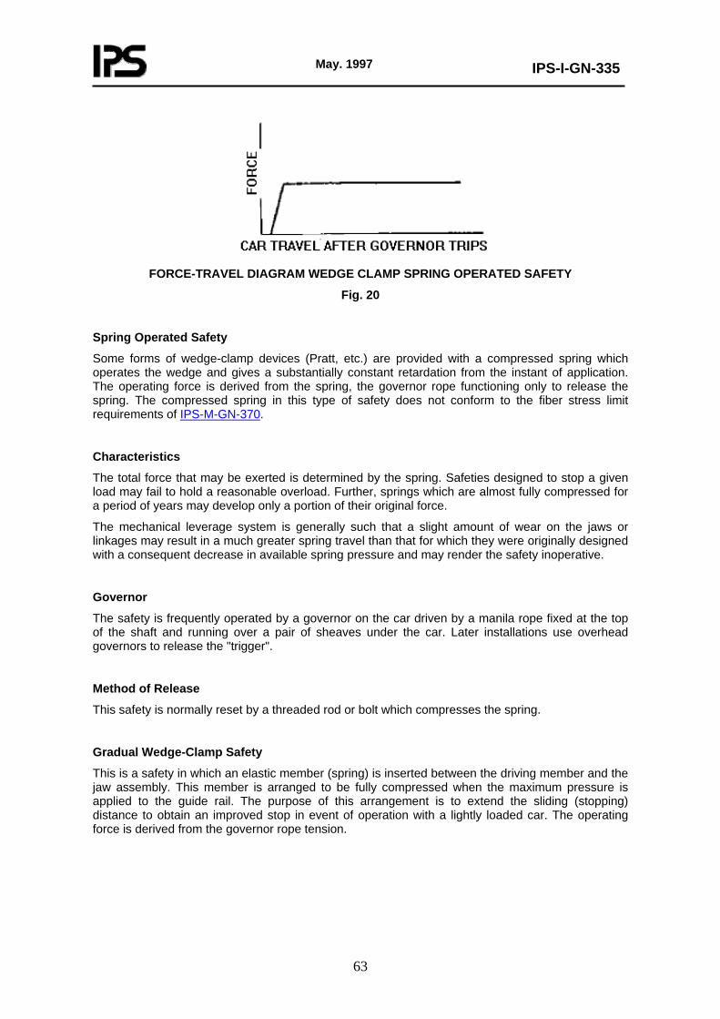
May. 1997
IPS-I-GN-335
63
FORCE-TRAVEL DIAGRAM WEDGE CLAMP SPRING OPERATED SAFETY
Fig. 20
Spring Operated Safety
Some forms of wedge-clamp devices (Pratt, etc.) are provided with a compressed spring which operates the wedge and gives a substantially constant retardation from the instant of application. The operating force is derived from the spring, the governor rope functioning only to release the spring. The compressed spring in this type of safety does not conform to the fiber stress limit requirements of IPS-M-GN-370.
Characteristics
The total force that may be exerted is determined by the spring. Safeties designed to stop a given load may fail to hold a reasonable overload. Further, springs which are almost fully compressed for a period of years may develop only a portion of their original force.
The mechanical leverage system is generally such that a slight amount of wear on the jaws or linkages may result in a much greater spring travel than that for which they were originally designed with a consequent decrease in available spring pressure and may render the safety inoperative.
Governor
The safety is frequently operated by a governor on the car driven by a manila rope fixed at the top of the shaft and running over a pair of sheaves under the car. Later installations use overhead governors to release the "trigger".
Method of Release
This safety is normally reset by a threaded rod or bolt which compresses the spring.
Gradual Wedge-Clamp Safety
This is a safety in which an elastic member (spring) is inserted between the driving member and the jaw assembly. This member is arranged to be fully compressed when the maximum pressure is applied to the guide rail. The purpose of this arrangement is to extend the sliding (stopping) distance to obtain an improved stop in event of operation with a lightly loaded car. The operating force is derived from the governor rope tension.
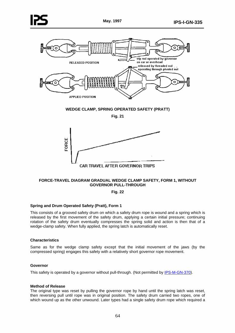
May. 1997
IPS-I-GN-335
64
WEDGE CLAMP, SPRING OPERATED SAFETY (PRATT)
Fig. 21
FORCE-TRAVEL DIAGRAM GRADUAL WEDGE CLAMP SAFETY, FORM 1, WITHOUT
GOVERNOR PULL-THROUGH
Fig. 22
Spring and Drum Operated Safety (Pratt), Form 1
This consists of a grooved safety drum on which a safety drum rope is wound and a spring which is released by the first movement of the safety drum, applying a certain initial pressure; continuing rotation of the safety drum eventually compresses the spring solid and action is then that of a wedge-clamp safety. When fully applied, the spring latch is automatically reset.
Characteristics
Same as for the wedge clamp safety except that the initial movement of the jaws (by the compressed spring) engages this safety with a relatively short governor rope movement.
Governor
This safety is operated by a governor without pull-through. (Not permitted by IPS-M-GN-370).
Method of Release The original type was reset by pulling the governor rope by hand until the spring latch was reset, then reversing pull until rope was in original position. The safety drum carried two ropes, one of which wound up as the other unwound. Later types had a single safety drum rope which required a

May. 1997
IPS-I-GN-335
65
wrench in the car for resetting. Drum (Internal Spring) Operated Safety, Form 2 This consists of a grooved safety drum on which the safety drum rope is wound, a spring located within the safety drum and a pair of sleeves having a triple-pitch thread on the outside and a single-pitch thread on the inside. Both sets of threads are right-hand on one sleeve and left-hand on the other. The triple-pitch threads operate within the drum and the single-pitch threads carry the usual push rods operating the wedges. In operation, the first revolution of the drum advances the sleeves taking up the jaw clearance, after which the motion of the sleeves stops, further rotation of the drum advancing the wedges by means of the single-pitch screws and compresses the spring until it is solid, after which the action is that of a standard wedge-clamp safety. Characteristics Same as for wedge-clamp safety except that it gives a relatively longer slide with light loads and low governor-tripping speeds than does standard wedge clamp safety. Governor Generally without pull-through but pull-through type may be employed. Method of Release Safety is released by means of a wrench which is used from within the car to rewind the safety drum.
GRADUAL WEDGE CLAMP SPRING AND DRUM SAFETY (PRATT), FORM 1
Fig. 23
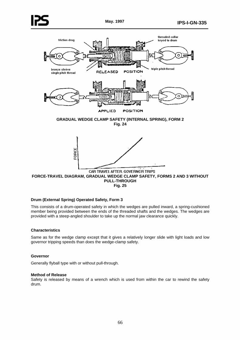
May. 1997
IPS-I-GN-335
66
GRADUAL WEDGE CLAMP SAFETY (INTERNAL SPRING), FORM 2
Fig. 24
FORCE-TRAVEL DIAGRAM, GRADUAL WEDGE CLAMP SAFETY, FORMS 2 AND 3 WITHOUT
PULL-THROUGH Fig. 25
Drum (External Spring) Operated Safety, Form 3
This consists of a drum-operated safety in which the wedges are pulled inward, a spring-cushioned member being provided between the ends of the threaded shafts and the wedges. The wedges are provided with a steep-angled shoulder to take up the normal jaw clearance quickly.
Characteristics
Same as for the wedge clamp except that it gives a relatively longer slide with light loads and low governor tripping speeds than does the wedge-clamp safety.
Governor
Generally flyball type with or without pull-through.
Method of Release Safety is released by means of a wrench which is used from within the car to rewind the safety drum.
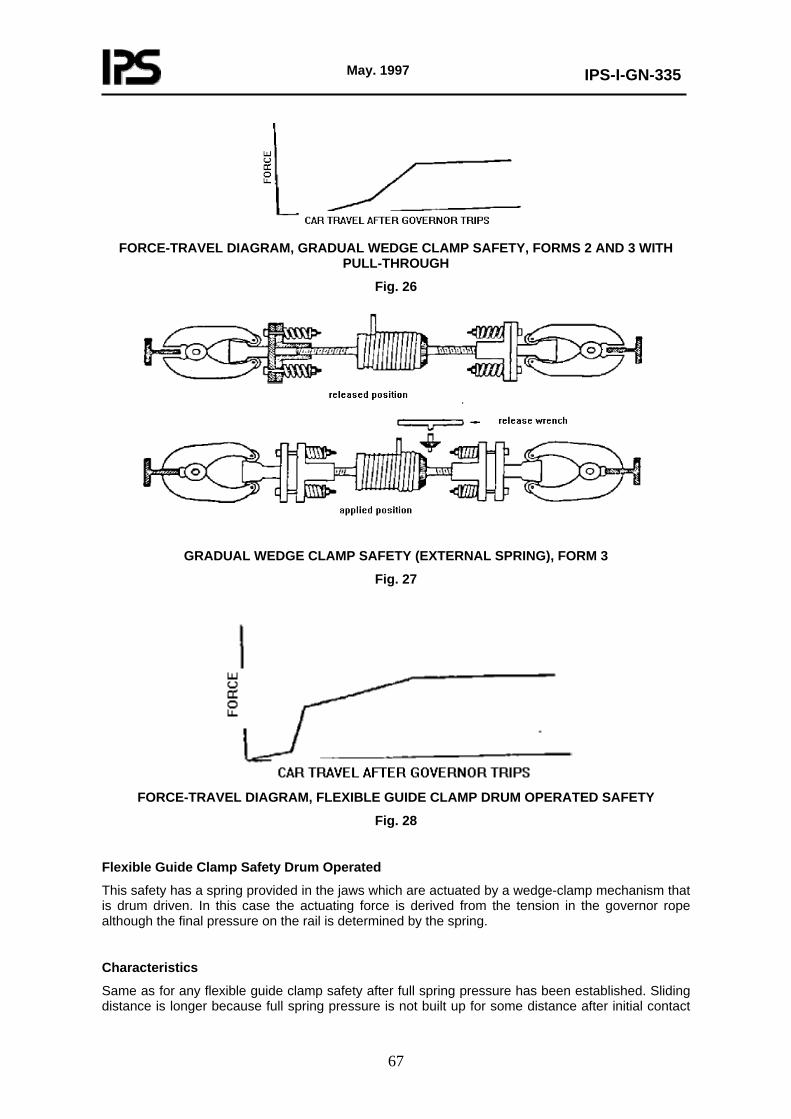
May. 1997
IPS-I-GN-335
67
FORCE-TRAVEL DIAGRAM, GRADUAL WEDGE CLAMP SAFETY, FORMS 2 AND 3 WITH
PULL-THROUGH
Fig. 26
GRADUAL WEDGE CLAMP SAFETY (EXTERNAL SPRING), FORM 3
Fig. 27
FORCE-TRAVEL DIAGRAM, FLEXIBLE GUIDE CLAMP DRUM OPERATED SAFETY
Fig. 28
Flexible Guide Clamp Safety Drum Operated
This safety has a spring provided in the jaws which are actuated by a wedge-clamp mechanism that is drum driven. In this case the actuating force is derived from the tension in the governor rope although the final pressure on the rail is determined by the spring.
Characteristics
Same as for any flexible guide clamp safety after full spring pressure has been established. Sliding distance is longer because full spring pressure is not built up for some distance after initial contact
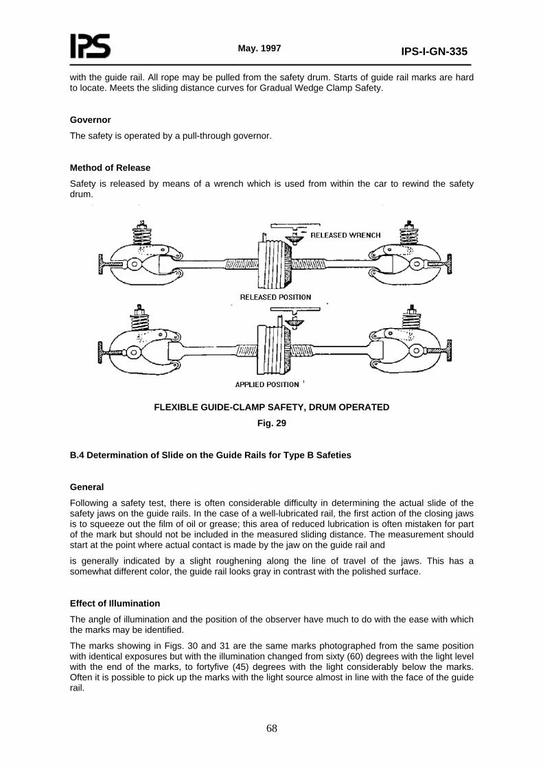
May. 1997
IPS-I-GN-335
68
with the guide rail. All rope may be pulled from the safety drum. Starts of guide rail marks are hard to locate. Meets the sliding distance curves for Gradual Wedge Clamp Safety.
Governor
The safety is operated by a pull-through governor.
Method of Release
Safety is released by means of a wrench which is used from within the car to rewind the safety drum.
FLEXIBLE GUIDE-CLAMP SAFETY, DRUM OPERATED
Fig. 29
B.4 Determination of Slide on the Guide Rails for Type B Safeties
General
Following a safety test, there is often considerable difficulty in determining the actual slide of the safety jaws on the guide rails. In the case of a well-lubricated rail, the first action of the closing jaws is to squeeze out the film of oil or grease; this area of reduced lubrication is often mistaken for part of the mark but should not be included in the measured sliding distance. The measurement should start at the point where actual contact is made by the jaw on the guide rail and
is generally indicated by a slight roughening along the line of travel of the jaws. This has a somewhat different color, the guide rail looks gray in contrast with the polished surface.
Effect of Illumination
The angle of illumination and the position of the observer have much to do with the ease with which the marks may be identified.
The marks showing in Figs. 30 and 31 are the same marks photographed from the same position with identical exposures but with the illumination changed from sixty (60) degrees with the light level with the end of the marks, to fortyfive (45) degrees with the light considerably below the marks. Often it is possible to pick up the marks with the light source almost in line with the face of the guide rail.

May. 1997
IPS-I-GN-335
69
Marks on Dry Guide Rails
When the guide rail is dry, as is the case with roller guides, the mark may be very difficult to determine as there is no disturbed film of lubricant to aid in its location. However, by carefully adjusting the position of the light source and changing the angle of vision, it is generally possible to determine the point at which the mark starts.
Determination of Final Position of Jaws
As the jaws tend to bite more deeply into the guide rail after full application, even with types where the pressure of the jaws on the guide rail is designed to remain constant, there is little difficulty, as a rule, in determining the final position of the jaws. Where the guide rails are lubricated, the terminal mark may generally be indicated by the piling up of oil or grease below the safety shoe; frequently the entire "print" of the shoe or gib may be on the guide rail in the final stop position.
Interrupted Marks
It occasionally happens that the safety jaws will come in contact with the guide rail and leave a mark for a certain distance, and then the mark will be lost for a distance of 30 mm to 100 mm or perhaps 300 mm. This may be due to several causes, among them slight deviations in the alignment of the guide rails, variations in thickness, or the sudden engagement of the governor rope by the governor, with a following jump of the governor rope which will permit the jaws to clear for a small fraction of a second. In no case should these preliminary marks be considered in the measurement of the slide. The slide should be measured from the highest point of the continuous marking only.
Measurements
Stopping distance should be determined by measuring the length of the marks made by the safety on both sides of each guide rail, deducting the length of the safety jaw or wedge, and taking the average of the four measurements.
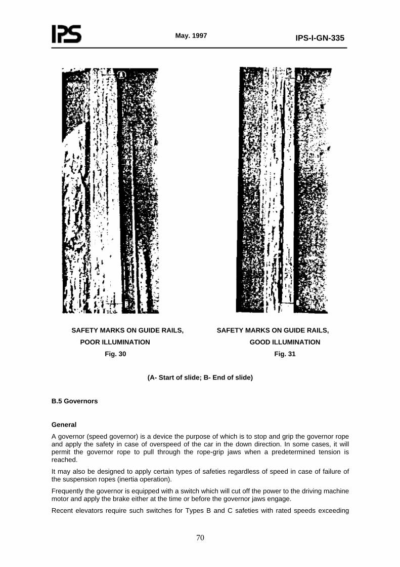
May. 1997
IPS-I-GN-335
70
SAFETY MARKS ON GUIDE RAILS, SAFETY MARKS ON GUIDE RAILS,
POOR ILLUMINATION GOOD ILLUMINATION
Fig. 30 Fig. 31
(A- Start of slide; B- End of slide)
B.5 Governors
General
A governor (speed governor) is a device the purpose of which is to stop and grip the governor rope and apply the safety in case of overspeed of the car in the down direction. In some cases, it will permit the governor rope to pull through the rope-grip jaws when a predetermined tension is reached.
It may also be designed to apply certain types of safeties regardless of speed in case of failure of the suspension ropes (inertia operation).
Frequently the governor is equipped with a switch which will cut off the power to the driving machine motor and apply the brake either at the time or before the governor jaws engage.
Recent elevators require such switches for Types B and C safeties with rated speeds exceeding

May. 1997
IPS-I-GN-335
71
0.750 m/s. These switches provide protection against overspeed in either direction. A second set of contacts may be provided to regulate the speed of the motor. At times, and additional set of contacts may be provided to limit speed when approaching terminal landings.
Governor Types
Flyball Governor
A flyball governor is one operated by a pair of flyballs attached to, and driven by, a vertical shaft. Links attached to the flyball arms lift a collar or sleeve operating against an adjustable compression spring on the shaft. The vertical shaft is driven through a pair of bevel gears by a sheave which in turn is driven by the governor rope attached to the car. Various gear ratios are generally available to take care of various tripping speeds. When a predetermined speed is reached, the collar is lifted far enough to trip the rope grips, which in older elevators may consist of a pair of grooved arcs pivoted on opposite sides of the down running side of the governor rope. See Paragraph B 6 in this Appendix for a full description of governor jaws. These jaws grip and stop the rope when they are tripped. Gear teeth are provided to insure equal travel of the jaws. Where pull-through is desired, one of the rope grips is spring backed.
Overhead Flyball
This is a modification of the usual flyball type, the flyballs being mounted with the point of support below the plane of rotation. When at rest, the flyballs lie inside the lines through their supports.
A disc lifted by a pair of levers attached to the ball arms trips the rope grip. Because the outward travel of the balls is aided by gravity, smaller masses may be used.
Horizontal-Shaft Governor
A horizontal-shaft governor is one with a shaft perpendicular to the plane of the sheave. Pivoted masses, spring controlled, operate a lift rod by means of short arms attached to the masses. By varying the tension of the springs, a considerable range of speeds may be covered.
Centrifugal Governor
A centrifugal governor (disc governor, bail-type governor, knock-out governor) consists of a sheave containing of a sheave containing two or more eccentrically pivoted weights normally held by springs within the periphery of the sheave, a bail or arm carrying a wedge in line with a governor rope, the bail being mounted eccentrically to the sheave. When the speed of the governor rope reaches a predetermined value, the weights are driven outwared by the centrifugal force until the bail or arm is engaged and moved in the direction of rotation until the wedge member engages the rope and locks it against the sheave.
Ordinarily, this type of governor has no provision for pull-through, but when used for moderate and high speeds, it is arranged with parallel spring-backed jaws which permits pull-through. Jaw-grips are tripped by a link connecting them to a notched disc, normally stationary, which is operated on overspeed by a dog or lug on the inner end of either of the pivoted weights.
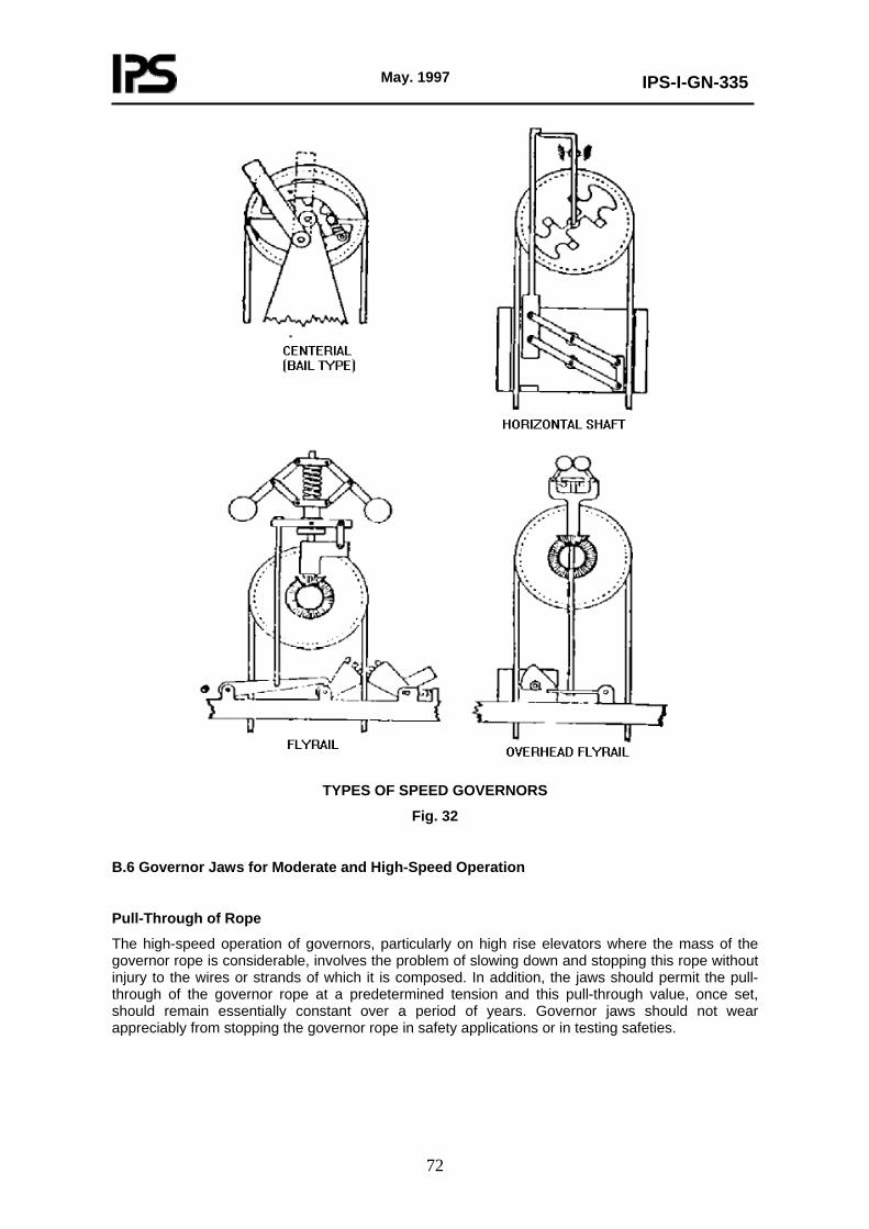
May. 1997
IPS-I-GN-335
72
TYPES OF SPEED GOVERNORS
Fig. 32
B.6 Governor Jaws for Moderate and High-Speed Operation
Pull-Through of Rope
The high-speed operation of governors, particularly on high rise elevators where the mass of the governor rope is considerable, involves the problem of slowing down and stopping this rope without injury to the wires or strands of which it is composed. In addition, the jaws should permit the pull-through of the governor rope at a predetermined tension and this pull-through value, once set, should remain essentially constant over a period of years. Governor jaws should not wear appreciably from stopping the governor rope in safety applications or in testing safeties.
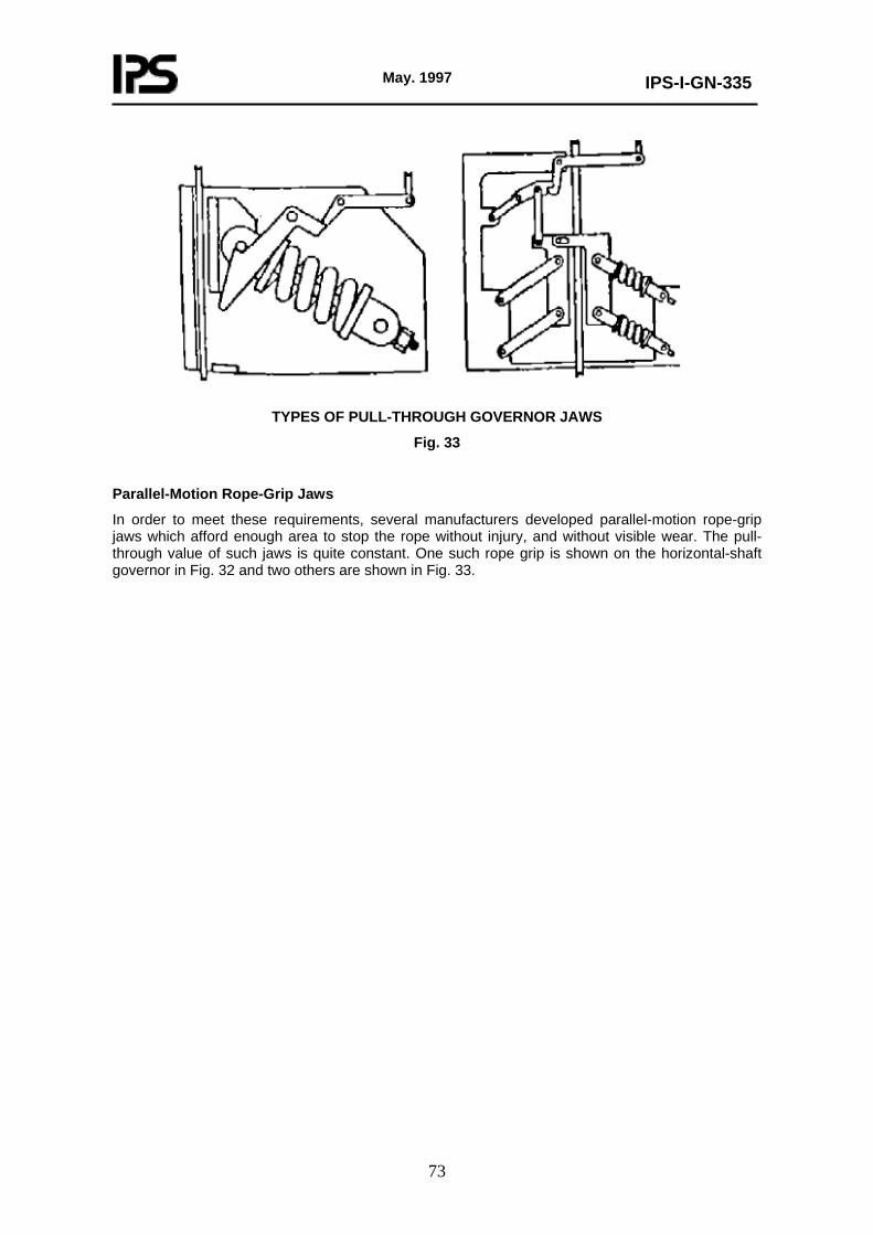
May. 1997
IPS-I-GN-335
73
TYPES OF PULL-THROUGH GOVERNOR JAWS
Fig. 33
Parallel-Motion Rope-Grip Jaws
In order to meet these requirements, several manufacturers developed parallel-motion rope-grip jaws which afford enough area to stop the rope without injury, and without visible wear. The pull-through value of such jaws is quite constant. One such rope grip is shown on the horizontal-shaft governor in Fig. 32 and two others are shown in Fig. 33.
May. 1997
IPS-I-GN-335
74
APPENDIX C
HANDLING AND SOCKETING OF WIRE ROPE
C.1 Handling, Unreeling, and Uncoiling of Wire Rope
Storage
Stocks of rope should be stored in a cool, dry location which is reasonably free from dust and dirt. If wrapped in paper or burlap, the wrappings should not be removed before the rope is to be used, unless they have become wet in transit, in which case, the wrappings should be removed and the rope dried. Ropes should always be provided with protection from the weather. If stored in a building under construction, protect the rope from sand, lime, plaster and mortar.
Protection During Unreeling and Cutting
Before pulling out lengths of wire rope, be sure that the space to be used is clean-free from sand, lime, dirt or cement dust. Where corridors or hallways are used, sweep the floor thoroughly before pulling out a length of rope. Never pull out rope over earth, sand, or mortar piles. If it is necessary to pull ropes from reels or coils out-doors, select an area covered by sod, avoiding all bare spots.
Rope Lengths When Reroping
When reroping, the new rope is generally cut somewhat shorter than the rope which it replaces. This is done to take care of part of the stretch which will develop during the life of the rope (generally about one percent of the length). However, in the case of very short ropes, it will not be possible to allow for this entire stretch without decreasing the overhead clearance of the car and counterweight to a dangerous extent. Many serious accidents have resulted from the installation of new ropes which were cut too short. Check the clearances before the rope is cut. Be sure that the rope lengths are identical so that it will not be necessary to use part of the shackle rod adjustment to equalize ropes at the time of installation.
Handling
Wire rope should be handled carefully so that it is not twisted, untwisted, or kinked. The ultimate strength of a wire rope is dependent upon the combined strength of the individual wires. If the position of the wires in the strands of the rope as manufactured is disturbed, the rope may not develop is ultimate strength when a load is applied. Kinks in a rope damage the wires and for that reason, a kinked rope will not give the service normally expected.
Method of Unreeling and Uncoiling
If a wire rope is not properly unwound from a reel, the rope may be kinked, twisted, or untwisted. The rope should be pulled off the reel or uncoiled in a straight line. To do this, one of the following three methods may be used:
a) The reel may be mounted on a horizontal shaft supported by two jacks and the rope is pulled from the reel by a man holding the free end of the rope, walking away in a straight line from the reel which revolves as the rope unwinds. A board held against the flange of the reel as a brake will prevent the reel turning too fast and resulting in a loop falling over the flange of the reel which may cause a kink in the rope.
b) If method (a) cannot be used, the reel may be mounted on a vertical shaft or with the reel flange flat on a turntable and then unwound as described in method (a). When unreeling from a turntable, the wire rope is likely to drop over the bottom flange of the reel and be damaged if the rope is pulled around the turntable axle.
Damage to the rope can be avoided if, when a loop droops off the flange, pulling is stopped
May. 1997
IPS-I-GN-335
75
immediately and the loop replaced on the reel. Under no circumstances should the rope be thrown over the upper flange as such action may result in a kink, or in twisting or untwisting of the rope.
c) If the rope is coiled, the outer end of the rope should be released and the coil rolled along the floor or ground in a straight line. The coil should not be laid on the floor or ground and loops thrown off the coil and pulled out as the rope may be kinked and damaged as indicated above.
C.2 Socketing Wire Rope Using Tapered Rope Sockets
General
If wire ropes are properly seized socketed, the original and uniform relation of tension obtained by correct rope manufacture will not be disturbed and the socketed rope will develop from eighty (80) to one hundred (100) percent of the ultimate strength of the rope.
Design of Rope Sockets
The design of wire rope sockets should conform to the requirements of IPS-M-GN-370. Tapered babbitted sockets should in addition conform to the requirements of IPS-M-GN-370 with a basket length of not less than four and threequarters (4¾) times the rope diameter used and having a hole at the small end of the socket measuring between 1.58 mm and 4.74 mm larger than the rope diameter, depending on the diameter of the rope used.
Rope Seizing
The rope ends to be socketed should, before cutting, be served with seizings in accordance with the following (see Fig. 34):
a) The seizing should be done with annealed iron wire, provided that other methods of seizing may be used which give the same protection from loss of rope lay. Where iron wire is used for seizing, the length of each seizing should be not less than the diameter of the rope.
b) For nonpreformed rope, three (3) seizings should be made at each side of the cut in the rope. The first seizing should be close to the cut end of the rope and the second seizing should be spaced back from the first the length of the end of the rope to be turned in. The third seizing should be at a distance from the second equal to thelength of the tapered portion of the socket.
c) For preformed rope, one (1) seizing should be made at each side of the cut in the rope. The seizing should be at a distance from the end of the rope equal to the length of the tapered portion of the socket plus the length of the portion of the rope to be turned in.
d) If other types of seizing are used, they should be so installed as to not interfere with inspection of the socket. After the rope has been seized, it should be inserted into the socket through the hole in the small end a sufficient distance for manipulation; and where nonpreformed rope is used, the first two seizings should be removed. The rope strands should then be spread apart and the fibre core cut away as close as possible to the remaining seizing, where rope with fibre core is used (see Fig. 34).
Babbitted Sockets
While wire rope manufacturers universally advocate the use of zinc (spelter) for socketing wire rope and have developed a method of separating, straightening, and cleaning the individual wires, the difficulties of making a secure fastening in the field are so great that, without exception, elevator construction companies have used the turned-in strand, babbitt-poured socket, even though this may give a finished socket which may develop a slightly lower percentage of the strength of the
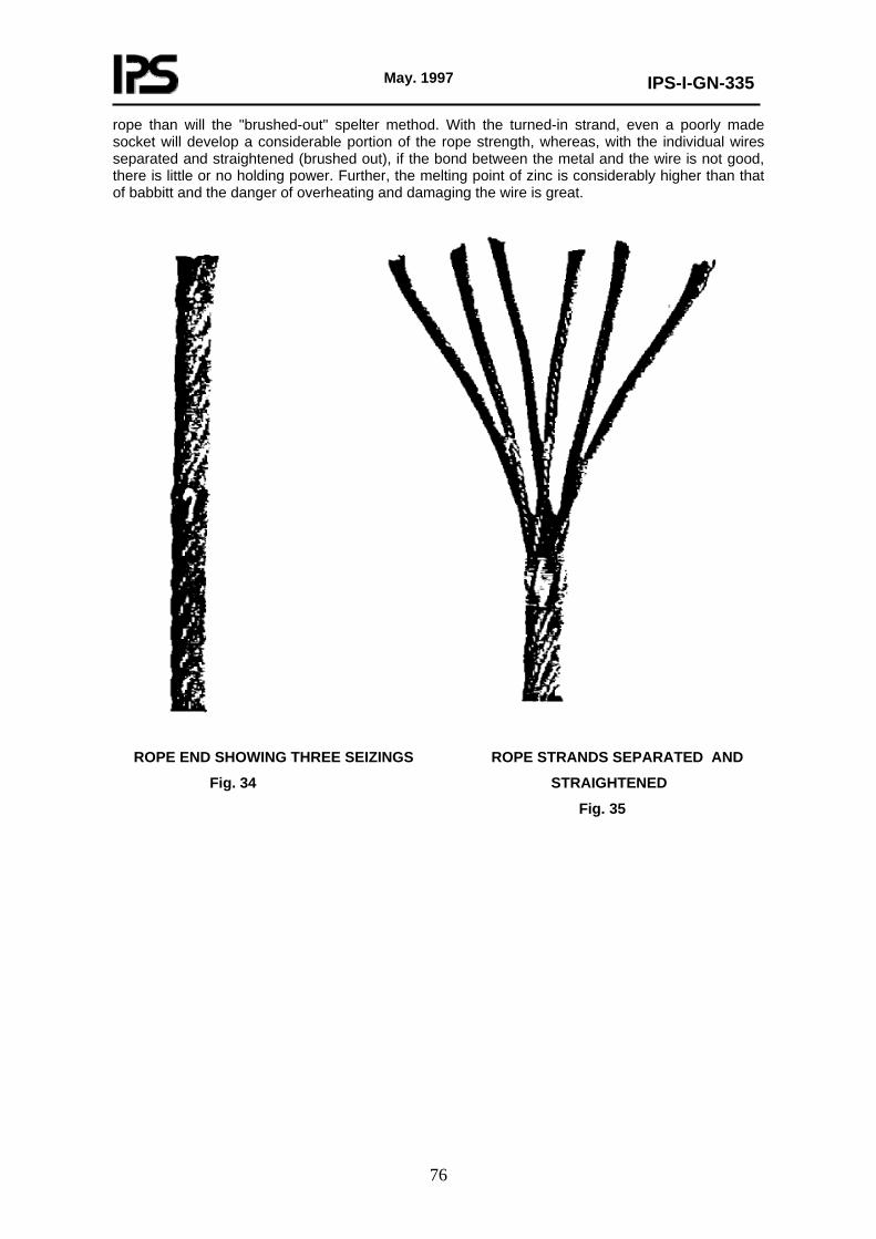
May. 1997
IPS-I-GN-335
76
rope than will the "brushed-out" spelter method. With the turned-in strand, even a poorly made socket will develop a considerable portion of the rope strength, whereas, with the individual wires separated and straightened (brushed out), if the bond between the metal and the wire is not good, there is little or no holding power. Further, the melting point of zinc is considerably higher than that of babbitt and the danger of overheating and damaging the wire is great.
ROPE END SHOWING THREE SEIZINGS ROPE STRANDS SEPARATED AND
Fig. 34 STRAIGHTENED
Fig. 35
May. 1997
IPS-I-GN-335
77
Removal of Grease or Oil
Grease and oil should be removed by cleaning the outer surface of the exposed rope strands with a nonflammable, lowtoxic solvent.
Note:
Certain elevator companies now omit this washing with solvent depending on the hot babbitt to burn off the lubricant. Tests of two sockets, one with the rope carefully cleaned, the other with the rope uncleaned, were made and both sockets gave more than the required eighty (80) percent of the strength of the rope. They were both poured at the same time from a pot of metal, the temperature of which was determined by the pine splinter test. The difference in strength was one and one half (1½) percent, the cleaned strands giving the slightly higher value.
Solvent vapors and fumes should not be inhaled and therefore adequate ventilation should be provided.
Turning in of Rope Strands
The exposed rope strands should then be bent, turned in and bunched closely together (see Fig. 36), each strand being turned back the same direction. The portion turned in should have a length of not less than two and one-half (2½) times the diameter of the rope and such that, when the rope is pulled as far as possible into the socket, the bend of the turnedin strands should be slightly over-flush with the mouth of the tapered socket (large end) and will be visible when the socket has babbitted, (see Fig. 37). Where rope with steel core is used, the steel core shall be cut off even with the tops of the looped strands.
The rope end should be pulled as far as possible into the socket so that the remaining seizing will then be entirely outside the small end of the socket to permit inspection of the wires just below the small end of the socket.
Position of Socket Preparatory to Pouring Babbitt
The socket should be held in a vertical position with the large end up, and the rope held in a position axial with the socket. Tape or waste may be wound around the rope at the small end of the socket to prevent the babbitt from seeping through, and after the metal has been cooled, it should be removed.
Babbitt Metal and Heating Before Pouring
The babbitt metal should contain at least nine (9) percent of antimony and be clean and free of dross.
The babbitt should be heated to a fluidity at a temperature just sufficient to char a piece of soft wood (such as white pine) without igniting it. Care should be taken not to overheat the babbitt sufficiently to damage the rope.
Caution
While heating and pouring the babbitt, the worker should wear either a face mask or suitable goggles to protect the eyes in case the babbitt should spatter.
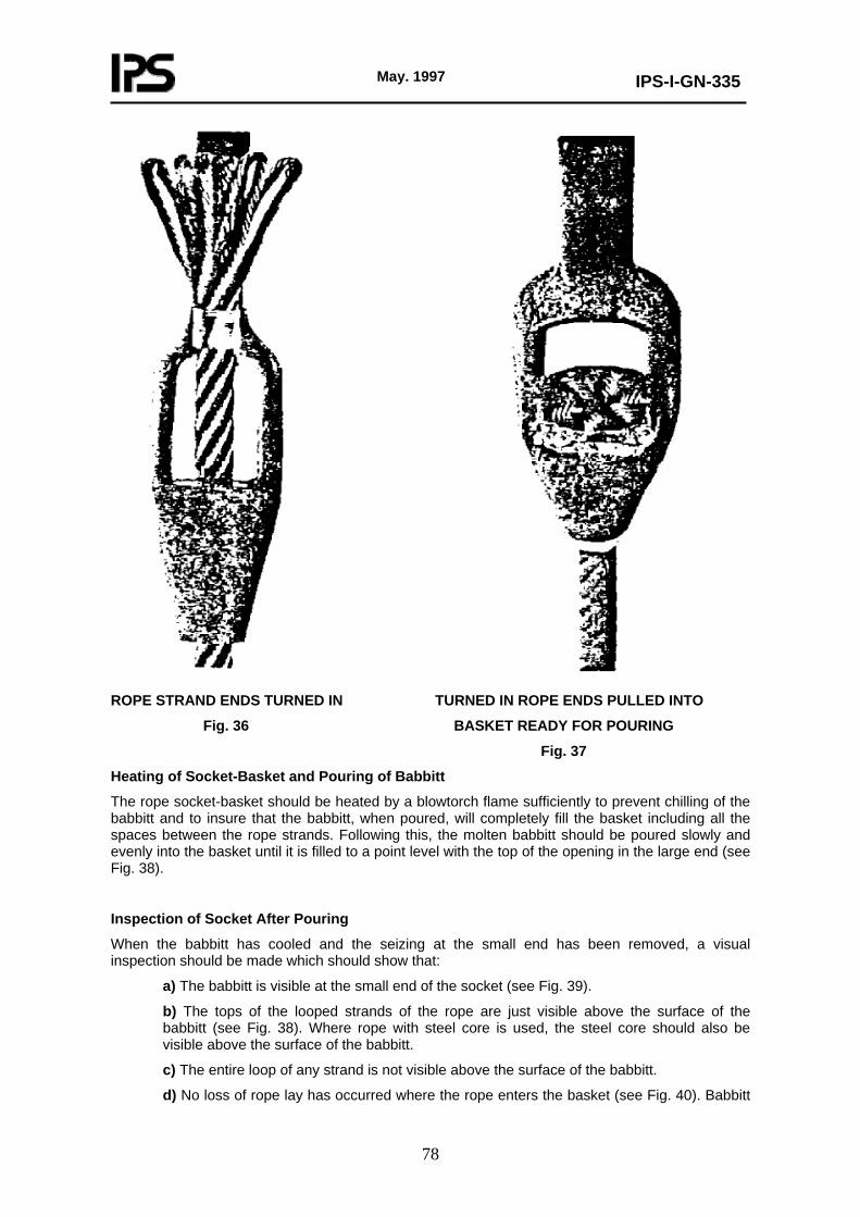
May. 1997
IPS-I-GN-335
78
ROPE STRAND ENDS TURNED IN TURNED IN ROPE ENDS PULLED INTO
Fig. 36 BASKET READY FOR POURING
Fig. 37
Heating of Socket-Basket and Pouring of Babbitt
The rope socket-basket should be heated by a blowtorch flame sufficiently to prevent chilling of the babbitt and to insure that the babbitt, when poured, will completely fill the basket including all the spaces between the rope strands. Following this, the molten babbitt should be poured slowly and evenly into the basket until it is filled to a point level with the top of the opening in the large end (see Fig. 38).
Inspection of Socket After Pouring
When the babbitt has cooled and the seizing at the small end has been removed, a visual inspection should be made which should show that:
a) The babbitt is visible at the small end of the socket (see Fig. 39).
b) The tops of the looped strands of the rope are just visible above the surface of the babbitt (see Fig. 38). Where rope with steel core is used, the steel core should also be visible above the surface of the babbitt.
c) The entire loop of any strand is not visible above the surface of the babbitt.
d) No loss of rope lay has occurred where the rope enters the basket (see Fig. 40). Babbitt
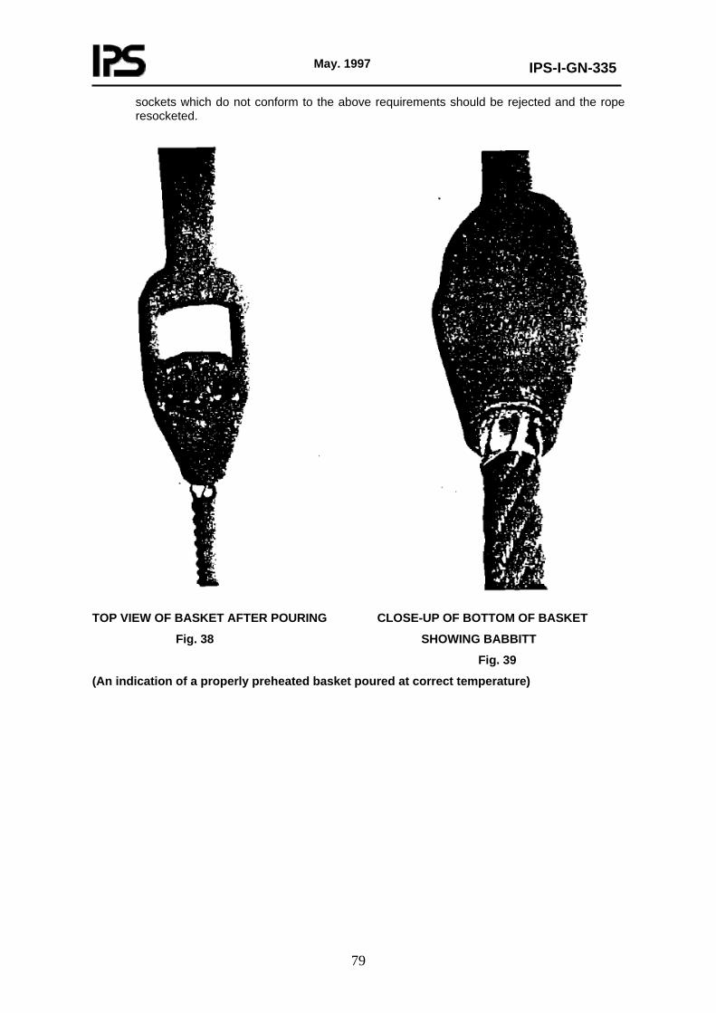
May. 1997
IPS-I-GN-335
79
sockets which do not conform to the above requirements should be rejected and the rope resocketed.
TOP VIEW OF BASKET AFTER POURING CLOSE-UP OF BOTTOM OF BASKET
Fig. 38 SHOWING BABBITT
Fig. 39
(An indication of a properly preheated basket poured at correct temperature)
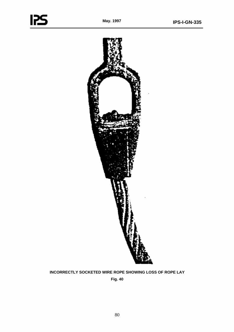
May. 1997
IPS-I-GN-335
80
INCORRECTLY SOCKETED WIRE ROPE SHOWING LOSS OF ROPE LAY
Fig. 40

May. 1997
IPS-I-GN-335
81
APPENDIX D
CHECKLIST FOR INITIAL AND PERIODIC INSPECTION AND
TEST OF ELECTRIC ELEVATORS
Page 1 of 3
ADDRESS OF BUILDING ....................................................................
EQUIPMENT No. ..........................TEST DATE ...................................
RATED CAPACITY ....RATED SPEED ..... CLASSIFICATION ...........
TYPE OF OPERATION ............. DATE OF INSTALLATION ...............
ADDITIONAL INFORMATION .............................................................
ITEM DESCRIPTION CONDITION
INSIDE THE CAR1 Locking function 2 Power-Door operation 3 Car doors and electric contact 4 Emergency doors in blind hoistway 5 Emergency-Release switch in car 6 Capacity and data plate 7 Car enclosure 8 Car illumination 9 Operating and control devices
10 Car floor, sills, and landing sills 11 Protection of projections and recesses in hoistway 12 Car emergency signals 13 Ventilation of passenger elevator 14 Closing speed of power doors
OUTSIDE HOISTWAY15 Hoistway enclosures and doors 16 Hoistway access switches 17 Car platform guard 18 Types of entrance 19 Vision panels 20 Hoistway door locking device 21 Parking devices 22 Access to hoistway 23 Emergency power system 24 Access to pit
TOP OF CAR25 Car and counterweight top clearance 26 Wire rope fastenings and sheaves 27 Traveling cables 28 Normal terminal stopping device 29 Final terminal stopping device
(to be continued)

May. 1997
IPS-I-GN-335
82
APPENDIX D (continued)
Page 2 of 3 ITEM DESCRIPTION CONDITION
30 Speed limiting switches 31 Windows in hoistway 32 Governor rope 33 Hoistway dimensions and clearance 34 Stop switch on car top 35 Top of car operating device 36 Top emergency exit and refuge space 37 Counterweight 38 Counterweight safeties 39 Car top light and outlet 40 Crosshead data plate 41 Multiple hoistway 42 Construction of hoistway 43 Floor over hoistway 44 Venting of hoistway 45 Guide rails and fastenings 46 Raceway and wiring in hoistway 47 Pipes and ducts in hoistway 48 Landing sill guards 49 Suspension rope hitch plate 50 Wire rope data plate crosshead 51 Wire rope data tag. suspension rope 52 Rope sockets
MACHINERY SPACES AND MACHINE ROOM53 Governor tripping speed 54 Governor overspeed switch
55 Governor seal 56 Enclosure of machine room spaces 57 Access to machinery spaces 58 Access doors 89 Head room in machinery spaces 60 Lighting of machine room and machinery
Spaces
61 Ventilation of machinery and control spaces 62 Guards for exposed equipment 63 Visual check of gears and bearing 64 Driving machine 65 Physical ground, electrical equipment 66 Mainline disconnects
(to be continued)

May. 1997
IPS-I-GN-335
83
APPENDIX D (continued)
Page 3 of 3 ITEM DESCRIPTION CONDITION
PIT67 Bottom clearance for car and counterweight
and runby
68 Oil buffer plunger return 69 Oil buffer oil level gage 70 Oil buffer data plate 71 Spring buffer data plate 72 Solid bumpers 73 Buffer switches (type c safeties) 74 Marking plate for safeties 75 Counterweight guard 76 Normal terminal stopping devices 77 Guard between pits 78 Access 79 Illumination 80 Stop switch 81 Compensating sheave switch 82 Floor of pit, level
TESTS 83 Speed load 84 Car and counterweight safeties 85 Governor 86 Governor overspeed switch and car safety
mechanism switch
87 Level of car platform 88 Oil buffer 89 Normal terminal stopping device 90 Final terminal stopping device
91 Brake 92 Operation on emergency power
Note:
Use separate sheet and attach.
PERFORMED BY ............. INSPECTOR ................... DATE ..................

May. 1997
IPS-I-GN-335
84
APPENDIX E
CHECKLIST FOR INITIAL AND PERIODIC INSPECTION AND
TEST OF HYDRAULIC ELEVATORS
Page 1 of 4
ADDRESS OF BUILDING .................................................................
EQUIPMENT No. ........................ DATE ............................................
RATED CAPACITY .... RATED SPEED ...... CLASSIFICATION .......
TYPE OF OPERATION ...... DATE OF INSTALLATION ...................
ADDITIONAL INFORMATION ............................................................
ITEM DESCRIPTION CONDITION
INSIDE THE CAR1 Emergency stop switch 2 Car emergency signals 3 Rated load-platform area 4 Capacity and data plates 5 Signs in freight elevator 6 Car enclosure 7 Ventilation of passenger elevator 8 Ventilation of freight elevator 9 Side emergency exits
10 Car door or gate 11 Car door or gate electric contacts 12 Closed position of car door or gate 13 Power opening of doors or gates 14 Power closing of doors or gates 15 Door closing force 16 Closing speed of power doors 17 Door re-opening device 18 Floating platform 19 Collapsible gate, passenger elevator 20 Collapsible gate, freight elevator 21 Car lighting 22 Car emergency lighting 23 Floor numbers 24 Car platform guard
OUTSIDE HOISTWAY 25 Power closing of hoistway doors
26 Sequence operation 27 Hoistway enclosure 28 Type of entrance
(to be continued)

May. 1997
IPS-I-GN-335
85
APPENDIX E (continued)
Page 2 of 4 ITEM DESCRIPTION CONDITION
29 Vision panels 30 Hoistway door locking device 31 Elevator parking device 32 Access to hoistway 33 Emergency power system 34 Access to pit
TOP OF CAR35 Traveling cable 36 Speed limiting switches 37 Windows in hoistway 38 Governor rope 39 Car and counterweight top clearance 40 Hoistway dimensions and clearance 41 Normal terminal stopping device 42 Final terminal stopping device 43 Stop switch on car top 44 Top of car operating device 45 Top emergency exit and refuge space 46 Counterweight 47 Counterweight safeties 48 Car top light and outlet 49 Crosshead data plate 50 Multiple hoistway 51 Construction of hoistway 52 Floor over hoistway 53 Venting of hoistway
54 Venting of hoistway 55 Raceway and wiring in hoistway 56 Pipes and ducts in hoistway 57 Landing sill guards 58 Wire rope hitch plate 59 Wire rope data plate, crosshead 60 Wire rope data tag 61 Rope sockets 62 Leveling switches
MACHINERY SPACES AND MACHINE ROOM63 Access 64 Machinery space 65 Machine room enclosures
(to be continued)

May. 1997
IPS-I-GN-335
86
APPENDIX E (continued)
Page 3 of 4 ITEM DESCRIPTION CONDITION
MACHINERY SPACES AND MACHINE ROOM (Continued)66 Physical ground, electric equipment 67 Power supply 68 Lighting and ventilation 69 Mainline disconnect 70 Numbering of machines and disconnect switches 71 Pumps 72 Drives 73 Relief and check valves 74 Flexible hose and fittings 75 Tanks and oil level 76 Drip pans 77 Piping and supports 78 Control valves 79 Pressure tanks 80 Guards for exposed equipment 81 Visual check of gears and bearings
PIT82 Access 83 Illumination 84 Stop switch 85 Cylinder air relief 86 Guards between pits 87 Counterweight guard 88 Oil buffer data plate 89 Spring buffer data plate
90 Construction of oil buffers 91 Oil buffer oil level gage 92 Solid bumpers 93 Construction of solid bumpers 94 Construction of spring buffers 95 Clearance and runby 96 Protection of space below pit 97 Cylinder oil collection
(to be continued)

May. 1997
IPS-I-GN-335
87
APPENDIX E (continued)
Page 4 of 4 ITEM DESCRIPTION CONDITION
PIT (Continued)100 Pipes, valves and fittings 101 Piping and supports 102 Normal terminal stopping devices 103 Final terminal stopping devices 104 Car safeties 105 Type of safeties identified 106 Marking plate for safeties 107 Plunger 108 Plunger fastening 109 Cylinder 110 Floor of pit, level
TESTS111 Relief valve 112 Static load 113 Stop ring 114 Operation under fire or other emergency
Conditions
115 Safeties 116 Oil buffer 117 Normal terminal stopping device 118 Final terminal stopping device 119 Operation on emergency power 120 Speed load test
Note:
Use separate sheet and attach.
Performed by Inspector Date


![FnIO G-Series: GN-9481 / GN-9482 / GN-9483Spec] GN-9481_GN...Run-Time System Multiple PLC Tasks Program Languages IEC 61131-3 (LD, IL, ST, FBD, SFC) OPC-Server GN-9481 Not supporting](https://img.pdfslide.us/doc/110x75/5fcf359602c376594f0af992/fnio-g-series-gn-9481-gn-9482-gn-9483-spec-gn-9481gn-run-time-system-multiple.jpg)