Embed Size (px)
Citation preview
IPS-M-GN-340
This Standard is the property of Iranian Ministry of Petroleum. All rights are reserved to the owner. Neither whole nor any part of this document may be disclosed to any third party, reproduced, stored in any retrieval system or transmitted in any form or by any means without the prior written consent of the Iranian Ministry of Petroleum.
MATERIAL STANDARD
FOR
MOBILE CRANES-POWER DRIVEN
ORIGINAL EDITION
JULY 1997

July 1997
IPS-M-GN-340
1
CONTENTS : PAGE No.
1. SCOPE ............................................................................................................................................ 3
2. REFERENCES ................................................................................................................................ 3
3. CONFLICTING REQUIREMENTS.................................................................................................. 5
4. UNITS .............................................................................................................................................. 5
5. DEFINITION OF TERMS ................................................................................................................ 5
6. STRUCTURAL DESIGN ................................................................................................................. 8
6.1 Analysis ................................................................................................................................... 8
6.2 Application of Loads............................................................................................................... 8
6.3 Material Requirements............................................................................................................ 8
6.4 Welding of Critically Stressed Components ...................................................................... 10
6.5 Non-Destructive Examination Components....................................................................... 11
6.6 Stability .................................................................................................................................. 11
7. MECHANICAL EQUIPMENT ........................................................................................................ 13
7.1 Steel Wire Ropes................................................................................................................... 13
7.2 Drums and Rope Reeving Components ............................................................................. 14
7.3 Lifting Hooks ......................................................................................................................... 15
7.4 Shackles................................................................................................................................. 15
7.5 Overhauling Weight .............................................................................................................. 15
7.6 Rope Pulleys.......................................................................................................................... 15
7.7 Gearing................................................................................................................................... 16
7.8 Clutches ................................................................................................................................. 16
7.9 Brakes for Crane Motions .................................................................................................... 16
7.10 Lubrication........................................................................................................................... 18
7.11 Slewing................................................................................................................................. 18
7.12 Guarding .............................................................................................................................. 18
7.13 Controls ............................................................................................................................... 19
7.14 Manual Operation................................................................................................................ 19
7.15 Crane Driver’s Station ........................................................................................................ 19
7.16 Internal Combustion Engines ............................................................................................ 20
8. ELECTRICAL EQUIPMENT ......................................................................................................... 20
8.1 Electric Motors ...................................................................................................................... 20
8.2 Control Gear .......................................................................................................................... 21
8.3 Protective Gear...................................................................................................................... 21
8.4 Fixed Cables, Wiring and Other Conductors ..................................................................... 22
9. HYDRAULIC EQUIPMENT ........................................................................................................... 23
9.1 General Requirements.......................................................................................................... 23
9.2 Power Transmission ............................................................................................................. 24
July 1997
IPS-M-GN-340
2
10. PNEUMATIC EQUIPMENT......................................................................................................... 24
10.1 General Requirements........................................................................................................ 24
10.2 Application........................................................................................................................... 25
11. SAFETY ...................................................................................................................................... 25
12. INSPECTION AND TESTING ..................................................................................................... 28
12.1 Inspection ............................................................................................................................ 28
12.2 Testing ................................................................................................................................. 28
13. PROTECTION OF CRANE STRUCTURE.................................................................................. 34
14. GUARANTEE AND WARRANTY............................................................................................... 34
APPENDICES :
APPENDIX A INFORMATION RECOMMENDED SUPPLIED WITH ENQUIRY OR ORDER BY PURCHASER............................................................. 44
APPENDIX B INFORMATION TO BE SUPPLIED BY MANUFACTURER ................................. 47
APPENDIX C MOBILE CRANE DATA SHEETS ......................................................................... 49
July 1997
IPS-M-GN-340
3
1. SCOPE
1.1 This IPS Standard specifies the requirements for the design, construction and testing of power-driven mobile and semi-mobile cranes either road wheel mounted, crawled mounted, or truck mounted, including any combination of the following characteristics, for use in Iranian Petroleum Industries.
a) Fully mobile.
b) Semi-mobile.
c) Fully slewing.
d) Part-slewing.
e) Non-slewing.
The standard covers articulated jib cranes mounted on load carrying vehicles and generally referred to as lorry loaders.
Typical mobile crane types and jib configuration including typical lorry loader features are shown in Figs. 2 to 6.
1.2 No deviations or exceptions from this Standard shall be permitted without the written approval of the Company.
The intended deviations shall be listed separately by the Vendor and supported by reasons thereof for purchaser’s consideration.
1.3 Compliance be the crane Manufacturer with the provisions of this Standard does not relieve him of the responsibility of furnishing the cranes and accessories of proper design, to meet all requirements at specified service conditions.
1.4 All the necessary information regarding the conditions under which the crane is to be used, together with the information indicated in Appendix A, shall be supplied by the Purchaser with enquiry or order.
1.5 The Manufacturer shall supply with the tender the appropriate information indicated in Appendix B regarding the construction of the crane.
2. REFERENCES
Throughout this Standard the following dated and undated standards/codes are referred to. These referenced documents shall, to the extent specified herein, form a part of this standard. For dated references, the edition cited applies. The applicability of changes in dated references that occur after the cited date shall be mutually agreed upon by the company and the vendor. For undated references, the latest edition of the referenced documents (including any supplements and amendments) applies.
AGMA (AMERICAN GEAR MANUFACTURERS ASSOCIATION)
210.02 "Surface Durability of Spur Gear Teeth"
211.02 "Surface Durability of Hevical and Herring Bone Gear"
220.02 "Rating the Strength of Spur Gear Teeth"
AISC (AMERICAN INSTITUTE FOR STEEL CONSTRUCTION)
"Specification for the Design Fabrication and Erection of Structural Steel for Buildings"
July 1997
IPS-M-GN-340
4
AISI (AMERICAN IRON AND STEEL INSTITUTE)
API (AMERICAN PETROLEUM INSTITUTE)
SPEC 9A "Specification for Wire Ropes"
ASME (AMERICAN SOCIETY OF MECHANICAL ENGINEERS)
Boiler and Pressure Vessel Code, Sec. IX "Welding and Brazing Qualification"
ASTM (AMERICAN SOCIETY FOR TESTING AND MATERIALS)
A 320 "Specification for Alloys-Steel Bolting Materials for Low Temperature Service"
A 578 "Specification for Straight-Beam Ultrasonic Examination of Plain and Clad Steel Plates for
Special Applications"
A 770 "Specification for Through-Thickness Tension Testing Steel Plates for Special Applications"
E 186 "Referenced Radiographs for Heavy-Walled (51 to 114 mm) Steel Casting"
E 280 "Referenced Radiographs for Heavy-Walled (114 to 305 mm) Steel Castings"
E 446 "Referenced Radiographs for Steel Castings up to 51 mm in Thickness"
AWS (AMERICAN WELDING SOCIETY)
D 1.1 "Structural Welding Code"
D 14.3 "Specification for Welding Earthmoving and Construction Equipment"
BSI (BRITISH STANDARDS INSTITUTE)
2573: Part 1 "Specification for Classification, Stress Calculations and Design Criteria for Structures"
IPS (IRANIAN PETROLEUM STANDARDS)
IPS-M-EL-271 “Low Voltage Cables and Wires”
IPS-M-EL-272 “Medium and High Voltage Power Cables”
IPS-M-EL-290 “General Electric Items”
IPS-M-EL-132 "Induction Motors"
IPS-M-EL-138 "Generators"
IPS-M-EL-270 "Cables"
IPS-M-GN-160 "Lifting Hooks, Shackles and Eye Bolts"
IPS-M-PM-290 "Internal Combustion Reciprocating Engines"

July 1997
IPS-M-GN-340
5
SAE (SOCIETY OF AUTOMOTIVE ENGINEERS)
J 429 "Fasteners, Mechanical and Material Requirements for Externally Threaded"
3. CONFLICTING REQUIREMENTS In case of conflict between documents relating to the inquiry or order the following priority of documents shall apply:
First priority : Purchase order and variations there to Second priority : Data sheets Third priority : This Standard specification
All conflicting requirements shall be referred to purchaser in writing. The Purchaser will issue confirmation document if needed for clarification. 4. UNITS This Standard is based on International System of Units (SI), except where otherwise specified. 5. DEFINITION OF TERMS For the purposes of this IPS Standard, the following definitions apply. 5.1 Anchorage Means of securing the base of an articulated jib crane to a vehicle chassis, or a steel wire rope to a drum or to the crane structure. 5.2 Articulation The ability to pivot about a pin joint. 5.3 Articulated Jib A jib having two or more members capable of articulation. 5.4 Blocking-Up Base (Blocked Condition) The effective dimensions of the supporting base when outriggers or other supporting means are sed. 5.5 Coefficient of Utilization The ratio of the minimum breaking load of the rope to its working load limit. 5.6 Derricking or Luffing Angular movement of the crane jib in a vertical plane. Note: Cranes which lift their loads by derricking the jib while the load is suspended from a fixed hook on the jib should be described as lifting their loads by derricking only. 5.7 High of Lift The vertical distance between the floor level or datum level, and the lowest point of the throat of the
July 1997
IPS-M-GN-340
6
hook when the hook is in the highest working position. 5.8 Hoisting The motion of lifting or lowering of the load in a vertical direction. 5.9 Jib Angle Jib angle is the angle subtended between the horizontal plan and a jib axis as defined by the Manufacturer. 5.10 Jib Length The shortest distance between the centers of the fulcrum of the jib and jib head pulley pin. 5.11 Minimum Breaking Load The minimum breaking load value given in the appropriate standard or specification below which a sample of the rope will not fail when tested in the prescribed manner. 5.12 Fully Mobile Cranes capable of traveling under their own power with loads up to the maximum for which they are designed, suspended at any point within the working range. 5.13 Semi-Mobile Cranes which are not designed to travel with loads suspended. 5.14 Lorry Loader A combination of a load carrying vehicle (or lorry) and an articulated jib crane that is used for the handling of goods on or off the vehicle. 5.15 Outreach The horizontal distance from the centreline of the lifting hook to the nearest point of the machine other than the jib. (This dimension varies in accordance with the operating conditions of the machine.) 5.16 Outrigger Beam A supporting device that can be extended at the side of a mobile crane and is normally capable of being used to jack the crane into a level attitude. 5.17 Overload Prevention Device A device that prevents the operator moving load into an overload condition. 5.18 Radius The horizontal distance measured at ground level between the centreline of the hook and perpendicular projected through the center of rotation. Note: In the case of a non-slewing crane, the horizontal distance from the centreline of a lifting hook to the centreline of the nearest axle, bogie or track, measured at ground level, can be assumed to be the radius for the purpose of this definition. 5.19 Safe Working Load (SWL) The maximum load which can be safely handled by a crane at a specified position and under specified conditions. The safe working load includes the weight of the hook or load handling device
July 1997
IPS-M-GN-340
7
unless otherwise specified. 5.20 Slewing Rotary motion of a crane jib and superstructure about a vertical axis. 5.21 Fully-Slewing The ability to slew continuously in either direction with a load, up to the maximum for which the crane is designed, suspended. 5.22 Part-Slewing The ability to slew but unable to comply with the definition of 5.21. 5.23 Stabilizer A load supporting leg usually extended outwards from the side of a crane or lorry loader to provided more stable base. The leg can be extended to reach the ground either manually or hydraulically. It requires to be retracted, stowed and secured for transit. 5.24 Tail Radius The maximum distance between the center of rotation and any part of the revolving superstructure other than the jib. 5.25 Telescoping The extension or retraction of the jib along its longitudinal axis by movement of the sections contained within the jib. 5.26 Tipping A crane is deemed to be in a condition of tipping when it is subjected to an overturning moment which cannot be increased, even by a small amount, without causing the crane to overturn. 5.27 Stable A crane is said to be stable when the sum of the stabilizing moments is greater than the sum of the overturning moments. 5.28 Working Load Limit The maximum load which an item of equipment is designed to raise, lower or suspend. 5.29 Dead Loads All the loads of constant magnitude and position that act permanently on the structure or member. 5.30 Live Loads Any load except wind load that gives rise to variation of stress in a member. Such variation may be due to any change of position or magnitude of an externally applied load or to the movement of the crane structure itself. 5.31 Inertia Forces The forces produced by change of velocity. 5.32 Wind Load The forces produced by the velocity of the wind, which is assumed to act horizontally.
July 1997
IPS-M-GN-340
8
5.33 Permissible Working Stress The stress numerically equal to the basic stress multiplied by the relevant duty factor and the factor corresponding to the load combination. 5.34 Permissible Fatigue Stresses Stresses as set out in Section 6.2.2. 5.35 Service Conditions The crane is deemed to be under service conditions when it is operating without load or with a load up to the maximum safe working load. 5.36 Critical Component Any component of the crane assembly devoid of redundancy and/or auxiliary restraining devices whose failure would result in an uncontrolled descent of the load or uncontrolled rotation of the upper structure. 6. STRUCTURAL DESIGN 6.1 Analysis All critical structural components shall be designed to conform with the allowable unit stresses specified in the latest edition of the AISC Specification for the Design, Fabrication and Erection of Structural Steel for Buildings, when subjected to dead load, plus the design and horizontal loads defined in Paragraphs 6.2. For structural steels other than those listed in the AISC specification, Compatibility with the AISC allowable unit stresses should be established and documented through discussions with the AISC technical staff. Connecting joints (welded, pinned or bolted) shall develop either the load carried by the connected members or the strength of the connected members based on AISC allowables, but in no case less than 50% of the tensile strength of the controlling member. Allowable shear stresses and width-to-thickness ratios shall be in accordance with the applicable provisions of AISC. 6.2 Application of Loads The structure as a whole and each part of it shall be designed to withstand the load combinations given in latest edition of BSI Standard 2573: Part 1, Section 3, including all aspects such as horizontal loads, loads due to climatic conditions and natural phenomena, impact factor, and etc. 6.3 Material Requirements 6.3.1 Materials Materials to be employed in the Manufacture and fabrication of critical components of the crane shall comply with the Manufacturer’s design requirement for strength and fracture toughness:
1) Metals The design requirement shall define the following properties of metallic materials:
Chemical Composition Limits Heat Treatment Condition Mechanical property Limits a) Yield Strength b) Tensile Strength c) Elongation d) Fracture Toughness
2) Testing
July 1997
IPS-M-GN-340
9
The design requirement specification shall detail the methods of testing to verify the specified properties are present in the component in the as manufactured or as fabricated condition. To the maximum extent possible, all materials shall be purchased to specifications of recognized Standardization Organization. 3) Wire Rope Rope shall be of construction specified by the crane manufacturer for that service. The requirements of the latest edition of API spec. 9A, "API Specification for Wire Rope" shall be the minimum specification for wire ropes to be employed. Rotation resistant ropes and fiber core ropes shall not be used for boom hoist reeving. The design factor for wire rope shall be the total nominal strength of all parts of wire rope in the system divided by the load imposed while supporting the following loads:
a) For load hoist ropes, the load to be lifted. b) For other ropes, the dead load plus the load to be lifted.
6.3.2 Tracebility Tracebility of materials for critical components and parts shall be achieved through a systematic program of serialization and identification indexed to process, inspection, and test records of controlled manufacturing procedures. The Manufacturing procedures shall be in sufficient written detail to permit duplication of the original processing at any time specified. Documentation of material origins shall be that of the basic producer in lieu of certifications prepared by third party material suppliers. In the absence of supporting documentation, materials shall not be employed in fabrication until the Manufacturer conducts or has conducted tests and examinations to verify compliance with design requirements. Critical structural components shall not be produced from materials which lack supporting documentation to verify the properties are as specified in the design and manufacturing specifications. 6.3.3 Fracture toughness All critical components of the crane shall exhibit Charpy impact energy values assuring the transition from brittle to ductile fractures at least indexed at the lowest anticipated service temperature. Other appropriate fracture control plans considering toughness, allowable flaw size, and inspection requirements may be employed if desired. If a fitness for purpose criteria is employed, that details of the analysis shall be documented for examination, upon request, by the Purchaser. The design service temperature shall be indicated on the nameplate. 6.3.4 Castings
1) Prototype Castings The validity of the casting procedure for all critical component castings shall be verified by conducting examinations and tests on the first lot cast and/or each change in pattern design or pouring practice. Destructive testing and/or radiographic examinations supplemented by other nondestructive examinations are considered appropriate for this purpose. If radiography is employed, the sources of radiation for examination of casting section less than two inches (50.8 mm) in thickness shall be from an X-ray generator or from Iridium 192 isotopes. The prototype evaluation shall demonstrate the ability of the casting procedure to consistently produce critical component casting soundness not less than the radiography standards of Table 3. 2) Production Castings The method of nondestructive examination and the acceptance criteria for examination of the critical component production castings shall be established by the Manufacturer from consideration of material properties, environmental exposure, and stress level(s) in critical areas of the casting. The extent of the examination shall be adequate to assure castings
July 1997
IPS-M-GN-340
10
possess soundness adequate for the intended purpose; i.e. examine all critically stressed areas. 3) Thermal Treatment All castings for critical components shall be subjected to a normalize and temper, quench and temper, or stress relief heat treatment after shake out and cooling to ambient temperature. The tempering and stress relief temperatures employed shall be appropriate to the alloy content and strength level required of the component, but shall not be less than 593°C (1100°F).
6.3.5 Bolting Threaded fasteners subject to static and/or dynamic tensile loading (other than preload) employed in joining of critical components of the crane shall meet the requirement of ASTM A320. The specific grade of material shall be selected to meet strength requirements, fracture toughness, and corrosion resistance of the service environment. Where bolting of higher strengths than permitted by ASTM A320 is desired to be employed, the materials shall meet the specifications outlined in SAE Recommended Practice J429G. Qualification of the higher strength materials shall be by testing of two threaded fasteners from each heat of steel for proof of mechanical strength, hardness. and Charpy impact energy values. The minimum average impact energy obtained from a set of three test shall be 40.6 Joules at minus 17.8°C with no single test value less than 29.8 Joules. 6.3.6 Plate Critical structural elements fabricated from plate which must transfer loads through the thickness or the short transfers dimension of the plate shall be ultrasonically inspected in accordance with ASTM A578, Level II quality, and shall be tested for resistance to lamellar tearing in accordance with the procedures and requirements of ASTM A770.
TABLE 1 - ACCEPTANCE CRITERIA BASED ON ASTM RADIOGRAPHIC STANDARDS
(MAXIMUM ACCEPTABLE SEVERITY) TAPE OF
DISCONTINUITY ASTM E 446 ASTM E 186 ASTM E 280
CategoryA(gasporosity) CategoryB(sandandslag) Category C (shrinkage)
Serverity level 3 Serverity level 2 Type CA, level 2 Type CB, level 2 Type CC, level 1 Type CD, level I
Severity level 2 Serverity level 2 Type 1, level 1 Type 2, level 2 Type 3, level 1
Serverity level 2 Serverity level 2 Type 1, level 1 Type 2, level 1 Type 3, level 1
All discontinuities D, E, F and G are unacceptable. 6.4 Welding of Critically Stressed Components 6.4.1 General All welding procedures for joining of structural load bearing or load transfer members of the crane and the performance of welders employing these procedures shall be qualified in accordance with a recognized standard such as the American Welding Society Specification for Welding Earthmoving and Construction Equipment, AWS D14.3, the American Welding Society Structural Welding Code. AWS D1.1, or the American Society of Mechanical engineers Boiler and pressure vessel Code, Section IX, Welding and Brazing Qualification. 6.4.2 Welding procedures A written procedure specification shall be prepared for all welding. Prequalified procedures as defined in AWS D1.1 and AWS D14.3 are acceptable only for joining the materials using the
July 1997
IPS-M-GN-340
11
consumbles, joint configurations, and procedure limits specified therein. The welding of materials or use of procedures other than those defined by the AWS specification shall be qualified by testing a sample weld produced in accordance with a written procedure and tested in accordance with one of the standard listed in paragraph 6.4.1. 6.4.3 Welder performance The performance of welders shall be verified by actual destructive testing or alternatively by radiographic examination. Radiographic examination shall be limited to groove welds using the shielded metal arc, submerged arc, gas tungsten arc, gas metal arc (globular arc, spray arc or pulsating arc only) and flux cored arc processes. The performance of welder employing short-circuiting (short arc) gas metal arc welding processing shall be qualified by destructive testing only. 6.4.4 Welding properties The strength and fracture toughness of welds and heat affected zones in critical components shall meet the minimum design specification requirements of the materials being joined. Mechanical testing shall be conducted during procedure qualification to verify the required proportions of the weld and heat affected zones are attained by the controls outlined in the welding procedure specification. 6.5 Non-Destructive Examination Components 6.5.1 Non-destructive examination procedures The manufacturer shall establish written nondestructive examination procedures for the examination of critical structural components of the crane. The procedures shall consider the stage of manufacture in which the examination is to be performed, the accessibility to examination methods, and the configuration of the component to be examined. These procedures shall be employed by the manufacture’s personnel and/or any contract nondestructive examination personnel utilized by the manufacturer. The acceptance criteria on radiographic examination shall be as indicated in Table 1. 6.5.2 Minimum extent of non-destructive examination The Manufacturer shall identify all critical components of the crane. These components shall be subjected to nondestructive examinations in accordance with a recognized workmanship standard or at the option of the Manufacturer by a written examination procedure and acceptance criteria developed in a fitness for purpose fracture control plan. The extent of nondestructive examination of noncritical components is also the responsibility of the Manufacturer. 6.6 Stability 6.6.1 Verification of stability 6.6.1.1 General Calculations shall be made to verify that the crane is stable under the conditions specified in 6.6.1.2 and 6.6.1.3. 6.6.1.2 Operating in service conditions (with wind)
1) applied load = 1.1p 2) wind load = W1
3) inertia forces = D Where: P is the safe working load for the crane as defined in 5.19 at the appropriate radius; W1 is the wind loading applied by in-service winds at speeds specified by the
July 1997
IPS-M-GN-340
12
Purchaser. D are the inertia forces. For machines on which operating accelerations cannot be
varied. The resulting inertia forces shall be taken into account. 6.6.1.3 Static stability (hook loading simulating dynamic condition)
1) Articulated jib cranes ( e.g. excavators used as cranes and lorry loaders); applied load = 1.4 p 2) Cargo handling cranes; on outriggers or crawler tracks, applied load = 1.33 p for free on wheels, applied load = 1.5 p 3) Other cranes including fully mobile; applied load =1.25p+ 0.1 F
Where:
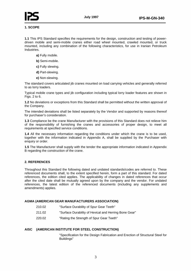
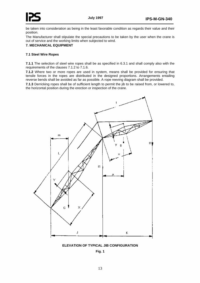
F is the load from jib weight G and fly jib weight g referred to the head of the jib F1 or that of the fly jib F2 (see Fig. 1).
This calculation does not include any allowance for the effect of wind during testing. The Manufacturer shall make allowance for this so that the crane is capable of being tested in wind speeds of up to 8.3 m/s. 6.6.1.4 Static without load (backward stability) 6.6.1.4.1 General Counter weighting shall be limited by the weight distribution given in 6.6.1.4.2 and 6.6.1.4.3, the appliance being in the following conditions:
1) placed on a firm level supporting surface; 2) equipped with shortest specified jib set at the minimum radius specified by the Manufacturer; 3) with hook, hook block or other load handling equipment setting on the ground; 4) equipped with the longest specified jib or jib and fly jib combination set at the maximum angle and with in service wind acting from the least favorable position.
The specified weight distribution criteria shall be satisfied for each counterweight condition with the crane rotated to the last stable positions permitted by the Manufacturer. 6.6.1.4.2 Crawler cranes The horizontal distance between the center of gravity of the crane and the axis of rotation shall not exceed 70% of the radial distance from the axis of rotation to the backward tipping line in the least stable direction. 6.6.1.4.3 Truck and wheel mounted cranes With the longitudinal axis of the rotating superstructure of the crane at 90° to the longitudinal axis of the carrier, the total load on all wheels or stabilizers on the side of the carrier under the boom shall be not less than 15% of the total weight of the crane. With the longitudinal axis of the rotating superstructure of the crane in line with the longitudinal axis of the carrier in either direction, the total load on all wheels or stabilizers under the lighter loaded end of the carrier shall be not less than 15% of the total weight of the crane. 6.6.1.5 Static without load in out of service condition The effect of the overturning moment due to out-of service wind shall be calculated from the appropriate wind loading specified. 6.6.2 Additional requirements The stability calculations shall be made with the crane in the least favorable position; moreover, all the loads, dead loads, counter weights accessories, etc. that have an influence on the stability shall
July 1997
IPS-M-GN-340
13
be taken into consideration as being in the least favorable condition as regards their value and their position. The Manufacturer shall stipulate the special precautions to be taken by the user when the crane is out of service and the working limits when subjected to wind. 7. MECHANICAL EQUIPMENT 7.1 Steel Wire Ropes 7.1.1 The selection of steel wire ropes shall be as specified in 6.3.1 and shall comply also with the requirements of the clauses 7.1.2 to 7.1.6. 7.1.2 Where two or more ropes are used in system, means shall be provided for ensuring that tensile forces in the ropes are distributed in the designed proportions. Arrangements entailing reverse bends shall be avoided as far as possible. A rope reeving diagram shall be provided. 7.1.3 Derricking ropes shall be of sufficient length to permit the jib to be raised from, or lowered to, the horizontal position during the erection or inspection of the crane.
ELEVATION OF TYPICAL JIB CONFIGURATION
Fig. 1
July 1997
IPS-M-GN-340
14
7.1.4 Where ropes are used to support a fixed offset fly jib, the distances between the support point centers shall be specified by the Manufacturer to enable the fly jib offset to be correctly set under working conditions.
7.1.5 The rope termination (i.e. the terminal fitting together with the means of its attachment to the rope) shall be capable of withstanding not less than 80% of the minimum breaking load of the rope.
7.1.6 Rope anchorages shall be protected by not less than two dead turns remaining on the drum when the rope is paid out to its maximum working length. Rope anchorages shall be secure and readily accessible. If two or more ropes lead off a drum, provision shall be made for adjustment of the rope length at the anchorage end.
7.2 Drums and Rope Reeving Components
7.2.1 General
7.2.1.1 Drum shall be either plain or grooved.
7.2.1.2 Means shall be provided to prevent the rope in advertently leaving the drum. The drum flanges shall project a distance of not less than two rope diameters beyond the outer layer of rope in all circumstances.
Note:
A spur or other wheel secured to the drum can form one of the flanges provided it is adequately guarded.
7.2.1.3 The inclination of the rope at the point of a lead off from he drum shall not exceed in 1 in 12 each side of a centreline which represent the true lead-off.
7.2.1.4 If a rope leads off against the helix angle of the drum grooving, care shall be taken to prevent the rope rubbing against an adjacent turn. In extreme cases the clearance between turns can be increased in order to meet this requirement.
7.2.2 Drum diameters
The minimum winding diameter of a plain drum or of a grooved drum measured at the rope centers shall not be less than 15 times the rope diameter, irrespective of the rope construction.
7.2.3 Drum groove
7.2.3.1 Grooving shall be smooth and free from surface defects liable to damage the rope. The edges shall be rounded.
7.2.3.2 The contour at the bottom of the groove shall be circular over a minimum angle of 120°.
7.2.3.3 The radius of the groove shall exceed the radius of the ropes by not less than the value given in Table 2.
7.2.3.4 The grooves shall be so pitched that the clearance between adjacent turns of rope is not less than the dimension given in Table 3.
7.2.3.5 If compensating links are used on the free or returned ends of two parts of rope to equalize the load, the drum grooves shall be of identical diameters to ensure that the two parts of the rope wind equally, and the difference in the length of the ends of the rope is maintained within the capacity of the compensating links throughout the full range of lift.
July 1997
IPS-M-GN-340
15
TABLE 2 - MINIMUM GROOVE RADII FOR ROPE DRUMS AND PULLEYS Nominal diameter of rope (d) Minimum amount by which groove
radius shall exceed rope radius mm mm
Up to and including 16 Over 16 up to and including 26 Over 26 up to and including 28 Over 28
0.8 1.2 1.6 2.4
TABLE 3 - MINIMUM ROPE CLEARANCE FOR DRUM GROOVES Nominal diameter of rope (d) Minimum clearance between turns
Mm Mm Up to and including 13 Over 13 up to and including 28 Over 28
1.6 2.4 3.2
7.3 Lifting Hooks
7.3.1 Lifting hooks shall comply with the requirement of IPS-M-GN-160. Part 1. Hooks shall be provided with an efficient device to prevent the displacement of the sling or the load from the hook.
7.3.2 Swiveling hooks shall be mounted on antifriction bearings suitable for the purpose. If required, a locking device shall be fitted to prevent rotation of the hook.
7.4 Shackles
Shackles shall comply as regards strength and safety with the requirements of IPS-M-GN-160. Part 3. Shackles used for attaching the hook shall be provided with screwed pins. Slotted heads in countersunk screwed pins are not recommended.
7.5 Overhauling Weight
If an overhauling weight used on the rope, it shall have a smooth hole and be bell mounted at the top and bottom to accommodate and provision shall be made to the rope and rope termination. Provision shall be made for the examination of the part of the rope passing through the weight. The overhauling weight shall be designed so as to avoid catching on obstructions.
7.6 Rope Pulleys
7.6.1 Pulley Diameters
The diameter of rope pulleys at the rope centers shall be not less than 18 times the rope diameter. Compensating pulley diameters shall be not less than 15 times the rope diameter.
7.6.2 Pulley grooves
Rope pulleys shall be grooved to a depth not less than 1.5 times the diameter of the rope. The grooves shall be finished smoothly and shall be free from surface defects liable to damage the rope. The edges shall be rounded. The contour at the bottom of the groove shall be circular over an angle of not less than 120. The radius of the groove shall comply with the requirements of 7.2.3.3. The included angle of flare of the sides of the pully groove shall be a maximum of 60 for an angle of lead of 1 in 12.
July 1997
IPS-M-GN-340
16
Note:
The angle of flare may be reduced for smaller angles of lead provided that the flange does not interfere with the rope.
7.6.3 Angle of lead (or fleet Angle)
The angle of lead between the rope and a plane perpendicular to the axis of the pulley shall not exceed 1 in 12.
7.6.4 Guarding
Provision shall be made to retain the rope in the groove.
7.6.5 Supports
Suitably designed supports shall be fitted, where necessary, on the jib and other parts of the structure to prevent chafing of the ropes.
7.7 Gearing
Spur gears shall comply with the latest Editions of AGMA Standards 220.02 and 210.02, and helical and herringbone gears with AGMA 211.02.
7.8 Clutches
7.8.1 General
Clutches shall be designed to transmit the maximum torque for the motion for all conditions of usage.
7.8.2 Sprag clutches
When sprag type clutches are used in hoist and derricking systems, they shall incorporate a positive mechanical lock against failure or be designed to transmit twice the maximum torque imposed by the maximum line pull.
7.9 Brakes for Crane Motions
7.9.1 General
7.9.1.1 Springs for applying brakes shall be of the compression type and shall not be stressed in excess of 80% of the torsional elastic limit of the material.
7.9.1.2 Brakes applied by hand shall not require a force greater than 108 N (25 lbf) at the handle . If applied by foot they shall not require a force greater than 314 N (70 lbf) on the pedal to exert the restraining torque specified in 7.9.2. All control levers and pedals shall be designed and positioned to take account of the requirements of clause 7.13.
7.9.1.3 The wearing surfaces of all brake drums or plates shall be machined and shall be smooth and homogenous.
7.9.1.4 Brake weights, if fitted, shall be positioned and fixed securely to their levers.
July 1997
IPS-M-GN-340
17
7.9.1.5 Brake linings shall be adequately and permanently secure during their effective life.
7.9.1.6 Brake blocks and linings shall be protected from rain, oil, grease or other environmental conditions.
7.9.1.7 Brakes shall be provided with a simple and easily accessible device to compensate for the wear of the linings. This device shall be self compensating whenever practicable.
7.9.1.8 Brakes for securing a hoist or derricking motion shall be held in the applied position by a positive actuating device. Brake mechanisms that rely upon air or fluid under pressure or an electrical mechanism for application shall be supported by an additional positive mechanism.
7.9.1.9 For electro-mechanical brakes, energization of the brake magnet due to back e.m.f of the motor shall be prevented by the control gear in the "off" position isolating the brake magnet, after tripping of the overtravel limit or other appropriate protective device.
7.9.1.10 If electric braking is adopted, the conductors and contact surface of the motor and the control gear shall be proportioned so that the additional duty will not cause overheating.
7.9.2 Individual brake motions
7.9.2.1 General
Means shall be provided for arresting each motion of the crane, and if controlled by a brake, the following minimum requirements shall apply.
7.9.2.2 Hoisting motion brakes
Hoisting motion brakes shall be designed to exert a restraining torque at least 25% greater than maximum torque transmitted to the brake drum from the suspended load under service conditions. In estimating this torque, the effects of friction in the transmission system between the load and the brake shall be ignored.
If free lowering is possible, the temperature of the friction surfaces of the brake shall not exceed the maximum working temperature specified by the manufacturer of the brake linings, after the maximum safe working load has been raised and lowered on the brake five times without pause through the specified height of lift.
7.9.2.3 Derrick motion brakes
For cranes with a derricking motion operated by rope and drum system, the brake shall be designed to exert a restraining torque at least 25% greater than the maximum torque transmitted to the brake drum from the suspended load under service or erection conditions, whichever is the greater. In estimating this torque, the effects of friction on the transmission system between the load and the brake shall be ignored. The main derricking motion brake shall be automatically applied when the derricking control lever is moved to the ’off’ or ’neutral’ position.
7.9.2.4 Cranes with derricking jibs
On cranes having a derricking jib operated through a clutch with the exception of those noted below in (a) and (b), an effective inter locking arrangement shall be provided between the derricking clutch and the pawl sustaining the derricking drum. The interlocking arrangement shall ensure that the clutch cannot be disengaged unless the pawl is in effective engagement with the derricking drum, and the pawl cannot be disengaged unless the clutch is in effective engagement with the derricking drum.
Note:
This need not apply to any crane in which :
July 1997
IPS-M-GN-340
18
a) the hosting drum and derricking drum are independently driven;
b) the mechanism driving the drum is self -locking.
7.9.2.5 Slewing motion brakes
7.9.2.5.1 Slewing brakes
Except when the slewing motion is controlled by reversing clutches, an effective slewing brake shall be provided, designed to exert an adequate restraining torque which will not subject the jib to a declaration greater than that for which it is designed.
7.9.2.5.2 Slewing holding brakes
If restraint is applied by a slewing clutch, a holding brake, capable of preventing movement of the uperstructure under service conditions, shall be fitted.
7.9.2.5.3 Slewing lock
A positive lock or sprag shall be provided to retain the superstructure in a fixed position.
7.9.2.6 Traveling brakes
Effective traveling and parking brakes shall be fitted, capable of securing the unloaded crane on a slope of not less than that on which the machine is designed to travel and in no case shall this be less than 10%. This shall be achieved without the use of chocks. Where the vehicle is subject to road traffic regulations, the conditions specified for brakes in those regulations shall apply.
7.10 Lubrication
All bearings shall be adequately lubricated. Plain bearings or their shifts shall have oil or grease grooves. All lubrication nipples should be of similar size and type and shall be readily accessible.
Where access for lubrication is difficult, bearings shall be such that lubrication is required as infrequently as possible or facilities for lubrication from a remote position shall be provided. A lubrication diagram shall be provided.
7.11 Slewing
For cranes on which the slewing motion is power operated, the slewing mechanism shall be so designed that it is not damaged due to fierce acceleration, braking or reversal of motion. The mechanism shall be designed to withstand the forces specified in section 6. In the case of proprietary slewing rings, it is particularly important that the Manufacturer is consulted and given full details of the loads and duty involved. Attention shall be given to the method of mounting and the bolting requirements for which the manufacturer’s recommendations shall be taken into account.
7.12 Guarding
7.12.1 All gear wheels, pinions and chain drives shall be completely encased unless such parts are so situated in relation to the structure of the crane as to be as safe as if complete encasement were provided.
7.12.2 Effective guards shall be provided for revolving shafts and couplings unless every set screw, bolt or key on any revolving shaft is sunk, shrouded, or otherwise effectively guarded.
July 1997
IPS-M-GN-340
19
7.12.3 All other dangerous parts of the machine shall be guarded adequately.
7.13 Controls
7.13.1 Control positions and markings
Operating levers or wheels shall have clear markings, on or adjacent to them, to indicate their function and mode of operation. If the design of a crane is such that the effect of the steering wheel or any other motion is reversed when the jib is slewed through 180°, an appropriate notice or other indication clearly drawing attention to this shall be provided.
Notes:
1) Where motions can be reversed it is recommended that self-correcting controls are incorporated.
2) All practical measures should be taken to prevent accidental movement of controls.
3) All controls should be placed in a position in accordance with best ergonomic practice with control levers and pedals placed in such positions as to allow the driver/operator, when in his normal position, ample room for operation, as far as possible an unrestricted view of the load and as clear a view as possible of the immediate surroundings, both forward and to each side of that position.
7.13.2 Motion controls
Control arrangements can be specifically designed for ’joy-stick’ control of two movements simultaneously, otherwise they shall be so designed that selection of one movement cannot cause any other movement unless it is for the operation of a safety device or interlock. Control valve systems shall be designed to return to the neutral position when released, except when operational characteristics dictate otherwise.
7.14 Manual Operation
Arrangements for any operation relying wholly on manual effort (i.e. without power assistance) shall be such that an operator turning a handle, a wheel, or pulling a lever shall not be required to exert a mean force in excess of 108 N (25 lbs) continuously or 177 N (40 lbf) as a maximum at a mean speed of 46 m/min (150 ft/min).
7.15 Crane Driver’s Station
Except for lorry loaders or unless stated to the contrary by the Purchaser, a cabins shall be supplied by the Manufacturer. The cabin shall:
a) afford the driver protection from the weather;
b) be fitted with safety glass
c) have a lock fitted to the door to prevent unauthorized entry when the crane is left unattached;
d) have a securely fixed adjustable seat for the driver;
e) be provided with a heater to satisfy statutory requirements;
f) be provided with a means of ventilation;
g) have either natural or artificial illumination to ensure that all charts and instruments are visible to the driver;
h) have safe access to the driver’s cabin.

July 1997
IPS-M-GN-340
20
Note:
The driver should as far as practicable be provided with a clear and unrestricted view of the load and the jib in all normal working positions and as clear a view as possible of the extremity of any forward projection and of the road ahead when the crane is traveling.
7.16 Internal Combustion Engines
7.16.1 Internal combustion engines shall comply with the requirements of IPS-M-PM-290 and a silencer shall be fitted to the exhaust. The exhaust shall not discharge in such a manner as to cause danger or discomfort to the driver or to any person in the vicinity.
Note:
Where practicable the exhaust from an engine should be discharged vertically as high as possible, and it is recommended that means should be provided to prevent the ingress of water into the exhaust system.
7.16.2 Fuel tank capacity shall be sufficient for at least 8h running on normal crane duty, and means shall be provided for ascertaining the quantity of fuel contained in the tank.
7.16.3 The sump and lubricating system of the engine shall be so arranged that efficient lubrication is maintained in all planes of operation covered by the specification both during traveling and lifting operations.
7.16.4 Provision shall be made where necessary for draining the water circulating system during frosty weather, the drain cocks being fitted in accessible positions. The arrangement shall be such that it is not possible to leave pockets of water in either the system or the pump casing.
8. ELECTRICAL EQUIPMENT
8.1 Electric Motors
8.1.1 Specification and rating
Motors and generators shall comply with the requirements of IPS-M-EL-132 and IPS-M-EL-138 and shall be suitable for operating on the appropriate d.c. circuit. The ratings and enclosures shall be such that, under the specified service ambient or altitude conditions, the temperature rise will not exceed the limits stated in the above standards for the class of insulation employed.
8.1.2 Limiting speed
Crane motion motors shall be capable of withstanding a maximum speed of 2.5 times the rated speed.
8.1.3 Design and construction
If required by the duty, motors shall be suitable for reversing and frequent acceleration. If it is intended to retard or stop the motion of a crane by electric braking, the motor and its control-gear shall be of suitable design to withstand this duty.
8.1.4 Mounting
Motors and generators shall be so located on the crane that access to brush gear and terminals for inspection and maintenance and normal ventilation are not restricted.
July 1997
IPS-M-GN-340
21
8.2 Control Gear
8.2.1 Type
Control gear can be of the electrical-mechanical type (e.g. controllers and resistors), or solid state (e.g. thyristor) or a combination of both. The equipment shall comply, with the requirements of the Institution of Electrical Engineers (IEE) Wiring Regulations currently in force.
8.2.2 Enclosures
Control gear shall provide protection against accidental contact with live parts not less than IP4. Ventilated enclosures for line resistors shall provide a degree of protection against ingress of foreign bodies not less than IP3. Where equipment is mounted outside, weather protection shall be provided.
8.2.3 Rating
Control gear and resistors shall be rated so that the temperature does not exceed the limit specified by their manufacturers during the operation of the crane under service conditions.
8.2.4 Controller ’off’ position
Controllers when in the ’neutral’ or ’off’ position, shall open all supply lines of the respective motors unless otherwise agreed between the Purchaser and the Manufacturer in which case a warning notice shall be fixed to the controllers.
8.2.5 Electric braking
If electric braking is incorporated, the conductors and contact surfaces of the motor and control gear shall be proportioned to cope with this duty.
8.2.6 Servo controls
Servo controls of electro-peneumatic or electro-hydraulic type, whether used as fundamental operator controls or auxiliary control mechanism, shall be suitable for the operational duty.
8.3 Protective Gear
8.3.1 Source of supply
Where the power supply to the motion motors is generated on the crane, such protective gear shall be fitted as is necessary to avoid danger and to prevent harmful overloading of the prim mover and electrical equipment. Where the power supply to the crane is obtained from a distribution point on an external supply main, suitable metal enclosed electrical protective, gear shall be provided, and a main isolating switch shall be fitted in a prominent position either in the cab, or adjacent position capable of cutting off the supply for all power-driven and associated equipment on the crane. The isolating switch shall be clearly marked. In addition, monitored earth leakage protection shall be used for cranes supplied at mains voltage, through trailing cables, coiled extensible cords or from cable reels.
8.3.2 Control equipment
Circuit-breakers, contactores, relays and similar control equipment shall be of sound construction, adequate for the duty concerned. Electrical, and where practical mechanical, interlocking shall be
July 1997
IPS-M-GN-340
22
incorporated to prevent closure of the main circuit-breaker or contactor unless the control gear for all individual subsidiary circuits is in the ’open’ or ’neutral’ position. A push-button emergency stop or stops, placed readily available for prompt use by the operator in emergency, shall be connected either in the operating coil circuit of the main contactor or in the under voltage release circuit of the main circuit-breaker, as appropriate. All fuses, except for local low current control circuits, shall be of HR cartridge type.
8.4 Fixed Cables, Wiring and Other Conductors
8.4.1 General
Cables and wiring shall comply with the requirements of IPS-M-EL-271 and IPS-M-EL-272.
8.4.2 Minimum size
Cables having conductors with a sectional area smaller than 2.5 mm² shall not be used for the power wiring to any of the motors. For control circuits and auxiliary wiring, cables having a sectional area smaller than 1 mm² shall not be used.
8.4.3 Protection
All cables shall be adequately protected against mechanical damage and metal truncating can be used if desired. If electric conduit is used, it shall comply with the requirements of IPS-M-EL-290; PVC or similar conduit shall not be used.
8.4.4 Cables for cable reels and similar application
8.4.4.1 Minimum bending radius
The minimum radius for cable and supports shall not be less than that recommended by the cable Manufacturer.
8.4.4.2 Coiled extensible cords
Coiled extensible cords shall be of suitable quality. They shall not be used in situations where they are lible to be fouled and shall be adequately supported.
8.4.4.3 Magnet cables
The main cable shall normally be connected to a spring loaded or counter-balanced drum which shall comply with the requirements of 8.4.4.1.
Means shall be provided limit rotation of the crane hook.
Note:
Care should be taken to ensure that trailing cables used in conjunction with self-winding cable drum being transmitted to the connector, e.g. by means of a cable clamp and chain or trunnion.
July 1997
IPS-M-GN-340
23
8.4.5 Wiring diagram
A wiring diagram, or a circuit diagram, or both, incorporating full details of all main and control circuits shall be provided in the manufacturer’s handbook.
8.4.6 Lighting
Lighting shall be provided as required by the Purchaser. Traveling lights shall comply with road vehicle lighting regulations, where applicable.
9. HYDRAULIC EQUIPMENT
9.1 General Requirements
9.1.1 Filtration of fluid
Provision shall be made in the installation for filtration of the working fluid and for protection of the fluid against pollution.
9.1.2 Safe hydraulic pressure
The raising of the pressure at any point to a value above the safe maximum, due to any effect whatsoever, shall be prevented by positive means.
9.1.3 Back pressure
Back pressure which can affect the safety of the crane shall be prevented or relieved.
9.1.4 Safety of the appliance and load
Means shall be provided in the hydraulic circuits to protect the appliance and load against:
a) for all cranes:
1) a gravity fall of the load in the event of hydraulic failure;
2) hydraulic shock caused by the sudden closure of any control valve leading to over-running of the associated motion;
3) loss of oil supply pressure;
4) the effect of hose burst;
5) runaway of the load in the event of a load reversal;
6) the collapse of stabilizers/outriggers under load;
b) for lorry loaders only: an overload being lifted.
Notes:
1) For both a) and b) any valves in the pressure lines to the actuators should be as close coupled to the actuators as practicable.
2) In the case of a) (1), (3) and (4) a restrictor may be provided to permit a slow descent of the load. Some pilot operated valves are suitable and may be fitted as an alternative.
July 1997
IPS-M-GN-340
24
9.1.5 Controls
The circuit and control arrangement shall be such that no combination of control selections in one circuit can cause in any other circuit a movement not intended by the operator, unless this is essential for the operation of a safety device or interlock.
9.1.6 Motion drives
Provision shall be made to prevent the load from driving hydraulic motors beyond their specified limits. Hydraulically powered motions shall not allow uninternational movement.
9.1.7 Circuit diagram
A hydraulic circuit diagram shall be provided in the manufacture’s handbook.
9.2 Power Transmission
9.2.1 Safety devices
The system shall be so designed as to fail safe.
9.2.2 Installation
The installation of the hydraulic system shall be such that as far as possible the effects of external influences (such as atmospheric conditions, unauthorized interference, mechanical impacts, fretting and chafing of pipes, etc.) shall not be detrimental to the system. In addition, installation stresses in the tubes shall be avoided and flexibility of the supporting members shall be allowed for on all rigid tubes. Tubes and hoses shall be bent to radii smaller than those specified by the Manufacturer.
9.2.3 Speed of flow
Cavitation and back pressure shall be avoided by the use of suitable speeds of liquid in tubing and components. Tubes, hoses, connectors and unions shall be dimensioned with due consideration for the pressure and rate of fluid flow in them, and the resistance they are likely to cause.
9.2.4 Temperature of fluid
A cooler shall be fitted, if required, to keep the temperature of the fluid within the limits specified by the fluid supplier.
9.2.5 Fluid reserve
Tanks shall have a sufficient capacity to ensure an uninterrupted flow of fluid to all rotating machinery whilst working, and (in those cases where no other cooling device is fitted) hold a sufficient reserve of fluid to keep the temperature within the limits specified by the supplier and to minimize cavitation. A ready means of ascertaining that the fluid is within the normal working level shall be provided.
10. PNEUMATIC EQUIPMENT
10.1 General Requirements
The equipment shall not be subjected to speeds, loads, pressure or temperatures in excess of
July 1997
IPS-M-GN-340
25
those specified by the equipment manufacturers. Connectors, unions and pipes shall be dimensioned so as not to restrict flow of air through them. Equipment shall be protected against ingress of dirt and moisture. Provision shall be made for filtration of air entering the system. Equipment requiring regular maintenance shall be placed in an accessible position.
A pneumatic circuit diagram shall be provided in the Manufacturer’s handbook.
10.2 Application
10.2.1 Safety devices
Safety valves shall be fitted to prevent overpressurizing of the system.
Note:
The system should, as far as reasonably practicable, be designed to fail safe.
10.2.2 Installation
The installation of the pneumatic system shall be so arranged that the effects of external influences, e.g. atmospheric conditions, unauthorized interference, impact or vibration shall not be detrimental to the system, and installation stresses in the pipes shall be avoided. Air from valves shall not exhaust inside the driver’s cab.
10.2.3 Air supply
The compressor shall be rated to supply the necessary quantity of air for the equipment concerned which shall be temperature cooled before passing into the control system. If the control system and the crane traveling braking system have a common source of air supply, operation of or leakage in the control system shall not adversely affect the performance of the braking system.
A gage indicating air recover pressure shall be supplied. Air receivers shall be constructed, tested and identified according to the appropriate Standards. Air receivers shall be located in such a position as to facilitate statutory inspection and test.
A means of draining accumulated condensate from the air receivers shall be provided together with an air line filter and water trap situated before the control valves.
When industrial alcohols are being used in air systems, a warning of possible danger shall be included in the instruction manual.
11. SAFETY
11.1 Safe Working Load Charts
11.1.1 General
Charts showing the safe working loads for the various specified operating conditions shall be displayed in a position clearly visible to the driver.
Any limitations of the operating conditions for safety reasons, e.g. minimum radius, etc., shall be clearly specified on the charts.
The safe working load shall include the weight of the hook block or any other load handling attachments such as slings, equalizing beams and other similar devices. To warn drivers of unstable conditions the safe working load charts shall state the maximum and minimum allowed radii of the unloaded jib, in the blocked and/or unblocked condition. A typical safe working load chart

July 1997
IPS-M-GN-340
26
for a lorry loader is shown in Fig. 10.
Notes:
1) Safe working loads should preferably be specified in terms of load and radius at which that load may be lifted.
In special circumstance (i.e. attachments used on the end of telescopic jibs) it shall be necessary to specify safe working loads in terms of jib angle.
2) Care should be taken with the terms ’load moment’ and ’tonne meter’ because the products of safe working loads and radii at which they may be lifted will never be constant throughout the operating range of a crane. A load moment rating will only be correct for one particular radius and cannot be used to obtain the safe working load at another radius. The table in Fig. 10 shows how the load moment for typical lorry loader will vary-with radius.
11.1.2 Telescopic cranes
On telescopic cranes where the operating of the crane at intermediate jib lengths (i.e. between those specified on the duty chart) and the chart is annotated accordingly, the safe working load shall be as follows:
a) Stepped duties
Where at any given radius the safe working load remains constant at the intermediate jib length on the duty chart shall be as stated from one specified length to the next specified length.
b) Interpolated duties
Where at any given radius the safe working load has to be interpolated at the intermediate jib lengths, the jib length on the duty chart shall be specified as a finite length.
11.2 Marking of Hook and Block Weights
The weight of the hook(s)/block(s) shall be clearly and durably marked on them.
11.3 Marking of Outrigger Beams
Outrigger beams shall be clearly and durably marked to show when they are fully extended.
When the Manufacturer of the crane has specified intermediate extension of the outriggers the following conditions shall be fulfilled:
a) The intermediate extension position shall be clearly and durably marked;
b) the Manufacturer shall provide a test certificate indicating the correct safe working loads applicable to the relevant outrigger extensions;
c) the duty chart shall given the specified intermediate extension;
d) provisions shall be made in the automatic safe load indicator, if fitted, to accommodate the specified intermediate extension.
11.4 Lattice Strut Jib Connections
The connections between the sections of lattice strut jibs and sections of fly jibs shall be designed so that they can only be disconnected by an operator standing out from under the section. This may be achieved by the use of pins which can only be inserted from inside the jib so that an operator must stand outside of the jib to drive them out.
July 1997
IPS-M-GN-340
27
11.5 Radius/Jib Angle Indicators
Except for cranes having a constant safe working load the crane shall be fitted with a radius or jib angle indicator marked according to the safe working load chart.
These indicators shall be clearly visible from the driver’s operating position.
11.6 Safe Load Indicator
An automatic safe load indicator shall be fitted. It shall warn the operator, by visible and audible means of approach to the safe working load, and shall give visible and audible warning when an overload occurs.
11.7 Traveling with Suspended Loads
A clear statement of any limitations of the crane with regard to traveling with suspended loads shall be given in the manufacture’s specification and in the operators handbook. Where traveling with a suspended load is permitted this shall be clearly and durably marked on the crane with the relevant safe working loads.
11.8 Audible Warning Device
A device shall be fitted to enable the driver of a self propelled crane to give audible warning of approach.
11.9 Motion Limits
Precautions shall be taken to prevent overhoisting and overderricking by limit switches or other suitable means. Where the safe working load charts state that the arc of slewing is limited, suitable means shall be provided to warn the driver of approach to the limit of arc of slewing unless the limit of slew is set by stops.
Note:
Where a positive overload prevention device is fitted there should be no inhibition to reversing movement of the load at any time, thereby allowing a retreat from the potential overload position.
11.10 Level Indicator
Cranes (with the exception of those on pneumatic tyres or other flexible mountings) shall be fitted with a level indicator that will enable the level of the crane to be clearly established within an accuracy of 5% of the specified level.
11.11 Anemometer
Unless otherwise specified, for jibs or jib combinations with a length in excess of 45 m, an anemometer or wind speed measuring device shall be provided at a suitably elevated position on all mobile cranes. The indicator of the instrument shall be fitted in a position where it can be clearly seen by the operator from his position in the cabin.
11.12 Danger of Overhead Power Cables
A suitable plate shall be fixed in the driver’s station or stations warning of the danger of overhead cables.
July 1997
IPS-M-GN-340
28
11.13 Instruction Book
An instruction book shall be provided with each crane and shall include adequate information to enable safe use including erection, dismantling and operation of the crane.
12. INSPECTION AND TESTING
12.1 Inspection
Purchaser reserves the right to shop inspect purchased equipment. Purchasers inspectors shall have entry to the portions of manufacturer plants where work or testing on the Purchased equipment is being performed . Manufacturer shall arrange for his subcontractors to also comply with these requirements, and shall furnish.
Purchaser with pertinent information of subcontractors schedules, and the equipment components involved when requested.
12.2 Testing
12.2.1 General
12.2.1.1 The aim of testing is to demonstrate that the crane conforms to the requirements stipulated by the specification and to verify the behavior of component parts. When conducting acceptance tests, the Manufacturer shall be entitled to employ his own driver.
12.2.1.2 The tests shall be the responsibility of the Manufacturer and shall be carried out at the Manufacturer’s works or at a place to be agreed between the Purchaser and the Manufacturer. Additional tests may be carried out subject to agreement between the Manufacturer and the Purchaser.
12.2.1.3 All tests shall be carried out on a firm and level surface(0.5% slope) during weather conditions in which the wind speed does not exceed 8.3 m/s. Tyres, where fitted, shall be inflated to pressures specified by the Manufacturer for normal crane duties.
12.2.1.4 When testing blocked crane duties, outriggers shall be extended in accordance with the manufacturer’s instructions. Outrigger jacks shall not be used when testing free on wheels/crawler duties.
12.2.1.5 The Manufacturer shall clearly indicate whether or not the hook block is to be considered as part of the test load.
12.2.1.6 The weight of slings, equalizing beams and other similar devices for handling test loads shall be taken as part of the test load.
12.2.2 Tests to be carried out
12.2.2.1 Functional tests
The operational functions of the complete crane shall be tested with no load to demonstrate the following:
a) The satisfactory operation of each control device and, where fitted, each cut-out device for overhoisting, overlowering, overslewing and overderricking.
b) The satisfactory operation of each crane motion at the specified unladen operating speeds or times.
July 1997
IPS-M-GN-340
29
12.2.2.2 Static overload tests
12.2.2.2.1 Static overload tests shall be conducted for the purpose of demonstrating the structural competence of the crane and its components.
12.2.2.2.2 Static overload tests shall performed separately for each hoisting mechanism and for concurrent operation of hoisting mechanisms, if permitted by the crane specification, in such positions and configurations as will impose maximum rope loads, maximum bending moments and/or maximum axial forces, as applicable, in the major crane components and anchorages.
12.2.2.2.3 For cranes other than lorry loaders, where such positions and configurations cannot be identified, the tests detailed below shall be carried out:
a) Tests shall be carried out for all lengths of jibs and also, where applicable, for all lengths and configurations of jib with fly jib, mast/tower with jib and mast/tower with jib and fly jib.
b) In the case of subsequent production cranes, tests shall be carried out for all applicable lengths and configurations of jib, jib with fly jib, master tower with jib and master/tower with jib and fly jib commensurate with the equipment ordered by the Purchaser.
The tests shall be carried out at maximum radius or lowest jib angle and at the appropriate radius or jib angle for the maximum safeworking load for the particular configuration under test.
12.2.2.2.4 For lorry loaders the tests shall be carried out at the radii given in Table 6.
To enable this test to be carried out on a lorry loader the relief, valve system and the positive overload protection device (where fitted) shall be overridden or disconnected.
At each radius the load shall be slewed slowly through the full slewing arc possible in service. Where alternative hook positions are provided they shall be tested to their safe working loads.
Cautionary Note:
Where safety devices have been overridden or disconnected care should be taken to ensure that these are reconnected and, where appropriate, are reset and retested before the machine is released from testing.
12.2.2.2.5 The static overload test load shall be 1.25 p, where p is the safe working load as defined in 5.19. The test load shall be lifted 100 mm to 200 mm from the ground and suspended for a period necessary for the test but not less than 10 min.
12.2.2.3 Static overload test criteria
The crane shall be considered to have passed the tests if no crack, permanent deformation, paint flaking or damage which affects the function and safety of the crane is visible and no connection or anchorage has loosened or been damaged.
12.2.2.4 Testing of indicators
12.2.2.4.1 The settings and satisfactory operation of the automatic safe load indicator, shall be confirmed during the course of the test procedure.
12.2.2.4.2 The settings and satisfactory operation of the radius and/or jib angle indicator, if fitted, shall be confirmed during the course of the test procedure.
July 1997
IPS-M-GN-340
30
12.2.2.5 Stability test
12.2.2.5.1 General
A stability test shall be carried out to demonstrate that the crane complies with the requirements of clause 6.6.
The tests shall be carried out in those positions or configurations of minimum stability. If different loads are specified for different arcs or working areas, tests shall be carried out to check the stability for such conditions.
To compensate for tyre and other reflections when a load is applied, the radius shall be adjusted to the appropriate rate working radius measured at ground level.
Notes:
1) See Figs. 8 and 9 for typical tipping lines for stability testing.
2) The stability test need not be repeated on subsequent machines of an identical type except when agreed between the Manufacturer and the Purchaser.
The Manufacturer shall provide information relating to minimum stability when requested. For cranes other than articulated jib cranes the test load used shall be determined according to the following formula:
Tk = 1.25p + 0.1f (Eq. 1)
Where (see Fig. 1):
F is the load from jib weight G and fly jib weight g referred to the head of the jib F1 or that of the fly jib F2;
X, Y, are the coordinates of centers of gravity for jib and fly jib;
x, y
j, k are the dimensions for jib and fly jib;
m, n are the radii of centers of gravity for jib and fly jib;
p is the safe working load.
The Manufacturer shall supply the value of f where requested by the Purchaser.
The following is an example of the calculation of using the designations shown in Fig.
F = Kj
njgmG+
++ )( (Eq. 2)
Notes:
1) Where testing a crane with fixed jib, equation (1) becomes Tk = 1.25 p.
2) Where testing a jib crane equipped with a fly jib and the load is lifted by the main hoisting mechanism, in equation (2) k = 0.
3) Values of p.G and g as well as locations of G and g should be provided by the Manufacturer in the crane documentation for each length of jib and fly jib.
12.2.2.5.2 Articulated jib cranes
Stability shall be demonstrated by applying a test load of 1.4 p or, alternatively, by calculation in
July 1997
IPS-M-GN-340
31
accordance with following Paragraph.
A total overturning moment calculation shall be based on:
a) safe working load at the maximum radius attainable with hydraulic out reach;
b) no load on the load carrying platform of the vehicle in the case of lorry loaders;
c) jib fully extended at right angles to the tipping line;
d) the most adverse combination of the least distance of the vehicle and crane centers of the applied load forward of the tipping line.
The righting moment shall not be less than 1.4 times the overturning moment but where the value calculated falls between 1.4 and 1.5 the vehicle axis weights shall be verified on a certified weight bridge as being not less than those used in the calculation.
Stability tests using test loads shall be considered to be successful if the load remains static at 200 mm above the ground for at least 10 min.
Note:
Should one outrigger/stabilizer lift due to flexibility in the structure, this should not be considered detrimental to the stability test. However, excessive distortion may indicate a lack of torsional rigidity in the structure.
12.2.2.6 Dynamic test
12.2.2.6.1 General
Dynamic tests are conducted primarily for the purpose of verifying the functioning of crane mechanisms, breaks, relief valves and other safety features.
Dynamic tests shall be performed separately for each crane motion or, if stated in the specifications of the crane, for concurrent crane motions in such positions and configurations as will impose maximum loading on the mechanism(s).
Tests shall include repeated starting and stopping of each motion throughout the range of the motion and shall continue for 1 h minimum.
The test load shall be 1.1 times the safe working load. The crane shall be set up as specified by Manufacturer and the tests carried out for all applicable lengths and configurations of jib, jib with fly jib, mast/tower with jib and mast/tower with jib and fly jib. The tests shall be carried out at maximum radius or lowest jib angle and at the appropriate radius or jib angle for the maximum safe working load for the particular configuration under test. The foregoing does not exclude a customer requiring two motions to be tested at one time where this is permissible.
During the tests described in 12.2.6.2 to 12.2.6.6 speeds up to the maximum specified may be attained but operating speeds, accelerations and decelerations shall be those consistent with safe handling and control of load.
To compensate for tyre and other reflections when load is applied, the radius shall be adjusted to the appropriate rated working radius measured, at ground level.
12.2.2.6.2 Hoisting and lowering
The rope shall be reeved in accordance with the Manufacturer’s specified arrangement for the configuration under test. The load shall be hoisted to maximum height and lowered to near ground level. A similar test shall be carried out on other auxiliary hoisting units where fitted.

July 1997
IPS-M-GN-340
32
12.2.2.6.3 Slewing
The revolving portion shall be slewed in both directions through 360° or, in the case of a part slewing crane, the maximum angle through which slewing is permissible.
12.2.2.6.4 Derricking
The jib shall be derricked in both directions through the full range of radii or jib angles that are permissible to the safe working load.
12.2.2.6.5 Telescoping
For cranes fitted with telescoping jibs, the telescoping motion shall be tested through the range of applicable duties.
12.2.2.6.6 Traveling
Where traveling with load is permissible, the traveling motion shall be tested in both directions with the jib in any position within the slewing arc specified by the Manufacturer. Precautions shall be taken to limit the swinging of the load.
12.2.2.6.7 Safety devices
For the dynamic and functional testing of safety devices, the relief valves and the safe load indicator shall be adjusted to operate at their correct settings. The positive overload protection device, if fitted, shall be disconnected during the tests.
The correct functioning of relief valves and the safe load indicator shall be checked by the operation of all motions through their full range of movement.
The correct functioning of the load de-accelerating relief system shall be checked by sudden arrests of the moving suspended load.
At the end of this continuous period of testing, the temperature of the hydraulic oil shall be checked and shall be within limits recommended for the oil used. The positive overload protection device, if fitted, shall be reconnected and adjusted and the set point for operation in terms of radius and load shall noted.
At the end of the tests all adjustable relief valves shall be sealed with tamper-proof seals.
12.2.2.7 Performance test
12.2.2.7.1 The prototype crane shall be tested for conformity with the Manufacturer’s specifications, and tests shall be performed according to the crane load characteristics. The following parameters are to be verified where applicable:
a) Load lifting height.
b) Load lifting speed.
c) Precision load lowering speed.
d) Crane traveling speed.
e) Slewing speed.
f) Derricking time.
g) Telescoping time.
h) Cycle time.
July 1997
IPS-M-GN-340
33
12.2.2.7.2 Visual inspection of all cranes shall include checking for compliance with specifications and/or condition of the following items:
a) Mechanisms, electrical equipment, safety devices, brakes, controls, lighting and signaling systems.
b) Crane metal structures and their connections, ladders, means of access, cabins, platforms.
c) All guardings.
d) Hook or other load handling attachments and their connections.
e) Ropes and their fastenings.
f) Pulley blocks, their pivots and fastening details, as well as jib linkage elements.
It shall not be inferred that dismantling of any parts is necessary during this inspection.
The inspection procedure shall include verification that all certificates required by the purchase contract have been submitted and/or checked.
12.2.2.8 Traveling test
12.2.2.8.1 Speed
The maximum speed of the crane (mobile or truck mounted) shall be measured on a dry, straight, level road after the vehicle has gathered speed. This measurement shall be the average of two opposing runs. The speed shall comply with that specified by the Manufacturer.
12.2.2.8.2 Manoeuverability
With the steering wheels at maximum lock, the turning circle radius on left lock and right lock of the track traced by the tread extremity of the outside wheel shall be measured (see Fig. 7).
12.2.2.8.3 Braking
Depending on the classification of the crane, the traveling brakes shall be checked for satisfactory operation.
The test shall be demonstrated on dry, hard, level ground, and shall be carried out in calm weather without inducing skidding.
12.2.2.9 Acceptance of tests
The tests given in clauses 12.1 and 12.2.4 to 12.2.8.3 shall be considered to be successful if components have found to perform their functions, and if visual inspection subsequent to the tests reveals no damage to the mechanisms or structural components, and if bolted structural connections and anchorages have not become loose.
12.2.3 Test certificates
On the satisfactory completion of the tests, certificates in accordance with relevant statutory requirements and as appropriate for the crane and/or vehicle shall be supplied to the Purchaser. These certificates shall contain the following:
a) Description of crane, maker’s name, serial number and date of test.
b) All safe working loads and their appropriate radii or jib angles.
c) The test loads that were applied and their appropriate radii/jib angle.
July 1997
IPS-M-GN-340
34
d) Length of jib, fly jib and mast/tower tested.
e) Method of crane chassis support, i.e. free on wheels/crawler tracks, on wheels/crawler track assisted by stabilizing jacks, or on stabilizing jacks.
f) Any attachments fitted and included in the tests.
The following additional information shall be provided on the certificate for lorry loaders:
1) Reason for test and examination, e.g. new installation; loader transferred to another vehicle; periodic retest and examination; following major repair or alteration, etc.
2) Nominal hydraulic relief valve setting.
3) Vehicle or trailer to which the loader is fitted, giving make, type and serial number together with the type of body fitted.
4) Loader position on vehicle, e.g. behind cab; rear end; middle of body; rear and demountable, etc.
5) Specific operating conditions, e.g. semi-trailer must be coupled to tractor when operating loader; semi-trailer landing legs must be down when operating loader, etc.
6) A copy of the stability calculations in accordance with 12.2.5.2.
13. PROTECTION OF CRANE STRUCTURE
Crane structure shall be protected by applying proper painting.
Prior to painting, metal work shall be thoroughly clean and dry, and free from welding slag, rust, scale and grease.
Wood and metal surfaces bolted or riveted together shall be primed before assembly.
Paint shall be applied by either a spray gun or brush, or by dipping, and at least one priming and one finishing coat shall be applied to parts exposed to the weather. Other parts shall have at least one coat.
Painting need not be applied when other forms of corrosion protection are used.
14. GUARANTEE AND WARRANTY
14.1 The crane shall be guaranteed for satisfactory performance at all operating conditions specified on the data sheet.
14.2 All crane and component parts shall be warranted by the Vendor against defective materials, design and workmanship when operated under normal usage for 1 year after being placed in specified service.
14.3 If any malperformance or defects occur during the guarantee and warranty period, the Vendor shall make available repaired, altered, or replacement parts free of charge free on board the Purchaser’s job site.
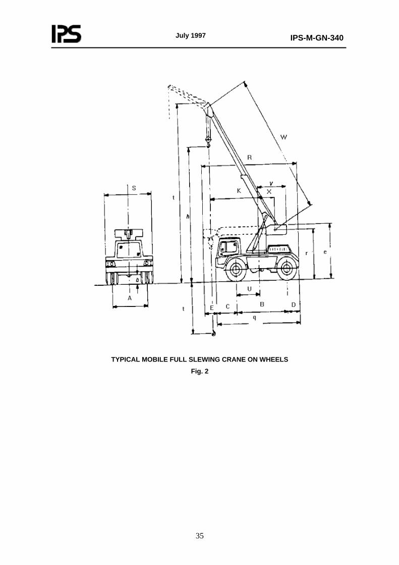
July 1997
IPS-M-GN-340
35
TYPICAL MOBILE FULL SLEWING CRANE ON WHEELS
Fig. 2
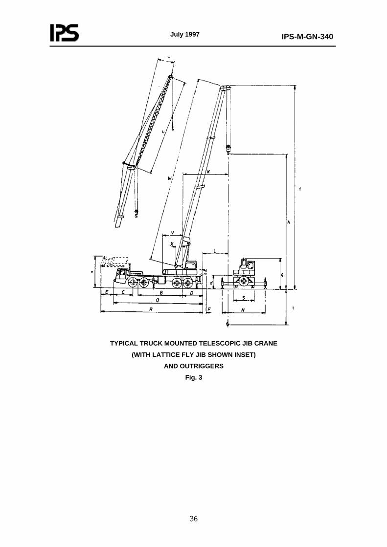
July 1997
IPS-M-GN-340
36
TYPICAL TRUCK MOUNTED TELESCOPIC JIB CRANE
(WITH LATTICE FLY JIB SHOWN INSET)
AND OUTRIGGERS
Fig. 3
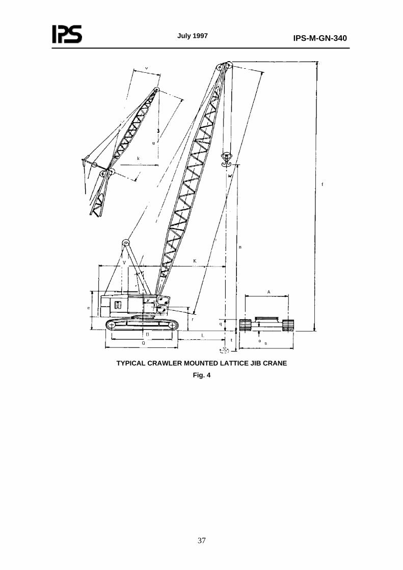
July 1997
IPS-M-GN-340
37
TYPICAL CRAWLER MOUNTED LATTICE JIB CRANE
Fig. 4
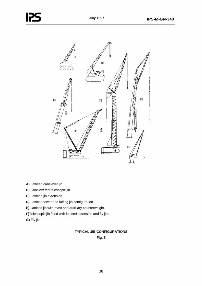
July 1997
IPS-M-GN-340
38
A) Latticed cantilever jib.
B) Cantilevered telescopic jib.
C) Latticed jib extension.
D) Latticed tower and luffing jib configuration.
E) Latticed jib with mast and auxiliary counterweight.
F)Telescopic jib fitted with latticed extension and fly jibs.
G) Fly jib.
TYPICAL JIB CONFIGURATIONS
Fig. 5
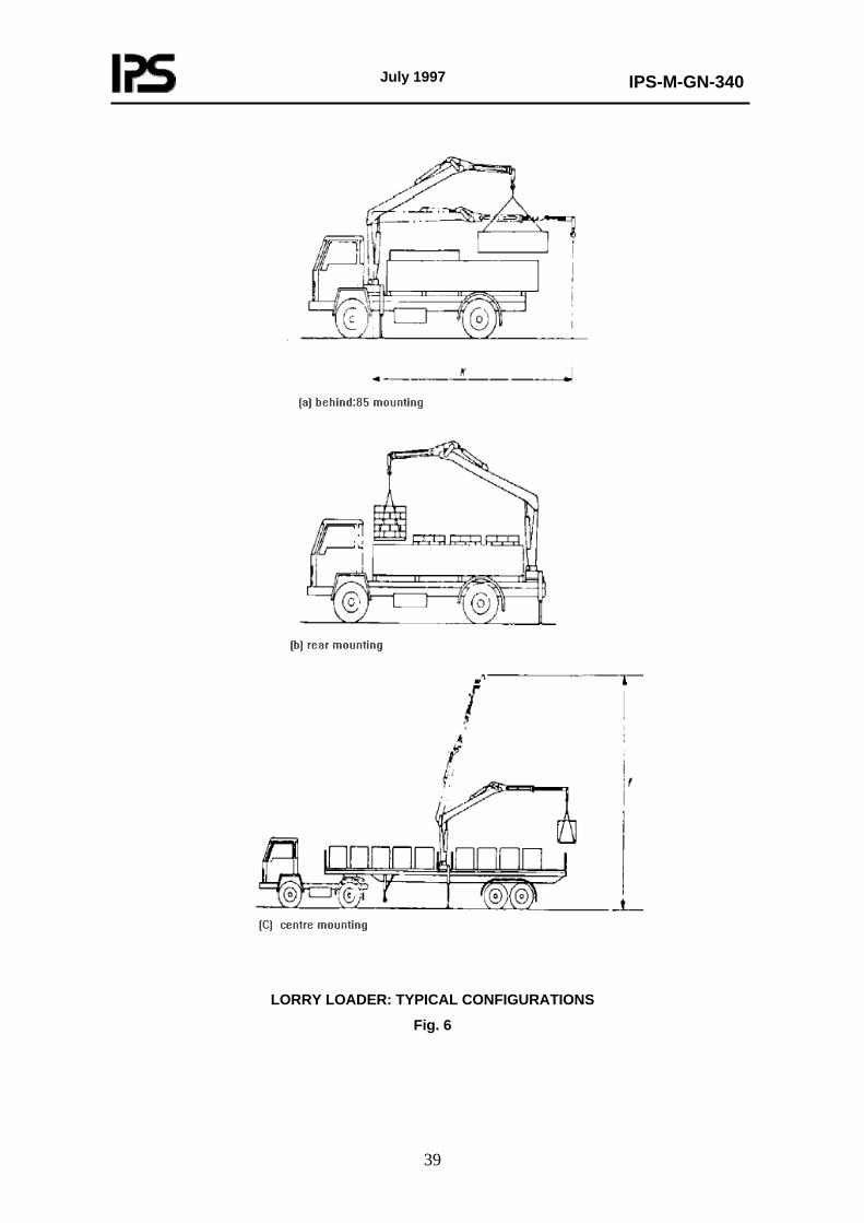
July 1997
IPS-M-GN-340
39
LORRY LOADER: TYPICAL CONFIGURATIONS
Fig. 6
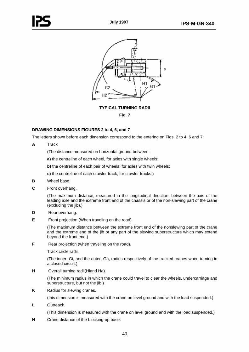
July 1997
IPS-M-GN-340
40
TYPICAL TURNING RADII
Fig. 7
DRAWING DIMENSIONS FIGURES 2 to 4, 6, and 7
The letters shown before each dimension correspond to the entering on Figs. 2 to 4, 6 and 7:
A Track
(The distance measured on horizontal ground between:
a) the centreline of each wheel, for axles with single wheels;
b) the centreline of each pair of wheels, for axles with twin wheels;
c) the centreline of each crawler track, for crawler tracks.)
B Wheel base.
C Front overhang.
(The maximum distance, measured in the longitudinal direction, between the axis of the leading axle and the extreme front end of the chassis or of the non-slewing part of the crane (excluding the jib).)
D Rear overhang.
E Front projection (When traveling on the road).
(The maximum distance between the extreme front end of the nonslewing part of the crane and the extreme end of the jib or any part of the slewing superstructure which may extend beyond the front end.)
F Rear projection (when traveling on the road).
Track circle radii.
(The inner, Gi, and the outer, Ga, radius respectively of the tracked cranes when turning in a closed circuit.)
H Overall turning radii(Hiand Ha).
(The minimum radius in which the crane could travel to clear the wheels, undercarriage and superstructure, but not the jib.)
K Radius for slewing cranes.
(this dimension is measured with the crane on level ground and with the load suspended.)
L Outreach.
(This dimension is measured with the crane on level ground and with the load suspended.)
N Crane distance of the blocking-up base.
July 1997
IPS-M-GN-340
41
Q Overall length (excluding the jib).
R Overall length (including the jib).
S Overall width (jib longitudinal).
T Overall width (superstructure slewed over side without jib).
U Distance from the center of rotation to the nearest axle or bogie.
V Tail radius.
W Center distance of jib.
X Distance of jib foot from center of rotation.
Z Width of crawler tracks
a Minimum ground clearance of the crane between the axles (the height above the ground of the lowest point between theaxles (excluding the axles and components fixed thereon).)
b Minimum ground clearance under the axles.
D Ground clearance of the slewing platform.
Q Overall height (jib in traveling position).
f Overall working height (for the relevant radius).
g Overall height (without the jib).
h Maximum height of hook (for the relevant radius).
q Height of crawler tracks.
r Height of jib foot from ground.
t Maximum depth of descent of the hook (for the relevant radius)
u Fly jib length.
v Fly jib offset.
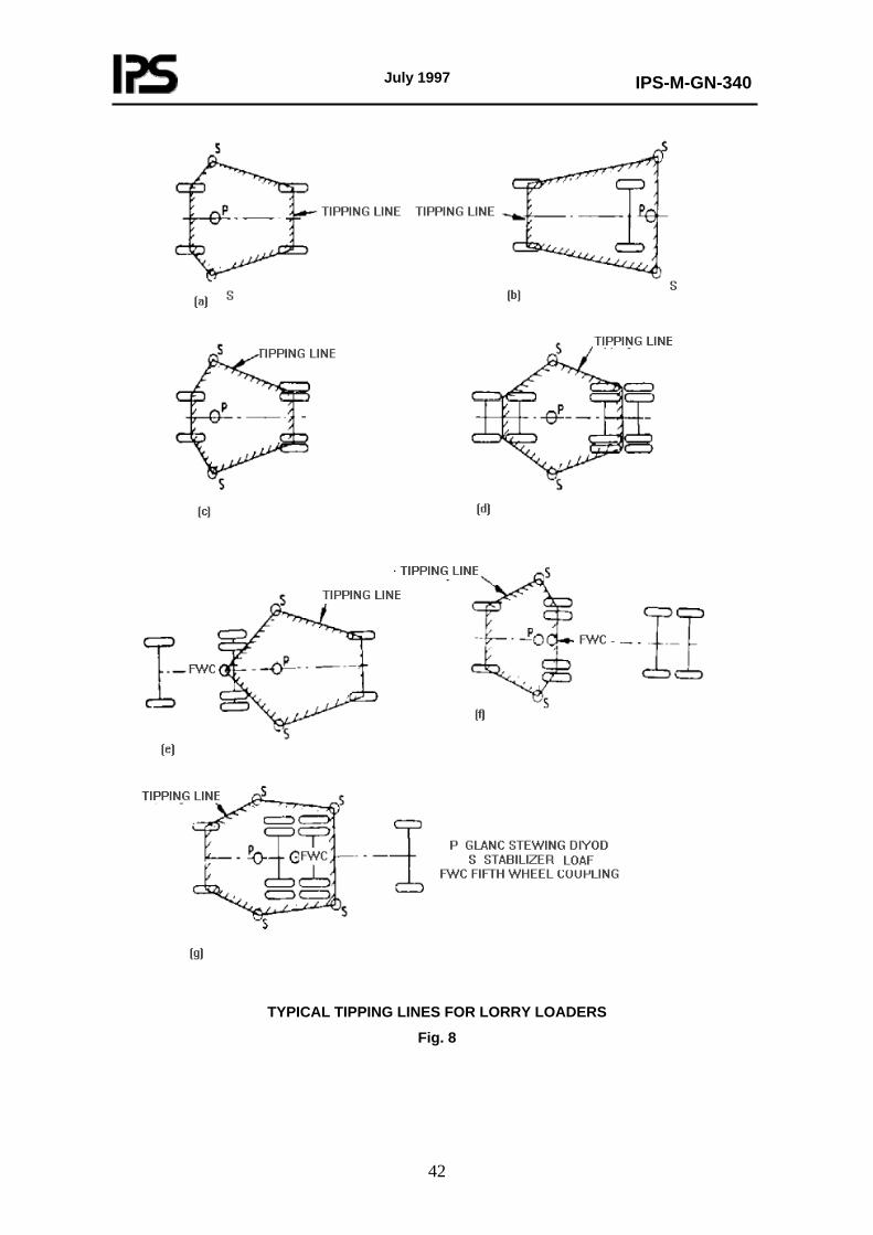
July 1997
IPS-M-GN-340
42
TYPICAL TIPPING LINES FOR LORRY LOADERS
Fig. 8
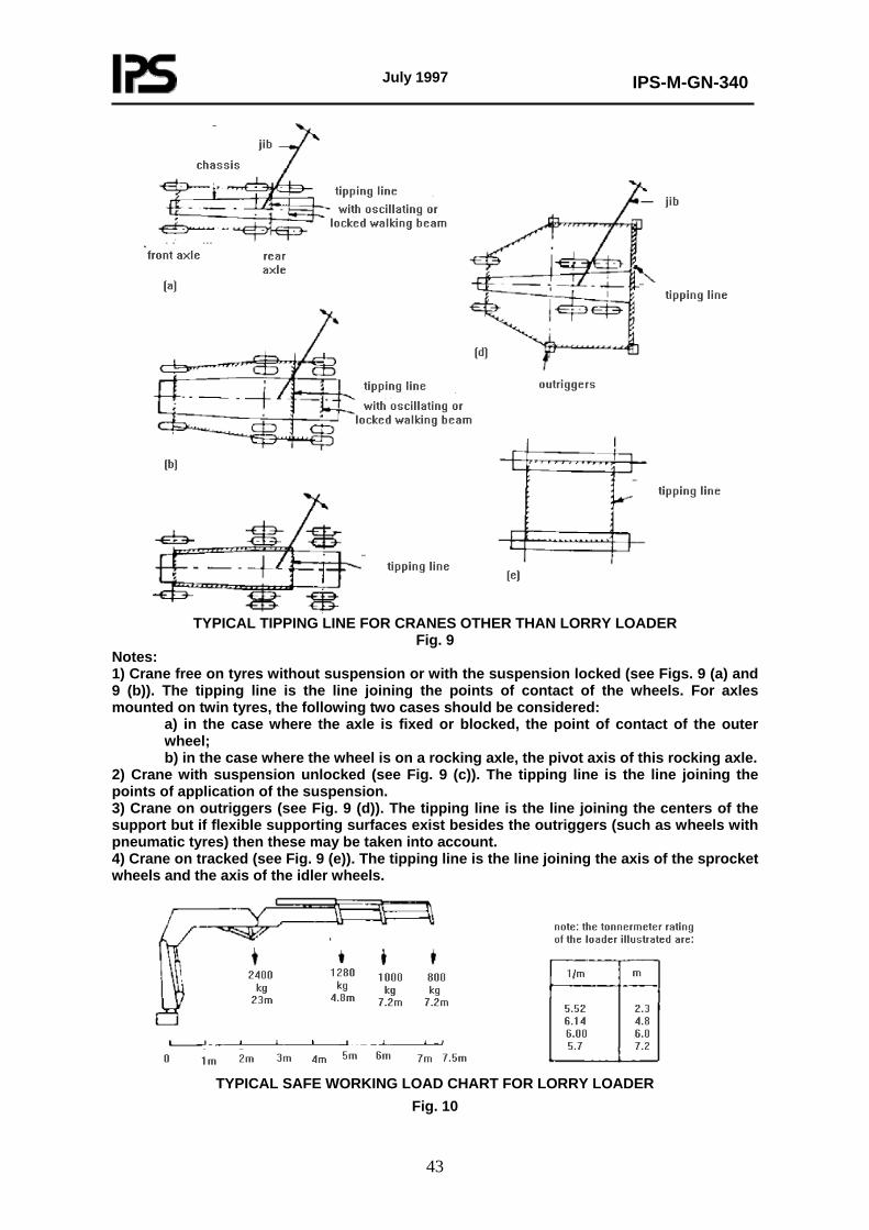
July 1997
IPS-M-GN-340
43
TYPICAL TIPPING LINE FOR CRANES OTHER THAN LORRY LOADER
Fig. 9 Notes: 1) Crane free on tyres without suspension or with the suspension locked (see Figs. 9 (a) and 9 (b)). The tipping line is the line joining the points of contact of the wheels. For axles mounted on twin tyres, the following two cases should be considered:
a) in the case where the axle is fixed or blocked, the point of contact of the outer wheel; b) in the case where the wheel is on a rocking axle, the pivot axis of this rocking axle.
2) Crane with suspension unlocked (see Fig. 9 (c)). The tipping line is the line joining the points of application of the suspension. 3) Crane on outriggers (see Fig. 9 (d)). The tipping line is the line joining the centers of the support but if flexible supporting surfaces exist besides the outriggers (such as wheels with pneumatic tyres) then these may be taken into account. 4) Crane on tracked (see Fig. 9 (e)). The tipping line is the line joining the axis of the sprocket wheels and the axis of the idler wheels.
TYPICAL SAFE WORKING LOAD CHART FOR LORRY LOADER
Fig. 10
July 1997
IPS-M-GN-340
44
APPENDICES
APPENDIX A INFORMATION RECOMMENDED SUPPLIED WITH ENQUIRY OR ORDER BY PURCHASER
A.1 Type of Crane and Duty Information should be provided that will enable the Manufacturer to select the most suitable crane from his ranged to meet the Purchaser’s requirements or, alternatively, to suggest a modified standard product. The information should include information regarding characteristics that are required, (see clause 1). A.2 Crane duty The following information should be provided regarding the crane duty:
a) Size and type of loads, maximum height of lift and radius. Where loadings at intermediate radii are likely to be significant, details should also be given. For cranes with adjustable or telescopic jibs, these details should be given for all required jib lengths and radii. b) Nature of material to be handled and its mass density. c) Details of loads to be handled. d) Full details of any duty that is required.
A.3 Type of Suspension and Chassis State whether wheeled or crawler suspension is required and whether a road vehicle carrier is required. A.4 Site Conditions The following information on site conditions should be provided:
a) Nature of ground over which the crane will have to operate, e.g. hard roads, temporary roads, hardstanding, grassland, or cross country; and whether the machine will have to travel on the public highway. Details of any physical or statutory limitations should be given. b) Any environmental limitations, e.g. proximity of potentially flammable or corrosive atmosphere. c) Climatic conditions including details of annual ambient temperature and humidity. d) Approximate altitude above sea level. e) Headroom available for working conditions. f) Height of any doorway or overhead beam under which the crane, with or without load, has to pass. g) Width of any doorway, road or passage-way, together with width of any branch road into which the crane has to turn and maximum clearance width for a full circle turn(if applicable). h) Where applicable details of any overhead lines, etc. that may restrict operation or movement. i) Particulars of any gradient, i.e. maximum slope and length the crane will be required to travel, the frequency of negotiation and whether loaded or unloaded.
(to be continued)
July 1997
IPS-M-GN-340
45
APPENDIX A (continued)
j) Any special limitations of axle load or ground pressure under wheels or crawler.
k) Any limitations on extension dimensions or ground pressure for outriggers.
l) If possible a sketch should be given showing site conditions and clearances.
A.5 Lifting Characteristics
The following information on the lifting characteristics of the crane should be provided:
a) Whether auxiliary hoist is required in addition to main hoist, indicating required load rating.
b) Any requirement or limitation regarding lifting speed.
c) Range of lift of hook(s).
d) Any usual or exceptional duty.
e) Details of alternative, extra, or unusual equipment or attachments, e.g. length and number of jib inserts, details of fly jib, etc.
f) Details of any specific safety load limiting devices, etc. required (see A.9)
A.6 Cab
The following information on the cab should be provided:
a) Any special visual requirements, e.g. window to permit low vision below cab.
b) Any special environmental conditions influencing cab design, e.g. air conditioning, special insulation in extreme climates, etc.
c) Any special requirements for cab access.
A.7 Motive Power Unit
State type of prime mover required, or, where appropriate, details of external electricity supply.
A.8 Power Transmission and Control System
The following information on power transmission and control systems should be provided.
a) Preference for mechanical, hydraulic, hydrodynamic, hydrostatic, air, electric operation of main transmission and control auxiliary system.
b) Any special operator controls or instrumentation.
A.9 Traveling with Load
State whether crane has to be capable of traveling with load.
(to be continued)
July 1997
IPS-M-GN-340
46
APPENDIX A (continued)
A.10 Safety Devices and Alarms
The following information on safety devices and alarms should be provided:
a) Details of any safe load indicator, audible or visual alarm or cut-out specified by regulation or statute.
b) Any other safety control equipment or device to be fitted.
A.11 Additional Information
The following information should also be provided:
a) Particulars of any further requirements of special conditions not included above, e.g. lighting, power load lowering, braking, etc.
b) Any aspect of maintenance or servicing procedure that may require particular attention, e.g. any local limitations on serving facilities or manpower.
c) Any shipping limitations e.g. weight, dimensions, method of slinging and available transport facilities.
July 1997
IPS-M-GN-340
47
APPENDIX B
INFORMATION TO BE SUPPLIED BY MANUFACTURER
B.1 General
The information to be supplied in the tender by the Manufacturer should include appropriate data from B.2 to B.6 together with such additional information necessary to satisfy the enquiry, this IPS standard, and, where relevant, the recommendations of Appendix A.
B.2 Types of Crane and Duty
The following information shall be provided.
a) Type.
b) Drawing and/or catalogue reference.
c) For jib cranes, total length, number and assembly of sections.
d) For telescopic cranes, jib length and number of extensions.
e) Safe working loads at maximum and minimum radii, and such other significant radii as may be specified in enquiry, relevant to A.2(a). This information should be given for all jib lengths and configurations included in the tender, the main hoist, and, where fitted, auxiliary hoist.
f) Details of rope reeving for main hoist( and where appropriate auxiliary hoist) for all relevant jib configurations and loads.
g) Range of lift of hook(s) for all configurations above ground level.
B.3 Machine Characteristics
A schedule together with a drawing or diagram shall be supplied giving physical dimensions, etc. of the crane, of which the following items are typical:
a) Overall length, width and height of crane both in shipping condition and assembled ready for operation.
b) Shipping and operational weights, stating weight of heaviest piece to be handled during site assembly, and size and weight of any separate counterweight.
c) Details and dimensions of crawlers for tracked machines.
d) Number and disposition of axles for wheeled machines, including tyre details.
e) Turning circle, with particular reference to the minimum distance between two parallel walls within which the crane chassis can be completely turned round in a single movement, both for ’right lock’ and ’left lock’.
f) The maximum gradient on which the crane may travel unloaded, and, where appropriate, loaded.
g) Dimensions, including axle loads, and speeds for various gear ratios, in highway traveling condition (where applicable).
h) Overall dimensions with outriggers extended.
i) Dimensional position of extreme outer edge of tracks or out rigger jack pads relative to the centreline of the revolving superstructure. (to be continued)
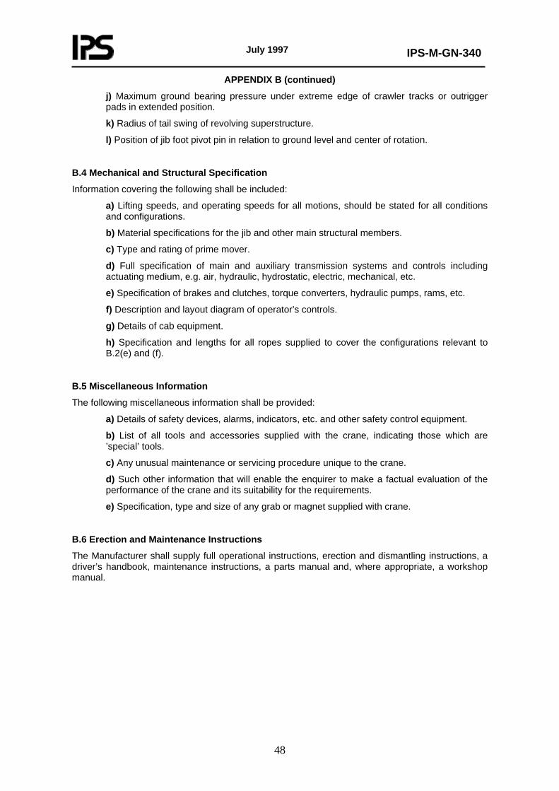
July 1997
IPS-M-GN-340
48
APPENDIX B (continued)
j) Maximum ground bearing pressure under extreme edge of crawler tracks or outrigger pads in extended position.
k) Radius of tail swing of revolving superstructure.
l) Position of jib foot pivot pin in relation to ground level and center of rotation.
B.4 Mechanical and Structural Specification
Information covering the following shall be included:
a) Lifting speeds, and operating speeds for all motions, should be stated for all conditions and configurations.
b) Material specifications for the jib and other main structural members.
c) Type and rating of prime mover.
d) Full specification of main and auxiliary transmission systems and controls including actuating medium, e.g. air, hydraulic, hydrostatic, electric, mechanical, etc.
e) Specification of brakes and clutches, torque converters, hydraulic pumps, rams, etc.
f) Description and layout diagram of operator’s controls.
g) Details of cab equipment.
h) Specification and lengths for all ropes supplied to cover the configurations relevant to B.2(e) and (f).
B.5 Miscellaneous Information
The following miscellaneous information shall be provided:
a) Details of safety devices, alarms, indicators, etc. and other safety control equipment.
b) List of all tools and accessories supplied with the crane, indicating those which are ’special’ tools.
c) Any unusual maintenance or servicing procedure unique to the crane.
d) Such other information that will enable the enquirer to make a factual evaluation of the performance of the crane and its suitability for the requirements.
e) Specification, type and size of any grab or magnet supplied with crane.
B.6 Erection and Maintenance Instructions
The Manufacturer shall supply full operational instructions, erection and dismantling instructions, a driver’s handbook, maintenance instructions, a parts manual and, where appropriate, a workshop manual.

July 1997
IPS-M-GN-340
49
APPENDIX C
MOBILE CRANE DATA SHEETS
SHEET 1 OF 4 1 PROJECT No.: ORDER No. : 2 SERVICE: ITEM No. : 3 No. REQD TYPE 4 5 ENVIRONMENTAL DATA OPERATING DATA 6 OPERATING TEMP. LIFTING CAPACITY 7 Max. AMBIENT TEMP. REDIUS (m) 8 Max. WIND SPEED: OPERATING STOWED LIFTING HEIGHT: 9 WIND PRESSURE: OPERATING SPEEDS: 10 LIFTING 11 AREA CLASSIFICATION: SLEWING 12 13 SLEWING ANGLE 14 LIFTING ANGLE 15 CONSTRUCTION DATA 16 DESIGN CODE: 17 PRIME MOVER TYPE: DRIVER POWER: 18 BOOM TYPE: BOOM LENGTH: 19 LIFTING RADIUS: min.: 20 max.: 21 HOOK TYPE: MATERIAL: SAFETY LATCH 22 23 NOTES: 24 25 26 27 28 29 30 31 32 33 34 35 36 37 38 39 40 41 42
(to be continued)

July 1997
IPS-M-GN-340
50
APPENDIX C (continued)
SHEET 2 OF 4 1 PROJECT No.: ORDER No. : 2 DRUM BOOM HOIST MAIN HOIST AUXILIARYHOIST 3 TYPE 4 DIAMETER 5 LENGTH 6 MATERIAL 7 PITCH / ROPE Dia. RATIO 8 ROPE WRAPS 9 GUIDING DEVICE 10 ROPE SPOOLING DEVICE 11 GROOVE RADIUS 12 HEIGHT 13 PITCH 14 DRUM THICKNESS 15 ROPE 16 ROPE MANUFACTURER 17 NOMINAL DIAMETER 18 TYPE / No. OF STRANDS 19 CORE TYPE 20 BREAKING LOAD 21 SAFETY FACTOR 22 23 HYDRAULIC UNIT: 24 TANK CAPACITY 25 PUMPS TYPE 26 MOTOR POWER 27 OPERATING / DESIGN PRESSURE 28 ACCUMULATOR No. / VOLUME / PRESSURE 29 HAND PUMP 30 31 DRIVER'S CABIN 32 33 ACCESORIES 34 ANTICOLUSION DEVICE 35 TYPE 36 LOCATION 37 FIRE EXTINGUISHERS 38 39 OVERLOAD WARNING DEVICE 40 41 NOTES: 42
(to be continued)

July 1997
IPS-M-GN-340
51
APPENDIX C (continued)
INDUSTRIAL COMBUSTION ENGINE
SHEET 3 OF 4 NO. PROJECT No.: ORDER No. :
1 SHAVES: 2 DIAMETER 3 MATERIAL 4 MATERIAL 5 LUBRICATION 6 SHEAVE GUARD 7 BRAKES: 8 TYPE 9 HOLDING TORQUE
10 BOOM HOIST: 11 TYPE 12 HOISTING CAPACITY 13 14 15 16 GEARS DESIGN CODE 17 BOOM HOLDING DEVICE TYPE 18 19 SWING MECHANISM: 20 BRAKE TYPE 21 SWING LOCK 22 BEARING TYPE 23 24 MAIN HOIST: 25 GEARING TYPE / MATERIAL 26 TRANSMISSION RATIO 27 DESIGN COD / SERVICE FACTOR 28 LUBRICATION SYSTEM 29 30 AUXILIARY HOIST: 31 GEARING TYPE / MATERIAL 32 TRANSMISSION RATIO 33 DESIGN CODE, SERVICE FACTOR 34 LUBRICATION SYSTEM 35 36 37 38 39 40 41 42
(to be continued)

July 1997
IPS-M-GN-340
52
APPENDIX C (continued) No. PROJECT No.: ORDER No. : 1 SERVICE: No. REQUIRED: ITEM 2 MANUFACTURER: TYPE 3 RATED kW AT SITE CONDITIONS: rpm SERIAL No.: 4 5 OPERATING DATA CONSTRUCTION
DAtA 6 STROKE: CYCLE: CYLINDER No.: ARRANGEMENT: 7 rpm: DESIGN / max. / min. PISTON: STROKE mm BORE mm 8 max. CONTINUOUS kW (STD. COND'S): No. OF RINGS: 9 RATED kW (NET AT SITE COND.): RATED rpm: TOTAL DISPLACEMENT: cm³ 10 BMEP AT WORKING CONDITIONS: kg/cm² VALVES: TYPE: No. 11 FUEL TYPE: MAIN BEARING: TYPE No. 12 FUEL CONSUMPTION: kg/W/h AT FUEL LOAD
LENGTH: DIAMETER:
13 kg/kW/h AT ½ LOAD INJECTION SYSTEM: 14 kg/W/h AT ½ LOAD SUPERCHARGING SYSTEM: 15 KOTATION (PROM COUPL. END.) 16 DRIVEN MACHINE ITEM:
KOTATION (PROM COUPL. END.)
17 TYPE SPEED GOVRNOR: 18 BHP: DESIGN: kW max.: kW TRANSMISSION: 19 Rpm 20 ROTATION (PACKING COUPLING END): ACCESSORIES 21 AIRINLETFILTER:MAKETYPE No. 22 SITE DATA AND UTILITIES FUELFILTER:MAKE TYPE No. 23 INSTALLATION EXHAUST SILENCEKPLEX PIPE: 24 ALTITUTE: m BAROMETER kg/cm² BATTERY TYPE CAPACITY A/ti 25 TEMPERATURE: SUMMER: WINTER: BATTERY CHARGER 26 RET. HUMIDITY BASEPLATE: 27 DESIGN CONDITION: FUEL TRANSFER PUMP: 28 MAINTENANCE TOOLS: 29 EL POWER CONTROL PANEL: 30 FUEL TANK: IT 31 COOLING SYSTEM: TYPE INSTRUMENTS 32 CIRC. WATER PUMP PRESS GAGES: OIL:WATER: 33 WATER COOLER TEM. GAGES: OIL:WATER: 34 ACCESSORIES: FUEL LEVEL INDICATOR: 35 TACHOMETER: 36 LUBRICATION SYSTEM: TYPE: ALARMS AND SHUTDOWNS: 37 MAIN PUMPS: DRIVEN BY: LOW OIL PRESS: HIGH OIL TEMP.: 38 AUX. PUMP: DRIVEN BY: HIGH WATER TEMP.OVER SPEED: 39 FILTER: LOW FUEL LEVEL: LOW TENSION BATT.: 40 OIL COOLER: 41 OIL TYPE: SHOP TEST: 42 OIL CONSUMPTION: REQUIRED OBSERVED WITNESS
43 MFRSTD.SHOPTES
44 PERFORM-ANCETEST
45 No. CONSECUTIVE STARTS: NOLOADTEST 46 47 MATERIALS: WEIGHTS:MOTOR: kgACC: kg TOTAL: kg 48 FRAME VALVES: PISTON RINGS: 49 CYLINDERS: CYLINDER HEAD: VALVESEALS: 50 PISTONS: CYLINDER LINERS: 51 NOTES:


![FnIO G-Series: GN-9481 / GN-9482 / GN-9483Spec] GN-9481_GN...Run-Time System Multiple PLC Tasks Program Languages IEC 61131-3 (LD, IL, ST, FBD, SFC) OPC-Server GN-9481 Not supporting](https://img.pdfslide.us/doc/110x75/5fcf359602c376594f0af992/fnio-g-series-gn-9481-gn-9482-gn-9483-spec-gn-9481gn-run-time-system-multiple.jpg)