Embed Size (px)
Citation preview

2001 - 2004
Performance Assessment and Benchmarking in Application:
Turbine Control System
• Background– Plant description – The control objectives
• Turbine Controller benchmarking• Discussions
General Introduction

Coal Fired Power Plant
1 steam generator2 denox3 economiser4 compressor5 electrostatic
precipitator6 desulfurisation7 smoke stack
8 steam turbine9 condenser10 pump11 economiser12 feed water tank13 generator14 transformer
gypsum flue dust aircoal
ash
fresh water
condensate
coolingwater
cooling tower
coolingair
electricalenergy
flue gas
ammoniac
limeemulsion
cleanedflue gas
14
1010
9
8
13
11
10
12
11
1
3
2
4
5
6
4
7
boiler house engine house distributing networkflue gas system
live steam
feedwater-

Coal Fired Power Plant : Steam Generation
In a coal fired power plant, a boiler is used to generate steam for a dedicated turbo-alternator set. Coal is transported from ground stock, dried and milled to form a pulverised fuel which is transported through pipes to the burners by a heated air stream. It is then blown into the boiler furnace and combusted. The heat released is absorbed in the water cooled furnace walls in which the majority of the steam is generated.
The steam generated in the furnace is then superheated in further stages of heat exchanger tubing before being fed to the turbine. After expansion in the HP turbine stage, the steam is returned to the boiler for reheating before the final expansion in the IP and LP turbine stages. After condensation in a water or air cooled condenser, the condensate is pumped back to the boiler via a series of regenerative feed heaters which are fed by steam tappings from the main turbine.
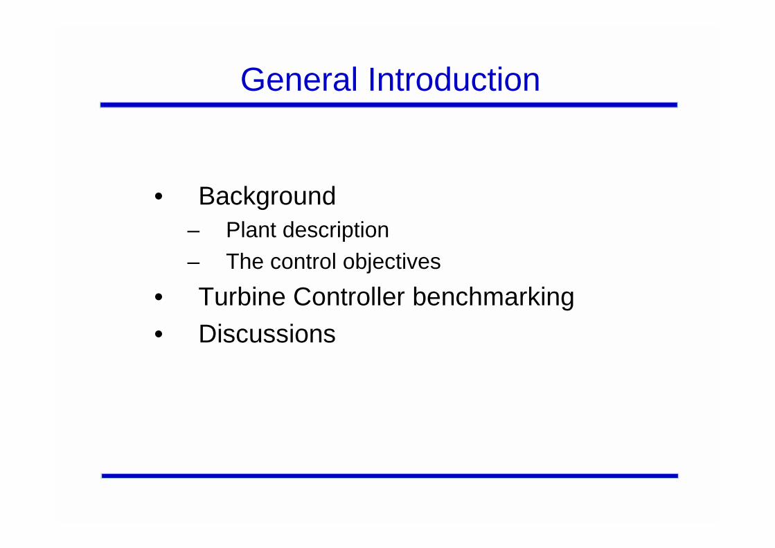
Coal Fired Power Plant: Turbine System
P o si ti o nC o ntr o ll e r
Sp e e d a n dL o a d
C o n tro ll e r
M S C V
R e h e ate r
IPH P
n Actual
+
Po s iti o n
n Referen ce
G en e ra to r
L PB o il er
C o n d en se r
R C V
+
-
-
C o ntr o ll e r
I PB C V
H PBC V
E le ct ri ca lG ridPr es su re
Con tr oller-
+HPBS
Pr ess ur eC on tro ller
-
+ IPBS
2 50 b a r5 40 ° C
5 0 b ar3 19 ° C
50 b a r54 0 °C
7 b a r2 6 0 °C
0. 05 b ar32 .1 ° C
P Actual
P Referen ce
p Actual
p Refer ence
p Reference
p Actual
Overall Turbine Control Objectives
For the coal fired power plant, the control objectives are load and speed control of a steam turbine.
The speed and load control are integrated into one control system. Of prime interest for speed control is the performance during turbine start-up. This covers run-up speed to warm-up or nominal speed as quickly as possible and afterwards maintaining at constant speed as well as synchronising a turbineto the electrical grid.
Load control is active after synchronising a turbine to the electrical grid. This covers run-up load to nominal load as quickly as possible and afterwards maintaining at constant load. A load rejection takes place when a turbine is suddenly cut-off from the electrical grid.

Turbine Control Objective : Load Rejection
The prime objective is to reduce turbine load as quickly as possible and simultaneously limit over speed.
Load rejections down to 15% of nominal load contain speed and load control, while load rejections down to less than 15% contain only speed control.
The steam turbine power plant contains a high pressure (HP) and intermediate pressure (IP) bypass control system to maintain safety operation limits. The HP bypass system controls the main steam pressure while the IP bypass system controls the reheat pressure as long as the steam generator is producing more steam than the steam turbine can accept.

Definitions of Process Variables
Outputs InputsY1: Load U1: Speed/Load controller Y2: Speed U2: HP bypass control valveY3: Reheater Pressure U3: IP bypass control valve
Currently applied pairing between MVs and PVs:Load – Main steam and reheat control valve Y1(U1)Speed – Main steam and reheat control valve Y2(U1)Reheater pressure – HP and IP bypass control valveY3(U3,U4)
Feedforward variables and disturbances are caused by: Load demand from grid

Detailed Control Objectives
SpeedRun-up steam turbo set from 0 to nominal speedControl at constant operation speedSynchronise steam turbo set with electrical gridTake part in frequency stabilisation by parallel operationSecure overspeed at load rejection

Detailed Control Objectives
Bypass System
Separates boiler from turbine
Bypass control systems work as start-up valves
Bypass control systems work as pressure limiting
valves
High pressure safety valves are avoided

Detailed Control Objectives
LoadFast loadingControl at constant load operationControl at transient load operationInteraction with speed controller to avoid overspeedKeep the power plant in stand-by mode for fast return to electrical grid

Control Performance Assessment : SISO
Since there are no stochastic disturbance or reference signals in the turbine unit, it will be inappropriate to use the MV and GMV benchmarking indices.
Even though the RS-LQG benchmark algorithm is primarily designed for assessing the performance of process with stochastic disturbance and reference signals, in principle, this benchmark algorithm can still be utilised if the system does not have either a stochastic disturbance, stochastic reference or both.
Therefore, the turbine control system has only been benchmarked with the RS-LQG algorithm.
RS-LQG Benchmarking Test Set-up
For RS-LQG performance assessment, the existing controllers were benchmarked against the optimal RS controller in the three cases of load rejection, speed run up and load run up conditions. For the load rejection tests, the performances of the speed and load controller were assessed in three different cases of load rejections: from 100% down to 10%, 50% and 80% of nominal load; this corresponds to typical abnormal operating conditions.
For the speed run up tests, the performance of the speed controller was assessed for three different speed trajectories defined by the reference and time vectors. Since, in these transients, the unit is not yet connected to the electrical grid, the load controllerperformance was not assessed.

RS-LQG Benchmarking Test Set-up
For the load run up tests, the performance of the load controller was assessed for the trajectory defined by the load reference and time vectors. This trajectory is the typical unit reference for the load run-up transient. The performance of the speed controller was not assessed as, in this case, the unit is connected to the electrical grid: this means that the turbine speed is fixed by the grid frequency and is independent from the speed controller.

Analysis of RS-LQG Benchmarking
To compute the performance index, the RS-LQGbenchmark algorithm needs the polynomial transfer function describing the process, the disturbances and the reference. For this case study, SISO system identification was performed. The different simulations were run and the plant data were collected: set points, controller output and plant output.
For the speed loop, four different system identifications were performed corresponding to the three load rejections and the nominal speed run up cases. For the load loop, four different system identifications were performed corresponding to the threeload rejections and the nominal load run up cases. Thus in totaleight plant models were obtained, four for the speed loop and four for the load loop.

Analysis of RS-LQG Benchmarking
As characteristics of non-linear processes, the four transfer function models identified for the speed loops, as well as those for the load loop, all have different dynamics. Since the RS-LQG benchmarking algorithm is model specific, then 8 different optimal RS controllers will be obtained, four for each loop.
However, the actual controller is the same for all operating conditions, normal and abnormal (i.e. it is not foreseen to have controller parameters and structure as a function of operating conditions);expecting the performance of the existing controller to match those of different optimal RS controllers is unrealistic. Nevertheless, if the performance of the existing controller is comparable with those of the optimal RS controllers, then the existing controller is quite good.

RS-LQG Weighting Selection
The RS-LQG algorithm requires a set of dynamic error and control weightings to compute the performance index. Since we are interested in the dynamic performance of the process in this case study, these weightings are chosen to reflect this desire to assess dynamic performance.
As the system has no stochastic excitation, the error weighting was chosen to contain an integral action in order to ensure zero steady state error, while the control weighting was chosen to be a scalar term penalising control action.
In the following slides, we are going to show the transient responses of the RS-LQG controller and the original controller.

Load Rejection 100% to 10%
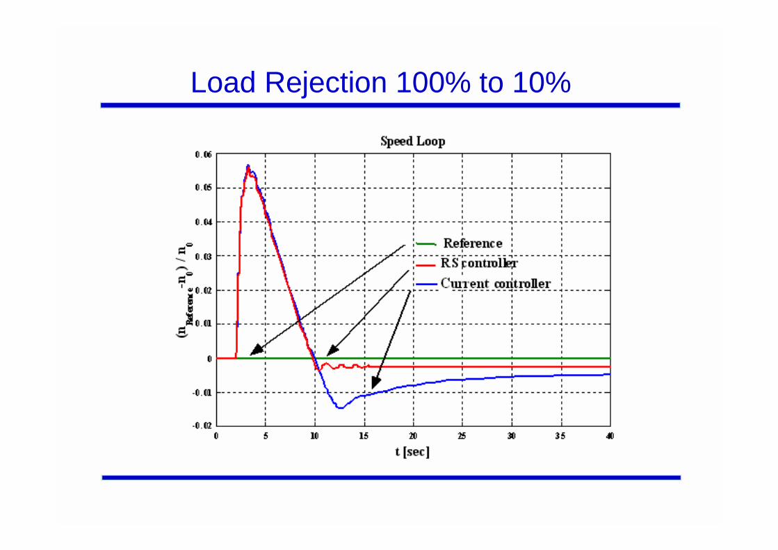
Load Rejection 100% to 10%
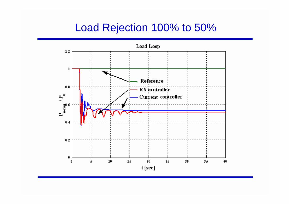
Load Rejection 100% to 50%

Load Rejection 100% to 50%

Load Rejection 100% to 80%

Load Rejection 100% to 80%

Speed Trajectory I

Speed Trajectory II

Speed Trajectory III

Load Run Up
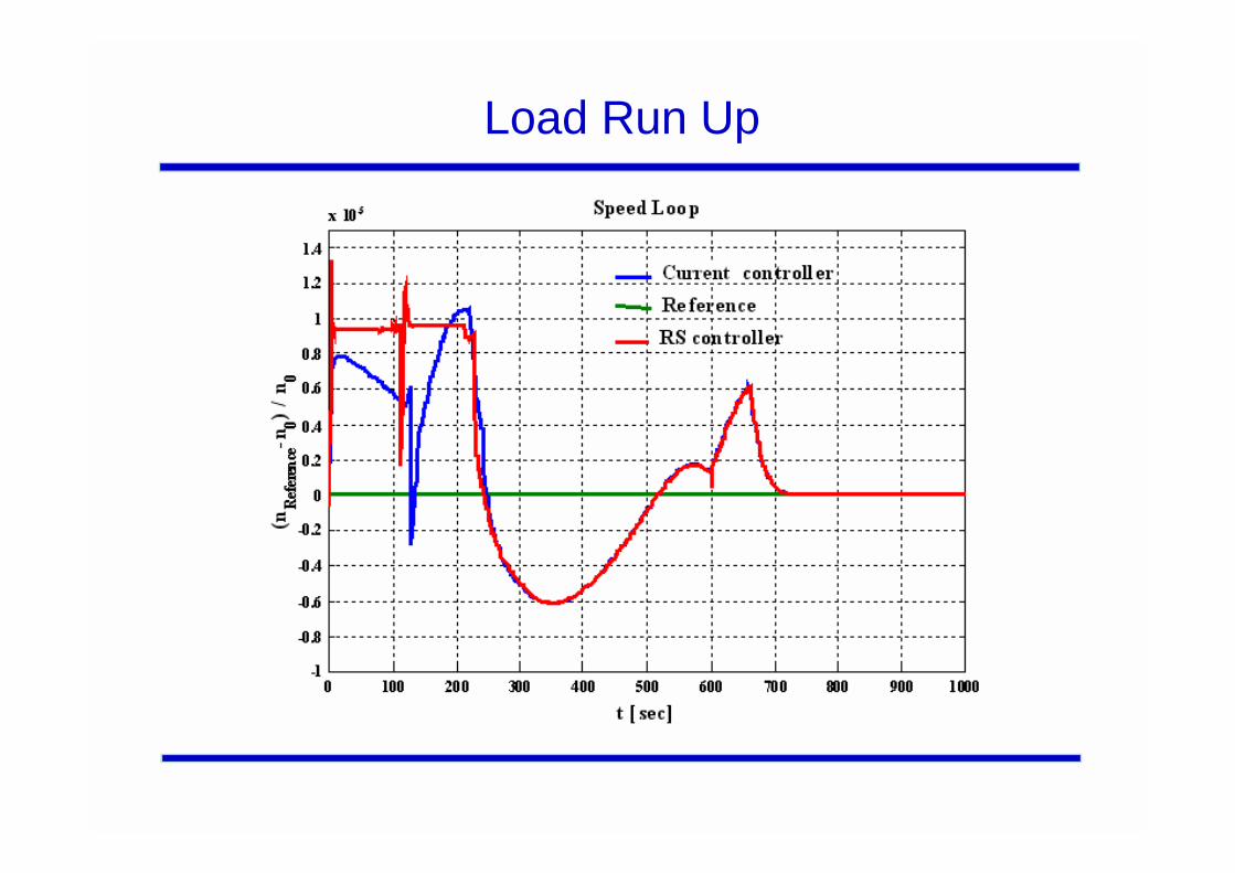
Load Run Up

Interpretation of the Benchmarking Result
As expected, the linearised RS-LQG controller gives better performance. However, it must be noted that the RS controllers are much more aggressive in terms of control actions: for all transients, the main control valve and the reheat control valve are highly disturbed and have to work hard to achieve low benchmark cost.
Furthermore, it is necessary to keep in mind first that for thermal and mechanical reasons which are not simulated, the speed run-up transient can not be as fast as wanted; the slower transient proposed in these tests already has the maximum acceptable speed rate.

Interpretation of the Benchmarking Result
For load loop control, during loading transient, the RS controllers perform slightly better than the original controllers as the set point tracking is better for low load level. Nevertheless, this loading transient may be too fast for real plant as, in the two simulations, the load set point can no longer be tracked when the loading ramp gets over the 40% load level; this is not related to control problems but is only due to boiler dynamics slower than the loading ramp.
For load rejection transients, as for speed control, it can be observed that the RS controller has a smaller steady state error than the SIEMENS controller. The 90% load rejection does not show significant differences of load control between the two controllers; as the final value of load set point was set to 0, the differences are attributable to the speed controller.

Assessment of the Original Controller
From the previous discussions, we have come to the conclusion that the original PID controller is performing very well. There is very little room left for improvement.
The designers of the original controller should be congratulated for their achievements.

Conclusions
• SISO RS-LQG benchmarks provide a wealth of useful information.
• Engineering judgement is still an essential part of the benchmarking process.
• The control/optimisation problem should be defined, then the benchmark tool that fits bestshould be chosen.